


Copyright © 2008 by Elenco® Electronics, Inc. All rights reserved. No part of this book shall be reproduced by |
753305 |
any means; electronic, photocopying, or otherwise without written permission from the publisher. |
|
|
|

Table of Contents
Basic Troubleshooting |
1 |
Advanced |
|
Parts List |
2 |
Troubleshooting |
9 |
|
|
||
How to Use It |
3 |
Project Listings |
10 |
|
|
||
About Your Snap |
|
Projects #1-63 |
11-43 |
|
|
|
|
Circuits® Parts |
4, 5 |
Other Snap Circuits® |
|
How It Works |
6, 7 |
Products |
44 |
|
|
||
General Operating |
|
Bonus Projects B1 & B2 45 |
|
|
|
|
|
Instructions |
7 |
Parts Map |
46 |
DO’s and DON’Ts of |
|
|
|
Building Circuits |
8 |
|
|
|
|
|
|
WARNING FOR DISC LAUNCHER (DL) - Moving parts. Keep your face and eyes away from the front of the disc launcher and from flying discs. Do not place anything into the disc
!launcher except the foam discs. Do not reach inside the disc launcher during operation. Do not launch discs at people, animals, or objects. Eye protection is recommended.
A NOTE ABOUT THE FCC
The Federal Communications Commission (FCC) regulates use of the radio frequency spectrum in the United States to prevent products from interfering with each other.
Deluxe Snap Rover® has been tested and found to comply with the limits for a Class B digital device, pursuant to part 15 of the FCC Rules. These limits are designed to provide reasonable protection against harmful interference in a residential installation. Deluxe Snap Rover® generates, uses and can radiate radio frequency energy and, if not installed and used in accordance with the instructions, may cause harmful interference to radio communications.
However, there is no guarantee that interference will not occur in a particular installation. If Deluxe Snap Rover® does cause harmful interference to radio or television reception, which can be determined by turning Deluxe Snap Rover® off and on, try to correct the interference by:
1.Moving Deluxe Snap Rover® away from the receiver.
2.Contacting Elenco® Electronics for help by calling (800) 533-2441, or e-mail us at help@elenco.com.
FCC regulations for your Deluxe Snap Rover® require you to accept any interference from authorized sources and that you shut down if you are causing interference with other authorized products.
You should never modify the electrical circuit components inside your Deluxe Receiver (RX2) or Remote Control transmitter as this may cause malfunctions or violate FCC regulations for this product.
Warning to Snap Circuits® Owners: Do not use parts from other Snap Circuits® sets
!with this kit. Deluxe Snap Rover® uses higher voltage which could damage those parts. Page 44 and our website www.snapcircuits.net has approved circuits that you can use.
WARNING: SHOCK HAZARD - Never connect Snap Circuits® to the electrical outlets in your home in any way!
Basic Troubleshooting
1.Most circuit problems are due to incorrect assembly, always double-check that your circuit exactly matches the drawing for it.
2.Be sure that parts with positive/negative markings are positioned as per the drawing.
3.Be sure that all connections are securely snapped.
4.Try replacing the batteries in the Rover body and remote control unit.
5.Keep the wheels clean and free of lint, thread, or dirt.
6.If the disc launcher jams, turn the circuit off and remove all discs.
Elenco® Electronics is not responsible for parts damaged due to incorrect wiring.
Note: If you suspect you have damaged parts, you can follow the Advanced Troubleshooting procedure on page 9 to determine which ones need replacing.
WARNING: Always check your wiring before turning on a circuit. Never leave a circuit unattended while the batteries are installed. Never connect additional batteries or any other power sources to your circuits.
WARNING: CHOKING HAZARD - Small |
Conforms to |
parts. Not for children under 3 years. |
ASTM F963-96A |
|
|
BATTERIES:
•Use only 1.5V AA type in the Rover body and 9V in the remote control (not included).
•Insert batteries with correct polarity.
•Non-rechargeable batteries should not be recharged. Rechargable batteries should only be charged under adult supervision, and should not be recharged while in the product.
•Do not mix alkaline, standard (carbon-zinc), or rechargeable (nickel-cadmium) batteries.
•Do not mix old and new batteries.
•Remove batteries when they are used up.
•Do not short circuit the battery terminals.
•Never throw batteries in a fire or attempt to open its outer casing.
•Batteries are harmful if swallowed, so keep away from small children.
-1-
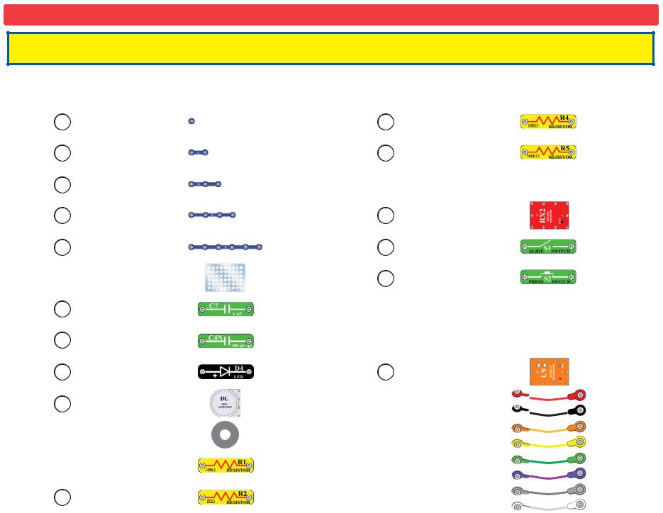
Parts List (Colors and styles may vary) Symbols and Numbers
Important: If any parts are missing or damaged, DO NOT RETURN TO RETAILER. Call toll-free (800) 533-2441 or e-mail us at: help@elenco.com. Customer Service • 150 Carpenter Ave. • Wheeling, IL 60090 U.S.A.
Qty. |
|
ID |
Name |
Symbol |
Part # |
|
Qty. |
ID |
Name |
Symbol |
Part # |
||
|
|
|
|
|
|
|
|
|
|
|
|
|
|
5 |
1 |
|
1-Snap Wire |
|
6SC01 |
|
1 |
R4 |
10KΩ Resistor |
|
6SCR4 |
||
|
|
|
|
|
|
|
|
|
|
|
|
|
|
11 |
2 |
|
2-Snap Wire |
|
6SC02 |
|
1 |
R5 |
100KΩ Resistor |
|
6SCR5 |
||
|
|
|
|
|
|
|
|
|
|
|
|
|
|
1 |
3 |
|
3-Snap Wire |
|
6SC03 |
|
1 |
|
|
Rover Body |
|
6SCRB |
|
|
|
|
|
|
|
|
|
|
|
|
|
|
|
1 |
4 |
|
4-Snap Wire |
|
6SC04 |
|
1 |
RX2 |
Deluxe Receiver IC |
|
6SCRX2 |
||
|
|
|
|
|
|
|
|
|
|
|
|
|
|
1 |
6 |
|
6-Snap Wire |
|
6SC06 |
|
1 |
S1 |
Slide Switch |
|
6SCS1 |
||
|
|
|
|
|
|
|
|
|
|
|
|
|
|
1 |
|
|
|
Base Grid |
|
6SCBG |
|
1 |
S2 |
Press Switch |
|
6SCS2 |
|
|
|
|
(11.0” x 7.7”) |
|
|
|
|||||||
|
|
|
|
|
|
|
|
|
|
|
|
|
|
|
|
|
|
|
|
|
|
|
|
|
|
|
|
1 |
|
C7 |
1μF Capacitor |
|
6SCC7 |
|
1 |
|
|
Remote Control Unit |
|
6SCTX1 |
|
|
|
|
|
|
|
|
|
|
|
|
|
|
|
1 |
|
C4N |
100μF Capacitor |
|
6SCC4N |
|
1 |
|
|
Antenna for Remote |
|
6SCTX1A |
|
|
(non-polarized) |
|
|
|
|
Control |
|
||||||
|
|
|
|
|
|
|
|
|
|
|
|
||
|
|
|
|
|
|
|
|
|
|
|
|
|
|
1 |
|
D4 |
White LED |
|
6SCD4 |
|
1 |
U9 |
Sound & Recording IC |
|
6SCU9 |
||
|
|
|
|
|
|
|
|
|
|
|
|
|
|
1 |
|
DL |
Disc Launcher |
|
6SCDL |
|
1 |
|
|
Jumper Wire (Red) |
|
6SCJ1 |
|
|
|
|
1 |
|
|
Jumper Wire (Black) |
|
6SCJ2 |
|||||
|
|
|
|
|
|
|
|
|
|
|
|||
|
|
|
|
|
|
|
|
|
|
|
|
|
|
15 |
|
|
|
Foam Discs |
|
6SCDISC |
|
1 |
varymayColors |
interchangeable. |
Jumper Wire (Orange) |
|
6SCJ3A |
|
|
|
|
|
|
|
|
||||||
|
|
|
|
|
|
|
|
|
|
|
|
|
|
|
|
|
|
|
|
|
|
1 |
|
|
Jumper Wire (Yellow) |
|
6SCJ3B |
|
|
|
|
|
|
|
|
|
|
|
|
|
|
|
|
|
|
100Ω Resistor |
|
6SCR1 |
|
1 |
|
|
Jumper Wire (Green) |
|
6SCJ3C |
1 |
|
R1 |
|
|
|
|
|
|
|||||
|
|
|
|
1 |
|
|
Jumper Wire (Purple) |
|
6SCJ3D |
||||
|
|
|
|
|
|
|
|
Note: |
andare |
|
|||
|
|
|
|
|
|
|
|
|
|||||
|
|
|
|
|
|
|
|
|
|
|
|
||
|
|
|
|
|
|
|
|
1 |
Jumper Wire (White) |
|
6SCJ3F |
||
1 |
|
R2 |
1KΩ Resistor |
|
6SCR2 |
|
1 |
|
|
Jumper Wire (Gray) |
|
6SCJ3E |
|
|
|
|
|
|
|
|
|
|
|||||
|
|
|
|
|
|
|
|
|
|
|
|
|
|
You may order additional / replacement parts at our website: www.snapcircuits.net |
-2- |

How To Use It
Install six “AA” batteries (not included) into the bottom of the Rover body and one 9V battery (not included) into the remote control unit. Install the antenna into the remote control unit by screwing it in.
Antenna
Remote
control
Front of Rover
–
The Deluxe Snap Rover® Kit uses building blocks with snaps to build the different electrical and electronic circuits in the projects. Each block has a function: there are switch blocks, LED blocks, different length wire blocks, etc. These blocks are in different colors and have numbers on them so that you can easily identify them. The circuit you will build is shown in color and numbers, identifying the blocks that you will use and snap together to form a circuit.
There is also a 1-snap wire that is used as a spacer or for interconnection between different layers.
A large clear plastic base grid is included with this kit to keep the circuit blocks together, it fits on top of the Rover body. You will see evenly spaced posts that the different blocks snap onto, these keep your circuit together. The base has rows labeled A-G and columns labeled 1-10.
Next to each part in every circuit drawing is a small number in black. This tells you which level the component is placed at. Place all parts on level 1 first, then all of the parts on level 2, then all of the parts on level 3, etc.
Jumper wires are used to connect your circuits to the batteries and motors in the Rover body. Snap them on as shown in the projects. The colors are interchangeable, so it doesn’t matter which color you use (however the red and black wires are longer than the rest).
For Example:
This is the switch block which is green and has the marking S1 on it.
This is a wire block which is blue and comes in different wire lengths. This one has the number 2 , 3 , 4 , 5 , 6 , or 7 on it depending on the length of the wire connection required.
Note: While building the projects, be careful not to accidentally make a direct electrical connection across the + and – snaps for the batteries (a “short circuit”), as this may damage and/or quickly drain the batteries.
Warning to Snap Circuits® owners: Do not use parts from other Snap Circuits® sets with this kit unless directed to do so. The Snap Rover® uses higher voltage which could damage those parts. Page 44 and our website www.snapcircuits.net has approved circuits that you can use.
-3-

About Your Snap Circuits |
® |
Parts |
! voltage which could damage those parts. Page 44 and our website www.snapcircuits.net has approved circuits that you can use. |
|
|
Warning to Snap Circuits® owners: Do not use parts from other Snap Circuits® sets with this kit. The Snap Rover® uses higher |
|
|
|
|
|
(Part designs are subject to change without notice).
The base grid is a platform for mounting parts and wires. It functions like the printed circuit boards found in most electronic products, or like how the walls are used for mounting the electrical wiring in your home.
The blue snap wires are just wires used to connect other components, they are used to transport electricity and do not affect circuit performance. They come in different lengths to allow orderly arrangement of connections on the base grid.
The red, black, white, orange, yellow, green, gray, and purple jumper wires make flexible connections for times when using the snap wires would be difficult. They also are used to make connections off the base grid. The different colored wires all work the same way, and are interchangeable. Wires transport electricity just like pipes are used to transport water.
The batteries (in the Rover body) produce an electrical voltage using a chemical reaction. This “voltage” can be thought of as electrical pressure, pushing electrical “current” through a circuit just like a pump pushes water through pipes. This voltage is much lower and much safer than that used in your house wiring. Using more batteries increases the “pressure” and so more electricity flows.
The slide switch (S1) connects (ON) or disconnects (OFF) the wires in a circuit. When ON it has no effect on circuit performance. It turns on electricity just like a faucet turns on water from a pipe.
The press switch (S2) connects (pressed) or disconnects (not pressed) the wires in a circuit, just like the slide switch does.
Resistors, such as the 100Ω (R1), 1KΩ (R2), 10KΩ (R4), and 100KΩ (R5) resistors, “resist” the flow of electricity and are used to control or limit the electricity in a circuit. Note that “K” means 1000, so R4 is really 10,000Ω. Increasing circuit resistance reduces the flow of electricity.
The LED (D4) is a light emitting diode, and may be thought of as a special one-way light bulb. In the “forward” direction (indicated by the “arrow” in the symbol) electricity flows if the voltage exceeds a turn-on threshold (about 3V); brightness then increases. A high current will burn out the LED, so the current must be limited by other components in the circuit. LEDs block electricity in the “reverse” direction.
The 1μF (C7) and 100μF (C4N) capacitors are components that can store electrical pressure (voltage) for periods of time, higher values have more storage. Because of this storage ability they block unchanging voltage signals and pass fast changing voltages. Capacitors are used for filtering and delay circuits.
The Deluxe Receiver (RX2) is a complex module containing a radio receiver circuit, a specialized radio decoder integrated circuit, and other supporting components. It includes resistors, capacitors, inductors, and transistors that are always needed together. This was done to simplify the connections you need to make, otherwise this circuitry would not fit on the base grid. A description for this module is given here for those interested, see Project #1 for a connection example:
|
(+) |
LBUT |
L– |
RBUT |
L+ |
(+) |
R– |
(+) |
R+ |
|
(–) |
Deluxe Receiver:
(+) - power from batteries
(–) - power return to batteries
LBUT - left button function (active low) RBUT - right button function (active low) L – - left backward motor drive
L+ - left forward motor drive
R – - right backward motor drive R+ - right forward motor drive ABC switch - selects radio channel
Only connect this part as
!shown in the projects!
-4-

About Your Snap Circuits® Parts (continued)
The Sound & Recording IC (U9) module contains an integrated recording circuit, a dual timer integrated circuit for making audio tones, microphone, speaker, filtering circuitry, and other supporting components. It includes resistors (adjustable and fixed), capacitors, transistors and diodes that are needed to make the recordings and play all the sounds. Recording time is up to 12 seconds. A description for this module is given here for those interested, see Project #1 for a connection example and for instructions on how to use it:
|
(+) |
REC |
2TC |
TRG |
2TT |
SP |
2TO |
PLAY |
CONT |
|
(–) |
|
Only connect this |
! |
part as shown in |
|
the projects! |
Sound & Recording IC:
(+) - power from batteries
(–) - power return to batteries REC - recording control
TRG - main tone activation/disable SP - external speaker control PLAY - play recording
2TC - modulating tone control
2TT - modulating tone activation/disable 2TO - modulating tone output
CONT - main tone control
Knobs: upper controls modulating tone lower controls main tone frequency
Red light: this is a recording indicator
The motors (in the Rover body) convert elecricity into mechanical motion. Electricity is closely related to magnetism, and an electric current flowing in a wire has a magnetic field similar to that of a very, very tiny magnet. Inside the motor is a coil of wire with many loops wrapped around metal plates. If a large electric current flows through the loops, it will turn ordinary metal into a magnet. The motor shell also has a magnet on it. When electricity flows through the coil, it magnetizes the metal plates and they repel from the magnet on the motor shell - spinning the shaft. A small gear is on the end of the shaft and spins with it.
R– L– N1 (+)
ROVER REAR
R+ L+ N2 (–)
Only connect this part as
!shown in the projects!
Rover Rear:
(+) - power from batteries
(–) - power return to batteries L+ - left forward motor drive
L – - left backward motor drive R+ - right forward motor drive R – - right backward motor drive N1, N2 - not used
The Disc Launcher (DL) contains two motors. One motor starts first and spins a cylinder at high speed. Another motor starts a few seconds later and slowly moves a disc into launch position using gears and a hook. When the disc enters launch position the cylinder grabs it and propels it out of the launcher. The motors are controlled by an integrated circuit along with resistors, capacitors, and transistors. The same circuit also controls the lights in the “eyes”. A description for this module is given here for those interested, see Project #1 for a connection example:
EXT
Disc Launcher:
(+) - power from CONT batteries
(–) - power return to batteries
(+)
CONT - control input (active low)
EXT - external device control
(–) (active low)
Only connect this part as
!shown in the projects!
-5-

How It Works
Remote Control Transmitter:
When the levers in the Remote Control Unit are pushed, electrical contacts are made connecting the 9V battery power to the transmitter, indicating which commands the user wants sent to the Rover. Forwards/Backwards commands for each set of wheels and two extra functions are controlled by different levers or buttons. Each of these use a different set of electrical contacts which encode a sequence of electrical pulses; the pulse sequence depends on which command(s) are being sent. The spacing between the sequences represents which channel setting (A-B-C) the remote control is on. This allows three units to use the same operating frequency in the same room at the same time without interfering with each other. An electrical circuit that is tuned to a frequency of 27 MHz creates a signal that is sent to the antenna when the pulses are active. The antenna converts this electrical energy into radio energy, creating a stream of radio energy bursts, which travel through the air and are picked up by, and understood by, the radio receiver in the car. The frequency of 27 MHz was selected for your Rover with the approval of the FCC (the US government) to minimize radio interference between this product and all other electrical products.
Radio Receiver:
The Rover antenna collects radio energy and converts it back into electrical energy. If the Rover is turned on, then the radio receiver in the Rover is continuously monitoring the radio energy from its antenna. The receiver is basically a filter which is tuned to amplify any energy around 27 MHz and block energy the antenna picks up outside this region. If the Remote Control Transmitter is sending commands, then its radio signal
will be picked up by the receiver and converted back into the original pulse sequence. Decoding circuitry then determines which commands were sent by examining the pulses in the sequence. Signals are then sent to motors that drive the wheels to execute the commands, or the other R/C Receiver outputs to control other functions. Commands sent to other receivers using a different channel setting (A-B-C) are ignored.
Characteristics of Radio Reception:
Many factors affect the ability of the Rover to receive commands from its Remote Control Transmitter. A weak battery in the Transmitter will result in a weaker transmitted signal; if the battery is very weak then the Transmitter may not function at all. The Transmitter’s ability to convert electrical energy to radio energy is best when its antenna is fully extended and degrades as the antenna length is reduced. The same thing also applies to the Rover antenna’s ability to convert the radio signal back into electrical energy for the receiver. The Transmitter’s antenna transmits energy in all directions so as the range between it and the Rover is increased, less energy is received at the Rover. When operated with strong batteries and in an open area, the range will be at least 25 ft. Obstacles such as walls, furniture, and trees will degrade the radio signal’s ability to travel through air and reduce the operating range, but will never block it completely. In some cases more radio energy may travel from the Transmitter to the Rover by going around obstacles than by going through them. In the Rover, weak batteries will reduce power to the motor and degrade the receiver’s ability to filter, amplify, and decode commands from the Transmitter.
|
|
|
|
27 MHz |
||||
|
LBUT |
|
|
|
Signal |
|||
|
|
|||||||
|
|
|
|
|
|
|
|
|
|
RBUT |
|
|
|
|
|
|
|
|
L-F |
Encoding |
|
|
|
|
|
|
|
L-B |
|
|
|
|
|
|
|
|
Circuitry |
|
|
|
|
|
|
|
|
|
|
|
|
|
|
||
|
R-F |
|
|
|
|
|
|
|
|
|
|
|
|
|
|
|
|
|
R-B |
|
|
|
|
|
|
|
|
|
|
|
|
|
|
|
|
|
|
Pulse Sequence, |
||||||
|
|
depends on which |
||||||
|
|
command(s) are being |
||||||
|
|
sent and channel used |
||||||
BLOCK DIAGRAM
HOW IT WORKS
|
|
|
|
|
|
|
|
|
|
|
|
|
|
Left |
|
|
128-1 |
|
|
Left |
|
Filter/ |
|
|
|
|
|
|
|
|
|
|
|
|
|
Motor |
|
|
Gear Ratio |
|
|
Wheels |
|
|
|
|
|
|
Filter/ |
|
|
|
Decoding |
|
|
|
|
|
|
||||||
|
|
|
|
|
|
|
|
|
|
|
|
|
|
|
|
|
|
||||
Amplifier |
|
|
|
|
|
Amplifier |
|
|
|
Circuitry |
|
|
|
|
|
|
|
|
|
|
|
|
|
|
|
|
|
|
|
|
|
|
|
|
|
|
|
|
|
||||
|
|
|
|
|
|
|
|
|
|
|
Right |
|
|
128-1 |
|
|
Right |
||||
|
|
|
|
|
|
|
|
|
|
|
|
|
|
|
|
|
|
||||
|
|
|
|
|
|
|
|
|
|
|
|
|
|||||||||
Sequence |
|
|
|
Pulse Sequence, |
|
|
|
|
Motor |
|
|
Gear Ratio |
|
|
Wheels |
||||||
|
|
|
|
|
|
|
|
|
|
|
|
|
|
|
|||||||
|
|
|
|
|
|
|
|
|
|
|
|
|
|
|
|||||||
|
|
|
|
|
|
|
Control For Two |
|
|
|
|
||||||||||
|
|
|
depends on which |
|
|
|
|
|
|
|
|||||||||||
of Radio |
|
|
|
|
|
|
Other Functions |
|
|
|
|
||||||||||
|
|
|
command(s) were sent |
|
|
|
|
|
|
||||||||||||
Frequency |
|
|
|
|
|
|
|
|
|
|
|
|
|
||||||||
|
|
|
and channel used |
|
|
|
|
|
|
|
|
|
|
|
|
||||||
Pulses |
|
|
|
|
|
|
|
|
|
|
|
|
|
|
|
||||||
|
|
|
|
|
|
|
|
|
|
|
|
|
|
|
|
|
|
|
|||
-6-

How It Works (continued) |
General Operating Instructions |
Rover Drive Mechanism:
The small gear on the Motor drives a larger gear, which drives a larger gear, which drives two larger gears (one on each side), which drive larger gears. The last, largest gears are fixed on shafts that are attached to the front and back wheels, making them move. Note that interlocking gears spin in opposite directions. Also notice that in the sets of interlocking gears between the Motor and the gears on the wheel shafts, the number of “teeth” is increased each time (40-8, 44- 8, 64-44, and 64-20), for 128:1 gear ratio overall. This means the Motor must rotate 128 times to rotate the wheels once. The reason for this is that if the Motor were to drive the wheels directly then the Rover would be so fast that it would be impossible to control. Using the gears to reduce the speed also makes the wheels move with much greater force, preventing the Rover from getting stuck in rough terrain and allowing it to carry heavy loads uphill.
Build the circuit for Project #1. Set the channel switches on the remote control unit and Deluxe Receiver module (RX2) to the same setting (A, B, or C). Place the Rover on a flat, open area, turn the ON/OFF switch on the remote control unit and the slide switch (S1) to ON, and extend the antenna on the Remote Control.
Push both levers forward to make Snap Rover® go forward. Push both levers backward to go backward.
Push the left lever backward and the right lever forward to turn left. Push the left lever forward and the right lever backward to turn right.
The buttons on the remote control unit are used to control the disc launcher, sounds, or other special functions as described in the projects. The functions of the sound & recording IC (U9) are described in Project #1.
Never operate Snap Rover® in the street.
Never drive your Rover in rain, snow, mud, sand, dirt, or on a wet floor, as
GEARS
Motor gear |
Antenna |
Spins 128 times faster than wheels
Power ON indicator LED
|
|
|
Power switch |
|
Left control |
Left function |
Right function button |
||
lever |
button |
|||
|
|
|
|
Right control |
|
|
|
|
|
|
|
|
|
lever |
Wheel shaft
Channel selector switch
-7-

DO’s and DON’Ts of Building Circuits
After building the circuits given in this booklet, you may wish to experiment on your own. Use the projects in this booklet as a guide, as many important design concepts are introduced throughout them. Every circuit will include a power source (the batteries), a resistance (which might be a resistor, motor, integrated circuit, etc.), and wiring paths between them and back. You must be careful not to create “short circuits” (very lowresistance paths across the batteries, see examples below) as this will damage components and/or quickly drain your batteries. Only connect the ICs using configurations given in the projects, incorrectly doing so may damage them. Elenco® Electronics is not responsible for parts damaged due to incorrect wiring.
Here are some important guidelines:
ALWAYS use eye protection when experimenting on your own.
ALWAYS include at least one component that will limit the current through a circuit, such as a resistor, motor, or the disc launcher, RX2, and U9 modules (which must be connected properly).
ALWAYS use the LED and switches in conjunction with other components that will limit the current through them. Failure to do so will create a short circuit and/or damage those parts.
ALWAYS disconnect your batteries immediately and check your wiring if something appears to be getting hot.
ALWAYS check your wiring before turning on a circuit.
ALWAYS connect the disc launcher, RX2, and U9 modules using configurations given in the projects or as per the connection descriptions for the parts.
NEVER connect to an electrical outlet in your home in any way.
NEVER leave a circuit unattended when it is turned on.
For all of the projects given in this book, the parts may be arranged in different ways without changing the circuit. For example, the order of parts connected in series or in parallel does not matter — what matters is how combinations of these sub-circuits are arranged together.
WARNING: SHOCK HAZARD - Never connect Snap Circuits® to the electrical outlets in your home in any way!
Examples of SHORT CIRCUITS - NEVER DO THESE!!!
! |
(+) |
Placing a |
jumper |
|
wire directly |
across |
|
|
the battery snaps is |
||
|
a SHORT CIRCUIT. |
||
NEVER |
(–) |
|
|
DO! |
|
|
|
When the switch (S1) is turned on, this large circuit has a SHORT CIRCUIT path (as shown by the arrows). The short circuit prevents any other portions of the circuit from ever working.
|
|
|
|
|
|
|
|
|
|
! |
|
|
|
|
|
|
|
|
|
|
|
|
|
|
|
! |
|
|
|
|
|
|
|
|
|
|
|
|
|
|
|
|
|
|
NEVER |
||
|
|
|
|
|
|
|
|
DO! |
|||
|
|
|
|
|
|
|
|
|
|
(+) |
|
|
|
NEVER |
|
|
|
|
|
|
|
||
! |
|
DO! |
|
|
|
ROVER REAR |
(–) |
||||
|
|
|
|
|
|
|
|
|
|||
|
|
|
|
|
|
|
|
|
|
|
|
|
|
|
|
|
|
! |
|
||||
|
|
|
|
|
|
|
|||||
|
|
|
|
|
|
|
|
|
|
|
|
NEVER |
|
|
|
|
|
|
|
||||
DO! |
|
|
|
|
|
|
|
||||
|
|
|
|
|
|
|
|
|
NEVER DO! |
||
|
|
|
|
|
|
|
|||||
|
|
|
|
|
|
|
|
|
|
|
|
You are encouraged to tell us about new circuits you create. If they are unique, we will post them with your name and state on our website at www.snapcircuits.net/kidkreations.htm. Send your suggestions to Elenco® Electronics.
Elenco® provides a circuit designer so that you can make your own Snap Circuits® drawings. This Microsoft® Word document can be downloaded from www.snapcircuits.net/SnapDesigner.doc or through the www.snapcircuits.net website.
Warning to Snap Circuits® owners: Do not use parts from other Snap Circuits® sets with this kit except for the circuits on
!page 44. The Snap Rover® uses higher voltage which could damage those parts. Our website www.snapcircuits.net also has approved circuits that you can use.
-8-

Advanced Troubleshooting (Adult supervision recommended)
Elenco® Electronics is not responsible for parts damaged due to incorrect wiring.
If you suspect you have damaged parts, you can follow this procedure to systematically determine which ones need replacing:
1.Rover body and jumper wires: Flip the Rover body upside down and make sure the wheel mechanisms are clean. Install batteries in the Rover body and connect jumper wires to the Rover rear as shown; two wheels should move. Replace the orange and gray jumper wires with each of the other colors to see if any of the jumpers are damaged. If the wheels don’t move for any combination of wires, then the Rover body is damaged. Remove the gray wire; four LEDs on the side should light.
Now move the jumper wires to test the other two wheels, if they don’t move then the Rover body is damaged. Remove the gray wire; four LEDs on the side should light.
ROVERREAR
ROVERREAR
2.Slide switches (S1) and press switch (S2): Build Project #51 (Helpless Rover) and test each slide switch by making it turn the wheels on/off. Replace the slide switch with the press switch; it works the same way.
3.Snap wires: Build Project #6 but replace the switch with each of the snap wires (including the 1-snaps), test them one at a time.
4.White LED (D4) and 100Ω, 1KΩ, 10KΩ, and 100KΩ resistors (R1, R2, R4, R5): Build this mini-circuit and turn on the switch, the LED should be bright or it is damaged. Replace the 3-snap with each of the resistors (one at a time), the LED should be bright with R1, slightly dimmer with R2, much dimmer with R4, and very dim with R5; if not then the resistor is defective.
ROVER REAR
5.Disc Launcher (DL) module: Build Project #42 (Disc Launcher). The launcher should start up and launch discs as described. If the launcher is jammed, turning off the circuit and removing all discs can usually fix it.
6.Sound & Recording IC (U9) and the 1μF and 100μF capapacitors (C7, C4N): Build Project #62 (Lunar Messenger); the parts should work as described in it.
7.Remote control unit and Deluxe Receiver (RX2): Build Project #36 (Remote Control Right Lite) and test that the wheels and white LED (D4) can be controlled by the remote control unit as described. Be sure you have built the circuit correctly and have good batteries in both the Rover body and remote control. Have the A-B-C switches on the remote control and deluxe receiver set to the same channel, have turned on the remote control turned on and its antenna extended, and make sure it is not being interfered with by other remote control transmitters.
Elenco® Electronics, Inc.
150 Carpenter Avenue • Wheeling, IL 60090 U.S.A. Phone: (847) 541-3800 • Fax: (847) 520-0085 e-mail: help@elenco.com • Web site: www.elenco.com
You may order additional / replacement parts at:
www.snapcircuits.net
-9-
Project Listings
|
Project # |
Description |
Page # |
|
Project # |
Description |
Page # |
|
|
1 |
Space Rover |
11 |
|
33 |
Switched Tone Blinker |
27 |
|
|
2 |
Sound Disable Rover |
12 |
|
34 |
Recording Blinker |
28 |
|
|
3 |
Fun Sounds Rover |
13 |
|
35 |
Tri-Switch Blinker |
28 |
|
|
4 |
Spooky Sounds Rover |
14 |
|
36 |
Remote Control Flasher |
29 |
|
|
5 |
Simple Sounds |
15 |
|
37 |
Disc Launcher |
29 |
|
|
6 |
Not So Simple Sounds |
15 |
|
38 |
Remote Control Right Lite |
30 |
|
|
7 |
Space Sounds |
16 |
|
39 |
Remote Control Left Lite |
30 |
|
|
8 |
Audio Recorder |
16 |
|
40 |
Current Diverter |
31 |
|
|
9 |
One Sound |
17 |
|
41 |
Two Tone Flash |
31 |
|
|
10 |
Lighthouse Rover |
17 |
|
42 |
Multi-Tone Rover |
32 |
|
|
11 |
Remote Sound |
18 |
|
43 |
Remote Sound & Light |
32 |
|
|
12 |
Remote Sound Switcher |
18 |
|
44 |
Double Launcher |
33 |
|
|
13 |
Parallel Pitch Reducer |
19 |
|
45 |
Remote Control Launcher |
33 |
|
|
14 |
Series Pitch Reducer |
19 |
|
46 |
Groovy Launcher |
34 |
|
|
15 |
Resistor Row |
20 |
|
47 |
Martian Monster |
34 |
|
|
16 |
Ways to Light a Light |
20 |
|
48 |
Venus Visitor |
35 |
|
|
17 |
Nightlite Rover |
21 |
|
49 |
Easy Rover |
36 |
|
|
18 |
Remote Drive Rover |
21 |
|
50 |
2-to-1 Tone |
36 |
|
|
19 |
Tone Flicker |
22 |
|
51 |
Jupiter Jumble |
37 |
|
|
20 |
Clicker Flicker |
22 |
|
52 |
Helpless Rover |
37 |
|
|
21 |
Volume Control |
22 |
|
53 |
Generator |
38 |
|
|
22 |
Electronic Metronome |
23 |
|
54 |
Lost Explorer |
38 |
|
|
23 |
Flickering Metronome |
23 |
|
55 |
Write Your Parts |
39 |
|
|
24 |
Not So Often Timer |
24 |
|
56 |
The Sound of Water |
39 |
|
|
25 |
Stop & Light |
24 |
|
57 |
Salt Pitch Changer |
39 |
|
|
26 |
Quad Red Blinker |
25 |
|
58 |
Frequency Resistors |
40 |
|
|
27 |
Quick-Slow Blinker |
25 |
|
59 |
Big Bully |
41 |
|
|
28 |
Super Blinker |
26 |
|
60 |
Little Bully |
41 |
|
|
29 |
Goofy Blinker |
26 |
|
61 |
Electricity Station |
42 |
|
|
30 |
Noisy Flasher |
26 |
|
62 |
Audio-Visual Morse Code |
42 |
|
|
31 |
Simple Flasher |
26 |
|
63 |
Lunar Messenger |
43 |
|
|
32 |
Car Alarm |
27 |
|
|
|
|
|
|
|
|
|
|
|
|
|
|
|
|
|
|
|
|
|
-10- |
|

Project #1 |
Space Rover |
|||
|
OBJECTIVE: To build a remote control vehicle. |
|||
|
|
|
|
|
+ |
|
|
! |
WARNING: Moving parts. Keep face and eyes away from |
|
|
the front of the disc launcher and from flying discs. |
||
|
|
|
||
|
|
|
|
|
Turn knobs  to adjust sound.
ROVER REAR
|
|
h |
|
|
c |
|
|
t |
|
i |
|
|
w |
|
l |
s |
|
e |
|
|
n |
|
|
n |
|
|
a |
|
|
h |
|
|
C |
|
|
on
remot e
c o
n
t
r
o l
u n i .t
Snap Circuits®: The Snap Circuits® Kit uses electronic blocks that snap onto a clear plastic base grid to build different circuits. These blocks have different colors and numbers on them so that you can easily identify them.
Preparation: Install six (6) “AA” batteries into the bottom of the Rover body and one 9V battery into the remote control unit (batteries not included). Install the antenna into the remote control unit by screwing it in. Place the base grid on the Rover body; you may lock it into position by turning the hexagonal alignment posts (shown here), if desired.
Assembly: Build the circuit shown by placing all the parts with a black 1 next to them on the clear plastic base grid first. Then, assemble parts marked with a 2, and finally the parts marked with a 3. Be sure to place the D4 (black), RX2 (red), and U9 (orange) parts with their (+) side oriented as shown. Connect the black colored jumper wire as shown and connect the
Microphone
Be sure to route the jumper wires under U9 as shown.
other colored jumper wires to the rear of the body as shown (the colors are interchangeable). Set the channel switches on the remote control unit and Deluxe Receiver module (RX2) to the same setting (A, B, or C).
Recording & Sounds: Turn on the slide switch (S1). The recorded message (if any) will play, followed by space sounds. Turn either of the knobs on the sound & recording IC (U9) to adjust the tone and beat of the sounds. Push and hold the press switch (S2) and speak into the microphone on U9 to record a message of up to 12 seconds. The red light on U9 will be on while you are recording.
Remote Control: Turn on the remote control unit, extend the antenna, and use the levers to drive the Rover around. Press the left button on the remote control to play the recorded message (if any).
Launching Discs: Place some of the foam discs into the disc launcher (DL). Press the right button on the remote control to prepare the launcher; the eyes flash. The launcher takes a few seconds to get ready, then press the right button again to fire or hold it down to fire continuously. The launcher shuts off after a few seconds. If the launcher jams, just remove the discs to fix it. The white LED (D4) lights up when the launcher is active, so you can launch discs in the dark.
-11-

Project #2 |
Sound Disable Rover |
|
OBJECTIVE: To turn off the space sounds when they get |
|
annoying. |
Added part to circuit.
ROVER REAR
Modify the Project #1 circuit by adding a second slide switch (S1) over the U9 sound and recording IC, using two 1-snaps as shown. The circuit works the same as before except turning on the new S1 switch shuts off the space sounds.
Now your Rover can sneak up on someone, play your recording, and launch the discs!
As an option, change the sound into just a simple tone by removing the 2- snap wire on the upper-right of U9 (on level 3).
|
|
h |
|
|
c |
|
|
t |
|
i |
|
|
w |
|
l |
s |
|
e |
|
|
n |
|
|
n |
|
|
a |
|
|
h |
|
|
C |
|
|
on
remot e
c o
n
t
r
o l
u n i .t
WARNING: Moving parts. Keep face and eyes away from ! the front of the disc launcher and from flying discs.
-12-

Project #3 |
Fun Sounds Rover |
|
OBJECTIVE: To make cute sounds. |
|
|
|
n re |
m |
|
|
|
|
o |
|
|
|
|
h |
|
o |
|
|
|
|
t |
||
|
|
c |
|
|
e |
|
|
t |
|
|
c |
|
i |
|
|
||
|
w |
|
|
|
|
|
|
|
|
n |
|
|
s |
|
|
|
o |
l |
|
|
|
t |
|
|
|
|
|
o |
|
e |
|
|
|
|
|
n |
|
|
|
|
r |
|
|
|
|
l |
|
n |
|
|
|
|
|
|
|
|
|
u |
|
a |
|
|
|
|
|
|
|
|
|
n |
|
h |
|
|
|
|
|
|
|
|
|
i |
|
C |
|
|
|
t |
|
|
|
|
|
|
. |
|
|
|
|
|
|
WARNING: Moving parts. Keep face and eyes away from ! the front of the disc launcher and from flying discs.
-13-
Parts in the circuit:
Parts you can replace them with:
ROVER REAR
Modify the Project #2 circuit by adding a the 100μF capacitor (C4N) over the 10K resistor (R4), using a 1-snap as shown. The circuit works the same as before except that the space sounds sound a little different. Turn knobs on U9 to change the sound.
Next replace the 10K resistor (R4) with either the 1K resistor (R2) or the 100K resistor (R5), and turn the knobs on U9 to see how the range of sounds has been changed.
Now replace the 100μF capacitor (C4N) with the 1μF capacitor (C7), and turn the knobs on U9 to see how the range of sounds has been changed. Try different combinations of resistor and capacitor values.
Changing the resistor and capacitor values adjusts an electronic delay, which changes the sound effects in an electrical signal controlling a speaker (SP).

Project #4 |
Spooky Sounds Rover |
|
OBJECTIVE: To turn change the space sounds. |
|
|
h |
|
|
c |
|
|
t |
|
i |
|
|
w |
|
l |
s |
|
e |
|
|
n |
|
|
n |
|
|
a |
|
|
h |
|
|
C |
|
|
on
remot e
c o
n
t
r
o l
u n i .t
|
Added part to circuit. |
Part in the circuit: |
||
|
|
|
|
|
|
|
|
|
|
|
|
|
|
|
Parts you can replace it with:
WARNING: Moving parts. Keep face and eyes away from ! the front of the disc launcher and from flying discs.
ROVER REAR
Modify the Project #2 circuit by adding a the 100μF capacitor (C4N) over the 10K resistor (R4), using a 1-snap as shown. The circuit works the same as before except that the space sounds sound a little different. Turn knobs on U9 to change the sound.
Next replace the 10K resistor (R4) with either the 1K resistor (R2) or the 100K resistor (R5), and turn the knobs on U9 to see how the range of sounds has been changed.
Now replace the 100μF capacitor (C4N) with the 1μF capacitor (C7), and turn the knobs on U9 to see how the range of sounds has been changed. Try different combinations of resistor and capacitor values.
Changing the resistor and capacitor values adjusts an electronic delay, which changes the sound effects in an electrical signal controlling a speaker (SP).
-14-
 Loading...