


Copyright © 2011 by ELENCO® All rights reserved. No part of this book shall be reproduced |
REV-A Revised 2011 |
753303 |
by any means; electronic, photocopying, or otherwise without written permission from the publisher. |
Patent #‘s: 7,144,255, 7,273,377, & other patents pending |
|
|
|
|

Table of Contents |
For the best learning experience, do the projects in order. |
|||
Basic Troubleshooting |
|
1 |
Advanced Troubleshooting |
8 |
Parts List |
|
2 |
Project Listings |
9 |
How to Use It |
|
3 |
Projects 1 - 79 |
10 - 88 |
About Your Snaptricity® Parts |
|
4 |
Other Snap Circuits® Projects |
90 |
DO’s and DON’Ts of Building Circuits |
7 |
|
|
|
|
|
|
|
|
! |
WARNING FOR ALL PARTS WITH A ! SYMBOL - Moving parts. Do not touch the |
|||
motor or fan during operation. Do not lean over the motor. Do not launch the fan at ! |
||||
|
people, animals, or objects. Eye protection is recommended. |
|
||
|
|
|
|
|
|
WARNING: SHOCK HAZARD - Never |
! |
WARNING: CHOKING |
Conforms |
|
connect your Snaptricity® set to the |
HAZARD - Small parts. Not |
to ASTM |
|
|
electrical outlets in your home in any way! |
for children under 3 years. |
F963 |
|
|
|
|||
|
|
|
|
|
WARNING: Always check your wiring before turning on a circuit. Never leave a circuit unattended while the batteries are installed. Never connect additional batteries or any other power sources to your circuits. Discard any cracked or broken parts.
Basic Troubleshooting
1.Most circuit problems are due to incorrect assembly, always double-check that your circuit exactly matches the drawing for it.
2.Be sure that parts with positive/negative markings are positioned as per the drawing.
3.Be sure that all connections are securely snapped.
4.Try replacing the batteries.
5.If the motor spins but does not balance the fan, check that there is a black plastic piece with three prongs on the motor shaft. In case it is damaged or lost, a spare is included with your kit. Pry the broken one off with a screwdriver and push the spare one on the shaft.
ELENCO® is not responsible for parts damaged due to incorrect wiring.
Note: If you suspect you have damaged parts, you can follow the Advanced Troubleshooting procedure on page 8 to determine which ones need replacing.
WARNING:
This product contains a small magnet. Swallowed magnets can stick
!together across intestines causing serious infections and death. Seek immediate medical attention if magnet is swallowed or inhaled.
!Batteries:
•Use only 1.5V AA type, alkaline batteries (recommended, not included).
•Insert batteries with correct polarity.
•Non-rechargeable batteries should not be recharged. Rechargeable batteries should only be charged under adult supervision, and should not be recharged while in the product.
•Do not mix alkaline, standard (carbon-zinc), or rechargeable (nickel-cadmium) batteries.
•Do not mix old and new batteries.
•Remove batteries when they are used up.
•Do not short circuit the battery terminals.
•Never throw batteries in a fire or attempt to open its outer casing.
•Batteries are harmful if swallowed, so keep away from small children.
-1-

Parts List (Colors and styles may vary) Symbols and Numbers
Qty. |
|
ID |
Name |
|
Symbol |
Part # |
||
r 1 |
|
|
|
Base Grid |
|
|
|
6SCBG |
|
|
|
(11.0” x 7.7”) |
|
|
|
||
|
|
|
|
|
|
|
|
|
|
|
|
1-Snap Wire |
|
|
|
6SC01 |
|
r 3 |
|
1 |
|
|
|
|
||
|
|
|
|
|
|
|
|
|
|
|
|
|
|
|
|
|
|
r 6 |
|
2 |
|
2-Snap Wire |
|
|
|
6SC02 |
|
|
|
|
3-Snap Wire |
|
|
|
6SC03 |
|
|
|
|
|
|
|
||
r 3 |
|
3 |
|
|
|
|
||
|
|
|
|
|
|
|
|
|
|
|
|
|
|
|
|
|
|
r 1 |
|
4 |
|
4-Snap Wire |
|
|
|
6SC04 |
|
|
|
|
|
|
|
|
|
|
|
|
|
|
|
|
|
|
r 1 |
|
5 |
|
5-Snap Wire |
|
|
|
6SC05 |
|
|
|
|
6-Snap Wire |
|
|
|
6SC06 |
|
|
|
|
|
|
|
||
r 1 |
|
6 |
|
|
|
|
||
|
|
|
|
Battery Holder - uses |
|
|
|
6SCB3 |
|
|
|
|
|
|
|
||
r 1 |
|
B3 |
|
|
|
|
||
|
|
3 1.5V type AA (not included) |
|
|
|
|||
|
|
|
|
|
|
|
|
|
r 1 |
|
|
|
Compass |
|
|
|
6SCCOM |
r 1 |
|
|
|
Copper Electrode |
|
|
|
6SCEC |
|
|
|
|
|
|
|||
r 1 |
|
|
|
Zinc Electrode |
|
|
|
6SCEZ |
|
|
|
|
|
|
|||
r 1 |
|
|
|
Iron Filings |
|
|
|
6SCIF |
r 1 |
|
|
|
Jumper Wire (Black) |
|
|
|
6SCJ1 |
r 1 |
|
|
|
Jumper Wire (Red) |
|
|
|
6SCJ2 |
|
|
|
Lamp |
|
|
|
6SCL4 |
|
r 3 |
|
L4 |
|
|
|
|
||
|
|
|
|
|
|
|
|
|
|
|
|
|
|
|
|
|
|
Qty. |
|
ID |
Name |
|
|
Symbol |
|
|
Part # |
||||
|
|
|
Motor |
|
|
|
|
|
|
|
|
6SCM1 |
|
r 1 |
|
M1 |
|
|
|
|
|
|
|
|
|
||
r 1 |
|
|
|
Fan Blade |
|
|
|
|
|
|
|
|
6SCM1F |
|
|
|
|
|
|
|
|
|
|
|
|||
r 1 |
|
|
|
String |
|
|
|
|
|
|
|
|
6SCM1S |
r 1 |
|
|
|
Spare Motor Top |
|
|
|
|
|
|
|
|
6SCM1T |
|
|
|
Electromagnet |
|
|
|
|
|
|
|
|
6SCM3 |
|
r 1 |
|
M3 |
|
|
|
|
|
|
|
|
|
||
r 1 |
|
|
|
Iron Core Rod |
|
|
|
|
|
|
|
|
6SCM3C |
|
|
|
|
|
|
|
|
|
|
|
|||
|
|
|
(46mm) |
|
|
|
|
|
|
|
|
||
|
|
|
|
|
|
|
|
|
|
|
|
|
|
r 1 |
|
|
|
Bag of Paper Clips |
|
|
|
|
|
|
|
|
6SCM3P |
r 1 |
|
|
|
Thin Rod |
|
|
|
|
|
|
|
|
MWK01P5 |
|
|
|
|
|
|
|
|
|
|
|
|||
|
|
|
|
|
|
|
|
|
|
|
|||
r 1 |
|
|
|
Grommet |
|
|
|
|
|
|
|
|
662510 |
|
|
|
Meter |
|
|
|
|
|
|
|
|
6SCM5 |
|
r 1 |
|
M5 |
|
|
|
|
|
|
|
|
|
||
r 1 |
|
|
|
Magnet |
|
|
|
|
|
|
|
|
6SCMAG |
|
|
|
|
|
|
|
|
|
|||||
|
|
|
|
N |
|
|
S |
|
|||||
r 1 |
|
|
|
Nut-snap |
|
|
|
|
|
|
|
|
6SCNS |
|
|
|
|
|
|
|
|
|
|
|
|||
r 1 |
|
|
|
Press Switch |
|
|
|
|
|
|
|
|
6SCS2 |
|
|
|
|
|
|
|
|
|
|
|
|||
|
S2 |
|
|
|
|
|
|
|
|
|
|||
r 2 |
|
|
|
Slide Switch |
|
|
|
|
|
|
|
|
6SCS5 |
|
|
|
|
|
|
|
|
|
|
||||
|
S5 |
|
|
|
|
|
|
|
|
|
|||
|
|
|
|
|
|
|
|
|
|
|
|
|
|
|
|
|
|
|
|
|
|
|
|
|
|
|
|
You may order additional / replacement parts at our website: www.snapcircuits.net
-2-

Snaptricity® uses building blocks with snaps to build the different electrical and electronic circuits in the projects. Each block has a function: there are switch blocks, lamp blocks, battery blocks, different length wire blocks, etc. These blocks are different colors and have numbers on them so that you can easily identify them. The blocks you will be using are shown as color symbols with level numbers next to them, allowing you to easily snap them together to form a circuit.
How to Use It
You need a power source to build each circuit. This is labeled B3 and requires three (3) “AA” batteries (not included with the Snaptricity® kit).
Some circuits use the jumper wires to make unusual connections. Just clip them to the metal snaps or as indicated.
For Example:
This is the switch block which is green and has the marking S2 on it. The part symbols in this booklet may not exactly match the appearance of the actual parts, but will clearly identify them.
This is a wire block which is blue and comes in different wire lengths.
This one has the number 2 , 3 , 4 , 5 , or 6 on it depending on the length of the wire connection required.
There is also a 1-snap wire that is used as a spacer or for interconnection between different layers.
A large clear plastic base grid is included with this kit to help keep the circuit blocks properly spaced. You will see evenly spaced posts that the different blocks snap into. The base has rows labeled A-G and columns labeled 1-10.
Next to each part in every circuit drawing is a small number in black. This tells you which level the component is placed at. Place all parts on level 1 first, then all of the parts on level 2, then all of the parts on level 3, etc.
Note: While building the projects, be careful not to accidentally make a direct connection across the battery holder (a “short circuit”), as this may damage and/or quickly drain the batteries.
-3-

About Your Snaptricity® Parts
(Part designs are subject to change without notice).
BASE GRID
The base grid is a platform for parts and wires.
It functions like the printed circuit boards used in most electronic products, or like how walls are used for mounting the electrical
wiring in your home.
SNAP WIRES & JUMPER WIRES
The blue snap wires are wires used to connect components.
They are used to electricity and do not performance. They lengths to allow orderly
arrangement of connections on the base grid.
The red and black jumper wires make flexible connections for times when using the snap wires would be
They also are used to make
connections off the base grid (like the projects using water).
Wires transport electricity just like pipes are used to transport water.
The colorful plastic coating protects them and prevents electricity from getting in or out.
BATTERY HOLDER
The batteries (B3) produce an electrical voltage using a chemical reaction. This “voltage” can be thought of as electrical pressure, pushing electricity through a circuit just like a pump pushes water through pipes. This voltage is much lower and much safer than that used in your house wiring. Using more batteries increases the “pressure”, therefore, more electricity flows.
The funny marking on the battery holder is the standard battery symbol used in electrical wiring diagrams. These wiring diagrams are called schematics, and are used in everything from house wiring to complex radios.
Battery Symbol
Battery Holder (B3)
PRESS SWITCH
press switch (S2) connects (pressed, “ON”) or disconnects (not pressed, “OFF”) the wires in a circuit.
When ON it has no effect on circuit performance. It turns on electricity just like a faucet turns on water from a pipe.
The electrical symbol for a press switch is shown here.
Press Switch Symbol
SLIDE SWITCH
The slide switch (S5) connects (ON) the center snap to one of the
two snaps. connected it has
no effect on circuit performance. It directs electricity just like a value controls water in a pipe.
The electrical symbol is shown here. It resembles the symbol for a door used in architect drawings for a house.
Slide Switch Symbol
Engineers call this type of switch a SPDT (Single-Pole Double-Throw), representing how one point can be connected to either of two others.
-4-

About Your Snaptricity® Parts
METER
The meter (M5) is an important measuring device. You will use it to measure the voltage (electrical pressure) and current (how fast electricity is flowing) in a circuit.
Meter (M5)
The electrical symbol for a meter is shown below.
Meter Symbol
The meter measures voltage when connected in parallel to a circuit and measures the current when connected in series in a circuit.
This meter has one voltage scale (5V) and two current scales (1mA and 1A). These use the same meter but with internal components that scale the measurement into the desired range. This will be explained more later. Note: Your M5 meter is a simple meter. Don’t expect it to be as accurate as normal electronic test instruments.
Inside the meter there is a fixed magnet and a moveable coil around it. As current flows through the coil, it creates a magnetic field. The interaction of the two magnetic fields causes the coil (connected to the pointer) to move (deflect).
Pointer
Magnet
Contacts
Coil
MOTOR
The motor (M1) converts electricity into mechanical motion. An electric current in the motor will turn the shaft and the motor blades, and the fan blade if it is on the motor. The electrical symbol for a motor is also shown here.
Motor
Motor (M1)
Fan
How does electricity turn the shaft in the motor? The answer is magnetism. Electricity is closely related to magnetism, and an electric current flowing in a wire has a magnetic field similar to that of a very, very tiny magnet. Inside the motor is a coil of wire with many loops wrapped around metal plates. This is called an electromagnet. If a large electric current flows through the loops, it will turn ordinary metal into a magnet. The motor shell also has a magnet on it. When electricity flows through the electromagnet, it repels from the magnet on the motor shell and the shaft spins. If the fan is on the motor shaft, then its blades will create airflow.
Power Contacts
Magnet
Shell
Shaft
Electromagnet
-5-

About Your Snaptricity® Parts
ELECTROMAGNET
The electromagnet (M3) is a large coil of wire, which acts like a magnet when electricity flows through it. Placing an iron bar inside increases the magnetic effects. The electromagnet can store electrical energy in a magnetic field.
The properties of the electromagnet will be explained in the projects. Note that magnets can increase magnetic media like floppy disks.
|
Iron Core Rod |
Electromagnet (M3) |
(usually placed in |
electromagnet) |
The grommet will be used to hold the iron core rod on the electromagnet.
Grommet
Electromagnet |
Electromagnet |
Symbol with Rod |
Symbol without Rod |
Inside |
|
LAMP |
|
The iron |
||
A light bulb, such as in the 4.5V lamps (L4), |
tiny |
fragments |
||
iron |
in a |
|||
contains a special thin high-resistance wire. |
||||
case. They will |
||||
When a lot of electricity flows through, this wire |
||||
be used in |
||||
gets so hot it glows bright. |
||||
magnetism |
||||
the bulb’s |
||||
projects. |
||||
rating |
can |
|||
|
|
|||
burn |
out |
|
|
|
the wire. |
|
|
||
Lamp (L4)
The electrical symbol for a lamp is shown here, though other symbols are also used in the industry.
Lamp Symbol
OTHER PARTS
The magnet is an like those in your home
The compass is
a standard compass The red needle will point toward the strongest magnetic  field around it, usually the north pole of the earth.
The copper and zinc electrodes are just metals that will be used for electrochemical projects.
The nut-snap is an iron nut mounted on a snap for special projects.
The string will be used in special projects. You can use your own string if you need more.
The thin rod is an iron bar for special projects.
The Paper Clips will be used for special projects. You can use your own if you need more, but they must be metal.
The spare motor top is provided in case you break the one on the motor Use a screwdriver to pry the broken one off the motor, then push the spare one on.
-6-

DO’s and DON’Ts of Building Circuits
After building the circuits given in this booklet, you may wish to experiment on your own. Use the projects in this booklet as a guide, as many important design concepts are introduced throughout them. Every circuit will include a power source (the batteries), a resistance (which might be a lamp, motor, electromagnet, etc.), and wiring paths between them and back. You must be careful not to create “short circuits” (very low-resistance paths across the batteries, see examples below) as this will damage components and/or quickly drain your batteries. ELENCO® is not responsible for parts damaged due to incorrect wiring.
Here are some important guidelines:
ALWAYS use eye protection when experimenting on your own.
ALWAYS include at least one component that will limit the current through a circuit, such as a lamp, motor, or electromagnet.
ALWAYS use the meter and switches in conjunction with other components that will limit the current through them. Failure to do so will create a short circuit and/or damage those parts.
ALWAYS disconnect your batteries immediately and check your wiring if something appears to be getting hot.
ALWAYS check your wiring before turning on a circuit.
NEVER connect to an electrical outlet in your home in any way.
NEVER leave a circuit unattended when it is turned on.
NEVER touch the motor when it is spinning at high speed.
For all of the projects given in this book, the parts may be arranged in different ways without changing the circuit. For example, the order of parts connected in series or in parallel does not matter — what matters is how combinations of these sub-circuits are arranged together.
Examples of SHORT CIRCUITS - NEVER DO THESE!!!
Placing a 3-snap wire directly across the batteries is a SHORT CIRCUIT.
!
NEVER
DO!
!
NEVER
DO!
!
NEVER
This is also a DO! SHORT CIRCUIT.
When the switch (S5) is turned on, this large circuit has a SHORT CIRCUIT path (as shown by the arrows). The short circuit prevents any other portions of the circuit
!ever working.
NEVER
DO!
You are encouraged to tell us about new circuits you create. If they are unique, we will post them with your name and state on our website at www.snapcircuits.net/kidkreations.htm. Send your suggestions to ELENCO®: elenco@elenco.com.
ELENCO® provides a circuit designer so that you can make your own Snap Circuits® drawings. This Microsoft® Word document can be downloaded from www.snapcircuits.net/SnapDesigner.doc or through the www.snapcircuits.net web site.
WARNING: SHOCK HAZARD - Never connect your Snaptricity® set to the electrical outlets in your home in any way!
-7-

Advanced Troubleshooting (Adult supervision recommended)
ELENCO® is not responsible for parts damaged due to incorrect wiring.
If you suspect you have damaged parts, you can follow this procedure to systematically determine which ones need replacing:
1.4.5V lamps (L4), motor (M1), and battery holder (B3): Place batteries in holder. Place the 4.5V lamp directly across the battery holder, it should light. Do the same with the motor (motor + to battery +), it should spin to the right at high speed (use two 1-snap wires as spacers). If none work then replace your batteries and repeat, if still bad then the battery holder is damaged.
2.Set the motor (M1) by itself and place the fan on it. If the Motor (M1) does not balance the fan evenly: Inspect the black plastic piece at the top of the motor shaft, it should have 3 prongs. If missing or broken, replace it with the spare that is included with this kit (a broken one can be removed with a screwdriver). If the motor is fine, then inspect the fan.
3.Jumper wires: Use this mini-circuit to test each jumper wire, the lamp should light.
4.Snap wires: Use this mini-circuit to test each of the snap wires, one at a time. The lamp should light.
5.Slide switch (S5): Build project 10. With the switch in the left position (C), the left lamp should be on. With the switch in the right position (B), the right lamp should be on.
6.Press switch (S2): Build project 75. When you press the switch, the lamp should light.
7.Meter (M5): Build project 75, but replace the 3-snap wire with the meter.
a.Set the meter to the 5V scale and push the press switch. The meter should read at least 2.5V.
b.Set the meter to the 1mA scale and push the switch. The reading should be over maximum.
c.Set the meter to the 1A scale and push the switch. The meter should show a small current.
8.Electromagnet (M3): Build project 46 and place the iron core rod in the electromagnet. When you press the switch (S2), the rod in the electromagnet should act like a magnet.
9.Iron filings: Sometimes the filings may stick to the case, making it appear cloudy. Move a magnet (the one in this kit or a stronger one in your home) across the case to clean them off.
10.Compass and magnet: The red compass needle should point north, unless it is near a magnet or large iron object. The red compass needle will point toward the black (S) side of the magnet.
ELENCO®
150 Carpenter Avenue Wheeling, IL 60090 U.S.A. Phone: (847) 541-3800 Fax: (847) 520-0085 e-mail: help@elenco.com Website: www.elenco.com
You may order additional / replacement parts at:
www.snapcircuits.net
-8-

Project Listings
Project # |
Description |
Page # |
|
|
|
Welcome to Electronics |
|
|
1 |
Electronic Playground |
10 |
|
2 |
Parallel Play |
11 |
|
3 |
Wicked Switches |
12 |
|
4 |
Spinning Cylinder Suspender |
13 |
|
|
|
|
|
|
Static Electricity |
|
|
5 |
Electricity You Can Wear |
14 |
|
6 |
Electricity In Your Hair |
15 |
|
7 |
Bending Water |
16 |
|
8 |
More Static Tricks |
17 |
|
|
|
|
|
|
Electrical Materials |
|
|
9 |
Light the Way (Lamp circuit) |
18 |
|
10 |
Flip It (2-position switch) |
19 |
|
11 |
Pushing Electricity |
20 |
|
|
(Voltage across lamp) |
|
|
12 |
Pushing a Lot of Electricity |
21 |
|
|
(Voltage across motor) |
|
|
13 |
What’s An Ohm? |
22 |
|
|
(Find lamp resistance) |
|
|
14 |
Be a Scientist |
23 |
|
|
(Conductors and insulators) |
|
|
15 |
Make Your Own Parts |
24 |
|
|
(Resistance of graphite in pencils) |
|
|
16 |
Hydro-Resistors |
25 |
|
|
(Resistance of water) |
|
|
|
|
|
|
|
Basic Electrical Circuits |
|
|
17 |
One Way Around |
26 |
|
|
(Lamps in series) |
|
|
18 |
Many Paths |
27 |
|
|
(Lamps in parallel) |
|
|
19 |
Parallel Swapping |
28 |
|
20 |
Series Swapping |
29 |
|
21 |
Light Bulb |
30 |
|
|
(Incandescent light bulbs) |
|
|
22 |
Batteries in Series |
31 |
|
23 |
Batteries in Parallel |
32 |
|
24 |
Voltage Divider |
33 |
|
|
(Voltages in a series circuit) |
|
|
25 |
Voltage Shifter |
34 |
|
|
(Currents in a series circuit) |
|
|
26 |
Triple Voltage Divider |
35 |
|
|
(Voltages in a series circuit) |
|
|
|
|
|
Project # |
Description |
Page # |
27 |
Triple Switching Voltmeter |
36 |
|
(Voltages in a series circuit) |
|
28 |
Triple Switching Ammeter |
37 |
|
(Currents in a series circuit) |
|
29 |
Current Divider |
38 |
|
(Currents in parallel circuits) |
|
30 |
Ohm’s Law |
39 |
|
(Measuring resistance of parts) |
|
31 |
Ohm’s Law - Cold Lamp |
40 |
|
|
|
|
Putting Electricity to Use |
|
32 |
2-Way Switch |
41 |
|
(Switching for lights in home) |
|
33 |
Another 2-Way Switch |
42 |
34 |
3-Speed Motor |
43 |
|
(Regulating motor speed with lamps) |
|
35 |
3-Speed Motor (II) |
44 |
36 |
3-Speed Motor (III) |
45 |
37 |
3-Position Switch |
46 |
|
(Simulate more complex switch) |
|
38 |
3-Position Switch (II) |
47 |
39 |
4-Position Switch |
48 |
40 |
AND |
49 |
|
(Simulate an AND gate with switches) |
|
41 |
AND NOT |
50 |
|
(Simulate a NAND gate with switches) |
|
42 |
OR |
51 |
|
(Simulate an OR gate with switches) |
|
|
|
|
|
Magnetism |
|
43 |
Compass |
52 |
44 |
Magnetic Fields |
53 |
45 |
Iron Extension |
54 |
|
(Extending a magnet with an iron bar) |
|
46 |
Electronic Magnet |
55 |
47 |
Electromagnet Magnetic Field |
56 |
48 |
Electromagnet Tower |
57 |
|
(Suspending iron rod in air) |
|
49 |
Electromagnetic Suspender |
58 |
50 |
Electromagnet Direction |
59 |
|
(Reversing current) |
|
51 |
Wire Magnet |
60 |
|
(Magnetic field from wire) |
|
52 |
Magnetic Induction |
61 |
|
(Induce a current in a coil) |
|
Project # Description Page #
Motor Circuits
53 |
Motor |
62 |
54 |
Propeller and Fan |
63 |
55 |
Back EMF (Motor characteristics) |
64 |
56 |
Generator |
65 |
|
(Make a current with the motor) |
|
57 |
Make Your Own Generator |
66 |
|
(Make current with the motor) |
|
58 |
String Generator |
67 |
|
(Use string to spin the motor faster) |
|
59 |
Motion Enhancer |
68 |
60 |
Holding Down |
69 |
|
(Overloading batteries) |
|
|
|
|
|
Advanced Magnetic Circuits |
|
61 |
Make Your Own Electromagnet |
70 |
62 |
Relay (Build a relay) |
71 |
63 |
Relay (II) |
72 |
64 |
Relay (III) |
73 |
65 |
Buzzer |
74 |
|
(Build a buzzer with the electromagnet) |
|
66 |
Buzzer (II) |
75 |
67 |
Reed Switch |
76 |
|
(Magnetically controlled switch) |
|
68 |
Reed Switch (II) |
77 |
|
|
|
|
Electrochemistry |
|
69 |
Cola Power |
78 |
|
(Use soda as a battery) |
|
70 |
Fruit Power |
79 |
|
(Use fruit as a battery) |
|
71 |
Water Impurity Detector |
80 |
|
(Current from water) |
|
|
|
|
Fun with Electricity and Magnetism |
|
|
72 |
Indian Rope Trick |
81 |
|
(Suspend objects in air) |
|
73 |
Hypnotic Discs |
82 |
|
(Spinning patterns) |
|
74 |
Spin Draw |
83 |
75 |
Morse Code |
84 |
76 |
Flying Saucer (Launch the fan) |
85 |
77 |
Power Light Regulator |
86 |
|
(Regulate lamp brightness) |
|
78 |
Raising the Bar |
87 |
79 |
Electromagnetic Playground |
88 |
-9-
Project #1 |
Electronic Playground |
Placement Level
Numbers
1A
+
Placement
Level
Numbers
Assembly
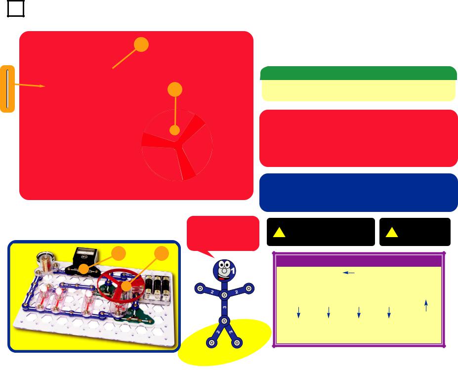
Build the circuit shown by placing all the parts with a black 1 next to them on the clear plastic base grid first. Then, assemble parts marked with a 2, and finally the parts marked with a 3. Be sure to place the motor (M1) with the
(+) side oriented as shown. Place the iron core rod into the electromagnet (M3) as shown, set the meter (M5) to the 1A scale, place the fan on the motor, and install three (3) “AA” alkaline batteries (not included) into the battery holder (B3).
Operation
Depending on the position of the slide switches (S5), the fan will spin, and in rare cases, fly into the air. Do not lean over the fan when it is spinning. Pushing the press switch (S2) will attract the compass to the electromagnet (M3).
You may need to give the fan a push with your finger to get it started.
Snappy says: electronics can be lots of fun!
1A
+
|
! |
|
WARNING: Moving parts. |
|
|
|
! |
|
WARNING: |
|
||||||||||
|
|
Do |
not touch the fan or |
|
|
|
|
Do not lean |
|
|||||||||||
|
|
|
motor during operation. |
|
|
|
|
|
|
|
over the motor. |
|
||||||||
|
|
|
|
|
|
|
|
|
|
|
|
|
|
|
|
|
||||
|
|
|
|
|
|
|
|
|
|
|
|
|
|
|
|
|
|
|
|
|
|
Educational Corner: |
|
|
|
|
|
|
|
|
|
|
|
|
|
||||||
|
This diagram is a simplified |
|
|
|
|
|
|
|
|
|
|
|
|
|
||||||
|
drawing of the circuit, with the |
|
|
|
|
|
|
|
|
|
|
|
|
|
||||||
|
components represented by |
|
|
|
|
|
|
|
|
|
|
|
|
|
|
|||||
|
symbols |
(the symbols |
are |
|
|
|
|
|
|
|
|
|
|
|
|
|
||||
|
explained on pages 4-6). |
|
|
|
|
|
|
|
|
|
|
|
|
|
|
|||||
|
Engineers use these diagrams, |
|
|
|
|
|
|
|
|
|
|
|
|
|
|
|||||
|
|
|
|
|
|
|
|
|
|
|
|
|
|
|
||||||
|
called |
schematics, |
because |
|
|
|
|
|
|
|
|
|
|
|
|
|
||||
|
|
|
|
|
|
|
|
|
|
|
|
|
|
|||||||
|
drawing |
pictures |
of |
their |
|
|
|
|
|
|
|
|
|
|
|
|
|
|||
|
circuits takes too much time |
|
|
|
|
|
|
|
|
|
|
|
|
|
||||||
|
and the connections are often |
Electric Paths |
|
|||||||||||||||||
|
unclear. |
|
|
|
|
|
||||||||||||||
|
|
|
|
|
|
|
|
|
|
|
|
|
|
|
|
|
|
|
|
|
|
|
|
|
|
|
|
|
|
|
|
|
|
|
|
|
|
|
|
|
|
-10-

|
|
|
Project #2 |
|
parallel play |
||||
|
|
|
|||||||
|
|
|
|||||||
|
|
|
|
|
|
|
|
|
|
|
|
|
|
|
|
|
|
|
Assembly |
|
|
|
|
|
|
|
|
|
Build the circuit as shown. Set the meter (M5) to the 5V |
|
|
|
|
|
|
|
|
|
scale. |
|
|
|
|
|
|
|
|
|
|
|
|
|
|
|
|
|
|
|
Operation |
|
|
|
|
|
|
|
|
||
|
|
|
|
|
|
|
|
|
Set the right slide switch (S5) to “C” to turn on the circuit. |
|
|
+ |
|
The meter (M5) measures the voltage. The compass is |
|||||
|
|
|
attracted to the electromagnet (M3). The left slide switch |
||||||
|
|
|
|
|
|
|
|
|
(S5) can bypass the bottom lamp. Pushing the press switch |
|
|
|
|
|
|
|
|
|
(S2) will spin the fan. |
|
|
|
|
|
|
|
|
|
|
|
|
|
|
|
|
|
|
|
Description |
|
|
|
5V |
|
This circuit spreads the electricity from the batteries into |
||||
|
|
|
|
|
|
|
|
|
four parallel sub-circuits to do different things. Connecting |
|
|
|
|
|
|
|
|
|
electrical components in parallel means they are between |
|
|
|
|
|
|
|
|
|
the same points in a circuit. You will learn about parallel |
|
|
|
|
|
|
|
|
|
circuits later. |
|
|
|
|
|
|
|
|
||
|
|
|
|
|
|
|
|
|
|
+
5V
-11-
Snappy says: electricity can be used to do lots of different tasks at once.
WARNING: Moving parts. |
WARNING: |
! Do not touch the fan or |
! Do not lean |
motor during operation. |
over the motor. |
Educational Corner:
Electronics is the science of working with and controlling electricity.
Electric Paths


 Project #3
+
1A
Snappy says: switches are used all over electronics - try to count how many are in your home!
+
1A
wicked switches
Assembly
Build the circuit as shown. Set the meter (M5) to the 1A scale.
Operation
Push the press switch (S2) to turn on the circuit. Flip the slide switches (S5) and see what happens. You may need to give the fan a push with your finger to get it started.
Description
The slide switches direct the electricity between the different circuit paths (each has a lamp).You will learn more about switches later.
WARNING: Moving parts. |
WARNING: |
! Do not touch the fan or |
! Do not lean |
motor during operation. |
over the motor. |
|
|
Educational Corner:
Switches are used to turn electrical appliances on or off, or to change electrical connections.
The light in your refrigerator is activated by a switch. Each of the buttons on your computer keyboard controls a switch, and there are several switches in the computer’s mouse.
Electric Paths
-12-
Project #4 |
Spinning Cylinder |
||
|
|
1A |
Suspender |
|
|
|
|
|
|
|
Assembly |
|
|
|
|
+ |
Build the circuit as shown. Set the meter (M5) to the 1A |
||
scale. Drop the thin rod into the electromagnet. |
|||
|
|
|
|
|
|
|
Operation |
|
|
|
|
|
|
Set the right slide switch (S5) to “C” to turn on the circuit. |
|||
|
|
|
The thin rod gets suspended in mid-air by the |
|||
|
|
|
electromagnet. The left slide switch (S5) selects whether |
|||
|
|
|
the lamps or motor are on. |
|
|
|
|
|
|
Description |
|
|
|
|
|
|
The thin rod is held in the air by electromagnetism, which |
|||
|
|
|
you will learn more about later. |
|
|
|
|
|
Snappy says: |
|
WARNING: Moving parts. |
|
WARNING: |
|
|
it seems like magic, |
! |
! |
||
|
|
Do not touch the fan or |
Do not lean |
|||
|
|
but it’s |
||||
|
|
|
motor during operation. |
|
over the motor. |
|
|
+ |
electromagnetism! |
|
|
||
|
|
|
|
|
||
1A |
|
Educational Corner: |
|
|
||
|
|
|
|
|
||
|
|
|
|
Electric Paths |
|
|
-13-

Project #5 |
Electricity You Can Wear |
Find some clothes that cling together in the dryer, and try to uncling them.
Rub a sweater (wool is best) and see how it clings to other clothes.
The crackling noise you hear when taking off a sweater is static electricity. You may see sparks when taking one off in a dark room.
Educational Corner:
Did you ever wonder why clothes cling together when they come out of the dryer? Did you ever hear a crackling sound when you take off a sweater? (If the room is dark you might even see sparks.) Did you ever feel a “zap” when you touch someone wearing a sweater on a dry day? These effects are caused by electricity. We call this static electricity because the electrical charges are not moving, although pulling clothes apart sounds like static on a radio. When electricity is moving (usually through wires) to do something in another place, we call it an electric current.
Electricity is an attraction and repulsion of particles in a material. All materials are made up of atoms, which
are really, really tiny. Atoms have a nucleus (which has positive electrical charges), which is surrounded by tiny electrons (negative electrical charges). When you rub a material, electrons can move on or off the atoms, giving them an electrical charge.
Photo courtesy of: NOAA Photo Library, NOAA Central Library; OAR/ERL/National Severe Storms Laboratory (NSSL) [via pingnews].
Electricity exists everywhere, but is so well balanced, that you seldom notice it. But, sometimes differences in electrical charges build up between materials, and sparks can fly. Lightning is the same effect as the sparks between clothes, but on a much greater scale. A cloud holds static electricity just like a sweater.
Why do you often “see” lightning before
you “hear” it? It is because light travels faster than sound.
|
|
|
|
|
|
– |
|
|
Electrons |
||||||
|
|
Nucleus |
|||||
– |
|
|
|
|
|
|
|
|
|
+ |
|
|
|
|
|
|
|
|
|
|
|
|
|
|
|
|
+ |
+ |
|
– |
|
|
|
+ + |
|
|
|||
– –
–
–
This diagram shows the structure of an atom, except that the nucleus and electrons are actually much farther apart.
Note: This project works best on a cold dry day. If the weather is humid, the water vapor in the air allows the static electric charge to dissipate, and this project may not work.
Snappy says: clothes can cling together because electricity is all around us.
-14-

 Project #6 Electricity in Your Hair
Assembly
You need a comb (or a plastic ruler) and some paper for this project. Rip up the paper into small pieces.
Note: This project works best on a cold dry day. If the weather is humid, the water vapor in the air allows the static electric charge to dissipate, and this project may not work.
Operation
Run the comb through your hair several times then hold it near the paper pieces to pick them up. You can also use a pen or plastic ruler, rub it on your clothes (wool works best).
Description
Rubbing the comb through your hair pulls extremely tiny charged particles from your hair onto the comb. These give the comb a static electrical charge, which attracts the paper pieces.

 Educational Corner:
Iron filings are strongly attracted to the magnet.
Iron filings are weakly attracted to the comb.
Do you want to learn more?
Hold your magnet near the paper pieces; nothing happens.
Run the comb in your hair again and place it next to the iron filings case; not much happens (there may be a weak attraction). Now hold the magnet near the iron filings; they jump to it easily.
What’s happening?
Running the comb through your hair builds up an electric charge in it, which is different from the magnetic charge in the magnet. The paper pieces are attracted to an electric charge, while the iron filings are attracted to a magnetic charge.
You will learn more about the differences between electricity and magnetism later.
Snappy says: notice how your hair can “stand up” or be attracted to the comb when the air is dry. Wetting your hair dissipates the static charge.
-15-

|
|
Project #7 |
|
|
|
|
|
Bending Water |
||||||
|
|
|
|
|
|
|
||||||||
|
|
|
|
|
|
|
||||||||
|
|
|
|
|
|
|
|
|
|
|
|
|
||
|
|
|
|
|
|
|
Assembly |
|
|
|
|
|||
|
|
|
|
|
|
|
|
|
|
|
||||
|
|
|
|
|
|
|
You need a comb (or plastic ruler) and a water faucet for |
|
||||||
|
|
|
|
|
|
|
this project. |
|
|
|
|
|
||
|
|
|
|
|
|
|
|
|
|
|
|
|
||
|
|
|
|
|
|
|
Operation |
|
|
|
|
|||
|
|
|
|
|
|
|
Run the comb through your hair several times then hold it |
|
||||||
|
|
|
|
|
|
|
next to a slow, thin stream of water from a faucet. The water |
|
||||||
|
|
|
|
|
|
|
||||||||
|
|
|
|
|
|
|
will bend towards it.You can also use a plastic ruler. Rub it |
|
||||||
|
|
|
|
|
|
|
on your clothes (wool works best). |
|
||||||
|
|
|
|
|
|
|
|
|
|
|
|
|
||
|
|
|
|
|
|
|
Description |
|
|
|
|
|||
|
|
|
|
|
|
|
Rubbing the comb through your hair builds up a static |
|
||||||
|
|
|
|
|
|
|
electrical charge on it, which attracts the water. |
|
||||||
|
|
|
|
|
|
|
||||||||
|
|
|
|
|
|
|
|
|
|
|
|
|
||
|
|
|
|
|
|
|
|
|
|
|
|
|
|
|
|
|
|
|
|
|
|
|
|
|
|
|
|
|
|
|
Educational Corner: |
|
|
|
|
|
Note: This project works best on a cold dry |
|||||||
|
|
|
|
|
|
|
|
|
|
day. If the weather is humid, the water vapor |
||||
|
Static electricity was discovered more than 2,500 years ago |
|
|
|
|
|
||||||||
|
|
|
|
|
|
in the air allows the static electric charge to |
||||||||
|
when the Greek philosopher Thales noticed that when amber (a |
|
|
|
|
|
||||||||
|
|
|
|
|
|
dissipate, and this project may not work. |
||||||||
|
hard, clear, yellow-tinted material) is rubbed, light materials like |
|
|
|
|
|
||||||||
|
|
|
|
|
|
|
|
|
|
|
||||
|
feathers stick to it. Electricity is named after the Greek word for |
|
|
|
|
|
|
|
|
|
|
|||
|
amber, which is electron. |
|
|
|
|
|
|
|
|
|
|
|||
|
|
|
|
|
|
Snappy |
says: |
big |
|
|
||||
|
Other facts about Static Electricity: |
|
|
|
|
|
|
|||||||
|
|
|
|
|
|
planes can build up a |
|
|
||||||
|
|
|
|
|
|
|
|
|
|
|
||||
|
1. Static electricity in the atmosphere causes the “static” (erratic |
|
|
|
|
|
large static charge in |
|
||||||
|
|
noises) you hear on your AM radio when reception is poor. |
|
|
|
|
|
flight. |
They |
are |
|
|||
|
2. Static Electricity can damage some types of sensitive |
|
|
|
|
|
usually connected to |
|
||||||
|
|
|
|
|
|
something like |
a |
|
|
|||||
|
|
electronic components. Electronics manufacturers protect |
Anti-Static Wrist Strap |
|
|
|
||||||||
|
|
|
|
lightning rod as soon |
|
|
||||||||
|
|
against this using static-dissipating wrist straps, floor mats, |
|
|
|
|
|
|
||||||
|
|
|
|
|
|
|
as they land. |
|
|
|
||||
|
|
and humidity control. Your Snaptricity® parts will not be |
|
|
|
|
|
|
|
|
||||
|
|
damaged by static. |
|
|
|
|
|
|
|
|
|
|
||
|
|
|
|
|
|
|
|
|
|
|
|
|||
|
3. Some homes have “lightning rods”, which are metal bars |
Lightning Rod |
|
|
|
|
|
|
|
|||||
|
|
from the roof to the ground. These help protect the home by |
|
|
|
|
|
|
|
|
|
|
||
|
|
encouraging lightning to go through the the rods instead of |
|
|
|
|
|
|
|
|
|
|
||
|
|
the house. |
|
|
|
|
|
|
|
|
|
|
||
|
|
|
|
|
|
|
|
|
|
|
|
|
|
|
-16-

Project #8 Note: This project works best on a cold dry day. If the weather is humid,
the water vapor in the air allows the static electric charge to dissipate, and this project may not work.
More Static Tricks
Snappy says: how well a material can hold an electric or magnetic charge depends on the characteristics of the material.
Take a piece of newspaper or other thin paper and rub it vigorously with a sweater or pencil. It will stick to a wall.
Cut the paper into two long strips, rub them, then hang them next to each other. See if they attract or repel each other.
If you have two balloons, rub them to a sweater and then hang the rubbed sides next to each other. They repel away.You could also use the balloons to pick up tiny pieces of paper.
Educational Corner:
Electricity vs. Gravity:
Electricity is immensely more powerful than gravity (gravity is what causes things to fall to the ground when you drop them). However electrical attraction is so completely balanced out that you don’t notice it, while gravity’s effects are always apparent because they are not balanced out.
Gravity is actually the attraction between objects due to their weight (or technically, their mass). This effect is extremely small and can be ignored unless one of the objects is as big as a planet (like the earth). Gravity attraction never goes away and is seen every time you drop something. Electrical charge, though usually balanced out perfectly, can move around and change quickly.
For example, you have seen how clothes can cling together in the dryer due to static electricity. There is also a gravity attraction between the sweaters, but it is always extremely small.
In many photocopiers, a drum is charged with static electricity. Light from the white areas of the document being copied destroys the charge, but dark areas of the document leave a pattern of charge on the drum. Toner (a powder) is attracted to the charged areas, creating an image. The toner is then transferred to paper and melted on.
2. Light |
from white |
1. Corona wire charges |
areas of |
document |
drum with static electricity |
being copied destroys |
|
|
the charge. |
|
|
|
|
5. Heated rollers |
Electricity |
Gravity |
bond toner image |
to paper. |
||
|
3. Toner from roller is attracted |
4. Toner image transfers |
|
to the charged areas. |
to charged paper. |
-17-

Project #9 |
Light the Way |
Assembly
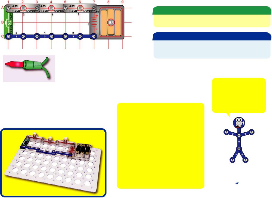
Build the circuit shown by placing all the parts with a black 1 next to them on the clear plastic base grid first. Then, assemble parts marked with a 2. Screw a bulb into the lamp socket (L4) and install three (3) “AA” batteries (not included) into the battery holder (B3).
Operation
This circuit is just like a lamp in your home, when you flip the switch (S5) to on (position B), the lamp (L4) will be on.
Educational Corner:
What is really happening here?
The batteries (B3) convert chemical energy into electrical energy and “push” it through the circuit, just like the electricity from your power company. A battery pushes electricity through a circuit just like a pump pushes water through a pipe.
The snap wires (the blue pieces) carry the electricity around the circuit, just like wires carry electricity around your home. Wires carry electricity just like pipes carry water.
The slide switch (S5) controls the electricity by turning it on or off, just like a light switch on the wall of your home. A switch controls electricity like a faucet controls water.
4.The lamp (L4) converts electrical energy into light, it is the same as a lamp in your home except smaller. In a light bulb, electricity heats up a high-resistance wire until it glows. A light bulb shows how much electricity is flowing in a circuit like a water meter shows how fast water flows in a pipe.
The base grid is a platform for mounting the circuit, just like how wires are mounted in the walls of your home to control the lights.
Comparing Electric |
|
|
Snappy says: touch the light |
||
Flow to Water Flow: |
|
|
and feel how warm it is. Only |
||
|
|
about 5% of the electricity is |
|||
|
|
|
|
||
Electric Paths |
|
|
converted into light, the rest |
||
Valve |
|||||
becomes heat. Don’t touch light |
|||||
|
|
|
Pump |
bulbs in your home because |
|
|
|
|
|||
|
|
|
they can be very hot. |
||
|
|
|
|
|
|
|
|
|
|
|
|
Water Meter
-18-

Project #10 |
Flip It |
Snappy says: the current carrying capacity of a switch depends on the contact material, size, and the pressure between the contacts.
Assembly
Build the circuit shown.
Operation
The slide switch (S5) directs the electricity to either of two paths (both lamps here). It is like many switches in your home, controlling different lights in the same area.
Variant
Replace the 3-snap wire with the press switch (S2). Now either lamp (L4) is only on when S2 is pressed.
Educational Corner:
The slide and press switches included in Snaptricity® are simple switches, more complex types are also available. Switches come in almost every shape and size imaginable. There are membrane, rocker, rotary, DIP, push button, and momentary types just to name a few.
Push Button |
Rotary |
Rocker |
Slide |
Computer |
Selector Switch |
Tools |
Toys, |
Keyboards |
on Appliances |
|
Household |
|
|
|
Items |
Very often, a single switch is used to make many different connections. The combinations of connections for a switch are indicated in the symbol for it. Here are some examples:
Rotary Switch |
Slide Switch |
Schematic |
Schematic |
Electric Paths
The “on” position of a switch is also called the “closed” position. Similarly, the “off” position is also called the “open” position. This is because the symbol for a slide switch is similar to the symbol for a door in an architect’s drawing of a room:
 Walls
Walls 
Door
The electronics symbol for a slide switch should be thought of as a door to a circuit, which swings open when the switch is off. The “door” to the circuit is closed when the switch is on. This is shown here:
Open Switch (turned off) |
Closed Switch (turned on) |
Your S5 switch has 2 positions, so it has a different symbol:
Left switch position closed
(turned on)
Right switch position open
(turned off)
Left switch position open 
(turned off)
Right switch position closed
(turned on)
-19-
Project #11 |
Pushing Electricity |
5V
Snappy says: the battery voltage drops when the lamp is connected because the batteries have trouble supplying as much electricity as the lamp would like. Remember that a battery produces electricity from a chemical reaction. Not only is there a limited amount of the chemicals in a small battery (batteries slowly get weaker as you use them), but also not all of the material can react together at the same time.
Assembly
Build the circuit and connect the red jumper wire as shown. Set the meter (M5) to the 5V setting and the slide switch (S5) to position C at first.
Operation
Read the battery voltage on the meter (the top scale), it should be about 4.5V. The lamp will be off.
Flip the switch to position B; the lamp lights and the voltage drops a little. (To learn why the voltage drops now, ask Snappy.)
Move the red jumper wire from position A on the switch to position B. The battery voltage is the same here because none is lost across the switch.
Now flip the switch to position C (OFF); the voltage at the lamp drops to zero and it shuts off.
Educational Corner:
Electricity is the movement of sub-atomic charged particles (electrons) through a material due to electrical pressure across the material, such as from a battery.
The electrical pressure exerted by a battery or other power source is called voltage and is measured in volts (V, and named after Alessandro Volta who invented the battery in 1800). Notice the “+” and “–” signs on the battery. These indicate which direction the battery will “pump” the electricity.
Circuits need the right voltage to work properly. For example, if the electrical pressure to a lamp is too low, then the bulb won’t turn on; and if too high, then the bulb will overheat and burn out.
The electric current is a measure of how fast electricity is flowing in a wire, just as the water current describes how fast water is flowing in a pipe. It is expressed in amperes (A, named after Andre Ampere who studied the relationship between electricity and magnetism) or
milliamps (mA, 1/1000 of an ampere).
5V
Record the voltage you measured here, it will be used in project 13:
-20-


 Project #12
+
5V
Snappy says voltage is sometimes called electro- motive-force (EMF) because it pushes the electrons through the circuit.
 +
+
5V
Pushing a Lot of Electricity
WARNING: Moving parts. Do not touch
!the fan or motor during operation.
WARNING: Do not
!lean over the motor.
Assembly
Build the circuit as shown; it is the same as the preceding one except the lamp (L4) was replaced by the motor (M1). Set the meter (M5) to the 5V setting and the slide switch (S5) to position C at first.
Operation
Read the battery voltage on the meter (the top scale), it should be about 4.5V. Flip the switch to position B; the fan spins and the voltage drops - more than it did with the lamp.
Turn off the circuit and remove the fan. Turn the switch back on and read the voltage; it doesn’t drop as much without the fan.
Description
It takes a lot of current to spin the fan as fast as it would like to go, and the batteries can’t produce enough. As a result, the voltage (electrical pressure) from the batteries drops.
It’s a lot easier to spin the motor shaft without the fan on it, so the voltage doesn’t drop much without the fan.
Educational Corner:
Wires can generally be as long as desired without affecting performance, just as using garden hoses of different lengths has little effect on the water pressure as you water your garden. However there are cases where the length and size of a pipe does matter, such as in the water lines for your city. Similarly, wire length and size are important for electric power lines transporting electricity from a power plant in a remote area to a city.
Batteries are made from materials like zinc and magnesium dioxide, electricity flows as these react with each other. As more material is used up by the reaction, the battery voltage is slowly reduced until eventually the circuit no longer functions and you have to replace the batteries. Some batteries, called rechargeable batteries (such as the batteries in your cell phone), allow you to reverse the
chemical reaction using another electric source.
-21-


 Project #13
1A
Snappy says: the Ω symbol is the last letter in the Greek alphabet and is pronounced Omega.
1A
What’s An Ohm?
Assembly
Build the circuit shown. Set the meter (M5) to the 1A setting.
Operation
Set the slide switch (S5) to position B to measure the current through the lamp (L4).
Educational Corner:
The resistance of a circuit represents how much it resists the electrical pressure (voltage) and limits the flow of electric current. The relationship between voltage, current, and resistance is the most important one in electronics. It is known as Ohm’s Law (after George Ohm who
discovered it in 1828):
Voltage
Current =
Resistance
When there is more resistance, less current will flow unless you increase the voltage. Resistance is measured in ohms. The symbol used for an ohm is Ω.
Using the voltage measurement you made in project 11 and the current measurement you made here, you can calculate the resistance of the lamp. It is usually 15-20 ohms.
The other parts in the circuit (switch, meter on 1A scale, blue snap wires, and batteries) also have resistance but these are much smaller.
Note: Your actual results may vary. Your M5 meter is a simple meter; don’t expect it to be as accurate as normal electronic test instruments.
What is Resistance? Take your hands and rub them together very fast. Your hands should feel warm. The friction between your hands converts your effort into heat. Resistance is the electrical friction between an electric current and the material it is flowing through; it is the loss of energy from electrons as they move through the material.
The “power” of electricity is a measure of how fast energy is moving through a wire. It is expressed in Watts (W, after James Watt for his work with engines). It is a combination of the electrical voltage (pressure) and current:
Power = Voltage x Current
OR
Voltage x Voltage
Power =
Resistance
= Current x Current x Resistance
Using the voltage and current measurements you made, you can calculate the power of the lamp. It should be about 1 watt. Compare this to the light bulbs in your home, which are usually about 40-100 watts.
Electric
Paths
-22-


 Project #14
? |
1A
Snappy says: the best conductor ever discovered is silver, which is very expensive. Copper is the second best conductor, and it is used in almost all electrical wires.
1A
Be A Scientist
Assembly
Build the circuit shown, the ? can be anything you want. Set the meter (M5) to the 1A setting.
Operation
Turn on the slide switch (S5, position B) and touch various materials between the snaps on the switch and meter. See which materials are good at transporting electricity by watching the meter current and lamp (L4) brightness. Try string, the electrodes, a shirt, plastic, paper, two of your fingers, wood, or anything in your home.
If the meter reads zero, switch it to the 1mA setting to see if there is just a very small current. To help protect the meter, always switch back to the 1A scale before testing a new circuit.
Educational Corner:
Some materials, such as metals, have very low resistance to electricity will make the lamp bright and give a large current measurement on the meter. These materials are called conductors. Conductors have electrons that are loosely held to the nucleus and can move easily.
Other materials, such as paper, air, and plastic, have very high resistance to electricity. These will turn off the lamp and give a zero current measurement on the meter even in the 1mA setting. These materials are called insulators. Insulators have their electrons locked in tight and have no room for more.
Did you ever hear the term “blown fuse”? Some special wires are designed to break when an unexpectedly high current flows through them. These are called fuses.
This wire melts to break the circuit.
Fuses are designed to shut down a circuit when something is wrong, such as a component failure, bad design, or a person using it improperly. This shutdown prevents further damage to the circuit, and can prevent explosions or fires.
Fuses are important for safety and most electrical products have one, especially if they use electricity supplied by your local electric company. Small battery-powered products usually do not have them because the batteries are not powerful enough to cause harm.
Some fuses need replaced after “blow”, but others can be reset by flipping a switch. Every home has an electrical box of resetable fuses, it may look like this:
-23-


 Project #15
1mA
1mA
Make Your Own Parts
Assembly
Build the circuit shown, set the meter (M5) to the 1mA setting.
Operation
Make your parts using either the water puddles method (A), the drawn parts method (B), or the pencil parts method (C). Set the slide switch (S5) to position B to turn on the circuit. Touch the metal in the jumper wires to your parts and read the current in milliamps.
Method A (easy): Spread some water on the table into puddles of different shapes, perhaps like the ones shown below. Touch the jumper wires to points at the ends of the puddles.
Method B (challenging): Use a SHARP pencil (No. 2 lead is best) and draw shapes, such as the ones here. Draw them on a hard, flat surface. Press hard and fill in several times until you have a thick, even layer of pencil lead. Touch the jumper wires to points at the ends of the drawings. You may get better electrical contact if you wet the metal with a few drops of water. Wash your hands when finished.
Method C (adult supervision and permission required): Change the setting on the meter to the 1A scale. Use some double-sided pencils if available, or VERY CAREFULLY break some pencils in half. Touch the jumper wires to the black core of the pencil at both ends.
Educational Corner:
You can use Ohm’s Law to measure the resistance of your puddles and drawings. The voltage is about 4.5V, and use the current measured on the meter.
Voltage
Resistance =
Current
The black core of pencils is graphite, the same material used in resistor components throughout the electronics industry.
Snappy says: long narrow shapes have more resistance than short wide ones.
-24-


 Project #16
1mA
Snappy says: Pure water has very high
resistance because its atoms hold their electrons tightly and have no room for more. Impurities (such as dissolved dirt, minerals, or salt) decrease the resistance because their atoms have loose electrons, which make it easier for other electrons to move through.
1mA
Hydro-Resistors
Assembly
Build the circuit shown. Set the meter (M5) to the 1mA setting. Add about 1/4 inch of water to a cup or bowl. Connect the jumper wires and place them in the water, make sure the metal parts aren’t touching each other. Set the slide switch (S5) to position B to turn the circuit on.
Operation
Measure the current through the water.
Add salt to the water and stir to dissolve it. The current should be higher now (if not already at full scale), since salt water has less resistance than plain water.
Now add more water to the cup and watch the current.
If you have some distilled water, place the jumper wires in it and measure the current.You should measure close to zero current, since distilled (pure) water has very high resistance. Normal water has impurities which lower its resistance. Now add salt to the distilled water and watch the current increase as the salt dissolves!
You can also measure the current through other liquids.
Don’t drink any water or liquids used here.
Educational Corner:
Depending on your local water supply, |
In the 5V setting, the water resistance |
your current measurement may |
is compared to the internal resistance |
exceed the 1mA scale.You can switch |
of the meter. A low reading means the |
the meter to the 5V scale to get a |
water has relatively high resistance. A |
better comparison, though it isn’t |
high reading of 4V or more means the |
really a voltage measurement. |
water has relatively low resistance. |
-25-
|
|
|
Project #17 |
|
|
|
|
One Way Around |
|
||||||||
|
|
|
|
|
|
||||||||||||
|
|
|
|
|
|
||||||||||||
|
|
|
|
|
|
|
|
|
|
|
|
|
|
|
|
|
|
|
|
|
|
|
|
|
|
|
|
|
|
|
|
|
|
|
|
|
|
|
|
|
|
|
|
|
|
|
|
Assembly |
|
|
|
|
|
|
|
|
|
|
|
|
|
|
|
|
|
Build the circuit and push the press switch (S2). The lamps |
|
||||
|
|
|
|
|
|
|
|
|
|
|
|
(L4) are all on, but are dim. |
|
|
|
|
|
|
|
|
|
|
|
|
|
|
|
|
|
|
|
|
|
|
|
|
|
|
|
|
|
|
|
|
|
|
|
Description |
|
|
|
|
|
|
|
|
|
|
|
|
|
|
|
|
|
The three lamps are connected in a series. They are dim |
|
||||
|
|
|
|
|
|
|
|
|
|
|
|
|
|||||
|
|
|
|
|
|
|
|
|
|
|
|
because the voltage from the batteries (B3) is divided |
|
||||
|
|
|
|
|
|
Most strings will still work if |
|
|
|
|
|
between them. |
|
|
|
|
|
|
|
|
|
|
|
|
|
|
|
|
|
|
|
|
|
|
|
|
|
|
|
|
|
one bulb burns out because a |
|
|
|
|
|
|
|
|
|
|
|
|
|
|
|
|
|
special heat-activated bypass |
|
|
|
|
|
|
|
|
|
|
|
|
|
|
|
|
|
Educational Corner: |
|
|
|
|
|||||||
|
|
|
|
|
|
wire is built into each bulb. |
|
|
|
|
|
||||||
|
|
|
|
|
|
When the bulb burns out, the |
|
|
|
|
|
|
|
|
|
|
|
|
|
|
|
|
|
Connecting parts in series is one way of arranging |
|
|
|
|
|||||||
|
|
|
|
|
|
full house voltage is across |
|
Snappy says: the 0V or “–” |
|
||||||||
|
|
|
|
|
|
|
|
||||||||||
|
Strings of Christmas lights are |
the bypass wire, which heats |
|
them in a circuit. The advantage of it is that wiring |
|
||||||||||||
|
|
side of the battery is often |
|
||||||||||||||
|
little low-voltage lamps |
it until it turns on. Sometimes |
|
them together is simple. The disadvantage is that if |
|
||||||||||||
|
|
referred to as “ground”, |
|
||||||||||||||
|
connected in series to the |
only half the bulbs in a string |
|
one lamp breaks, all three will be off. |
|
||||||||||||
|
house power (120V). |
They |
are lit. This is because some |
|
|
|
|
|
|
|
since in house or building |
|
|||||
|
are inexpensive, but |
if one |
long strings are actually two |
|
|
|
|
|
|
|
wiring it is connected to a rod |
|
|||||
|
bulb falls out, then the entire |
|
|
|
|
|
|
|
in the ground as protection |
|
|||||||
|
(or more) shorter strings |
|
In this circuit the lamps are the resistances |
|
|||||||||||||
|
string will be off. |
|
|
connected in parallel. |
|
which are limiting the flow of electricity. Placing |
against lightning. |
|
|||||||||
|
|
|
|
|
|
|
|
||||||||||
|
|
|
|
|
|
|
|
|
|
|
|
||||||
|
|
|
|
|
|
|
|
resistances in series increases the total |
|
|
|
|
|||||
|
|
|
|
|
|
|
|
|
|
|
|
||||||
|
|
|
|
|
|
|
|
resistance. Advanced users can compute the |
|
|
|
|
|||||
|
|
|
|
|
|
|
|
total resistance as follows: |
|
|
|
|
|
||||
|
|
|
|
|
|
|
|
|
Rseries = R1 + R2 + R3 + . . . |
|
|
|
|
||||
|
|
|
|
|
|
|
|
The current is the same through all the |
|
|
|
|
|||||
|
|
|
|
|
|
|
|
resistances in a series circuit. Ohm’s Law says |
|
|
|
|
|||||
|
|
|
|
|
|
|
|
that Voltage equals Current times Resistance, so |
|
|
|
|
|||||
|
|
|
|
|
|
|
|
the highest resistances in a series circuit will |
|
|
|
|
|||||
|
|
|
|
|
|
|
|
have the largest voltage drop across them. |
|
|
|
|
|||||
|
|
|
|
|
|
|
|
Equal resistances will have the same voltage |
Electric Paths |
|
|||||||
|
|
|
|
|
|
|
|
drop. In other words: |
|
|
|
|
|
||||
|
|
|
|
|
|
|
|
Voltage (across one resistor) = |
Resistance (of that resistor) |
x Voltage |
|
|
|
|
|||
|
|
|
|
|
|
|
|
|
Resistance |
|
|
|
|
||||
|
|
|
|
|
|
|
|
|
|
|
|
(total applied to the series circuit) |
|
|
|
|
|
|
|
|
|
|
|
|
|
|
|
|
|
|
|
|
|||
|
|
|
|
|
|
|
|
|
|
|
|
(total of resistors in the circuit) |
|
|
|
|
|
|
|
|
|
|
|
|
|
|
|
|
|
|
|
|
|
|
|
|
|
|
|
|
|
|
|
|
|
|
|
|
|
|
|
|
|
|
|
|
|
|
|
|
|
|
|
|
|
|
|
|
|
|
|
-26-


 Project #18
Snappy says: most of the lights in your house are connected in parallel; so if one bulb burns out then the others are not affected.
Many Paths
Assembly
Build the circuit and push the press switch (S2). The lamps (L4) are all bright.
Description
The three lamps are connected in parallel with one another. They are bright because each lamp gets the full battery voltage. The voltage pushes the current with equal force, because all are 4.5V, down each path.
Educational Corner:
Connecting parts in parallel is another way of arranging them in a circuit. The advantage of it is that if one burns out, the others will still work (unscrew one of the bulbs to prove this). The disadvantage is that wiring the parts together is more complex than with series circuits.
All large circuits are made of combinations of series and parallel circuits.
In this circuit the lamps are the resistances which are |
1 |
|
1 |
|
1 |
|
1 |
|
limiting the flow of electricity. Placing resistances in |
|
= |
|
+ |
|
+ |
|
+ . . . . |
|
|
|
|
|||||
parallel decreases the total resistance. Advanced |
Rparallel |
|
R1 |
R2 |
R3 |
|||
users can compute the total resistance as follows: |
|
|
|
|
|
|
|
|
The voltage is the same across all the resistances in a parallel circuit. Ohm’s Law says that Voltage equals Current times Resistance, so the lowest resistances in a parallel circuit will
have the most current through them. Equal resistances will have the same current. In other |
|||
words: |
|
Resistance |
|
|
|
|
|
|
Current (through one branch) = |
(total in all OTHER parallel branches) |
x Current |
|
|
||
|
Resistance |
||
|
|
(total applied to the parallel circuit) |
|
(total of resistors in all branches)
Electric Paths
-27-
 Loading...