


TRANSONIC
SERVICE MANUAL
T C 1 6 3 1 T V
1.Caution……………………………………………………………2
2.Specification………………………………………………………6
3.BOM List ……………………… …………………….................13
4.Alignment Procedure………………………………………….…33
5.Block Diagram……………………………………………………40
6.Schematic Diagram………………………………………………41
7.PCB Layout………….……………………………………………42
8.Explode View Diagram……………………………………………43
This manual is the latest at the time of printing, and does not include the modification which may be made after the printing, by the constant improvement of product.
CAUTION:
Use of controls, adjustments or procedures other than those specified herein may result in hazardous radiation exposure.
CAUTION
RISK OF ELECTRIC
SHOCK DO NOT OPEN.
CA UTION: TO REDUCE THE RISK OF
ELECTRICAL SHOCK, DO NOT REMOVE COVER (OR BACK). NO USER SERVICEABLE
PARTS INSIDE. REFER SER VICING TO
QUALIFIED SERVICE PERSONNEL.
The lighting flash with arrowhead symbol, with an equilateral triangle is intended to alert the user to the presence of uninsulated dangerous voltage within the products enclosure that may be of sufficient magnitude to constitute a risk of electric shock to the person.
The exclamation point within an equilateral triangle is intended to alert the user to the presence of important operating and maintenance (servicing) instructions in the literature accompanying the appliance.
WARNING: TO REDUCE RISK OF FIRE OR ELECTRIC SHOCK, DO NOT
EXPOSE THIS APPLIANCE TO RAIN OR MOISTURE.
2

IMPORTANT SAFETY INSTRUCTIONS
CAUTION:
Read all of these instructions. Save these instructions for later use. Follow all Warnings and
Instructions marked on the audio equipment.
1.Read InstructionsAll the safety and operating instructions should be read before the product is operated.
2.Retain InstructionsThe safety and operating instructions should be retained for future reference.
3.Heed WarningsAll warnings on the product and in the operating instructions should be adhered to.
4.Follow InstructionsAll operating and use instructions should be followed.
FOR YOUR PERSONAL SAFETY
1.When the power cord or plug is damaged or frayed, unplug this television set from the wall outlet and refer servicing to qualified service personnel.
2.Do not overload wall outlets and extension cords as this can result in fire or electric shock.
3.Do not allow anything to rest on or roll over the power cord, and do not place the TV where power cord is subject to traffic or abuse. This may result in a shock or fire hazard.
4.Do not attempt to service this television set yourself as opening or removing covers may expose you to dangerous voltage or other hazards. Refer all servicing to qualified service personnel.
5.Never push objects of any kind into this television set through cabinet slots as they may touch dangerous voltage points or short out parts that could result in a fire or electric shock. Never spill liquid of any kind on the television set.
6.If the television set has been dropped or the cabinet has been damaged, unplug this television set from the wall outlet and refer servicing to qualified service personnel.
7.If liquid has been spilled into the television set, unplug this television set from the wall outlet and refer servicing to qualified service personnel.
8.Do not subject your television set to impact of any kind. Be particularly careful not to damage the picture tube surface.
9.Unplug this television set from the wall outlet before cleaning. Do not use liquid cleaners or aerosol cleaners. Use a damp cloth for cleaning.
10.1.Do not place this television set on an unstable cart, stand, or table. The television set may fall, causing serious injury to a child or an adult, and serious damage to the appliance. Use only with a cart or stand recommended by the
manufacturer, or sold with the television set. Wall or shelf mounting should follow the manufacturer s instructions, and should use a mounting kit approved by the manufacturer.
10.2.An appliance and cart combination should be moved with care. Quick stops, excessive force, and uneven surfaces may cause the appliance and cart combination to overturn.
3
PROTECTION AND LOCATION OF YOUR SET
11.  Do not use this television set near water ... for example, near a bathtub, washbowl, kitchen sink, or laundry tub, in a wet basement, or near a swimming pool, etc.
Never expose the set to rain or water. If the set has been exposed to rain or water, unplug the set from the wall outlet and refer servicing to qualified service personnel.
12.Choose a place where light (artificial or sunlight) does not shine directly on the screen.
13.Avoid dusty places, since piling up of dust inside TV chassis may cause failure of the set when high humidity persists.
14.The set has slots, or openings in the cabinet for ventilation purposes, to provide reliable operation of the receiver, to protect it from overheating. These openings must not be blocked or covered.
Never cover the slots or openings with cloth or other material.
Never block the bottom ventilation slots of the set by placing it on a bed, sofa, rug, etc.
Never place the set near or over a radiator or heat register.
Never place the set in a built-in enclosure, unless proper ventilation is provided.
PROTECTION AND LOCATION OF YOUR SET
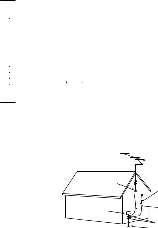
15.1.If an outside antenna is connected to the television set, be sure the antenna system is grounded so as to provide some protection against voltage surges and built up static charges, Section 810 of the National Electrical Code, NFPA No. 70-1975, provides information with respect to proper grounding of the mast and supporting structure, grounding of the lead-in wire to an antenna discharge unit, size of grounding conductors, location of antenna discharge unit, connection to grounding electrode, and requirements for the grounding electrode.
EXAMPLE OF ANTENNA GROUNDING AS PER NATIONAL ELECTRICAL CODE INSTRUCTIONS
EXAMPLE OF ANTENNA GROUNDING AS PER
NATIONAL ELECTRICAL CODE
ANTENNA
 LEADIN WIRE
GROUND CLAMP
ANTENNA DISCHARGE UNIT (NEC SECTION 810-20)
GROUNDING
 CONDUCTORS
ELECTRIC SERVICE (NEC SECTION 810-21)
EQUIPMENT
GROUND CLAMPS
POWER SERVICE GROUNDING
NEC-NATIONAL ELECTRICAL CODE ELECTRODE SYSTEM
(NEC ART 250. PART H)
15.2.Note to CATV system installer : (Only for the television set with CATV reception)
This reminder is provided to call the CATV system installer s attention to Article 820-40 of the NEC that provides guidelines for proper grounding and, in particular, specifies that the cable ground shall be connected to the grounding system of the building, as close to the point of cable entry as practical.
16.An outside antenna system should not be located in the vicinity of overhead power lines or other electric lights or power circuits, or where it can fall into such power lines or circuits. When installing an outside antenna system, extreme care should be taken to keep from touching such power lines or circuits as contact with them might be fatal.
17.For added protection for this television set during a lightning storm, or when it is left unattended and unused for long periods of time, unplug it from the wall outlet and disconnect the antenna. This will prevent damage due to lightning and power-line surges.
4

OPERATION OF YOUR SET
18.This television set should be operated only from the type of power source indicated on the marking label.If you are not sure of the type of power supply at your home, consult your television dealer or local power company. For television sets designed to operate from battery power, refer to the operating instructions.
19.If the television set does not operate normally by following the operating instructions, unplug this television set from the wall outlet and refer servicing to qualified service personnel. Adjust only those controls that are covered in the operating instructions as improper adjustment of other controls may result in damage and will often require extensive work by a qualified technician to restore the television set to normal operation.
20.When going on a holiday : If your television set is to remain unused for a period of time, for instance, when you go on
a holiday, turn the television set off  and unplug the television set from the wall outlet.
IF THE SET DOES NOT OPERATE PROPERLY
21.If you are unable to restore normal operation by following the detailed procedure in your operating instructions, do not attempt any further adjustment. Unplug the set and call your dealer or service technician.
22.Whenever the television set is damaged or fails, or a distinct change in performance indicates a need for service, unplug the set and have it checked by a professional service technician.
23.It is normal for some TV sets to make occasional snapping or popping sounds, particularly when being turned on or off. If the snapping or popping is continuous or frequent, unplug the set and consult your dealer or service technician.
FOR SERVICE AND MODIFICATION
24.Do not use attachments not recommended by the television set manufacturer as they may cause hazards.
25.When replacement parts are required, be sure the service technician has used replacement parts specified by the manufacturer that have the same characteristics as the original part. Unauthorized substitutions may result in fire, electric shock, or other hazards.
26.Upon completion of any service or repairs to the television set, ask the service technician to perform routine safety checks to determine that the television is in safe operating condition.
5
PFS (Product Functional Specification)
Date: |
|
ProductView......: |
TC1631TV |
Report by............: Linda Wen |
|
Specs / Products |
|
MasterData |
|
Customer Id |
ORIENTAL PACIFIC (NZ) LIMITED |
Version |
0.1 |
BOM No |
03-E2764H-AA36 |
Brand |
TRANSONIC |
Reception |
|
-Tuning - presets/channels |
|
100 |
x |
125 |
|
200 |
|
-Tuning - technology |
|
PLL |
x |
VST |
x |
-Tuning - Indication |
|
--- |
X |
-Freq Bands |
|
UVSH |
|
Full-Cable |
x |
-IF Freq |
|
38MHz |
|
38.9MHz |
X |
45.75MHz |
|
-TV Systems Off Air/Cable |
|
NTSC M (3.58 - 4.5) |
|
NTSC (4.43 - 5.5) |
|
NTSC (4.43 - 6.5) |
|
NTSC 3.58 |
x |
NTSC 4.43 |
x |
PAL B/G |
x |
PAL D/K |
|
PAL I |
|
SECAM B/G |
|
SECAM D/K |
|
-Add Systems Ext In |
|
NTSC 3.58 |
|
NTSC 4.43 |
|
NTSC Play Back |
x |
PAL 60 |
x |
-TV Systems Multi |
|
NTSC |
|
PAL |
x |
-Sound Systems |
|
AV Stereo |
x |
NICAM |
|
German Stereo |
|
American Stereo |
|
Korean Stereo |
|
Picture - Processing |
|
-Scan |
|
Standard |
x |
-Scan Modes |
|
4:3 |
x |
4:3 Expand |
|
-Wide Screen Switching |
|
-Combfilter |
|
-Picture Control |
|
Brightness |
x |
Colour/Hue/ tint |
x |
Contrast |
x |
Color Temperature |
|
Sharpness |
x |
scan velocity modulation |
|
LTI / CTI |
|
Smart Pict. 4 Modes |
|
Smart Pict. 5 Modes |
|
Multiplicate picture scan mode |
|
-Pict Enhancement |
|
Active Control (without LNA) |
|
Black Stretch |
x |
dynamic skin |
|
-Pict Noise Reduction |
|
NR |
x |
Page 1
PFS (Product Functional Specification)
Date: |
|
ProductView......: |
TC1631TV |
Report by............: Linda Wen |
|
Specs / Products |
|
Picture - Display |
|
-Display Type |
|
DV - CRT - Normal Flat |
x |
DV-CRT-Pure Flat |
|
DV - CRT - Super Flat |
|
-Screen Format |
|
4:3 |
x |
Expand 4:3 |
|
16:9 |
|
-Size(Visual)" - size/vis. cm |
|
14(13V) - 37/34 cm |
x |
21(20V) - 55/51cm |
|
25(00v) - 00/00cm |
|
29(27v) - 72/68cm |
|
34(00v) - 00/00cm |
|
-Deflection System (CRT only) |
|
1 Fh |
x |
2 Fh |
|
-Tube Technology (CRT only) |
|
Iron |
x |
Black Matrix |
x |
Real Flat |
|
-CRT Defl |
|
090 degr |
x |
100 degr |
|
110 degr |
|
500 degr |
|
-CRT Gun |
|
Stand Gun |
x |
-CRT Magn field |
|
Neutral |
|
S Hemisphere |
Australia South Hemisphere |
North-Neutral |
|
-Resolution |
|
-Coating (only for D.V. sets) |
|
-White Point |
|
Sound |
|
-Leaflet Power |
|
01W |
|
02W |
|
04W |
x |
06W |
|
10W |
|
12W |
|
20W |
|
-RMS Power Intern |
|
1x1W |
|
2x1W |
|
2x2W |
14" |
2x3W |
|
2x4W |
|
2x5W |
|
2X6W |
|
2X10W |
|
-RMS Power Extern |
|
-Surround Sound |
|
-Sound Features |
|
AVL |
|
Mute |
x |
Smart Sound (4 modes) |
|
-Sound Control |
|
Balance |
|
Bass |
|
Bass Boost |
|
Smart Sound 4 Modes |
|
Smart Sound 5 Modes |
|
Treble |
|
Treble Boost |
|
Volume |
x |
Sound - Speakers |
|
-Speaker configuration |
|
2x1 |
x |
Page 2
PFS (Product Functional Specification)
Date: |
|
ProductView......: |
TC1631TV |
Report by............: Linda Wen |
|
Specs / Products |
|
-Speakers used |
|
Normal Range |
x |
Full Range |
|
User Interface |
|
-Interface Name |
|
Full interface |
A30V03-TOP |
-Voice Control |
|
-Menu |
|
Cursor Control |
X |
-Menu Colours |
|
-Menu Languages |
|
Arabic |
|
Chinese - Simplified |
|
Chinese - Traditional |
|
English |
X |
Russian |
|
Malay |
|
Thai |
|
-Record Select - sources: |
|
-Special Features |
|
On/Off Timer |
x |
Sleep timer |
x |
Game |
x |
Notebook |
x |
Calendar |
x |
Auto Standby |
x |
Channel Copying |
x |
Channel Naming |
|
Channel Lock |
|
Favorite Channel |
x |
Manual Skip |
|
channel navigation |
|
Personal Zapping |
|
Signal Strength Indicator |
|
V-chip with Smart Lock |
|
Hotel Mode |
x |
Recall |
|
AT |
|
High Sensitive |
|
-Operational Features |
|
Alternate Channel |
|
Surf |
|
-PP Features |
|
One PP for all channels |
x |
-Tuning / Install Features |
|
Aut Cable/Ant. Select |
x |
Auto Channel Prog |
x |
Auto Store |
x |
Factory Mode |
x |
Fine Tuning |
x |
Language Selection |
x |
Manual Search/Store |
x |
Service Mode |
x |
-Clock/Timer Functions |
|
Sleep timer |
x |
Alarm Timer |
|
Crystal Clock |
|
Real Clock |
|
Biological Clock |
x |
-Local Controls Front |
|
Channel +- |
|
Mains Switch (Flush) |
|
Volume +- |
|
TV/AV |
|
Auto search |
|
menu |
|
-Local Controls Top |
|
Channel +- |
x |
Volume +- |
x |
TV/AV |
x |
menu |
x |
-Indicators - screen |
|
Page 3
PFS (Product Functional Specification)
Date: |
|
ProductView......: |
TC1631TV |
Report by............: Linda Wen |
|
Specs / Products |
|
-Indicators - front |
|
RC Recvd LED |
x |
SB LED |
x |
-Numb of Loc Cont (incl Mains) |
|
5 |
|
7 |
x |
-Number of Ind. (incl Mains) |
|
1 |
|
-Local Controls (Old) |
|
Remote Control |
|
-Remote Control - scope |
|
TV |
x |
-Remote Control - type |
|
Standard |
x |
-Remote Control - typenr |
|
E |
|
F |
x |
Q |
|
RC115 |
|
-Remote Control - features |
|
Connectors Rear |
|
-Scart RGB+Y/C+CVBS |
|
-Scart RGB+CVBS |
|
-Scart CVBS+Y/C |
|
-Component In (Y/U/V) Cinch |
|
Ext(1) |
x |
-Component In (YPbPr) Cinch |
|
-In Y/C+Cinch(CVBS+St) |
|
1x |
X |
-In Y/C+Cinch(CVBS+Mo) |
|
-In Y/C+Cinch(St) |
|
-In BNC (CVBS) |
|
-In Cinch(CVBS+Mo) |
|
Ext(1) |
|
-In Cinch(CVBS+St) |
|
Ext2 |
|
-In VGA |
|
-Out Y/C+Cinch(CVBS+St) |
|
-Out Cinch(CVBS+St) |
|
1x |
X |
-Out Cinch(CVBS+Mo) |
|
1x |
|
-Out Cinch Audio Stereo |
|
-Out Cinch Audio Mono |
|
-Out Cinch Dolby Surround |
|
-Out Cinch Subwoofer |
|
-Dig Audio Out |
|
-Loudspeakers |
|
-Control Busses |
|
-Feature Slot |
|
-ITV Smart Port |
|
-Terr. Antenna in |
|
75 Ohms (IEC type) |
x |
Guide + IR Blaster Jack |
|
Connectors Front |
|
-In Y/C + Cinch(CVBS+St) |
|
-In Y/C + Cinch(CVBS+Mo) |
|
-In Y/C + Cinch Stereo |
|
-In Cinch (CVBS + St) |
|
-In Cinch (CVBS+Mo) |
|
Yes |
|
-Headphone Out |
|
Mini-Jack 3.5mm |
|
-Feature Slot |
|
-Cinch A/V in |
|
Connectors Side |
|
-In Y/C + Cinch(CVBS+St) |
|
-In Y/C + Cinch Stereo |
|
-In Cinch (CVBS + St) |
|
Yes |
x |
-In Cinch (CVBS + Mo) |
|
Yes |
|
Page 4
PFS (Product Functional Specification)
Date: |
|
ProductView......: |
TC1631TV |
Report by............: Linda Wen |
|
Specs / Products |
|
-Headphone Out |
|
Mini-Jack 3.5mm |
|
-Cinch A/V in |
|
-Cinch A/V out |
|
Connectors Top |
|
-In Cinch (CVBS + St) |
|
-Headphone Out |
|
Connectors Mechanical |
|
-Headphone |
|
-Cinch A/V in/out |
|
-Cinch Component |
|
-Cinch Y/C |
|
Styling |
|
-Cabinet Name |
14276 |
-Configuration |
|
DAS |
|
Symm |
x |
-Mechanics |
|
-Speaker Visibility |
|
Standard |
X |
General |
|
-Segment |
|
Standard 4:3 |
X |
-Chassis |
M28B |
-Software Delivery Mode |
|
-Software Version |
|
-Mains Voltage |
|
110V - 270V |
|
90 - 260V |
|
90-276 AutoV |
|
160 - 260 V |
|
230 - 240 V |
X |
-Mains Frequency |
|
50Hz |
X |
-Type Mains Cord |
|
FlatPin(Non-Polarised) |
|
Australia |
SAA |
Australia / New Zealand |
|
Euro |
|
New Zealand |
|
VDE |
|
Power Consumption (P)TV in On |
70W |
Power Consumption SB in Watts |
|
Less than 1 |
X |
Less than 3 |
|
Less than 6 |
|
Less than 10 |
|
Power Consumption Semi SB in W |
|
-Power in "ON" for |
|
-Power in Standby for |
|
-Power in "OFF" for |
|
-INDICATION on BACKCOVER |
|
Made-in in Family Sheet |
X |
FCC/Elect Shock caution label |
|
Serial label |
X |
Warning label on backcover |
X |
-Channel |
|
National Org.-NO |
X |
Final Equipment |
|
-Packaging - methods |
|
2 Colour Printing |
|
Brown Carton |
|
White Carton |
|
-Documents and manuals |
|
Instruction Book (User Manual) |
x |
Adbertising Brochure |
|
Extended Warranty Brochure |
|
Guarantee Doc |
X |
Screen Sticker |
|
Approbation Labels |
X |
Easy installation Guide |
|
Plastic Bag |
X |
Page 5
PFS (Product Functional Specification)
Date: |
|
ProductView......: |
TC1631TV |
Report by............: Linda Wen |
|
Specs / Products |
|
Warning label |
X |
Warranty Card |
|
-Languages DFU |
|
Arabic |
|
English |
x |
Local Integration |
|
Malay |
|
Thai |
|
-Cables Supplied |
|
-Antenna Supplied |
|
-Stand Supplied |
|
-Aux Equipm Supplied |
|
Batteries for RC (2 x AA) |
x |
Miscellaneous |
|
-Approbation |
|
CB |
X |
EMC |
X |
-Tests |
|
-Local Integration |
|
PIP/POP |
|
-Type |
|
--- |
|
-Features |
|
Digital Reception |
|
-Transmission |
|
-Profile/Level |
|
Digital Software |
|
-Services |
|
Digital Connections |
|
-Digital Rear |
|
Built-in Data System |
|
-Text Standard |
|
No Text |
|
-(Tele)text Features |
|
1 Page text |
|
10 Page text |
|
-Nbr bacgrnd page/Mem Size |
|
-Text Technology |
|
-Digital Data handling |
|
-Program Guide |
|
Built-in Clock/Timer |
|
-Type |
|
-Features |
|
Built-in Radio |
|
-Type |
|
Built-in PC display |
|
VGA |
|
XGA |
|
SVGA |
|
SXGA |
|
WVGA |
|
UXGA |
|
-PC Synch |
|
-PC Control |
|
Built-in TV display |
|
50i |
|
60i |
|
100i |
|
60P |
|
75P |
|
Built-in Media Slots/ DVD driver |
|
-Type of Medium |
|
-Type of Deck |
|
-Version of Deck |
|
-Playback Formats |
|
-Copy Protection Compliance |
|
Phased Out Items |
|
-Tuner/Frontend |
|
-Sensitivity |
|
-CRT EHT |
|
-Lightning Protection |
|
-Account |
|
Page 6
PFS (Product Functional Specification)
Date: |
|
ProductView......: |
TC1631TV |
Report by............: Linda Wen |
|
Specs / Products |
|
-XX(Radio Antenna in) |
|
-Non Volatile Memory |
|
-In Y/C + Cinch(CVBS+Mo) |
|
Version of deck |
|
Page 7
Item No. |
|
|
|
Description |
Quantity Req. |
Designator |
Remarks |
08-01427H-CRY |
ASS'Y - CRT BD |
|
|
1 |
|
|
|
10-1N4148-ABX |
DIODE 1N4148 |
(SWITCHING) |
1 |
D502 |
|
||
10-1N4148-ABX |
DIODE 1N4148 |
(SWITCHING) |
1 |
D501 |
|
||
11-SA1015-YBX |
TRANSISTOR 2SA1015Y |
1 |
Q510 |
|
|||
11-SC2482-0BX |
TRANSISTOR 2SC2482 |
1 |
Q501 |
|
|||
11-SC2482-0BX |
TRANSISTOR 2SC2482 |
1 |
Q502 |
|
|||
11-SC2482-0BX |
TRANSISTOR 2SC2482 |
1 |
Q503 |
|
|||
18-CB0101-JNX |
RES. C.F. 100 |
OHM 1/6W +/-5% |
1 |
R501 |
|
||
18-CB0101-JNX |
RES. C.F. 100 |
OHM 1/6W +/-5% |
1 |
R504 |
|
||
18-CB0101-JNX |
RES. C.F. 100 |
OHM 1/6W +/-5% |
1 |
R507 |
|
||
18-CB0102-JNX |
RES. C.F. |
1K OHM 1/6W +/-5% |
1 |
R522 |
|
||
18-CB0272-JNX |
RES. C.F. 2.7k OHM 1/6W +/-5% |
1 |
R524 |
|
|||
18-CB0472-JNX |
CARBON RES. C.F. 4.7K OHM 1/6W +/-5% |
1 |
R502 |
|
|||
18-CB0472-JNX |
CARBON RES. C.F. 4.7K OHM 1/6W +/-5% |
1 |
R505 |
|
|||
18-CB0472-JNX |
CARBON RES. C.F. 4.7K OHM 1/6W +/-5% |
1 |
R508 |
|
|||
18-CB0681-JNX |
RES. C.F. |
680 |
OHM 1/6W +/-5% |
1 |
R525 |
|
|
18-CB0681-JNX |
RES. C.F. |
680 |
OHM 1/6W +/-5% |
1 |
R523 |
|
|
18-CB0751-JNX |
RES. C.F. |
750 |
OHM 1/6W +/-5% |
1 |
R503 |
|
|
18-CB0751-JNX |
RES. C.F. |
750 |
OHM 1/6W +/-5% |
1 |
R506 |
|
|
18-CB0751-JNX |
RES. C.F. |
750 |
OHM 1/6W +/-5% |
1 |
R509 |
|
|
18-CD0104-JNX |
RES. C.F. |
100K |
OHM 1/4W +/-5% |
1 |
R521 |
|
|
18-FE0272-JNX |
RES. M.O. |
2.7K |
OHM 1/2W +/-5% |
1 |
R514 |
|
|
18-FE0272-JNX |
RES. M.O. |
2.7K |
OHM 1/2W +/-5% |
1 |
R515 |
|
|
18-FE0272-JNX |
RES. M.O. |
2.7K |
OHM 1/2W +/-5% |
1 |
R518 |
|
|
18-FG0123-JHX |
RES. M.O. |
12K |
OHM 2W +/-5% |
1 |
R510 |
|
|
18-FG0123-JHX |
RES. M.O. |
12K |
OHM 2W +/-5% |
1 |
R511 |
|
|
18-FG0123-JHX |
RES. M.O. |
12K |
OHM 2W +/-5% |
1 |
R512 |
|
|
26-EBP103-ZFX |
CAP. CER |
0.01UF 50V +80/-20% F |
1 |
C507 |
|
||
26-AIM103-KBX |
CAP. CER |
0.01UF 500V +/-10% B |
1 |
C504 |
|
||
26-AMK221-KBX |
CAP. CER 220PF 2KV +/-10% B |
1 |
C505 |
|
|||
26-EBP103-ZFX |
CAP. CER |
0.01UF 50V +80/-20% F |
1 |
C514 |
|
||
35-139730-00X |
FERR. BEAD BF60 |
2 |
|
FOR C514 (L505 & L506) |
|||
46-33624H-04X |
HS 3P 2468#24 |
270 TJC3-4Y/SCN-4Y |
1 |
|
P502 FOR M. BD P402 |
||
18-CB0681-JNX |
RES. C.F. |
680 |
OHM 1/6W +/-5% |
1 |
R526 |
|
|
18-CB0681-JNX |
RES. C.F. |
680 |
OHM 1/6W +/-5% |
1 |
R527 |
|
|
41-WJ0060-B00 |
WIRE BARE |
JUMPER 6mm |
1 |
J501 |
|
||
41-WJ0075-B00 |
WIRE BARE |
JUMPER 7.5MM |
1 |
J502 |
|
||
13
Item No. |
|
|
|
|
Description |
Quantity Req. |
Designator |
Remarks |
|
46-10967W-01X |
PIN BASE *1 TJC1-1A |
|
1 |
P504 |
|
||||
46-35038H-05X |
HS 5P24 380 TJC3-5Y/SCN-5Y |
1 |
|
P501 FOR M.BD P201 |
|||||
25-BLA100-M1X |
CAP. ELEC 10 |
UF |
250V +/-20% |
1 |
C506 |
|
|||
25-BCB221-M1X |
CAP. ELEC 220 UF 16V +/-20% |
1 |
C508 |
|
|||||
47-CRT009-CX0 |
SOCKET CRT 12P GZS12-4-2 |
1 |
S501 |
|
|||||
26-EBP221-JCS |
CAP. CER |
220 |
pF |
50V |
+/-5% |
1 |
C510 |
|
|
26-EBP221-JCS |
CAP. CER |
220 |
pF |
50V |
+/-5% |
1 |
C511 |
|
|
26-EBP221-JCS |
CAP. CER |
220 |
pF |
50V |
+/-5% |
1 |
C512 |
|
|
26-EBP681-JCS |
CAP. CER |
680 |
pF |
50V |
+/-5% |
1 |
C501 |
|
|
26-EBP681-JCS |
CAP. CER |
680 |
pF |
50V |
+/-5% |
1 |
C502 |
|
|
26-EBP681-JCS |
CAP. CER |
680 |
pF |
50V |
+/-5% |
1 |
C503 |
|
|
40-1418MH-CRB1X |
P.C.B. CRT BD |
|
|
|
1 |
|
|
||
08-01418H-PW4 |
ASS'Y - POWER |
PARTS(AUST,100UF) |
1 |
|
|
||||
10-0FR104-FBX |
DIODE |
FR104 (FAST RECTIFIER) |
1 |
D807 |
|
||||
10-0FR104-FBX |
DIODE |
FR104 (FAST RECTIFIER) |
1 |
D806 |
|
||||
10-0FR104-FBX |
DIODE |
FR104 (FAST RECTIFIER) |
1 |
D805 |
|
||||
10-0FR104-FBX |
DIODE |
FR104 (FAST RECTIFIER) |
1 |
D831 |
|
||||
10-0FR104-FBX |
DIODE |
FR104 (FAST RECTIFIER) |
1 |
D830 |
|
||||
10-0FR104-FBX |
DIODE |
FR104 (FAST RECTIFIER) |
1 |
D831A |
|
||||
10-0RU3AM-F0X |
DIODE |
RU3AM (FAST RECOVERY) |
1 |
D824 |
|
||||
10-1N4148-ABX |
DIODE |
1N4148 |
(SWITCHING) |
1 |
D811 |
|
|||
10-1N4148-ABX |
DIODE |
1N4148 |
(SWITCHING) |
1 |
D812 |
|
|||
10-1N4148-ABX |
DIODE |
1N4148 |
(SWITCHING) |
1 |
D813 |
|
|||
10-79C3V9-DBX |
DIODE |
ZENER 3V9 |
1/2W 5% |
1 |
D808A |
|
|||
10-79C5V6-DBX |
DIODE ZENER 5V6 1/2W |
5% |
1 |
D808 |
|
||||
10-79C9V1-DBX |
DIODE ZENER 9V1 1/2W |
5% |
1 |
D809 |
|
||||
11-SA1015-YBX |
TRANSISTOR 2SA1015Y |
|
1 |
Q801 |
|
||||
11-SA1015-YBX |
TRANSISTOR 2SA1015Y |
|
1 |
Q802 |
|
||||
11-SC1959-YBX |
TRANSISTOR 2SC1959Y |
|
1 |
Q803 |
|
||||
11-SC5586-0AX |
TRANSISTOR 2SC5586 |
|
1 |
Q804 |
|
||||
18-CB0472-JNX |
CARBON |
RES. C.F. |
4.7K OHM 1/6W +/-5% |
1 |
R807 |
|
|||
18-CB0472-JNX |
CARBON |
RES. C.F. |
4.7K OHM 1/6W +/-5% |
1 |
R817 |
|
|||
18-CD0103-JNX |
RES. C.F. |
10K |
OHM 1/4W +/-5% |
1 |
R805 |
|
|||
18-CD0272-JNX |
RES. C.F. |
2.7K OHM 1/4W +/-5% |
1 |
R806 |
|
||||
18-CD0331-JNX |
RES. C.F. |
330 |
OHM 1/4W +/-5% |
1 |
R811 |
|
|||
18-CD0392-JNX |
RES. C.F. |
3.9K OHM 1/4W +/-5% |
1 |
R808 |
|
||||
18-CD0472-JNX |
RES. C.F. |
4.7K OHM 1/4W +/-5% |
1 |
R812 |
|
||||
14
Item No. |
|
|
|
|
Description |
Quantity Req. |
Designator |
Remarks |
|||
18-EF0228-JGX |
RES. FUS. |
0.22 |
0HM 1W |
+/-5% |
|
1 |
R831 |
|
|||
18-EF0228-JGX |
RES. FUS. |
0.22 |
0HM 1W |
+/-5% |
|
1 |
R832 |
|
|||
18-EF0228-JGX |
RES. FUS. |
0.22 |
0HM 1W |
+/-5% |
|
1 |
R831A |
|
|||
18-CF0224-JHX |
RES. C.F. |
220K |
OHM 1W +/-5% |
1 |
R803 |
|
|||||
18-CF0224-JHX |
RES. C.F. |
220K |
OHM 1W +/-5% |
1 |
R803A |
|
|||||
18-FG0153-JHX |
RES. M.O. |
15k |
OHM 2W |
+/-5% |
|
1 |
R824 |
|
|||
18-FJ0390-JJX |
RES. M.O. |
39 OHM 5W |
+/-5% |
|
1 |
R816 |
|
||||
18-GJ0339-KUX |
RES. WIRE ROUND 3.3 |
OHM 5W |
+/-10% |
1 |
R801 |
|
|||||
18-KE0475-JNX |
RES. GLASS GLAZE 4.7M OHM 1/2W +/-5% |
1 |
R835 |
|
|||||||
18-KE0475-JNX |
RES. GLASS GLAZE 4.7M OHM 1/2W +/-5% |
1 |
R835A |
|
|||||||
20-TR102H-5CX |
TRIMMER B1K HORIZ TYPE |
|
|
1 |
VR801 |
|
|||||
25-BCA102-M1X |
CAP. ELEC |
1000 |
UF 16V +/-20% |
1 |
C845 |
|
|||||
25-BCB330-M1X |
CAP. ELEC |
33 UF |
16V +/-20% |
|
1 |
C812 |
|
||||
25-BCB471-M1X |
CAP. ELEC |
470 UF 16V |
+/-20% |
|
1 |
C842 |
|
||||
25-BDB101-M1X |
CAP. ELEC |
100 |
UF 25V |
+/-20% |
1 |
C810 |
|
||||
25-BHB100-M1X |
CAP. ELEC |
10 UF 100V |
+/-20% |
1 |
C811 |
|
|||||
25-BJG101-M1X |
CAP. ELEC |
100 |
UF 160V +/-20% |
1 |
C827 |
|
|||||
26-AIC221-KBX |
CAP. CER 220 PF |
500V |
+/-10% |
B |
1 |
C840 |
|
||||
26-AIC221-KBX |
CAP. CER 220 PF |
500V |
+/-10% |
B |
1 |
C843 |
|
||||
26-AIC221-KBX |
CAP. CER 220 PF |
500V |
+/-10% |
B |
1 |
C843A |
|
||||
26-AIC391-KBX |
CAP. CER 390 PF |
500V |
+/-10% |
B |
1 |
C805A |
|
||||
26-AIM103-KBX |
CAP. CER |
0.01UF 500V |
+/-10% B |
1 |
C826 |
|
|||||
26-AIM103-KBX |
CAP. CER |
0.01UF 500V |
+/-10% B |
1 |
C814 |
|
|||||
26-AMK331-JZX |
CAP. CER |
330 pF 2KV +/-5% SL |
1 |
C830 |
|
||||||
26-APK102-ME4 |
CAP. CER 1000PF 400VAC+/-20% E |
1 |
C835 |
|
|||||||
26-AQK472-ZFX |
CAP. CER 4700PF 250VAC+80-20%F |
1 |
C804 |
|
|||||||
26-AQK472-ZFX |
CAP. CER 4700PF 250VAC+80-20%F |
1 |
C805 |
|
|||||||
26-EBP103-ZFX |
CAP. CER |
0.01UF 50V |
+80/-20% F |
1 |
C844 |
|
|||||
26-EBP103-ZFX |
CAP. CER |
0.01UF 50V |
+80/-20% F |
1 |
C841 |
|
|||||
26-EBP103-ZFX |
CAP. CER |
0.01UF 50V |
+80/-20% F |
1 |
C844A |
|
|||||
27-ALQ222-J0X |
CAP. M.PP |
2200 |
PF 1.6KV +/-5% |
1 |
C809 |
|
|||||
27-AQT224-MVH |
CAP. M.PP |
0.22 |
UF 275VAC 20% |
1 |
C801 |
|
|||||
27-MBC104-J0X |
CAP. M.P.E 0.1 |
UF 63V +/-5% |
1 |
C808 |
|
||||||
27-MBC333-J0X |
CAP. M.P.E 0.033UF 63V +/-5% |
1 |
C807 |
|
|||||||
27-MHM104-K0X |
CAP. METAL P.E. 0.1UF |
400V 10% |
1 |
C803 |
|
||||||
34-A608K6-1BX |
COIL CHOKE |
0.6 |
UH +/-10% |
|
1 |
L801 |
|
||||
34-R101K2-1BX |
COIL CHOKE |
100 |
UH +/-10% |
|
1 |
L804 |
|
||||
15
Item No. |
|
|
|
Description |
Quantity Req. |
Designator |
Remarks |
|
35-139730-00X |
FERR. BEAD BF60 |
|
|
2 |
|
FOR D831A |
||
35-139730-00X |
FERR. BEAD BF60 |
|
|
2 |
|
FOR D824 |
||
35-139730-00X |
FERR. BEAD BF60 |
|
|
2 |
|
FOR D831 |
||
35-139730-00X |
FERR. BEAD BF60 |
|
|
2 |
|
FOR D830 |
||
35-237250-00X |
FERR. BEAD HF70 |
4.5X5.0 |
2 |
|
FOR R815 |
|||
36-LIF004-AX0 |
LINE FILTER |
|
|
1 |
T801 |
|
||
41-WJ0065-B00 |
WIRE |
BARE |
JUMPER |
6.5MM |
|
1 |
J825 |
|
41-WJ0075-B00 |
WIRE |
BARE |
JUMPER |
7.5MM |
|
1 |
J826 |
|
41-WJ0100-B00 |
WIRE |
BARE |
JUMPER |
10MM |
|
1 |
L802 |
|
41-WJ0100-B00 |
WIRE |
BARE |
JUMPER |
10MM |
|
1 |
L803 |
|
41-WJ0150-B00 |
WIRE |
BARE |
JUMPER |
15MM |
|
1 |
J801 |
|
41-WJ0170-B00 |
WIRE |
BARE |
JUMPER |
17MM |
|
1 |
J830 |
|
41-WJ0170-B00 |
WIRE |
BARE |
JUMPER |
17MM |
|
1 |
J829 |
|
41-WJ0185-B00 |
WIRE |
BARE |
JUMPER |
18.5MM |
1 |
J831 |
|
|
41-WJ0195-B00 |
WIRE |
BARE |
JUMPER |
19.5MM |
1 |
J828 |
|
|
41-WJ0195-B00 |
WIRE |
BARE |
JUMPER |
19.5MM |
1 |
J827 |
|
|
48-POW001-AX0 |
SWITCH POWER |
|
|
1 |
SW801 |
|
||
50-02000D-1GS1 |
FUSE 2.0AT 250VAC 5mmX20mm |
1 |
F801 |
|
||||
51-JC0243-0PB01 |
POWER CORD |
|
|
1 |
|
|
||
64-P30100-104 |
M/C SCREW |
P 3 X 10 |
|
1 |
|
MTG Q804 |
||
65-Z30050-23M |
NUT |
M 3 |
|
|
|
1 |
|
FOR Q804 |
66-20516X-0B0 |
FUSE |
HOLDER |
|
|
2 |
|
FOR FUSE |
|
66-343730-0B0 |
HOLLOW RIVET 1.6X3.0XL3.2 |
4 |
|
FOR T802 |
||||
66-343730-0B0 |
HOLLOW RIVET 1.6X3.0XL3.2 |
4 |
|
FOR T801 |
||||
66-343730-0B0 |
HOLLOW RIVET 1.6X3.0XL3.2 |
3 |
|
FOR RT801 |
||||
67-H28649-1A0 |
HEAT |
SINK |
|
|
|
1 |
|
FOR Q804 |
71-DYP000-WX1 |
LABEL |
|
|
|
|
1 |
|
STICK ON H.SINK(Q804) |
25-BDB101-M1X |
CAP. ELEC 100 UF 25V |
+/-20% |
1 |
C845A |
|
|||
66-343730-0B0 |
HOLLOW RIVET 1.6X3.0XL3.2 |
4 |
|
FOR L804,D830 |
||||
66-343730-0B0 |
HOLLOW RIVET 1.6X3.0XL3.2 |
6 |
|
FOR C801,C827,D824 |
||||
46-28559W-02X |
PIN BASE *2 TJC1-2A |
|
1 |
P802 |
|
|||
46-10962W-02X |
PIN BASE *2 TJC2-2A |
|
1 |
P801 |
|
|||
18-RG0338-JFX |
RES. WIRE ROUND |
0.33 |
OHM 2W +/-5% |
1 |
R815 |
|
||
25-BMJ101-M1X |
CAP. ELEC |
100 UF |
400V |
+/-20% |
1 |
C806 |
|
|
10-0RL255-EBX |
DIODE RL255 OR RL206(POWER RECTIFIER) |
1 |
D801 |
|
||||
10-0RL255-EBX |
DIODE RL255 OR RL206(POWER RECTIFIER) |
1 |
D802 |
|
||||
10-0RL255-EBX |
DIODE RL255 OR RL206(POWER RECTIFIER) |
1 |
D803 |
|
||||
16
Item No. |
|
|
|
Description |
Quantity Req. |
Designator |
Remarks |
||
10-0RL255-EBX |
DIODE RL255 OR RL206(POWER RECTIFIER) |
1 |
D804 |
|
|||||
22-PTC200-XX0 |
POSISTOR |
20 OHM (25-34) |
1 |
RT801 |
|
||||
18-FH0270-JLX |
RES. M.O. |
27 OHM |
3W +/-5% |
1 |
R814 |
|
|||
36-TRF130-AX0 |
TRANSFORMER BCK-3559 |
|
1 |
T802 |
|
||||
18-GJ0229-KUX |
RES. CEMENT 2.2 OHM 5W +/-10% |
1 |
R804 |
|
|||||
18-FF0229-JGX |
RES. M.O. |
2.2 |
OHM 1W |
+/-5% |
1 |
R813 |
|
||
66-343740-0B0 |
HOLLOW RIVET (2.3mmx4.0mmx3.5mm) |
8 |
|
FOR R801,R804,C806,P801 |
|||||
90-0DSTG1-SR1 |
HEAT SINK |
DSTG-1 |
|
|
0.0003 |
|
|
||
08-01427H-AVY |
ASS'Y - SIDE AV BD |
|
|
1 |
|
|
|||
40-2175MU-SIC |
P.C.B. SIDE AV BD |
|
|
1 |
|
|
|||
46-30790H-06X |
HS 6P24 400 TJC3-6Y/SCN-6Y |
1 |
|
P1104B FOR M. BD P904 |
|||||
47-RCA020-XX1 |
RCA SOCKET Y/W/R |
|
|
1 |
P1101 |
FOR P1101 & P1102 & P1103 |
|||
08-02113H-AUY |
ASS'Y - AUDIO STEREO |
|
1 |
|
|
||||
11-C144ES-0BX |
TRANSISTOR |
PDTC144ES (NPN) |
1 |
Q606 |
|
||||
11-C144ES-0BX |
TRANSISTOR |
PDTC144ES (NPN) |
1 |
Q607 |
|
||||
11-SC1815-YBX |
TRANSISTOR |
2SC1815Y |
|
1 |
Q603 |
|
|||
11-SC1815-YBX |
TRANSISTOR |
2SC1815Y |
|
1 |
Q608 |
|
|||
13-000040-66P |
IC 4066 (ANALOG SW.) |
|
1 |
IC603 |
|
||||
13-TDA705-7AS |
IC TDA7057AQ (R/L |
AUDIO O/P) |
1 |
IC601 |
|
||||
18-CB0101-JNX |
RES. C.F. |
100 |
OHM 1/6W +/-5% |
1 |
R033 |
|
|||
18-CB0102-JNX |
RES. C.F. |
1K OHM 1/6W +/-5% |
1 |
R604A |
|
||||
18-CB0102-JNX |
RES. C.F. |
1K OHM 1/6W +/-5% |
1 |
R610 |
|
||||
18-CB0102-JNX |
RES. C.F. |
1K OHM 1/6W +/-5% |
1 |
R622 |
|
||||
18-CB0103-JNX |
RES. C.F. |
10K OHM |
1/6W +/-5% |
1 |
R019 |
|
|||
18-CB0103-JNX |
RES. C.F. |
10K OHM |
1/6W +/-5% |
1 |
R611 |
|
|||
18-CB0103-JNX |
RES. C.F. |
10K OHM |
1/6W +/-5% |
1 |
R614 |
|
|||
18-CB0472-JNX |
CARBON RES. C.F. 4.7K |
OHM 1/6W +/-5% |
1 |
R612 |
|
||||
18-CB0472-JNX |
CARBON RES. C.F. 4.7K |
OHM 1/6W +/-5% |
1 |
R613 |
|
||||
18-CB0822-JNX |
RES. C.F. |
8.2k OHM 1/6W +/-5% |
1 |
R006 |
|
||||
18-CD0479-JNX |
RES. C.F. |
4.7 OHM |
1/4W +/-5% |
1 |
R640 |
|
|||
25-BCB221-M1X |
CAP. ELEC |
220 |
UF |
16V |
+/-20% |
1 |
C635 |
|
|
25-BDA471-M1X |
CAP. ELEC |
470 |
UF |
25V |
+/-20% |
1 |
C604 |
|
|
25-BFB109-M1X |
CAP. ELEC |
1 UF |
50V +/-20% |
1 |
C622 |
|
|||
25-BFB109-M1X |
CAP. ELEC |
1 UF |
50V +/-20% |
1 |
C624 |
|
|||
25-BFB479-M1X |
CAP. ELEC |
4.7 |
UF |
50V |
+/-20% |
1 |
C601 |
|
|
25-BFB479-M1X |
CAP. ELEC |
4.7 |
UF |
50V |
+/-20% |
1 |
C602 |
|
|
25-BFB479-M1X |
CAP. ELEC |
4.7 |
UF |
50V |
+/-20% |
1 |
C603 |
|
|
17
Item No. |
|
|
|
Description |
Quantity Req. |
Designator |
Remarks |
|
26-EBP103-ZFX |
CAP. CER |
0.01UF |
50V +80/-20% F |
1 |
C636 |
|
||
27-MBC104-J0X |
CAP. M.P.E 0.1 UF |
63V +/-5% |
1 |
C610 |
|
|||
27-PBC472-J0X |
CAP. P.E |
0.0047UF |
63V +/-5% |
1 |
C607 |
|
||
27-PBC472-J0X |
CAP. P.E |
0.0047UF |
63V +/-5% |
1 |
C608 |
|
||
41-WJ0060-B00 |
WIRE |
BARE |
JUMPER |
6mm |
1 |
J110 |
|
|
41-WJ0060-B00 |
WIRE |
BARE |
JUMPER |
6mm |
1 |
J916 |
|
|
41-WJ0060-B00 |
WIRE |
BARE |
JUMPER |
6mm |
1 |
J919 |
|
|
41-WJ0065-B00 |
WIRE |
BARE |
JUMPER |
6.5MM |
1 |
J920 |
|
|
41-WJ0115-B00 |
WIRE |
BARE |
JUMPER |
11.5MM |
1 |
J604 |
|
|
64-P30100-104 |
M/C SCREW |
P 3 X 10 |
|
2 |
|
FOR IC601 |
||
67-H34423-CA0 |
HEAT SINK |
|
|
|
1 |
|
FOR IC601 |
|
18-CB0103-JNX |
RES. C.F. |
10K OHM 1/6W +/-5% |
1 |
R633 |
|
|||
18-CB0103-JNX |
RES. C.F. |
10K OHM 1/6W +/-5% |
1 |
R636 |
|
|||
08-0E276H-FC4 |
ASS'Y - FRONT CAB(AUST,0AN) |
1 |
|
|
||||
02-GND014-XX0 |
ASS"Y - CRT GND WIRE&HOUSE |
1 |
|
|
||||
42-50916D-XX0 |
SPEAKER 16 OHM 5W |
(50mmX90mm) |
1 |
W601 |
|
|||
42-50916D-XX0 |
SPEAKER 16 OHM 5W |
(50mmX90mm) |
1 |
W602 |
|
|||
46-13902H-02X |
HS 2P 2468#22 360 |
S11-2Y/7mm |
1 |
|
P601H FOR M. BD P601 |
|||
46-20600H-04X |
HS 4P A/B |
360/13 |
RBGW TJC1-4Y |
1 |
|
P401H FOR D.Y COIL |
||
46-27250H-02X |
HS 2P24 450/5 F/W TJC3-02H |
1 |
|
P602H FOR M. BD P602 |
||||
54-113970-0U0 |
PVC TUBE #5 L=ROLL |
|
0.32 |
|
FOR SPK HOUSING |
|||
54-205140-000 |
SPACER CRT MOUNTING T=2MM |
4 |
|
FOR CRT & FRONT CAB. |
||||
54-314740-0X0 |
CRT FIBRE SHEET |
(22mmX22mmX0.8mm) |
8 |
|
FOR CRT & FRONT CAB. |
|||
56-E276FB-0HA |
PUSH BUTTON |
|
|
1 |
|
|
||
56-E276LE-0HC |
DISPLAY LENS |
|
|
1 |
|
|
||
56-E276PK-0HA |
POWER KNOB |
|
|
|
1 |
|
|
|
58-1418SI-4UI |
INLAY SIDE AV |
|
|
1 |
|
|
||
59-130460-00X |
RUBBER PAD (25mmX7mm) |
2 |
|
STICK FOR FOOTING CABINET |
||||
59-312160-000 |
SPEAKER RUBBER CUSHION |
8 |
|
FOR SPK |
||||
62-345690-1UN |
ASSISTANT |
RAIL HIPS-KINGFA 113 (VO) |
1 |
|
FOR M.BD TRACK(F. CAB.) |
|||
63-B30080-AB4 |
S/T SCREW B 3 X |
8 |
AB |
1 |
|
MTG LENS & F. CAB. |
||
63-H50250-BF4 |
S/T SCREW H 5 X |
25 BF |
4 |
|
MTG CRT & FRONT CAB. |
|||
63-W30080-AB4 |
S/T SCREW W 3 X |
8 |
AB |
2 |
|
MTG SIDE AV BD & F. CAB. |
||
63-W30080-AB4 |
S/T SCREW W 3 X |
8 |
AB |
2 |
|
MTG M.BD TRACK & F. CAB. |
||
63-W30100-AB4 |
S/T SCREW W 3 X |
10 AB |
3 |
|
MTG PUSH BUTTON & F. CAB. |
|||
63-W30120-AB4 |
S/T SCREW |
W 3 X 12 |
AB |
8 |
|
MTG SPK & F. CAB. |
||
65-A50200-20E |
WASHER 5 X 20 X 2MM |
|
4 |
|
MTG CRT |
|||
18
 Loading...