


Service manual
Washer extractors
W465H–W4300H, W475S–W4330S,
W475N–W4330N
Type W3...
Compass Control
From machine No.
W475N/S, W485N/S, W4105N/S, W4130N/S |
00521/402183- |
W4180N/S |
00650/107384- |
W4250N/S |
00725/105494- |
W4330N/S |
00795/102510- |
Service manual in original language |
438 9228-61/EN |
|
2011.08.25 |

Contents |
3 |
Contents |
|
Safety precautions........................................................................................ |
5 |
Technical data.............................................................................................. |
7 |
Machine presentation ................................................................................ |
13 |
Description............................................................................................. |
13 |
Function................................................................................................. |
14 |
Program unit.......................................................................................... |
16 |
Motor and motor control........................................................................ |
17 |
Door lock................................................................................................ |
18 |
Heating................................................................................................... |
19 |
Water connections................................................................................. |
19 |
Rear electric module.............................................................................. |
19 |
Detergent compartment......................................................................... |
20 |
Drain valve.............................................................................................. |
20 |
Frame and suspension........................................................................... |
20 |
Program unit............................................................................................... |
21 |
Description............................................................................................. |
21 |
Menu tree............................................................................................... |
23 |
Activating servicemode.......................................................................... |
24 |
Service program..................................................................................... |
28 |
Config 1.................................................................................................. |
37 |
Activate wash program.......................................................................... |
53 |
I/O modules................................................................................................ |
55 |
General................................................................................................... |
55 |
Function options via the service program.............................................. |
56 |
Function options via program designation............................................ |
57 |
Function options for Type 1 and Type 2 I/O modules........................... |
58 |
Replacing of I/O module........................................................................ |
59 |
External connections to I/O module type 2........................................... |
60 |
Circuit diagram of function options for I/O module type 2.................... |
63 |
Machines with I/O module type 3.......................................................... |
70 |
Addressing I/O modules........................................................................ |
71 |
Door and door lock..................................................................................... |
73 |
Description............................................................................................. |
73 |
Function................................................................................................. |
74 |
Repairs................................................................................................... |
76 |
Motor and motor control............................................................................. |
79 |
Warnings................................................................................................ |
79 |
Description............................................................................................. |
80 |
Function................................................................................................. |
82 |
LED indications...................................................................................... |
86 |
Repairs................................................................................................... |
87 |
Adjustments........................................................................................... |
88 |
4 |
Contents |
|
|
Drain valve.................................................................................................. |
89 |
Description............................................................................................. |
89 |
Function................................................................................................. |
90 |
Repairs................................................................................................... |
91 |
Detergent compartment............................................................................. |
93 |
Description............................................................................................. |
93 |
Heating....................................................................................................... |
95 |
Description............................................................................................. |
95 |
Function................................................................................................. |
96 |
Repairs................................................................................................... |
98 |
Payment systems....................................................................................... |
99 |
Abbreviations............................................................................................ |
101 |
Preventive maintenance........................................................................... |
103 |
Trouble shooting....................................................................................... |
105 |
General information on troubleshooting.............................................. |
105 |
Error code............................................................................................ |
106 |
Activating servicemode........................................................................ |
109 |
Description of error codes and causes................................................ |
113 |
The manufacturer reserves the right to make changes to design and |
|
component specifications. |
|
Safety Precautions |
5 |
|
|
Safety Precautions
The machine is only intended for water-wash use. Do not allow minors to use the machine.
Do not hose down the machine with water.
The machine's door lock must under no circumstances be bypassed.
If the machine develops a fault, this must be reported to the person in charge as soon as possible. This is important both for your safety and that of others.
The machine is not intended to be used by people (including minors) with reduced physical or mental capacity or lack of experience and knowledge. Such people must be instructed in the use of the machine by a person who has responsibility for their safety. Minors must be supervised to ensure that they do not play with the machine.
All external equipment which is connected to the machine must be CE/EMC-approved and connected using an approved shielded cable.
In order to prevent damage to the electronics (and other parts) that may occur as the result of condensation, the machine should be placed in room temperature for 24 hours before being used for the first time.

6
|
|
|
Technical data |
|
|
7 |
||||
|
|
|
|
|
|
|
|
|
|
|
Technical data |
|
|
|
|
|
|
|
|
|
|
|
|
|
|
|
|
|
|
|
|
|
|
|
W465H |
W475H |
|
W4105H |
W4130H |
W4180H |
W4240H |
W4300H |
|
|
|
|
|
|
|
|
|
|
|
|
Innerdrum |
|
|
|
|
|
|
|
|
|
|
volume |
litres |
65 |
75 |
|
105 |
130 |
|
180 |
240 |
300 |
diameter |
mm |
520 |
520 |
|
595 |
650 |
|
725 |
795 |
795 |
Drum speed |
|
|
|
|
|
|
|
|
|
|
wash |
|
49 |
49 |
|
49 |
49 |
|
44 |
42 |
42 |
extraction |
|
|
|
|
|
|
|
|
|
|
|
rpm |
1100 |
1100 |
|
1025 |
980 |
|
930 |
890 |
820 |
Heating |
|
|
|
|
|
|
|
|
|
|
electricity |
kW |
5.4/5.6/7.5 |
5.4/5.6/7.5 |
5.6/7.5/10 |
13 |
|
18 |
23 |
23 |
|
steam |
|
x |
x |
|
x |
x |
x |
x |
x |
|
hot water |
|
x |
x |
|
x |
x |
x |
x |
x |
|
G-factor |
|
350 |
350 |
|
350 |
350 |
|
350 |
350 |
300 |
Weight, net |
kg |
144 |
159 |
|
201 |
267 |
|
350 |
400 |
509 |
|
|
|
|
|
|
|
|
|
|
|
Connections |
|
|
|
|
|
|
|
|
|
|
|
|
|
|
|
|
|
|
|
|
|
|
|
W465H |
W475H |
|
W4105H |
W4130H |
|
W4180H |
W4240H |
W4300H |
|
|
|
|
|
|
|
|
|
|
|
Water valves |
|
|
|
|
|
|
|
|
|
|
connection |
|
DN20 |
DN20 |
|
DN20 |
DN20 |
|
DN20 |
DN20 |
DN20 |
|
BSP |
3/4" |
3/4" |
3/4" |
3/4" |
|
3/4" |
3/4" |
3/4" |
|
|
|
|
|
|
|
|
|
|
|
|
Rec. water pressure |
|
|
|
|
|
|
|
|
|
|
|
kPa |
200-600 |
200-600 |
200-600 |
200-600 |
200-600 |
200-600 |
200-600 |
||
|
|
|
|
|
|
|
|
|
|
|
Functioning limits |
|
|
|
|
|
|
|
|
|
|
for water valve |
|
|
|
|
|
|
|
|
|
|
|
kPa |
50-1000 |
50-1000 |
50-1000 |
50-1000 |
50-1000 |
50-1000 |
50-1000 |
||
|
|
|
|
|
|
|
|
|
|
|
Capacity |
|
|
|
|
|
|
|
|
|
|
at 300 kPa |
|
|
|
|
|
|
|
|
|
|
|
l/min |
20 |
20 |
20 |
20 |
|
30 |
60 |
60 |
|
|
|
|
|
|
|
|
|
|
|
|
Drain valve |
|
|
|
|
|
|
|
|
|
|
outer Ø mm |
50/75 |
50/75 |
50/75 |
75 |
|
75 |
75 |
75 |
||
|
|
|
|
|
|
|
|
|
|
|
Draining capacity |
|
|
|
|
|
|
|
|
|
|
|
l/min |
170 |
170 |
170 |
170 |
|
170 |
170 |
170 |
|
|
|
|
|
|
|
|
|
|
|
|
Steam valve |
|
|
|
|
|
|
|
|
|
|
connection |
|
DN15 |
DN15 |
|
DN15 |
DN15 |
|
DN15 |
DN15 |
DN15 |
|
BSP |
1/2" |
1/2" |
1/2" |
1/2" |
|
1/2" |
1/2" |
1/2" |
|
|
|
|
|
|
|
|
|
|
|
|
Rec. steam pressure |
|
|
|
|
|
|
|
|
|
|
|
kPa |
300-600 |
300-600 |
300-600 |
300-600 |
300-600 |
300-600 |
300-600 |
||
|
|
|
|
|
|
|
|
|
|
|
Functioning limits for |
|
|
|
|
|
|
|
|
|
|
steam valve |
|
|
|
|
|
|
|
|
|
|
|
kPa |
50-800 |
50-800 |
50-800 |
50-800 |
|
50-800 |
50-800 |
50-800 |
|
|
|
|
|
|
|
|
|
|
|
|
8 |
|
|
Technical data |
|
|
|
||||
|
|
|
|
|
|
|
|
|
|
|
Technical data |
|
|
|
|
|
|
|
|
|
|
|
|
|
|
|
|
|
|
|
|
|
|
|
W475N/S |
W485N/S |
|
W4105N/S |
W4130N/S |
W4180N/S |
W4250N/S |
W4330N/S |
|
|
|
|
|
|
|
|
|
|
|
|
Innerdrum |
|
|
|
|
|
|
|
|
|
|
volume |
litres |
75 |
85 |
|
105 |
130 |
|
180 |
250 |
330 |
diameter |
mm |
520 |
520 |
|
595 |
595 |
|
650 |
725 |
795 |
Drum speed |
|
|
|
|
|
|
|
|
|
|
wash |
|
49 |
49 |
|
49 |
49 |
|
44 |
44 |
42 |
extraction |
|
|
|
|
|
|
|
|
|
|
|
rpm |
587/830 |
587/830 |
|
548/776 |
548/776 |
|
525/742 |
497/702 |
474/671 |
Heating |
|
2.0/3.0/ |
2.0/3.0/ |
|
3.0/5.6/ |
3.0/ |
|
4.8/9.3 |
|
|
electricity |
kW |
5.4/5.6/7.5 |
5.4/5.6/7.5 |
6.5/7.5/10 |
7.5/10 |
|
13 |
18 |
23 |
|
steam |
|
x |
x |
|
x |
x |
x |
x |
x |
|
hot water |
|
x |
x |
|
x |
x |
x |
x |
x |
|
G-factor |
|
100/200 |
100/200 |
|
100/200 |
100/200 |
|
100/200 |
100/200 |
100/200 |
Weight, net |
kg |
129 |
135 |
|
145 |
175 |
|
228 |
287 |
330 |
|
|
|
|
|
|
|
|
|
|
|
Connections |
|
|
|
|
|
|
|
|
|
|
|
|
|
|
|
|
|
|
|
|
|
|
|
W475N/S |
W485N/S |
|
W4105N/S |
W4130N/S |
W4180N/S |
W4250N/S |
W4330N/S |
|
|
|
|
|
|
|
|
|
|
|
|
Water valves |
|
|
|
|
|
|
|
|
|
|
connection |
|
DN20 |
DN20 |
|
DN20 |
DN20 |
|
DN20 |
DN20 |
DN20 |
|
BSP |
3/4" |
3/4" |
3/4" |
3/4" |
|
3/4" |
3/4" |
3/4" |
|
|
|
|
|
|
|
|
|
|
|
|
Rec. water pressure |
|
|
|
|
|
|
|
|
|
|
|
kPa |
200-600 |
200-600 |
200-600 |
200-600 |
|
200-600 |
200-600 |
200-600 |
|
|
|
|
|
|
|
|
|
|
|
|
Functioning limits |
|
|
|
|
|
|
|
|
|
|
for water valve |
|
|
|
|
|
|
|
|
|
|
|
kPa |
50-1000 |
50-1000 |
50-1000 |
50-1000 |
|
50-1000 |
50-1000 |
50-1000 |
|
|
|
|
|
|
|
|
|
|
|
|
Capacity |
|
|
|
|
|
|
|
|
|
|
at 300 kPa |
|
|
|
|
|
|
|
|
|
|
|
l/min |
20 |
20 |
20 |
20 |
|
30 |
60 |
60 |
|
|
|
|
|
|
|
|
|
|
|
|
Drain valve |
|
|
|
|
|
|
|
|
|
|
outer Ø mm |
75 |
75 |
75 |
75 |
|
75 |
75 |
75 |
||
|
|
|
|
|
|
|
|
|
|
|
Draining capacity |
|
|
|
|
|
|
|
|
|
|
|
l/min |
170 |
170 |
170 |
170 |
|
170 |
170 |
170 |
|
|
|
|
|
|
|
|
|
|
|
|
Steam valve |
|
|
|
|
|
|
|
|
|
|
connection |
|
DN15 |
DN15 |
|
DN15 |
DN15 |
|
DN15 |
DN15 |
DN15 |
|
BSP |
1/2" |
1/2" |
1/2" |
1/2" |
|
1/2" |
1/2" |
1/2" |
|
|
|
|
|
|
|
|
|
|
|
|
Rec. steam pressure |
|
|
|
|
|
|
|
|
|
|
|
kPa |
300-600 |
300-600 |
300-600 |
300-600 |
|
300-600 |
300-600 |
300-600 |
|
|
|
|
|
|
|
|
|
|
|
|
Functioning limits for |
|
|
|
|
|
|
|
|
|
|
steam valve |
|
|
|
|
|
|
|
|
|
|
|
kPa |
50-800 |
50-800 |
50-800 |
50-800 |
|
50-800 |
50-800 |
50-800 |
|
|
|
|
|
|
|
|
|
|
|
|
|
|
|
|
|
|
|
|
|
Technical data |
|
|
|
|
|
|
9 |
||||
|
|
|
|
|
|
|
|
|
|
|
|
|
|
|
|
|
|
|
|
|
|
|
|
|
|
|
|
|
|
|
|
|
|
|
|
|
|
||||
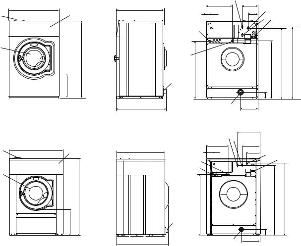
1 |
Electrical connection |
|
|
|
|
|
|
|
|
|
|
|
|
|
|
|||||
2 |
Cold water |
|
|
|
|
|
|
|
|
|
|
|
|
|
|
|
|
|
||
3 |
Hot water |
|
|
|
|
|
|
|
|
|
|
|
|
|
|
|
|
|
||
4 |
Hard water |
|
|
|
|
|
|
|
|
|
|
|
|
|
|
|
|
|
||
5 |
Steam connection |
|
|
|
|
|
|
|
|
|
|
|
|
|
|
|||||
6 |
Drain |
|
|
|
|
|
|
|
|
|
|
|
|
|
|
|
|
|
||
7 |
Liquid detergent supply |
|
|
|
|
|
|
|
|
|
|
|
|
|
|
|||||
8 |
Control panel |
|
|
|
|
|
|
|
|
|
|
|
|
|
|
|
|
|||
9 |
Soap box |
|
|
|
|
|
|
|
|
|
|
|
|
|
|
|
|
|
||
10 |
Door opening, W465H, W475H: ø 310, W4105H: ø 365, W4130H: ø 395, W4180H, W4240H, W4300H: ø 435 |
|||||||||||||||||||
|
|
|
|
|
|
|
|
|
|
|
|
|
|
|
|
|
|
|
|
|
|
|
|
|
|
|
|
|
|
|
|
|
|
|
|
|
|
|
|
|
|
|
|
A |
B |
C |
|
D |
E |
F |
G |
H |
I |
K |
L |
M |
N |
O |
P |
R |
S |
|
|
|
|
|
|
|
|
|
|
|
|
|
|
|
|
|
|
|
|
|
|
W465H |
720 |
|
690 |
1115 |
|
355 |
720 |
825 |
45 |
1030 |
220 |
1010 |
135 |
910 |
830 |
360 |
100 |
240 |
– |
|
|
|
|
|
|
|
|
|
|
|
|
|
|
|
|
|
|
|
|
|
|
W475H |
720 |
|
690 |
1115 |
|
355 |
720 |
825 |
45 |
1030 |
220 |
1010 |
135 |
910 |
830 |
360 |
100 |
240 |
– |
|
|
|
|
|
|
|
|
|
|
|
|
|
|
|
|
|
|
|
|
|
|
W4105H |
830 |
|
705 |
1200 |
|
365 |
740 |
910 |
45 |
1115 |
220 |
1095 |
135 |
995 |
910 |
415 |
100 |
295 |
– |
|
|
|
|
|
|
|
|
|
|
|
|
|
|
|
|
|
|
|
|
|
|
W4130H |
910 |
|
785 |
1325 |
|
435 |
825 |
1035 |
125 |
1245 |
215 |
1225 |
300 |
1125 |
– |
– |
100 |
305 |
455 |
|
|
|
|
|
|
|
|
|
|
|
|
|
|
|
|
|
|
|
|
|
|
W4180H |
970 |
|
870 |
1410 |
|
470 |
910 |
1120 |
115 |
1330 |
230 |
1290 |
315 |
1205 |
370 |
410 |
100 |
335 |
485 |
|
|
|
|
|
|
|
|
|
|
|
|
|
|
|
|
|
|
|
|
|
|
W4240H |
1020 |
|
915 |
1445 |
|
500 |
955 |
1155 |
100 |
1360 |
215 |
1320 |
300 |
1240 |
350 |
360 |
100 |
360 |
510 |
|
|
|
|
|
|
|
|
|
|
|
|
|
|
|
|
|
|
|
|
||
W4300H |
1020 |
1060 |
1445 |
|
500 |
1135 |
1155 |
100 |
1360 |
215 |
1320 |
300 |
380 |
– |
– |
100 |
360 |
330 |
||
|
|
|
|
|
|
|
|
|
|
|
|
|
|
|
|
|
|
|
|
|
W465H, W475H, W4105H, W4130H |
||
|
A |
|
9 |
|
8 |
10 |
|
|
|
|
C |
|
|
D |
|
|
5281 B |
|
Front |
|
W4180H, W4240H, W4300H |
|
|
9 |
A |
|
|
8 |
|
|
|
|
10 |
|
|
|
|
C |
|
|
D |
|
|
5377 A |
|
Front |
|
|
|
3 |
|
|
B |
O |
I |
|
|
G |
L |
2 |
|
|
|
|
|||
|
|
|
||
|
|
|
4 |
7 |
|
1 |
|
|
|
|
5 |
|
|
K |
|
|
|
|
|
|
F |
|
|
M |
|
|
|
N |
|
|
6 |
|
|
|
|
5282 B |
|
P |
|
E |
6 |
R |
|
5283 B |
|
|
Right side |
Rear side |
|
|
|
|
M |
|
|
|
|
2 |
2 |
|
|
|
|
|
|
|
|
|
|
|
S |
|
|
L |
|
|
B |
G |
|
|
|
I |
|
|
|
|
|
|
3 |
|
|
5 |
|
|
|
|
7 |
|
|
|
|
|
|
|
|
1 |
|
|
|
|
|
|
|
|
|
|
K |
H |
|
F |
|
|
|
|
|
|
|
|
|
|
|
|
|
6 |
|
|
|
|
|
|
5379 A |
|
|
|
P |
|
|
|
|
6 |
R |
|
5378 A |
E |
|
|
|
|
||
|
|
|
|
|
||
|
|
|
|
|
|
Right side |
Rear side |
10 |
|
|
|
|
|
|
|
Technical data |
|
|
|
|
|
|
||||
|
|
|
|
|
|
|
|
|
|
|
|
|
|
|
|
|
|
|
|
|
|
|
|
|
|
|
|
|
|
|
|
|
|
|
|
|
|
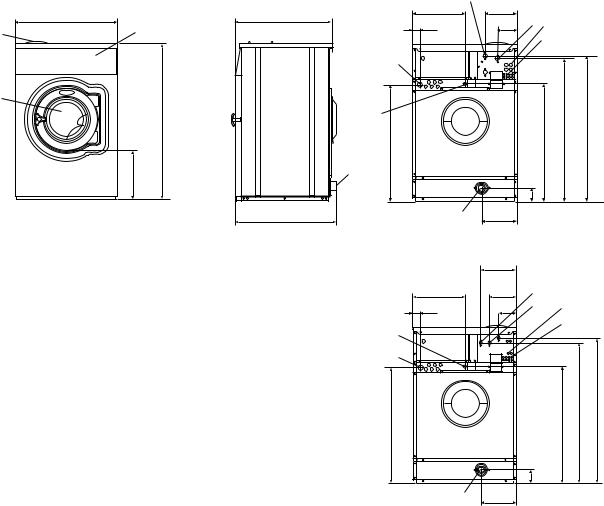
1 |
Electrical connection |
|
|
|
|
|
|
|
|
|
|
|
|
|
||||
2 |
Cold water |
|
|
|
|
|
|
|
|
|
|
|
|
|
|
|
||
3 |
Hot water |
|
|
|
|
|
|
|
|
|
|
|
|
|
|
|
||
4 |
Steam connection |
|
|
|
|
|
|
|
|
|
|
|
|
|
|
|||
5 |
Drain |
|
|
|
|
|
|
|
|
|
|
|
|
|
|
|
|
|
6 |
Liquid detergent supply |
|
|
|
|
|
|
|
|
|
|
|
|
|
||||
7 |
Control panel |
|
|
|
|
|
|
|
|
|
|
|
|
|
|
|||
8 |
Soap box |
|
|
|
|
|
|
|
|
|
|
|
|
|
|
|
||
9 |
Water reuse |
|
|
|
|
|
|
|
|
|
|
|
|
|
|
|
||
10 |
Door opening, W475N/S, W485N/S: ø310, W4105N/S, W4130N/S: ø365, W4180N/S: ø395, |
|
|
|
||||||||||||||
|
W4250N/S, W4330N/S: ø435 |
|
|
|
|
|
|
|
|
|
|
|
|
|||||
|
|
|
|
|
|
|
|
|
|
|
|
|
|
|
|
|
|
|
|
|
|
A |
B |
C |
D |
E |
F |
G |
H |
I |
K |
L |
M |
N |
O |
P |
R |
|
|
|
|
|
|
|
|
|
|
|
|
|
|
|
|
|
|
|
W475N/S |
|
660 |
690 |
1115 |
355 |
725 |
825 |
45 |
1030 |
215 |
1010 |
130 |
830 |
385 |
- |
100 |
225 |
|
|
|
|
|
|
|
|
|
|
|
|
|
|
|
|
|
|
|
|
W485N/S |
|
660 |
730 |
1115 |
355 |
765 |
825 |
45 |
1030 |
215 |
1010 |
130 |
830 |
385 |
- |
100 |
225 |
|
|
|
|
|
|
|
|
|
|
|
|
|
|
|
|
|
|
|
|
W4105N/S |
|
720 |
705 |
1200 |
365 |
740 |
910 |
45 |
1115 |
215 |
1095 |
130 |
910 |
420 |
- |
100 |
235 |
|
|
|
|
|
|
|
|
|
|
|
|
|
|
|
|
|
|
|
|
W4130N/S |
|
720 |
790 |
1200 |
365 |
825 |
910 |
45 |
1115 |
215 |
1095 |
130 |
910 |
420 |
- |
100 |
235 |
|
|
|
|
|
|
|
|
|
|
|
|
|
|
|
|
|
|
|
|
W4180N/S |
|
750 |
880 |
1333 |
435 |
915 |
1035 |
45 |
1245 |
130 |
1225 |
210 |
1040 |
325 |
295 |
100 |
225 |
|
|
|
|
|
|
|
|
|
|
|
|
|
|
|
|
|
|
|
|
W4250N/S |
|
830 |
955 |
1410 |
470 |
990 |
1120 |
45 |
1330 |
160 |
1290 |
245 |
1125 |
325 |
325 |
100 |
265 |
|
|
|
|
|
|
|
|
|
|
|
|
|
|
|
|
|
|
|
|
W4330N/S |
|
910 |
1040 |
1445 |
500 |
1075 |
1155 |
45 |
1365 |
160 |
1325 |
245 |
1155 |
280 |
325 |
100 |
210 |
|
|
|
|
|
|
|
|
|
|
|
|
|
|
|
|
|
|
|
|
|
|
|
|
3 |
|
|
|
|
A |
B |
|
N |
I |
|
|
|
|
G |
L |
2 |
9 |
||
8 |
7 |
|
|
||||
|
|
|
|
|
6 |
||
|
|
|
|
|
|
|
|
|
|
|
|
1 |
|
|
|
10 |
|
|
|
|
|
|
|
|
C |
|
|
4 |
|
|
H |
|
|
|
|
|
|
|
|
|
|
|
|
|
|
|
K |
|
|
|
|
F |
|
|
M |
|
D |
|
5 |
|
|
|
|
|
|
5281 |
|
|
|
P |
|
|
|
E |
|
5 |
R |
|
5283 |
|
|
5282 |
|
|
|||
|
|
|
|
|
|
|
|
|
Front |
Right side |
|
Rear side |
|
W475N/S-W4130N/S |
|
|
|
|
|
|
O |
|
|
|
|
|
|
N |
L |
3 |
|
|
|
|
|
G |
I |
2 |
9 |
|
|
|
|
|
|
|
6 |
|
|
|
|
4 |
|
|
|
|
|
|
|
1 |
|
|
|
H
K
F |
M |
|
P
5459
5 R
Rear side W4180N/S-W4330N/S
|
|
|
|
Technical data |
|
|
|
|
11 |
|||||
|
|
|
|
|
|
|
|
|
|
|
|
|
|
|
|
|
|
|
|
|
|
|
|
|
|
|
|
|
|
|
|
|
W465H |
W475H |
|
W4105H |
|
W4130H |
|
W4180H |
|
W4240H |
|
W4300H |
|
|
|
|
|
|
|
|
|
|
|
|
|
|
|
|
Frequency of the |
|
|
|
|
|
|
|
|
|
|
|
|
|
|
dynamic force |
|
|
|
|
|
|
|
|
|
|
|
|
|
|
Hz |
|
18.3 |
18.3 |
17.1 |
16.3 |
|
15.5 |
|
14.8 |
|
13.7 |
||
|
|
|
|
|
|
|
|
|
|
|
|
|
|
|
|
Floor load at |
|
|
|
|
|
|
|
|
|
|
|
|
|
|
max extraction |
|
|
|
|
|
|
|
|
|
|
|
|
|
|
kN |
|
1.8 ± 0.5 |
1.9 ± 0.5 |
2.5 ± 0.5 |
3.1 ± 0.5 |
|
4.2 ± 1.0 |
|
5.2 ± 1.0 |
|
6.2 ± 1.3 |
||
|
|
|
|
|
|
|
|
|
|
|
|
|
|
|
|
|
|
|
|
|
|
|
|
|
|
|
|||
|
|
|
W475N/S |
W485N/S |
|
W4105N/S |
|
W4130N/S |
W4180N/S |
W4250N/S |
W4330N/S |
|||
|
|
|
|
|
|
|
|
|
|
|
|
|
|
|
|
Frequency of the |
|
|
|
|
|
|
|
|
|
|
|
|
|
|
dynamic force |
|
|
|
|
|
|
|
|
|
|
|
|
|
|
Hz |
9.8/13.8 |
9.3/13.8 |
|
9.1/12.9 |
|
9.1/12.9 |
|
8.8/12.4 |
|
8.3/11.7 |
|
7.9/11.2 |
|
|
|
|
|
|
|
|
|
|
|
|
|
|
|
|
|
Floor load at |
|
|
|
|
|
|
|
|
|
|
|
|
|
|
max extraction |
1.6 ± 1.9/ |
1.7 ± 3.1/ |
|
1.9 ± 2.5/ |
|
2.4 ± 3.1/ |
|
2.9 ± 3.9/ |
3.8 ± 4.9/ |
|
4.6 ± 5.6/ |
||
|
kN |
1.6 ± 2.4 |
1.7 ± 2.6 |
|
1.9 ± 3.0 |
|
2.3 ± 3.8 |
|
3.0 ± 4.8 |
|
3.8 ± 5.9 |
|
4.3 ± 6.9 |
|
|
|
|
|
|
|
|
|
|
|
|
|
|
|
|
Machine presentation |
13 |
|
|
Machine presentation |
1 |
Description |
|
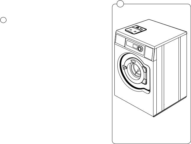
1The machines covered in this service manual include the following models:
Drum volume |
Model name |
(litres) |
|
|
|
65 |
W465H |
75 |
W475H/S/N |
85 |
W485S/N |
105 |
W4105H/S/N |
130 |
W4130H/S/N |
180 |
W4180H/S/N |
240 |
W4240H |
250 |
W4250S/N |
300 |
W4300H |
330 |
W4330S/N |
The machines feature an electronic programme |
|
unit with fixed washing programmes that may be |
|
changed using optional accessories. The pro- |
|
gramme unit also has an in-built self-diagnosis |
|
programme, which increases the possibilities for |
|
quick troubleshooting. |
6569 |
The motor is frequency-controlled and is controlled by an advanced motor control. This allows precise and flexible control of the motor rpm for any application.
The machines are supplied to customer specifications with e.g. electric or steam heating or no heating, and may be connected to various combinations of cold, warm and hard water.

14 |
Machine presentation |
|
|
Function
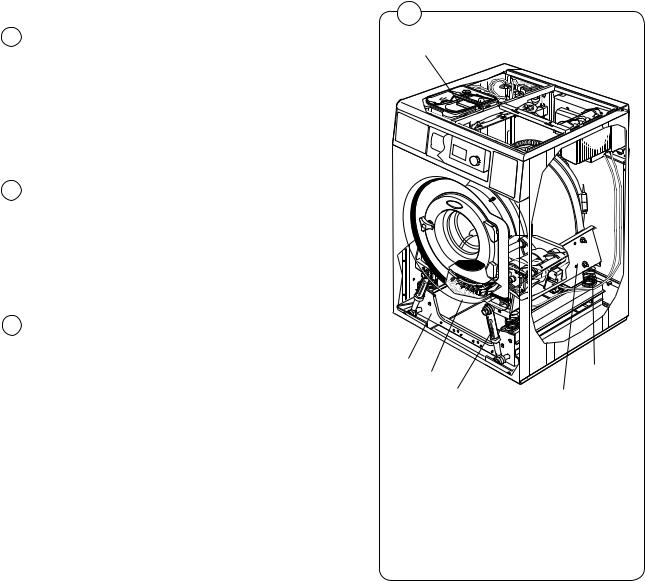
2This section presents a general overview of the functions of the machine. Most functions are then presented in detailed in separate chapters later on in this service manual.
The machine is freely suspended, which means the outer drum and motor are mounted on a supporting ”cradle” that rests on four shock absorbers for dampening the imbalance in the machine.
The washer drum (inner drum) is belt driven by a motor. This motor is located at the bottom of the machine and is mounted on the cradle with a belt tensioner. The inner drum is mounted to the outer drum at the rear plate with two bearings sealed against leakage with sealing rings.
The drain valve is a water-controlled diaphragm valve alternatively, an electrical drain valve or drain pump.
The door is of sturdy type that is interlocked with a lock module when in operation.
The control panel contains a program knob for selecting the fixed wash programs and a display.
The program unit is mounted inside the control panel. Contactor, water valves, etc., are located at the back of the machine.

Machine presentation |
15 |
|
|
2
1 |
2 |
3 |
|
|
|
|
|
4 |
|
|
5 |
18 |
|
|
17 |
|
|
16 |
|
6 |
15 |
|
|
|
|
7 |
14
13
8
12
|
|
|
9 |
|
11 |
10 |
|
1. |
Detergent drawer |
|
10. Shock absorber (not S- and N-model) |
2. |
Water inlet valves |
|
11. Drain valve |
3, |
Power supply |
|
12. Support |
4. |
I/O-board |
|
13. Door |
5. |
Rear electrical module |
|
14. Door lock |
6. |
Motor control |
|
15. Program knob |
7. |
Outer drum |
|
16. Display |
8. |
Coil spring (not S- and N-model) |
17. Control panel |
|
9. |
Motor |
|
18. Program unit |
H - model shown |
6562 |
|
16 |
Machine presentation |
|
|
Program unit
3The control panel contains a program knob and a display. The panel can also be equipped with two preset buttons.
The control panel and display are used by:
•the user to select the machine’s fixed wash programs, to select up to two options for each wash program and for information on the wash process and any fault indicators.
•service personnel for navigation and control of the program unit’s service program.
•programming personnel for setting and program adjustment in the program unit’s software.
4If present, the preset buttons are used for direct start of two preset wash programs.
Using information on torque values from the motor, the weight of each wash is measured before each wash program in order to adapt the amount of water used for washing.
The program unit controls the water valves, drain valve and heating via an I/O board in the rear electrical module. Control signals to external units, such as detergent pumps or external water valves can also be engaged here.
3
Program unit
6581
4
1
2
3 |
4 |
5 |
|
||
K21 |
|
|
|
|
5190 |
6
1.Program unit A1
2.I/O-board A11,
Outputs for water, detergent and drain.
3.Heater element
4Water valves
5.Drain valve
6.Power supply
|
Machine presentation |
17 |
|
Motor and motor control |
5 |
1 |
|
|
|
||
|
The washer drum (inner drum) is belt driven by a |
|
|
5 |
|
|
|
frequency controlled motor. The motor is located |
|
|
|
|
|
|
|
|
on a motor shelf under the outer drum and has |
|
|
|
been arranged with a belt tensioner. |
|
|
6 |
Motor control is microprocessor controlled and |
|
|
can control the acceleration of the drum, its rpm |
|
|
|
|
|
|
|
|
and its retardation very precisely. |
|
|
Motor control communicates with the program unit through a serial interface.
The motor control is voltage-fed over a cable which includes two fuses.
The machine’s motor and motor control are described in more detail in the section Motor.
1. |
Motor control |
2 |
2. |
Motor |
|
H - model shown
6211
6
1
3
2 |
M1 |
5189
1.Program unit A1
2.Power supply
3.Motor control U1
18 |
Machine presentation |
|
|
Door lock
7The door lock is electromechanical with twin safety breakers. The lock is bi-stable, i.e. the lock must be given an active signal from the program unit to lock as well as unlock the door.
8A separate circuit integrated in the program unit checks and controls the locking and unlocking of the door through a lock module. The circuit has separate controls that the drum is empty and that it is stationary. Through sensors in the lock module, the circuit checks the door’s closed and locked position. Together with other controls the program unit conducts, this will guarantee the door cannot be opened by mistake.
The machine’s door and door lock are described in more detail in the section Door and door lock.
7
1
2
1. Program unit
2. Lock module
6568
8
1
2 |
3 |
4 |
5 6
7
M1 |
6658 |
1.Program unit A1
2.Temperature sensor B1
3.Level switch B2
4.Level switch B4
5.Motor control U1
6.Lock module A111
7.Rotation sensor B3
Machine presentation |
19 |
|
|
Heating
9Electric heating heats the washing water with three elements accessible from the front of the machine.
The machine’s heating system is described more thoroughly in the section Heating.
Water connections
9The machine can have one, two, three or four water inlet valves depending on the machine size and customer requirements.
In this unit there are also eight connections for an external detergent feeder.
Rear electric module
10Contains the main switch or terminal block for incoming power, heating contactor, I/O board with outputs for controlling the machine’s water and drain valves and heating. Some machines have an additional I/O board with terminal blocks for connecting e.g. external detergent feeder.
9
1
2
1.Water connections
2.Heating element
6562
10
L1 |
L2 |
L3 |
N |
|
T1 |
T2 |
T3 |
N |
2 (alt.) |
6271
2 (alt.) |
4 |
3 |
1. Rear electric module |
6281 |
2.Power supply connection
3.Distribution board, I/O board 2
4.Contactor K21 (Heat)
20 |
Machine presentation |
|
|
Detergent compartment
11The detergent compartment has four compartments for prewash, main wash, rinse and bleaching agent/liquid detergent.
The machine’s detergent compartment is described more thoroughly in the section Detergent compartment.
Drain valve
11The valve is a diaphragm valve that is opened and closed through water pressure. The control valve is mounted by the water valves.
The machine’s drain valve is described more thoroughly in the section Drain valve.
Frame and suspension
11The machines are freely suspended, i.e. the drum package can move and is suspended in relation to the frame. In this way, a minimum of vibration passes to the bottom plate, which in turn simplifies installation as a concrete foundation is not required.
The machine has four shock absorbers between the bottom plate and the drum package.
The machine’s frame is described more thoroughly in the section Frame.
11
1
2 |
6 |
|
4 |
||
|
||
3 |
5 |
6582
1.Detergent compartment
2.Outer Support
3.Shock absorbers
4.Drain valve
5.Inner support
6.Coil spring
Program unit |
21 |
|
|
Program unit |
1 |
Description
1 |
The program unit is electronic and comprises a |
|
|
|
|
|
|
|
|
|
|
|
|
|
|
|
|
|
|
|
|
|
|
|
|
|
|
|
|
|
|
|
|
|
|
|
|
||
|
|
|
|
|
|
|
|
|
|
|
|
|
|
|
|
|
|
||
|
|
|
|
|
|
|
|
|
|
|
|
|
|
|
|
|
|
||
|
|
|
|
|
|
|
|
|
|
|
|
|
|
|
|
|
|
||
|
|
|
|
|
|
|
|
|
|
|
|
|
|
|
|
|
|
||
|
|
|
|
|
|
|
|
|
|
|
|
|
|
|
|
|
|
||
|
circuit board containing microprocessor, pro- |
|
|
|
|
|
|
|
|
|
|
|
|
|
|
|
|
|
|
|
gram memory, current regulating circuits, tem- |
|
|
|
|
|
|
|
|
|
|
|
|
|
|
|
|
|
|
|
|
|
|
|
|
|
|
|
|
|
|
|
|
|
|
|
|
|
|
|
|
|
|
|
|
|
|
|
|
|
|
|
|
|
|
|
|
|
|
|
|
|
|
|
|
|
|
|
|
|
|
|
|
|
|
|
|
|
|
|
perature and level control, etc. |
|
|
|
|
|
|
|
|
|
|
|
|
|
|
|
|
|
|
2The program unit receives its power from a separate voltage unit.
The program unit receives information from the temperature sensor, door lock and level switches. There is also a serial interface to the motor control.
The program unit controls the water and drain valves and the heating via the I/O board, door closing/opening via a drum module and the motor via the motor control.
6211 6207
2
|
|
|
1 |
|
|
|
5 |
|
|
|
2 |
3 |
4 |
E1-E3 |
7 |
9 |
10 |
|
11 |
|
6 |
M1 |
|
|
|
|
|
|
|
|
|
12 |
13 |
|
|
8 |
|
|
|
||
|
|
|
|
|
|
|
K21 |
|
|
|
|
|
|
14 |
1. |
Program unit A1 |
8. |
Rotation sensor B3 |
2. |
Temperature sensor B1 |
9. |
Door lock module A41 |
|
|
3, |
Level switch B2 |
10. |
Voltage unit A5, PSU |
|
4, |
Level switch B4 |
11. |
I/O board |
|
5. |
Display A2 |
12. |
Watervalves |
|
6. |
Heater element E1 -3 |
13. |
Drain valve |
|
7. |
Motor control U1 |
14. |
Power supply |
22 |
|
|
Program unit |
|
|
|
|
Inputs and outputs |
|
||
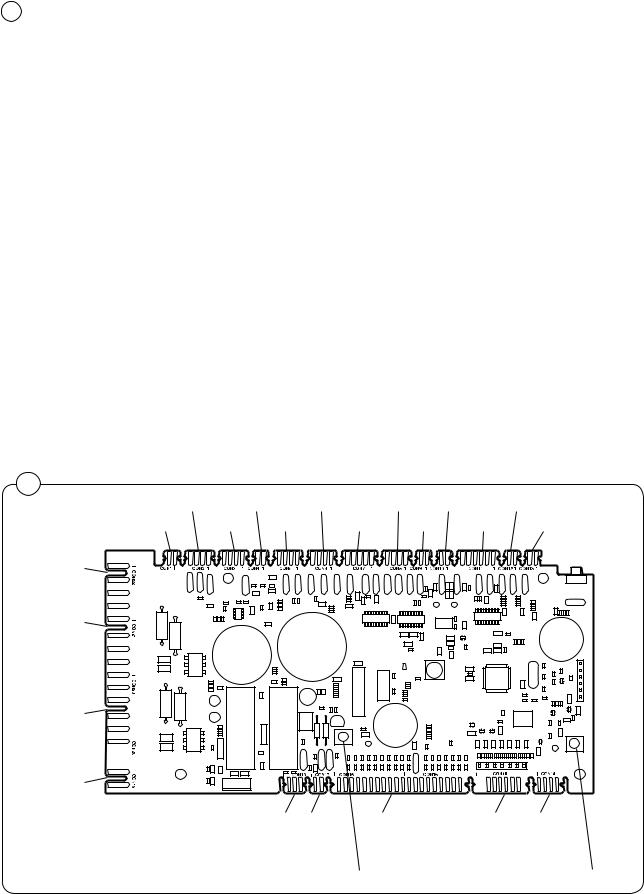
3 |
|
The program unit board has the following inputs and outputs: |
|
|
|
|
|
|
|
Board connector |
Function |
|
|
|
|
|
|
Con 1 |
Input from temperature sensor (Temp) |
|
|
Con 2 |
Databus (D-bus) |
|
|
Con 3 |
Databus (D-bus) |
|
|
Con 4 |
Tacho |
|
|
Con 5 |
Communication, motor control unit (M-com) |
|
|
Con 6 |
Connection for software/service download (P-load) |
|
|
Con 7 |
Input, Level sensors (level) |
|
|
Con 8 |
Serial communication (RS 232) |
|
|
Con 9 |
Input, Emergency stop (EMERG) |
|
|
Con 10 |
Input, Free wash (key switch) (FREE W) |
|
|
Con 11 |
Input, Coin meter (coin) |
|
Con 12 |
Input, function depending on model (INPUT) |
|
|
Con 13 |
Service button in rear electrical module (SERV) |
|
|
Con 14 |
Control knob, pulses |
|
|
Con 15 |
Control knob, switch |
|
|
Con 16 |
Display |
|
|
Con 17 |
Input, Buzzer |
|
|
Con 18 |
Counter input |
|
|
Con 19 |
Door, out (DO) |
|
|
Con 20 |
Door, in (DOOR IO) |
|
|
|
Con 21 |
Mains voltage bus (PBUS) |
|
|
Con 22 |
Mains voltage bus (PBUS) |
|
|
|
|
3
Con 2 Con 4 Con 6 |
Con 8 Con 10 Con 12 |
|
Con 1 Con 3 Con 5 |
Con 7 Con 9 Con 11 Con 13 |
|
Con 22
Con 21
Con 20
Con 19
|
|
Con 18 Con 17 Con 16 |
Con 15 Con 14 |
1. |
CPU reset |
|
|
2. |
DLCU reset |
2 |
1 |
|
|

Program unit |
23 |
|
|
Menu tree
The machine software is constructed with menus that are structured according to the menu tree below. The menus become available when the machine is in service mode, see under the heading ”Engaging service mode”.
|
|
|
|
|
|
|
|
|
|
|
SERVICE |
|
|
|
|
|
|
|
|
|
|
|
|
|
|
|
|
|
|
|
|
|
|
|
|
|
|
|
ACTIVATE OUTPUTS |
|
|
|
|
|
|
|
|
|
|
|
|
|
SHOW INPUTS |
|
|
|
|
|
|
|
|
|
|
|
|
|
ARTICLE NUMBER |
|
|
|
|
|
|
|
|
|
|
|
|
|
SHOW DLCU COM. |
|
|
|
|
|
|
|
|
|
|
|
|
|
RESET DLCU |
|
|
|
|
|
|
|
|
|
|
|
|
|
SHOW MCU COM. |
|
|
|
|
|
|
|
|
|
|
|
|
|
RESET MCU |
|
|
|
|
|
|
|
|
|
|
|
|
|
SHOW SINGLE |
|
|
|
|
|
|
|
|
|
|
|
|
|
SHOW COM.PORTS |
|
|
|
|
|
|
|
|
|
|
|
|
|
WEIGHT CALIBRATION |
|
|
|
|
|
|
|
|
|
|
|
|
|
MEASURE WEIGHT |
|
|
|
|
|
|
|
|
|
|
|
|
|
MEASURE UNBALANCE |
|
|
|
|
|
|
|
|
|
|
|
|
|
DISPLAY TEST |
|
|
|
|
|
|
|
|
|
|
|
|
|
CLEAR SERVICE TIMER |
|
|
|
|
|
|
|
|
|
|
|
|
|
EXIT |
|
|
|
|
|
|
|
|
|
|
|
See programming manual |
|
|||
|
|
|
|
|
|
|
|
|
|||||
MAIN MENU |
|
|
|
|
|
|
|
See programming manual |
|
||||
|
|
|
|
|
|
|
|
||||||
|
|
|
|
|
|
|
|
|
|
|
|
|
|
SERVICE |
|
|
|
|
|
|
|
|
|
|
|
|
|
PARAMETER PROG. |
|
|
|
|
|
|
|
|
|
|
|
|
|
STATISTICS |
|
|
|
|
|
|
|
|
|
|
|
|
|
CONFIG 1 |
|
|
|
|
|
|
|
|
|
|
|
|
|
CONFIG 2 |
|
|
|
|
|
|
|
|
Not used |
|
|||
ADJUST DISPLAY |
|
|
|
|
|
|
|
|
See programming manual |
|
|||
|
|
|
|
|
|
|
|
|
|||||
RESET TO FACTORY |
|
|
|
|
|
|
|
|
See programming manual |
|
|||
|
|
|
|
|
|
|
|
|
|||||
ACTIVATE WASH PROGR. |
|
|
|
|
|
|
|
|
|
|
|
|
|
CONFIG BUTTONS |
|
|
|
|
|
|
|
|
|
|
ACTIVATE WASH PROGR. |
|
|
|
|
|
|
|
|
|
|
|
|
|
|||
I/O ADDRESS |
|
|
|
|
|
|
|
|
|
|
|
|
|
PRICE PROGRAMMING |
|
|
|
|
|
|
|
|
|
G01 NORMAL 40 |
|
||
|
|
|
|
|
|
|
|
|
G01 NORMAL 60 |
|
|||
|
|
|
|
|
|
|
|
|
|
|
G01 NORMAL 95 |
|
|
|
|
|
|
|
|
|
|
|
|
|
G01 SYNTHETIC 40 |
|
|
|
|
|
|
|
|
|
|
|
|
|
|
||
|
|
|
|
|
|
|
|
|
|
|
G01 DELICATE 30 |
|
|
|
|
|
|
|
|
|
|
|
|
|
G01 HANDWASH |
|
|
|
|
|
|
|
|
|
|
|
See programming manual |
|
|||
|
|
|
|
|
|
|
|
|
|
||||
|
|
ADDRESS I/O BOARD |
|
|
|
ADDRESS I/O BOARD |
|
I/O BOARD 1 |
|
||
REMOVE I/O BOARD |
|
I/O BOARD 2 |
|
I/O BOARD 3 |
|
|
|
I/O BOARD 4 |
|
|
I/O BOARD 5 |
|
|
I/O BOARD 6 |
|
|
I/O BOARD 7 |
|
|
I/O BOARD 8 |
|
|
I/O BOARD 9 |
|
|
I/O BOARD 10 |
CONFIG 1
PAUSE PERMITTED
RAPID ADVANCE
REGRET TIME
NEW PROG. SELECT
SHOW TIME
SHOW TEMP
SHOW IS LEVEL
MACHINE HEATED
HEATING RELAY ON
TEMP CONTROL WATER SHOW °C
DELAYED START
AUTO RESTART
AUTO START PAID
SHOW COIN COUNTER
SHOW HOUR COUNTER
SHOW PROG. COUNTER BUTTON CLICK FLASH LIGHT ON HEAT ERROR ON SHOW MODULE NUMBER AUTO PROG SELECT MEASURE WEIGHT POWER CTRL HEAT POWER CTRL EXTRACT BLOCK START ACTIVE FIRST LANGUAGE SECOND LANGUAGE
SEC. LANGUAGE ACTIVE COIN VALUE 1
COIN VALUE 2
DECIMAL IN PRICE
TIMEOUT, DISPLAY, SEC TIMEOUT,END BUZZ. SEC TIMEOUT,PAUSE BUZZ. SEC MAX FILL TIME, SEC
6. WATER IN DRUM
7. DRUM OVERFILLED
10. DRUM NOT DRAINED MACHINE ADDRESS PASSWORD
SHOW WEIGHT TIME, SEC MAXDIFF.WASH TIME MIN DEFAULT HEAT
BACK LIGHT TIME SEC. OFFS.LEVEL READING MM DISPLAY WARNING, SEC FLUSH DELAY, LIQ. SEC FLUSH ON, LIQ. SEC FLUSH DELAY, POWD.SEC FLUSH ON, POWD.SEC LEVEL COOL DOWN, SCU COOL STEP TEMP
COOL MIDDLE TEMP DISPLAY STATIST.SEC SHOW.STAT.DOUBLECLI. LAST PROG. TIMEOUT DRY COM. PORT CPU DRY COM. PORT I/O QUICK START BUTTON 1 QUICK START BUTTON 2 VOLUME
VGB WELC. TIMEOUT SEC. VGB MESS. ANTICR. SEC. SERVICE INTERVAL HOUR
24 |
Program unit |
|
|
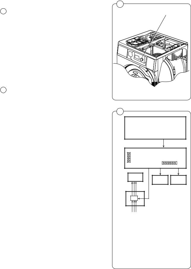
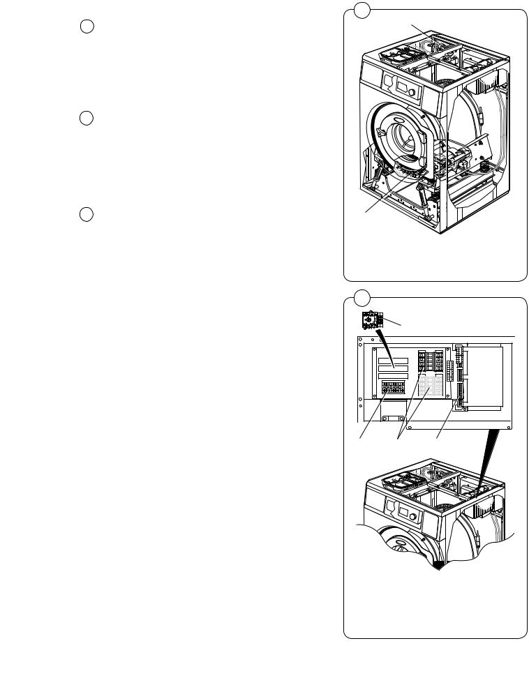
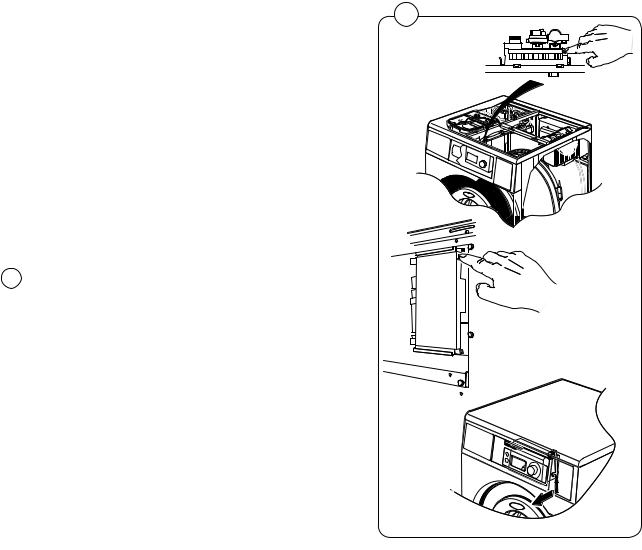
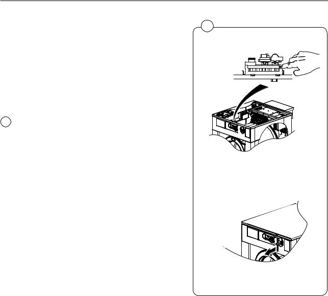
Activating service mode
Service mode is activated by using one of the following alternative:
|
Alt. 1 |
Service switch on the CPU board under |
|
|
the top cover on the front of the machine. |
|
Alt. 2 |
Service switch on the I/O board at the |
|
|
rear of the machine to the right of the |
|
|
electrical connection. |
|
Alt. 3 |
Service switch on the CPU card will be |
|
|
activated via a link arm which can be ac- |
|
|
cessed from the front below the top front |
|
|
panel. (On machines with coin counting |
|
|
only.) |
1 |
Press the service button about 2 sec. |
|
1
Alt. 1
6582
Alt. 2
6580
Alt. 3
6638
Program unit
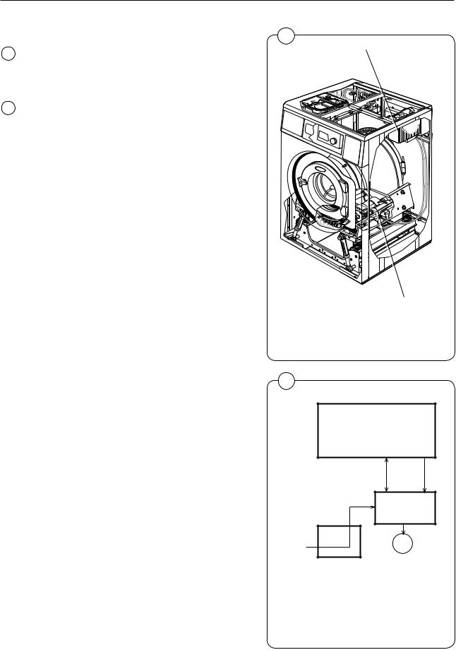
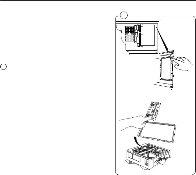
Only for WB4130H, WB4180H |
1 |
|
Service mode is activated by using one of the following alternative:
Alt. 1 Service switch on the I/O board at the rear of the machine to the right of the electrical connection.
Alt. 2 Service switch on CPU card under left |
6578 |
|
|
hand side of the top cover. |
|
1 Press the service button about 2 sec. |
|
25
Alt. 1
6580
Alt. 2
6856
26 |
Program unit |
|
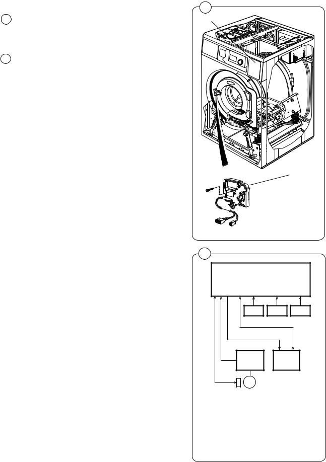
Only for WD4130, WD4240 |
1 |
|
|
|
|
|
Service mode is activated by using one of the |
|
|
following alternative: |
|
|
Alt. 1 Service switch on the CPU board under |
|
|
the top cover on the front of the machine. |
Alt. 1 |
Alt. 2 Service switch on the CPU card will be activated via a link arm which can be accessed from the front below the top front panel.
1 |
Press the service button about 2 sec. |
|
TEMP |
D-BUS |
D-BUS |
TACHO |
M-COM |
P-LOAD |
LEVEL |
RS232 |
EMERG |
FREE |
COIN |
INPUT |
SERV |
6582 A
Alt. 2
6638
Program unit |
27 |
|
|
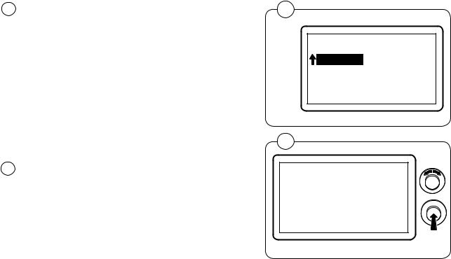
2The machine software will now switch to its service mode. The display lists the submenus available in this mode.
This service manual describes the functions and programming instructions for the following submenus:
•SERVICE
•CONFIG 1
•ACTIVATE WASH PROGR.
•I/O ADDRESS
For submenus not presented in this document, please refer to the programming manual.
3To save changes to the machine’s flash memory, they must be confirmed in a menu that is displayed automatically whenever a change has been made and you are exiting the menu.
2
MAIN MENU 01.00.00.00
SERVICE PARAMETER PROG STATISTICS CONFIG 1 CONFIG 2
6204
3
SAVE TO MEMORY
YES
6204
28 |
Program unit |
|
|
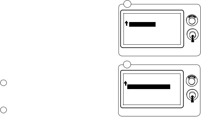
Service program
The service program is used to facilitate troubleshooting the machine. Using this program you can:
•control the machine functions individually
•check the sensor signals to the CPU
•check the communication in the machine control system
•calibrate the weighing function
•weigh and measure unbalance
•check the display
4Engage service mode, mark the SERVICE row in the main menu and press the knob.
The display will now show the different submenus in the service program.
•ACTIVATE OUTPUTS
5• SHOW INPUTS
•ARTICLE NUMBER
•SHOW DLCU COM.
•RESET DLCU
•SHOW mcu COM.
•RESET mcu
•SHOW SINGLE
•SHOW COM.PORTS
•WEIGHT CALIBRATION
•MEASURE WEIGHT
•MEASURE UNBALANCE
•DISPLAY TEST
Select the desired menu and press the knob.
4
MAIN MENU 01.00.00.00
SERVICE
PARAMETER PROGR.
STATISTICS
CONFIG 1
CONFIG 2
ADJUST DISPLAY
6204
5
*SERVICE*
01.01.00.00
ACTIVATE OUTPUTS SHOW INPUTS ARTICLE NUMBER SHOW DLCU COM. RESET DLCU
6204
Program unit
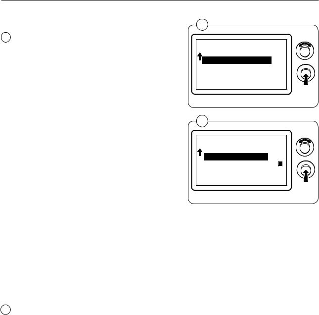
ACTIVATE OUTPUTS
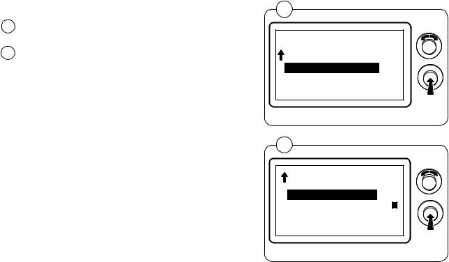
6Select the ACTIVATE OUTPUTS row and press the knob.
The display now shows the functions (outputs) that can be activated.
•DOOR
•NORMAL DRAIN
•DRAIN A-D
•COLD WATER
•HOT WATER
•HARD WATER
•TANK 1-4 WATER
•HEAT 1
•HEAT 2
•HEAT 3
•POWDER DETERGENT
•LIQUID DETERGENT
•INTERLOCK MOTOR
•PROGRAM RUN
•MACHINE FREE
•DRUM CW
•DRUM CCW
•DISTRIBUTION
•LOW EXTRACT
•MEDIUM EXTRACT
•HIGH EXTRACT
•TURBO EXTRACT
•CLUTCH
•START CAP. RELAY
•BUZZER
•FLASH LIGHT
•OIL PULSE
•SLOT BLOCKING
•LCD BACK LIGHT ON
•ALTERNATE DOOR LOCK (AHL/OPL)
•FOAM RELAY
•EXIT
7Select the desired function and press the knob.
Several outputs can be activated simultaneously. An activated output is indicated by a filled box to the right.
6
*SERVICE*
01.01.00.00
ACTIVATE OUTPUTS SHOW INPUTS ARTICLE NUMBER SHOW DLCU COM. RESET DLCU
7
ACTIVATE OUTPUTS 01.01.01.00
DOOR
NORMAL DRAIN
DRAIN A-D
COLD WATER
HOT WATER
29
6204
6204
30 |
Program unit |
|
|
SHOW INPUTS
8Select the SHOW INPUTS row and press the knob. The display now shows the sensor signals
(inputs) that can be activated.
9
•COUNT 1
•DOOR LOCK
•DOOR CLOSED
•START BUTTON CPU
•SERVICE BUTTON
•PRICE PROGRAMMING
•PRICE REDUCTION
•FREE WASH
•COIN 1
•COIN 2
•EMERGENCY STOP
•ALTER. HEAT RELAY
•START/STOP
•TEMPORARILY PAUSE
•BLOCK START BUTTON
•DRUM OVERFILLED
•PC5
•TEMPERATURE PAUSE
•TANK 1 EMPTY
•TANK 2 EMPTY
•TANK 3 EMPTY
•TANK 4 EMPTY
•OIL EMPTY
•TEMPERATURE
•LEVEL A/D SCU
•LEVEL SCU
•LEVEL MM
•TEMPERATURE DISP
•DRUM SPEED RPM
•TACHO SIGNAL
•LIQUID TANK EMPTY
•QUICK START 1
•QUICK START 2
•UNBALANCE
•BUTTON I/O 1
•INTERLOCK I/O 1
•BUTTON I/O 2
•INTERLOCK I/O 2
•BUTTON I/O 3
•INTERLOCK I/O 3
•BUTTON I/O 4
•INTERLOCK I/O 4
•BUTTON I/O 5
•INTERLOCK I/O 5
•BUTTON I/O 6
•INTERLOCK I/O 6
•BUTTON I/O 7
•INTERLOCK I/O 7
•BUTTON I/O 8
•INTERLOCK I/O 8
•BUTTON I/O 9
•INTERLOCK I/O 9
•BUTTON I/O 10
•INTERLOCK I/O 10
•RAPID ADVANCE
•SERVICE 2 INPUT
•EXIT
8
*SERVICE*
01.02.00.00
ACTIVATE OUTPUTS SHOW INPUTS ARTICLE NUMBER SHOW DLCU COM. RESET DLCU
6204
9
SHOW INPUTS 01.02.01.00
COUNT 1
DOOR LOCK
DOOR CLOSED
START BUTTON CPU
SERVICE BUTTON
6204
Several inputs can be shown simultaneously. An activated input is indicated by a filled box to the right or as a value, for example mm.
 Loading...