

Page 1

Vickers
Service Data
®
Piston Pumps
PVH57/63 Variable Displacement
Piston Pump - 11 Design
Revised 11/01/97
M-2206-S
Page 2
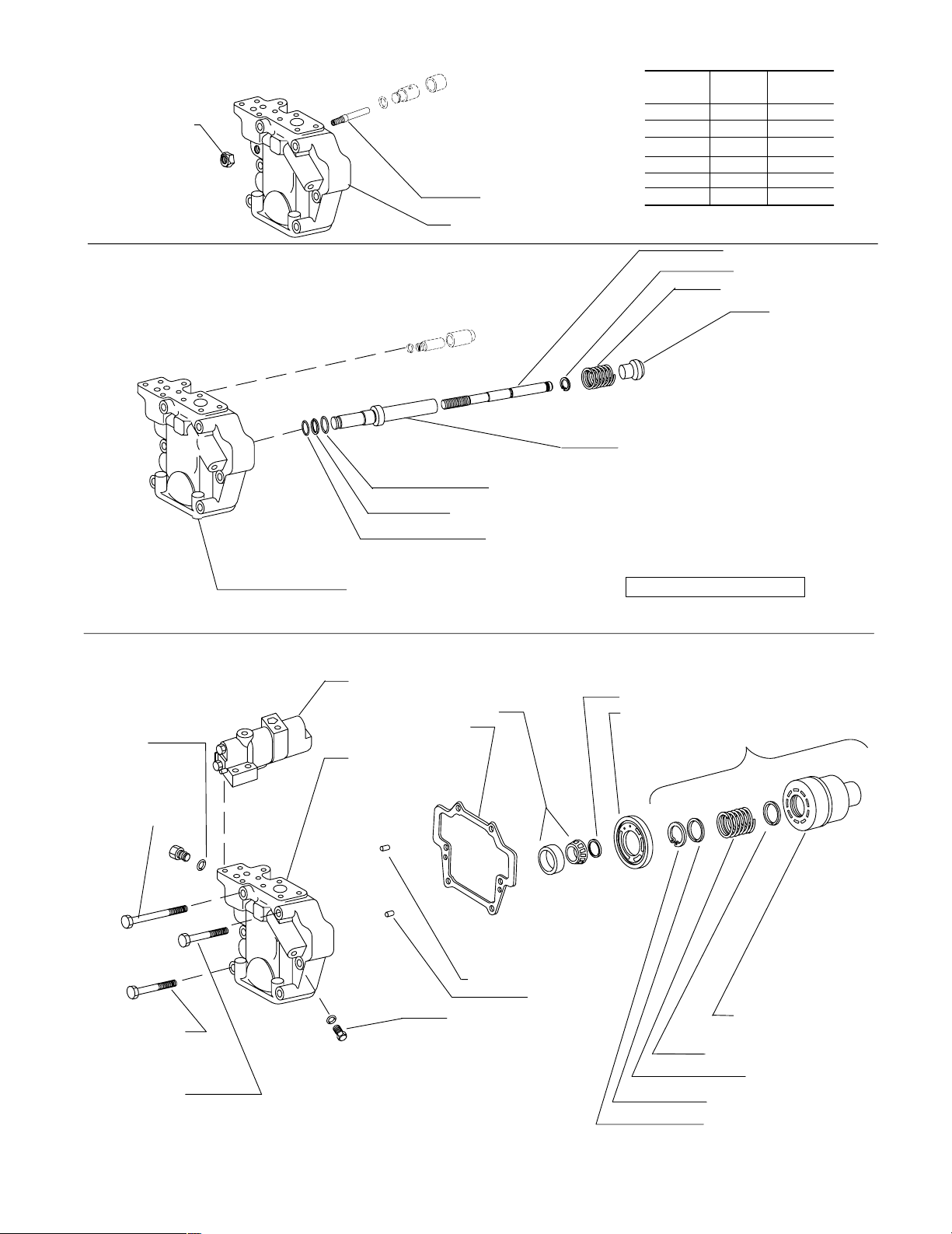
Maximum Adjustable Stop – S Option
913341 Locknut
Torque 25-50 N.m.
(18-37 lb. ft.)
860741 Adj. screw
Valve block (See table)
Valve Block Table
Pump
Type
F–11–C
M–11–C
SF–11–C
SM–11–C
F–11–CT
M–11–CT
RH LH
928631
928632
928618
928619
860846
860847
928679
928680
928667
928668
860855
860856
Torque Limiter – T Option
Standard – C/CM/CMV/CV/IC
396093 O-ring
(2 Req’d)
474753 Screw
Torque 64-78 N.m.
(47-57 lb. ft.)
263069 O-ring
197577 Back-up ring
262339 O-ring
Valve block (See table)
Pump control (see controls pages)
513436 Bearing S/A
513846 Gasket
Valve block
(see table)
928446 Bias piston
928456 Lock ring
526665 Bias spring
928447 Cap
928448 Bias sleeve
Torque 97-106 N.m (71-78 lb. ft)
Grade RC30 compound
Torque control models
926258 Shaft spacer kit
Valve plate (see table)
Rotating group kit (See table)
470866 Screw
(4 Req’d)
Torque 64-78 N.m.
(47-57 lb. ft.)
470871 Screw
Torque 64-78 N.m. (47-57 lb. ft.)
Eaton Hydraulics, Incorporated 2000
All Rights Reserved
471512 Pin (2 Req’d)
248935 Pin
689461 Plug (2 Req’d)
Torque 12.7-13 N.m. (8.9-9.5
lb.ft.)
Cylinder block
(See table)
680624 Spring guide
627524 Spring
584524 Spring guide
85560 Retaining ring
Page 3
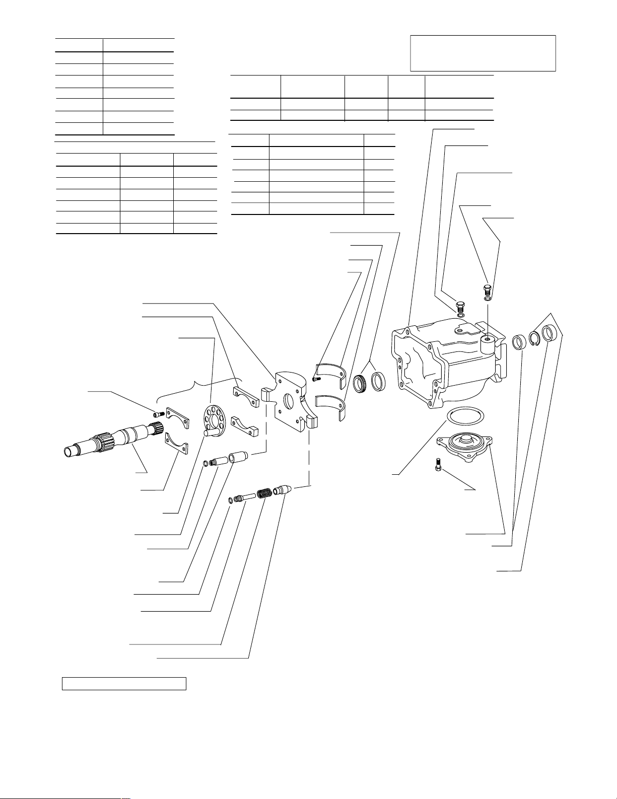
Housing Flange/Seal
526614
864204
883084
864313
860808
860815
864203
Pump Type
57 680630 680631
57QI 514128 514121
57QP 913696 N/A
63 934442 934439
63QI 928579 860774
63QP 934443 N/A
690832 Yoke S/A
690801 Spacer
(2 Req’d)
Shoe cage (See table)
-C-*S
-C-*D
-C2-*S
-C2-*D
-C3-*S
-M-*S
-130 suffix
V alve Plate Table
RH LH
Model
Designation
57 Size
63 Size
Shaft Type Key
527166 1 – Straight keyed 114516
513839 2 – Splined –
883083 N – Straight keyed 472287
864342 1 – Straight key (thru) 114516
526684 2 – Spline (thru) –
913978 8 - Splined (130) –
513433 Bearing S/A
513885 Saddle bearing
513886 Saddle bearing
690339 Screw (2 Req’d)
Torque 3.6-4.4 N.m.
(2.3-3 lb. ft.)
Piston & Shoe
S/A (9 req’d)
02-306362
02-306363
Cylinder
Block
937023
937024
Note
Complete replacement via rotating
group kits is recommended.
Shoe
Cage
584512
860754
Rotating Group
Kit
877420
02-334358
Housing (See table)
396102 O–Ring
Torque 97-106 N.m.
396098 O–Ring
Torque 54-59 N.m.
513602 Plug
(71-78 lb. ft.)
186580 Plug
(40-43 lb. ft.)
Rotating group kit (See table)
473741
Screw
(4 Req’d)
Torque 13-15
N.m. (9-11 lb. ft.)
Shaft (See table)
690218 Limiter
(2 Req’d)
Piston & Shoe S/A
(See table)
262355 O–Ring
690210 Control rod
Torque 82-91 N.m. (60-67 lb. ft.)
Grade RC30 compound
69021 1 Control piston
262355 O–Ring
526685 Bias rod
Torque 82-91 N.m. (60-67 lb. ft.)
Grade RC30 compound
526665 Spring
526668 Bias piston
Non-torque control models
Available in double shaft
seal kit 02–102244
Available in bearing kit 877423
Available in bearing/yoke
kit 02-334832
576601 O–Ring
Available in PVH57 rotating group kit.
Available in PVH63 rotating group kit.
470793 Screw
(3 Req’d)
Torque 7-9 N.m.
(5-6.6 lb. ft.)
526616 Cover
513439 Shaft seal
(2 Req’d if dual seal)
103824 Retaining ring
(2 Req’d if dual seal)
NOTE
Right hand rotation shown. View
is opposite for left hand rotation.
Please refer to Overhaul Manual
M-2210-S.
NOTE
Use shims as required to obtain
0.01–0.10 mm (.0004–.004 in.) axial
shaft end play.
NOTE
For satisfactory service life of these
components in industrial applications,
use full flow filtration to provide fluid
which meets cleanliness code 16/14/12
or cleaner.
Page 4

Load Sensing & Pressure
Compensator Control C(M)*V
857688 Load sense spring
857674 Spring guide
Orifice plug (See table)
181728 Plug Torque 29-32 N.m. (21-24 lb. ft.)
396096 O-Ring
473765 Screw
(4 Req’d) Torque 31-37 N.m. (23-28 lb. ft.)
Body (See table)
857673 Load sense spool
857674 Spring guide
857679 Pin spring stop
396100 O-Ring
860748 Plug
Torque 75-83 N.m.
(55-60 lb. ft.)
860747 Nut
(2 Req’d)
Torque 14-20 N.m.
(10-14 lb. ft.)
860749 Plug
Torque 97-106 N.m.
(71-78 lb. ft.)
396102 O-Ring
860750 Adj. screw (2 Req’d)
857734 Spring guide
Control spring (See table)
627391 Plug
(2 Req’d)
Torque 29-32 N.m.
(21-24 lb. ft.)
396096 O-Ring
(2 Req’d)
857672 Pressure limiter spool
177969 O-Ring (3 Req’d)
Pressure Compensator Control C & CM
Control spring (See table)
857734 Spring guide (2 Req’d)
857722 Body
473765 Screw (4 Req’d)
Torque 31-37 N.m. (23-28 lb. ft)
857672 Spool
396096 O-Ring
857734 Spring guide
Control
Type
Control Kit
02–125161
CV
02–160591
CVB
02–306056
CMV
All parts shown are included in control kit.
Pressures must be set by user to circuit requirements.
Pressure
range
140–280 Bar 857681
35–140 Bar
Spring
857675
857733
928442
857733
396102 O-Ring
860750 Adj. screw
Torque 97-106 N.m.
Body Orifice
Plug
–
433543
–
860749 Plug
(71-78 lb. ft.)
627391 Plug
Torque 29-32 N.m.
(21-24 lb. ft.)
177969 O-Ring (3 Req’d)
860747 Nut
Torque 14-20 N.m.
(10-14 lb. ft.)
Control Type
C
CM
All parts shown are included in control kit.
Pressures must be set by user to circuit requirements.
Control Kit
02–125160
02–125162
Pressure range
140–280 Bar
35–140 Bar
Spring
857681
857675
Page 5

Industrial Control (IC)
473769 Screw (2 Req’d)
Torque 31-37 N.m. (23-28 lb. ft.)
407533 Plug
Torque 12.1-12.4 N.m. (8.9-9.1 lb. ft.)
396093 O-Ring
396092 O-Ring (3 Req’d)
627391 Plug (3 Req’d)
Torque 9.8-10.2 N.m. (7.2-7.5 lb. ft.)
Body (see table)
857688 Spring
857679 Pin spring stop
857674 Spring guide (2 Req’d)
396100 O-Ring
860747 Nut
Torque 14-20 N.m.
(10-14 lb. ft.)
860750 Adj. screw
860748 Plug
Torque 75-83 N.m. (55-60 lb. ft.)
Torque Limiter – T Option
860749 Plug
Torque 75-83 N.m
(102-112 lb. ft.)
860750 Adjusting Screw
860747 Nut
Torque 8-10 N.m
(11-14 lb. ft.)
1649 Ball
471627 Pin
937272 Check valve
Torque 1.7-2.3 N.m
(2.3-3.1 lb. ft.)
217669 O-ring
177969 O-ring
(2 req’d)
Control Kit Threads Body
02–151904 inch 883386
02–151905 metric 860628
All parts shown are included in control
kit. Pressures must be set by user to circuit
requirements.
928388 Guide
Spring (See table)
857734 Guide
263069 O-ring
473765 Screw
(2 Req’d) Torque 31-37 N.m. (23-28 lb. ft.)
113000 Plug
Torque 5.1-5.9 N.m. (3.7-4.4 lb. ft.)
860566 Orifice plug
Torque 1.7-2.3 N.m.
(1.2-1.7 lb. ft.)
396096 O-Ring
181728 Plug
Torque 29-32 N.m.
(21-24 lb. ft.)
627391 Plug
Torque 29-32 N.m.
(21-24 lb. ft.)
396096 O-Ring
939816 Spool
177969 O-Ring
(2 req’d)
216630 O-Ring
NOTE
IC kits pre-set to 20-30 bar differential
pressure with all orifices/plugs in
place. Reference Vickers Overhaul
Manual M-2210-S for proper orifice/
plug configuration in various circuits
prior to control installation.
913453 Guide
473773 Screw (4 req’d)
Torque to 31-37 N.m
(42-50 lb. ft.)
197594 Back-up ring
262356 O-ring
860655 Plug Torque 75-83
N.m (102-112 lb. ft.)
248823 Pin
186580 Plug
Torque 54-59 N.m
(73-80 lb. ft.)
263497 O-ring
113000 Plug
Torque 15-17 N.m
(20-23 lb. ft.)
913454 Spool
860653 Body
177969 O-ring (5 req’d)
577639 Sleeve
262356 O-ring
Model designation Control Kit
T**-31
T**S-31
02–314944
02–335254
Spring
857675
857681
248845 Pin
932716 Retainer Ring
(Screw into bottom of thread)
932716Connector
Torque 54-59 N.m
(73-80 lb. ft.)
263497 O-ring
Torque summation parts
Page 6

*A* Thru–drive
Valve block
(See table)
Thru–drive
Adapter location
(See table)
470866 Screw (2 Req’d)
Torque 64-78 N.m. (47-57 lb. ft.)
‘‘A’’ Thru–drive
474753 Screw (2 Req’d)
Torque 64-78 N.m.
(47-57 lb. ft.)
474756 Screw (2 Req’d, SAE “A” pad)
Torque 64-78 N.m. (47-57 lb. ft.)
473817 Screw (2 Req’d, SAE “B”/“C” pad)
Torque 64-78 N.m. (47-57 lb. ft.)
Coupling
(See table)
Rear
Pump
O-Ring
(See table)
Model designation
LAF–11–C*
LAM–11–C*
RAF–11–C*
RAM–11–C*
LAF–11–CT
LAM–11–CT
RAF–11–CT
RAM–11–CT
‘‘B’’ & ‘‘C’’ Thru–drive Adapter
Model Designation
*–*BF–11–*
*–*BM–11–*
*–*CF–11–*
*–*CM–11–*
Notes:
1.‘‘F’’ type equal SAE threads
2. ‘‘M’’ type equal metric threads
3. ‘‘B’’ and ‘‘C’’ thru-drives created from
‘‘A’’ thru-drive pump with ‘‘B’’ or ‘‘C’’
thru-drive adapter kit installed.
4. All screws/O-rings are included with
each ‘‘kit’’ to convert from ‘‘A’’ to
‘‘B’’ or ‘‘C’’ thru-drive unit.
Valve block
w/ SAE ‘‘A’’ Pad
928705
928706
928730
928731
860837
860838
860828
860829
Adapter
Pad Kit
876390
876394
876389
876392
Adapter
Flange
526670
876393
692934
876391
O-Ring
576601
Coupling
Type
864460
9 tooth
SAE-A
O-Ring CouplingTypes
401525
353264
526694 SAE-B 13 tooth
526695 SAE-BB 15 tooth
526696 SAE-C 14 tooth
SAE–A, 2–Bolt Cover
Plate 939790
(Fits –031 Suffix Pumps)
*AF Units use Screw 170177
(2 req’d)
**AM Units use Screw 470837
(2 req’d)
Page 7

Typical Cross Section
Control Piston
Control Rod
Valve Block
Port #1
Position outer shaft
seal facing shaft end
Position inner shaft
seal facing bearing
Pump Startup
Make sure the reservoir and circuit are
clean and free of dirt and debris prior
to filling with hydraulic fluid.
Fill the reservoir with filtered oil to a
level sufficient to prevent vortexing at
suction connection to pump inlet. It is
good practice to clean the system by
flushing and filtering using an external
slave pump.
Before starting the pump, fill with fluid
through one of the ports. This is particularly important if the pump is above
the fluid level of the reservoir.
Note
Parts are shown as installed for right
hand rotation. For left hand rotation,
install control rod and control piston
in valve block port #2. Install bias
rod, bias piston and spring in valve
block port #2.
When initially starting the pump, remove
all trapped air from the system. This can
be accomplished by loosening the pump
outlet fittings or connections before
starting the pump, or by using an air
bleed valve. All inlet connections must
be tight to prevent air leaks.
Once the pump is started, it should
prime within a few seconds. If the pump
does not prime, check to make sure that
there are no air leaks in the inlet line
and connections. Also check to make
sure that trapped air can escape at the
pump outlet.
Valve Block
Port #2
Bias Rod
Bias Piston
Spring
After the pump is primed, tighten the
loose outlet connections, then operate
for five to ten minutes (unloaded) to remove all trapped air from the circuit. If
reservoir has a sight gage, make sure
the fluid is clear—not milky.
Add fluid to the reservoir up to the proper fill level.
Page 8

Model Code
1 2
1
Piston pump, variable
3 4 5876
displacement
2
Maximum geometric
displacement
57 - 57.4 cm
63 - 62.9 cm
3
Application style
3
/r (3.5 in3/r)
3
/r (3.84 in3/r)
Blank - Mobile application (rated speed
& 250/280 bar (3600-4000 psi)
pressures)
QI - Quiet industrial application (1500 -
1800 rpm & 250/280 bar
(3600-4000 psi) pressures)
QP - Quiet power unit application (1800
rpm & 140 bar (2000 psi) max.
pressures – R.H. rotation only)
Mounting flange, prime
4
mover end
C - SAE “C” 4–bolt type (SAE
J744-127-4 )
C2 - Optional combination 2- & 4-bolt
SAE-C pilot
C3 - Optional 4-bolt SAE-C pilot for
vertical pump mounting
M - Optional metric 4-bolt pilot ISO
3019/2-125B4HW (Must be used
with ‘N’ shaft option.)
7
Main ports
9 10
11 12 13 14 15 16 17
F - SAE 4-bolt flange ports (standard)
M - SAE 4-bolt pads with metric
mounting bolt threads
8
Shaft-end type, at prime mover end
N - Metric ISO short straight key (ISO
3019/2-E32N for ‘‘M’’ pilot only)
1 - SAE-C straight key
2 - SAE-C 14 tooth spline
8 - SAE-BB, 15 tooth spline
9
Shaft seal, prime mover end
S - Single, one-way
D - Double, two-way
10
Pump design number
11 - (Subject to change. Installation
dimensions unaltered for design
numbers 10 to 19 inclusive. )
11
Pressure control type
C - Compensator, 140-280 bar
(2000-4000 psi)
CM - Compensator, 35-140 bar
(500-2000 psi)
IC - CETOP 3 interface compensator,
20 bar factory ‘‘differential’’ pressure
setting (QI and QP models only)
13
Optional pressure control
functions
Blank - Leave blank for basic compensator
controls of IC models.
V - Load sensing, 20 bar (290 psi)
factory ‘‘differential’’ pressure setting
T - Torque limiting control (Used with
sections and .
14
15
VT - Load sensing with torque limiting
VB - Load sensing with internal bleed
down (0.15” dia. orifice)
VBT-Load sensing with internal bleed
down and torque limiting
Torque limiting control pressure
14
setting
Blank - Leave blank if no torque limiting
control is used
4 - Standard minimum 40 bar setting of
‘‘T’’ torque control option
Torque limiting control
15
summation
Blank - Standard torque control
S - Optional torque control with
summation feature
16
Control design number
31 - All control options
5
Shaft rotation, viewed at prime
mover end
R - Right hand, clockwise
L - Left hand, counterclockwise
6
Configuration
Blank - Non-thru-drive (single pump)
A - SAE-A thru-drive pump, standard
(SAE J744-82-2)
B - SAE-B thru-drive pump, optional
(SAE J744-101-2/4)
C - SAE-C thru-drive pump, optional
(SAE J744-127-2/4)
S - Adjustable maximum volume
stop (‘‘S’’ option not available on
thru-drive and torque control pump
models.)
12
Factory compensator pressure
setting
Blank - Leave blank for ‘‘IC’’ controls only
7 - 70 bar (1015 psi) normal ‘‘CM7’’
setting (all pump sizes)
23 - 230 bar (3335 psi) normal ‘‘C23’’
setting (63, 81, 106, 141 models)
25 - 250 bar (3625 psi) normal ‘‘C25’’
setting (57, 74, 98, 131 models)
Special feature suffix
17
031- Mounting with SAE-A, 2-bolt cover
plate
130- PVH57/63 with SAE-B, 4.00 inch
dia. pilot, 2/2-bolt mount. Both
2-bolt patterns are rotated 45
degrees from port center line.
Printed in U.S.A.
 Loading...