

Dymo LabelWriter SE300 User Manual

LabelWriter SE300
User Manual
Dymo-CoStar Corp.
599 W. Putnam Ave.
Greenwich, CT 06830-6092
Declaration of Conformity
Manufacturer
Name: Dymo-CoStar Corporation
Phone: 203-661-9700
Fax: 203-661-1540
Equipment Information
Description: Direct Thermal Printer
Model: SE300
This equipment has been tested and found to comply with the limits for a Class B
digital device, pursuant to Part 15 of the FCC (Federal Communications Committee)
rules. These limits are designed to provide reasonable protection against harmful
interference in a residential installation. This equipment generates, uses, and can
radiate radio frequency energy, and, if not installed and used in accordance with the
instructions, may cause harmful interference to radio communications.
However, there is no guarantee that interference will not occur in a particular
installation. If this equipment does cause harmful interference to radio or television
reception, which can be determined by turning the equipment off and on, th e user is
encouraged to try correcting the interference by one or more of the following
measures:
• Reorient or relocate t he receiving antenna.
• Increase the separation bet ween t he equipment and the recei ver.
• Connect the equipment into an outlet on a circuit different from that to which
the receiver is connected.
• Use shielded cables to connect this device t o computers.
• Consult the dealer or an experienced radio/TV technician for help.
You may find helpful the following booklet, prepared by the FCC: Interference
Handbook. This booklet is available from the U.S. Government Printing Office,
Superintendent of Documents, Washington, DC 20402-9325.
Warning: Changes or modifications to this unit not expressly approved by the party
CE Certification
This device has been tested and complies with the requirements of:
The EMC Directive
EN55022: Radiated and Conducted Emissions B
EN50082-1: Generic Immunity ESD, RF, and Transient Susceptibility
and
Low Voltage Directive
Product Safety EN60950
599 West Putnam Avenue
Greenwich, CT 06830
responsible for compliance could void the user’s authority to operate the
equipment.
ii

Table of Contents
CHAPTER 1....................................................................................... 1
UNPACKING THE PRINTER..........................................................................1
CONNECTING THE POWER ..........................................................................2
CONNECTING THE SERIAL CABLE...............................................................2
LOADING LABELS.......................................................................................3
REPLACING A LABEL ROLL ........................................................................5
CHAPTER 2....................................................................................... 7
RS-232 SETTINGS......................................................................................7
CABLING....................................................................................................8
RS-232 SIGNAL LEVELS.............................................................................8
CHAPTER 3....................................................................................... 9
ABOUT THIS CHAPT ER...............................................................................9
PROGRAMMING FOR T HE LABELWRITER.................................................... 9
OBJECTS ..................................................................................................13
PRINT MODES..........................................................................................13
TEXT OBJECTS.........................................................................................17
BAR CODE OBJECTS.................................................................................17
GRAPHIC OBJECTS ...................................................................................19
LINE OBJECTS..........................................................................................19
CHAPTER 4..................................................................................... 20
ABOUT THIS CHAPT ER.............................................................................20
SE300 COMMANDS ALPHABETICAL LIST.................................................21
SE300 COMMANDS BY FUNCTION........................................................... 23
COMMAND REFERENCE ...........................................................................24
THE CARET FEATURE...............................................................................82
APPENDIX A.................................................................................... 83
CODE EXAMPLES .....................................................................................83
CARET FEATURE CODE EXAMPLES ..........................................................94
SOURCE CODE EXAMPLES .....................................................................102
APPENDIX B.................................................................................. 105
PRINTER MAINTENANCE ........................................................................105
EXTERIOR MAINTENANCE......................................................................105
iii

NTERIOR MAINTENANCE.......................................................................106
I
CLEARING LABEL JAMS .........................................................................107
TROUBLESHOOTING ...............................................................................107
APPENDIX C.................................................................................. 111
APPENDIX D.................................................................................. 113
HARDWARE SPECIFICATIONS..................................................................113
INTERFACE.............................................................................................113
PRINT HEAD...........................................................................................113
SERIAL INTERFACE SPECIFICATIONS.......................................................115
APPENDIX E.................................................................................. 117
ORDERING INFORMATION ...................................................................... 118
APPENDIX F.................................................................................. 119
ONE (1) YEAR LIMITED WARRANTY......................................................119
EXCLUSIONS ..........................................................................................119
SERVICE.................................................................................................119
OUT-OF-WARRANTY REPAIRS................................................................120
APPENDIX G................................................................................. 121
INDEX ............................................................................................ 125
This publication is copyrighted by Dymo-CoStar Corporation, and may not be
copied in whole or in part without the written permission of Dymo-CoStar
Corporation.
All trademarks are trademarks of their respective holders.
Manual version 1.0 8/99
iv
Chapter 1
Installing Hardware
This chapter explains how to set up your new LabelWriter
hardware for optimum performance. Read this chapter carefully
before attempting to set up your LabelWriter for the first time. It
is the best way to ensure a long and trouble-free life for your
printer
Unpacking the Printer
The first step in setting up your printer is unpacking the pieces.
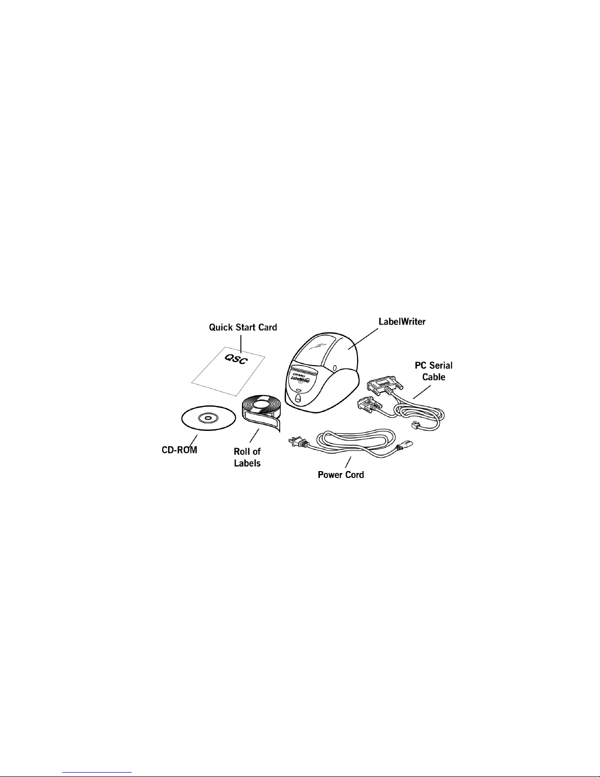
You should find the following items (shown in Figure 1-1):
.Figure 1-1
Check to see if anything is missing or damaged. If there is a
problem, contact Dymo-CoStar immediately. Be sure to save all
the original packing materials. They are especially designed to
protect the printer and will make re-packing easy if you ever need
to ship the printer.
Also note that your LabelWriter does not use toner or ink
cartridges, or a ribbon to print. The LabelWriter is a direct
thermal printer. Direct thermal printers transfer heat from a
1-1
thermal print head to specially treated labels to print. The only
supplies you will ever need to replace with this printer are labels.
Connecting the Power
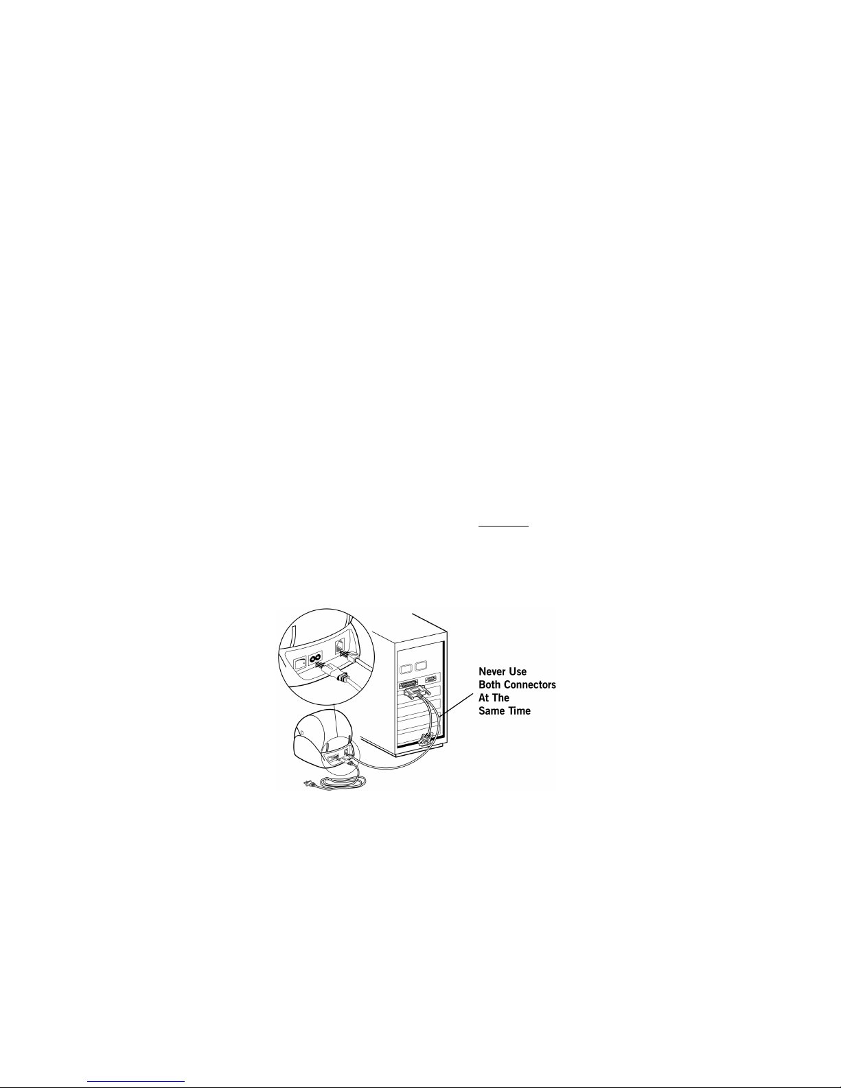
You connect the power cord to the rear of the printer as shown in
Figure 1-2. Plug the other end to a power outlet. The LabelWriter
printer has an internal power supply that can accept any voltage
between 100 and 250 volts (50/60Hz). As a result, the printer can
be used worldwide.
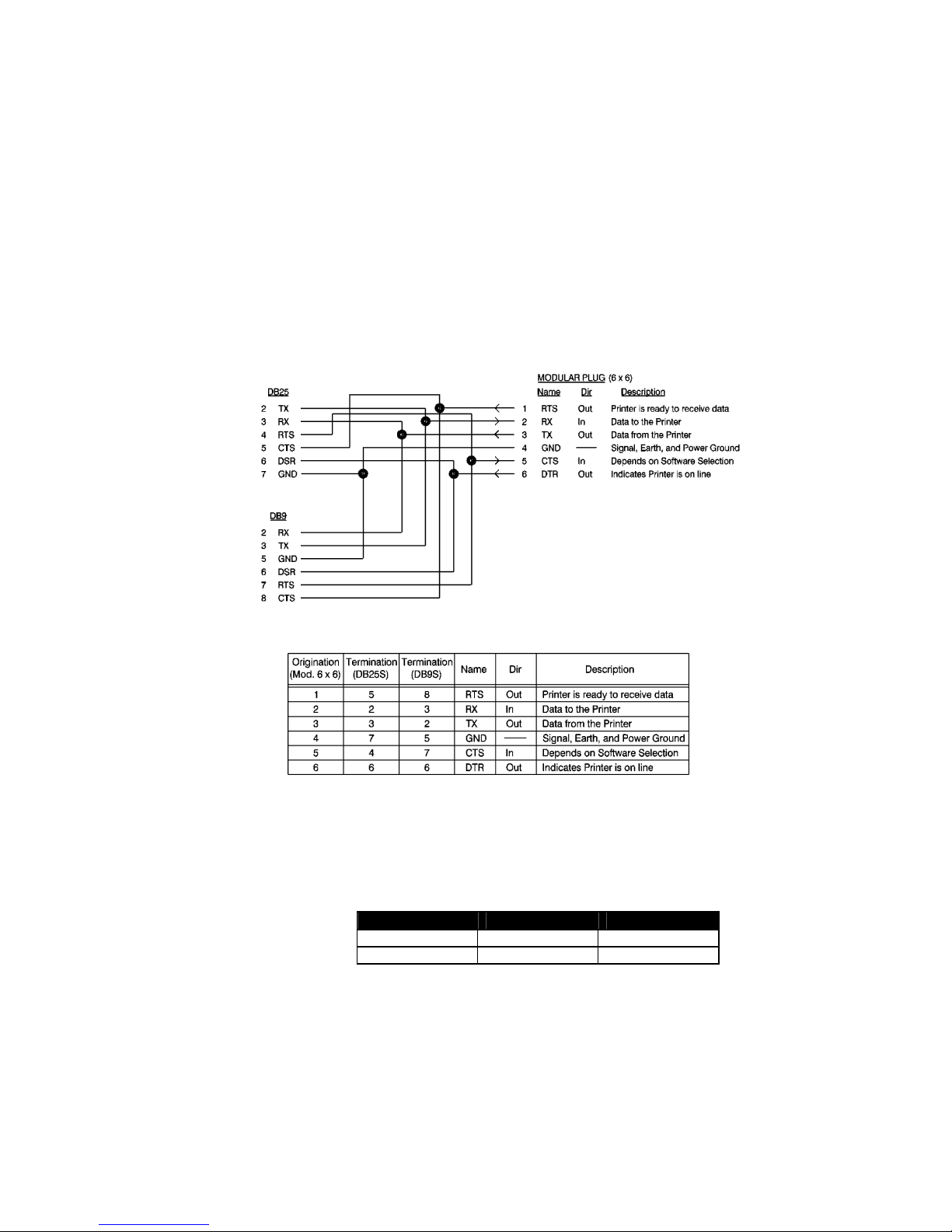
Connecting the Serial Cable
Your printer and computer communicate through the special
serial cable that comes with your LabelWriter. (A parallel cable
option is also available. Call Dymo-CoStar for details.) The serial
cable has a telephone-like connector at one end that plugs into the
back of the LabelWriter, and two serial connectors at the other
end – a 9-pin connector and a 25-pin connector. Your PC will use
one or the other of these two connectors, not both
Follow the steps below while referring to Figure 1-2 to make the
proper connections:
.
1. Turn off your computer and printer.
Figure 1-2.
2. Connect the printer end of the serial cable to the port in the
rear of the printer. It fits only one way, just like a telephone.
1-2

3. If you have a 9-pin serial port on your computer, attach the 9pin connector; if you have a 25-pin serial port, attach the 25pin connector. Secure the connector with the two screws. The
connector you do not use can simply hang loose. See Figure
1-2.
Loading Labels
Follow the instructions below to load labels into the LabelWriter
printer.
1. Open the cover so that you have access to the interior of the
printer. Remove any packing material and press the form feed
button to eject the test label that protected the print head
while in transit..
2. Remove the label spool by lifting it straight up from the spool
holder.
3. The spool has two distinct parts. The part with the center
shaft must always be installed on the left side of the
printer when viewed from the front.
4. Remove the right side of the spool by sliding it off the center
shaft.
5. Locate a roll of labels and remove the tape from the end of
the roll. Cut the lead label in half to create a nice straight
edge. The LabelWriter printer grabs a straight edge much
easier than a rough edge.
6. Refer to Figure 1-3 while following these instructions: Slide
your roll of labels over the spool from right to left as shown
in Figure 1-3a. (The labels should roll out from the bottom of
the spool.) Then, re-attach the right side of the spool and push
it firmly against the label roll. If you’re using address labels
or other narrow labels, your spool will look like Figure 1-3b.
If you’re using shipping or other wide labels, your spool will
look like Figure 1-3c.
1-3
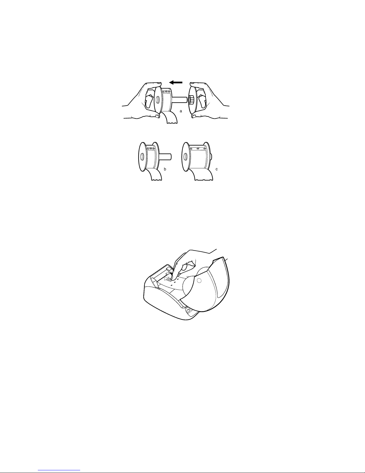
Figure 1-3. Loading labels onto the label s pool.
7. Make sure that the power cord is connected. Turn on the
printer. The green power light will flash and you will hear the
printer’s motor turning as it looks for labels to feed.
8. Place the spool inside the top cover of the LabelWriter, then
thread the lead label of the roll into the feed slot on the inside
of the printer base (See Figure 1-4).
9. Push the end of the label into the feed slot until the motor
grabs it and advances the labels through the printer and out
the exit slot, stopping automatically at the end of the first
label.
1-4
Figure 1-4. Hold the labels in one hand. Use the other hand to
guide the labels into the label f eed slot.

Figure 1-5. Labels loaded, ready to print.
10. Close the cover and your LabelWriter printer is ready to print
labels.
Replacing a Label Roll
To replace an empty roll, or switch between different labels,
follow these instructions:
1. Tear off any labels that have been fed through the printer.
2. Open the cover
3. As you lift the platen release lever, pull the label out of the
platen mechanism. (See Figure 1-6 below)
1-5
Figure 1-6. Push the platen release lever up as you pull the label
back from the m echanism.

1-6

Chapter 2
Setting Up the Host
RS-232 Settings
In order for the host computer to communicate with the
LabelWriter SE300 printer, the communication parameters must
be set as follows:
•= Baud Rate: 9600
•= Data Bits: 8
•= Stop Bits: 1
•= Parity: None
On a computer running DOS, you can use the MODE command
to configure a serial port. To do this, type the following at the
DOS prompt:
MODE COM#: 96,N,8,1,P
where COM# is the serial port you are using. This could be
COM1, COM2, or any valid COM port.
Most compilers provide a command or function to initialize a
serial port. In the BASIC programming language, use the
following command:
OPEN “COM:9600,N,8,1” FOR OUTPUT AS #1
In Microsoft C/C++, use the function:
bios_serialcom().
Other C compilers offer a similar function. Consult your compiler
user guide for the appropriate function to use to configure a serial
port.
If you are using the Unix OS, you’ll need to configure the RS232
port as a dumb printer port, with no special handling, control
characters or form feeds. The LabelWriter will handle these
functions internally.
4-7
Cabling
RS-232 Signal Levels
The serial interface uses standard RS-232 signal levels as shown
in Table 2-1.
4-8
Signal Level Input Output
MARK (1) -27V to -5V -5V
SPACE (0) +5V to +27V +12V
Table 2-1. RS-232 signal levels.

Chapter 3
Programming Overview and Notes
About This Chapter
This chapter covers all the points that need to be understood in
order to program the LabelWriter correctly.
Both basic and advanced topics will be explained so that you get
a clear idea of how the LabelWriter work.
Programming for the LabelWriter
The first step in programming the LabelWriter is to understand
how the printer works.
As an ASCII-bas ed prin ter, t he Labe lWrit er accepts 8-bit ASCII
characters as both data and commands. The ASCII table in
Appendix G shows the relationship between the 8-bit values and
the characters they represent. Most environments either use the
ASCII character table as the default for character values or
support an ASCII mode where characters are interpreted by the
ASCII values. This means that sending data and commands to the
printer is usually as simple as transmitting the characters from
your program to the port to which the LabelWriter is connected.
A simple program to print ‘Hello World’ on the LabelWriter
might look as follows in Qbasic for DOS.
OPEN “COM1:9600,n,8,1” FOR OUTPUT AS #1
PRINT #1, “HELLO WORLD”
The “OPEN…” line above opens the selected COM port for
printing and initializes the communication settings while the
“PRINT…” line sends the data to the printer.
Commands can be sent to the printer in exactly the same way. For
example, if you wanted to change the font which “Hello World”
was printed into a 7-characters-per-inch font, you could look in
this manual and find that the required command characters to do
this are ESC and T. (ESC refers to the Escape character. By
checking Appendix G, you would find that the ESC character has
4-9

a decimal value of 27.) With this information, you can construct
the following program to print ‘Hello World’ in a 7-charactersper-inch font.
OPEN “COM1:9600,n,8,1” FOR OUTPUT AS #1
PRINT #1, CHR$(27); “T”;
PRINT #1, “HELLO WORLD”
In a nutshell, that’s all there is to programming for the
LabelWriter. Any formatting or special effect that you may need
for your output can be specified simply and easily by sending the
appropriate command characters and the data to be printed.
Below, we’ll cover the ins, outs and general information that you
should know before programming the LabelWriter.
Resetting the Printer
Each print job should begin with a printer reset command. This
ensures that the printer always begins in a known state.
The command characters used to reset the LabelWriter are ESC
(decimal value 27) and * (decimal value 42).
Command Parameters
When sending a command, all of the command characters and
parameters that make up a command must be sent. This is
especially important when using the bar code and graphics
commands. Sending too few characters to fill the required
parameters for a command will either cause the command to fail
or result in subsequent data being lost.
Character Evaluation
Most of the parameters that are sent to the LabelWriter are
evaluated based on their decimal value. It is very important to
have a good understanding of what this means.
The ASCII character that is represented by a ‘3’ does not have a
decimal value of 3 (the character '3's decimal value is 51, as listed
in the ASCII table in Appendix G).
4-10

Similarly, a parameter cannot be given a value of 32 (for
example) by sending the ASCII character represented by ‘3’ and
the ASCII character represented by ‘2.’
By referencing the ASCII table, you will notice that the space
character has a decimal value of 32. Therefore, to set a parameter
to a value of 32, you should send a space character.
Some commands accept parameters by either their decimal value
or the representative character. For example, the set print
orientation command (GS V) interprets both a NULL (ASCII
decimal value of 0) and the ‘0’ character as meaning the same
thing. This was done to ensure backwards compatibility with the
original LabelWriter SE and should not be assumed to be true for
all commands in general.
16-Bit Character Parameters
The maximum value a single 8-bit character can represent is 255.
Some commands, though, can take values that are greater than
255. The set horizontal starting position command (ESC X), for
example, specifies a distance (in dots) that the next text object
will print from the left margin. Because a dot is only 1/8
millimeter, a value of 255 would place the object only a little over
31mm from the left margin. To allow for longer distances to be
specified, two 8-bit characters are used to specify the value, by
combining them into one 16-bit character. Though the
calculations are all done within the LabelWriter, it is important to
understand how the characters are handled.
th
of a
The decimal value of the first character that is sent (usually noted
as n1) is multiplied by 256. The decimal value of the second
character sent (usually noted as n2) is then added to this.
4-11
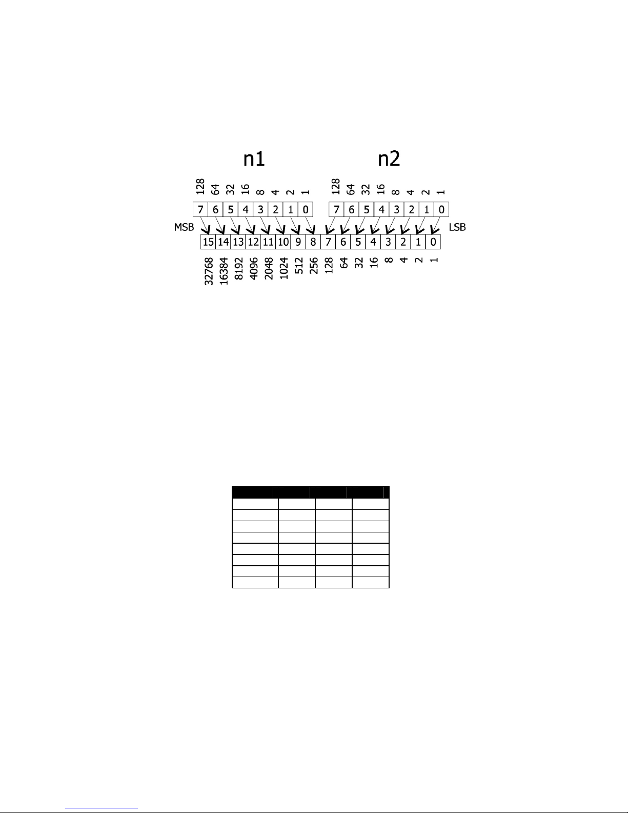
Below is a graphical representation of how this works.
To send a value under 256 to a command that takes the n1 n2
parameters, simply send the first character with a 0 value. For
values greater than 256 but less than 512, the first parameter
should be sent with a value of 1. For values greater than 512 but
less than 768, the first parameter should be set to 2, and so on.
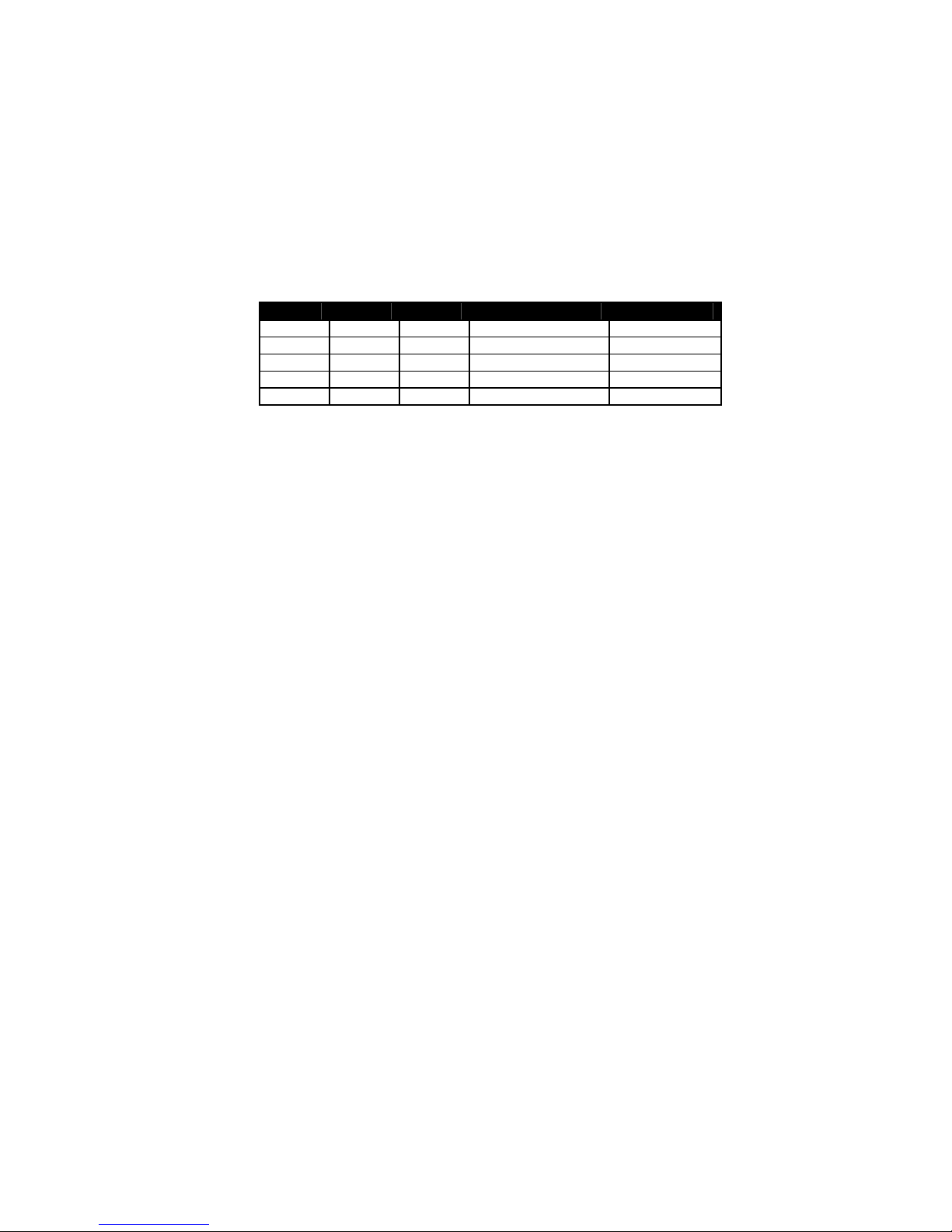
Conversions
Converting from dots to inches using the n1 n2 parameters can
seem a bit challenging at first, but is really no more complex than
multiplication and division. The table below lists some common
values and their relationship.
Inches Dots n1 n2
0.5 101 0 101
1.0 203 0 203
1.5 304 1 48
2.0 406 1 150
2.5 507 1 251
3.0 609 2 97
3.5 710 2 198
4.0 812 3 44
4-12
Font Statistics
The table below lists the statistics for the 5 internal fonts the
LabelWriter supports. Height and Width are expressed in terms of
dots.
Font Height Width Horizontal cpi Vertical cpi
ESC S 16 10 20.3 12.7
ESC P 24 12 16.9 8.4
ESC M 32 16 12.7 6.4
ESC U 32 20 10.2 6.4
ESC T 56 28 7.3 3.6
Objects
Objects are the basic units that the LabelWriter prints. An object
can be either a line of text characters, a bar code, a landscape
graphic, a landscape line, or an EL dot line. Each of these objects
has different rules relating to them, as discussed below.
Objects can also be either active or completed. An active object is
one that is still receiving the data that composes it. A completed
object is one that has been terminated. A line of text that has not
yet received a line feed or carriage return is a good example of an
active object. Until a terminator character, like a line feed, is sent,
more text characters can be added to the text object. Bar code
and graphic objects do not require special terminator characters
(such as line feeds). Instead they are considered complete as soon
as they receive the correct amount of data.
Print Modes
Before we move on to discuss the specific objects that the
LabelWriter supports, it is important to cover the different print
modes in which the LabelWriter may print the objects.
The LabelWriter possesses three modes of printing: EL (bitmap
graphics) mode, portrait printing mode, and landscape printing
mode. Each mode operates under very different rules. These rules
are detailed below.
4-13
EL Mode
The LabelWriter SE300 command sets includes the entire
command set of the LabelWriter EL, as well as the ASCII
commands that will be discussed later. EL mode refers to printing
using the LabelWriter EL printing commands. Because the
LabelWriter EL commands are an inherent part of the
LabelWriter SE300, there are no special commands to switch to
LabelWriter EL emulation. Data may be sent exactly as though it
were being sent to a LabelWriter EL and the LabelWriter SE300
will process it and print correctly.
At its most basic level, a LabelWriter is a direct thermal printer
that creates images on a label by heating the individual elements
of its print head. On a LabelWriter SE300, the print head has 448
elements (or dots). When it prints, some of these dots will be
turned on (heated), and the printer’s motor will advance the paper
by a step. Any thermal paper that is under a heated element will
then turn black. For each motor step, a dot line is printed. By
controlling the length of each step, the LabelWriter can print in
either 203x203 dpi or 203x138 resolution, as a longer step makes
larger dots and therefore results in lower resolution.
Each dot line is a complete object and is printed by the
LabelWriter as soon as it is processed. Because of this, an EL dot
line should not be sent while a portrait object or a landscape page
is being constructed.
4-14

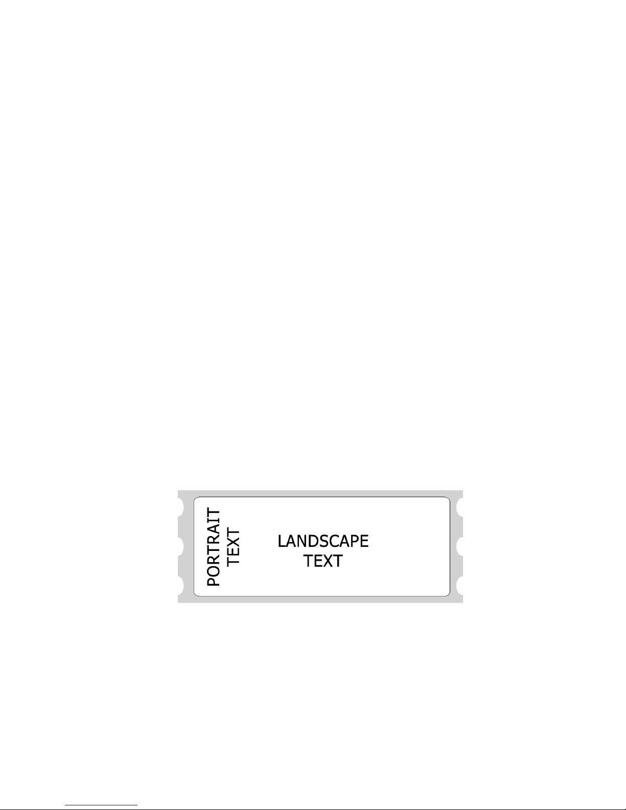
Portrait Mode
On power-up, the LabelWriter is set for portrait printing. In
portrait mode, text characters travel out of the printer from the top
of the character to the bottom. It is also possible to switch to this
mode using the set print orientation command (GS V).
Portrait mode is also referred to as immediate mode printing,
because each object that is sent to the printer while the printer is
in portrait mode is printed as soon as the object is completed. No
two objects may be printed on the same line in this mode because
the paper is advanced as each object is completed and printed.
Certain commands are disabled or work differently while the
LabelWriter is in portrait mode. Exact details can be found under
each command’s description.
Landscape Mode
By using the set print orientation command (GS V), you can
configure the LabelWriter for landscape printing. In landscape
printing, text characters travel out of the printer from the left side
of the character to the right. Before the LabelWriter can be
switched to landscape printing, though, you must send the set
characters per line command (GS t). The set characters per line
command defines the width of the landscape page.
A landscape page is defined as the area allocated by the
LabelWriter in which landscape text, graphic, bar code, and line
objects may be printed. The height of this landscape page always
equals the width of the Label Writer’s print head. The width of
the landscape page is calculated when the set characters per line
command (GS t) is sent. The width of the page is equal to the
number of characters per line multiplied by the width of the
current font. The default font is 16 dots wide (2mm) and the
default number of characters per line is 80.
In landscape mode, completed objects are placed within a
memory buffer in the LabelWriter and are only printed when the
landscape page is terminated. A form feed (FF) character is
usually used to terminate a landscape page. This causes the
LabelWriter to print the objects that have been placed on the
landscape page and advance to the next label.
4-15

After a landscape page is printed, the LabelWriter will remain in
landscape mode. If more objects are sent to the LabelWriter, a
new landscape page will be allocated, with a width equal to the
previous page. To change the width of a landscape page, you
must send the set characters per line command (GS t) followed by
the set print orientation command (GS V).
Because the LabelWriter does not print objects immediately,
multiple objects can be placed on the same line. The set
horizontal starting position (ESC X) and set vertical starting
position (ESC Y) commands allow objects to be placed at any
location within a landscape page. In the case of objects that are
positioned to overlap each other, the first object that is sent to the
printer will be printed in the overlapping area.
Objects that would normally print below the bottom of the
landscape page can be either wrapped to the next label or
truncated by using the select line wrap/truncate modes command
(GS T).
Unless the set vertical starting position command (ESC Y) is
used, the first object sent will be printed at the top of the
landscape page. When using labels that are narrower than the
LabelWriter’s print head, the top of the landscape page will be
above the top of the label stock. In these cases, you should use the
set vertical starting position command (ESC Y) to position the
object on an area of the landscape page that corresponds to the
label.
General Notes on Print Modes
The LabelWriter may be in only one print mode at a time.
Multiple areas may be printed in different print modes on a single
label, but these areas may only be adjacent to one another, they
may not overlap.
In any mode, the set feed length command (GS L) is used to
determine how far the LabelWriter will feed in search of a top-ofform hole. If the LabelWriter finds a top-of-form hole before this
maximum feed distance is reached, it will stop at that point, rather
than continuing. This command is only needed when dealing with
continuous-feed paper.
4-16

Text Objects
A text object is simply a line of printable characters. A text object
is created whenever the LabelWriter receives a printable
character that is not otherwise part of a command. Once it’s
created, a text object will remain active until it is terminated.
While a text object is active, any printable characters sent to the
LabelWriter will be added to that text object. The only exceptions
are printable characters that are sent as part of a command. While
a text object is active, commands that alter text line attributes
(such as font and double-height character commands) are ignored.
Commands that alter text character attributes (such as double
wide and inverse) may be sent at any time, though.
Line attributes include the five basic fonts (ESC S, P, M, U, and
T), plus the double-height font command (GS DC2). These
commands may not be issued while a text object is active; instead
they should be issued before a text object is begun. The font line
attribute persists until another font command is received. The
double-height line attribute persists either until the cancel double
height command (GS DC3) is sent or the current font is changed.
The character attribute commands include the set font to double
wide (SO) and set inverse print mode (GS RS) commands. These
commands may be issued or canceled at any time. Character
attributes persist only until the end of a text object.
A text object can be terminated with a carriage return, a line feed,
or both, in either combination. If the length of the text object
exceeds the space allowed for printing, it will either wrap to the
next line or truncate at the end of the printable area. The decision
to wrap or truncate is determined by the select line wrap/truncate
mode command (GS T). By default, text objects will wrap to the
next line.
Bar Code Objects
A bar code object is created by the print bar code command
(GS k). Specified within the command is the symbology to be
used, the amount of data to be encoded, and the data itself. Other
4-17

attributes of the bar code, such as height and width, can be set
using other commands.
The set bar code height command (GS h) specifies the height of
the bar code in dots, or 1/8
th
mm. The maxi mum hei ght f or a bar
code is 256 dots, or 32mm. In cases where a taller bar code is
needed, a second bar code can be printed below the first at the
same left offset.
The set bar code module width (GS w) and set bar code element
width (GS W) commands can be used to alter the width of the bar
code. See the command descriptions later in the next chapter for a
full explanation of the differences between these two commands.
The POSTNET bar code symbology is an exception and does not
respond to any of these commands. Instead, it always prints
within the U.S. Postal Service’s specifications.
The limitations of each symbology must be adhered to when
sending data for a bar code. For example, you should not send
alphabetic characters to symbologies that only accept numeric
data (like the UPC/EAN symbology).
Other items must also be considered when printing bar codes.
You must leave sufficient blank space on either side of the bar
code to create a quiet zone. You must also select a good
ratio/element size if the default values are not being used, and you
must allow adequate room for the bar code to be printed on the
label. If you ignore any of these items, the bar code that is printed
may be unreadable.
A bar code object is self-terminating and will be processed as
soon as the proper amount of data has been sent to it. The print
bar code command’s (GS k) second parameter specifies whether a
fixed amount of data will be sent or whether delimiters will be
used. In either case, the data sent must match the parameter
setting. If a fixed number of characters are specified, then the
exact number of characters specified must be sent. If delimiters
are indicated, then matching characters must be sent before and
after the bar code data to specify the beginning and end of the
data. If an incorrect number of characters or delimiters are sent,
the LabelWriter will not print correctly.
4-18

Bar codes that are too long to fit within the printable area of a
label are truncated. This usually results in an unreadable bar code
being printed. To correct this condition, you must set a narrower
ratio, encode fewer digits, or use a more compact symbology.
Graphic Objects
Graphic objects are created by the landscape mode graphics
command (GS *).
Graphic objects may only be printed as part of a landscape page.
To print a graphic without entering landscape mode, you must use
EL mode graphic commands.
No landscape graphic may be wider than 256 dots, though they
may be as tall as the width of the LabelWriter’s print head. If you
need to print a graphic wider than 256 dots, you must either
subdivide it into narrower sections or print it using EL mode
graphics commands.
For more information about landscape graphic objects, see the
descriptions of the graphics commands in this manual.
Line Objects
Line objects are created using the draw line in landscape mode
command (GS l).
Line objects may only be printed as part of a landscape page. If
the length of a line object is set to exceed the printable area of a
label, the line will be truncated at the end of the printable area.
4-19

Chapter 4
LabelWriter Command Reference
About This Chapter
This chapter describes the commands you can use to program
your LabelWriter SE300 printer. Below are some of the things
you can do with the commands:
•= Send linefeeds and carriage returns
•= Define bar code size and position
•= Return firmware revision and printer status information
•= Define label size, and paper orientation
•= Print graphics in inverse text mode and print enlarged
characters
See the pages that follow for listings of listings of commands
arranged alphabetically and by function.
4-20

SE300 Commands Alphabetical List
NAME DESCRIPTION PAGE
HT Horizontal Tab 26
LF Line Feed 27
FF Form Feed 28
CR Carriage Return 29
SO Set Font to Double Wide 30
DC4 Cancel Double Wide Mode 31
SYN EL Mode Graphics 32
ETB EL Mode Compressed Graphics 34
20h - FFh Printable Characters 36
ESC * Reset to Defaults 37
ESC @ Reset to Power-up Condition 38
ESC A Return Printer Status 39
ESC B Set Dot Tab 40
ESC D Set Bytes per Line 41
ESC E Form Feed 42
ESC F 1 Feed Sublines 43
ESC J n Feed n Sublines 43
ESC L Set Feed Length 45
ESC M Set Font to 12 cpi 46
ESC P Set Font to 16 cpi 47
ESC Q Set Top Margin 48
ESC S Set Font to 20 cpi 49
ESC T Set Font to 7 cpi 50
ESC U Set Font to 10 cpi 51
ESC V Return Firmware Revision 52
ESC W n1 n2 Wrap Data 53
ESC X n1 n2 Set Horizontal Starting Position 54
ESC Y n1 Set Vertical Starting Position 55
ESC a Return Hardware Status 56
ESC F 1 Feed Sublines 43
ESC y Set 203 x 203 dpi 56
ESC z Set 136 x 203 dpi 56
GS DC2 Set Font to Double Height 57
GS DC3 Cancel Double Height 58
GS RS Set Inverse Print Mode 59
4-21

NAME DESCRIPTION PAGE
GS US Cancel Inverse Print Mode 60
GS * n1 n2 t h w d1…dm Landscape Mode Graphics 61
GS A n1 n2 Bar Code Start Position 62
GS L n1 n2 Set Feed Length 64
GS S Return Printer Status 65
GS T n Select Line Wrap/Truncate Modes 66
GS V n Set Print Orientation 67
GS W Thin Thick Set Bar Code Element Width 68
GS d n Feed n Text Lines 69
GS h n Set Bar Code Height 70
GS k n m d1…dk Print Bar Code 71
GS l n1 n2 l1 l2 m Draw Line in Landscape Mode 73
GS q n m d1…dk P rint UPC/EAN Checksum 76
GS t n Set Characters per Line (Landscape) 77
GS u n Set Characters per Line (Portrait) 78
GS w n Set Bar Code Module Width 79
GS x Print MaxiCode Bar Code 80
GS ~ Enter Debug Mode 81
4-22

SE300 Commands by Function
Position Control
HT Horizontal Tab 24
LF Line Feed 27
FF Form Feed 28
CR Carriage Return 29
ESC J n Feed n Sublines 43
ESC X n1 n2 Set Horizontal Starting Position 54
ESC Y n1 Set Vertical Starting Position 55
GS T n Select Line Wrap/Truncate Modes 66
GS V n Set Text and Bar Code Orientation 67
GS d n Feed n Text Lines 69
GS t n Set Characters per Line (Landscape) 77
GS u n Set Characters per Line (Portrait) 78
Printable Characters
20h - FFh Printable Characters 36
Font Control
ESC T Set Font to 7 cpi 50
ESC M Set Font to 12 cpi 46
ESC P Set Font to 16 cpi 47
ESC S Set Font to 20 cpi 49
ESC U Set Font to 1 0 cpi 51
ESC X n1 n2 Set Horizontal Starting Position 54
SO Set Font to Double Wide 30
DC4 Cancel Double Wide Mode 31
GS DC2 Set Font to Double Height 57
GS DC3 Cancel Double Height 58
GS RS Set Inverse Print Mode 59
GS US Cancel Inverse Print Mode 60
4-23

Bar Codes
GS A n1 n2 Bar Code Start Position 62
GS W Thin Thick Set Bar Code Element Width 68
GS h n Set Bar Code Height 70
GS k n m d1…dk Print Bar Code 71
GS w n Set Bar Code Module Width 79
GS x Print MaxiCode Bar Code 80
Miscellaneous
ESC @ Reset to Power-up Condition 38
ESC V Return Firmware Revision 52
ESC W n1 n2 Wrap Data 53
GS ~ Enter Debug Mode 81
GS * n1 n2 t h w d1…dm Landscape Mode Graphics 61
GS L n1 n2 Set Feed Length 64
GS S Return Printer Status 65
GS l n1 n2 l1 l2 m Draw Line in Landscape Mode 73
EL Compatibility
SYN EL Mode Graphics 32
ETB EL Mode Compressed Graphics 34
ESC * Reset to Defaults 37
ESC @ Reset Printer to Po wer-up Condition 38
ESC A Return Printer Status 39
ESC B Set Dot Tab 40
ESC D Set Bytes per Line 41
ESC E Form Feed 42
ESC L Set Feed Length 45
ESC Q Set Top Margin 48
ESC a Return Hardware Status 56
ESC F 1 Feed Sublines 43
ESC y Set 203 x 203 dpi 56
ESC z Set 138 x 203 dpi 56
Command Reference
The commands are listed by name in alphabetical order. Each
section contains a description of the command. The ASCII,
4-24

hexadecimal, and decimal values for each command are also
provided.
See Appendix A for examples (in the BASIC computer language)
of how the commands are used
See Appendix G for a list of ASCII, hexadecimal, and binary
codes.
4-25

HT Horizontal Tab
DESCRIPTION
Moves cursor position to next multiple of eight single-width
characters. Note that double-width characters count as two singlewidth characters. If the HT command causes the cursor to move
beyond the printable area, the text will wrap to the next line.
EXPRESSION
ASCII HT
Decimal 9
Hex 9
PARAMETERS
None
EXAMPLE
For an example of this command’s usage, see Appendix A, page
83, Example 1.
For an example of this command using the Caret feature see page
94, Example 1
4-26
 Loading...