

Page 1

D
Infinity Configured Monitoring Series
Infinity Gamma Series
User’s Guide
Page 2

Draeger Medical Systems, Inc.
16 Electronics Avenue
Danvers, MA 01923
USA
Authorized EC representative:
Dräger Medical AG & Co. KGaA
Moislinger Allee 53-55
23558 Lübeck
Germany
Infinity Gamma Series User’s Guide
Software Version VF4
This product is covered by one or more of the following patents: 5,224,484;
5,224,740; 5,240,008; 5,285,791; 5,355,890; 5,337,751; 5,375,604.
This device bears the ! label in accordance with the provisions of the Directive 93/42/EEC of June 14, 1993 concerning medical devices.
0123
!"
Dräger Medical AG & Co. KGaA, 2003. All rights reserved.
Printed in the United States of America.
Dräger reserves the right to modify the design and specifications contained
herein without prior notice. Please contact your local Dräger Sales Representative for the most current information.
Reproduction in any manner, in whole or in part, in English or in any other
languages, except for brief excerpts in reviews and scientific papers, is prohibited without prior written permission of Dräger Medical AG & Co. KGaA.
All Dräger devices are intended for use by qualified medical personnel only.
CAUTION: Federal Law in the United States restricts these devices to
sale by, or on order of a physician.
Before using all Dräger devices, read all the manuals that are provided with
your device carefully. Patient monitoring equipment, however sophisticated,
should never be used as a substitute for the human care, attention, and critical
judgment that only trained health care professionals can provide.
Page 3

What’s New
The functionality of the Infinity Gamma Series patient monitor
has been improved and expanded to include the following new
features in software version VF4:
! Support of gas monitoring functions in anesthesia and operat-
ing room environments. The Gamma XL can now display
concentrations of CO
halothane, isoflurane, enflurane, sevoflurane, and desflurane.
The Gamma XL receives these gas values from a Dräger Scio
multigas module. Note: This functionality is only available
for the Gamma XL (and not the Gamma). For information
about multigas monitoring, see Chapter 14, Multigas.
! Support of network laser printers. Recording requests can be
sent from the Infinity Gamma Series monitor via the Infinity
network to a network laser printer. For information about
recording functions, see Chapter 7, Recordings.
, N2O, O2 and of the anesthetic agents
2
! Improved SpO
performance during motion artifact. For
2
information about pulse oximetry, see Chapter 12, Pulse
Oximetry.
NOTES:
The Gamma XL monitor with Anesthetic Gas Monitoring
!
requires FDA 510(k) review.
! The Gamma XL monitor with Anesthetic Gas Monitoring is not
yet licensed in accordance with the Canadian Medical Devices
Regulations.
VF4 Infinity Gamma Series Page iii
Page 4

Infinity Gamma Series Software Release Notes
Software Version VF4
! Wireless network operation requires special configurations of the monitor-
ing network and the MULTIVIEW WORKSTATION (a service function). If
you experience problems with wireless network operations, contact your
Service personnel.
! When moving and assigning a wireless monitor to a different central sta-
tion, the original central station may emit a brief network error tone and
display an Offline message instead of the message Bed Disconnected.
However, there is no disruption of network monitoring and the Offline
message clears as soon as you assign a new bed to the central viewport.
! When you change the units of measure at the bedside and the central sta-
tion is showing the monitor’s bed view, you must first exit the central bed
view, before the change of units appears at the central station.
! For network and card data transfer:
— Occasionally, after a data transfer from an Infinity Delta Series monitor,
you may see three or four ST trends instead of the two ST leads monitored
by the Infinity Gamma Series monitor.
! For network data transfer only:
— If ST is enabled, the ST data transferred from an Infinity Delta Series
monitor (VE0) or from a M
I and II, regardless of the ST leads selected on the Infinity Gamma Series
monitor. Note: Other ST data will be permanently lost.
— After a network transfer of telemetry data to an Infinity Gamma Series
monitor, ST trend points may appear two minutes apart.
— The IBP data transferred from an Infinity Delta Series monitor (VE0) to
an Infinity Gamma Series monitor is labelled GP1 and GP2.
! NBP parameter values transferred from an Infinity Gamma Series monitor
to an Infinity Delta Series monitor will be displayed in the trend graphs
rather than in the trend tables of the destination monitor.
! On rare occasions, a docked monitor may reset when entering the
Transfer Menu under certain network conditions. The monitor returns
to the state prior to the reset within 30 seconds.
ULTIVIEW Telemetry System (VE0) is ST lead
! When power-cycling the monitor or admitting a new patient, saved moni-
toring settings may occasionally return to default settings. Check monitoring settings after these events.
! If the Scio module is unable to measure the concentration of N
itor may enter the error code *A* (artifact) instead of *F* (failure) into the
O, the mon-
2
trend storage.
Page iv Infinity Gamma Series VF4
Page 5

!
Occasionally, the ECG waveform is not displayed in the second waveform
channel, when you assign SpO2 to the first waveform channel. In this case,
click on the second waveform channel and select the desired ECG lead
again.
! When admitting a patient at the MULTIVIEW WORKSTATION, the monitor
does not store the admit date, if it is the current date. In this case, you must
enter the admit date via the monitor’s Patient Admit menu.
! When the values of an anesthetic agent exceed the measuring range, the
monitor displays +++ in the agent parameter box and cycles two out-ofrange error messages, one correctly identifying the agent with out-ofrange values, the other showing a previously monitored agent.
VF4 Infinity Gamma Series Page v
Page 6
Documentation Features
Notes, Cautions, Warnings
NOTE: A note presents information that helps you operate the
equipment or connected devices.
CAUTION: A caution provides information or instructions that
must be followed to ensure proper operation and performance of
the equipment
WA RN I NG : A warning contains important information
regarding possible danger to you or the patient that is
present during normal operation of the equipment.
.
Page vi Infinity Gamma Series VF4
Page 7

Chapter Overview
Chapters
Overview....................................................................................1
Monitor Setup ........................................................................... 2
Network Applications............................................................... 3
Admission, Discharge, Transfer.............................................. 4
Alarms and Messages.............................................................. 5
Trends........................................................................................ 6
Recordings................................................................................ 7
ECG and Heart Rate ................................................................. 8
Arrhythmia ................................................................................ 9
ST-Segment Analysis ............................................................. 10
Respiration.............................................................................. 11
Pulse Oximetry ....................................................................... 12
End-Tidal CO2.........................................................................13
Multigas................................................................................... 14
Non-Invasive Blood Pressure................................................ 15
Invasive Blood Pressure........................................................ 16
Temperature ............................................................................ 17
Appendices
Options and Accessories ....................................................... A
Cleaning, Disinfecting, Sterilizing.......................................... B
Default Settings and Biomedical Support............................. C
Technical Data ......................................................................... D
Glossary
Index
VF4 Infinity Gamma Series Page vii
Page 8

Table of Contents
Overview
Important General Safety Considerations .................................... 1-2
Electromagnetic Compatibility ................................................ 1-2
Reducing EMI ............................................................................1-3
Site of Operation .......................................................................1-3
Electrical Safety ........................................................................ 1-4
Connections to Peripheral Devices.........................................1-4
Safety, Inspection, and Maintenance ......................................1-5
Electrosurgery and Defibrillation Safety ................................1-6
Pacemaker Safety .....................................................................1-6
Device Markings........................................................................1-7
General Description........................................................................1-8
Front Panel ....................................................................................1-10
Back Panel.....................................................................................1-11
Left Side Panel ..............................................................................1-12
Right Side Panel............................................................................1-13
Interface Plate (optional)..............................................................1-14
Infinity Gamma Display ................................................................1-15
Alarm Colors ...........................................................................1-15
Display Colors.........................................................................1-16
Rotary Knob ..................................................................................1-17
Fixed Keys.....................................................................................1-18
Menus.............................................................................................1-19
Power Sources ..............................................................................1-20
MultiMed/NeoMed Pod..................................................................1-21
etCO2 Pod and Multigas Module................................................. 1-22
Recorder ........................................................................................1-22
Remote Displays...........................................................................1-23
Monitor Setup
Getting Started ................................................................................2-2
Using the AC Adapter...............................................................2-2
Using the Battery ......................................................................2-4
Assembling MultiMed and NeoMed Pods...............................2-9
Page viii Infinity Gamma Series VF4
Page 9

Starting the Monitor......................................................................2-10
Main Screen Configuration ..........................................................2-11
Waveform Selection................................................................2-11
Bottom Channel Display.........................................................2-12
OR Mode ..................................................................................2-15
Show Respiration or etCO2 Parameters...............................2-16
Setting Date and Time ..................................................................2-17
Setting the Master Speaker Volume............................................2-18
Turning External Alarm Lights ON/OFF......................................2-19
Standby..........................................................................................2-20
Saving Setups ...............................................................................2-21
Network Applications
Overview ..........................................................................................3-2
Network Configurations .................................................................3-3
Basic Network Components ....................................................3-4
Basic Bedside Setups...............................................................3-5
Network Operation..........................................................................3-6
Docking Station.........................................................................3-7
Docking and Undocking ...........................................................3-9
Wireless Network Configuration............................................3-11
Wireless Network Operation ..................................................3-13
Network Safety Considerations...................................................3-16
Alarm and Status Messages ........................................................3-17
Admission/Discharge/Transfer
Overview ..........................................................................................4-2
Patient Admission...........................................................................4-3
Admit Menu................................................................................4-4
Patient Category........................................................................4-5
Name and ID ..............................................................................4-6
Admit Date .................................................................................4-8
Patient Discharge............................................................................4-9
Data Transfer.................................................................................4-10
Transfer Across the Network.................................................4-11
Transfer with a Data Memory PC Card..................................4-13
VF4 Infinity Gamma Series Page ix
Page 10

Alarms and Messages
Alarm Grades ..................................................................................5-2
Life-Threatening Alarms...........................................................5-2
Serious Alarms..........................................................................5-3
Advisory Alarms .......................................................................5-4
Alarm Settings.................................................................................5-5
Setting Alarm Limits .................................................................5-6
Turning Parameter Alarms On/Off...........................................5-8
Turning Alarm Recordings On/Off ..........................................5-9
External Alarm Lights...............................................................5-9
Alarm Validation............................................................................5-10
Silencing Alarms...........................................................................5-11
Alarm Silence Key...................................................................5-11
All Alarms OFF Key ................................................................5-12
Assigning Alarm Groups..............................................................5-13
Central Alarms ..............................................................................5-14
Alarms in OR Mode....................................................................... 5-15
Messages.......................................................................................5-16
Trends
Overview ..........................................................................................6-2
Trend Setup.....................................................................................6-3
Trend Graphs ..................................................................................6-4
Trend Table......................................................................................6-6
Special Conditions and Codes ......................................................6-8
Recordings
Overview ..........................................................................................7-2
Recorder Preparation .....................................................................7-3
Assigning Network Recorders.......................................................7-6
Recording Waveforms....................................................................7-7
Timed Recordings.....................................................................7-7
Continuous Recordings ...........................................................7-8
Recording Formats ...................................................................7-9
Recording Trends .........................................................................7-11
Page x Infinity Gamma Series VF4
Page 11

Recording Alarms .........................................................................7-13
Stored Recordings........................................................................7-14
Event Recall.............................................................................7-14
Saving, Printing, Deleting Stored Recordings .....................7-16
Recording Status Messages ........................................................7-17
ECG and Heart Rate
Overview ..........................................................................................8-2
Patient Preparation .........................................................................8-3
Selecting and Preparing the Electrodes .................................8-3
Preparing the Patient’s Skin ....................................................8-3
Positioning the Electrodes.......................................................8-5
ECG Monitoring Settings ...............................................................8-8
Cable Type .................................................................................8-8
Lead Selection and Display Amplitude...................................8-9
Cascade Display......................................................................8-10
One- or Two-Channel Signal Processing..............................8-11
Pulse Tone Source..................................................................8-12
Pulse Tone Volume.................................................................8-13
Pacer Detection.......................................................................8-14
Displaying Sync Marks...........................................................8-15
ECG and HR Safety Considerations............................................8-16
HR Alarm Settings...................................................................8-16
Neonatal ECG Monitoring.......................................................8-16
ECG 50/60 Hz Notch Filter Setting.........................................8-16
Muscle Stimulators .................................................................8-16
Electrosurgery (ESU)..............................................................8-17
Infusion pumps .......................................................................8-19
Defibrillators and Cardioversion ...........................................8-19
High P-Waves and T-Waves...................................................8-19
Pacemakers .............................................................................8-20
AV Sequential or DDD Pacemakers.......................................8-21
Pacemakers with Impedance-Derived Rate Response........8-21
Large Amplitude Pacer Pulses ..............................................8-22
Transcutaneous Electrical Nerve Stimulators (TENS).........8-22
VF4 Infinity Gamma Series Page xi
Page 12

Arrhythmia
Overview ..........................................................................................9-2
Turning Arrhythmia Monitoring ON .............................................. 9-4
Arrhythmia Setup............................................................................9-5
Rate and Count .........................................................................9-6
Arrhythmia Alarms....................................................................9-6
Arrhythmia Alarm Recordings.................................................9-7
Relearning a Patient’s ECG............................................................9-7
ST Segment Analysis
Overview ........................................................................................10-2
ST Monitoring Display .................................................................. 10-3
ST Setup ........................................................................................10-4
Isoelectric and ST Measuring Points .................................... 10-5
ST Reference Complex...........................................................10-7
ST Alarms ......................................................................................10-8
Respiration
Overview ........................................................................................11-2
Patient Preparation.......................................................................11-3
Selecting and Preparing the Electrodes ...............................11-3
Preparing the Patient’s Skin ..................................................11-3
Electrode Placement for Respiration Monitoring ................11-3
Respiration Monitoring Display................................................... 11-5
Displaying Respiration Data .................................................. 11-6
Rsp Display Channel ..............................................................11-7
Resp Display Amplitude.........................................................11-8
Respiration Monitoring Settings .................................................11-9
Rsp Mode.................................................................................11-9
Resp Markers ........................................................................11-10
Apnea Time............................................................................11-11
Coincidence Alarm ...............................................................11-12
Relearning a Patient’s Respiration Pattern ........................ 11-13
Rsp Safety Considerations ........................................................11-14
OxyCRG Monitoring (Neonatal Option) ....................................11-15
Displaying OCRG Waveforms..............................................11-15
OCRG Recordings ................................................................11-17
Page xii Infinity Gamma Series VF4
Page 13

Pulse Oximetry
Overview ........................................................................................12-2
Sensor Application .......................................................................12-2
SpO2 Safety Considerations........................................................12-4
SpO2 Monitoring Display .............................................................12-5
SpO2 Display Channel............................................................12-5
SpO2 Display Amplitude ........................................................12-6
Cascade Display......................................................................12-7
SpO2 Monitoring Settings............................................................12-8
Pulse Tone Source..................................................................12-8
Pulse Tone Volume.................................................................12-9
Signal Strength Bar Graph...................................................12-10
Averaging Mode ....................................................................12-11
End-Tidal CO2
Overview ........................................................................................13-2
etCO2 Source ................................................................................13-3
etCO2 Display................................................................................13-4
Monitoring Preparations ..............................................................13-6
Connecting Sensor and etCO2 Pod ......................................13-6
Attaching the Capnostat and Airway Adapter...................... 13-6
Calibrating the Sensor and Adapter....................................13-10
etCO2 Monitoring Settings.........................................................13-12
Averaging Mode ....................................................................13-12
RRc Apnea Time....................................................................13-13
Balance ..................................................................................13-14
Measuring Mode....................................................................13-15
Anesthetic Agent Compensation.........................................13-15
Atmospheric Pressure Compensation................................13-17
etCO2 Alarms ..............................................................................13-19
Multigas
Overview ........................................................................................14-2
Connections ..................................................................................14-3
Gamma XL with Scio...............................................................14-3
The Scio Module ...........................................................................14-4
Warm-Up ..................................................................................14-6
VF4 Infinity Gamma Series Page xiii
Page 14

Site of Operation .....................................................................14-6
Installing/Removing the Water Trap......................................14-7
Connecting Sampling Lines and Power Cord ......................14-7
OR Mode ........................................................................................14-9
CO2 Display and Setup ........................................................14-11
Multigas Display and Setup .................................................14-12
Non-Invasive Blood Pressure
Overview ........................................................................................15-2
Cuff Selection and Placement .....................................................15-4
NBP Safety Considerations ...................................................15-5
NBP Measurements ......................................................................15-6
Single Measurements .............................................................15-6
Interval Mode...........................................................................15-6
Inflation Mode..........................................................................15-8
Measurement Tone ...............................................................15-10
NBP Measurements in OR Mode ...............................................15-11
NPB Alarms .................................................................................15-12
Invasive Blood Pressure
Overview ........................................................................................16-2
Invasive Pressure Labels.............................................................16-3
IBP Display ....................................................................................16-4
Display Channel and Waveform Amplitude..........................16-4
Selecting and Preparing the Transducer.................................... 16-6
Zeroing and Calibration Check..............................................16-7
Zero and Calibration Check Troubleshooting......................16-9
Calibrating Reusable Transducers......................................16-10
Temperature
Overview ........................................................................................17-2
Temperature Probes.....................................................................17-3
Placing the Probe....................................................................17-3
Page xiv Infinity Gamma Series VF4
Page 15

Options and Accessories
Options ........................................................................................... A-2
MultiMed/NeoMed Pods................................................................. A-2
ECG ................................................................................................. A-3
Pulse Oximetry (SpO2) .................................................................. A-4
End Tidal CO2 (etCO2) .................................................................. A-6
Multigas ..........................................................................................A-7
Temperature ................................................................................... A-8
Invasive Blood Pressure (IBP)...................................................... A-8
Non-invasive Blood Pressure (NBP) .......................................... A-10
Power Sources ............................................................................. A-10
Displays and Display Components ............................................ A-12
Recorder ....................................................................................... A-13
Mounting Devices ........................................................................ A-13
Miscellaneous .............................................................................. A-14
Cleaning, Disinfecting, Sterilizing
Cleaning, Disinfecting and Sterilizing.......................................... B-2
Monitor ...................................................................................... B-2
Patient Cables .......................................................................... B-3
Reusable ECG Electrodes....................................................... B-3
Reusable SpO2 Sensor............................................................ B-4
NBP Cuff ................................................................................... B-4
Temperature probes and cables............................................. B-4
Reusable Pressure Transducers and Cables ........................ B-5
Cleaning etCO2 Pod and Accessories......................................... B-7
Capnostat Sensor .................................................................... B-7
Reusable Airway Adapters...................................................... B-7
Nasal Sampling Cannulas and Tubing................................... B-7
Sidestream Sampling Pump.................................................... B-7
Scio Module and Accessories .................................................... B-11
Emptying the Water Trap....................................................... B-11
Cleaning/Replacing the Fan Filter ........................................ B-12
VF4 Infinity Gamma Series Page xv
Page 16

Default Settings and Biomedical Support
Default Settings.............................................................................. C-2
Biomedical Support..................................................................... C-12
Startup Tests .......................................................................... C-13
Checking the NBP Calibration .............................................. C-14
Biomed Menu ......................................................................... C-15
Saving a Patient Setup .......................................................... C-16
Locked Options and Demo Mode ......................................... C-17
Diagnostic Logs ..................................................................... C-18
Changing Units of Measure .................................................. C-19
Technical Data
Overview ......................................................................................... D-2
Regulatory Compliance........................................................... D-2
Basic System Components..................................................... D-3
Monitoring Accessories .......................................................... D-9
Monitoring Specifications ..................................................... D-12
Glossary
Index
Page xvi Infinity Gamma Series VF4
Page 17

1 Overview
Important General Safety Considerations...........................1-2
Electromagnetic Compatibility .......................................1-2
Reducing EMI ...................................................................1-3
Site of Operation .............................................................. 1-3
Electrical Safety ...............................................................1-4
Connections to Peripheral Devices................................1-4
Safety, Inspection, and Maintenance .............................1-5
Electrosurgery and Defibrillation Safety........................1-6
Pacemaker Safety ............................................................1-6
Device Markings...............................................................1-7
General Description ..............................................................1-8
Front Panel...........................................................................1-10
Back Panel ...........................................................................1-11
Left Side Panel.....................................................................1-12
Right Side Panel .................................................................. 1-13
Interface Plate (optional).....................................................1-14
Gamma Display....................................................................1-15
Alarm Colors...................................................................1-15
Display Colors................................................................ 1-16
Rotary Knob .........................................................................1-17
Fixed Keys............................................................................1-18
Menus ...................................................................................1-19
Power Sources.....................................................................1-20
MultiMed/NeoMed Pod ........................................................ 1-21
etCO2 Pod and Multigas Module........................................ 1-22
Recorder...............................................................................1-22
Remote Displays..................................................................1-23
Page 18
Important General Safety Considerations
CAUTION: Read all operating instructions carefully before using
the monitor. Specific warnings and cautions are found throughout
the User’s Manual where they apply.
CAUTION: These devices are not intended for use in the same
room as magnetic resonance equipment.
WA RN I NG : Monitor operation is currently not supported in the following environments: magnetic resonance imaging (MRI), aircraft, ambulance, home or
hyperbaric chamber environments.
CAUTION: Use only batteries that are approved by Dräger (contact your local representative). The use of non-approved batteries
may damage the device.
NOTE: Dräger recommends replacing any lead-acid battery after
12 months of continued use. For safe disposal of lead-acid and lithium ion batteries, follow your local regulations. To prevent risk of
fire or explosion, never dispose of the battery in fire.
Dräger is liable for the safety, reliability and performance of its
equipment only if (a) maintenance, repairs, and modifications are
carried out by authorized personnel, (b) if components are
replaced with Dräger approved spare parts and (c) if the devices
are used in accordance with Dräger Operating Instructions.
A full technical description is available upon request from your
local Dräger representative.
Electromagnetic Compatibility
The monitor has been designed and tested for compliance with
current regulatory standards as to its capacity to limit electromagnetic emissions (EMI), and also as to its ability to block the
effects of EMI from external sources.
The monitor complies with the following standards pertaining to
EMI emissions and susceptibility: EN55011 and EN60601-1-2.
Page 1-2 Infinity Gamma Series VF4
Page 19
Reducing EMI
To reduce possible problems caused by electromagnetic interference, we recommend the following:
! Use only Dräger-approved accessories.
! Ensure that other products used in areas where patient moni-
toring and/or life-support is used comply to accepted emissions standards (EN55011).
! Try to maximize the distance between electromedical
devices.
! Strictly limit exposure and access to portable radio-frequency
sources (e.g., cellular phones and radio transmitters). Be
aware that portable phones may periodically transmit even
when in standby mode.
! Maintain good cable management. Do not route cables over
electrical equipment. Do not intertwine cables.
! Ensure all electrical maintenance is performed by qualified
personnel.
Overview
Site of Operation
CAUTION: The site of operation for the monitor must meet temperature, humidity, and air pressure requirements. For details, see
the product description in Appendix A.
WA RN I NG : Do not operate the monitor in presence of
flammable anesthetic mixtures with air, oxygen, or
nitrous oxide. Do not use the monitor near devices with
microwave or other high frequency emissions that may
interfere with the monitor’s operation.
WA RN I NG : If fluids are accidentally spilled on the monitor, it should be removed from service immediately and
thoroughly inspected by your Biomed to ensure that
there is no compromise in electrical safety.
CAUTION: Place the monitor on a flat and stable surface to prevent it from falling. Do not place the monitor into a cabinet, wall
recess or similar enclosure during operation. These units are convection cooled (no fan) and need adequate airflow to dissipate heat.
VF4 Infinity Gamma Series Page 1-3
Page 20
Electrical Safety
CAUTION: Operate the monitor and any connected devices only
in a clinical environment where the electrical installation is in
accordance with local electric codes. The universal AC adapter,
CPS, or IDS should be connected to a fully tested, hospital-grade
outlet with proper grounding.
WA RN I NG : Dräger devices are not intended for use in
areas where there is a danger of explosion. If the devices
are used where flammable anesthetic substances are
used, the possibility of an explosion cannot be excluded.
If the AC adapter, CPS, or IDS is disconnected, the monitor “Battery charger” light turns off and the unit switches immediately to
battery power.
Connections to Peripheral Devices
All peripheral devices and connections to the monitor (except the
Infinity network) must comply with IEC 60601-1 requirements.
CAUTION: In the interest of patient safety and equipment performance, Dräger does not authorize the connection of other manufacturers’ equipment not approved by Dräger. It is the user's
responsibility to contact Dräger to determine compatibility and
warranty status if connections to other manufacturers' equipment
are desired.
CAUTION: When connecting peripheral devices to the monitor,
make sure that the entire system complies with the following
requirement: IEC 60601-1-1: Safety requirements for medical electrical systems.
Page 1-4 Infinity Gamma Series VF4
Page 21

Safety, Inspection, and Maintenance
WA RN I NG : Because of the danger of electric shock,
never remove the cover of any device while in operation
or connected to a power outlet via the AC adapter.
In the interest of safety, regular equipment inspection and maintenance is required. Once a year, check all cables, devices, and accessories for damage, ground resistance, chassis and patient leakage
currents, and all alarm functions. Also, ensure that all safety labels
are legible. Maintain a record of these safety checks. For additional
information, refer to the Service manual.
Leakage current will increase when connecting multiple medical
devices to a patient. Ensure the electrical shock classification for
each device is suitable for the intended application.
Dräger recommends that safety and functional checks be performed on the monitor at least once each year. The temperature
and non-invasive blood pressure circuits of the monitor should be
calibrated at least every two years. These checks should be performed by authorized personnel, as described in the appropriate
Service manual.
Overview
When main or battery power is not available, the monitor stores
patient data and settings in an internal battery backed-up SRAM.
This internal battery will last approximately 10 years if the monitor is operated from main power or from the lead acid or lithium
ion battery.
CAUTION: To preserve the life of the internal battery, always
leave the monitor connected to main power (using the AC adapter)
when not in use. If the monitor is stored unconnected
lead acid/lithium ion battery power, the capacity of the internal battery will be drained in approximately three years.
VF4 Infinity Gamma Series Page 1-5
from line or
Page 22
Electrosurgery and Defibrillation Safety
The monitor is protected against high-frequency interference
from electrosurgery units and discharges from defibrillators, as
well as against 50- and 60-Hertz power line interference.
WA RN I NG : The monitor is not protected against highfrequency interference from diathermy equipment.
CAUTION: During Electrosurgery, observe the following guidelines to minimize ESU interference and provide maximum user and
patient safety:
! Use the ESU block to connect ECG cables.
! Keep all transducers and intermediate cables off of earth
ground and away from the ESU knife and return wires.
! Use the SpO
heart rate.
! Use rectal temperature probe sheaths to cover any internally
placed temperature sensors.
! Always use the accessories designed for ESU environments.
! If pacer detection is on, the ESU interference may be detected
as pacer spikes displayed on the ECG.
pulse rate instead of the ECG to determine the
2
Pacemaker Safety
WA RN I NG : Rate meters may continue to count the
pacemaker rate during occurrences of cardiac arrest or
some arrhythmias. Do not rely entirely upon rate meter
alarms. Keep pacemaker patients under close surveillance.
WA RN I NG : Make sure that pacer detection is turned off
for patients without pacemakers, and turned on for
patients with pacemakers.
Page 1-6 Infinity Gamma Series VF4
Page 23

Device Markings
Overview
#
$
%
&
'
~
(
0123
)
IPX1
Power On/Off, Power standby.
Battery operated equipment.
Attention, consult the accompanying documents.
Type CF, defibrillator-proof equipment.
Direct current.
Alternating current.
Danger: Risk of explosion if used in presence of flammable anesthetics.
This device bears the ) label in accordance with the
provisions of the Directive 93/42/EEC of 14June 1993
concerning medical devices.
Protected against harmful effects of dripping water.
NBP
IBP
VF4 Infinity Gamma Series Page 1-7
Non-Invasive Blood Pressure.
Invasive Blood Pressure.
Page 24

General Description
The Gamma Series monitor is a durable, lightweight, and portable patient monitor that can operate as a stand-alone device or as
part of the Dräger Infinity network. The Dräger P
concept allows the monitor’s quick and easy disconnection from
the network, and the monitor can travel with the patient from one
clinical station to another — i.e. from the bedside to the OR to a
step-down unit and back.
The monitor provides high-quality patient care for adult, pediatric, and neonatal patients in clinical environments.The monitor
provides high-quality patient care for adult, pediatric, and neonatal patients in clinical environments and offers the following
monitoring functions:
! ECG and Heart Rate Monitoring (3-, 5-, and 6-lead).
! Arrhythmia Detection (Basic and Full).
! 2-lead ST Segment Analysis (adult and pediatric mode only).
! Respiration Monitoring (impedance pneumography).
! Pulse Oximetry.
! End-tidal CO2 Monitoring.
ICK AND GO™
! Anesthetic Gas Monitoring (Gamma XL only).
! Temperature Monitoring.
! OxyCardiorespirogram (neonatal mode only).
! Non-Invasive Blood Pressure Monitoring.
! Invasive Blood Pressure Monitoring.
! Trend Storage.
! Event Storage.
! Recordings.
! Patient Data Transfer (via PC Card or Network).
! Wireless Network Operation.
Page 1-8 Infinity Gamma Series VF4
Page 25

Overview
The monitor Gamma has a 6.5”, the monitor Gamma XL an 8”
color display. Both monitors have a rechargeable battery. A universal AC adapter is available for connection to a hospital- grade
outlet.
When used as a stand-alone device, you can connect the following peripheral equipment to the monitor via the monitor’s interface plate:
! An R50 Series recorder for printing alarm data, waveforms,
trends, and diagnostic logs.
! A nurse call system for broadcasting life-threatening, serious,
and advisory alarms.
! A VGA remote display for viewing monitoring data on a
larger screen.
For exporting data to external devices, the monitor provides a fast
synchronization output (i.e. for defibrillators) and an RS232 connector (via an interface plate or an Infinity Docking Station/CPS
Communication Power Supply).
When operating within the Infinity network, the monitor communicates with other network devices and with the M
ORKSTATION™ (central station), allowing central monitoring of
W
bedside data.
ULTIVIEW
For more information on network operation, refer to the chapter
Network Application.
You can transfer patient data between monitors with the help of a
Data Memory PC Card or via the network. For information on
data transfer, see the chapter Admission, Transfer, Discharge.
VF4 Infinity Gamma Series Page 1-9
Page 26
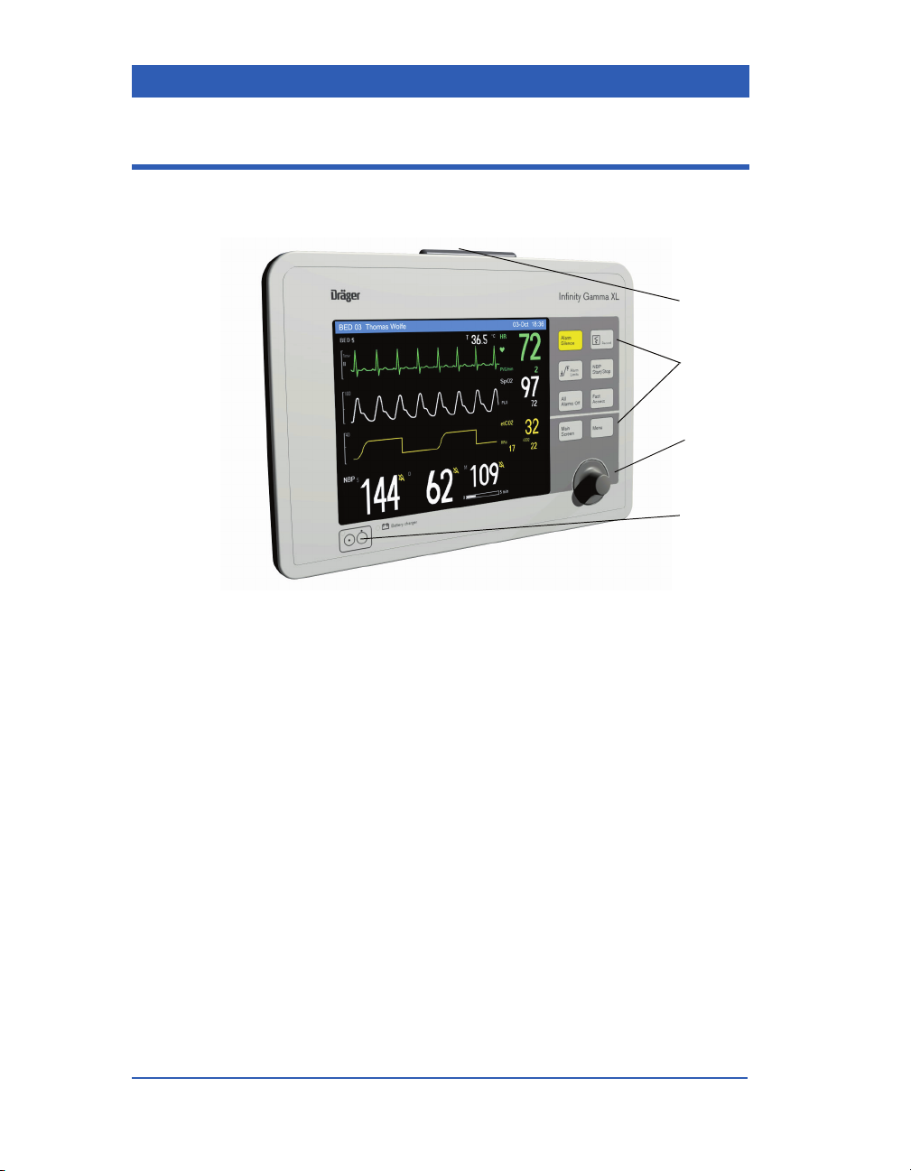
Front Panel
1
2
3
4
1) Alarm Light
2) Fixed Keys
3) Rotary Knob
4) Power ON/OFF Key
Page 1-10 Infinity Gamma Series VF4
Page 27
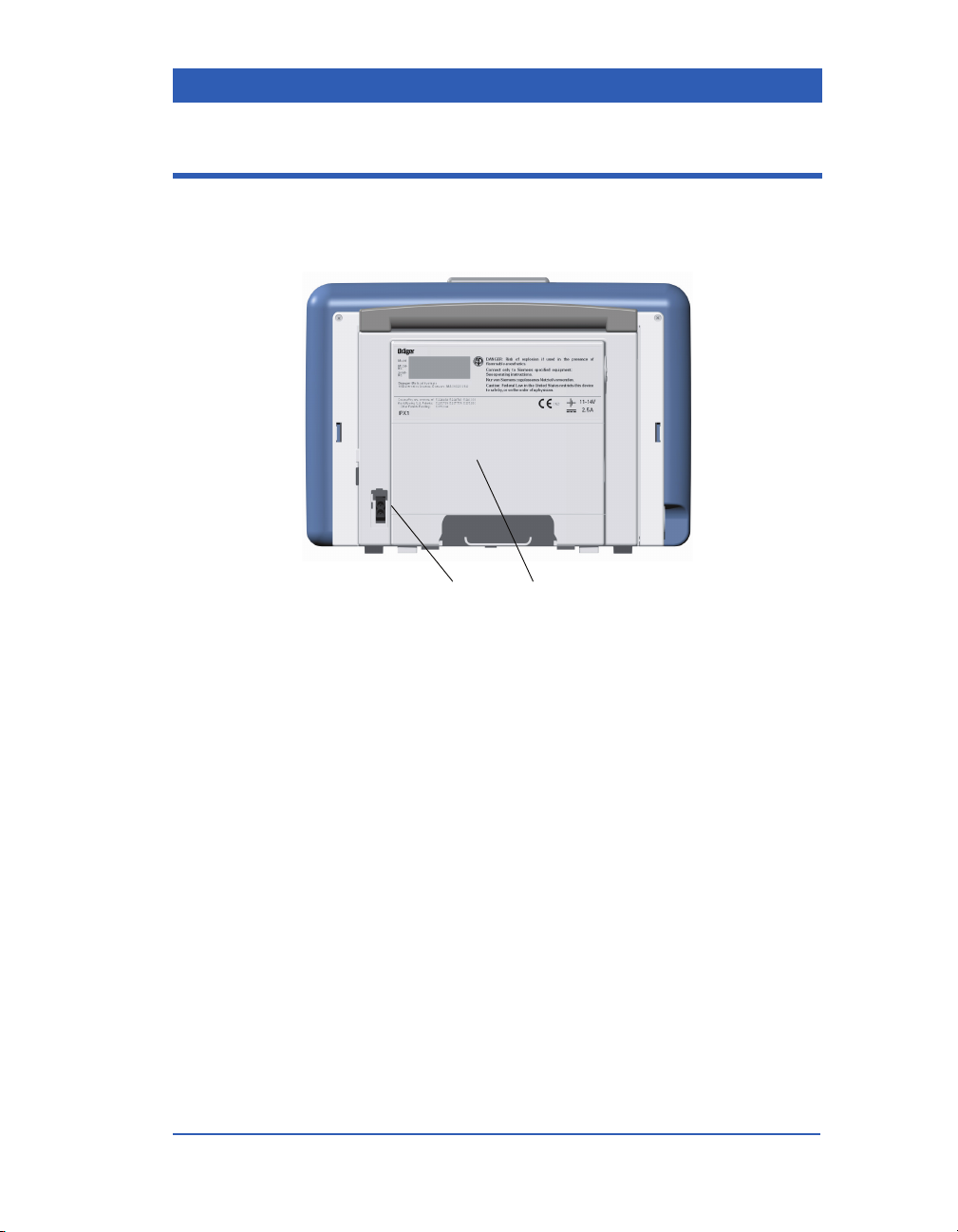
Back Panel
Overview
12
1) Power Supply Connection
2) Battery Compartment Cover
VF4 Infinity Gamma Series Page 1-11
Page 28
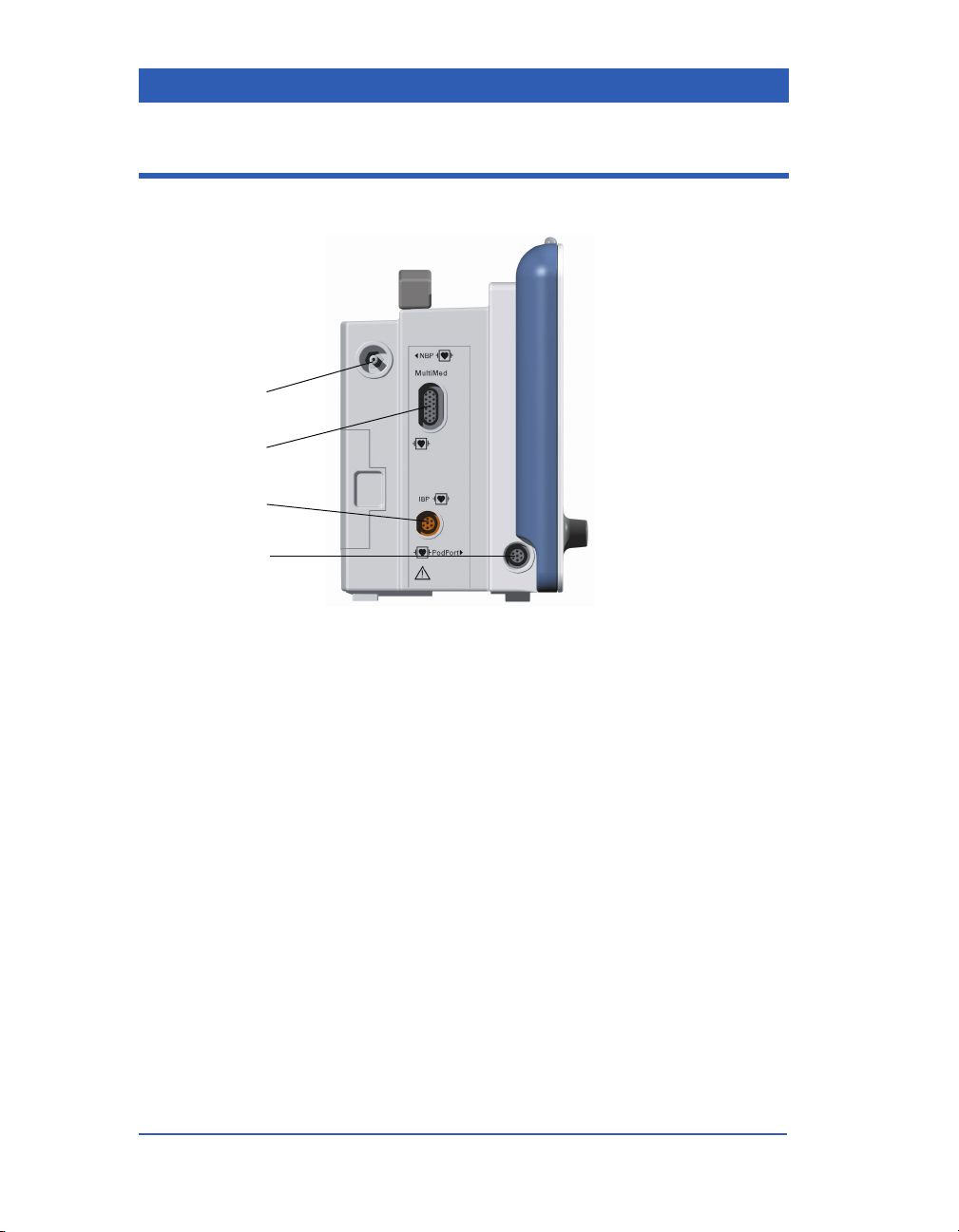
Left Side Panel
1
2
3
4
1) NBP Hose Connection
2) M
ULTIMED/NEOMED Connection
3) Invasive Blood Pressure Connection
4) PodPort (optional etCO
Page 1-12 Infinity Gamma Series VF4
Pod Connection)
2
Page 29
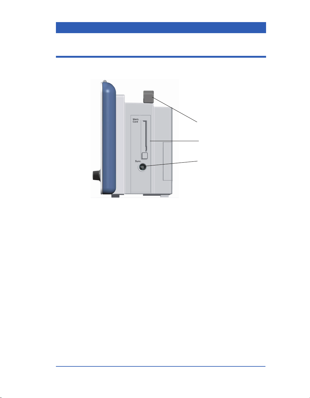
Right Side Panel
Overview
1
2
3
1) Carrying Handle
2) Memory Card Slot
3) QRS Sync. Output
VF4 Infinity Gamma Series Page 1-13
Page 30
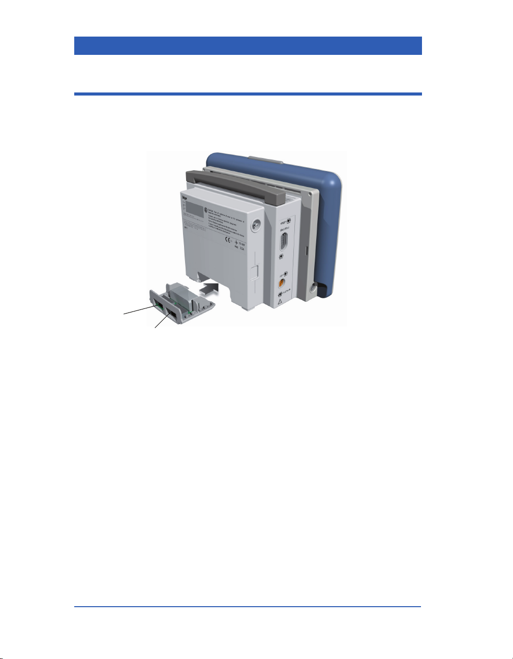
Interface Plate (optional)
1
2
1) X5: External VGA/Scio Multigas Module
2) X7: Alarm Output/R50 Recorder/RS232
Page 1-14 Infinity Gamma Series VF4
Page 31

Gamma/Gamma XL Display
Overview
Waveform
Channel 1
Waveform
Channel 2
Waveform
Channel 3
Waveform/
Parameter
Channel 4
NOTE: The fourth display channel is available as an option for the
Gamma monitor, but standard on all monitors Gamma XL. For
information on screen configuration, see the chapter Monitor Setup.
For information on the fourth channel option, please contact your
Dräger representative.
Alarm Colors
Colors are used to call your attention to important events:
! Black letters on a red background are used for life-threaten-
ing alarms and their messages (e.g., Asystole).
Message
Area
Parameter
Boxes
! Black letters on a yellow background are used for serious
alarms and their messages (e.g., Rsp Too High).
! Black letters on a white background are used for advisory
alarms and their messages (e.g., Rsp Lead Off).
! Amber letters on a dark gray background are used for net-
work messages (see the Network Applications chapter for
details).
! White letters on a blue background are used for messages and
information unrelated to the network (e.g., Battery
Charging).
VF4 Infinity Gamma Series Page 1-15
Page 32

Display Colors
The use of colors on the monitor allows you to identify a parameter and its waveform quickly. The following colors are predefined and cannot be changed:
Heart rate Green
PVC/ARR Green
ST Segment Analysis* Green
SpO
/PLS White
2
Respiration Blue
etCO2*, iCO2*, RRc* Yellow
Multigas Parameters O2-white, N2O-blue, ISO-pur-
ART, GP1, GP2* Red
PA Yel l ow
CVP, ICP Blue
*Options
ple, ENF-orange, HAL-red, DESblue, SEV-yellow
The parameter color extends to the following display elements:
! Parameter label.
! Parameter waveform.
! Parameter trend labels and graphs.
If the parameter box appears next to its waveform on the screen,
the values are also displayed in the appropriate parameter color.
Otherwise, the values are white.
Exceptions: For NBP and Temperature parameter and units, the
trend graph, trend label and parameter label are white, and no
waveform is available.
Page 1-16 Infinity Gamma Series VF4
Page 33

Rotary Knob
Using the rotary knob, you can:
! Select a screen area (parameter box or waveform field).
! Call up a menu and change menu options.
! Scroll through trend tables and graphs.
! Scroll through stored events.
! Switch between trend tables and graphs.
STEPS: Calling up a menu
1. Turn the knob clockwise or counterclockwise to navigate the
screen. Selected areas appear framed.
2. Press (click) the knob to call up a screen area’s menu (a
parameter menu or a waveform channel menu).
Overview
STEPS: Changing menu options
1. Dial to highlight the desired menu option.
2. Press the knob to activate the option.
3. Dial in the desired setting.
4. Press the knob to confirm the change.
5. To exit the menu, press the
VF4 Infinity Gamma Series Page 1-17
Main Screen fixed key.
Page 34

Fixed Keys
The monitor has a Power ON/OFF key and eight fixed keys on
the front of the unit. These keys give the user access to various
monitoring functions:
Power
Press this key to turn the monitor on or off.
Alarm Silence
Record
Alarm Limits
NBP Start/Stop
All Alarms Off
Fast Access
Menu
Main Screen
Press this key to silence an active alarm for
one minute.
Press this key to start a manual recording. If no
recorder is connected or assigned to this monitor, the recording is stored as an event and can
be viewed, printed or deleted at a later date.
Press this key to access the alarm limits table.
Press this key to start a manual NBP measurement, or to stop one in progress.
Press this key to silence all alarms for three
minutes.
Press this key to access the monitor’s Bottom
Channel menu as well tabular trends, graphical
trends, and the Event Recall screen.
Press this key to access the monitor’s Main
Menu.
Press this key to return to the monitor’s main
screen from any open menu or display, or to
return to monitoring after Standby or a patient
discharge.
Page 1-18 Infinity Gamma Series VF4
Page 35

Menus
Overview
Menus provide easy access to monitoring functions, including:
! Initial monitor and system setup.
! The setting of alarm functions.
! The setting of monitoring options for each parameter.
Menus are displayed in the waveform area. Use the rotary knob
or a fixed key to access menus. A complete menu tree is shown at
the end of this chapter.
NOTES:
! Some menu items are only available, if the corresponding mon-
itoring function has been enabled/selected (i.e. fourth waveform channel, second IBP parameter, full arrhythmia monitoring, ST monitoring, etCO
work monitoring).
! Parameter boxes for invasive blood pressure (IBP) show the
labels ART, PA, CVP, ICP or a generic pressure label (GP1 or
GP2); see the chapter Invasive Blood Pressure.
VF4 Infinity Gamma Series Page 1-19
monitoring, OCRG, wireless net-
2
Page 36

Power Sources
The monitor can be operated with battery power or connected to
line power via an AC adapter or Docking Station. See the chapter
Monitor Setup for a description of battery operation and the
AC adapter. See the chapter Network Applications for a description of the Docking Station and Pick-and-Go transport.
Monitor with Battery
Monitor with AC Adapter
Infinity Docking Station
Page 1-20 Infinity Gamma Series VF4
Page 37

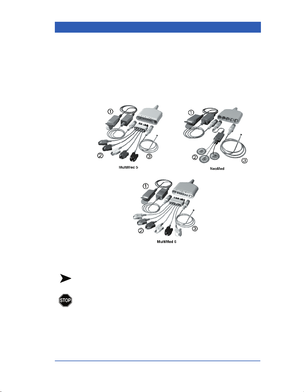
MULTIMED/NEOMED Pod
For easier cable management, ECG cable sets, the SpO2 sensor
and temperature probes are housed in a M
pod. See the Monitor Setup chapter for information on assembling the patient cables.
MULTIMED 5 Pod and Accessories
Overview
ULTIMED or NEOMED
MULTIMED 6 Pod and Accessories
NEOMED Pod and Accessories
VF4 Infinity Gamma Series Page 1-21
Page 38

etCO2 Pod and Multigas Module
An etCO2 pod for the measurement of end-tidal CO2, and a multigas module for the measurement of O
thetic agents are available as an option. See the chapters End-
Tidal CO
etCO2 Pod
and Multigas for more information.
2
, CO2, N2O and five anes-
2
Scio Multigas Module
Recorder
You can connect a Dräger R50 Series strip-chart recorder to the
monitor for the documentation of your patient’s vital sign information, including trends and alarms. For information on recordings, see the chapter Recordings.
R50 Recorder
Page 1-22 Infinity Gamma Series VF4
Page 39

Remote Displays
The bedside monitor can send data to a larger VGA video display
for an enhanced view of the monitoring functions. The VGA display connects directly to the Infinity Docking Station (IDS),
interface plate, or the Communication Power Supply (CPS). Use
of a Dräger-approved video display is recommended. For ordering information, see the Accessories appendix.
NOTE: The remote display output on the IDS/CPS is not galvanically isolated. If you use a video monitor other than the one
approved by Dräger, it must comply with IEC 60601-1. Upon
installation, the installer must ensure that in normal and single fault
conditions, the entire system meets the requirements of IEC 60601-1
and IEC 60601-1-1 (Medical Electrical Systems Standards). Refer
to the video monitor’s operating instructions to ensure that the
interconnection is within its intended use as specified by the manufacturer. Additionally, radiated and conducted emissions classification, suitability for flammable locations and water ingress
protection must be considered based on the intended use of the system.
Overview
VF4 Infinity Gamma Series Page 1-23
Page 40

Main Menu
Review Trend Graphs
Trend Tables
Event Recall
Admit/Discharge Patient Admit Patient Category Adult
Pediatric
Neonate
Name (dial in)
ID (dial in)
Admit Date (current date)
Care Unit (select)
Bed Label (select)
Discharge Discharge Patient? No
Yes
Transfer Care Unit (select)
Transfer Bed (select)
Start Transfer Confirm
Cancel
Copy Data Copy to Card
Name
ID
Start Transfer
Page 1-24 Infinity Gamma Series VF4
Page 41

Admit/Discharge Copy Data Copy to Monitor Name
ID
Start Transfer
Monitor Setup Main Screen Bottom Channel All
Waveform
Wave+NBP
NBP
OR Mode ON
OFF
Overview
Show Rsp/etCO
Screen Brightness Dim
Monitor Options Date & Time Date
Speaker Volume Low
Alarm Light ON
Trend Setup Channel 1 (select parameter)
Channel 2 (select parameter)
etCO
2
2
Rsp
Bright
Time
Medium
High
OFF
OFF
VF4 Infinity Gamma Series Page 1-25
Page 42

Monitor Setup Trend Setup Channel 3 (select parameter)
Recordings Primary Recorder (select)
Secondary Recorder (select)
Review Event Recall
Biomed (password)
Alarm Groups 1 - 255
Standby
Fast Access Menu
Bottom Channel All
Wavefo rm
Wave+N BP
NBP
Trend Graphs
Trend Tables
Event Recall
Channel Display Menu
(1, 2, 3, 4 Channel) Wavefo rm (select param.)
Size (param.specific)
Page 1-26 Infinity Gamma Series VF4
Page 43

Alarm Limits Table
(Parameter) Upper (dial in)
Autoset
Lower (dial in)
Alarm ON
OFF
Record Record
Store
Str/Rec
OFF
HR Menu
(HR P-Box) Tone Source ECG
Overview
SpO2
Tone Volume Low
Medium
High
OFF
Pacer Detect ON
OFF
QRS Mark ON
OFF
VF4 Infinity Gamma Series Page 1-27
Page 44

(HR P-box) Arrhythmia Setup Rate (dial in)
Count (dial in)
Alarm ON
OFF
Record Record
Store
Str/Rec
OFF
ECG Processing ECG1
ECG1&2
ECG Leads 3, 5, 6
Arrhythmia Basic
Full
OFF
Relearn (last relearn)
Page 1-28 Infinity Gamma Series VF4
Page 45

Rsp Menu
(Resp P-Box) Resp Mode Manual
Auto
OFF
Resp. Marker ON
OFF
Relearn (last relearn)
Apnea Time 10 . . . 30
OFF
Coincidence ON
OFF
Multigas Menu
Overview
(Agent P-Box) Agent Override Isoflurane
Enflurane
Halothane
Desflurane
Sevoflurane
OFF
Multigas Alarms (alarm table)
Autozero Delay
VF4 Infinity Gamma Series Page 1-29
Page 46

etCO2 Menu (with POD)
NOTE: If Scio rather than the pod is the etCO2 source, the etCO2 menu shows only
the selection RRc Apnea.
(etCO2 P-Box) etCO2 Source POD
SCIO
Averaging Breath
10s, 20s
Instant.
RRc Apnea 10 . . . 30
OFF
Sensor Cal.
Adapter Cal.
Balance Air
N2O/O2
>60% O2
Heliox
Meas. Mode Main
Side
Insp. Agent 0 . . . 20
Exp. Agent 0 . . . 20
Atm. Press. Mode Auto
Manual
Atm. Pressure 400 . . . 800
Page 1-30 Infinity Gamma Series VF4
Page 47

SpO2 Menu
(SpO2 P-Box) Tone Source ECG
SpO2
Tone Volume Low
Medium
High
OFF
Bar Graph ON
OFF
Averaging Normal
Fast
Sensor Type (informational only)
Overview
ST Menu
(ST P-Box) ISO (place point)
ST (place point)
Ref ON
OFF
Save (last save)
VF4 Infinity Gamma Series Page 1-31
Page 48

NBP Menu
(NBP P-Box) Interval Mode 2 . . . 240
OFF
Calibration Mode ON
OFF
Inflation Mode Adult: 270
Adult: 180
Ped: 180
Ped: 140
Neo: 140
Neo: 90
Measurement Tone ON
OFF
IBP Menu
(IBP P-Box) Label (select param.)
Zero
Cal. Factor 80 . . . 120
Mano. Cal. (mmHg)
1 . . . 300
Page 1-32 Infinity Gamma Series VF4
Page 49

2 Monitor Setup
Getting Started.......................................................................2-2
Using the AC Adapter ......................................................2-2
Using the Battery .............................................................2-4
Assembling MultiMed and NeoMed Pods ...................... 2-9
Starting the Monitor ............................................................2-10
Main Screen Configuration.................................................2-11
Waveform Selection.......................................................2-11
Bottom Channel Display................................................2-12
OR Mode .........................................................................2-15
Show Respiration or etCO2 Parameters......................2-16
Setting Date and Time.........................................................2-17
Setting the Master Speaker Volume ..................................2-18
Turning External Alarm Lights ON/OFF ............................ 2-19
Standby ................................................................................2-20
Saving Setups......................................................................2-21
Page 50

Getting Started
CAUTIONS:
! Before monitoring your patient, the battery that is delivered
with a new monitor has to be fully charged (see below).
! Before monitoring your patient, be sure you have read the
Important General Safety Considerations in the Overview
chapter.
Using the AC Adapter
The AC adapter connects the monitor to a hospital-grade power
outlet. It charges the battery during normal operation. In case of a
power failure, the monitor switches to battery power without loss
of monitoring data or settings.
WA RN I NG : Use only the AC adapter approved by
Dräger. Using a non-approved power supply could damage the monitor. Dräger assumes no liability for any
damage if you use a non-approved power supply.
Page 2-2 Infinity Gamma Series VF4
Page 51

Monitor Setup
STEPS: Connecting the AC Adapter
1. Connect the AC adapter's cable to the DC input on the monitor’s back panel.
2. Connect the power cord to the AC adapter.
3. Plug the other end of the power cord into a hospital-grade
outlet. The battery charge indicator on the front panel lights
up.
4. Press the
Power fixed key and wait until the display lights up
and the monitor completes its self-test.
If the monitor does not power on, verify the connections and
retry. If it fails again, take the unit out of operation and contact
DrägerService.
WA RN I NG : If the outlet or ground conductor is suspect, operate the monitor with a battery.
VF4 Infinity Gamma Series Page 2-3
Page 52

Using the Battery
The battery powers the monitor when the monitor is not connected to line power via the AC adapter, an IDS Docking Station,
or a CPS Communication Power Supply (IDS and CPS are
described in the chapter Network Applications). The battery fits
into the battery compartment at the back of the monitor.
There are two types of batteries: lead acid, or lithium ion (shown
below). Lead acid batteries provide 75 minutes of continuous
monitoring; lithium ion batteries provide 180 minutes of continuous monitoring.
Lead acid batteries can be installed or removed by the user. Lith-
ium ion batteries must be installed or removed by Dräger
personnel. The green battery gauge displayed at the bottom left
of the screen indicates the battery run time remaining for uninterrupted monitoring.
NOTE: The battery gauge appears only when you operate the
monitor on battery power.
When the battery charge is less than approximately 25%, the following happens:
! The battery gauge displays in yellow.
! The monitor emits an alert tone.
! The monitor displays the message Replace Battery Pack at
frequent intervals.
Page 2-4 Infinity Gamma Series VF4
Page 53

Monitor Setup
If the battery charge drops below 10 V, monitoring stops, but
monitoring settings, trended data, and stored recordings are saved
in memory.
Screen Brightness
To save power, the monitor’s display may automatically dim
when you change to battery operation.
With a lead acid battery, the display always dims on battery
power. With a lithium ion battery, you can choose whether or not
the displays dims.
The Brightness setting remains in effect through a power cycle.
Regardless of the setting, lithium ion batteries can power the
monitor for at least three hours, even if the display remains bright
during battery operation.
NOTES:
! The menu option Screen Brightness only appears when the
monitor is equipped with a lithium ion battery.
! This function is only supported with recent releases of the
micro-controller code. If the Screen Brightness option is not
available in the menu, although a lithium ion battery is
installed, an update of the micro-controller code is necessary
(contact your Dräger representative).
STEPS: Selecting the Screen Brightness
1. Press the Menu fixed key.
2. Click on
3. Click on
4. Click on
5. Select
VF4 Infinity Gamma Series Page 2-5
Monitor Setup.
Main Screen.
Screen Brightness.
Dim or Bright and click the knob.
Page 54

STEPS: Inserting a Lead Acid Battery into the
Monitor
NOTE: Before installing the battery, read the cautions and warnings in the Important General Safety Considerations section at the
beginning of this manual.
1. Turn the monitor so that its rear panel is facing towards you.
2. Press in on the tab in the right side of the battery compartment door and swing the door open until it lifts off the hinges
on the left side.
3. Insert the rechargeable battery in the compartment, electrical
terminals side first. The terminals of the battery must be
pushed into the clip in the left side of the battery compartment.
Page 2-6 Infinity Gamma Series VF4
Page 55

Monitor Setup
4. With the battery pushed into the left side of the battery com-
partment, press the right side of the battery into the clip at the
right side.
5. Insert the left side of the battery door into the hinges, and
swivel the door closed until the locking tab snaps into place.
6. Press the
Power fixed key to turn the monitor on. The green
light indicator in the key should light up.
7. Wait until the end of the self-tests and verify that the battery
gauge appears at the bottom of the display.
NOTE: The battery gauge appears only when you operate the
monitor on battery power.
To prolong battery life, we recommend the following:
! Use the AC adapter whenever possible.
! Keep the battery charged.
STEPS: Charging the Battery with the Monitor
The battery that is delivered with a new monitor needs to be fully
charged before monitoring. When connected to line power via the
AC Adapter, IDS, or CPS, the monitor automatically charges the
battery and the green Battery Charger LED lights up (the monitor
can be turned on or off).
To charge the battery:
1. Connect the monitor to line power and let the lead acid bat-
tery charge for 5½ hours, the lithium ion battery for 8 hours.
(The Battery Charging message appears intermittently.)
2. Wait until the battery is fully charged before monitoring a
patient. (The Battery Charging message no longer appears.)
NOTE: If the battery does not charge properly, the message Bat-
tery Charger Error appears. Contact your Biomedical technician to
replace the battery.
VF4 Infinity Gamma Series Page 2-7
Page 56

STEPS: Charging Lead Acid Batteries with a
Battery Charger
You can charge up to four additional lead acid batteries with the
battery charger available from Dräger. To do so:
1. Place the lead acid batteries on the
battery charger.
2. Keep the lead acid batteries in the
charger for at least four hours to
ensure a full charge.
WA RN I NG : Use the battery charger to charge lead acid
batteries only. Lithium ion batteries are not compatible
with the Dräger lead acid battery charger.
STEPS: Removing a Lead Acid Battery from the
Monitor
1. Connect the monitor to AC power or turn the monitor off.
NOTE: If the monitor is connected to AC power, monitoring can
continue while you replace the battery. If the monitor is not connected to AC power, turn the monitor off before removing the battery in order to assure a proper monitor shut-down.
2. Place the monitor on a flat surface.
3. Open the battery compartment door (back of the monitor).
4. Lift the battery from under the locking tab and pull the battery out.
WA RN I NG : To avoid explosion, do not disassemble, or
dispose of the battery in fire. Do not change the battery
in the presence of explosive hazards because of the possibility of sparks. If the monitor is not to be used for a
prolonged time, remove the battery from the battery
compartment.
Page 2-8 Infinity Gamma Series VF4
Page 57
Monitor Setup
Assembling MULTIMED and NEOMED Pods
Choose a 5-lead or 6-lead MULTIMED Pod (adult/pediatric applications) or a N
toring session. Assemble the pods as illustrated prior to connecting them to the monitor. (Parameter-specific patient preparation is
described in the individual parameter chapters.)
EOMED Pod (neonatal applications) for your moni-
1) SpO
VF4 Infinity Gamma Series Page 2-9
sensor 2) ECG lead sets 3) Temperature sensor
2
NOTE: The FiO2 and TEMP B connectors of the NEOMED™ pod
are not supported with the Gamma Series monitors.
WA RNI NG : Do not use the N
surgery. Use during cautery may result in burns to the
patient or clinical staff.
EOMED Pod during electro-
Page 58

Starting the Monitor
1. Press the Power fixed key. The green light indicator in the
key lights up.
2. Wait until the main screen appears at the end of the self-tests.
NOTES:
! If an internal failure or error should occur, the monitor’s screen
turns blank. If this should happen, turn the monitor off, then on
again. In case of persistent failure, remove the monitor from
service and call your Biomed technician.
! Do not use the monitor if you do not have an AC Adapter,
CPS, IDS, or a fully charged battery. Call your Biomed if you
are not familiar with the use of the battery or the power
adapter.
Page 2-10 Infinity Gamma Series VF4
Page 59

Main Screen Configuration
The monitor has four display channels. The top three channels
show waveforms and their corresponding parameter boxes. The
bottom channel can be configured to show either parameter
boxes, enlarged NBP values, a waveform, or a combination of a
waveform and parameter boxes (see illustrations below).
NOTES:
! A fourth display channel is standard for monitors Gamma XL
and available as an option for monitors Gamma. For information, contact your Dräger representative.
! Settings for screen brightness are explained under Using the
Battery, above.
Waveform Selection
STEPS: Selecting Parameters for Waveform
Channel Display
Monitor Setup
1. On the main screen, select a waveform channel with the
rotary knob and click the knob.
2. In the Channel Setup menu, click on
Waveform and select
the desired parameter or ECG lead for display. (For more
information, including the ECG cascaded display, see the
chapter ECG and Heart Rate.)
NOTE: If you change the monitor’s parameter display and the
M
ULTIVIEW WORKSTATION is storing waveforms selected manu-
ally (Auto Track OFF), you must also change the parameters at the
M
ULTIVIEW WORKSTATION. For more information, see the
M
ULTIVIEW WORKSTATION’s user guide.
VF4 Infinity Gamma Series Page 2-11
Page 60

Bottom Channel Display
STEPS: Selecting the Bottom Channel Display
1. Press the Menu fixed key.
2. Click on
3. Click on
4. Click on
NOTES:
! You can also call up the Bottom Channel menu by pressing the
! In OR mode, the monitor automatically displays gas values in
Monitor Setup.
Main Screen.
Bottom Channel.
Fast Access fixed key.
the bottom channel and the menu selection Bottom Channel is
not available.
5. Click on All, NBP, Waveform, or Wave+NBP to select one
of the following bottom channel displays:
Page 2-12 Infinity Gamma Series VF4
Page 61

Bottom Channel showing parameter boxes
Monitor Setup
Bottom Channel showing enlarged NBP values
VF4 Infinity Gamma Series Page 2-13
Page 62

Bottom Channel showing a fourth waveform
Bottom Channel showing a waveform and parameter boxes
Page 2-14 Infinity Gamma Series VF4
Page 63

OR Mode
Monitor Setup
The OR mode allows access to multigas monitoring functions and
is available for monitors Gamma XL operating in the adult or
pediatric mode.
STEPS: Selecting the OR Mode
1. Verify that the adult or pediatric patient category is selected.
2. Press the
3. Click on
4. Click on
5. Click on
6. Select
NOTE: Certain monitoring/display restrictions apply in the OR
mode. For more information, see the chapter Multigas.
Menu fixed key.
Monitor Setup.
Main Screen.
OR Mode.
ON and click the knob.
VF4 Infinity Gamma Series Page 2-15
Page 64

Show Respiration or etCO2 Parameters
STEPS: Selecting Rsp/etCO2
1. Press the Menu fixed key.
2. Click on
3. Click on
4. Click on
5. Select
NOTES:
! For more information on Respiration or etCO2 monitoring, see
! The Show Rsp/etCO2 menu option appears only if the etCO2,
Monitor Setup.
Main Screen.
Show Rsp/etCO
Rsp or etCO
the respective parameter chapters.
ST and IBP2 locked options are enabled.
2
.
2
and click the knob.
Page 2-16 Infinity Gamma Series VF4
Page 65

Setting Date and Time
Monitors operating in the Infinity network receive their date and
time settings from the network. For a stand-alone monitor, you
can set the current date and time as follows:
STEPS: Setting Date and Time
1. Press the Menu fixed key.
Monitor Setup
2. Click on
3. Click on
4. Click on
5. Click on
6. Click on the day, month, or year, dial in the desired setting
and click to confirm the new selection.
Monitor Setup.
Monitor Options.
Date & Time.
Date.
7. Click on
8. Click on the hour or the minutes, dial in the desired setting
and click to confirm the new selection.
VF4 Infinity Gamma Series Page 2-17
Time.
Page 66

Setting the Master Speaker Volume
The setting for the master speaker volume defines the volume for
alarm tones, pulse tones, attention and error tones. The available
settings are
NOTES:
! For safety reasons, you cannot turn the speaker volume off
! If your monitor is operating in the Infinity network and you
STEPS:Setting the Speaker Volume
1. Press the Menu fixed key.
Low, Medium, High, and OFF.
when the monitor operates as a stand-alone device or if the
French-NFC mode has been selected (a Service setting).
turn the speaker volume off, a crossed speaker symbol appears
above the first waveform channel.
2. Click on
3. Click on
4. Click on
Monitor Setup.
Monitor Options.
Speaker Volume.
5. Click the knob, select a setting, and click the knob again.
NOTE: The setting for the master speaker volume defines the
maximum volume for all tones, including the user-adjustable QRS
and SpO
ume to Low, but set the QRS and SpO
EKG or SpO
ume setting prevails and pulse tones sound at a low volume.
pulse tones. Therefore, if you set the master speaker vol-
2
menu (see EKG and SpO2 chapters), the master vol-
2
pulse tones to High in the
2
Page 2-18 Infinity Gamma Series VF4
Page 67

Monitor Setup
Turning External Alarm Lights ON/OFF
A set of alarm lights on top of the monitor blink red for lifethreatening alarms and yellow for serious alarms, if the external
alarm light function is enabled in the Monitor Setup menu
(default setting is ON). If more than one alarm occurs at the same
time, the lights blink for the alarm with the highest alarm grade. If
the user silences the alarm, the alarm lights remain lit without
flashing. If the user turns all alarms off, the alarm lights are
turned off as well.
STEPS: Turning External Alarm Lights On/Off
1. Press the Menu fixed key.
2. Click on
3. Click on
4. Click on
5. Select
WA RN I NG : The alarm light setting (ON/OFF) is not indicated on the screen. Before monitoring your patient, verify the alarm light setting in the Alarm Light menu.
NOTES:
! The external alarm lights do not flash for advisory alarms.
! During startup, the alarm lights blink briefly as part of the
Monitor Setup.
Monitor Options.
Alarm Light.
ON or OFF and click the knob again.
monitor’s functional check.
VF4 Infinity Gamma Series Page 2-19
Page 68

Standby
The standby function lets you interrupt and then resume monitoring. When you put the monitor into standby, all patient data and
monitoring setups are saved in memory until you resume monitoring. During standby, the monitor displays a Standby banner. If
the monitor is part of the Infinity network and its monitoring data
is displayed on the central station, the Standby banner appears
also on the central display.
STEPS:Placing the Monitor into Standby
1. Press the Menu fixed key.
2. Click on
Standby.
STEPS:Exiting Standby
1. To resume monitoring, press the
Main Screen fixed key. The New
Patient? prompt appears.
2. Select New Patient
resume monitoring the same patient.
Select New Patient
to start monitoring a new patient. If
admitting a new patient, the monitor
erases all previously stored patient
data (see the chapter Admission,
Transfer, Discharge).
NOTES:
! Upon startup, coming out of standby, or admitting a new
patient, alarms are disabled for 3 minutes or until you press the
All Alarms OFF fixed key.
! During standby, you can modify patient demographic data at
the central station at any time. The new data is transferred to
the monitor and available when monitoring resumes.
No, if you want to
Yes, if you want
Page 2-20 Infinity Gamma Series VF4
Page 69

Saving Setups
The current monitoring configuration can be saved and used
again. A saved configuration is specific to the selected patient
category and is automatically restored when a you admit a new
patient of the same category (e.g., pediatric).
The following monitoring settings are saved: waveform channel
assignments and scales, alarm limits and on/off status, NBP interval mode, IBP pressure labels, arrhythmia monitoring (adult or
pediatric mode only), respiration mode and markers, apnea time,
coincidence alarm, etCO
and detection, bottom channel display selection, recording selections (on/off/store), and trend setup.
NOTES:
! Saving setups is a password-protected function and can only be
performed by your Biomed.
! You cannot save a setup when an OCRG is displayed on the
screen. Exit the OCRG display before saving.
Monitor Setup
measurement mode, pacemaker setting
2
VF4 Infinity Gamma Series Page 2-21
Page 70

Page 2-22 Infinity Gamma Series VF4
Page 71

3 Network Applications
Overview.................................................................................3-2
Network Configurations........................................................3-3
Basic Network Components ...........................................3-4
Basic Bedside Setups......................................................3-5
Network Operation ................................................................3-6
Docking Station................................................................3-7
Docking and Undocking ..................................................3-9
Wireless Network Configuration...................................3-11
Wireless Network Operation ......................................... 3-13
Network Safety Considerations .........................................3-16
Alarm and Status Messages...............................................3-17
NOTES:
! The current software operates on the Dräger Infinity network,
but does not support the Dräger Sirenet network.
! To assure optimal network performance of your monitoring
system, make sure all network components operate at the
appropriate software level as disclosed in the Dräger compatibility chart. For more information, contact your technical personnel or your Dräger representative.
Page 72

Overview
The Infinity network provides communication links between the
bedside monitor and other network devices such as a central station, other monitors, recorders, and laser printers. The network
allows you to monitor your patient at a central location away
from the bedside, and to monitor many patients at once. In detail,
within the Infinity network you can:
! View patient data of up to 16 patients at a dedicated central
station (M
! Admit patients at the central station.
! Receive bedside alarm messages at the central station and at
other devices within the network.
! Receive alarm messages from other devices within the net-
work at the local bedside monitor.
! Control alarms from the central station.
! Initiate a Relearn of a patient’s ECG and respiration pattern
from the central station.
! Set arrhythmia parameters from the central station.
! Print recordings on network recorders and laser printers.
ULTIVIEW WORKSTATION™).
! Transfer patients between monitors in the network.
! Collect diagnostic logs at the central station.
! View monitoring data on a larger video display.
If the monitor becomes disconnected from the network, it operates in standalone mode and the M
ULTIVIEW WORKSTATION dis-
plays an offline message.
NOTE: In order to limit the number of alarm messages from
remote beds within the network, you can group beds into separate
alarm groups so that only messages from monitors within the same
group are shared. For details see the chapter Alarms and Messages.
Page 3-2 Infinity Gamma Series VF4
Page 73

Network Configurations
A basic Infinity network includes:
! Bedside monitors.
! A central station (MULTIVIEW WORKSTATION).
! Docking stations at the bedside.
! R50 Series recorders.
! Infinity network cabling and repeater hubs.
A basic Infinity wireless network includes:
! Bedside monitors.
! A central station (MULTIVIEW WORKSTATION).
! Wireless LAN PC Cards.
! Access points with antennae.
! R50 Series recorders.
! Infinity network cabling and repeater hubs.
Network Applications
Dräger offers a large variety of network components and supplies
that allow you to customize your hospital’s network configuration. Network setup and configuration are Service functions performed during installation. Please see your local Dräger
representative for details.
NOTE: A Care Unit is a group of beds with the same hospital-
assigned identification (i.e. CCU, ICU). The name of a Care Unit is
unique within the hospital. A Monitoring Unit is a logical group of
beds that share certain monitoring functions, such as alarm annunciations, recordings, and remote views. A Monitoring Unit can have
more than one central station and span more than one Care Unit.
VF4 Infinity Gamma Series Page 3-3
Page 74

Basic Network Components
Bedside Monitor
Simple Docking Station
(mount only)
Communication
Power Supply (CPS)
Central Station
IDS Power Supply
Interface Plate
Infinity Docking Station
(IDS)
R50 Recorder
Laser Printer
Access Points
Wireless LAN PC Card
Page 3-4 Infinity Gamma Series VF4
Page 75

Basic Bedside Setups
Network Applications
Access Point
Bedside Setup with IDS
Wireless Monitor with
Wireless LAN PC Card
Monitor with Interface Plate
Bedside Setup with CPS
VF4 Infinity Gamma Series Page 3-5
Page 76

Network Operation
The bedside monitor operates in network mode when it is:
! Docked at a docking station,
! Equipped with a wireless PC card in a wireless network
Docking stations must be configured for network mode (versus
standalone mode) by Dräger personnel during installation. Only
Dräger personnel can modify these configurations, which define
numerous network functions, including bedside labels, recorder
labels, and the availability of remote control functions of the bedside monitor from other network devices.
Wireless monitors must be admitted to the network during installation. Once admitted, the user can then select care unit and bed
label assignments according to where the wireless monitor is stationed (see the section Wireless Network Configuration, below).
While a wireless monitor is docked at a docking station, it automatically accepts the docking station’s care unit and bed label
assignments.
If central monitoring is enabled at the bedside, you can assign the
bedside to a display channel on the central station’s screen. The
monitor continuously sends the following information to the central station:
! Parameter values (including values reported as *** ).
! Waveforms and their scales.
! Current bedside alarm limits and settings.
! Alarms and status messages.
At the central station, you can also call up the bedside’s trend data
and diagnostic log and you can store monitoring events (see the
ULTIVIEW WORKSTATION User’s Guide).
M
Page 3-6 Infinity Gamma Series VF4
Page 77

NOTES:
! The only configurations of the IDS/CPS that you can perform
via the monitor’s menus are the assignment of alarm groups
and the selection of primary and secondary network recorders
(see the chapters Alarms and Messages and Recordings).
! If central monitoring is disabled at the IDS/CPS,
-- you cannot turn the monitor’s master speaker volume off,
-- no network offline messages appear at the bedside.
! If central monitoring is disabled at the IDS/CPS, you can con-
tinue to access the network recorder assigned to the IDS/CPS
and alarm messages continue to be broadcast between devices
in an alarm group.
! Configuration of the monitor’s network behavior is a pass-
word-protected Service function. For more information, consult with your biomedical personnel.
! If a network connection cannot be established upon powerup,
the monitor displays the message Incompatible CPS or Network Error.
Docking Station
Network Applications
The Infinity Docking Station (IDS) with companion DC power
supply powers the monitor and provides connections for optional
peripheral devices such as recorders, remote displays, or a nurse
call system. The docking station serves as a secure mount for the
monitor and allows quick mounting and dismounting in P
O transport situations.
G
ICK AND
While the monitor is docked at a docking station, its batteries are
being charged. In case of a power failure, the monitor switches
immediately to battery power without loss of data or monitoring
settings.
NOTE: The Infinity Docking Station (IDS), which offers full network connectivity and power, has replaced the simple Docking Station (mount only), which is used in conjunction with a Communication Power Supply (CPS). References to the simple Docking Station and CPS are included here for sites that still use them.
VF4 Infinity Gamma Series Page 3-7
Page 78

Multigas Module
External VGA/RS232 R50 Recorder
Infinity Docking Station (back panel)
Power Supply
Alarm Output
Infinity Network
ON/OFF switch
Power Cord
External VGA/RS232
Docking Station
Infinity Network
R50 Recorder
Alarm Output
Mount-only Docking Station and CPS (back panel)
Page 3-8 Infinity Gamma Series VF4
Page 79

Docking and Undocking
STEPS: Docking the Monitor
1. Hold the monitor firmly by its
handle and set it onto the Docking Station. Make sure the monitor is securely positioned and
clicks into place. The Docking
Station’s locking lever does not
move unless the monitor is
seated properly.
2. Slide the locking lever to the
right in order to engage the electrical connections and lock the monitor in place. The battery
charging indicator on the front of the monitor lights up.
CAUTION: To avoid dropping the monitor, do not let go of the
monitor’s handle until you have moved the locking lever as far to
the right as possible, thereby locking the monitor in place.
Network Applications
STEPS: Undocking the Monitor
1. Hold the monitor firmly by its handle. Slide the lever to the
left to disengage the power supply. (The monitor automatically switches to battery power.)
2. Continue to move the lever to the left until it clicks. Tilt the
monitor forward and lift it off the Docking Station.
When you remove the monitor from the Docking Station, patient
data and settings remain stored in the monitor's memory. The central station blanks the monitor’s data and displays the message
Bed Disconnected (unless a wireless card is inserted -- see the
section Wireless Network Configuration, below). Once the moni-
tor returns to its Docking Station, it resumes sending patient data
to the central station.
VF4 Infinity Gamma Series Page 3-9
Page 80

PICK AND GO versus Network Error
The network can distinguish between a network error and the
intentional removal of a bedside monitor from its Docking Station.
If the monitor loses its connection with the network due to a technical problem, the network generates a network error message.
When the monitor is removed from its Docking Station for transport, the central station displays a network status message (Bed
Disconnected).
If the bedside monitor’s speaker volume had been set to OFF during network operation, upon loss of communication with the network, it is automatically reset to 50% (default stand-alone level),
or to 100% in case of an active alarm (network error message).
Page 3-10 Infinity Gamma Series VF4
Page 81

Network Applications
Wireless Network Configuration
The Infinity Gamma Series monitor can operate in a wireless network which allows the monitor to establish and maintain contact
with the Infinity network and the central station without being
docked at a Docking Station.
A wireless monitor transmits and receives data with the help of a
wireless LAN PC card installed in the Memory Card slot on the
monitor’s side panel. The wireless card communicates with
access points which are strategically placed within a monitoring
unit in order to cover the desired transmission area.
MVWS
IDS
Bedside
Monitor
Wireless
Monitor
MVWS = MultiView WorkStation (central station)
IDS = Infinity Docking Station
AP = Access Point
AP IDS
Bedside
Monitor
If a wireless monitor loses contact with all access points and
wireless transmission is interrupted (i.e. you remove the wireless
card or the monitor is out of range), the network generates an
offline message and the monitor operates as a standalone device.
NOTE: For detailed information about installation and configuration of wireless components, refer to the Dräger publication
“Infinity Network Planning, Design, and Installation Handbook-Wireless Extensions Supplement.”
VF4 Infinity Gamma Series Page 3-11
Page 82

A wireless network offers the following:
! Seamless Patient Transport — A wireless monitor contin-
ues to communicate with the Infinity network during Pickand-Go transport situations and its data remains on the central display after leaving the bedside Docking Station.
! Seamless Patient Relocation — Patient and monitor can be
moved to a different room or care unit without ever losing
contact with the Infinity network.
! Simplified Network Setup — Wireless monitors can be net-
worked without the need of docking stations or hard-wired
hub connectors, which reduces the need for network cables
within the hospital. (Note: Central station, access points, and
recorders/printers are connected to the network by cable.)
WA RN IN G : Before operating the monitor in a wireless
network configuration, please read the Network Safety
Considerations at the end of this chapter.
STEPS: Installing the Wireless Card
1. Turn the monitor off.
2. Facing the monitor, turn the card so that the flat side (back
label) faces you.
3. Press the card firmly into the card slot until the slot’s release
button protrudes.
Card Slot
Release Button
To remove the card, turn the monitor off and press the release button.
Page 3-12 Infinity Gamma Series VF4
Page 83

Wireless Network Operation
Care Unit and Bed Label Assignments
A wireless monitor receives care unit and bed label assignments
in one of the following ways:
! Automatically when docking at a Docking Station.
! By manual entry via the Patient Admit menu.
When docking at a Docking Station, a wireless monitor automatically accepts the Docking Station’s Care Unit and Bed Label
assignments and communicates with the Infinity network via the
Docking Station. When the monitor undocks, wireless card and
access points take over communication between the monitor and
the network.
When operating in a network without docking stations, you enter
the Care Unit and Bed Label assignments in the Patient Admit
menu (see the following steps).
NOTE: Upon undocking, the monitor can either keep or give up
the bed label assignment it received from the Docking Station,
depending on the network setup performed by Service personnel
during installation.
Network Applications
! If the monitor has been configured to keep the Docking Sta-
tion’s bed label upon undocking, the monitor retains the bed
label as well as its display position at the central station.
! If the monitor has been configured to give up the Docking Sta-
tion’s bed label upon undocking, it either reverts back to a previously entered bed label, or the user must manually enter a
new care unit and bed label via the Patient Admit menu. If the
bed label entered is already in use, the monitor displays an
error message.
NOTE: After turning a wireless monitor on, it receives a list of
available care units and bed labels from the M
TION. If this list is not immediately available in the monitor’s
Patient Admit menu, wait until the list has been fully transmitted.
VF4 Infinity Gamma Series Page 3-13
ULTIVIEW WORKSTA-
Page 84

STEPS: Selecting Care Unit and Bed Label
1. Undock the monitor, if docked.
2. Press the
3. Click on
4. Click on
Menu fixed key.
Admit/Discharge.
Patient Admit.
5. Click on Care Unit.
6. Dial in the desired care unit from the list of available choices
and click the knob.
7. Click on
Bed Label.
8. Dial in the desired bed label from the list of available choices
and click the knob.
NOTES:
! You can enter a care unit and bed label only after undocking
the monitor. While the monitor is docked or operating as a
stand-alone device, these menu selections are not available.
! Upon undocking, wait a few moments until the monitor has
received a list of available care units from the network.
! Always select the care unit before selecting the bed label,
because the Bed Label menu only lists beds located in the
selected care unit.
! The overall list of available care units and bed labels is estab-
lished during network installation. If you cannot find the
desired care unit or bed label as a menu choice, contact your
Biomed or DrägerService.
Page 3-14 Infinity Gamma Series VF4
Page 85

Network Applications
Central Display
The central station identifies wireless monitors by a transmission icon on the central display. Upon undocking, the
bed’s central display channel (viewport) remains assigned to the
wireless monitor. If another monitor docks on the same Docking
Station which is still associated with the wireless monitor, the
new monitor receives the same bed label from the Docking Station, but does not replace the wireless monitor in the viewport of
the central station. In order to view the new monitor on the central display, the user has to assign a different display channel to
the new monitor via the central station’s Assign Bed menu.
NOTES:
! Patient name and ID continuously identify the patient on cen-
tral displays, recordings, and data bases, whether the monitor is
in transport or docked.
! If a wireless monitor is transmitting to a central station but has
not been assigned a viewport at that station, the message Not
monitored by central appears in the monitor’s message area.
Patient Relocation
You can move monitor and patient to a different room and care
unit by simply docking the monitor at the new location. Alternatively you can select care unit and bed label of the intended new
location via the Patient Admit menu (see the section Selecting
Care Unit and Bed Label).
During transport, the wireless monitor continues to communicate
with its assigned central station via the access points. Upon docking at the new location, the monitor accepts the new Docking Station’s care unit and bed label assignments as well as its display
position on the central station’s cluster screen.
If you change central stations, that is, move the monitor to a
room that is monitored by a different central station, the original
central station blanks the monitor’s data and displays the message
Bed Disconnected.
NOTE: During the transition between wireless and wired network
operation, the network may generate an error tone, if the transition
takes more than a few seconds. There is no loss of data and normal
network operation continues, as soon as the M
S
TATION has recognized the monitor’s new connection status.
VF4 Infinity Gamma Series Page 3-15
ULTIVIEW WORK-
Page 86

Network Safety Considerations
When operating the monitor in a wireless network, please observe
the following:
! Before using the wireless monitoring equipment, read the
instructions and safety warnings supplied by the wireless
equipment manufacturer.
! While the unit is transmitting or receiving signals, do not
hold the transmitting/receiving unit close to exposed body
parts, especially the face or eyes. The antenna/wireless card
should be at least 2" (5 cm) away from the body.
! Operation of the wireless network relies on uninterrupted sig-
nal transmission between the transmitting and receiving components of the network. When using the wireless network, be
aware that
-- certain structural limitations within the hospital building
may interfere with signal transmission,
-- other devices emitting radio frequencies, such as leaky
microwave ovens or warmers, may interfere with signal
transmission,
-- the frequencies emitted by the device may interfere with
the operation of other wireless operated medical equipment.
! The installation of wireless equipment must be performed by
qualified Service technicians. Any changes or modifications
to the equipment not expressly approved by the equipment
manufacturer may result in equipment malfunction or damage.
! In order to isolate the Dräger wireless Infinity network from
other 802.11b operators within the hospital, the SSID of each
set of access points has to be unique. Access points are not
considered medical equipment and should be kept out of the
patient’s vicinity. For further information, consult the manufacturer’s documentation or the Dräger publication
“Infinity
Network Planning, Design, and Installation Handbook-Wireless Extensions Supplement.
Page 3-16 Infinity Gamma Series VF4
”
Page 87

Network Applications
Alarm and Status Messages
When the monitor is connected to the network, network messages alert you of
network operating conditions. Some messages display only once (i.e., Remote
Limit Change), while others appear alternately until the condition has been
resolved (i.e. alarm messages such as BED 200:ECG Leads Off). A network
alarm error creates an error tone, while status messages do not.
Screen Message Condition
Selected Bed Label Currently in Use
Duplicate Address Another network device has been programmed with a
Incompatible CPS The monitor is connected to a SIRENET CPS, not an
Network Alarm Error An interruption in the network communication has been
Not Monitored by Central A wireless monitor is transmitting to a central station, but
Offline The monitor is not connected to the network or the net-
Remote Limit Change Alarm settings (on/off, alarm limits, alarm recording,
A wireless monitor undocks, but its assigned bed label is
already in use.
The user selects a care unit and bed label for a wireless
monitor, but the bed label is already in use.
conflicting identification. The bedside monitor is treated
as being offline.
Infinity IDS/CPS.
The monitor is connected to an Infinity IDS/CPS, but the
software is incompatible. Call your service support.
detected while an alarm is active; the speaker volume at
the bedside has been increased to its maximum level.
is not assigned a viewport on the central station’s cluster
screen.
work is not configured correctly.
A wireless monitor has traveled out of range.
The wireless card is not installed properly.
including ARR and ST) have been changed at the M
VIEW WORKSTATION.
ULTI-
Remote Relearn Relearning of the patient’s ECG or respiration pattern
Silence by Remote Alarm has been silenced at the M
has been initiated at the M
TION.
ULTIVIEW WORKSTATION.
ULTIVIEW WORKSTA-
VF4 Infinity Gamma Series Page 3-17
Page 88

Page 3-18 Infinity Gamma Series VF4
Page 89

4 Admission/Discharge/
Transfer
Overview.................................................................................4-2
Patient Admission .................................................................4-3
Admit Menu.......................................................................4-4
Patient Category...............................................................4-5
Name and ID .....................................................................4-6
Admit Date ........................................................................4-8
Patient Discharge .................................................................. 4-9
Data Transfer .......................................................................4-10
Transfer Across the Network ........................................4-11
Transfer with a Data Memory PC Card.........................4-13
Page 90

Overview
The Patient Admit menu allows you to enter and edit a patient’s
personal data (name, ID, admit date) and select the patient category. If your monitor is operating in a monitoring network, you
can also review or change the monitor’s care unit and bed label
assignments.
In network mode, you can admit patients at the bedside monitor
or at the central station. The central station offers more data entry
fields (such as birth date, height, weight) which the Infinity
Gamma Series monitor does not display but which can be
reviewed or edited at the central station (see the user’s guide to
the M
You can transfer patient data and monitoring setups between
monitors over the Infinity network or with the help of a data card.
If you discharge a patient, the monitor deletes the patient’s monitoring data.
ULTIVIEW WORKSTATION).
Page 4-2 Infinity Gamma Series VF4
Page 91

Admission/Discharge/Transfer
Patient Admission
When you turn on the monitor or exit the standby mode, the monitor displays a New Patient? prompt to assure that previously
stored patient data is deleted before you monitor a new patient.
To start monitoring a new patient, press the rotary knob and click
on
New Patient? YES. The monitor deletes all previously stored
monitoring data, including trends, events, and recordings.
To continue monitoring a previous patient, press the rotary knob
and click on
stored monitoring data.
New Patient? NO. The monitor retains previously
NOTE: After a power-cycle or upon leaving standby, all alarms
are turned off for three minutes or until you press the All Alarms
Off fixed key.
VF4 Infinity Gamma Series Page 4-3
Page 92

Admit Menu
STEPS: Calling up the Patient Admit Menu
1. Press the Menu fixed key.
2. Click on
3. Click on
NOTE: You cannot enter selections for Care Unit and Bed Label
when the monitor is docked at a Docking Station or operating as a
stand-alone device. For information on selecting the care unit and
bed label, see the chapter Network Applications.
Admit/Discharge.
Patient Admit.
Page 4-4 Infinity Gamma Series VF4
Page 93

Patient Category
NOTE: The currently selected patient category is indicated
between the first and second waveform channels next to the parameter boxes.
STEPS: Selecting the Patient Category
1. Call up the Patient Admit menu (Menu > Admit/Discharge >
Patient Admit, see above).
Admission/Discharge/Transfer
2. Click on
Patient Category.
3. Dial in the desired patient category (Adult, Pediatric, Neonate) and click the knob.
When you change the patient category, the monitor:
! Clears all current alarms, including their messages.
! Stops any NBP measurement in progress.
! Deletes stored trend data, events, and recordings.
! Returns alarm limits to their category-specific default settings
(see appendix Default Settings and Biomedical Support).
! Returns waveform display scales (sizes) to their category-
specific default settings (see appendix Default Settings and
Biomedical Support).
! Sets the display range for trend values according to the
selected patient category (see Trends chapter).
VF4 Infinity Gamma Series Page 4-5
Page 94

When switching to the neonatal mode, the monitor also:
! Disables arrhythmia detection and clears all arrhythmia labels
from the screen.
! Disables pacemaker detection.
! Disables ST Segment analysis (if option is available).
! Allows viewing of an Oxy-Cardiorespirogram (if option is
available).
Name and ID
STEPS: Entering Name and ID
1. Call up the Patient Admit menu (Menu > Admit/Discharge >
Patient Admit, see above).
2. Click on
Name. A white entry field appears for the first char-
acter of the name.
3. Click the knob, dial in the first
character (A-Z, a-z, 0-9) and click
the knob again.
4. Turn the knob clockwise to scroll to the next entry field and
click. Dial in the second character and click. If you need to
separate words (i.e. first name from last name), click on a
blank space.
Page 4-6 Infinity Gamma Series VF4
Page 95

Admission/Discharge/Transfer
5. Enter the remaining characters accordingly.
The Admit Menu can display up
to 9 characters at a time, but you
can enter additional characters
(up to 25 for the name and up to 12 for the ID) by scrolling
past the up arrow ( ↑ ) at the end of the line, thereby shifting
the entry to the left. Once entered, the full name does appear
in the name field above the top waveform channel, on central
station displays, and on recordings.
To make changes to your entry,
you can dial in and click on the
left or right arrow ( ← and → ).
Clicking on the left arrow deletes the character and moves the
entry one space to the left; clicking on the right arrow moves
the character and the entry one space to the right.
6. To exit the name entry line, click
on the up arrow ( ↑ ).
7. Enter the patient ID accordingly.
VF4 Infinity Gamma Series Page 4-7
Page 96

Admit Date
STEPS: Entering the Admit Date
1. Call up the Patient Admit menu (Menu > Admit/Discharge >
Patient Admit, see above).
2. Click on
current date.
3. If necessary, edit the date by clicking on the day, month, or
year entry fields and dialing in the desired date.
4. To exit the date entry line, simply scroll off to the left or
right.
Admit Date. The monitor automatically enters the
Page 4-8 Infinity Gamma Series VF4
Page 97

Admission/Discharge/Transfer
Patient Discharge
You can discharge a patient only at the bedside, not at the central
station. Upon discharge, the monitor deletes all previously stored
monitoring data (such as QRS reference complexes, trends,
events, and recordings), and it returns to default or previously
stored monitoring settings (see the chapter Default Settings and
Biomedical Support).
STEPS: Discharging a Patient
1. Press the Menu fixed key.
2. Click on
3. Click on
4. Click on
When you discharge a patient at the bedside, the central station
deletes the bedside’s data from the bed view and displays a Dis-
charge banner for this bed.
NOTE: You can also discharge a patient from the New Patient?
prompt upon leaving the Standby mode. In this case, however, the
patient’s name remains displayed at the central station until you
admit a new patient.
Admit/Discharge.
Discharge.
Discharge Patient? YES.
VF4 Infinity Gamma Series Page 4-9
Page 98

Data Transfer
You can transfer patient data between monitors in the following
ways:
! By sending data to a different monitor over the Infinity net-
work.
! By copying data onto a memory card and then loading it into
a different monitor (stand-alone option).
The transfer of patient data involves a source monitor and a destination monitor. The source monitor is the unit from which the
data is transferred. The destination monitor is the unit receiving
the data. Transferred patient data includes the patient’s name, ID,
admit date, patient category, as well as stored trends.
NOTES:
! When a data transfer takes place between two monitors whose
selected units of measure do not match (i.e.°C/°F, mmHg/kPa,
mm/mV), the destination monitor adopts the units of measure
that were selected at the source monitor.
! When a data transfer takes place between two monitors with
different enabled software options, the destination monitor
accepts data only for those options which are enabled at the
destination monitor (i.e. ST, etCO
! If the Respiration or the etCO
source monitor, but the same waveform is not selected for display at the destination monitor (see selection Show Rsp/Show
etCO
eter cannot be accepted by the destination monitor. To transfer
this data, first select the desired waveform display (Rsp or
etCO
! For data transfer between Gamma Series monitors, lead V+
will be transferred only if both the source and the destination
monitors are using a 6-lead ECG cable. Use of a smaller lead
set cable will only transfer data corresponding to the smaller
lead set. The remaining data will be lost.
! Stored events cannot be transferred.
), and ignores the rest.
2
waveform was displayed at the
2
in the Respiration chapter), then the data for this param-
2
) at the destination monitor.
2
Page 4-10 Infinity Gamma Series VF4
Page 99

Admission/Discharge/Transfer
Transfer Across the Network
NOTE: Before data transfer can take place over the network, the
source monitor must be placed into Standby mode.
STEPS: Transfer Across the Network
At the source monitor:
1. Place the source monitor into Standby.
At the destination monitor:
1. Press the
2. Click on
3. Click on
4. Click on
Menu fixed key.
Admit/Discharge.
Transfer. The Transfer menu opens.
Care Unit. Selection *** is the default and automat-
ically selects all care units. If you want to narrow your search
for the transfer bed and select the specific care unit in which
the source monitor is located, dial in the appropriate care unit
from the available choices in the menu and click the knob.
NOTE: The menu shows only those care units which have at least
one bedside monitor in Standby mode.
5. Click on Transfer Bed.
6. Select the bed label of the source monitor and click the knob.
VF4 Infinity Gamma Series Page 4-11
Page 100

NOTES:
! The Transfer Bed menu displays all networked beds in the
selected care unit that are currently in Standby mode.
! You must click on a bed label, even if there is only one avail-
able bed listed in the transfer menu; if you do not select a bed,
the transfer cannot take place.
! If a previous patient had not been discharged at the destination
monitor before data transfer, the discharge takes place automatically during transfer and all previous patient data is deleted.
7. Click on Start Transfer.
8. Click on
Confirm to start the transfer.
During transfer, the Transfer menu displays the status message
Transferring data. Once the transfer is complete, the patient is
automatically discharged from the source monitor and admitted
to the destination monitor.
If the transfer is interrupted or unsuccessful, the destination monitor displays a transfer error message. In this case, the source
monitor retains its data and you can attempt the transfer again.
Page 4-12 Infinity Gamma Series VF4
 Loading...