

Page 1

Titus
Tragbares Anästhesiegerät
Portable Anaesthetic Machine
Gebrauchsanweisung
Instructions for Use
1-131-95
Page 2

Inhalt
Contents
Inhalt
Seite
Zu Ihrer und Ihrer Patienten Sicherheit.......................3
Hinweise für den Umgang mit Sauerstoff-
und Druckgasflaschen...................................................4
Zweckbestimmung...................................................... 5
Monitoring....................................................................6
Modellbeschreibung.................................................... 7
Titus aufrüsten........................................................... 10
Gasversorgung............................................................10
Kreissystem aufbauen..................................................13
Messung des exspiratorischen Atemvolumens............. 13
Schlauchverbindungen herstellen.................................14
Ventilog mit Druckgas versorgen..................................15
Kombination mit Ventilog 2...........................................16
Kombination mit Ventilog 3...........................................17
Vapor aufsetzen...........................................................18
Überwachungen.......................................................... 19
Anästhesiegas-Fortleitungssystem (AGS) montieren.... 22
Manuelle Beatmungsvorrichtung.................................. 23
Potentialausgleich........................................................23
Für den Notfalleinsatz.................................................. 24
Contents
Page
For Your Safety and that of Your Patients...................3
Recommendations on handling oxygen and
compressed-gas cylinders.............................................4
Intended Use................................................................5
Monitoring....................................................................6
Description of Models..................................................7
Assembling Titus........................................................10
Gas supply..................................................................10
Assembling the circle system.......................................13
Measuring the expiratory minute volume.......................13
Connecting hoses....................................................... 14
Compressed gas supply for Ventilog............................15
Combination with Ventilog 2........................................ 16
Combination with Ventilog 3........................................ 17
Fitting Vapor................................................................18
Monitoring................................................................... 19
Connecting to anaesthetic gas scavenging system.......22
Manual ventilation bag................................................. 23
Equipotential bonding.................................................. 23
For emergency use only...............................................24
Titus NMR für den Einsatz in der
Kernspintomographie................................................ 25
Geräte-Check.............................................................31
Checkliste.................................................................. 32
Betrieb........................................................................37
Frischgasversorgung................................................... 37
Betriebsarten...............................................................39
Notfalleinsatz............................................................... 41
Gebrauchsdauer überwachen......................................42
Maßnahmen bei Gasausfall..........................................42
Zusätzliche Hinweise................................................... 43
Betriebsende...............................................................44
Pflege......................................................................... 45
Gerät abrüsten............................................................ 45
Magill-Inhalationseinrichtung........................................ 45
Pflegeliste für Anästhesiegerät Titus.............................46
Reinigung und Desinfektion......................................... 50
Sterilisation..................................................................51
Wartungs-/Instandhaltungsintervalle.............................51
Betriebsbereitschaft prüfen.......................................52
Anhang....................................................................... 58
Funktionsschema.........................................................58
Sicherheitseinrichtungen..............................................61
Technische Daten........................................................63
Titus MRI for Use
with MRI..................................................................... 25
Equipment Check.......................................................31
Checklist.................................................................... 34
Operation................................................................... 37
Fresh gas supply......................................................... 37
Operating modes.........................................................39
For emergency use only...............................................41
Checking use.............................................................. 42
What to do if gas supply fails....................................... 42
Additional instructions..................................................43
End of use...................................................................44
Care............................................................................45
Stripping down machine.............................................. 45
Magill inhalation device................................................ 45
Care list for Titus anaesthetic apparatus...................... 48
Cleaning and disinfection.............................................50
Sterilisation..................................................................51
Service/Maintenance intervals......................................51
Testing Readiness for Operation............................... 52
Appendix.................................................................... 58
Functional Diagrams....................................................58
Safety Features........................................................... 61
Technical Data.............................................................63
2
Page 3

For Your Safety and that of Your PatientsZu Ihrer und Ihrer Patienten Sicherheit
Zu Ihrer und Ihrer Patienten
Sicherheit
Gebrauchsanweisung beachten
Jede Handhabung an dem Gerät setzt die genaue Kenntnis und Beachtung dieser Gebrauchsanweisung voraus.
Das Gerät ist nur für die beschriebene Verwendung bestimmt.
Instandhaltung
Das Gerät muß halbjährlich Inspektionen1) und Wartungen1) durch Fachleute unterzogen werden (mit Protokoll).
Instandsetzungen1) am Gerät nur durch Fachleute. Für
den Abschluß eines Servicevertrags sowie für Instandsetzungen empfehlen wir den DrägerService. Bei
Instandhaltung1) nur Original-Dräger-Teile verwenden.
Kapitel “lnstandhaltungsintervalle“ beachten.
Zubehör
For Your Safety and that of Your
Patients
Strictly follow the Instructions for Use
Any use of the apparatus requires full understanding and
strict observance of these instructions. The apparatus is
only to be used for purposes specified here.
Maintenance
The apparatus must be inspected1) and serviced1) by
experts at regular 6 month intervals (and a record kept).
Repairs1) and general overhaul of the device may only be
carried out by experts. We recommend that you take out
a service contract with DrägerService and ensure that all
repairs are carried out by them. Only original Dräger
parts must be used for maintenance1). Observe the
chapter on "Maintenance Intervals".
Accessories
Nur das in der Zubehörliste aufgeführte Zubehör verwenden.
Only use the equipment itemized on the list of accessories.
1)
Inspektion = Feststellen des Ist-Zustandes
Wartung = Maßnahmen zur Bewahrung des Soll-Zustandes
Instandsetzung = Maßnahmen zur Wiederherstellung des Soll-
Zustandes
Instandhaltung = Inspektion, Wartung, ggf. Instandsetzung
1)
Inspection = examination of actual condition
Service = measures to maintain specified condition
Repair = measures to restore specified condition
Maintenance = inspection, service and, if applicable, repair
3
Page 4

Zu Ihrer und Ihrer Patienten Sicherheit
Hinweise für den Umgang mit Sauerstoff- und Druckgasflaschen
For Your Safety and that of Your Patients
Recommendations on handling oxygen and compressed-gas
cylinders
Kopplung mit elektrischen Geräten
Elektrische Kopplung mit Geräten, die nicht in dieser Gebrauchsanweisung erwähnt sind, nur nach Rückfrage bei
den Herstellern oder einem Sachverständigen.
Haftung für Funktion bzw. Schäden
Die Haftung für die Funktion des Gerätes geht in jedem
Fall auf den Eigentümer oder Betreiber über, soweit das
Gerät von Personen, die nicht dem DrägerService angehören, unsachgemäß gewartet oder instandgesetzt wird
oder wenn eine Handhabung erfolgt, die nicht der bestimmungsgemäßen Verwendung entspricht.
Für Schäden, die durch die Nichtbeachtung der vorstehenden Hinweise eintreten, haftet Dräger nicht.
Gewährleistungs- und Haftungsbedingungen der Verkaufs- und Lieferbedingungen von Dräger werden durch
vorstehende Hinweise nicht erweitert.
Dräger Medical AG & Co. KGaA
Safe connection with other electrical equipment
Electrical connections to equipment which is not listed in
these book should only be made following consultations
with the respective manufacturers or an expert.
Liability for proper function or damage
The liability for the proper function of the apparatus is
irrevocably transferred to the owner or operator to the
extent that the apparatus is serviced or repaired by
personnel not employed or authorised by DrägerService
or if the apparatus is used in a manner not conforming to
its intended use.
Dräger cannot be held responsible for damage caused
by non-compliance with the recommendation given
above.
The warranty and liability provisions of the terms of sale
and delivery of Dräger are likewise not modified by the
recommendations given above.
Dräger Medical AG & Co. KGaA
Hinweise für den Umgang mit Sauerstoffund Druckgasflaschen
● Flaschenventile an Sauerstoff-Flaschen und Druckmin-
derer für Sauerstoff nicht ölen oder fetten und nicht mit
fettigen Fingern berühren.
Explosionsgefahr!
● Sauerstoff-Flaschen nicht zusammen mit leicht
entzündbaren Stoffen lagern.
● Gefüllte Flaschen vor direkter Wärmeeinwirkung
schützen (keine Lagerung im Bereich direkter Sonneneinstrahlung oder in unmittelbarer Nähe eines Heizkörpers).
● Ventilhandräder nur mit der Hand bedienen. Keine
Werkzeuge benutzen. Flaschenventile sind Präzisionsteile, die durch Gewaltanwendung leicht beschädigt
werden.
● Undichte und schwergängige Flaschenventile fachge-
recht reparieren lassen.
Recommendations on handling oxygen and
compressed-gas cylinders
● Oxygen cylinder valves and oxygen pressure reducers
must not be oiled or greased, or touched with oily
fingers.
Danger of explosion!
● Do not store oxygen cylinders with substances which
ignite easily.
● Protect filled cylinders from direct sources of heat (do
not store in direct sunlight or close to a radiator).
● Valve handwheels should only be operated manually.
Do not use tools. Cylinder valves are precision
components which can easily be damaged when force
is applied.
● Leaking or stiff cylinder valves should be repaired by
trained personnel.
4
Page 5

Intended UseZweckbestimmung
Zweckbestimmung
lnhalationsanästhesiegerät mit kontinuierlichem
Frischgasflow. Frischgasdosierung über einen
Meßröhrenblock für O2 und N2O (optional: zusätzlich Air
(Luft)) und über einen Anästhesiemittelverdunster.
Für den mobilen Einsatz während der Ersten Hilfe am
Unfallort*) und während des Transports (Gasversorgung
aus einem tragbaren Flaschenpaket) sowie für den Einsatz in medizinisch genutzten Räumen, wie Arztpraxen
und Kliniken; in diesem Fall Gasversorgung normalerweise aus einem zentralen Versorgungssystem (ZV).
Versorgung aus 3- bzw. 11-Liter-Flaschen (O2 und N2O)
möglich, wenn Titus auf einem entsprechend ausgerüsteten Fahrgestell plaziert ist.
Als spezielle Gerätevariante kann Titus in der Kernspintomographie eingesetzt werden (s. ab Seite 25 »Titus NMR«).
Titus ist mit Kreissystem 9 oder mit halboffenem Narkosesystem wie z. B. Magill-lnhalationseinrichtung
ausrüstbar.
Optional:
Rüstsatz »Set Kinderkreissystem ISO« für Kleinkinder.
Intended Use
lnhalation anaesthetic machine with continuous fresh gas
flow. Fresh gas flow via a flowmeter block for O2 and
N2O (optional: also for air) and via an anaesthetic
vaporiser.
The machine is intended for mobile use for First Aid at
the scene of an accident*) and during transport (gas
supply from a portable cylinder pack) as well as for use
in medical environments, such as surgeries and hospitals;
in these situations, gas is normally supplied from a
pipeline system (PS). Supply is possible from 3-litre or
11-litre cylinders (O2 and N2O) if Titus is placed on a
specially equipped trolley.
In a specific version, Titus can be used in magnetic
resonance imaging (see page 25 »Titus MRI«).
Titus can be fitted with the ISO circle system 9 or a semiopen anaesthetic system or alternatively a Magill
inhalation device.
Optional:
ISO Infant Circle System for small children.
Hinweise zum Gebrauch
Es dürfen nur nichtentflammbare Narkosemittel
nach EN 740 verwendet werden! Brandgefahr!
Da dieses Gerät nicht für den Gebrauch mit entflammbaren Anästhesiemitteln, (Äther, Cyclopropan etc.) zugelassen ist, ist die Verwendung von antistatischen (leitfähigen) Atemschläuchen und Gesichtsmasken nicht erforderlich.
Leitfähige Atemschläuche und Gesichtsmasken können
bei Hochfrequenz-Chirurgie Verbrennungen verursachen
und werden in diesem Fall für dieses Gerät nicht
empfohlen.
Zusätzliche elektrische Geräte, die auf der Oberseite aufgeklinkt werden, müssen über eine
Potentialausgleichsleitung mit dem Grundgerät
verbunden werden!
Das Gerät unter Aufsicht von qualifiziertem medizinischen
Personal benutzen, um im Falle einer Fehlfunktion umgehend Abhilfe zu schaffen!
*) Für Einsatzfälle am Unfallort nur Geräte mit fest angeschlossenem
Narkosemittelverdunster verwenden (s. Vapor-Festanschluß, S. 9)
Instructions for use
Only not inflammable anaesthetic agents may be
used according to EN 740! Danger of fire!
As this machine is not licensed for the use of inflammable
anaesthetic agents (ether, cyclopropane or similar
agents), the use of antistatic (conductive) respiratory
tubes and face masks is not necessary.
Conductive respiratory tubes and face masks can cause
burns at high-frequency surgery and in this case are not
recommended for this machine.
Additional electrical appliances that are latched
onto the top, have to be connected to the main
machine by means of a potential compensation
line.
Use the machine only under supervision of qualified
medical personnel in order to react immediately and
appropriately in case of malfunction.
*) At the scene of an accident, only machines with a fixed anaesthetic
vaporiser may be used (see Fixed Vapor p. 9)
5
Page 6

Monitoring
Monitoring
Monitoring
Die Europanorm (EN 740)* fordert für AnästhesieArbeitsplätze Überwachungs- und Alarmeinrichtungen
zum Schutz gegen gefährliche Ausgangszustände:
– Atemwegsdruckmessung mit oberer Alarmgrenze
(untere Alarmgrenze empfohlen)
– exspiratorische Atemvolumenmessung (untere Alarm-
grenze empfohlen)
– inspiratorische Sauerstoffkonzentration mit unterer
Alarmgrenze
– Narkosemittelkonzentrationsmessung mit unterer und
oberer Alarmgrenze
– CO
– Diskonnektion- und Stenoseüberwachung bei Verwen-
Diese Einrichtungen sind nicht Bestandteil des Titus und
müssen durch geeignete Zusatzgeräte bereitgestellt
werden. Die entsprechenden Schnittstellen sind in den
technischen Daten beschrieben. Wird der Titus als
Notfallgerät eingesetzt, gelten die obigen Forderungen
nur als Empfehlung.
Titus mit integrierter Druckluft-Zusatzeinrichtung darf aus
Sicherheitsgründen nur mit inspiratorischer O2-Messung
eingesetzt werden.
Werden Überwachungsgeräte eingesetzt, muß der Anwender nachprüfen, ob diese Geräte den gesetzlichen
Bestimmungen entsprechen und ob sie die vom NarkoseBeatmungsgerät gelieferten Leistungen zuverlässig überwachen können.
-Konzentrationsmessung mit unterer und oberer
2
Alarmgrenze
dung eines automatischen Beatmungsgerätes
Monitoring
For anaesthetic workstations, the European Standard
(EN 740)* requires monitoring and alarm in order to
protect against dangerous initial conditions:
- airway pressure measuring with alarm upper limit
(alarm lower limit is recommended).
- expiratory tidal volume measuring (alarm lower limit is
recommended).
- inspiratory oxygen concentration with alarm lower and
upper limit.
- measuring of the concentration of anaesthetic agents
with alarm lower and upper limit.
-CO2 concentration measuring with alarm lower and
upper limit.
- checking of disconnection and stenosis in case of
automatic ventilation.
These facilities are not part of the Titus. Therefore
adequate additional appliances have to be provided.
Relevant interfaces are described in the technical data. Is
the Titus deployed as a First Aid unit, the requirements
above are only recommendations.
For reason of safety, Titus with integrated auxiliary
compressed-air unit must be used with an inspiratory
O2 monitor.
If monitoring equipment is used, the user must check that
the equipment conforms to legal requirements, and
reliably monitors the efficiency of the anaesthetic
ventilator.
*) Anästhesie-Arbeitsplätze und ihre Module
– Besondere Festlegungen –
6
*) Anaesthetic workstations and their modules
– particular requirements –
Page 7

Description of ModelsModellbeschreibung
Modellbeschreibung
Die Grundgeräte
Alle Ausrüstungsmerkmale in Klammern ( ) gehören nicht zur Grundausrüstung; Lieferung nur auf besondere
Bestellung.
– Tragbares Narkosegerät, zum An-
hängen an eine Wandschiene, an
ein Patientenbett oder an ein
(Fahrgestell).
– Anschlüsse für die Versorgung mit
Druckgasen O2, N2O (und Air) aus
einem zentralen Versorgungssystem – ZV – (oder aus Druckgasflaschen).
– Meßröhrenblock für die Dosierung
von O2 und N2O (und Air).
N2O
(Air)
Description of Models
Basic Units
Items of equipment in brackets ( ) are
not part of the basic equipment and
are supplied only on special order.
– Portable anaesthetic machine to be
O
2
hooked on a wall rail on the
patient's bed or on a (trolley).
– Connections for supplying
compressed gases O2, N2O (and
Air) from a pipeline system – PS –
(or from gas cylinders).
– Flowmeter block for measuring
flow of O2 and N2O (and Air).
Auf besondere Bestellung
– Fahrgestell ohne Halterungen oder
mit Halterungen für zwei 3- bzw.
11-Liter-Flaschen O2 und N2O.
Flaschen, Druckminderer und Anschlußschläuche separat bestellen.
Auf die obere Platte des Fahrgestells können Monitore aufgeklinkt
werden. Aufklinken des Beatmungsgerätes mit Extra-Basisplatte.
– Titus-Air mit zusätzlichem Anschluß
für Druckluft (s. Bild oben).
– Nur O2- und N2O-Versorgung aus
Flaschen möglich – nicht Air. Für
Versorgung aus Flaschen sind andere Anschlußschläuche erforderlich als für die Versorgung aus
einer ZV.
– Air und N2O sind nur alternativ do-
sierbar- über ein- und dieselbe
Meßröhre (siehe auch Diagramm
auf Seite 59). Wahl des Gases
N2O oder Air durch manuelles
Umschalten am Schalter unter dem
Dosierventil.
N2O
O2
On special order
– Trolley without holders or with
holders for two 3 or 11-litre O2 and
N2O cylinders. Cylinders, pressure
reducers and connecting hoses
must be ordered separately.
Monitors may be mounted on the
upper shelf of the trolley. The
ventilator can be mounted with an
(Air)
N
O
O
2
2
additional baseplate.
– Titus-Air with additional probe for
compressed air (see top picture).
– Only O2 and N2O can be supplied
from cylinders – not Air. Different
connecting hoses are required for
a supply from cylinders than for a
supply from a pipeline system (PS).
– Air and N2O can only be dosed
alternately via one and the same
flowmeter tube (see also the
diagram on page 60). N2O or Air is
selected manually using the switch
below the flow valve.
7
Page 8

Modellbeschreibung
Description of Models
Folgende Grundgeräte werden
The following basic models are available.
angeboten.
Titus Low-Flow Vapor-Stecksystem mit S-ORC M 33 041 Plug-in Vapor with S-ORC
Titus Standard Vapor-Stecksystem mit S-ORC M 33 042 Plug-in Vapor with S-ORC
Titus Standard Vapor-Festanschluß mit S-ORC M 33 043 Fixed Vapor with S-ORC
Titus Standard* Vapor-Stecksystem ohne S-ORC* M 33 044 Plug-in Vapor without S-ORC*
Titus Standard* Vapor-Festanschluß ohne S-ORC* M 33 045 Fixed Vapor without S-ORC*
Titus NMR Vapor-Stecksystem mit S-ORC M 33 046 Plug-in Vapor with S-ORC
Titus Asia** Vapor-Stecksystem mit S-ORC M 32 947 Plug-in Vapor with S-ORC
Titus Asia** Vapor-Festanschluß mit S-ORC M 32 948 Fixed Vapor with S-ORC
Titus NMR Asia** Vapor-Stecksystem mit S-ORC M 33 058 Plug-in Vapor with S-ORC
Geräte ohne ORC dürfen nur in Ländern eingesetzt
werden, in denen ORC nicht gesetzlich vorgeschrieben
ist. Diese Geräte tragen nicht das CE-Zeichen.
Beschreibung der Sicherheitseinrichtungen:
–O2 -Mangelsignal (in allen Grundgeräten)
– S-ORC und
–N2O-Sperre
im Abschnitt »Sicherheitseinrichtungen« Seite 61.
*) Im Geltungsbereich der Europanorm nicht zugelassen.
Machines without ORC may only be used in countries
where ORC is not a legal requirement. This machines are
not designed with the CE-Label.
Description of safety features:
–O2 shortage signal (in all basic units)
– S-ORC and
–N2O cut-off
see Appendix, page 61 »Safety Features«.
*) In the area of validity of the European Standard not licensed.
**) Diese Geräte besitzen abweichend von der Europanorm länder-
spezifische Farbmarkierungen und seitenverkehrt positionierte
Meßröhren für N2O und O2. Kein Verkauf innerhalb des europäischen Wirtschaftsraumes.
8
**) Contrary to the European Standard, these machines have national
colour codes and flowmeter tubes, which are positioned the other
way round. No sale within the European economic area.
Page 9

Description of ModelsModellbeschreibung
Kurzbeschreibung
1 Vapor-Stecksystem:
Der Anästhesiemittelverdunster
Dräger-Vapor * kann mit einem
Hebel entriegelt und vom Anästhesiegerät abgenommen werden.
Damit ist ein schneller Wechsel
von Anästhesiemitteln möglich.
Titus mit Vapor-Stecksystem
nicht für den mobilen Einsatz
(z. B. Erste Hilfe am Unfallort)
benutzen!
2 Vapor-Festanschluß:
Der Vapor ist fest am Anästhesiegerät angeschraubt. Wechsel nur
durch DrägerService möglich.
Titus mit Vapor-Festanschluß ist für
den mobilen Einsatz am Unfallort
geeignet.
Brief description
1 Plug-in Vapor:
The Dräger-Vapor * anaesthetic
vaporiser can be unlocked with a
lever and detached from the
anaesthetic machine. This enables
1
a quick change-over to a different
anaesthetic agent.
Titus with plug-in Vapor must not
be used for mobile applications
(such as First Aid at emergency)!
2 Fixed Vapor:
The Vapor is fixed to the
anaesthetic machine, and can only
be changed by DrägerService.
2
Titus with a fixed Vapor is suitable
for mobile use at emergency.
3Sensitive Oxygen Ratio Controller
S-ORC:
Flow-abhängiges Steuerelement
für eine Mindest-O2-Konzentration
(21 Vol.% O2) im Frischgas.
Geräte mit S-ORC sind mit einem
Aufkleber »S-ORC« am Gerät gekennzeichnet.
*) Hierbei handelt es sich entweder um
einen Vapor 19.n oder um einen Vapor
2000, im folgenden nur Vapor genannt.
Devapor ist nicht einsetzbar!
Achtung: Bei Verwendung eines Vapor
2000 ist darauf zu achten, daß der Titus
entsprechend umgerüstet worden ist.
Merkmal der Umrüstung: Die Gummitülle
im Aufhängebereich des Vapor schließt
bündig mit der Gehäuseoberfläche ab.
3
S-ORC
3Sensitive Oxygen Ratio Controller
S-ORC:
Flow-dependent control to maintain
a minimum O2 concentration
(21 vol.%) in the fresh gas.
Machines with S-ORC are marked
with an »S-ORC« label on the
machine.
*) In this case it is either a Vapor 19.n or a
Vapor 2000, in following only called as
Vapor.
Attention: Using a Vapor 2000, the Titus
has to be modified accordingly.
Modification: The rubber nozzle behind
the Vapor must be replaced with a thin
one. So that the Vapor can stand vertically.
9
Page 10
Titus aufrüsten
Gasversorgung
Assembling Titus
Gas supply
Titus aufrüsten
Gerät nicht übermäßig kippen!
Beim Vapor 19.n treten bis zu einem Kippwinkel von 45°
keine Konzentrationsabweichungen auf (bei Vapor 2000
bis 30°).
Für einen Transport, bei dem der Kippwinkel größer als
45° ist, muß das Anästhesiemittel aus dem Vapor abge-
lassen werden (gilt nur für Vapor 19.n). Gebrauchsanweisung Vapor beachten!
Bei schief stehendem Anästhesiegerät kann der
Meßfehler der Durchflußmeßröhren größer sein als unter
»Technische Daten« spezifiziert.
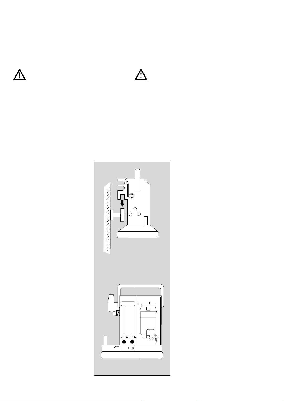
Zum Aufrüsten Gerät entweder
● an eine Wandschiene hängen
oder
● auf eine ebene, horizontale Unter-
lage (Tisch oder Fahrwagen)
stellen
oder
● in die Aufnahme des speziellen
Titus-Fahrgestells einhängen.
Assembling Titus
The machine must not be tilted excessively!
The Vapor 19.n may be tilted as far as 45° without any
deviation in concentration (until 30° at Vapor 2000).
During transport, when the Vapor may be tilted by more
than 45°, it must be emptied of anaesthetic agent (only
for Vapor 19.n). Adhere strictly to the instructions for use
of the Vapor.
If the anaesthetic machine is placed on a sloping surface,
the flowmeter may show greater variation than is
specified under »Technical Data«.
To assemble, either
● hook the machine onto a wall rail
or
● place it on a level, horizontal base
(table or trolley)
(Air)
O
N
O
2
2
or
● hook it over the oval-shaped rail
on the special Titus trolley.
Gasversorgung
Die in Klammern ( ) gesetzten Hinweise auf »Air« gelten nur, wenn das
Narkosegerät mit Air als Drittgas versorgt werden soll.
Dies ist nur möglich, wenn Titus mit
dem entsprechenden Druckgasanschluß ausgerüstet ist.
● Beide Dosierventile schließen.
10
Gas supply
The recommendations for »Air« given
in brackets ( ) apply only if the
anaesthetic machine has been
supplied for air as a third gas.
This is only possible if Titus is fitted
with the appropriate compressed gas
connection.
● Close both flow control valves.
Page 11

Titus aufrüsten
Gasversorgung
Assembling Titus
Gas supply
Versorgung aus einer zentralen
Versorgungsanlage (ZV)
● Schläuche in die Anschlüsse für
die Druckgase O2 und N2O
schrauben.
● (Schlauch auf den Druckgasan-
schluß »Air« am Titus schrauben).
● Die Stecker der Schläuche in die
Wandentnahmeventile der ZV
stecken.
Gasversorgung O2 und N2O aus
Flaschen
● Die 11-Liter-Flaschen mit
Flaschenmantel bzw. die 3-LiterFlaschen in die Halterungen des
Fahrgestells stellen und mit den
Lederriemen festschnallen.
● Druckminderer an die Flaschen-
ventile schrauben.
● Schlauchverbindungen zwischen
Druckminderern und Gaseingängen am Titus herstellen.
N2O
O2
Supply from a pipeline
system (PS)
● Screw hoses onto the connectors
for O2 and N2O.
(Air)
N
O
O
2
2
● (Screw hose onto the air
connector on Titus – male thread
on Titus.)
● Connect the probes on the hoses
to the wall terminal units of the
pipeline system.
O2 and N2O supplies from
cylinders
● Place the 11-litre cylinders
complete with cylinder jackets or
the 3-litre cylinders in the holders
(Air)
N
O
O
2
2
on the trolley and secure with
leather straps.
● Screw pressure reducers to
cylinder valves.
● Connect hoses between pressure
reducers and gas inlets on Titus.
11
Page 12

Titus aufrüsten
Gasversorgung
Assembling Titus
Gas supply
Gasversorgung O2 und N2O aus
tragbarem Flaschenpaket
für die Versorgung im mobilen Einsatz und die Notversorgung im Klinikbetrieb.
Das tragbare Flaschenpaket – ca.
10 kg – enthält je eine 2-Liter-Flasche O2 und N2O. Das Flaschenpaket kann an eine Wandschiene oder
ein Bett angehängt oder auf den
Boden gestellt werden.
● Gasversorgung zum Narkose-
gerät herstellen – entweder
a) über Schläuche mit ZV-Stecker
oder
b) über Schläuche mit Gewinde für
Druckminderer. In diesem Fall die
ZV-Steckkupplungen vom Flaschenpaket abschrauben.
O2 and N2O supplies from portable
cylinder pack
for supply during mobile use
and as an emergency supply in
hospitals.
The portable cylinder pack – about
(Air)
N2O
O
b
2
10 kg – contains one 2-litre cylinder
each of O2 and N2O.
The cylinder pack can be hooked
onto a wall rail or onto a bed, or
placed on the floor.
a
● Supply gas to anaesthetic
machine – either
a) via hoses with probes for the
pipeline system
or
b) via hoses with threaded con-
nectors for pressure reducers. In
this case, unscrew the terminal
units from the cylinder pack.
12
Page 13

Titus aufrüsten
max. 134
Kreissystem aufbauen
Messung des exspiratorischen
Atemminutenvolumens
Assembling Titus
Assembling the Circle System
Measurement of expiratory minute volume
Kreissystem aufbauen
● Komponenten nach zugehöriger
Gebrauchsanweisung »Kreissystem 9« vorbereiten und zusammenbauen.
● Kreissystemträger auf Zapfen am
Narkosegerät stecken und mit
Rändelschraube sichern.
1CO2-Absorber mit frischem
Atemkalk (Drägersorb 800)
füllen und in den Aufnahmekonus
des Kreissystemträgers stecken.
2 Inspirationsventil in den Auf-
nahmekonus des CO2-Absorbers
stecken, Tülle nach links drehen.
Nur außerhalb des Geltungsbereichs der Europanorm oder für
den mobilen Notfalleinsatz:
● Atemwegsdruckmesser an das
Kreissystem anschrauben.
Assembling the Circle
System
● Prepare and assemble compo-
nents following »ISO Circle
max. 134
°C
5
10
30
50
70
2
1
max. 134°C
5
10
30
50
70
System 9 Instructions for Use«.
● Fit circle system arm over pin on
anaesthetic machine, and secure
with knurled screw.
1 Fill CO2 absorber with fresh soda
lime (Drägersorb 800) and fit to
the input cone on the circle
system arm.
2 Fit inspiratory valve to the input
cone on the CO2 absorber; turn
nozzle to the left.
For emergency mobile use:
● Connect airway pressure gauge
to the circle system.
Messung des exspiratorischen
Atemminutenvolumens
Mit PM 8050 oder alternativ mit dem
PM 8060 oder Minuten-Volumeter.
max. 134°C
5
10
30
50
70
Measurement of expiratory
minute volume
With PM 8050 or alternatively
with the PM 8060 or Minute
Volumeter.
3 Minuten-Volumeter auf das Kreis-
system aufschrauben.
Alternativ:
4 Sensorgehäuse mit Flow-Sensor
für Patientenmonitor PM 8050/
8060 aufschrauben (siehe
Gebrauchsanweisung "Patientenmonitor PM8050/8060").
5 Exspirationsventil auf das
Minuten-Volumeter aufschrauben.
Alternativ: auf das Sensorgehäuse.
4
5
max. 134°C
5
10
30
50
70
3
3 Connect Minute Volumeter to the
circle system.
Alternatively:
4 Screw on the sensor housing with
flow sensor for patient monitor
PM 8050/8060 (see Instructions
for Use "Patient Monitor
PM 8050/8060").
5 Connect expiratory valve to
Minute Volumeter.
Alternatively: to sensor housing.
13
Page 14

Titus aufrüsten
Schlauchverbindungen herstellen
Assembling Titus
Connecting hoses
Schlauchverbindungen
herstellen
Je einen Atemschlauch auf
1 lnspirationsventil und
2 Exspirationsventil stecken
und mit
3 Y-Stück verbinden.
Y-Stück mit der für den Patienten
notwendigen
4 Maske oder einem Katheteran-
schlußstutzen ausrüsten.
Optional:
● Mikrobenfilter am Inspirationsven-
til bzw. am Exspirationsventil einsetzen.
Gebrauchsanweisung »Mikrobenfilter« beachten.
Connecting hoses
1
4
3
2
max. 134°C
5
10
30
50
70
max. 134°C
5
10
30
50
70
Fit one breathing hose each to
1 inspiratory valve and
2 expiratory valve
and connect to
3 Y-piece.
Fit
4 mask or catheter connector to
Y-piece, depending on the
patient's needs.
Optional:
● Use microbial filter on inspiratory
or expiratory valve.
Follow »Microbial Filter
Instructions for Use«.
5 Atembeutel mit
6 Verbindungstülle und
7 Atemschlauch anschließen,
wenn kein automatisches Beatmungsgerät vorhanden ist.
Sonst: s. Seite 16.
8 Frischgasschlauch am Narkose-
gerät und am Kreissystemträger
anschrauben.
5 Connect breathing bag to
6 connector and
7 breathing hose when no
automatic ventilator is in use.
max. 134°C
5
10
30
50
70
Otherwise: see page 16.
8 Fit fresh gas hose to anaesthetic
machine and to circle system arm.
5
7
6
8
14
Page 15

Titus aufrüsten
Ventilog mit Druckgas versorgen
Assembling Titus
Compressed gas supply for Ventilog
Ventilog mit Druckgas
versorgen
Beatmungsgerät neben Titus plazieren, vorzugsweise auf einer Konsole,
die an derselben Wandschiene
befestigt ist wie Titus.
Andere Möglichkeiten:
● Titus auf Fahrgestell:
auf separate Klinkplatte des Fahrgestells.
● Separates Fahrgestell mit Klink-
platte.
● Tischplatte.
Ventilog nicht oberhalb von
elektrisch betriebenen
Geräten – z. B. auf Monitor
plazieren. Brandgefahr durch
Austreten von Sauerstoff
oder sauerstoffangereicherter
Luft! Die umgekehrte Anordnung ist erlaubt.
Compressed gas supply for
Ventilog
Place ventilator beside Titus,
preferably on a bracket mounted on
the same wall rail as Titus.
Other options:
● Titus on trolley:
on separate latching plate of the
trolley.
● Separate trolley with latching
plate.
● Work surface.
Ventilog must not be placed
above electrically-operated
machines – for instance on a
monitor. Danger of fire from
the emitted pure oxygen or
oxygen-enriched air. The
reverse arrangement is
permitted.
Druckluft-Verteiler oder SauerstoffVerteiler mit entsprechendem Anschlußschlauch für Versorgung aus
ZV verwenden.
● ZV-Versorgung – Air steht zur
Verfügung – Titus ist zusätzlich
mit Air-Anschluß ausgerüstet.
● ZV-Versorgung – nur O
steht zur
2
Verfügung – Titus ist nicht mit AirAnschluß ausgerüstet (oder AirAnschluß bleibt frei).
ZV
ZV
Air
O
2
Air-Anschluß
Titus
Air
Anschluß
Ventilog
O
-Anschluß
2
Titus
O
2
Anschluß
Ventilog
(5±0,5bar)
(5±0,5bar)
(500±50)kPa
(500±50)kPa
With a supply from the pipeline system
use a medical air distributor or oxygen
distributor with suitable connecting
Air
Air
Air
Air/O
2
Air/O
2
Air/O
2
2
O
2
O
Air
Air/O
2
Air/O
2
Air/O
2
hose.
● PS-supply – Air as a third gas is
available – Titus is additionally
fitted with an air-connector.
● PS-supply – only O
is available –
2
Titus is not fitted with an air
connector (or air-connector
remains open).
15
Page 16

Titus aufrüsten
max. 134°C
Kombination mit Ventilog 2
Assembling Titus
Combination with Ventilog 2
Kombination mit Ventilog 2
Ventilog 2 mit Kreissystem 9
verbinden
Gebrauchsanweisung für Ventilog 2
beachten!
1 Pneumatisches Umschaltventil am
Kreissystemträger anschrauben –
2 Atemschlauch 1,1 m am Ventilog 2
und am Umschaltventil
anschließen –
3 Steuerleitung anschließen – Tülle
Frontseite Ventilog 2 und Tülle
Rückseite Umschaltventil –
4 Frischgasschlauch anschließen –
5 Atembeutel mit Atemschlauch an
das Umschaltventil anschließen –
Atembeutel anhängen.
Combination with Ventilog 2
Connecting Ventilog 2 with
Circle System 9
Follow the Ventilog 2 Instructions for
max. 134°C
5
10
30
50
70
Use!
1 Screw the pneumatic changeover
1
valve to circle system arm –
2 Connect the 1.1 m breathing
5
4
hose to the Ventilog 2 anaesthetic
ventilator and connect to the
changeover valve –
2
3 Connect the control line – one
3
nozzle to the front panel of the
Ventilog 2 anaesthetic ventilator
and the other to the rear of the
changeover valve –
4 Connect the fresh gas hose –
5 Connect the breathing bag with
the breathing hose to the
changeover valve – hang up the
breathing bag.
16
Page 17

Titus aufrüsten
Kombination mit Ventilog 3
Assembling Titus
Combination with Ventilog 3
Kombination mit Ventilog 3
Ventilog 3 mit Kreissystem 9
verbinden
Gebrauchsanweisung für Ventilog 3
beachten!
1 Pneumatisches Umschaltventil
FGE am Kreissystemträger
anschrauben –
2 Atemschlauch 1,1 m am Ventilog 3
und am Umschaltventil FGE
anschließen –
3 Frischgasschlauch anschließen –
von Titus zum Umschaltventil
FGE –
4 Atembeutel mit Atemschlauch
an das Umschaltventil FGE
anschließen –
Atembeutel einhängen –
Combination with Ventilog 3
Connecting Ventilog 3 with
Circle System 9
max. 134°C
5
10
30
50
70
1
Follow the Ventilog 3 Instructions for
Use!
1 Screw the FGE pneumatic
changeover valve to the circle
system support arm –
4
3
2
5
6
5
6
2 Connect the 1.1 m breathing
hose to the Ventilog 3 anaesthetic
ventilator and to the FGE
changeover valve –
3 Connect the fresh gas hose –
from Titus to the FGE changeover
valve –
4 Connect the breathing bag with
the breathing hose to the FGE
changeover valve –
hook up the breathing bag –
5 Steuerleitung einkuppeln – Rück-
seite Ventilog 3 und am Umschaltventil FGE –
6 Steuerleitung für PEEP einkup-
peln – Rückseite Ventilog 3 – und
am Umschaltventil FGE – Stecker
in die Buchsen drücken bis zum
Einrasten.
5 Connect the control line – to the
back of the Ventilog 3 anaesthetic
ventilator and to the FGE
changeover valve –
6 Connect the control line for PEEP
– back of Ventilog 3 – and to the
FGE changeover valve – press
the plugs into the sockets until
they click into place.
17
Page 18

Titus aufrüsten
Vapor aufsetzen
Assembling Titus
Fitting Vapor
Vapor aufsetzen
(nur zutreffend für Titus mit VaporStecksystem)
● Gebrauchsanweisung
»Vapor 19.n bzw. Vapor 2000«
beachten!
1 Der Sockel am Narkosegerät
dient zur Aufnahme des Vapors.
● Überprüfen, ob die beiden
O-Ringe vorhanden und nicht beschädigt sind.
2 Verriegelungshebel am Vapor
nach vorn schwenken.
3 Steckadapter des Vapor über die
beiden Zapfen auf den
● Sockel aufsetzen – muß plan auf-
liegen.
● Verriegelungshebel nach links
schwenken – bis zum Einrasten –
der Vapor ist verriegelt.
Wenn kein Vapor aufgesteckt ist,
sind die Bohrungen in den beiden
Zapfen dicht, und es besteht automatisch eine Verbindung zwischen Meßröhrenblock und
Frischgasausgang.
Fitting Vapor
(only for Titus with plug-in Vapor)
● Follow »Vapor 19.n or Vapor
2000 Instructions for Use«!
1
2
3
1 The mounting on the anaesthetic
machine holds the Vapor.
● Make sure that both O-rings are
in place and undamaged.
2 Swing the locking lever on the
Vapor to the front.
3 Fit the Vapor plug-in adaptor over
the two studs on the
● mounting – must be level.
● Swing the locking lever to the left
– as far as it will go – the Vapor is
locked.
If no Vapor is fitted, the holes in
the studs will be sealed, and there
will be an automatic connection
between flowmeter block and
common gas outlet.
18
Page 19

Titus aufrüsten
Überwachungen
Assembling Titus
Monitoring
Überwachungen
Messung des exspiratorischen Atemminutenvolumens,
des Atemwegsdrucks, der inspiratorischen O2-Konzentration, der Narkosemittelkonzentration im Frischgas und
der inspiratorischen und exspiratorischen CO2-Konzentration – z. B. mit den Monitoren PM 8050 oder
PM 8060.
Bei automatischer Beatmung muß eine Alarmvorrichtung
für Diskonnektion und Stenose vorhanden sein.
Monitoring
Measurement of expiratory minute volume, airway
pressure, inspiratory O2 concentration, anaesthetic
concentration in the fresh gas and the inspiratory and
expiratory CO2 concentration – e.g. with monitors
PM 8050 or PM 8060.
In the case of automatic ventilation, an alarm system must
be provided for disconnection and stenosis.
Monitor aufklinken
1 Monitor nach vorn neigen, vorde-
re Klinken in die Schlitze der Abdeckplatte einführen –
2 hintere Klinken in die Schlitze ein-
führen und mit den Rändelschrauben an der Rückseite sichern.
Mounting the monitor
1 Tilt the monitor forwards and
insert the front latch in the cover
plate slot –
2 Insert the rear latch in the slot and
tighten with the knurled screw on
the rear.
2
1
19
Page 20

Titus aufrüsten
Überwachungen
Assembling Titus
Monitoring
PM 8050/PM 8060 Sensoren einbauen und anschließen
1 T-Stück: Probenleitung fest auf
Filter und Wasserfalle
schrauben –
2 Optional: Temperatur-Sensor in
die inspiratorische Seite des
Y-Stücks –
3 O2-Sensor für inspiratorische
O2-Messung aufsetzen –
(entfällt bei PM 8060)
4 Druckmeßleitung für inspiratori-
sche Atemwegsdruckmessung –
5 Flow-Sensor für exspiratorische
Volumenmessung – Elektroanschluß –
Installing and connecting
PM 8050/PM 8060 sensors
1
1 T-piece: screw the test line tightly
to the filter and water trap –
2 Optional: temperature sensor in
the inspiratory side of the
2
Y-piece –
3
3 Fit the O2 sensor for inspiratory
4
5
O2 measurement – (not required
for the PM 8060)
4 Fit the pressure measuring line for
inspiratory airway pressure
measurement –
5 Flow sensor for expiratory volume
measurement – electrical
connection –
Sensorleitungen an der Rückseite
des Monitors nach Gebrauchsanweisung "PM 8050" oder
"PM 8060" anschließen.
● Netzkabel einstecken – erst am
Atemgasmonitor, dann in die
Steckdose.
Überwachung der inspiratorischen
O2-Konzentration
z. B. mit Oxydig
6 Meßgerät auf den Halter stecken,
Netzanschluß nicht erforderlich,
Gerät wird durch Batterien
betrieben.
7 O2-Sensor mit Oxydig verbinden.
Connect the sensor lines to the back
panel of the monitor in accordance
with the "PM 8050" or "PM 8060"
Instructions for Use.
● Connect the mains cable, firstly to
the breathing gas monitor and
then in the electrical socket.
Monitoring the inspiratory
O2 concentration
6
e.g. with Oxydig
7
8
max. 134°C
5
10
30
50
70
6 Place the measuring device on
the holder. No mains connection
required. Device operated by
batteries.
7 Connect the O2 sensor with
Oxydig.
8 O2-Sensor aufstecken.
20
8 Fit the O2 sensor.
Page 21

Titus aufrüsten
Überwachungen
Assembling Titus
Monitoring
Überwachung der inspiratorischen und exspiratorischen CO2-Konzentration bzw. der Narkosegaskonzentration im Frischgas
z. B. mit PM 8050 (siehe Darstellung)
alternativ:
PM 8060.
● Titus an eine Wandschiene einhängen.
● Monitor PM 8050 auf einer Konsole rechts von Titus
plazieren oder auf die Basisplatte des Titus-Fahrgestells aufklinken. (Zum Aufklinken, falls montiert, beide
Fußleisten abziehen).
Probenleitung anschließen
für die absaugende Messung von CO2, Anästhesie-Gas
und O2.
1 Filter in das T-Stück
einschrauben.
2 T-Stück in den Patientenanschluß
1
des Y-Stücks stecken - Filter
nach oben, um einem Dichtsetzen
durch Flüssigkeitströpfchen
vorzubeugen.
3 Probenleitung fest auf das Filter
und die Wasserfalle schrauben.
Nur Original-Probenleitung
benutzen, andere Leitungen
können die technischen Daten
des Gerätes verändern.
D
3
4 Anstelle des T-Stücks und Filters
kann auch das Y-Stück mit
direktem Anschluß für die
Probenleitung benutzt werden.
Monitoring the expiratory and inspiratory
CO2 concentration respectively anaesthetic gas
e.g. with PM 8050
alternatively:
PM 8060.
● Hang Titus on the wall rail.
● Place the PM 8050 monitor on a shelf right to the
Titus or latch it onto the base plate of the Titus trolley.
(If necessary, remove both baseplate in order to
latch).
Connecting sampling hose
For sampling to measure CO2, anaesthetic gas and O2:
1 Screw the filter into the T-piece.
2 Fit T-piece of the patient's
connecton into the Y-piece
- filter at the top to avoid occlusion because of moisture.
2
3. Screw sampling line firmly onto
the filter and water trap.
Use only the original sampling
line; other lines may distort the
machine´s technical data.
PM 8050
4.A Y-piece with Luer Lock can be
used instead of a T-piece and the
filter.
Keinen Alkohol oder alkoholhaltige
Mittel in die Probenleitung
gelangen lassen!
Alkohol verfälscht die Meßergebnisse der Konzentrationsmessung.
● Gebrauchsanweisung des Moni-
tors beachten.
3
4
Do not allow alcohol or alcoholbased agents to get into the
sampling line!
Alcohol would lead to incorrect
concentration measurements.
● Follow the Instructions for Use of
the monitor.
21
Page 22

Titus aufrüsten
Anästhesiegas-Fortleitungssystem (AGS)
Assembling Titus
Connecting to anaesthetic gas
scavenging system (AGSS)
Anästhesiegas-Fortleitungssystem (AGS)
● AGS mit entsprechendem Rüst-
satz befestigen.
● Transferschläuche an das Über-
druckventil und (wenn vorhanden)
Ventilog anschließen.
● Absaugeschlauch am Fortlei-
tungssystem anschließen.
Narkosegasfortleitung
Die unten beschriebenen Systeme
erfüllen nicht die Forderungen der
Europanorm 740 und sollten nur
dann zum Einsatz kommen, wenn
besondere Vorsichtsmaßnahmen
getroffen worden sind, wie z. B. gute
Raumdurchlüftung und Handhabung
durch geschultes Personal.
Narkosegasfortleitung
montieren
● Absaugeschlauch auf die Tülle
unter dem Überdruckventil
stecken (Bild: Ansicht von hinten).
● Stecker des Absaugeschlauches
erst bei Narkosebetrieb in die
Kupplung der Absaugeanlage
stecken.
Ventilog
82 90 287
Connecting to anaesthetic
gas scavenging system
(AGSS)
● Fix the AGSS with the relevant
kit.
● Connect transfer hoses to the
over pressure valve and
(if available) Ventilog.
● Connect the scavenging hose to
the scavenging system.
Anaesthetic gas scavenging
According to the European Standard
EN 740, an Anaesthetic Workstation
can be used only with the AGSS.
The following systems below do not
fulfill the requirements.
PM 8050 / 8060
Connecting to anaesthetic gas
scavenging
● Fit scavenging hose to the nozzle
below the relief valve (picture:
view from the back).
● Connect the probe on the
scavenging hose to the terminal
unit on the scavenging system
only when anaesthesia is about to
commence.
Wenn Ventilog vorhanden:
● zusätzlich Schlauch auf die Tülle
an der Rückseite des Ventilog
stecken.
Wenn keine Absaugeanlage vorhanden ist:
● Je eine »Narkotikafilter-Ausrü-
stung 2« aufstecken (Faltenschlauch mit eingeknüpftem
Narkotikafilter 633).
Achtung:
Die Filter sättigen sich und müssen
rechtzeitig gewechselt werden!
Durch die Filter wird kein N2O
gebunden. Der dadurch entstehende
schädliche Einfluß kann, wie bereits
oben erwähnt, durch eine verstärkte
Raumdurchlüftung reduziert werden.
Ventilog
82 90 287
PM 8050 / 8060
If Ventilog is being used:
● also connect hose to the nozzle
on the back of Ventilog.
If no scavenging system is available:
● Fit an »anaesthetic filter
each unit (corrugated hose fitted
with Anaesthetic Filter 633).
Attention:
The filters saturate and have to be
changed in time. There is no N2Obinding by the filters. The therefore
developed dangerous influence can
be reduced buy increased ventilation
of the room as mentioned above.
set 2« to
22
Page 23

Titus aufrüsten
Handbeatmungsbeutel
Potentialausgleich
Assembling Titus
Manual ventilation bag
Equipotential bonding
Manuelle Beatmungsvorrichtung (Handbeatmungsbeutel)
z. B. Resutator 2000 für die Notfallbeatmung .
Beatmungsvorrichtung in der Nähe
des Titus plazieren – z. B. an der
Wandschiene oder am Fahrgestell
anhängen.
Sollte bei einem erkennbaren Fehler
des Beatmungsgerätes die lebenserhaltende Funktion nicht mehr
gewährleistet sein, muß unverzüglich
die Ventilation des Patienten mit der
unabhängigen, manuellen Beatmungsvorrichtung aufgenommen
werden.
Potentialausgleich
für intrakranielle und intrakardiale
Operationen.
Manual ventilation Device
(ventilation bag)
such as Resutator 2000 for
emergency ventilation.
Place the ventilation device close to
Titus for example on a wall rail or
trolley.
If a life-threatening malfunction is
detected at the ventilator, the patient
must be ventilated with a separate
manual ventilation device or a
breathing bag.
Equipotential bonding
for intracranial and intracardial
operations.
Bei Narkosegeräten auf einem Fahrgestell:
● Potentialausgleich herstellen, mit
geeignetem Kabel Verbindung
zwischen dem Bolzen an der
Rückseite des Fahrgestells und
dem Potentialausgleichskontakt
des Raumes.
● Auch Atemgasmonitore mit Poten-
tialausgleich versehen!
If the anaesthetic machine is
mounted on a trolley:
● Establish the earth bonding with a
suitable cable between the bolt on
the back of the trolley and the
equipotential bonding contact of
the room.
● Also install equipotential bonding
for the breathing gas monitors!
23
Page 24

Titus aufrüsten
Für den Notfalleinsatz
Assembling Titus
For emergency use only
Für den Notfalleinsatz
Magill-lnhalationseinrichtung
anschließen.
Das Bild zeigt die Magill-lnhalationseinrichtung ISO- M 26130.
1 Magill-Anschlußstück auf
den Frischgasausgang ISO
schrauben.
2 Atembeutel 2,3 L aufstecken.
3 Atemschlauch 1,1 m aufstecken.
4 Maskentülle in den Atemschlauch
stecken.
5 Maske auf Maskentülle stecken.
For emergency use only
Connection of a Magill Inhalation
Device.
The picture shows the Magill
Inhalation Device ISO- M 26130.
1 Screw the Magill connector onto
6
the ISO fresh-gas outlet.
1
3
2 Attach the 2.3 L reservoir bag.
2
3 Connect on a 1.1 m breathing
5
4
hose.
4 Push the mask nozzle into the
breathing hose.
5 Push the mask onto the mask
nozzle.
6 Hebel in vertikale Position nach
oben drehen.
Geräte-Check
unmittelbar vor der Inbetriebnahme.
Es muß eine Checkliste am
Narkosegerät angebracht sein.
Erklärungen zur Checkliste:
siehe Seite 31.
6 Turn the lever to the vertical
position.
Checking the machine
immediately before use.
A checklist must be fixed to the
anaesthetic machine.
For further information,
see page 31.
24
Page 25

Titus MRITitus NMR
Titus NMR*
für den Einsatz in der Kernspintomographie
Kennzeichnung
Modifiziertes Gerät
geeignet für
Kernspintomographie
Zwei Komponenten des Narkosesystems sind mit dem
abgebildeten Aufkleber versehen, der auf die Modifikationen dieser Komponenten für den Einsatz in der Kernspintomographie hinweist:
– Titus Grundgerät (auf der Frontseite),
– Ventilog 2 bzw. Ventilog 3 (auf der Rückseite).
Das Titus-Fahrgestell ist für den Einsatz in der Kernspintomographie geeignet und ist nicht mit diesem Aufkleber
versehen.
Diese Komponenten sind auch in jedem OP-Bereich
einsetzbar.
Titus MRI*
for use with MRI
Identification
Modified machine
suitable for
MRI-scanning
Two components of the anaesthetic system carry the
above label, which refers to the modification of these
components for use in MRI-scanning:
– Titus basic unit (on the front)
– Ventilog 2 or Ventilog 3 (on the back).
The Titus trolley is suitable for the use in a MRI suite and
this label is not attached on it.
These components can also be used for other operating
theatre applications.
Zugelassenes Zubehör
Als Atemsystem ist das Kreissystem 9 (optional der Rüstsatz Kinderkreissystem) mit verlängerten Atemschläuchen (3 ... 4 m) zugelassen.
Als Monitore für den Betrieb am Kernspintomographen
sind zugelassen:
– Volumeter 3000 und 2000 K (für Kinder),
– Oxydig (O2-Überwachung),
– PM 8050 NMR (Atemgasmonitor).
Der Betrieb eines Narkosegerätes mit Gasversorgung
aus Druckgasflaschen ist im Bereich des Kernspintomographen nicht zugelassen!
Der Untersuchungsraum muß mit zentraler Gasversorgung, Narkosegasfortleitung und Spannungsversorgung
230 V AC (Wechselstrom) ausgerüstet sein.
Approved accessories
The Circle System 9 (optionally the infant circle system
set) with extended ventilation hoses (3 ... 4 m) has been
approved as ventilation system.
The following have been approved as monitors for use in
MRI:
– Volumeter 3000 and 2000 K (for children),
– Oxydig (O2 monitoring)
– PM 8050 NMR (respiratory gas monitor)
It is not approved to operate the Titus MRI with gas cylinders in a MRI suite.
The examination room must be equipped with a pipeline
system, an anaesthetic scavenging system and a
230 V AC main power supply.
*) NMR = Nuclear Magnetic Resonance
*) MRI = Magnetic Resonance Imaging
25
Page 26

Titus NMR
Titus MRI
Sicherheitsvorschriften und Hinweise
für den Betrieb am Kernspintomographen
● Druckgasflaschen im Untersuchungsraum nicht
zulässig.
● Laufrollen an Fahrgestellen immer feststellen.
● Nur das für die Kernspintomographie zugelassene
Zubehör verwenden.
● Batteriewechsel an Monitoren (z. B. Oxydig) nur
außerhalb des Untersuchungsraumes.
● Vapor-Wechsel nur außerhalb des NMR-Untersu-
chungsraumes vornehmen.
● O
-Meßgerät Oxydig nicht am Titus-Gehäuse befesti-
2
gen, wenn Titus im Bereich größer als 30 mTesla
steht.
● Verlängerte Atemschläuche (3 ... 4 m) verursachen
eine erhöhte Compliance des Atemsystems.
Bei Atemschläuchen für Erwachsene kann im Bereich
zwischen 100 ... 600 mL Atemvolumen (VT) eine Erhöhung des eingestellten Volumens (VT) um ca.
5 ... 10 % zweckmäßig sein.
Safety regulations and recommendations
for use in MRI scanning
● Compressed gas cylinders are not allowed in
examination rooms.
● Always lock castors on trolley.
● Only accessories approved for use in scanning may
be used.
● Batteries must not be changed on monitors (such as
Oxydig) in the examination room.
● Vapor must always be changed away from the MRI
examination room.
● Do not attach an Oxydig O
measuring device to the
2
Titus housing if the Titus is placed in a field higher
than 30 mTesla.
● Extended breathing hoses (3 … 4 m) result in
increased compliance of the breathing system.
When using ventilation hoses for adults, increasing
the set volume (VT) by about 5 … 10 % may be
appropriate within a range of 100 … 600 mL tidal
volume (VT).
● Bei Beatmung von Kindern: Keine Atemschläuche mit
Metalleinlagen verwenden, Metalleinlagen verursachen Störungen des NMR-Bildes.
● Für den Einsatz in der Anästhesie unterliegen Silikon-
schläuche speziellen Aufbereitungszyklen.
Hinweise auf dem Beipackzettel beachten.
● Kein Intubationszubehör aus ferromagnetischem
Metall im Diagnoseraum verwenden, z. B. Endotrachealkatheter, Mundtuben, Laryngoskope usw.
● Halbjährliche Inspektionen mit Funktionskontrolle am
Kernspintomographen sind vorgeschrieben. Zu prüfen
sind das Anästhesiegerät mit Monitoring inklusive
Sensor-Verlängerungskabeln.
● When ventilating children: do not use ventilating
hoses with metal inserts. Metal inserts result in a
distortion of the MRI picture.
● Silicone hoses used in anaesthesia require special
cleansing treatment cycles.
Follow the manufacturer's instructions.
● Do not use any intubation accessories made of ferro-
magnetic metal in the MRI examination room, such as
endotracheal catheters, mouth tubes, laryngoscopes
etc..
● A Half-yearly functional inspection at a MRI scanner is
required. The anaesthetic machine and the monitoring
equipment, including sensor extension cables, must
also be checked.
26
Page 27

Titus MRITitus NMR
Aufstellung von Anästhesiegerät und Monitoring
im NMR-Untersuchungsraum
Das Anästhesiegerät Titus NMR und das erwähnte
Monitoring mit Zubehör sind in Verbindung mit
NMR-Tomographen bis 1,5 Tesla erprobt worden.
Die Feldstärken variieren je nach Typ der Kernspinanlage; darum sind für Aufstellung und Betrieb des Anästhesiegerätes mit Zubehör generell erhöhte Sorgfalt und
Vorsicht geboten.
Anästhesiegerät aufstellen
Das modifizierte Anästhesiegerät Titus NMR darf nicht in
einer magnetischen Flußdichte größer als 70 mTesla betrieben werden .
Aufstellung des Titus NMR mit Fahrgestell und festmontiertem PM 8050 NMR
PM 8050 NMR ist fest montiert auf Titus NMR mit Fahrgestell.
● Fahrgestell des Titus NMR mit dem PM 8050 NMR
rechts oder links der Röhre plazieren.
Installation of anaesthetic machine and monitoring
in the MRI examination room
The Titus MRI inhalation anaesthetic machine and the
monitoring accessories listed previously have been tested
in combination with MRI scanners up to 1.5 Tesla.
Field intensities vary according to the type of scanning
unit, and so extra care and attention are required during
installation and operation of an anaesthetic machine with
accessories.
Installing anaesthetic machine
The modified Titus MRI anaesthetic machine must not be
operated in a magnetic flux density greater than
70 mTesla.
Installing the Titus MRI with trolley and fixed PM 8050
MRI
PM 8050 is firmly installed onto the Titus NMR with
trolley.
● Place the trolley of the Titus MRI with the PM 8050
right or left of the tube.
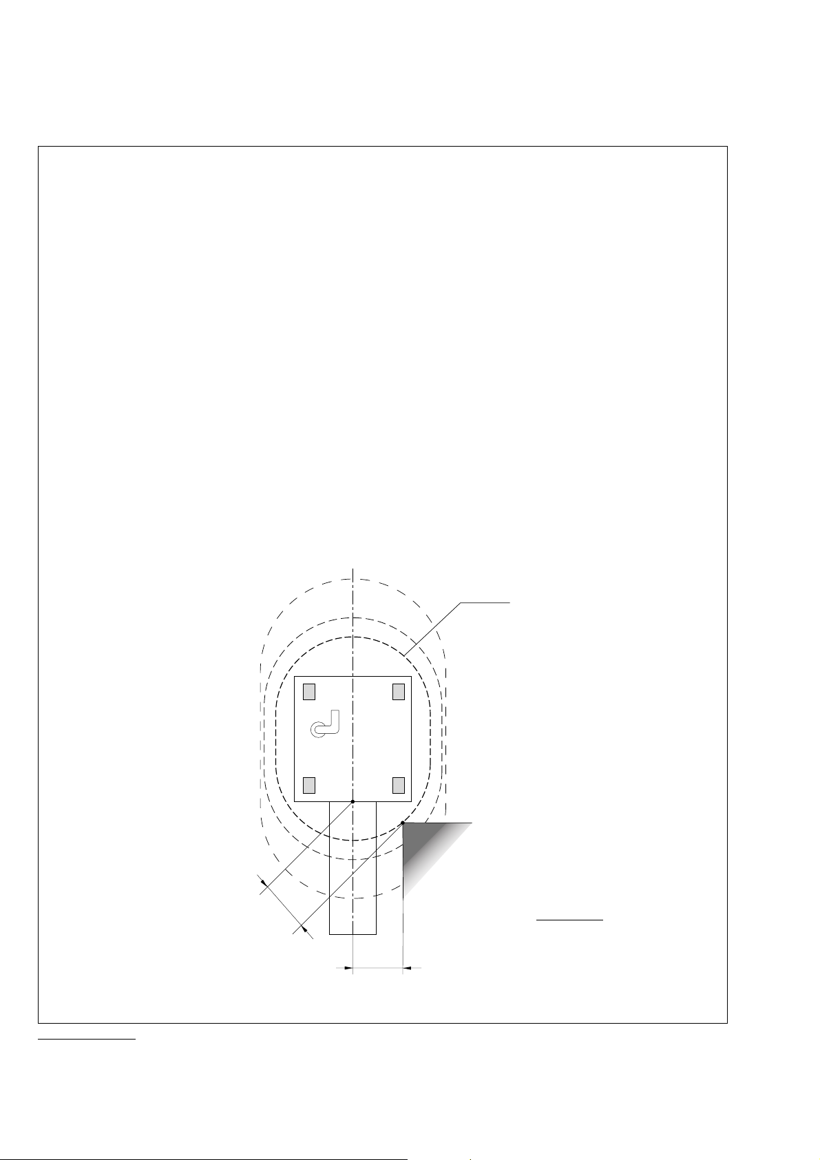
● Gerät außerhalb der 20 mT-Linie halten.
● Gerät bis zur 20 mT-Linie positionieren, jedoch
nicht näher als 1,5 m zur Mitte der Röhrenöffnung.
Antimagnetisches Bandmaß benutzen.
● Laufrollen des Fahrgestells feststellen.
● Position des Fahr-
gestells z. B. mit
gelb/schwarzem
Signalklebeband
am Boden
markieren und in
den GeräteAufstellungsplan
eintragen.
1,5 m
Kern-
spin-
tomograph
Scanner
● Keep the machine outside the 20mT-line.
● Position the machine outside the 20mT-line,
however not closer than 1.5 m from the center
of the tube opening.
Use antimagnetic tape measure.
● Lock castors of the
trolley.
20 mT
● Mark the position of
the trolley, e.g. by a
yellow-black tape on
the floor and put it
down on the installation plan of the
machine.
PM 8050 NMR
mit Titus NMR
PM 8050 MRI
with Titus MRI
minimaler Abstand
Minimum distance
1,5 m
27
Page 28

Titus NMR Titus MRI
Monitore aufstellen
Alle Monitore – mit Ausnahme vom Volumeter 3000/
2000 K – müssen in einem größeren Abstand vom
Tomographen betrieben werden als das Anästhesiegerät mit Kreissystem, da sie durch Magnetfelder und
Hochfrequenz beeinflußt werden (Bildstörungen, Fehlfunktionen).
Das Meß- und Warngerät Oxydig kann zwar bis außerhalb des 30 mTesla-Bereiches installiert und betrieben
werden, es empfiehlt sich jedoch dieses Gerät neben
den übrigen Monitoren außerhalb des 20 mTesla-Bereiches zu plazieren.
Kabel und Schläuche zum Anästhesiegerät auf
dem Boden verlegen und zum Schutz gegen
Quetschen, Knicken und Stolpern mit einer
trittfesten Kabelabdeckung versehen.
Installing monitors
All monitors – except the Volumeter 3000/2000 K – must
be operated at a greater distance from the scanner than
an anaesthetic machine with circle system, as they are
influenced by magnetic fields and high frequency
(picture distortion, malfunctions).
The Oxydig measuring and warning device can be
installed and operated outside the 30 mTesla area. It is,
however, recommended that this device is placed next to
the other monitors, outside the 20 mTesla area.
The hoses and cables to the anaesthetic
machine must be laid along the floor and
secured with a cable cover which will withstand
squashing, kinking and being tripped over.
Dokumentation der Geräte-Übergabe
● Vor der Geräte-Übergabe wird eine Funktionsprüfung
am Aufstellungsort durch den DrägerService durchgeführt.
● Die Inbetriebnahme* am Aufstellungsort und die Über-
gabe werden dokumentiert und von einem DrägerMitarbeiter und vom Betreiber der Anlage unterschrieben. Das Dokument enthält Angaben zu den Geräteabständen nach dem Aufstellungsplan des Kernspintomographen-Herstellers.
Dieses Dokument muß im medizinischen Produktebuch als Original oder Kopie hinterlegt werden.
Documentation of machine hand-over
● Before the machine is handed over, DrägerService
carry out a function check on-site.
● The start-up* and hand-over on site are documented
and signed by a Dräger representative and the user
of the unit. The record contains details of the
distances from the scanner, in accordance with the
scanner manufacturer's installation plan.
This document is an integral part of the Titus
MRI machine approval and the original, or a
copy, must be stored in the machine log.
28
Page 29

Titus NMR mit PM 8050
Übergabe-Protokoll und Geräte-Aufstellungsplan
Titus NMR mit PM 8050 NMR am Kernspintomographen
Hersteller des Anästhesiegerätes: Dräger Medical AG & Co. KGaA, Lübeck
Gerätetyp: Titus NMR
Hersteller des Kernspintomographen: _________________________________________________
Gerätetyp: _________________________________________________
Aufstellungsort: _________________________________________________
_________________________________________________
Datum der Aufstellung
des Anästhesiegerätes: _________________________________________________
Unterschriften
Dräger-Mitarbeiter: _________________________________________________
Betreiber: _________________________________________________
20 mT
Kern-
spin-
tomograph
Standorte
Diese Seite dient auch als Kopiervorlage.
PM 8050 NMR
mit Titus NMR
1,5 m
Abstände (cm)
x =
minimaler
Abstand
1,5 m
29
Page 30
Titus MRI with PM 8050 MRI
Hand-over record and machine installation plan
Titus MRI with PM 8050 MRI for MRI scanning
Manufacturer of anaesthetic machine: Dräger Medical AG & Co. KGaA, Lübeck
Machine type: Titus MRI
Manufacturer of MRI scanner: _________________________________________________
Machine type: _________________________________________________
Place of installation: _________________________________________________
_________________________________________________
Date of installation of
anaesthetic machine: _________________________________________________
Signatures
Dräger-representative: _________________________________________________
User: _________________________________________________
20 mT
MRI
Scanner
Machine locations
This page is also a copy master.
30
1,5 m
PM 8050 MRI
with Titus MRI
Distances (cm)
x =
Minimum
1,5 m
Page 31

Equipment CheckGeräte-Check
Geräte-Check
Eine Checkliste aus Kunststoff liegt dem Gerät bei.
● Checkliste in der Gebrauchsanweisung (S. 32/33)
dem Typ und dem Ausrüstungsstand des Gerätes
und der Zusatzgeräte anpassen – durch Streichungen
und Ergänzungen.
Die Checkliste enthält dann die Prüfungen, die
am Gerät vor jedem Einsatz durchgeführt
werden müssen.
● Außerdem eintragen:
Modellbezeichnung und Fabrikationsnummer des
Gerätes.
● Auf die Checkliste aus Kunststoff alle bleibenden
Eintragungen mit wasserfestem »Permanent«-Filzstift
übertragen.
● Checkliste kann mit der Kugelkette am Anästhesie-
gerät befestigt werden.
Equipment Check
A plastic checklist is supplied with the machine.
● By deleting and adding, adapt the checklist in the
Instructions for Use (pages 34/35) to cover the types
and variants of the equipment and accessories used.
This checklist will then contain all the checks
which have to be carried out on the equipment
before each use.
● In addition, add the following:
Model designation and serial number of the machine.
● All permanent entries on the plastic checklist must be
made in waterproof »permanent« felt-tip pen.
● Attach the checklist to the machine with the bead
chain.
Geräte-Check unmittelbar vor jedem Einsatz des
Gerätes durchführen!
● Alle Prüfungen in die Kunststoffcheckliste eintragen -
– mit Bleistift – in die IST-Spalte – mit Datum – und abzeichnen.
● Eintragungen vor der nächsten Prüfung ausradieren.
● Checkliste aus Kunststoff nicht mit Reinigungs- oder
Desinfektionsmitteln, Alkohol oder ähnlichen Lösungsmitteln abwischen: der wasserfeste Filzstift ist gegen
diese Mittel nicht beständig.
Carry out equipment check immediately before
each use!
● Enter all checks on the plastic checklist -
– in pencil – in the ACTUAL column – including date – and sign.
● Rub out all entries before the next check.
● Do not wipe the plastic checklist with cleaning agents,
disinfectants, alcohol or similar solvents, because the
waterproof felt-tip pen may be removed by these
agents.
31
Page 32

Geräte-Check
für Titus , Sulla 909, Trajan 808, Livius M
Vor Arbeitsbeginn vollständig prüfen.
Kenntnis der Gebrauchsanweisungen ist Voraussetzung.
Die mit P gekennzeichneten Prüfungen vor jedem
Patienten durchführen.
Anästhesiegerät, Fabr.-Nr.:
Ventilator, Fabr.-Nr.:
Monitor, Fabr.-Nr.:
Wenn Funktion erfüllt, im Kästchen abhaken!
Voraussetzungen
– Inspektionsintervalle von Gerät und Zubehör
eingehalten, siehe z. B. Prüfplaketten
– Gerät vollständig aufgebaut
– 2,3 L Atembeutel als Prüflunge auf den Patien-
tenanschluß des Y-Stücks oder des Filters (falls
vorhanden) gesteckt
– Anästhesiegasfortleitung an der Wandsteckdose
und an den Abgastüllen des Gerätes gesteckt
– Monitor (O2, P, V, CO2, Narkosemittel) einge-
schaltet, Selbsttest erfolgreich beendet, Senso-
ren kalibriert, Probenleitung für Gasmessung am
Luer Lock des Y-Stücks angeschlossen,
gewünschtes Narkosemittel gewählt
– Devapor (falls vorhanden) eingeschaltet
Prüfungen
Gasversorgung
● Reservegasflaschen (falls vorhanden) öffnen:
Druck O2 größer 50bar
Druck N2O größer 30bar
● Reservegasflaschen schließen
Zentralversorgung (falls vorhanden) :
Stecker für O2, AIR, N2O in
Entnahmeposition gesteckt
Meßröhren
für Sulla 909, Trajan 808 und Livius M :
● Umschalter AIR/N2O auf N2O schalten,
● O2-Dosierventil ganz öffnen:
O2-Flow vorhanden
● N2O-Dosierventil ganz öffnen:
N2O-Flow vorhanden
● Umschalter AIR/N2O auf AIR schalten:
kein N2O-Flow vorhanden
● AIR-Dosierventil ganz öffnen:
AIR-Flow vorhanden
● AIR-Dosierventil schließen,
● Umschalter AIR/N2O auf N2O schalten.
für Titus:
● Umschalter AIR/N2O auf N2O schalten,
● O2-Dosierventil ganz öffnen:
O2-Flow vorhanden
● N2O/AIR-Dosierventil ganz öffnen:
Flow in der N2O/AIR-Röhre vorhanden.
● Umschalter AIR/N2O auf AIR schalten:
Flow in der N2O/AIR-Röhre vorhanden
● AIR-Stecker ziehen:
kein AIR-Flow in der N2O/AIR-Röhre
● AIR-Stecker stecken,
● Umschalter AIR/N2O auf N2O schalten.
S-ORC Funktion
Schließverhalten
● O2-Dosierventil schließen:
kein N2O-Flow
Regelverhalten
● O2-Dosierventil auf 1,5 L/min einstellen:
N2O-Flow 3 bis 5 L/min
● O2- und N2O-Dosierventil schließen.
Vapor 19.n / Vapor 2000
Befestigung
P verriegelt, hängt frontal u. seitlich senkrecht
Handrad
in Nullstellung und eingerastet
P Füllstand zwischen min. und max.
Interlock (falls vorhanden)
P Verriegelungsfunktion in Ordnung
Sicherheitsfüllvorrichtung
Verschlußschieber eingeschoben
und gesichert
oder
Quik Fil Vorrichtung bzw. Schalefüllvorrichtung
Verschlußschraube festgeschraubt
Devapor (falls vorhanden)
Befestigung
P verriegelt und gleichmäßig aufliegend
Handrad
in Nullstellung und eingerastet
P Füllstand halbvoll bis max.
Lampe "Betrieb" leuchtet
Sicherheitsfüllvorrichtung
Füllöffnung verschlossen und nach
unten zeigend
32
Page 33

Kreissystem
Ventilscheiben, Ventilstifte in korrektem Zustand
Überwurfmuttern fest angeschraubt
Atemkalk
ausgetauscht bzw. kein Farbumschlag
Dichtheit
P ● Druckbegrenzungsventil auf "MAN" schalten
und auf 70 mbar stellen,
Für Sulla 909, Trajan 808 und Livius M:
P ● O2-Dosierventil auf 0,12 L/min einstellen,
P ● O2-Flush drücken und Druck ca. 30 mbar aufbauen:
P Druck bleibt konstant oder steigt an
● Druckbegrenzungsventil auf "SPONT" schalten:
Druck fällt ab
● Druckbegrenzungsventil auf "MAN" schalten,
● Vapor auf die kleinste, am Handrad angegebene
Konzentration stellen,
● O2-Flush drücken und Druck ca. 30 mbar aufbauen:
Druck bleibt konstant oder steigt an
● Vapor wieder auf 0 stellen.
● Druck entlasten:
Hebel des Druckbegrenzungsventils drücken.
Für Titus:
P ● Prüflunge abnehmen
P ● Schlauch vom Atembeutel abnehmen und auf den
Patientenanschluß bzw. auf den Filter stecken.
P ● O2-Flush drücken und Druck ca. 30 mbar aufbauen:
P Zeit für Druckänderung von 30 mbar auf
20 mbar ist mindestens 16 Sekunden
● Druckbegrenzungsventil auf "SPONT" schalten:
Druck fällt ab
● Druckbegrenzungsventil auf "MAN" schalten,
● Vapor auf die kleinste, am Handrad angegebene
Konzentration stellen,
● O2-Flush drücken und Druck ca. 30 mbar aufbauen:
Zeit für Druckänderung von 30 mbar auf 20 mbar
ist mindestens 16 Sekunden
P ● Schlauch vom Y-Stück bzw. Filter ziehen und auf
den Atembeutel stecken.
P ● Y-Stück dichthalten,
P ● O2-Flush drücken und Druck ca. 30 mbar aufbauen:
Der Atembeutel wird beim Drücken nicht entleert.
● Vapor wieder auf 0 stellen.
P ● Prüflunge wieder aufstecken.
Inspirations- und Exspirationsventil
● Druckbegrenzungsventil auf 30 mbar stellen,
● O2-Flush drücken und Druck ca. 30 mbar aufbauen:
Der Atembeutel für Handbeatmung füllt sich.
O2-Konz. am Monitor größer als 80 Vol.%.
Ventilscheibe im Insp.-Ventil bewegt sich beim
Drücken des Atembeutels für Handbeatmung.
Ventilscheibe im Exsp.-Ventil bewegt sich
beim Entlasten des Atembeutels.
Prüflunge am Patientenanschluß füllt und entleert
sich im Rhythmus der manuellen Beatmung.
Keine Widerstände bei der manuellen Beatmung
spürbar, die auf eine Stenose hindeuten.
Druckbegrenzungsventil
● O2-Dosierventil auf 5 L/min einstellen:
Anzeige am Monitor: 25 bis 35 mbar
Ventilator
● Hubvolumen auf 600 mL stellen
● Frequenz auf 10/min stellen
● PEEP auf "12 Uhr-Position" stellen
● andere Parameter: auf "grüner Punkt" stellen
Zulässige Anzeige am Monitor
Hubvolumen 450 bis 750 mL
Frequenz 8 bis 12/min
PEEP vorhanden
● Ventilator abschalten,
● PEEP auf 0 stellen,
● O2-Dosierventil schließen,
● Monitor auf Standby schalten.
Sekretabsaugung
P ● Absaugung einschalten,
P ● Absaugeschlauch abknicken:
Anzeige am Druckmesser zwischen
– 0,5 und – 0,9 bar
P ● Unterdruck patientengerecht einstellen und
Absaugung ausschalten.
Atembeutel für Notbeatmung
Vorhanden und funktionsfähig.
Anästhesiegasfortleitung
Schwebekörper der AGS-Meßröhre
zwischen Minimum und Maximum
Vor der Konnektion des Patienten
P ● Atemvolumen und Frequenz patientengerecht
voreinstellen.
P ● Alarmgrenzen von O2 , P, V, CO2 und
Narkosemittel patientengerecht einstellen.
P ● Druckbegrenzungsventil patientengerecht
einstellen.
P ● Monitor auf das verwendete Narkosemittel
einstellen.
P ● Bei Monitoren mit absaugender Gasmessung:
Wasserabscheider entleeren.
P ● Bei Anwendungen mit elektrischem Kontakt
zum Patienten:
Potentialausgleich zwischen den Geräten
herstellen.
Wird eine der Prüfungen nicht erfüllt,
darf das Gerät nicht benutzt werden.
Geräte Check durchgeführt
Name:
Datum:
33
Page 34

Check List
for Titus, Sulla 909, Trajan 808, Livius M
All checks must be carried out before the equipment is used.
The person who carries out the checks must be fully conversant with the Instructions for Use .
Checks marked with a P must be carried out before use on each patient.
Anaesthesia machine,
Serial No:
Ventilator, Serial No:
Monitor, Serial No:
Tick each function when checks have been satisfactorily
completed.
Pre-conditions
– Inspection intervals for machines and accessories
not exceeded, eg. see check labels
– Machine fully assembled
– 2.3 L breathing bag fitted to patient connector
as test lung on the Y-piece or filter, whichever is
being used
– Anaesthetic gas scavenging hose connected to
terminal unit and to waste gas sockets on machine
– Monitor (O2, P, V, CO2, anaesthetic agent)
switched on, self-test carried out satsifactorily,
sensor calibrated, sampling line for gas monitoring
connected to Luer lock on the Y-piece, correct
anaesthetic agent selected
– Devapor (when being used) switched on
● Disconnect Air probe:
No AIR flow present in N2O/AIR flowmeter.
● Connect AIR probe,
● Turn AIR/N2O selector switch to N2O.
S-ORC Function
Shut-down
● O2 flow-control valve:
No N2O flow.
Control
● Set O2 flow -control valve to 1.5 L/min.:
N2O flow 3 to 5 L/min.
● CloseO2 and N2O flow-control valves.
Tests
Gas supply
● Open reserve gas cylinders (when present):
O2 pressure more than 50bar,
N2O more than 30bar.
● Close reserve gas cylinders.
Medical gas pipeline (when present):
Probes for O2, AIR, N2O connected to
terminal units
Flowmeters
for Sulla 909, Trajan 808 and Livius M:
● Turn AIR/N2O selector switch to N2O,
● Open O2 flow-control valve fully:
O2 flow present.
● Open N2O flow-control valve fully :
N2O flow present.
● Turn AIR/N2O selector switch to AIR:
No N2O flow present.
● Open AIR flow-control valve fully:
AIR flow present.
● Close AIR flow-control valve,
● Turn AIR/N2O selector switch to N2O.
forTitus:
● Turn AIR/N2O selector switch to N2O,
● Open O2 flow-control valve fully:
O
2 flow present.
● Open N2O/AIR flow-control valve fully:
Flow present in N2O/AIR flowmeter.
● Turn AIR/N2O selector switch to AIR:
Flow present in N
2O/AIR flowmeter.
Vapor 19.n / Vapor 2000
Fastening
P Latched down firmly and set vertically
Handwheel
In zero position and engaged
P Filling level between min. and max.
Interlock (when present)
P Locking function OK
Key-indexed filling system
Sealing key or pin inserted and
close tightly
or
Quik Fil system or Funnel filling system
Locking screw tight
Devapor (when present)
Fastening
P Latched down firmly and resting evenly on surface
Handwheel
In zero position and engaged
P Filling level between half full and max.
"Operation" light lit
Key-indexed filling system
Filling opening locked shut and pointing
downwards
34
Page 35

Circle system
Valve disks, valve supports in proper condition
Retaining nut screwed tight
Soda lime
Replaced or no discolouration
Leak-tightness
● Switch-pressure limiting valve to "MAN"
P
and set to 70 mbar,
For Sulla 909, Trajan 808 und Livius M:
P
● Set O2 flow-control valve to 0.12 L/min.,
P ● Press O2 flush; let presssure build up to ca. 30 mbar:
P Pressure remains constant or rises.
● Switch pressure-limiting valve to"SPONT":
Pressure drops.
● Switch pressure-limiting valve to "MAN",
● Set Vapor to lowest concentration shown on
handwheel,
Press O2 flush; let pressure build up to ca. 30 mbar:
Pressure remains constant or rises.
● Reset Vapor to 0.
● Release pressure:
Push lever on pressure-limiting valve.
For Titus:
P ● Remove test lung,
P ● Detach hose from breathing bag and connect to
patient connector or to filter.
P ● Press O2 flush; let pressure build up to ca. 30 mbar:
P Pressure change from 30 mbar to 20 mbar takes
at least 16 seconds.
● Switch pressure-limiting valve to "SPONT":
Pressure drops.
● Switch pressure-limiting valve to "MAN",
● Set Vapor to lowest concentration shown on
handwheel,
● Press O2 flush; let pressure build up to ca. 30 mbar:
Pressure change from 30 mbar to 20 mbar takes
at least 16 seconds.
P ● Detach hose from Y-piece or filter and fit to
breathing bag,
P ● Keep Y-piece sealed,
P ● Press O2 flush; let pressure build up to ca. 30 mbar:
Breathing bag does not empty when squeezed.
● Reset Vapor to 0.
P ● Reconnect test lung.
Inspiratory and expiratory valves
● Set pressure-limiting valve to 30 mbar,
● Press O2 flush; let pressure build up to ca. 30 mbar:
Breathing bag for manual ventilation fills.
O2 concentration on monitor more than 80 Vol.%.
Valve disc in insp. valve moves when breathing
bag is squeezed during manual ventilation.
Valve disc in exp. valve moves when breathing
bag is released.
Test lung on patient connection fills and empties
rhythmically during manual ventilation.
No resistance during manual ventilation which
might indicate stenosis.
Pressure-limiting valve
● Set O2 flow-control valve to 5 L/min.:
Display on monitor: 25 to 35 mbar.
Ventilator
● Set stroke volume to 600 mL,
● Set frequency to 10/min.,
● Set PEEP to "12 o'clcok position",
● Set other parameters to "green dot":
Display on monitor should be:
Stroke volume 450 to 750 mL
Frequency 8 to 12/min
PEEP present.
● Switch off ventilator,
● Set PEEP to 0,
● Close O2 flow-control valve,
● Switch monitor to Standby.
Secretion suction
P ● Switch on suction,
P ● Kink suction hose:
Display on pressure gauge between
– 0.5 and – 0.9 bar.
P ● Set negative pressure to suit patient's needs
and swich off suction.
Breathing bag for emergency ventilation
Present and ready for use
Anaesthetic gas scavenging
Float in AGS flowmeter between
minimum and maximum
Before connecting to patient
P ● Pre-set tidal volume and frequency to suit
patient's needs.
P ● Set alarm limits for O2 , P, V, CO2 and
anaesthetic agent to suit patient's needs.
P ● Set pressure-limiting valve to suit patient's needs.
P ● Set monitor to anaesthetic agent being used.
P ● For monitors with sidestream gas measurement
empty water trap.
P ● When there is electrical contact to patient:
Establish potential equalisation between
machines.
If any check cannot be carried out
satisfactorily, the machine must not be
used.
Machine check carried out
Name:
Date:
35
Page 36

Überprüfung vor jedem Einsatz/Always check just before use
Was/What Wie/How Soll/Desired Ist/Act.
Kopiervorlage für Ergänzungen/Copy master for remarks
36
Page 37

Betrieb
Frischgasversorgung
Operation
Fresh gas supply
Betrieb
Voraussetzungen für die Inbetriebnahme des Anästhesiegerätes:
● Betriebsbereitschaft geprüft
(Seite 52 bis 57),
● Check nach Checkliste durchgeführt
(Seite 32 bis 33),
● Kenntnis der Gebrauchsanweisungen aller Zubehör-
geräte, wie Kreissystem, Vapor, Beatmungsgerät,
Monitore usw.
Frischgasversorgung
Nur, wenn Titus zusätzlich mit Air als Drittgas versorgt ist:
1 Wahlschalter in gewünschte Stellung bringen:
»N2O«(O2 + N2O können dosiert werden)
oder
»Air« (O2 + Air können dosiert werden)
Mischtabelle Air/O2 und Air-Einstellungen auf der
nächsten Seite.
Je nach Stellung des Wahlschalters strömt durch die
rechte Meßröhre N2O oder Air.
Operation
Before operating the anaesthetic machine, make sure
that:
● Readiness for operation has been checked
(pages 52 to 57),
● Checks have been carried out according to the
checklist (pages 31, 34, 35)
● Instructions for Use of all accessories, such as the
Circle System, Vapor, anaesthetic machines, monitors, etc. are understood.
Fresh gas supply
Only for Titus, which has air supplied as a third gas:
1 Move selector switch to the desired position:
»N2O«(O2 + N2O can be metered)
or
»Air« (O2 + Air can be metered)
For Air/O2 mixtures, see table on the following page.
Depending on the setting of the selector switch, N2O or
Air flows through the right-hand flowmeter tube.
Bei integrierter Druckluftzusatzeinrichtung ist eine inspiratorische O2-Messung erforderlich.
2 Mit den Dosierventilen
Mischungsverhältnis und Flowmenge des Frischgases einstellen.
Erst nach dem Einstellen des
Frischgasflows:
3 Vapor einschalten:
weiße Taste gedrückt halten und
mit dem Handrad gewünschte
Konzentration einstellen
oder
»Aus« = Handrad auf »0«, Taste für
Nullpunktarretierung eingerastet.
● Y-Stück des fertig aufgerüsteten
Kreissystems über Maske oder
Tubus mit dem Patienten verbinden.
If an additional compressed air
device is integrated in the
system, inspiratory O
ment is required.
2 Set mixing ratio and flow of fresh
gas with flow control valves.
3
2
1
Only when fresh gas flow has
been set:
3 Switch Vapor on:
keep white button pressed and
set desired concentration with
handwheel
or
switch Vapor off: turn handwheel
to zero, with button for zero-point
lock engaged.
● Connect Y-piece of the completely
assembled circle system to patient
via mask or tube.
measure-
2
37
Page 38

Betrieb
Frischgasversorgung
Operation
Fresh gas supply
Variable O2-Konzentration durch
Mischung von Air und O
2
Variable O2 concentrations in
Air/O2 mixtures
Vol.% O2 Flow in L/min (Air + O2)
1 2 4 6 8 10 12
Air O2 Air O2 Air O2 Air O2 Air O2 Air O2 Air O2
21 1.0 0 2.0 0 4.0 0 6.0 0 8.0 0 10.0 0 12.0 0
30 0.9 0.1 1.8 0.2 3.5 0.5 5.3 0.7 7.1 0.9 8.9 1.1 10.6 1.4
40 0.8 0.2 1.5 0.5 3.0 1.0 4.6 1.4 6.1 1.9 7.6 2.4 9.1 2.9
50 0.6 0.4 1.3 0.7 2.5 1.5 3.8 2.2 5.1 2.9 6.3 3.7 7.6 4.4
60 0.5 0.5 1.0 1.0 2.0 2.0 3.0 3.0 4.0 4.0 5.0 5.0 6.0 6.0
70 0.4 0.6 0.8 1.2 1.5 2.5 2.3 3.7 3.0 5.0 3.8 6.2 4.6 7.4
80 0.3 0.7 0.5 1.5 1.0 3.0 1.5 4.5 2.0 6.0 2.5 7.5 3.0 9.0
90 0.1 0.9 0.3 1.7 0.5 3.5 0.8 5.2 1.0 7.0 1.3 8.7
100 0 1.0 0 2.0 0 4.0 0 6.0 0 8.0 0 10.0
Flow-Abweichungen bei der Anwendung mit »Air« sind dem Diagramm in
den technischen Daten (Seite 65) zu
Any flow deviations during use with
»Air« can be found in the graph given
in the Technical Data (page 65).
entnehmen.
38
Page 39
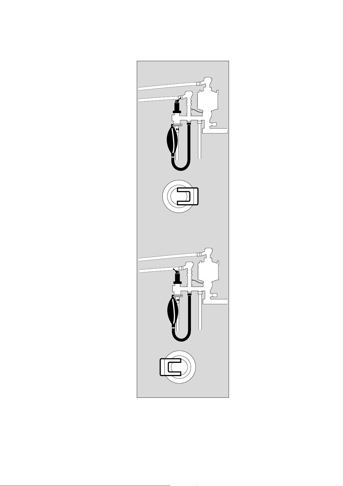
Betrieb
Betriebsarten
Operation
Operating modes
Betriebsarten
Spontanatmung
mit Kreissystem 9
1 Hebel am Druckbegrenzungs-
ventil auf Stellung »SPONT«
stellen, der Patient kann dann
über das Rückschlagventil frei
ausatmen.
2 Atembeutel ausreichend füllen –
stellt fertig dosiertes Frischgas für
Spontanatmung zur Verfügung.
Operating modes
Spontaneous breathing
with Circle System 9
1 Turn lever of pressure limiting
1
2
SPONT
SPONT
valve to the »SPONT« position;
the patient can now breathe out
freely via the check valve.
2 Fill the breathing bag sufficiently –
supplies ready-metered fresh gas
for spontaneous breathing.
Handbeatmung
mit Kreissystem 9
3 Hebel am Druckbegrenzungs-
ventil auf Stellung »MAN« stellen
und maximalen Atemwegsdruck
am Druckbegrenzungsventil
einstellen.
Beatmung von Hand mit
4 Atembeutel. Auf ausreichende
Füllung achten, Schlauch nicht
knicken oder abquetschen.
4
MAN
3
MAN
Manual ventilation
with Circle System 9
3 Turn lever on the pressure limiting
valve to the »MAN« position, and
set the maximum airway pressure.
Ventilate manually with
4 breathing bag. Make sure it is full
enough. Do not kink or squash
hose.
39
Page 40

Betrieb
Betriebsarten
Operation
Operating modes
Automatische Beatmung
mit Ventilog 2 oder Ventilog 3 und
Kreissystem 9. Dargestellt am
Beispiel Ventilog 2.
1 Hebel am Druckbegrenzungs-
ventil auf »MAN« und Druckbegrenzung an der Skala einstellen
und
2 Anästhesiebeatmungsgerät »Ven-
tilog« für die automatische Beatmung einstellen.
● das pneumatische Umschaltventil
schaltet auf »Autom.«.
● Am Ventilog Beatmungsmuster
einstellen – nach zugehöriger Gebrauchsanweisung.
Zur Überwachung der Beatmung:
● Patientenmonitor PM 8050
einschalten. Einstellen nach
zugehöriger Gebrauchsanweisung.
Automatic ventilation
with Ventilog 2 or Ventilog 3 and
Circle System 9. Shown with
Ventilog 2.
1
1 Turn the lever of the pressure
limiting valve to »MAN« and set
2
MAN
MAN
the pressure limit on the scale
and
2 Set the »Ventilog« anaesthetic
machine for automatic ventilation.
● the pneumatic switching valve
switches to »Autom.«.
● Set the ventilation pattern on the
Ventilog, according to the relevant
Instructions for Use.
To monitor ventilation:
● Switch on patient monitor
PM 8050. Set according to
relevant Instructions for Use.
Übergang von automatischer Beatmung auf Spontanatmung oder
Handbeatmung
● Ventilog ausschalten: Drehknopf
in Stellung »0« – das pneumatische Umschaltventil schaltet
automatisch auf
»SPONT / MAN« –
● weiter wie unter »Spontanat-
mung« oder »Handbeatmung« beschrieben.
Changeover from automatic
ventilation to spontaneous
breathing or manual ventilation.
● Switch off Ventilog: turn rotary
knob to »0« – the pneumatic
switching valve switches
automatically to
»SPONT / MAN« –
● Continue as for »Spontaneous
breathing« or »Manual ventilation«.
40
Page 41

Betrieb
Betriebsarten
Für den Notfalleinsatz
Operation
Operating modes
For emergency use
O2-Flush (Bypass) anwenden
● Knopf drücken –
O2 – ca. 55 L/min – strömt in das
Kreissystem zum Patienten unter
Umgehung von Meßröhrenblock
und Vapor.
● Sicherstellen, daß der Atemwegs-
druck nicht unzulässig hoch ansteigt!
Für den Notfalleinsatz
Magill-lnhalationseinrichtung*
Vor dem Anschluß des Patienten:
1 Hebel in vertikale Position nach
oben drehen – Rückatmung
(Ausatmung) in den Atembeutel ist
möglich.
2 Mit den Dosierventilen das
Mischungsverhältnis O2/N2O und
den Flow des Frischgases einstellen. Frischgasmenge = Minutenvolumen. Bei kleineren Frischgasmengen tritt partielle Rückatmung
und Atemgasmangel auf, der
Atembeutel wird leergeatmet
(Erstickungsgefahr!).
Frischgasflow erhöhen.
Using O2 flush (bypass)
● Press button –
O2 at about 55 L/min flows into
the circle system to the patient,
bypassing the flowmeter block
and Vapor.
Make sure that airway pressure
does not increase unduly!
For emergency use
Magill Inhalation System*
Before connecting to patient:
1
1 Turn the lever to the vertical
3
2
**
4
position – rebreathing (exhalation)
into the breathing bag is possible.
2 Set the O2/N2O mixing ratio and
the flow of the fresh gas using the
flow control valve. Fresh gas
volume = minute volume. Smaller
volumes of fresh gas result in
partial rebreathing** and shortage
of breathing gas, and the
breathing bag is emptied (danger
of suffocation!). Increase the
fresh gas flow.
3 Vapor einschalten:
Weiße Taste gedrückt halten und mit dem Handrad
die Konzentration einstellen.
Weitere Hinweise siehe Gebrauchsanweisung
des Vapor.
4 Überdruckventil gegen Uhrzeigersinn bis zum
Anschlag drehen = der mögliche Überdruck im
System wird damit auf ein Minimum gebracht.
Wird keine (oder nur partielle) Rückatmung
gewünscht:
1 Hebel ganz in horizontale (oder in schräge) Position
stellen.
● Frischgasmenge entsprechend erhöhen!
* Diese Einrichtung setzt Eigenatmung (Spontanatmung) des
Patienten voraus.
** Rückatmung verursacht erhöhte CO2-Konzentration im Atemgas.
3 Switch on Vapor:
Keep the white button pressed and set the
concentration with the handwheel.
For further information, see the »Vapor
Instructions for Use«.
4 Turn the pressure relief valve anti-clockwise as far as
it will go = this reduces any over pressure in the
system to a minimum.
If no rebreathing (or only partial rebreathing) is
required:
1 Turn lever to a horizontal (or slanted) position.
● Increase volume of fresh gas as a result!
* This device relies on the patient's own breathing (spontaneous
breathing).
** Return breathing causes increased CO2 concentration in the
breathing gas.
41
Page 42

Betrieb
Gebrauchsdauer überwachen
Maßnahmen bei Gasausfall
Operation
Checking use
What to do if gas supply fails
Gebrauchsdauer überwachen –
von CO
CO2-Absorber
Siehe Gebrauchsanweisung »Kreissystem 9«
Mikrobenfilter, Narkotika-Abluftfilter*
Siehe entsprechende Gebrauchsanweisung.
-Absorbern und Filtern
2
Maßnahmen bei Gasausfall
Für alle Geräte Titus – S-ORC ausgerüstet oder nicht,
mit Air versorgt oder nicht – gilt:
● Bei O
● Bei O
● Bei N
-Mangel oder Ausfall:
2
akustische Warnung, mindestens 7 Sekunden.
-Ausfall:
2
N2O-Zufuhr wird blockiert, N2O kann nicht mehr
dosiert werden.
O- oder Air-Mangel oder Ausfall:
2
Keine Warnung. Der Schwimmer in der rechten Meßröhre sinkt, oder er fällt ganz auf Null ab.
Checking use –
of CO
CO2 absorber
See »Circle System 9« Instructions for Use
Microbial filters, anaesthetic filters*
See relevant Instructions for Use.
absorbers and filters
2
What to do if gas supply fails
The following applies to all Titus machines – whether
fitted with S-ORC or not, or whether in a version with or
without air:
● If there is an O
acoustic alarm, for at least 7 seconds.
● If there is an O
N2O supply is blocked and N2O can no longer be
used.
● If there is an N
no alarm. The float in the right-hand flowmeter tube
falls, or drops right down to zero.
shortage or failure:
2
failure:
2
O or air shortage or failure:
2
Häufig kann die Ursache für die Unterbrechung der
Versorgung schnell beseitigt werden:
● Stecker aus der ZV-Entnahmestelle herausgezogen
oder in Parkstellung? Stecker wieder einstecken bis
zum Anschlag.
● Versorgungsschlauch abgeknickt? Knick beseitigen.
● Flasche leer? Gegen gefüllte wechseln.
Ist die Ursache nicht schnell zu beseitigen:
● Bei O
-Ausfall (Druckgas Air steht nicht zur
2
Verfügung):
Patient manuell beatmen, z. B. mit Resutator 2000.
● O
- und/oder N2O-Ausfall:
2
Notversorgung aus tragbarem Flaschenpaket.
The cause of a disruption in supply can often be
rectified quickly:
● Probe disconnected from medical pipeline system or
in standby position? Push probe in as far as it will go.
● Supply hose kinked? Straighten hose.
● Cylinder empty? Replace with full one.
If the cause cannot be rectified quickly:
● If there is an O
failure (medical air is not available):
2
ventilate patient manually with, for instance,
Resutator 2000.
If there is an O2 and/or N2O failure:
use emergency supply from portable cylinder pack.
*) Im Geltungsbereich der Europanorm nicht zugelassen. *) Nor allowed according to the European Standard.
42
Page 43

Betrieb
Zusätzliche Hinweise
Operation
Additional instructions
Zusätzliche Hinweise
– bei Titus mit S-ORC
– bei Titus mit Air-Versorgung
Titus mit S-ORC
S-ORC ist eine flow-abhängige Sicherheitseinrichtung.
Abhängig vom O2-Flow durch die Meßröhre wird der
maximale N2O-Flow begrenzt, so daß der prozentuale
O2-Anteil im Frischgas einen festgelegten Mindestwert
(21 Vol.%) nicht unterschreitet.
Das bedeutet: nicht nur bei O2-Ausfall ist die N2O-Zufuhr
blockiert, sondern auch bei versehentlich geschlossenem
O2-Dosierventil.
● O
-Dosierventil öffnen.
2
Titus mit Air-Versorgung
Additional instructions
– for Titus with S-ORC
– for Titus with air supply
Titus with S-ORC
S-ORC is a flow-dependent safety device.
Depending on the O2 flow through the measuring tube,
the maximum N2O flow is limited so that the O2 percentage in the fresh gas cannot fall below a minimum
value (21 vol.%)
This means that N2O supply is blocked not only when
there is an O2 failure, but also if the O2 flow valve has
been accidentally closed.
● Open O
Titus with air supply
flow valve.
2
Bei O2-Ausfall schaltet dieses Gerät automatisch auf
Air-Versorgung um, unabhängig von der Stellung des
Umschalters unter den Dosierventilen. Der N2O-Flow ist
blockiert, durch die N2O-Meßröhre fließt jetzt Air.
● Patient mit Air beatmen.
Wurde der Patient vor dem O2-Ausfall mit dem Anästhesiegas O2 + N2O beatmet:
● Auf alternative oder ergänzende Narkoseverfahren
ausweichen, Anästhesietiefe beibehalten.
Bei Air-Ausfall:
Keine Warnung, Schwimmer in der N2O/Air-Meßröhre
fällt auf Null. O2 kann weiterhin dosiert werden.
Nach jedem O2-Ausfall:
O2-Mangelsignal reaktivieren
Wenn die O2-Versorgung wiederhergestellt ist, muß ein
Versorgungsdruck von mindestens 2,7 bar für eine Zeit
von mindestens 20 Sekunden am Mangelsignal vorhanden sein. Während dieser Zeit keine O2-Verbraucher
einschalten, wie z. B. O2-Flush oder O2-Frischgasflow.
If there is an O2 failure this machine switches automatically to air supply, whatever the position of the
change-over switch below the flow valves. The N2O flow
is blocked and air now flows through the N2O flowmeter
tube.
● Ventilate patient with Air.
If the patient was being ventilated with O2 and N2O
anaesthetic gases before the O2 failure occurred:
● use alternative or supplementary anaesthesia
methods; maintain depth of anaesthesia.
If there is an air failure:
no alarm; float in the N2O/Air flowmeter tube drops to
zero. O2 can still be administered.
After each O2 failure:
Reset O2 shortage alarm
Once O2 supply is re-established, there must be a supply
pressure of at least 2.7 bar at the shortage alarm for at
least 20 seconds. During this period, do not switch on
any appliances which use O2, such as O2 flush or
O2 fresh gas flow.
43
Page 44

Betrieb
Betriebsende
Operation
End of use
Betriebsende
● Zuerst Vapor abschalten:
Handrad in Stellung »0«, Taste »0« muß einrasten.
● Patientenanschluß diskonnektieren.
● Dosierventile schließen in der Reihenfolge N
Ständiger Frischgasflow durch den CO2-Absorber
trocknet den Atemkalk aus!
Beim Unterschreiten einer Mindestfeuchte kommt es
unabhängig von der Kalkart und dem angewandten
Inhalationsanaesthetikum zu unerwünschten Reaktionen:
- Verminderte CO2-Absorption,
- Bildung von CO,
- Absorption und Zersetzung von Inhalationsanaesthetikum,
- erhöhte Wärmeentwicklung im Absorber und damit
erhöhte Atemgastemperatur.
Diese Reaktionen können zur Gefährdung des
Patienten in Form von CO-Vergiftung, nicht ausreichender Narkosetiefe und Verbrennungen in den
Atemwegen führen.
2
O – O2.
End of use
● First, switch off Vapor:
Handwheel in »0« position, »0« button must engage.
● Disconnect breathing hoses.
● Close flow valves in the sequence N
Continuous fresh gas flow through the CO2 absorber
dries out the soda lime.
Does the moisture fall below minimum, undesired
reactions, independent of the kind of lime and the
used inhalation anaesthetic agent, arise:
- reduced CO2 absorption,
- formation of CO,
- absorption and decomposition of the inhalation
anaesthetic agent,
- increased heat development in the absorber and
with this increased respiratory gas temperature.
These reactions can endanger the patient in form of
CO poisoning, insufficient depth of anaesthesia and
burns of the respiratory tracts.
O – O2.
2
N2O belastet die Umwelt!
Unnötigen Frischgasverbrauch vermeiden!
● Drehknopf am Ventilog in Stellung »0«.
● O
-, N2O- und Air-Stecker in »Parkstellung« bringen
2
oder ziehen.
Bei Versorgung aus Flaschen:
● Flaschenventile schließen.
● Zur Druckentlastung des Anästhesiegerätes zuerst
N2O-Dosierventil öffnen, danach O2-Dosierventil
öffnen, bis die Meßröhrenschwimmer vollständig
abgesunken sind.
● Dosierventile wieder schließen.
● Monitore abschalten.
N2O is detrimental to the environment!
Do not use more fresh gas than necessary!
● Turn rotary knob on Ventilog to »0« position.
● Put O
, N2O and air probes in »standby position« or
2
disconnect.
When supply is from cylinders:
● Close cylinder valves.
● To relieve pressure on the anaesthetic machine, open
N2O flow valve first, then open O2 flow valve until the
floats in the flowmeter tubes have dropped
completely.
● Close flow valves again.
● Switch off monitors.
44
Page 45

Pflege
Gerät abrüsten
Care
Stripping down machine
Pflege
Gerät abrüsten
Zusatzgeräte – wie Kreissystem, Ventilog, Monitore,
Vapor usw. – nach den zugehörigen Gebrauchsanweisungen pflegen.
● Alle Stecker aus den Wandentnahmestellen ziehen –
die Schläuche können am Gerät bleiben.
● Frischgasschlauch vom Kreissystem abschrauben,
der Schlauch bleibt am Anästhesiegerät.
● Pneumatisches Umschaltventil: alle Schläuche lösen,
Umschaltventil vom Kreissystem abschrauben,
Schläuche auch am Beatmungsgerät lösen.
● Kreissystem abrüsten, vom Anästhesiegerät
abnehmen und nach zugehöriger Gebrauchsanweisung weiterbehandeln.
Care
Stripping down machine
Ancillary equipment – such as
Circle System, Ventilog, monitors, vapor, etc. – see
relevant Instructions for Use.
● Disconnect all probes from wall terminals – the hoses
may remain on the machine.
● Disconnect fresh gas hose from Circle System – the
hose remains on the anaesthetic machine.
● Pneumatic switching valve: loosen all hoses,
disconnect switching valve from Circle System and
also loosen hoses on the ventilator.
● Strip down Circle System, remove from anaesthetic
machine and proceed according to relevant
Instructions for Use.
Magill-lnhalationseinrichtung
1 Maske von der Maskentülle
abziehen, Maskentülle aus dem
Atemschlauch ziehen, Atemschlauch und Atembeutel 2,3 L
vom Anschlußstück abziehen.
2 Anschlußstück vom Frischgas-
ausgang abschrauben.
Magill Inhalation Device
1 Detach mask from mask nozzle,
pull mask nozzle off the breathing
hose, disconnect breathing hose
and 2.3 L breathing bag from
connection.
2
2 Unscrew connector from
common-gas outlet.
1
45
Page 46

Pflegeliste für Narkosegerät Titus
Gültig für nicht infektiöse Patienten.
Bei einem infektiösen Patienten sind alle atemgasführenden Teile nach dem Desinfizieren und Reinigen zusätzlich zu sterilisieren.
Die Hier aufgeführten atemgasführenden Teile sind sterilisationsfähig, siehe Spalte „Sterilisieren".
Was Wie oft
Wiederaufbereitbare Aufbereitungsintervervalle
Komponenten
mit Filter am
Y-Stück
Titus Grundgerät täglich
Netzkabel, Druckgasschläuche, Kabel des monatlich
Potentialausgleichs
Narkosemittelverdunster
Vapor 19.n / Vapor 2000 täglich
Kreissystem 9
Metallteile wöchentlich wöchentlich täglich
CO2-Absorber und dessen Einsatz wöchentlich wöchentlich täglich
Umschaltventil ISO wöchentlich wöchentlich täglich
FGE-Umschaltventil wöchentlich wöchentlich täglich
Ventilscheiben (Kassette benutzen) wöchentlich wöchentlich täglich
Atembeutel mit Doppeltülle und Schlauch täglich täglich pro Patient
Atemschläuche täglich pro Patient pro Patient
Masken pro Patient pro Patient pro Patient
Frischgasschlauch wöchentlich wöchentlich wöchentlich
Y-Stück täglich pro Patient pro Patient
Wasserfallen täglich pro Patient pro Patient
Druckmeßschlauch wöchentlich wöchentlich täglich
Schlauch der Meßgasfortleitung bzw. Schlauch wöchentlich
der Meßgasrückführung
Patientenmonitore
PM 8050, PM 8060 wöchentlich wöchentlich wöchentlich
Volumeter 3000 wöchentlich wöchentlich täglich
Volumeter 2000 K (für Kinder) wöchentlich wöchentlich täglich
Oxidig täglich täglich täglich
Flow-Sensor wöchentlich wöchentlich täglich
O2-Sensor wöchentlich wöchentlich täglich
Temperatur-Sensor wöchentlich täglich täglich
Wasserfallen für Probeleitung täglich täglich täglich
Filter
Filter der Meßgasführung wöchentlich wöchentlich täglich
Mikrobenfilter 645 St - täglich -
AGS-System
Absaugeschlauch mit Stecker monatlich
Anschlußgehäuse AGS wöchentlich
Behälter für Puffervolumen AGS wöchentlich
Transferschlauch AGS wöchentlich
Flowröhre AGS (ohne Filter) wöchentlich
Abgastülle mit Rohr wöchentlich
Notbeatmung
Notbeatmungsbeutel, dessen Membran, Ventilunterteil
und Ventiloberteil
(Dräger Resultator 2000)
Silikonmanschette der Sekretauffangflasche und nach Bedarf
Spülflasche, deren Deckel mit Schwimmer, mindestens aber täglich
Absaugeschlauch und Schauglas
mit Filter auf Inspirations-
und Exspirationstülle
nach jeder Anwendung
1)
ohne Filter
1) Die Aufbereitungsintervalle richten sich nach der Verwendung und Plazierung der Filter. Die Tabelle beinhaltet lediglich Richtwerte. Die Anordnung des verantwortlichen Klinikhygienikers bleibt davon unberührt.
2) Nur Reinigungsmittel benutzen! Keine alkalischen oder chlorabspaltenden Desinfektionsmittel verwenden, Korrosionsgefahr.
3) Flächendesinfektionsmittel auf der Basis von Aldehyden, Alkoholen und quaternären Amoniumverbindungen verwenden, z. B. Buraton 10 F
(Schülke & Mayr GmbH) oder Incidin Perfekt (Henkel Hygiene GmbH).
46
Page 47

Desinfizieren und reinigen vorzugsweise in der Waschmaschine durchführen, sonst baddesinfizieren.
Titus und seine Komponenten nicht in Formaldehyd-Dampf und nicht in Ethylenoxid behandeln.
Wie
Desinfizieren und Reinigen Sterilisieren
Waschmaschine
93 °C 10 Minuten
nein außen nein nein
nein ja nein nein
nein außen nein nein
ja nein möglich ja
ja nein möglich ja
7)
möglich
7)
möglich
ja nein möglich ja
ja nein möglich ja
ja nein möglich ja
ja nein möglich ja
nein nur außen unter 50 °C nein
ja nein möglich ja
ja nein möglich ja
ja nein möglich ja
ja nein möglich ja
nein ja nein nein
nein nur außen nur spülen
nein nur außen nur spülen
nein ja nein nein
nein nur außen möglich
nein ja nein nein
nein nein nein ja
ja nein möglich ja
2)
Wischen
3)
Baden
4)
Dampf
134 °C 10 Minuten
nein möglich ja
nein möglich ja
5)
5)
6)
120 °C, 20 min
nein
nein
nein nur außen nein ja, max. 24 x
nein nur außen nein ja, max. 10 x
ja nein möglich nein
ja nein möglich nein
ja nein möglich ja
ja nein möglich nein
nein ja nein nein
ja nein möglich nein
ja nein möglich ja
ja nein möglich ja
4) Keine alkoholhaltigen Mittel verwenden.
5) Nicht ins Wasser legen und kein Wasser vorbeilaufen lassen!
6) Flow-Sensor ca. 1 Stunde in 70%-iger Ethanollösung desinfizieren, mindestens 30 Minuten ablüften lassen.
7) Nur neutrale Reiniger und VE-Wasser verwenden.
47
Page 48

Care list for Titus anaesthetic apparatus
Only for non-infectious patients.
When used with infectious patients, all parts in contact with breathing gas must additionally be sterilized after desinfection and cleaning.
What How often
Components which Conditioning intervals
can be conditioned
with Filter on
Y-piece
Titus Basic daily
Power cable, compressed gas hoses, monthly
equipotential bonding lead
Anaesthetic vaporiser
Vapor 19.n / Vapor 2000 daily
Circle system 9
Metal parts weekly weekly daily
CO2-absorber with insert weekly weekly daily
ISO changeover valve weekly weekly daily
FGE changeover valve weekly weekly daily
Valve disks weekly weekly daily
Breathing bag with breathing hose connector daily daily per patient
Breathing hoses daily per patient per patient
Masks per patient per patient per patient
Fresh gas hose weekly weekly weekly
Y-Piece daily per patient per patient
Water trap daily per patient per patient
Pressure gauge hose weekly weekly daily
Probe scavenging hose or weekly
Probe return hose
Monitor
PM 8050, PM 8060 weekly weekly weekly
Volumeter 3000 weekly weekly daily
Volumeter 2000 K (for children) weekly weekly daily
Oxidig daily daily daily
Flow-sensor weekly weekly daily
O2-sensor weekly weekly daily
Temperature sensor weekly daily daily
Water trap (monitoring) daily daily daily
Filter
Filter of the measured gas recirculation system weekly weekly daily
Microbial filter 645 St - daily -
AGS-System
Scavenging hose with connector monthly
AGS housing weekly
Container for AGS buffer volume weekly
AGS transfer hose weekly
AGS flow tube (without filter) weekly
Waste gas connector with tube weekly
Emergency breathing
Emergency breathing bag, its diaphragm and after each use
upper and lower valve parts
(Dräger Resultator 2000)
silicone sleeve of secretion collecting bottle and as requirement,
rinsing bottle, their lid with float, suction hose but at least daily
and inspection window
with Filter on
inspiration and
exspiration port
1)
without Filter
1) The conditioning intervals depend on the use and position of the filters. the table is merely intended as a rough guide. Zhe instructions of the
hospital´s hygiene officer shall prevail!
2) Only use cleaning agents, no alkaline or chlorine-releasing substances. Risk of corrosion.
3) Surface disinfectants based on aldehydes, alcohols and quaternary ammonium compounds, such as Buraton 10 F (Schülke & Mayr GmbH) or
Incidin Perfekt (Henkel Hygiene GmbH) can be used to ensure compatibility.
48
Page 49

Desinfizieren und reinigen vorzugsweise in der Waschmaschine durchführen, sonst baddesinfizieren.
Titus und seine Komponenten nicht in Formaldehyd-Dampf und nicht in Ethylenoxid behandeln.
How
Desinfection and cleaning Sterilization
Washing machine
93 °C 10 minutes
no only outside no no
no yes no no
no only outside no no
yes no possible yes
yes no possible yes
7)
possible
7)
possible
yes no possible yes
yes no possible yes
yes no possible yes
yes no possible yes
no only outside up to 50 °Cno
yes no possible yes
yes no possible yes
yes no possible yes
yes no possible yes
no yes no no
no only outside only rinse
no only outside only rinse
no yes no no
no only outside possible
no yes no no
no no no yes
yes no possible yes
2)
Wiping
3)
Immersion
4)
Steam
134 °C 10 minutes
no possible yes
no possible yes
5)
5)
6)
120 °C, 20 min
no
no
no only outside no yes, max. 24 times
no only outside no yes, max. 10 times
yes no possible no
yes no possible no
yes no possible yes
yes no possible no
no yes no no
yes no possible no
yes no possible yes
yes no possible yes
4) Do not use any agents containing alcohol.
5) Do not submerge in water.
6) Disinfect the flow sensor in 70%ethanoll solution for approx 1 hour and leave to dry in air for at least 30 minutes.
7) Use only pH-neutral detergent and distilled water.
49
Page 50

Pflege
Reinigung und Desinfektion
Care
Cleaning and disinfection
Reinigung und Desinfektion
● Grobe Verunreinigungen mit Einwegtüchern abwi-
schen.
Zur Desinfektion Präparate aus der Gruppe der Flä-
chendesinfektionsmittel verwenden – materialverträglich sind Präparate auf der Wirkstoffbasis von:
– Aldehyden
– quaternären Ammoniumverbindungen.
Nicht verwenden, weil sie möglicherweise materialschädigend sind:
– Präparate auf der Basis von halogenabspaltenden
Verbindungen
– starken organischen Säuren
– sauerstoff-abspaltenden Verbindungen.
Empfehlung für Anwender in Deutschland:
● Desinfektionsmittel, die in der DGHM-Liste einge-
tragen sind – die Liste nennt auch die Wirkstoffbasis
jedes Desinfektionsmittels –
DGHM – Deutsche Gesellschaft für Hygiene und
Mikrobiologie – DGHM-Liste – mhp-Verlag GmbH,
Wiesbaden.
Für Länder, in denen die DGHM-Liste nicht bekannt ist,
werden die vorher genannten Wirkbasen empfohlen.
Cleaning and disinfection
● Wipe off heavy dirt with disposable cloths.
For disinfecting, use preparations of the surface
disinfectants group – to avoid damaging the materials,
use preparations based on the following active
substances:
– Aldehydes
– Quaternary ammonium compounds.
Do not use the following products, because they may
damage the material:
– Preparations based on halogen-separating
compounds
– Strong organic acids
– Oxygen-separating compounds.
Recommendation for users in Germany:
● Disinfectants entered in the DGHM list – this list also
specifies the active substance on which each
disinfectant is based –
DGHM – Deutsche Gesellschaft für Hygiene und
Mikrobiologie – DGHM-List available from mhp-Verlag
GmbH, Wiesbaden.
For countries where the DGHM list is not known, the
active bases specified above are recommended.
Wischdesinfizieren
Titus, Vapor, Ventilog, Druckgas-Anschlußschläuche und
Steuerleitung des Umschaltventils
● keine alkoholhaltigen Mittel verwenden –
Empfehlung: z. B. Buraton 10 F –
Schülke & Mayr, Norderstedt –
Anwendungsvorschriften des Herstellers beachten.
Im Reinigungs- und Desinfektionsautomaten
naßthermisch desinfizieren
Verbindungsschlauch, Faltenbalg, Patientensystem,
Umschaltventil FGE, Umschaltventil und Abgastülle –
● 93 °C – 10 Minuten –
● nur mit Reinigungsmittel – kein Desinfektionsmittel
zusetzen – Teile können korrodieren!
● Umschaltventil FGE nach dem naßthermischen
Desinfizieren immer bei 134 °C in Heißdampf
sterilisieren.
Sonst gestörte Funktion weil sich noch Restflüssigkeit in den Steuerkanälen befinden kann!
Wipe disinfecting
Titus, Vapor, Ventilog, medical gas connection hoses and
control line of the changeover valve:
● Do not use any cleaning agents containing alcohol –
recommendation: e.g. Buraton 10 F –
Schülke & Mayr, Germany –
observe the manufacturer's Instructions for Use.
In cleaning and disinfecting machines
disinfect in liquid medium at high temperature
Connecting hose, bellows, patient system, FGE changeover
valve, changeover valve and waste gas nozzle –
● 93 °C – 10 minutes –
● only with cleaning agent – do not add disinfectant –
parts may corrode!
● After disinfection in washing machine, always
sterilise the FGE changeover valve at 134 °C in
autoclave.
Otherwise, operation may be disrupted because
residual liquid may remain in the control channels!
50
Page 51

Pflege
Sterilisation
Wartungs-/Instandsetzungsintervalle
Care
Sterilisation
Service/Maintenance intervals
Sterilisation
in Heißdampf (s. entspr. Spalte in Tabelle Seite 47).
Dampfsterilisation beschleunigt den natürlichen Alte-
rungsprozeß von Gummiteilen. Eine häufige Untersuchung auf Dichtheit und festen Sitz ist notwendig.
Mikrobenfilter nur in Dampf 134 °C sterilisieren.
Mehrmalige Sterilisation ist möglich (s. zugehörige
Gebrauchsanweisung).
Jede Sterilisation auf dem Filter markieren.
Nach der Pflege:
Gerät zusammenbauen und Betriebsbereitschaft
prüfen wie ab Seite 52 beschrieben!
Sterilisation
Steam autoclaving (see appropriate column in Table,
page 49).
Steam autoclaving accelerates the natural ageing
process of rubber parts. Frequent checks for leaks and
firm connection are essential.
Sterilise microbial filter in steam at 134 °C only.
Multiple sterilisation is possible (see relevant Instructions
for Use).
Mark each sterilisation on the filter.
After care:
Assemble the device and check readiness for
operation as described on page 52ff!
Wartungs-/Instandhaltungsintervalle
Gerät bzw. Geräteteile vor jeder Instandhaltungsmaßnahme – auch bei Rücksendung zu Reparaturzwecken – reinigen und desinfizieren!
Geräte-Inspektion halbjährlich
durch Fachleute
Sicherheitstechnische
Kontrollen
O
-Sensor austauschen,wenn Haltbar-
2
Steuermembran des
O
-Mangelsignals
2
Membran des S-ORC alle 5 Jahre austauschen
halbjährlich
durch Fachleute
keitsdatum überschritten
oder wenn keine Kalibrierung mehr möglich
alle 4 Jahre austauschen
durch Fachleute
durch Fachleute
Service/Maintenance intervals
Clean and disinfect device or device parts before
each maintenance operation, including when
returning for repair!
Apparatus Inspection Every 6 months
by an expert
Safety inspection Every 6 months
by an expert
Sensor Replace on reaching expiry
O
2
Control membrane of the
shortage threshold
O
2
signal
Membrane of S-ORC Should be replaced every
date or when calibration is
no longer possible
Should be replaced every
4 years by an expert
5 years by an expert
Membran der
Druckminderer
alle 6 Jahre austauschen
durch Fachleute
Membrane of the pressure
reducer
Should be replaced every
6 years by an expert
51
Page 52

Betriebsbereitschaft prüfen
Testing Readiness for Operation
Betriebsbereitschaft prüfen
– nach jeder Gerätepflege
Das Gerät ist vollständig aufgerüstet, mit Druckgasen
versorgt (Flaschen – wenn vorhanden – gefüllt),
CO2-Absorber gefüllt.
O2-Flaschen sind vollständig gefüllt, wenn der O2-Druckmesser 200 bar anzeigt. Bei diesem Druck enthält eine
3-L-Flasche 600 Liter, eine11-L-Flasche 2200 Liter entspanntes Gas.
Der N2O-Druck beträgt etwa 50 bar, solange flüssiges
Lachgas in der Flasche vorliegt. Bei der Gasentnahme
und der damit verbundenen Temperaturabsenkung kann
der Flaschendruck zwischenzeitlich unter 50 bar absinken. Der Flüssigkeitsvorrat von Lachgasflaschen kann
nur durch Wiegen festgestellt werden. Eine gefüllte
3-L-Flasche (2,25 kg Füllgewicht) enthält etwa 1125 Liter,
eine 11-L-Flasche (8 kg Füllgewicht) enthält etwa
4000 Liter entspanntes Lachgas.
Testing Readiness for Operation
– after completion of each care procedure
Completely re-assemble the machine and supply with
compressed gases (cylinders – if available – filled);
CO2 absorber filled.
O2 cylinders are completely charged if the O2 pressure
gauge indicates 200 bar. At this pressure, a 3-L cylinder
contains 600 litres and 11-L cylinder contains 2200 litres
of expanded gas.
The N2 O pressure amounts to about 50 bar, as long as
liquid nitrous oxide is available in the cylinder. When gas is
extracted, the cylinder pressure may temporarily drop below
50 bar, as a function of the related temperature reduction.
The liquid content of nitrous oxide cylinders can only be
determined by weighing. A charged 3-L cylinder (2.25 kg
charging weight) contains about 1125 litres, and a charged
11-L cylinder (8 kg charging weight) contains about
4000 litres of expanded nitrous oxide.
Druckgasanschlüsse prüfen
Alle Versorgungsschläuche (aus zentraler Versorgungsanlage oder aus Flaschen) auf festen Sitz, Dichtheit und
einwandfreien Zustand prüfen (Sichtprüfung).
Sicherheitseinrichtungen prüfen
(Beschreibung der Sicherheitseinrichtungen Seite 61).
Für alle Geräte – mit oder ohne S-ORC, ob zusätzlich mit
Air versorgt oder nicht – gilt:
● N
O darf nicht fließen, wenn die O2-Druckgasversor-
2
gung unterbrochen oder ausgefallen ist
= Wirkung der N2O-Sperre bei Geräten ohne S-ORC
= Wirkung von S-ORC, wenn Gerät damit ausgerü-
stet ist (siehe Aufkleber »S-ORC« neben der
N2O -Meßröhre).
● Bei O
-Mangel oder -Ausfall ertönt ein akustisches
2
Warnsignal.
Checking compressed gas connections
Check all supply hoses (from pipeline system or
cylinders) for firm connection, leaks and general
condition (visual check).
Checking safety features
(Description of safety features, page 61).
For all devices – with or without S-ORC, and with or
without an additional air supply:
● N
O must not flow if the O2 compressed gas supply
2
has been interrupted or has failed
= effect of N2O cut-out for machines without S-ORC
= effect of S-ORC if machine is equipped with it
(see label »S-ORC« next to the N2O measuring
tube).
● If there is an O
shortage or failure, an acoustic alarm
2
sounds.
52
Page 53

Testing Readiness for OperationBetriebsbereitschaft prüfen
O2-Mangelsignal und N2O-Sperre prüfen
(alle Geräte)
● Bei Titus-Air: Umschalter am Meßröhrenblock in
Stellung »N2O« bringen.
● Dosierventile O
und N2O öffnen, Flow ca. 3 L/min.●
2
O2-Versorgung unterbrechen - Stecker aus der
Wandentnahmestelle ziehen oder Flaschenventil
schließen: nach kurzer Zeit muß für mindestens
7 Sekunden ein Warnton ertönen, der N2O-Flow
muß auf Null zurückgehen.
● Beide Dosierventile schließen und O
-Versorgung
2
wiederherstellen. Bei mindestens 2,7 bar Betriebsdruck ist das O2-Mangelsignal nach 20 Sekunden
wieder betriebsbereit. Während dieser Zeit weder
O2 noch N2O aus dem Gerät entnehmen.
S-ORC-Wirkung prüfen (Geräte mit S-ORC)
S-ORC begrenzt – abhängig vom O2-Flow - die max.
N2O-Flowmenge und sichert damit eine Mindest-O2-Konzentration. Zusätzlich verhindert S-ORC einen N2O-Flow,
wenn das O2-Dosierventil geschlossen ist.
● O
-Flow auf 1 L/min einstellen, dann N2O-Dosier-
2
ventil voll öffnen: es soll sich eine O2-Konzentration
zwischen 21 Vol.% und 27 Vol.% bzw. ein N2O-Flow
zwischen 2,7 L/min und 3,7 L/min maximal einstellen.
Checking O2 shortage alarm and N2O cut-out
(all Titus models)
● For Titus Air: set switch on flowmeter block to »N
position.
● Open O
and N2O; flow approx. 3 L/min.● Cut O
2
supply – disconnect probe from wall terminal or close
cylinder valve; after a short time an alarm tone must
sound for at least 7 seconds and the N2O flow must
return to zero.
● Close both flow-control valves and re-establish O
supply. After 20 seconds at a minimum of 2.7 bar
operating pressure, the O2 shortage alarm will be
operational again. During this time, no O2 or N2O
should be delivered by the machine.
Checking S-ORC (machines with S-ORC)
S-ORC limits the max. N2O flow as a function of the
O2 flow, and thereby guarantees a minimum O
2
concentration. S-ORC also prevents N2O flow if the
O2 valve is closed.
● Set O
flow to 1 L/min, and then open the N2O flow
2
control valve completely. There should be an O
2
concentration of between 21 vol.% and 27 vol.%, or
an N2O flow of between 2.7 L/min and 3.7 L/min.
O«
2
2
2
● O
-Dosierventil schließen: der N2O-Flow muß konti-
2
nuierlich auf Null zurückgehen, d. h. es muß sich eine
O2-Konzentration von 100 Vol.% einstellen.
● O
-Dosierventil wieder öffnen, N2O fließt wieder.
2
● Prüfen, ob sich der Flow bei O
, N2O und Air auf
2
10 L/min einstellen läßt.
Umschalter / Gasart prüfen
nur an Geräten, die mit Air versorgt sind.
Geräte ohne Air-Versorgung: nur die Prüfung mit
100 Vol.% O2 und mit O2/N2O-Gemisch
● O
-Meßgerät (z. B. Oxydig) mit Sensor für die
2
1:1
durchführen.
Prüfung betriebsbereit halten.
● Schlauch vom Frischgasausgang abschrauben.
● Close the O
flow control valve: the N2O flow must
2
return to zero, i.e. there must be an O2 concentration
of 100 vol.%.
● Open the O
● Check whether the flow can be set to 10 L/min for
valve again; N2O flows again.
2
O2, N2O and Air.
Checking selector switch and gas type
only on machines which have an air supply.
Machines without air supply; carry out the check with
100 vol.% O2 and with O2/N2O mixture 1:1.
● Keep O
measuring device (e.g. Oxydig) with sensor
2
in operation for the test.
● Unscrew hose from fresh-gas outlet on Titus.
53
Page 54

Betriebsbereitschaft prüfen
Testing Readiness for Operation
Umschalter in Stellung »N
● O
-Flow = 3 L/min einstellen.
2
● O
-Sensor unter den Frischgas-
2
O«
2
ausgang halten und Gas über den
Sensor strömen lassen: am
-Meßgerät muß die O2-Kon-
O
2
zentration deutlich in Richtung
100 Vol.% O
● N
O-Dosierventil öffnen, Flow =
2
steigen.
2
3 L/min einstellen: die O2-Konzentration muß deutlich in Richtung 50 Vol.% fallen.
● O
-Versorgung unterbrechen: ZV-Stecker ziehen oder
2
Flaschenventil schließen.
Das Gerät muß automatisch umschalten auf Air –
durch die rechte Meßröhre muß jetzt Air fließen.
Nachprüfen mit O2-Meßgerät:
Soll-Anzeige 21 ±3 Vol.% O2. Das O2-Mangelsignal
ertönt.
● Beide Dosierventile schließen, O
-Versorgung wieder
2
herstellen.
Selector switch in »N2O« position
● Set O
● Hold O
flow = 3 L/min.
2
sensor under the fresh-
2
gas outlet and allow gas to flow
over the sensor: O2 con-centration on the O2 measuring device
must clearly increase towards
100 vol.% O2.
● Open N
O flow valve, set flow =
2
3 L/min: the O2 concentration
must clearly drop towards
50 vol.%.
● Cut the O
supply: pull out pipeline probes or close
2
cylinder valve: the machine must switch over
automatically to air – air must now flow through the
flowmeter tube on the right.
Check O2 concentration again: the display should
read 21 ±3 vol.% O2.
The O2 shortage alarm must sound.
● Close both flow valves; reconnect O
supply.
2
Umschalter in Stellung »Air«
● Beide Dosierventile öffnen und an beiden Meßröhren
den gleichen Flow – z. B. 3 L/min – einstellen.
● Prüfung mit O
-Meßgerät:
2
Soll-Anzeige ca. 60 Vol.% O2.
● O
-Versorgung unterbrechen. Das O2-Mangelsignal
2
ertönt, der Air-Flow muß unverändert bleiben.
● Prüfung mit O
-Meßgerät:
2
Soll-Anzeige 21 ±3 Vol.% O2.
● Beide Dosierventile schließen, O
-Versorgung wieder
2
herstellen.
Frischgasausgang noch offen halten für die nächste
Prüfung:
Selector switch to »Air« position
● Open both flow control valves and set the same flow –
e.g. 3 L/min – on both flowmeter tubes.
● Test with O
measuring device:
2
The display should read about 60 vol.% O2.
● Interrupt the O
supply. The O2 shortage alarm must
2
sound and the air-flow must remain unchanged.
● Test with O
measuring device:
2
The display should read 21 ±3 vol.% O2.
● Close both flow valves; reconnect O
supply.
2
Keep fresh-gas outlet open for the next test:
54
Page 55

Testing Readiness for OperationBetriebsbereitschaft prüfen
Niederdrucksystem auf Dichtheit prüfen
Diese Prüfung einmal mit Vapor (Handrad in Stellung
»0«) und einmal ohne Vapor (nur wenn Vapor abnehmbar, nicht, wenn fest angeschraubt) durchführen.
Prüfmittel:
O2-Meßröhrenblock
Druckmeßgerät
Anschlußstücke
Anschluß- bzw. Verbindungsschläuche
● Schlauchverbindungen herstellen zwischen Test-
Meßröhrenblock und Druckmeßgerät, dann Schlauch
mit entsprechendem Anschlußstück am Frischgasausgang anschrauben.
● Das Dosierventil am Test-Meßröhrenblock schließen,
O2-Stecker in die Zentrale Gasversorgung stecken.
● Dosierventil am Test-Meßröhren-
block langsam öffnen und Druck
am Manometer zwischen 70 und
100 mbar halten. Bei Druck
zwischen 70 und 100 mbar darf
die Leckrate (= Flow am TestMeßröhrenblock) nicht größer als
0,1 L/min sein.
Leak test of low pressure system
Carry out this test once with Vapor (handwheel in
»0« position) and once without Vapor (only if Vapor is
detachable, not if fixed).
Test equipment:
O2 flowmeter block
Pressure gauge
Connectors
Hoses
● Connect hose between test flowmeter block and
pressure gauge; then tighten hose at fresh-gas outlet
with connectors.
● Close flow valve on test flowmeter block. Push
O2 probe into pipeline system.
● Slowly open flow valve on the test
flowmeter block and keep pressure
steady on pressure gauge, at
between 70 and 100 mbar. At a
pressure between 70 and 100
mbar, the leakage rate (= flow on
test flowmeter block) must not be
greater than 0.1 L/min.
max.
0,1 L/min
Abschließend:
● Frischgasschlauch wieder an den Frischgasausgang
des Anästhesiegerätes schrauben. Vapor wieder
aufsetzen.
Finally:
● Reconnect the fresh gas hose to the common-gas
outlet on the anaesthetic machine. Replace Vapor.
55
Page 56

Betriebsbereitschaft prüfen
O2-Flush (Bypass)
● O
-Flush drücken: aus dem Y-Stück des Kreis-
2
systems muß ein kräftiger Gasstrom austreten –
Y-Stück nicht verschließen.
Druckknopf wieder loslassen, der O2-Flow muß
aufhören.
Testing Readiness for Operation
O
Flush (Bypass)
2
● Press O
-Flush: the Y-piece on the circle system
2
must emit a strong flow of gas – do not close Y-piece.
Release button. The O2 flow should cease.
Kreissystem 9
● Frischgasschlauch und seine Anschlüsse auf
einwandfreien Zustand prüfen (Sichtprüfung).
● Funktionskontrolle nach Gebrauchsanweisung
»Kreissystem 9«.
Ventilog 2 oder 3
● Ventilog mit Druckgas versorgt,
Schlauch in Ordnung.
● Alle Verbindungen zwischen Ventilog, pneumatischem
Umschaltventil, Kreissystem und Atembeutel auf
festen Sitz prüfen.
● Funktionskontrolle des Ventilog nach zugehöriger Ge-
brauchsanweisung.
Bronchus-Absaugegerät
Funktionskontrolle nach zugehöriger Gebrauchsanweisung.
Circle System 9
● Check that the fresh gas hose and its connections are
in perfect condition (visual check).
● Check functioning according to »Circle System 9«
Instructions for Use.
Ventilog 2 or 3
● Ventilog supplied with compressed gas, hose in
order.
● Check all connections between Ventilog, pneumatic
switching valve, circle system and breathing bag for
firm connection.
● Check functioning of Ventilog according to relevant
Instructions for Use.
Bronchial Aspirator
Check functioning according to relevant Instructions for
Use.
Mikrobenfilter
Zustand und Einbau des Filters gemäß Gebrauchsanweisung »Mikrobenfilter« überprüfen.
Vapor
● Nur Vapor mit Stecksystem: Prüfen, ob der Vapor-
Steckadapter auf dem Stecksystem-Sockel (am Anästhesiegerät) plan aufliegt und das System verriegelt
ist.
● Füllstand prüfen, ggf. nachfüllen.
● Funktionskontrolle des Vapor nach zugehöriger
Gebrauchsanweisung.
Microbial Filter
Check condition and fitting of filter in accordance with
the recommendations contained in the »Microbial Filter«
Instructions for Use.
Vapor
● Only plug-in Vapor: Check that the Vapor plug-in
adaptor is fitted level onto the mounting (on the
anaesthetic machine), and that the system is locked.
● Check filling level; refill if necessary.
● Check functioning of Vapor according to its
Instructions for Use.
56
Page 57

Testing Readiness for OperationBetriebsbereitschaft prüfen
Anästhesiegasfortleitungssystem (AGS)
● Funktionskontrolle nach zugehöriger Gebrauchs-
anweisung.
Narkosegasfortleitung*
Bei Absaugung über Ejektoranlage:
● Prüfen, ob je ein Schlauch am Kreissystem und Beat-
mungsgerät angeschlossen ist (siehe Seite 22).
● Schläuche mit T-Stück verbinden.
● Stecker des Narkotika-Abluftschlauches in die Kupp-
lung der Absaugeanlage stecken – das Schauzeichen
an der Absaugekupplung zeigt »grün«, die Anlage ist
eingeschaltet.
Wenn keine Ejektoranlage vorhanden:
● Je eine Narkotikafiltereinrichtung* an den Abgastüllen
anschließen - Filter erneuert!
● Festen Sitz der Filter in den Gummimanschetten
prüfen.
Anaesthetic gas scavenging system (AGS)
● Check functioning according to the relevant
Instructions for Use.
Anaesthetic gas scavenging*
For scavenging via ejector unit:
● Check that the circle system and ventilator each have
a connecting hose (see page 22).
● Connect hoses to T-piece.
● Connect probe on anaesthetic scavenging hose into
terminal unit on the scavenging unit – »green«
indicator on the scavenging terminal unit shows that
the unit is switched on.
If no ejector unit is available:
● Connect an anaesthetic filtering device* to each of the
waste gas sockets – replace the filters!
● Check that the filters are firmly fitted to in rubber
cuffs.
Manuelle Beatmungsvorrichtung (Handbeatmungsbeutel) für die Notfallbeatmung
● Funktion durch Pumpen mit der Hand prüfen: beim
Zusammendrücken muß ein Luftstrom aus dem
Maskenkonus hörbar und spürbar austreten, nach
dem Loslassen muß der Beutel schnell seine
ursprüngliche Form wieder annehmen.
● Bei verschlossenem Maskenkonus (mit dem Hand-
ballen) darf sich der Beutel mit der Hand nur wenig
zusammendrücken lassen.
Monitore
● Funktionskontrolle der Monitore nach zugehörigen
Gebrauchsanweisungen.
Nach positivem Verlauf aller Prüfungen ist
das Gerät einsatzbereit.
Manual ventilation bag for emergency ventilation
● Check functioning by pumping by hand: when the
bag is squeezed, the air escaping from the mask
cone must be audible and obvious. When the bag is
released, it must rapidly resume its former shape.
● When mask connector is closed (with palm of hand),
it should only be possible to squeeze the bag a little.
Monitors
● Check functioning of monitors according to relevant
Instructions for Use.
After these tests have been carried out
successfully, the machine is ready for
operation.
*) Im Geltungsbereich der Europanorm nicht zugelassen. *) In the area of validity of the European Standard not licensed.
57
Page 58

Anhang
Funktionsschema
Appendix
Functional Diagram
Funktionsschema
Das nebenstehende Schema gilt für die maximale Ausrüstung von Titus: mit S-ORC (im Geltungsbereich der EN
sind nur Geräte mit S-ORC zugelassen) und mit Air als
Drittgas.
Versorgung des Gerätes mit den Druckgasen O2, N2O
und Luft (Air) aus Wandentnahmestellen einer zentralen
Versorgungsanlage (ZV) oder alternativ für die Versorgung mit O2 und N2O aus Druckgasflaschen 18.
Der Flaschendruck wird am Manometer 17 angezeigt
und im Druckminderer auf 5 bar reduziert.
Die Druckminderer 5.1 reduzieren den O2- und N2O-Druck
auf 2 bzw. 3 bar, der Druckminderer 5.2 den Air-Druck
von 5 auf 1,5 bar.
Die Gase N2O und Luft (Air) können nur alternativ dosiert
werden, abhängig von der Stellung »N2O« oder »Air« des
Umschalters 6. Beide Gase werden in derselben (rechten) Meßröhre dosiert (siehe auch Diagramm in den technischen Daten).
Der O2-Druck wird von einer Warneinrichtung 2, 3, 4 für
O2-Mangel (mit Signalpfeife) überwacht: bei O2-Druck
kleiner als 2,2 bar ertönt das Signal. Bei weiterem
O2-Druckabfall wird die N2O-Zufuhr – unabhängig von
der Stellung des Umschalters 6 - unterbrochen; das
Gerät schaltet automatisch im Steuerblock 7 auf »Air«
um. Steht der Umschalter 6 in Stellung »Air«, so bleibt
Druckluft auch bei O2-Mangel eingeschaltet. Im Falle
einer O2-Minderdosierung begrenzt S-ORC 8 den
N2O-Flow so, daß die O2-Konzentration im Mischgas
nicht unter 21 Vol.% sinkt. Bei abgestellter O2-Dosierung
oder unterbrochener O2-Versorgung wird ein
N2O-Flow verhindert.
O2-, N2O- und Air-Flow lassen sich an den Dosierventilen 9 einstellen und an den Meßröhren 10 ablesen.
Nach den Meßröhren werden die Gase zusammengeführt und durchströmen über die Anschlüsse 12 oder 13
den Narkosemittelverdunster 14, wo das Narkosemittel
hinzudosiert wird. Bei Verwendung des abnehmbaren
Verdunsters 14 mit Steckadapter sperrt das Stecksystem
13 die Anschlüsse nach außen hin ab, wenn der
Verdunster abgenommen ist und öffnet innen eine
Verbindung, so daß das Gas zum Frischgasausgang 16
strömen kann.
Das Sicherheitsventil 11 (nur bei Geräten mit S-ORC)
vor dem Eingang zum Vapor begrenzt den Druck in den
Meßröhren auf ca. 0,9 bar.
Mit dem O2-Flush 15 (Bypass) kann dem Frischgas ein
O2-Flow von ca. 55 L/min (abhängig vom Versorgungsdruck) ohne Beeinflussung der Druckverhältnisse (Ejektorsystem) zugemischt werden.
Functional Diagram
The diagram on page 60 applies to Titus with its maximum configuration, i.e. with S-ORC (In the area of
validity of the European Standard only devices with SORC are licensed.) and with Air as a third gas.
The machine is supplied with O2, N2O and air from a
pipeline system (PS) via wall terminal units. Alternatively,
O2 and N2O may be supplied from compressed gas
cylinders 18. Cylinder pressure is displayed on a
pressure gauge 17 and reduced by a pressure reducer
to 5 bar.
Pressure reducers 5.1 reduce the O2 and N2O pressure
to 2 or 3 bar; pressure reducer 5.2 reduces the air
pressure from 5 to 1.5 bar.
N2O and air can now be administered alternately,
depending on whether the selector switch 6 is in the N2O
or »Air« position. Both gases are administered via the
same (right) flowmeter tube (see also the diagram in the
Technical Data).
The O2 pressure is monitored by an O2 shortage alarm
2, 3, 4 (with whistle): the alarm sounds when the O
pressure is lower than 2.2 bar. If O2 pressure continues
to drop, the N2O supply – whatever the position of the
selector switch 6 – is interrupted and the machine
switches automatically to »Air« via the control block 7.
If the selector switch 6 is in the »Air« position, medical
air remains switched on even during O2 shortage. If the
O2 flow is inadequate, the S-ORC 8 limits the N2O flow,
so that O2 concentration in the mixed gas does not drop
below 21 vol.%. If the O2 flow is switched off, or the
O2 supply interrupted, the N2O flow is stopped.
O2, N2O and air flows can be set on the flow control
valves 9 and readings taken on the flowmeters 10.
Downstream of the flowmeters, the gases converge and
flow through connections 12 or 13 to the anaesthetic
vaporiser 14, where the anaesthetic agent is added.
When a detachable plug-in vaporiser 14 is being used,
the probe system 13 blocks off the connections to the
outside when the vaporiser is detached and opens an
internal connection so that the gas can flow to the freshgas outlet 16.
The safety valve 11 (only on machines with S-ORC),
upstream of the inlet to Vapor, limits the pressure in the
flowmeter to about 0.9 bar.
With the O2 flush 15 (bypass), an O2 flow of about
55 L/min (depending on supply pressure) can be added
to the fresh gas, without affecting the pressure ratios.
2
58
Page 59

Anhang
Funktionsschema
Appendix
Functional Diagram
English text see next page
18
17
11
O
2
1
5.1
Air N
O
2
17
18
1
1
2
5.2
5.1
3
4
6
Steuerblock
7
12
13
14
15
16
1 Druckgasanschluß mit Filter
2 Rückschlagventil
3 Speicher
4 Warneinrichtung für O2-Mangel
5.1 Druckminderer 5/3 bar für O2 und 5/2 bar für N2O;
5/1,5 bar, wenn ohne S-ORC
5.2 Druckminderer 5/1,5 bar (für Air)
6 Umschalter »N2O«/»Air«
7 Steuerblock
8.1 S-ORC-Steuerelement für O2-Mindestkonzentration
8.2 Durchflußwiderstand
10
8
S-ORC
9
9 Dosierventile
10 Flow-Meßröhren
11 Sicherheitsventil (nur bei S-ORC)
12 Vapor, fest angeschraubt
13 Stecksystem
14 Vapor mit Steckanschluß
15 O2-Flush (Bypass)
16 Frischgasausgang
17 Manometer für Flaschendruck mit Druckminderer 200/5 bar
18 Druckgasflaschen O2 und N2O
59
Page 60

Appendix
Functional Diagram
18
17
11
O
2
5.1
Air N
O
2
17
18
1
1
1
2
5.2
5.1
3
4
6
Control block
7
12
13
14
15
16
1 Compressed gas connections with filter
2 Non-return valve
3 Reservoir
4 Alarm for O2 shortage
5.1 Pressure reducers 5/3 bar for O2 and 5/2 bar for N2O;
5/1.5 bar on machines without S-ORC
5.2 Pressure reducer 5/1.5 bar (for Air)
6 Selector switch »N2O«/»Air«
7 Control block
8.1 S-ORC control element for minimum O
8.2 Flow resistance
9 Flow valves
concentration
2
10
8
S-ORC
9
10 Flowmeters
11 Safety valve (only for S-ORC)
12 Vapor, fixed
13 Plug-in system
14 Vapor, plug-in type
15 O2 flush (bypass)
16 Fresh-gas outlet
17 Pressure gauge for cylinder pressure with 200/5 bar pressure
reducer.
18 O2 and N2 O compressed gas cylinders.
60
Page 61

Anhang
Sicherheitseinrichtungen
Appendix
Safety Features
Sicherheitseinrichtungen
Alle Modelle Titus:
O2-Mangelsignal
Warnschwelle Warnung spätestens, wenn
der O2-Druck auf 1,8 bar
abgefallen ist.
Warnung Mindestens 7 Sekunden
konstanter, nicht abschaltbarer Alarmton.
Notwendiger O2-Druck ≥2,7 bar mindestens
zum Reaktivieren des 20 Sekunden lang;
Warnsignals während dieser Zeit keine
O2-Verbraucher einschalten,
z. B. O2-Flush o. O2-Flow.
Titus mit S-ORC:
O2-Verhältnisregelung
Um eine O2-Konzentration größer als 21 Vol.% im
Frischgas zu gewährleisten, ist das Narkosegerät mit
einer O2-Verhältnisregelung ausgestattet. S-ORC begrenzt den N2O-Flow in Abhängigkeit vom O2-Flow.
Bis zu einem O2-Flow von 200 mL/min wird N2O gesperrt, ab 200 mL/min langsam freigegeben.
Bei O2-Flow größer als 300 mL/min kann N2O zudosiert
werden, wobei S-ORC O2-Konzentrationen kleiner als
21 Vol.% verhindert.
Das Diagramm zeigt den Bereich der einstellbaren
O2/N2O-Verhältnisse.
Safety Features
All Titus models:
O2 shortage threshold
Alarm limit Warning at the latest when
O2 pressure has fallen
below 1.8 bar.
Warning At least 7 seconds of
continuous sound; alarm
tone cannot be switched off.
O2 pressure necessary ≥2,7 bar for at least
to reset the alarm 20 seconds; do not switch
on any appliances which use
O2 during this period such
as O2 flush or O2 flow.
Titus with S-ORC:
Oxygen Ratio Controller
To ensure that the O2 concentration in the fresh gas
always remains above 21 vol.%, the anaesthetic machine
is equipped with an O2 ratio controller. S-ORC limits the
N2O flow as a function of the O2 flow. Up to an O2 flow
of 200 mL/min, the N2O flow is stopped, and above
200 mL/min it is slowly released. For an O2 flow above
300 mL/min, N2O can be added while the S-ORC
prevents the O2 concentration falling below 21 vol.%.
The graph shows the range of adjustable O2/N2O ratios.
Verhältnis/Ratio
O2 / N2O
Minimale
O2-Konzentration
Minimum
O2 concentration
100/0
90/10
80/20
70/30
60/40
50/50
40/60
30/70
20/80
10/90
0/100
Am Meßröhrenblock
einstellbare Verhältnisse
Ratio set on the
measuring block
0
200 400 600 800 1000 3000 4000
O2-Flow (mL/min)
Rate
O2 / N2O
100/0
90/10
80/20
70/30
60/40
50/50
40/60
30/70
20/80
10/90
0/100
61
Page 62

Anhang
Sicherheitseinrichtungen
Appendix
Safety Features
S-ORC ist kein sauerstoffspezifisches
Überwachungsgerät!
Durch Zudosierung von Anästhesiemitteldämpfen verringert sich die O2-Konzentration im Frischgas.
Darum:
O2-Konzentration mit Monitor überwachen!
Wenn Titus mit »Air« als drittem Gas versorgt ist,
hängt die Frischgasdosierung – bei Ausfall eines Gases –
von der Stellung des Umschalters ab (»N2O« oder »Air«).
Schaltstellung »N2O« O2 + N2O können dosiert
werden, Luftzufuhr ist
automatisch gesperrt.
Bei O2-Mangel Automatische Umschaltung
oder Ausfall auf Air; N2O wird gesperrt.
Der Umschalter bleibt unabhängig davon in Stellung
»N2O«.
Bei N2O-Ausfall O2 ist weiterhin dosierbar.
Keine Warnung;
Schwimmer in der N2OMeßröhre fällt auf Null.
Schaltstellung »Air« O2 + Air können dosiert
werden, N2O-Zufuhr ist
automatisch gesperrt.
Bei O2-Mangel S-ORC ist in Schaltstellung
oder Ausfall »Air« nicht wirksam. Nur Air
kann uneingeschränkt
dosiert werden.
Bei Air-Ausfall O2 ist weiterhin dosierbar.
Keine Warnung;
Schwimmer in der AirMeßröhre fällt auf Null.
S-ORC is not oxygen monitoring
By adding anaesthetic agent, the O2 concentration in the
fresh gas is reduced.
Therefore:
Check the O2 concentration with monitor!
For Titus with »Air« supplied as the third gas
control of fresh gas flow – one of the gases fails –
depends on the position of the selector switch (»N2O« or
»Air«).
Switch in »N2O« position O2 + N2O can be metered;
air supply is automatically
cut off.
If O2 is inadequate or fails Automatic switch-over to air;
N2O is cut off. The selector
switch remains unchanged
in position in the »N2O« position.
If N2O fails O2 can still be metered.
No alarm; float in N2O
flowmeter tube drops to
zero.
Switch in »Air« position O2 + N2O can be metered;
air supply is automatically
cut off.
If O2 is inadequate or fails S-ORC is not effective in
the »Air« position. Only air
can be metered without
limit.
If Air fails O2 can still be metered.
No alarm; float in N2O
flowmeter tube drops to
zero.
Titus ohne S-ORC und ohne Air-Versorgung
Bei O2-Mangel Akustische Warnung, die
oder Ausfall N2O-Sperre schaltet die
N2O-Zufuhr ab.
Bei N2O-Ausfall O2 ist weiterhin dosierbar.
Keine Warnung;
Schwimmer in der N2OMeßröhre fällt auf Null.
62
Titus without S-ORC and without air supply
If O2 is inadequate or fails Acoustic alarm, the N2O
cut-out device switches off
the N2O supply.
If N2O fails O2 can still be metered.
No alarm; float in N2O
flowmeter tube drops to
zero.
Page 63

Anhang
Technische Daten
Appendix
Technical Data
Technische Daten
Umweltbedingungen
Bei Betrieb
Temperatur 15 bis 35 °C
(Gerätetemperatur muß der Umgebungstemperatur
angeglichen sein)
Luftdruck 700 bis 1060 hPa
Feuchte 20 bis 80 % rel. Feuchte
Bei Lagerung
Temperatur –10 bis 60 °C
Luftdruck 500 bis 1060 hPa
Feuchte 0 bis 80 % rel. Feuchte
Geräuschemission
Im Normalbetrieb keine
Alarmton ca. 73 dB (A)
Gasversorgung
Aus Zentraler Versorgungsanlage (ZV) mit folgenden
Anforderungen:
Druck O
2
Druck N2O 2,7 bis 6,0 bar
Druck Air 2,7 bis 6,0 bar
Gasreinheit gemäß Anforderungen des
Anschlußverschraubungen geräteseitig
(gem. EN 739)
2,7 bis 6,0 bar
Europäischen Arzneibuchs.
Technical Data
Ambient Conditions
During operation
Temperature 15 to 35 °C
(machine temperature must be at ambient
temperature)
Air pressure 700 to 1060 hPa
Humidity 20 to 80 % rel. humidity
During storage
Temperature –10 to 60 °C
Air pressure 500 to 1060 hPa
Humidity 0 to 80 % rel. humidity
Noise emission
During normal operation none
Alarm tone approx. 73 dB (A)
Gas supply
From pipeline system (PS) with the following
requirements:
O
pressure 2.7 to 6.0 bar
2
N2O pressure 2.7 to 6.0 bar
Air pressure 2.7 to 6.0 bar
Gas purity in accordance with require-
ments in European Pharmacopeia.
Connectors on machine (conform to EN 739)
für O
2
NIST
für N2O NIST
für Druckluft NIST
Wahlweise O2- und N2O-Versorgung aus
3-L- bzw. 11-L-Flaschen
Gasreinheit: Gemäß Anforderungen des
Europäischen Arzneibuchs.
Druckreduzierung: Über Druckminderer an den
Flaschen, ausgehender
Druck 5 bar.
Gasdosierung
● O
-Dosierung Fein-Dosierventil (5 Umdre-
2
hungen)
Meßbereich 0,5 bis 10 L/min O
2
(eine Meßröhre)
Meßfehler ±10 % v.angezeigten Wert
(20 °C, 1013 hPa) +15, –5 % beim kleinsten
Skalenwert
Meßröhren für Low-Flow (O2):
1. Meßröhre
Meßbereich (0,02 bis 0,5) L/min
for O
2
NIST
for N2O NIST
for medical air NIST
Optional O2 and N2O supply from
3-L or 11-L cylinders
Gas purity: in accordance with require-
ments in European Pharma-
copeia.
Pressure reduction: via pressure reducer on
cylinders, outlet pressure
5 bar.
Gas dosage
● O
dosage Fine dosing valve
2
(5 revolutions)
Measuring range 0,5 to 10 L/min O
2
(one flowmeter tube)
Tolerance ±10 % of displayed value
(20 °C, 1013 hPa) +15, –5 % for lowest scale
value
Flowmeters for low-flow (O2):
1st flowmeter tube
Measuring range (0.02 to 0.5) L/min
63
Page 64

Anhang
Technische Daten
Appendix
Technical Data
Gasdosierung (Fortsetzung)
Meßfehler ±10 % bzw. für
untere Skalenwerte +20 % / –10 %
oberer Skalenwert ±5 %
vom jeweils abgelesenen Wert,
2. Meßröhre
Meßbereich (0,55 bis 10) L/min
Meßfehler ±10 % bzw. für
untere Skalenwerte +20 % / –5 %
vom jeweils abgelesenen Wert,
● N
0-Dosierung Fein-Dosierventil
2
(5 Umdrehungen)
Meßbereich 0,5 bis 10 L/min N2O
(eine Meßröhre)
Meßfehler ±10 % v. angezeigten Wert
(20 °C, 1013 hPa) +5, –15 % beim kleinsten
Skalenwert
Meßröhren für Low-Flow (N2O):
1. Meßröhre
Meßbereich (0,02 bis 0,5) L/min
Meßfehler ±10 % bzw. für
untere Skalenwerte –20 % / +10 %
oberer Skalenwert ±5 %
vom jeweils abgelesenen Wert,
Gas dosage (cont.)
Tolerance ±10 % or for:
lower scale values +20 % / –10 %
upper scale value ±5 %
of the displayed value,
2nd flowmeter tube
Measuring range (0.55 to 10) L/min
Tolerance ±10 % or for:
lower scale values +20 % / –5 %
of the displayed value,
● N
O dosage Fine dosing valve
2
(5 revolutions)
Measuring range 0.5 to 10 L/min N2O
(one flowmeter tube)
Tolerance ±10 % of displayed value
(20 °C, 1013 hPa) +5, –15 % of smallest scale
value
Flowmeters for low-flow (N2O):
1st flowmeter tube
Measuring range (0.02 to 0.5) L/min
Tolerance ±10 % or for:
lower scale values –20 % / +10 %
upper scale value ±5 %
of the displayed value,
2. Meßröhre
Meßbereich (0,55 bis 10) L/min
Meßfehler ±10 % bzw. für
untere Skalenwerte +20 % / –5 %
vom jeweils abgelesenen Wert,
Wenn Titus zusätzlich mit Air versorgt:
● Umschalter »Air«/»N
O«, handbetätigt.
2
Stellung »Air«: O2 + Air kann dosiert
werden.
Stellung »N2O«: O2 + N2O können dosiert
werden.
● Air-Dosierung mit N
O-Dosierventil,
2
Air fließt durch die
N2O-Meßröhre.
Meßbereich 0,55 bis 10 L/min Luft
Ablesung entsprechend dem
Diagramm
Meßfehler ±20 % vom angezeigten
(20 °C, 1013 hPa) Wert)
*) Bei Low-Flow-Ausführung (Doppelmeßröhren)
1. Meßröhre 0,02 bis 0,5 L/min
2. Meßröhre 0,55 bis 10 L/min
2nd flowmeter tube
Measuring range (0.55 to 10) L/min
Tolerance ±10 % or for:
lower scale values +20 % / –5 %
of the displayed value,
If Titus is supplied with additional air:
● »Air«/»N
O« selector switch, manually operated
2
»Air« position: O2 + Air can be dosage.
»N2O« position: O2 + N2O can be dosage.
● Air metering with N
O dosing valve,
2
Air flows through the N2O
flowmeters.
Measuring range 0.55 to 10 L/min Air
*)
Display as shown in graph
*)
Tolerance ±20 % of the displayed
(20 °C, 1013 hPa) value
*) In low-flow version (double flowmeter tubes)
1st flowmeter 0.02 to 0.5 L/min
2nd flowmeter 0.55 to 10 L/min
64
Page 65

Anhang
Technische Daten
Appendix
Technical Data
O2-Flush (Bypass)
Liefermenge bei 5 bar: ca. 55 L/min O
Liefermenge bei 2,7 bar: ca. 35 L/min O
2
2
Narkosemittel-Dosierung durch:
● Dräger-Vapor
19.n; Einstellbereich für
Halothane-Vapor: 0,2 bis 4 Vol.% Halothane
Enflurane-Vapor: 0,2 bis 5 Vol.% Enflurane
Isoflurane-Vapor: 0,2 bis 5 Vol.% Isoflurane
Sevoflurane-Vapor: 0,3 bis 8 Vol.% Sevoflurane
● Dräger-Vapor
2000; Einstellbereich für
Halothane-Vapor: 0,2 bis 6 Vol.% Halothane
Enflurane-Vapor: 0,2 bis 8 Vol.% Enflurane
Isoflurane-Vapor: 0,2 bis 6 Vol.% Isoflurane
Sevoflurane-Vapor: 0,3 bis 8 Vol.% Sevoflurane
● Titus mit Vapor-Stecksystem:
Schnellwechselsystem für den Vapor.
Die Anschlüsse werden selbsttätig überbrückt und
gegen Atmosphäre abgeschlossen, wenn der Vapor
abgenommen ist.
● Ausstattung und technische Daten des Vapor:
siehe Gebrauchsanweisung, Vapor 19.n bzw.
Vapor 2000.
O2 Flush (Bypass)
Supply volume at 5 bar: approx. 55 L/min O
Supply volume at 2.7 bar: approx. 35 L/min O
Anaesthetic agent dosage with:
● Dräger-Vapor
19.n; Setting range for
Halothane-Vapor: 0.2 to 4 vol.% Halothane
Enflurane-Vapor: 0.2 to 5 vol.% Enflurane
Isoflurane-Vapor: 0.2 to 5 vol.% Isoflurane
Sevoflurane-Vapor: 0.3 to 8 vol.% Sevoflurane
● Dräger-Vapor
2000; Setting range for
Halothane-Vapor: 0.2 to 6 vol.% Halothane
Enflurane-Vapor: 0.2 to 8 vol.% Enflurane
Isoflurane-Vapor: 0.2 to 6 vol.% Isoflurane
Sevoflurane-Vapor: 0.3 to 8 vol.% Sevoflurane
● Titus with plug-in Vapor:
Rapid change system for Vapor.
The connections are automatically made and sealed
against atmosphere when Vapor is removed.
● Equipment and technical data of Vapor:
see "Vapor 19.n or Vapor 2000
Instructions for Use"
2
2
Dosierung von Air mit der N2 O-Meßröhre
12
11
10
9
8
7
6
5
4
3
tatsächlicher Flow/actual flow (L/min)
2
1
Dosage of air with the N2 O flowmeter tube
0
0
0 1 2 3 4 5 6 7 8 9 100
abgelesener Skalenwert/displayed scale value (L/min)
65
Page 66

Anhang
Technische Daten
Appendix
Technical Data
Frischgasausgang am Titus
● Anschluß nach ISO:
● Gerade Tülle, Ausgang waagerecht nach links
weisend
Sicherheitseinrichtungen
Beschreibung siehe Seite 61
–O2-Mangelsignal
–N2O-Sperre (wenn ohne S-ORC)
– S-ORC (Sensitive Oxygen Ratio Controller),
N2O-Sperre entfällt.
Kreissystem
Ausstattung und technische Daten: siehe Gebrauchsanweisung »Kreissystem 9«
Anschluß für den Frischgasschlauch:
Außengewinde M 16 x 1,5
Abmessungen und Gewichte
Gewicht:
Gerät mit Vapor 19.n
und Kreissystem 22 kg*
Common-gas outlet on Titus
● Connector according to ISO:
● Straight nozzle, outlet pointing horizontally to left
Safety features
Description see page 61
–O2 shortage alarm
–N2O cut-out device (if no S-ORC)
– S-ORC (Sensitive Oxygen Ratio Controller), with
S-ORC the N2O cut-out device is not needed.
Circle system
Equipment and technical data: see »Circle System 9«
Instructions for Use
Fresh gas inlet connector:
male thread M 16 x 1.5 mm
Dimensions and weights
Weight:
Machine with Vapor 19.n
and circle system 22 kg*
Gerät mit Vapor 19.n
ohne Kreissystem 16 kg*
Abmessungen in mm siehe Abbildung
*) Das Gewicht erhöht sich bei der Verwendung des Vapor 2000 um
ca. 1 kg.
max. 134°C
5
10
30
50
70
Machine with Vapor 19.n
without circle system 16 kg*
Dimensions in mm see drawing
*) The weight increases by around 1 kg at the use of the
Vapor 2000.
594,0
453,5
66
233,0
391,0
218,0
305,0
Page 67

Page 68

Diese Gebrauchsanweisung gilt nur für
Titus
mit der Fabrikations-Nr.:
Ohne von Dräger eingetragene Fabrika-
tions-Nr. informiert diese Gebrauchsanweisung nur unverbindlich!
These Instructions for Use apply only to
Titus
with Serial No.:
If no Serial No. has been filled in by Dräger
these Instructions for Use are provided for
general information only and are not
intended for use with any specific
machine or device.
ç ç
Richtlinie 93/42/EWG
über Medizinprodukte
Directive 93/42/EEC
concerning Medical Devices
Dräger Medical AG & Co. KGaA
z Moislinger Allee 53 – 55
D-23542 Lübeck
y +49 451 8 82 - 0
FAX +49 451 8 82-20 80
! http://www.draeger.com
Dräger Medical AG & Co. KGaA
Germany
z Moislinger Allee 53 – 55
D-23542 Lübeck
y +49 451 8 82 - 0
FAX +49 451 8 82-20 80
! http://www.draeger.com
90 29 122 - GA 5232.301 de/en
Dräger Medical AG & Co. KGaA
3. Ausgabe - September 2003
Änderungen vorbehalten
90 29 122 - GA 5232.301 de/en
Dräger Medical AG & Co. KGaA
3rd edition - September 2003
Subject to alteration
 Loading...