

Page 1
Incubator 8000 NC
Instructions for Use
– Software 11.n –
D
1-151-94
Page 2

Contents
Contents
Page
For Your Safety and that of Your Patients................. 3
Intended Use.............................................................. 4
Preparation.................................................................5
Before using for the first time....................................... 5
Doors, ports and bed...................................................5
Connecting air temperature sensor.............................. 8
Fitting accessories ......................................................8
Preparing oxygen therapy accessories........................12
Routing cables and hoses.......................................... 13
Checking Readiness for Operation.......................... 14
Before using for the first time..................................... 14
Before each use.........................................................14
Page
Maintenance Intervals...............................................42
Disposal of NiCd batteries..........................................42
What's What..............................................................43
Technical Data..........................................................47
Description............................................................... 49
Design....................................................................... 49
Alarm hierarchy.......................................................... 50
Order List..................................................................51
Index......................................................................... 53
Operation..................................................................17
Precautions................................................................17
Controlling air temperature.........................................20
Using skin temperature control .................................. 23
ThermoMonitoring......................................................28
Using humidity control ...............................................29
Supplying oxygen.......................................................31
Using electronic baby scales...................................... 32
Using vacuum mattress.............................................. 32
Using phototherapy unit..............................................33
Using "BabyLink Incubator" interface......................... 33
Care.......................................................................... 34
Stripping down...........................................................34
Cleaning/disinfecting/sterilizing.................................. 35
Before re-using.......................................................... 37
Fault, Cause, Remedy...............................................38
2
Page 3

For Your Safety and that of Your
Patients
For Your Safety and that of Your Patients
For correct and effective use of the apparatus and to
avoid hazards it is essential to read the following recommendations and to act accordingly1):
Strictly follow the Instructions for Use
Any use of the apparatus requires full understanding and
strict observation of these instructions. The apparatus is
only to be used for purposes specified here.
Maintenance
The apparatus must be inspected2) and serviced2) regularly by trained service personnel at six monthly intervals
(and a record kept).
Repair2) and general overhaul of the apparatus may only
be carried out by trained service personnel.
We recommend that a service contract be obtained with
DrägerService and that all repairs also be carried out by
them. Only authentic Dräger spare parts may be used for
maintenance2).
Observe chapter "Maintenance Intervals".
Liability for proper function or damage
The liability for the proper function of the apparatus is
irrevocably transferred to the owner or operator to the
extent that the apparatus is serviced or repaired by
personnel not employed or authorized by DrägerService
or if the apparatus is used in a manner not conforming to
its intended use.
Drägerwerk Aktiengesellschaft cannot be held
responsible for damage caused by non-compliance with
the recommendations given above. The warranty and
liability provisions of the terms of sale and delivery of
Drägerwerk Aktiengesellschaft are likewise not modified
by the recommendations given above.
Drägerwerk Aktiengesellschaft
Power connection
The apparatus is to be used only in rooms with mains
power supply installations complying with national safety
standards (such as in F. R. of Germany: VDE 0107).
The requirements laid down in IEC 601-1 "Safety of
Medical Electrical Equipment" are applicable for
electrically powered equipment.
Not for use in areas of explosion hazard
This apparatus is neither approved nor certified for use in
areas where combustible or explosive gas mixtures are
likely to occur.
Safe connection with other electrical equipment
Electrical connections to equipment which is not listed in
these Instructions for Use should only be made following
consultations with the respective manufacturers or an
expert.
1)
Insofar as reference is made to laws, regulations or standards, these
are based on the legal system of the Federal Republic of Germany.
2)
Definitions according to DIN 31 051:
Inspection = examination of actual condition
Service = measures to maintain specified condition
Repair = measures to restore specified condition
Maintenance = inspection, service, repair
3
Page 4

Intended Use
Intended Use
Heat therapy for premature babies and sick neonates;
with control of air temperature and humidity; and also
skin temperature as an option.
The incubator must only be used by properly trained
staff under the supervision of qualified medical staff
who have up-to-date knowledge of the risks and
benefits of the use of incubators.
Do not use the skin temperature control on babies
who are in shock or who have high temperatures.
The air in the incubator should only be enriched with
oxygen when prescribed by a doctor. It is absolutely
essential that such oxygen enrichment is controlled
on the basis of the arterially-measured oxygen partial
pressure in the patient's blood. If this is not done
there is a risk of hyperoxaemia (damage to the eyes)
and hypoxaemia (damage to the brain).
Do not nebulize any medicaments or similar
substances in the patient's room. If nebulized
substances fall onto the incubator this may impair its
functioning.
Mobile telephones must not be used within 10 metres
of the incubator.
Mobile telephones may interfere with the functioning of
electro-medical equipment.
Maximum load must not exceed 25 kg.
Only connect incubator to a mains power socket.
Do not use a mains distribution board.
If there is a circuit breaker in the supply to the distribution
board the permitted limit for leakage currents might be
exceeded. There could then be an electrical risk for
patient and staff.
4
Page 5
Preparation
The incubator is supplied fully assembled.
Before using for the first time
● Check that all packaging material has been removed.
Doors, ports and bed
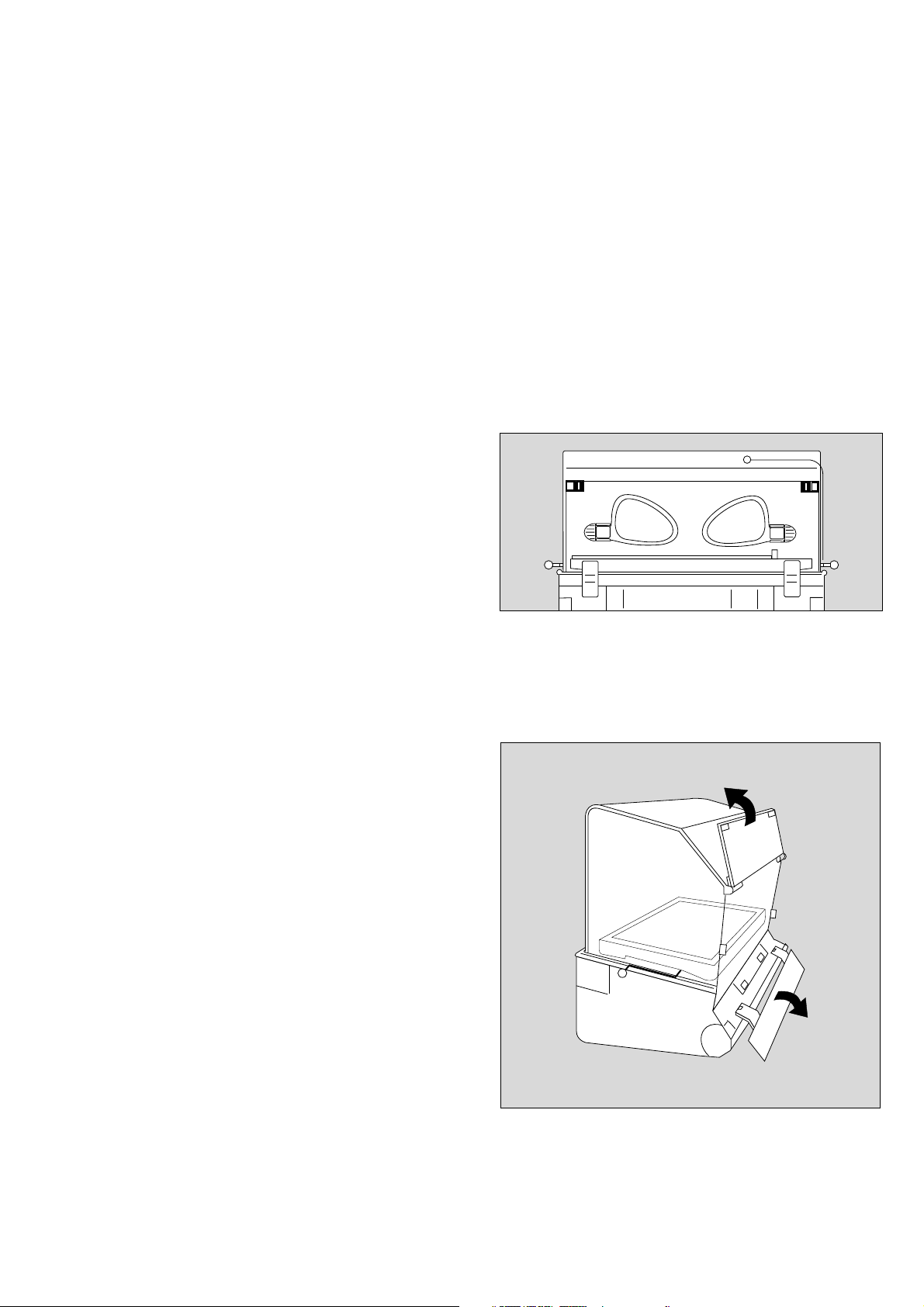
Front door
To open front door:
Preparation
Before using for the first time
Doors, ports and bed
1 Squeeze catches together with thumb and index
finger and at the same time lower front door until it
rests on housing.
To close front door:
● Lift up front door.
1 Squeeze catches together on both sides, push front
door forward and release catches. Push firmly on
front door to ensure that catches fully engage. Red
mark on catches should no longer be visible.
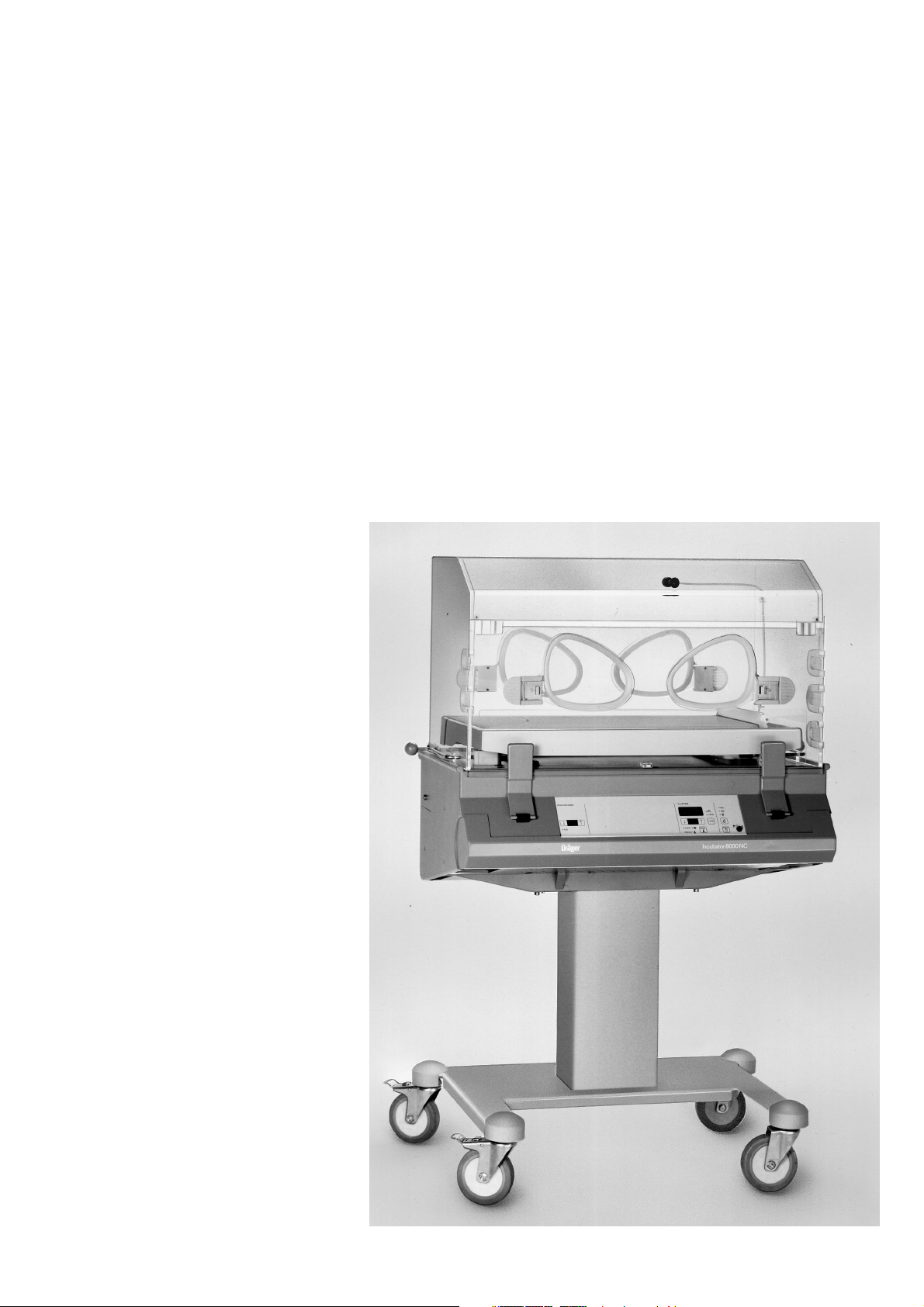
Divided front door, optional
To open front door:
● Squeeze catches on both sides together, and at
the same time fold upper section back until it rests on
sloping surface of canopy. It is then possible to attend
to the patient.
If necessary:
● Pull lower section down, pulling gently against pivots
to do so, and lower until it rests on housing.
1 1
To close front door:
● First lift up lower section and push back into place –
until it engages.
● Then fold upper section down and, while squeezing
catches on both sides together, push door back into
place – until it engages.
Red mark on catch should not be visible any more.
5
Page 6
Preparation
Doors, ports and bed
To open hand ports:
1 Press catch on serrated area to open hand port.
To close hand ports:
● Push hand ports back into place until catch is safely
engaged.
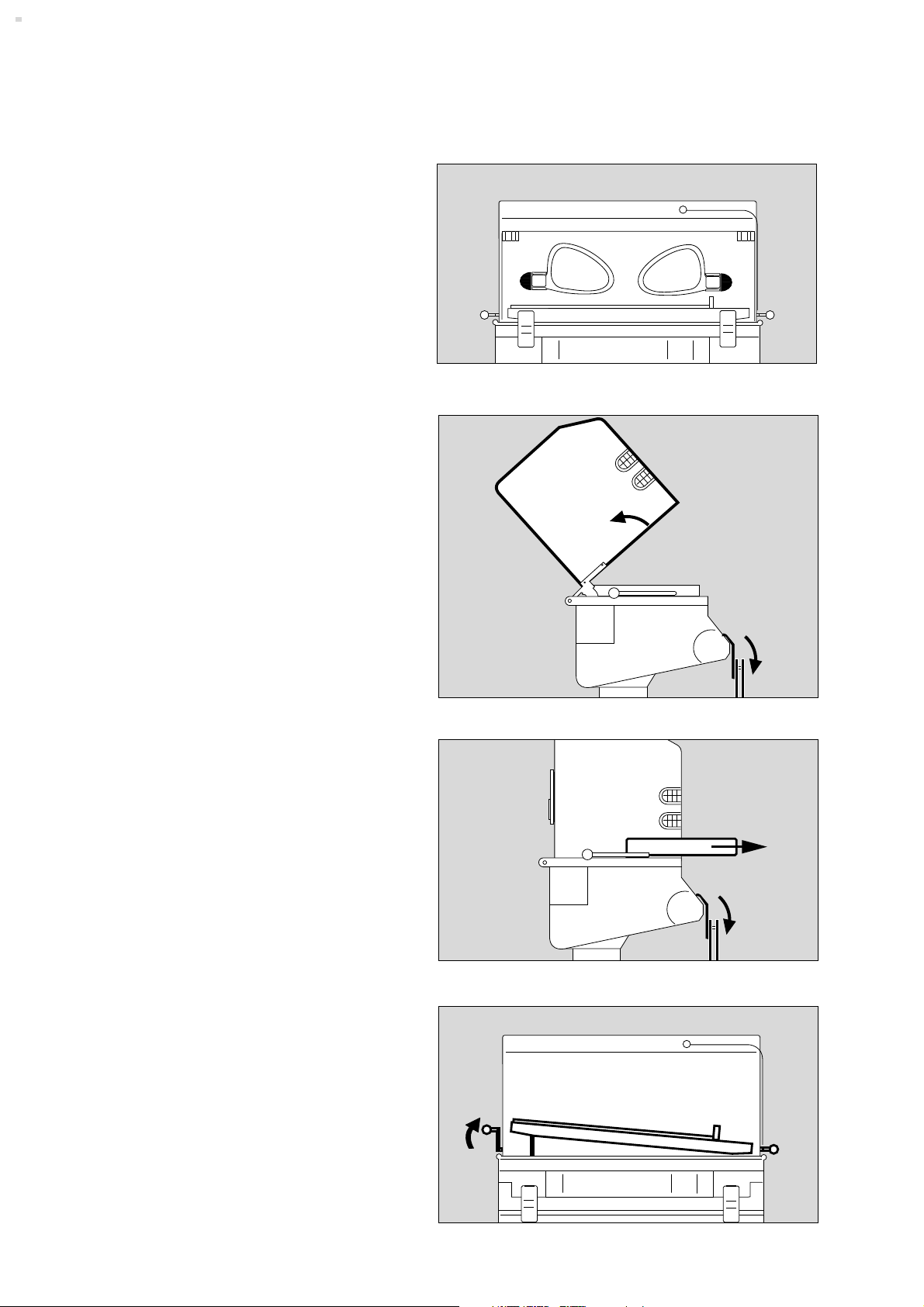
Canopy
To lift up canopy:
11
● Open front door.
● Tip canopy back as far as it goes.
Taking out the bed
● Open front door.
● Pull bed out forwards until it stops.
● After completing care procedure, push bed back as
far as it will go and close front door.
Tilting the bed
● Raise left lever until it engages to lift left end of bed.
● Raise right lever until it engages to lift right end of
bed.
● Lift bed end as required.
6
D
Incubator 8000 NC
Page 7
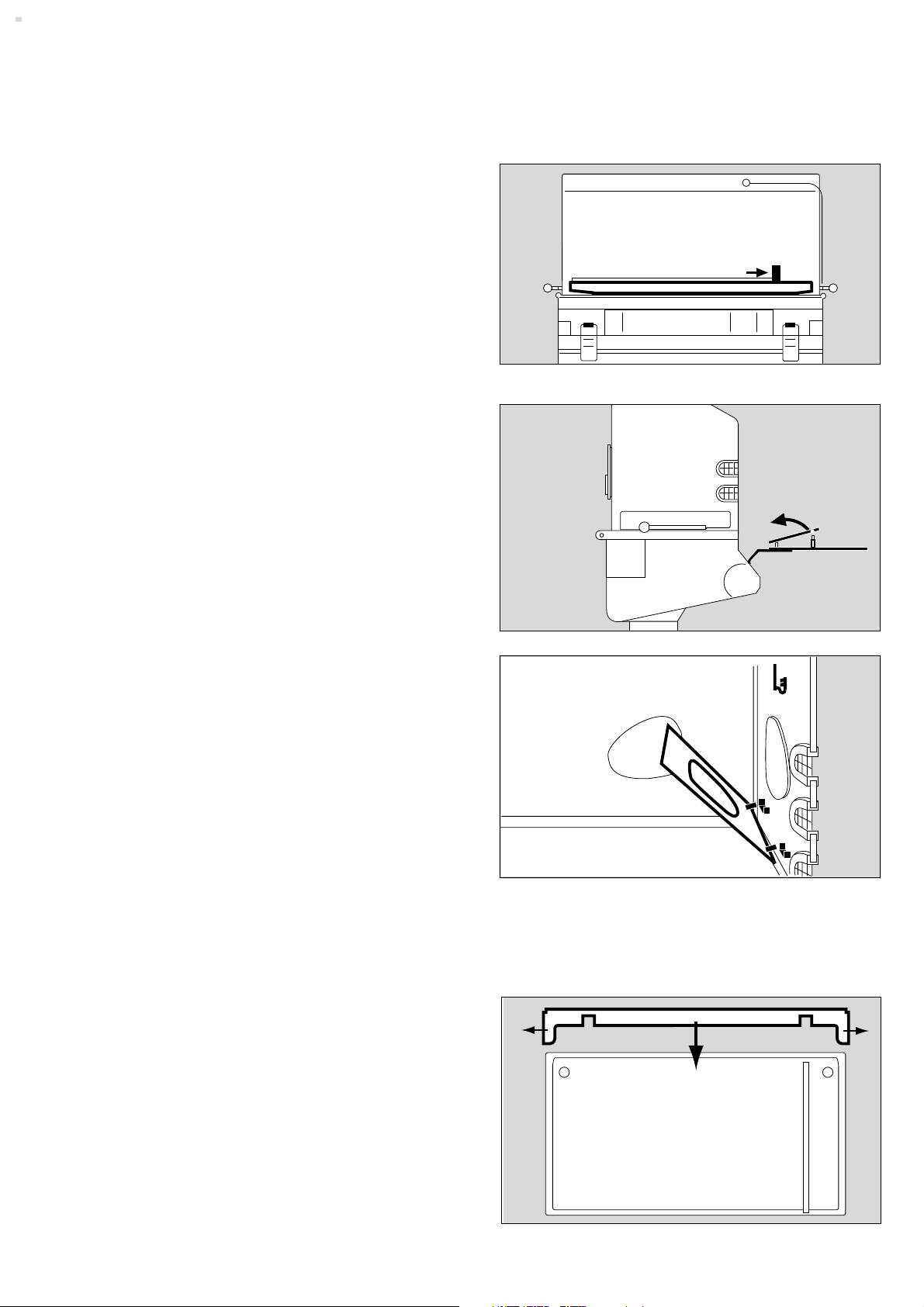
Re-positioning bed end
Can be used at right or left end of bed, as required.
● Open front door.
Preparation
Doors, ports and bed
1 Push middle of bed end outwards until it is released
from the groove and
● re-position at other end of bed.
● Close front door.
Double wall on front door
e. g. when cleaning the incubator
● Open front door.
2 Disengage double wall from upper bracket and
remove.
● After cleaning refit the double wall by gently pushing
back until it engages again; close the front door.
Removable double walls, optional
When older children are being treated, heat production is
greater and the temperature in the incubator may become
too high – the double walls should then be removed.
D
1
Incubator 8000 NC
2
To remove:
● Disengage double wall from upper bracket and
remove.
To put back:
● Open front door.
● Fit double wall to clips provided, raise and
● engage in upper bracket.
● Close front door.
Bed extension
Required when the rear double wall is not being used
to reduce risk of patient being trapped.
● Open front door and pull out bed.
3 Push both ends of bed extension out slightly and
4 click on the rear side of the bed.
Make sure that the bed extension is securely atteched.
● Replace bed in incubator.
3
4
3
Do not use bed extension when the rear double wall is in
place as the incubator temperature may be affected.
7
Page 8

Preparation
Connecting air-temperature sensor
Accessories
Connecting air temperature sensor
● Push air temperature sensor plug through slot in the
incubator housing, from below and
1 push into socket until it engages.
2 Route sensor cable through cable clips.
Fitting accessories
Support for ventilation hoses
● Fold down front door.
● Raise bed and lift out of incubator.
● Push mattress to one side a little.
Push hose support into appropriate hole, right or left.
● Screw knurled screws on from below and tighten.
2
2
1
● Replace bed in the incubator and close front door.
Fitting rail
Rail is used to hold
Bronchial suction equipment
Instrument tray
Mounting plate for ancillary equipment
Infusion stand
Oxygen therapy equipment
● Screw rail to left or right side of housing with Allen
screws.
Maximum load must not exceed 25 kg.
8
Page 9
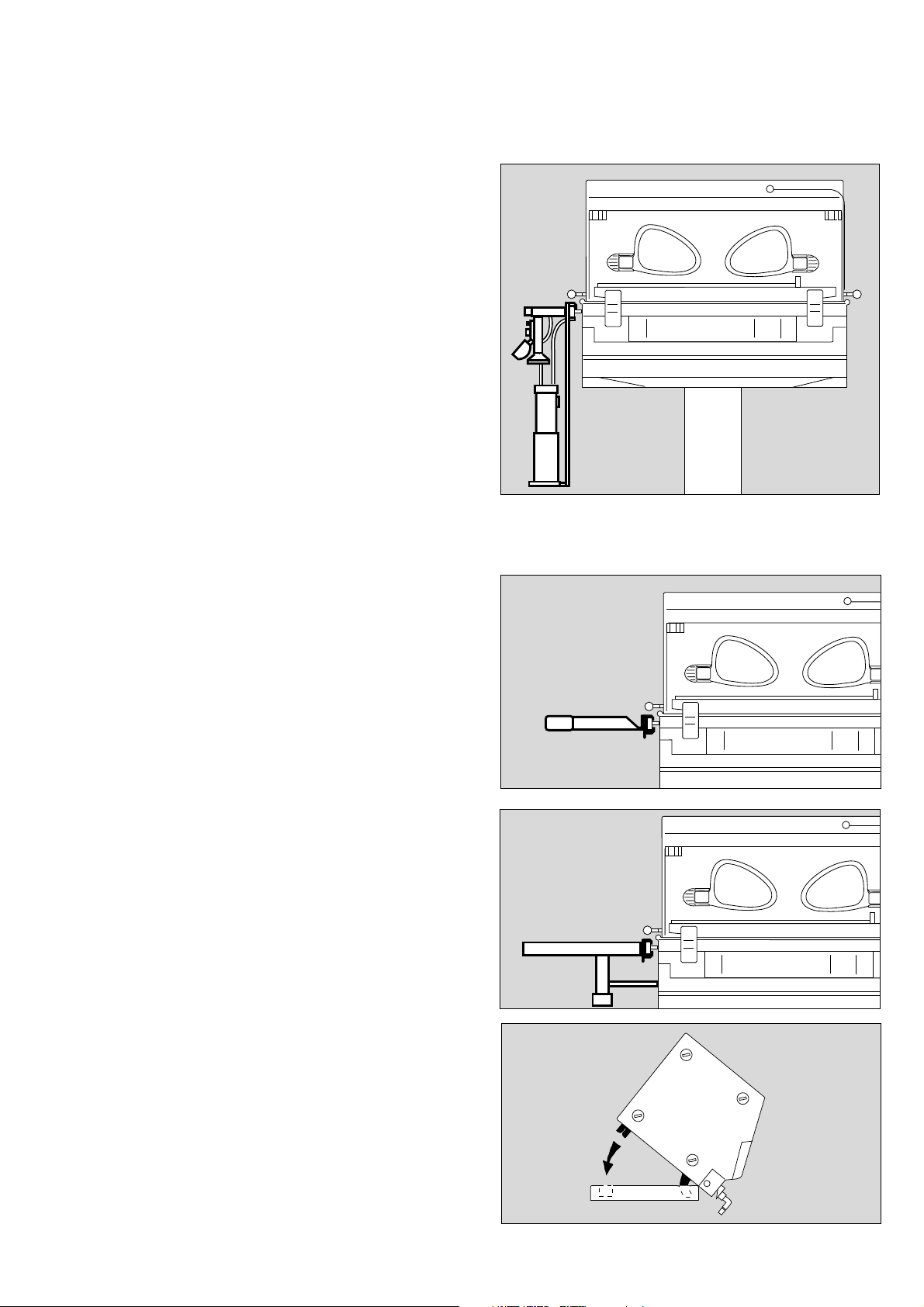
Bronchial suction equipment
See also relevant Instructions for Use.
To mount on incubator
● Attach holder to one of the rails using rail clamp.
● Hang cylinder holder on it.
● Attach ejector to rail with rail clamp.
Preparation
Accessories
● Connect hose.
Instrument tray
(for small items)
● Attach tray to rail and tighten clamp. Maximum load
must not exceed 2 kg.
D
Incubator 8000 NC
D
Incubator 8000 NC
Mounting plate
For monitor and ventilator with latching system for
standard Dräger housings 1/2 B, e. g.
Dräger Babylog 8000.
Maximum load must not exceed 20 kg.
● Attach plate to rail and tighten clamp.
Fixing equipment to mounting plate
Example: Dräger Babylog 8000
● Remove foot strips from Babylog.
● Tilt Babylog forward by about 45°.
1 Insert front latches into slots in mounting plate.
2 Lower Babylog, insert the rear latches into slots in
mounting plate and secure at back with knurled
screws.
D
Incubator 8000 NC
2
1
9
Page 10
Preparation
Accessories
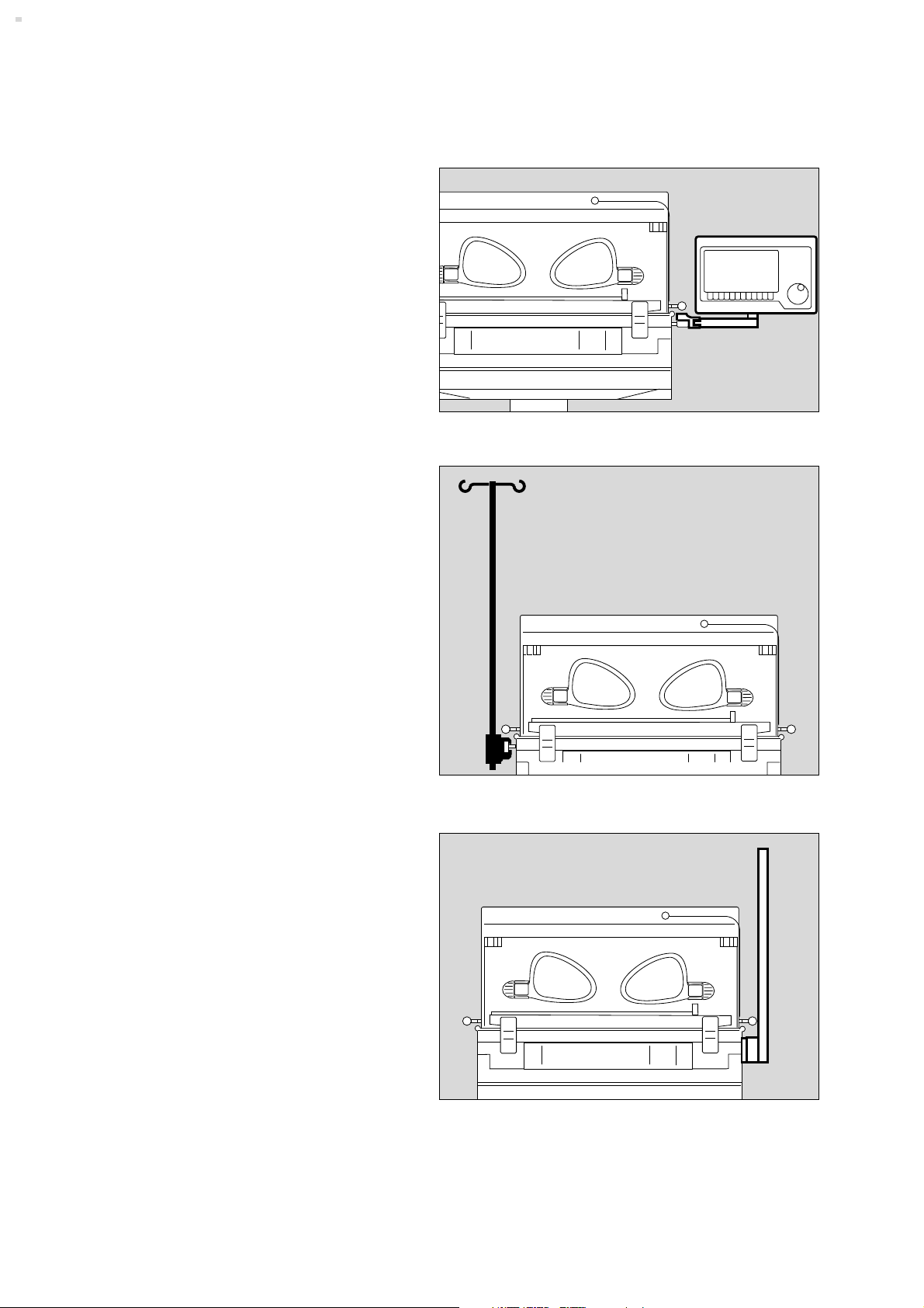
BabyScreen
Optional for ThermoMonitoring
● Attach holder to rail.
● Engage BabyScreen in holder.
● Follow relevant assembly instructions.
D
Infusion stand
● Attach stand to rail with rail clamp and tighten.
D
Incubator 8000 NC
Fitting pillar
● Screw pillar to left or right of housing, as required.
● Secure pillar with allen screw.
10
D
Incubator 8000 NC
Page 11

Attaching infusion bottle holder to pillar
● Attach clamp for infusion bottle holder to pillar and
tighten using tommy screw.
Preparation
Accessories
Swivel table
For small items, maximum load = 3 kg
● Attach clamp on swivel table to pillar and tighten
screw. Make sure that swivelling area is clear.
Swivel cupboard, optional
To fit a swivel cupboard:
D
D
Incubator 8000 NC
Incubator 8000 NC
● Push Allen screw up through unit from below and
screw firmly to unit mounting.
● Insert extra drawers.
● Store whatever is needed in them.
The maximum load on the incubator must not
exceed 25 kg.
D
Incubator 8000 NC
11
Page 12
Preparation
Preparing oxygen therapy accessories
Preparing oxygen therapy accessories
– for oxygen enrichment of incubator air
– for oxygen enrichment using a head box
● Follow Instructions for Use of equipment used.
● Monitor O2 concentration
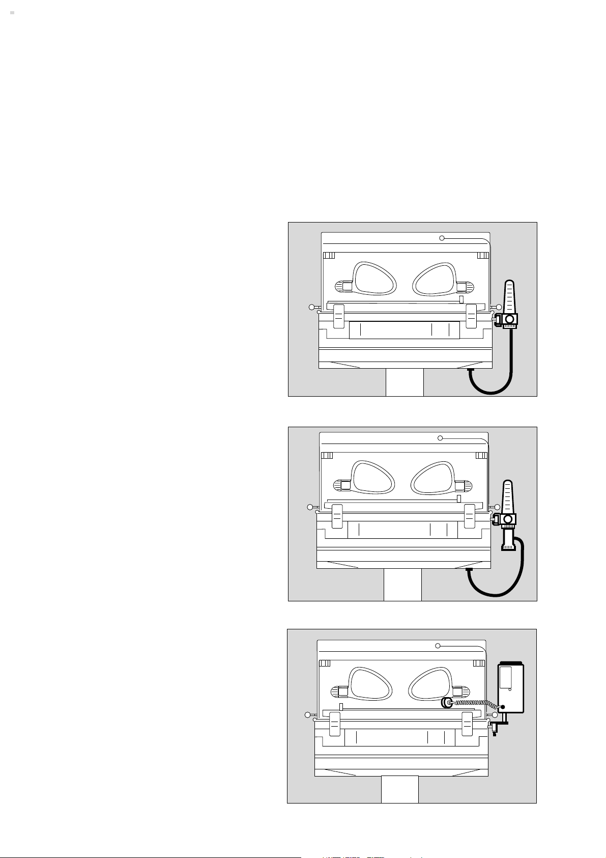
O2 flowmeter
● Attach O2 flowmeter to rail.
● Fit hose to connector on O2 flowmeter and
● to O2 connection underneath incubator.
● Push probe on O2 connecting hose into terminal unit,
only as far as "parking position" initially.
Oxygen limiter
If an oxygen limiter is going to be used:
● Unscrew connector on O2 flowmeter and screw
oxygen limiter on.
● Connect hose.
O2 meter
D
D
Incubator 8000 NC
Incubator 8000 NC
Monitor O2 concentration with O2 meter which has alarm
limits, e. g. Dräger Oxydig:
● Attach O2 Oxydig meter to rail with meter bracket.
● Place sensor capsule in incubator.
● Route sensor cable through one of the flexible hose
seals. Push sensor plug into socket on Oxydig until it
clicks into place.
12
D
Incubator 8000 NC
Page 13

Oxygen distributor
● Attach oxygen distributor, order no. 2M 18 810, to
rail.
Preparation
Oxygen therapy accessories
Cables and hoses
Routing cables and hoses
● Route hoses and cables through the flexible hose
seals.
D
Incubator 8000 NC
● Push ventilation hoses and cables into clip at end of
hose support.
13
Page 14

Checking Readiness for Operation
Before using for the first time
Before each use
Checking Readiness for Operation
Before using for the first time
● Check that the mains voltage corresponds to the
specification on the rating plate.
Before each use
● Check that the equipment has been disinfected.
● Check that the calibration seals on the front of the
equipment and on the skin temperature sensor are still
valid (only required in Germany).
● Check that an adequate gas supply is available for the
equipment to be used.
● Check that the accessories and therapy equipment
required are to hand and in perfect condition.
Check readiness for operation in accordance with
relevant Instructions for Use.
● Check that the incubator canopy has no cracks or
sharp, chipped edges.
● Check that the hinges and pivots on the canopy are in
proper working order.
● Check that the cables and hoses are routed correctly
and safely.
● If the rear double wall has been removed: Check that
the bed extension is provided. See page 7.
● Connect to mains power supply.
Do not use a mains distribution board.
[
If there is a protective circuit breaker in the supply
to the mains distribution board, the permitted limit
value for leakage currents might be exceeded.
There could then be an electrical risk for patient
and staff.
14
Page 15

Checking that hand ports will stay closed
● Open each hand port and then close carefully until
catch engages.
Checking Readiness for Operation
Before each use
1 Grip rim of closed hand port and pull outwards – it
should not open.
If the hand port does not remain engaged:
● Call DrägerService.
Checking that front door will stay closed
● Open front door.
● Lift up front door again.
2 Squeeze catches together on both sides, push front
door forward and release catches. Push firmly on
front door to ensure that catches fully engage. Red
mark on catches should no longer be visible.
If the front door does not engage:
● Call DrägerService.
Checking air filter
3 Open filter cover plate downwards.
If a filter is fitted:
● Remove filter and check fitting date; label is on edge
of filter.
1
22
If filter is more than 2 months old:
● Replace with a new filter.
● Write fitting date on new filter label and stick to edge
of filter.
● Press filter firmly into the seal.
Make sure that the direction of flow through filter is
correct. Arrow on filter has to point into incubator.
● Close cover plate.
Testing tilting mechanism for bed
4 Raise left end of bed to maximum height.
5 Push down on raised bed with hand – bed must not
drop down.
If bed does drop down:
● Call DrägerService.
● Check tilting mechanism at right end of bed in the
same way.
3
5
4
3
4
D
Incubator 8000 NC
15
Page 16

Checking Readiness for Operation
Before each use
Activating incubator self-test
1 Push on/off switch in – until it engages = on.
Functioning of incubator is self-tested.
2 Green LED is lit.
3 Display of actual values shows dashes.
If Err is displayed = error, see p. 39 to 41.
Checking mains power failure alarm and NiCd batteries
● Disconnect from mains.
4 Red N LED is lit. Continuous sound commences.
The volume should remain constant for at least
30 seconds.
If the volume decreases too soon:
● Leave incubator connected to mains and switched on
for 24 hours for the NiCd battery to be charged.
°C HAUT/SKIN/PEAU/PIEL °C LUFT/AIR
15.22
87.06
Control
°C
3
±1,5 °C
Sensor
°C
Reset
°C
± 0,5 °C
Sensor
3
°C
Check
36 °C
±0,1
°C LUFT/AIR
°C
>37 °C
Control
Reset
Control
>37 °C
>37 °C
Control
Check
Inop.Control
2
Check
1
4
● Repeat check.
If volume decreases too soon again:
● Call DrägerService.
Checking LEDs, displays and alarm sound
5 Press k key:
For about 2 seconds – all LEDs are lit (except the
mains power failure LED), the digital displays show
88.8 and alarm sound commences.
Thereafter, displays and LEDs go dark and alarm
sound ceases. After approximately another 2 seconds
the original displays for measured and set values reappear.
This check may also be carried out during operation.
● Check at least once daily.
If there is a fault:
Call DrägerService.
°C LUFT/AIR
°C
Reset
>37 °C
Control
Check
5
The incubator is ready for operation when all
checks have been carried out successfully.
16
Page 17

Operation
Precautions
Operation
Precautions
Warming-up time
Allow adequate time for warming-up before placing the
baby in the incubator (about 35 minutes).
Recommendation: operate incubator in standby,
see p. 19.
Do not cover air stream channels in base plate:
Danger of burning or cooling patient.
Controlling temperature of incubator
– Temperature may be increased very rapidly when
required because of high heating power.
– Temperature drops slowly because of good thermal
insulation.
Additional external heat sources, such as sunlight, heat
lamps, spotlamps, electric cushions should be avoided.
These increase the air temperature inside the incubator in
an uncontrolled manner.
Setting air temperature of incubator
The baby experiences minimal heat loss
– by convection because of low air speed across bed
– by conduction through the mattress
– by evaporation because of high humidity setting in
incubator.
Therefore,
compared with other incubators, such as the Incubator
6000 or 7000, a lower incubator air temperature can be
set.
The baby's core temperature must be monitored
continually, particularly during the first few hours of
incubator care.
17
Page 18

Operation
Precautions
Reducing the internal temperature of the incubator
The cooling time is dependent on the design and can be
accelerated by:
– reducing the outside temperature (when possible)
– reducing the air-humidity setting.
The rate of cooling is not accelerated by:
– setting the air temperature to a lower value than is
actually required.
In urgent cases: open front door or hand ports. When
front door is opened, there must be continuous
supervision to make sure that the baby does not fall out.
Fire risk from oxygen
– No naked lights or smoking. Textiles, oil and plastics
can very easily catch fire and burn rapidly in an
oxygen-enriched atmosphere.
– Keep all fittings and seals in contact with oxygen free
of oil and grease.
– Open valves on O2 cylinders slowly.
– Do not use an incubator where there are flammable
anaesthetic gases or disinfection agents.
Risk of explosion.
Phototherapy in the incubator
Absorption of light through the baby's skin will supply
heat which may increase the baby's core temperature.
Therefore,
● Decrease temperature setting for incubator air by
about 2 °C 15 minutes before phototherapy.
● Decrease the set value for humidity.
● Reduce the room temperature to at least 3 °C below
the air temperature of the incubator.
This value applies for Dräger 800/8000/4000
phototherapy units.
Other phototherapy units, particularly those without a
built-in fan, may cause even greater heating of the
incubator.
The core temperature of the baby must be monitored
with particular care during phototherapy.
The supply of fluids to the baby must be increased
e.g. by parenteral infusion, in order to compensate for
increased loss of water during phototherapy.
The phototherapy lamp and incubator canopy must
not be covered with cloths, aluminium foil, or other
materials, to boost the photo-therapeutic effect.
Risk of heat build-up. The incubator could not then be
adequately cooled with ambient air.
Danger of overheating the patient.
– Do not use or keep flammable liquids, such as
alcohol, ether and acetone in the incubator.
– Do not use any electrical equipment inside the
incubator, except, that is, for equipment expressly
designed for use in areas where there is a risk of
explosion.
Physiological risks from oxygen
The air in the incubator should only be enriched with
oxygen when prescribed by a doctor. It is absolutely
essential that such oxygen enrichment is controlled
on the basis of the arterially-measured oxygen partial
pressure in the blood of the patient. This is the only
way of avoiding both hyperoxaemia (damage to the
eyes) and hypoxaemia (damage to the brain).
Temperature of breathing gas
During ventilation the breathing-gas hoses may become
too warm from the heated air circulating in the incubator.
The temperature of the breathing gas must be monitored.
Preventing high noise levels
Noise levels that are too high for the patient may be
caused by:
– using head boxes to deliver pressurised gas,
– wear on the bearings of the fan motor,
– placing objects on the incubator canopy.
● Observe maintenance intervals, p. 42.
● Do not place anything on the incubator canopy.
Electrical safety
Use only electro-medical ancillary equipment which
complies with the IEC 601-1, EN 60601-1 or DIN
VDE 0750, part 1, regulations.
18
Page 19

Wait for warming-up time.
Wait for about 35 minutes before use.
● Heat incubator in "air temperature control" operating
mode.
If incubator has to be used urgently:
● Operate incubator in standby mode:
Set air temperature to 32 °C to 36 °C,
see p. 20, and set humidity control to 0, see p. 30.
Just before placing the baby in the incubator:
Fill water container
Operation
● If required use protective gloves.
1 Take cover of water container off and
2 fill container to mark with clean, distilled or
demineralised water (hospital dispensary).
Do not use any additives.
Take care not to overfill.
● Put cover of water container back.
● Then disinfect hands.
If water bottles are used:
Fill water bottles
● If required use protective gloves.
1 Open back panel and fold down.
2 Disconnect empty water bottles and refill with 500 mL
clean, distilled or demineralised water (hospital
dispensary). Do not use any additives.
● Refit filled water bottles and close back panel
again.
● Then disinfect hands.
1
2
1
2
Placing baby in the incubator
● Open front door and pull out bed.
● Put the baby on the bed and slide the bed back in
position.
● Close the front door and check that the catches are
properly engaged.
● Adjust the bed as required.
19
Page 20

Operation
Controlling air temperature
Controlling air temperature
Measure the patient's core temperature at regular
intervals.
1 Push on/off switch in – until it engages = on.
2 Green LED is lit.
● Wait for self-test to finish, then incubator will switch to
"air temperature control" mode.
3 The display alternates regularly between measured
value for air temperature and the word, SEt.
4 Default value for flashing display of air temperature set
value is 33.0 °C.
°C LUFT/AIR
3
°C
4
Reset
>37 °C
Control
Check
1
2
5 Press P or p key briefly to select this set value.
The display will remain continuously lit.
Setting values in 28 °C to 37 °C range
The set value can be changed in 0.1 °C steps.
6 Press p key – the set value is decreased,
7 Press P key – the set value is increased.
°C LUFT/AIR
5
°C LUFT/AIR
°C
5
Reset
>37 °C
Control
Check
8
● Press P or p key until the set value required is
reached.
8 While green R LED flashes – incubator is in heating-
up phase.
20
°C
6
7
Reset
>37 °C
Control
Check
Page 21

Extending range of set values from 37 °C to 39 °C
Only do this if prescribed by a doctor.
The patient's core temperature must be monitored
very carefully.
1 Press unlocking key 7,
2 yellow >37 °C control LED is lit.
Operation
Controlling air temperature
The alarm limit for high temperature will be increased
from 38 °C to 40 °C.
3 Keep P or p key pressed until the value required is
displayed.
● Set a value between 37 °C and 39 °C within
1 minute.
Otherwise:
– >37 °C control LED will go out.
The lock against setting a higher range of values will
be in force again.
The alarm limit for high temperature will return to
38 °C again.
If a value below 37 °C is set after the range of values has
been extended:
– the extension is automatically cancelled.
If the actual temperature remains above 38 °C, the high
temperature alarm is triggered.
°C LUFT/AIR
3
2
°C
3
Reset
>37 °C
Control
1
Check
Recommendation to prevent an high temperature alarm:
● Set value to 37.1 °C and wait until incubator has
cooled to 37.9 °C,
● then set value below 37 °C, as required.
21
Page 22

Operation
Controlling air temperature
Alarms
Alarms
Central alarm
1 Red Alarm LED flashes, and an appropriate alarm
sound commences.
Alarms with intermittent tone may be suppressed for
10 minutes:
2 Press G key,
3 yellow
LED and
g
1 red Alarm LED are lit.
If there is a deviation of more than ±1.5 °C between set
value for air temperature and measured value:
● Red Alarm LED and
4 red ±1.5 °C LED flashes,
5 display flashes and intermittent tone commences. The
intermittent tone may be suppressed for 10 minutes:
°C LUFT/AIR
°C LUFT/AIR
5
1
3
2
°C
°C
Reset
>37 °C
Control
>37 °C
Check
2
3
When measured value is again within ±1.5 °C of
temperature set,
● ±1.5 °C LED and Alarm LED go out.
The intermittent tone ceases.
When the incubator is switched on the alarm sound is
automatically suppressed for 30 minutes during the
warming-up phase:
4 red ±1.5 °C LED and
● yellow
LED and red Alarm LED are lit.
g
If the air temperature is above 38 °C, or above 40 °C
for extended range of values,
● red Alarm LED and
6 red T LED flash.
7 Display flashes and intermittent tone commences. The
alarm sound may be suppressed for 10 minutes.
When the air temperature has fallen below the alarm limit
again:
8 Press ƒ key, the alarm is cancelled.
For other alarms, see "Fault, Cause, Remedy",
p. 38 and 39.
4
7
°C LUFT/AIR
6
Reset
Control
°C
Reset
>37 °C
Control
Check
Check
8
22
Page 23

When there is a "skin temperature control" module installed
and it is in operation, the "air temperature control" mode
can be switched on again:
1 Press ç key,
2 green Control LED is lit.
°C LUFT/AIR
Operation
Using skin temperature control
2
The "air temperature control" mode is re-activated.
The set value for air temperature will be the last value
determined by the system.
Using skin temperature control
When the skin temperature control option is installed.
Do not use on babies in shock as their skin temperature
is well below normal. Using skin temperature control
would increase the temperature of the incubator too
much.
To control air temperature, see p. 20.
Core temperature must be measured regularly.
°C
Reset
>37 °C
Control
Check
1
23
Page 24

Operation
Using skin temperature control
Connecting skin temperature sensor
1 Insert yellow sensor plug into the yellow socket on left
side of housing.
2 Route sensor cable through one of the flexible hose
seals in the canopy.
3 Remove protective foil from adhesive pad and place
skin temperature sensor on pad.
● Using the adhesive pad, attach sensor tip to the
infant's skin where the temperature is to be
measured.
● Keep sensor cable in place with adhesive plaster.
Placing sensor
2
3
1
If the baby is lying on its back:
● Attach sensor to the abdomen in the region of the
liver.
If the baby is lying on its stomach:
● Attach the sensor to the back in the region of the
kidneys.
The sensor must never be attached under the baby
since it would then be measuring and controlling core
temperature and not skin temperature.
● Check regularly that the skin temperature sensor
is properly fixed to the baby's skin.
A skin temperature sensor which has fallen off would
be measuring air temperature so that the baby could
become overheated (though the temperature of the air
in the incubator would not exceed 39 °C).
● Do not use skin temperature sensors to measure
rectal temperature.
When a skin temperature sensor is attached but the "air
temperature control" mode is in operation, the measured
skin temperature is displayed.
Skin temperature is not then being controlled.
24
°C HAUT/SKIN/PEAU/PIEL °C LUFT/AIR
°C °C
Check
Control
36 °C
±0,1
Reset
>37 °C
Control
Page 25

When the temperature falls outside the 30 °C to 42 °C
measuring range:
Operation
Using skin temperature control
– 3 dashes in the bottom of the display =
temperature below 30 °C
– 3 dashes in the top of the display =
temperature above 42 °C
● see "Fault, Cause, Remedy" section, p. 40.
Activating skin temperature control
Allow at least 5 minutes for the skin temperature
sensor to reach the baby's temperature.
When value displayed remains constant,
1 Press ç key,
2 green Control LED is lit,
skin temperature control is in operation.
3 The display alternates between measured value of
skin temperature and the word SEt.
4 Flashing display of set value for skin temperature.
5 The measured value for air temperature continues to
be displayed.
°C
°C
°C HAUT/SKIN/PEAU/PIEL °C LUFT/AIR
2
3
°C °C
4
Check
36 °C
±0,1
5
1
Reset
>37 °C
Control
The incubator offers an appropriate value, depending on
the situation.
Situation Set value
Set value for air temperature not confirmed; 36.3 °C
Faulty or disconnected sensor
Actual skin temperature below 35 °C when 35 °C
switching over
Actual skin temperature between 35 °C actual skin
and 37 °C when switching over temperature
selected
Actual skin temperature above 37 °C
37 °C when switching over
Confirming set value:
6 Press P or p key briefly, the display remains
continuously lit.
°C HAUT/SKIN/PEAU/PIEL °C LUFT/AIR
°C °C
>37 °C
6 6
Check
36 °C
±0,1
Control
Reset
Control
25
Page 26

Operation
Using skin temperature control
Setting values in 35 °C to 37 °C range
1 Press P or p key until the set value required is
displayed.
°C HAUT/SKIN/PEAU/PIEL °C LUFT/AIR
Time needed for control to be effective
Differences between the set value and the actual value
for skin temperature are corrected by the temperature of
the air in the incubator which is between a minimum of
28 °C and a maximum of 39 °C.
When the skin temperature required is higher than the
actual temperature (skin too cold), air temperature in the
incubator is increased.
When the skin temperature required is lower than the
actual temperature (skin too warm), the air temperature in
the incubator is decreased.
The length of time during which there is a difference
between the set value and actual value of skin
temperature also has an influence on the control of air
temperature inside the incubator.
°C °C
1 1
Check
36 °C
±0,1
Control
skin temperature air temperature
set value
actual value
controls
skin temperature air temperature
actual value
set value
controls
Reset
>37 °C
Control
The patient's skin temperature can change suddenly, as
a result of feeding or being handled, for instance, so that
deviations of a few tenths of a degree are quite normal.
Therefore:
The value set for skin temperature should not be
changed unless the core temperature needs to be
corrected.
Check functioning during operation:
2 Press 6 key – the simulated temperature value
should be 36 ±0.1 °C.
Check daily.
°C HAUT/SKIN/PEAU/PIEL °C LUFT/AIR
°C °C
Check
Control
36 °C
2
±0,1
Reset
>37 °C
Control
26
Page 27

Alarms
For deviations greater than ±0.5 °C between set value
and actual value of skin temperature:
1 Red Alarm LED and
2 Red ±0.5 °C LED flash,
Using skin temperature control
°C HAUT/SKIN/PEAU/PIEL °C LUFT/AIR
Operation
Alarms
1
3 display flashes and intermittent tone commences.
The intermittent tone can be suppressed for 10 minutes:
4 Press G key.
5 Yellow g LED and red Alarm LED are lit.
When measured value is within ±0.5 °C of the set value
again,
2 ±0.5 °C LED and
1 red Alarm LED go out.
intermittent tone ceases.
5 Yellow g LED goes out.
If the sensor plug is disconnected or sensor is faulty:
6 Display of 3 dashes in centre of display.
After 15 seconds:
● Intermittent tone commences.
6 Display of 3 flashing dashes in centre of display.
°C
3
°C
2
°C HAUT/SKIN/PEAU/PIEL °C LUFT/AIR
°C
Check
Control
36 °C
±0,1
6
°C
°C
°C
5
°C
Reset
>37 °C
Control
4
Check
7
°C
>37 °C
7 Red Alarm LED and
8 red Sensor alarm LED are lit.
Then:
● Connect sensor without delay or replace skin
temperature sensor.
The intermittent tone can be suppressed for 10 minutes:
● Press G key, yellow
LED and
g
red Alarm LED are lit.
Check
Control
36 °C
8
±0,1
Reset
Control
Check
27
Page 28

Operation
Using skin temperature control
ThermoMonitoring
ThermoMonitoring, optional
For a better diagnosis of the child's thermal condition, it
is recommended that the temperature is measured both
centrally and peripherally. Both temperature measurements
may be displayed graphically via a Windows-PC or a
Dräger BabyScreen to document both the progress of
therapy for the child and the therapy itself.
Incubator must have:
– Second socket for peripheral skin temperature
sensor.
– Operator panel with © key
– BabyLink interface and MediCable connecting cable
(optional).
ThermoMonitoring data may be displayed on:
– Babyguard 8000 patient monitor
– BabyScreen (optional)
– Windows PC with ThermoView programme (optional).
Follow relevant Assembly and Operating Instructions.
Connecting peripheral skin temperature sensor
1 Connect white peripheral skin temperature sensor to
white bottom socket on left wall of housing.
2 Route sensor cable through one of hose seals.
3 Remove protective foil from adhesive pad and place
skin temperature sensor on pad.
● Attach sensor to patient's extremeties, preferably on
foot, using adhesive pad.
● Fix sensor cable in place with adhesive plaster.
● Connect Windows-PC or BabyScreen to serial
BabyLink interface using MediCable.
Follow relevant Instructions for Use.
Displaying measured values from peripheral skin
temperature sensor
4 Press © key and keep pressed. Yellow LED in key is
lit.
5 Peripheral skin temperature is displayed.
4 Release © key,
5 skin temperature recorded close to core by first skin
temperature sensor is displayed again.
If 3 dashes appear in the display, see p. 25.
The measured value of the peripheral temperature does
not affect the control of the temperature in the incubator.
Both in air temperature and skin temperature mode the
peripheral skin temperature sensor can be disconnected.
No alarm will be given.
Both skin temperatures can be displayed and requested
when the incubator is operating in the air temperature
mode.
3
°C HAUT/SKIN/PEAU/PIEL °C LUFT/AIR
°C
5
°C
Check
Control
36 °C
±0,1
°C
4
2
1
°C
Reset
>37 °C
Control
Check
28
Page 29

Using humidity control
Air temperature and relative air humidity are
interdependent. If the air temperature in the incubator is
changed, the incubator adjusts the output of the
humidifier to suit the changed temperature conditions so
that the relative air humidity required remains constant.
Up to 85 % relative humidity can be achieved.
Line A
Typical ambient conditions found in neonatal intensive
care units.
(normal conditions: room temperature, 25 °C to 28 °C,
relative humidity, about 30 %)
Line B
During low air humidity or when dry oxygen is supplied
the linemoves down the light grey range, (e. g. relative
humidity 60 %, heat level 6 to 7)
Line C
When ambient air humidity is greater than 30 %, the line
moves down the dark grey range, (e. g. relative
humidity 60 %, heat level 1 to 3)
required
rel. humidity
in %
(max. 85%)
60
CAB
80
70
50
40
30
20
10
01 2345678910
humidifier
switched off
Operation
Controlling humidity
heat level
Recommended air humidity for neonates:
Gestation week Recommended relative humidity
up to 32nd week as high as possible
from 32nd week about 50 %
to end of therapy
Example:
60 % humidity required.
For normal conditions (line A),
1 Set heat level to »5«, see page 30.
Under normal conditions, if heat level 7 or above is set,
condensation may occur on the incubator walls.
Then:
● Decrease heat level by one level.
°C FEUCHTE/HUMID.
1
29
Page 30

Operation
Controlling humidity
When incubator is switched on:
1 »0« flashes is display – humidity control = off.
2 Press P or p key briefly – to confirm off,
»0« remains continuously lit in the display.
Changing set value for humidity:
3 Press P key – set value is increased in steps from
0 to 10.
4 Press p key – set value is decreased in steps from
10 to 0 (0 = OFF).
°C FEUCHTE/HUMID.
2
2
1
°C FEUCHTE/HUMID.
34
34
Alarm for water shortage:
5 Red Alarm LED flashes,
6 red H2O LED and
7 display flash.
Intermittent tone commences.
● Replenish water supply, see p. 19.
The intermittent tone can be suppressed for 10 minutes:
8 Press G key,
9 yellow LED is lit.
°C FEUCHTE/HUMID.
7
6
°C LUFT/AIR
5
Check
9
°C
Reset
>37 °C
Control
8
Check
30
Page 31

Supplying oxygen
Caution: physiological risks from oxygen
The air in the incubator should only be enriched with
oxygen if prescribed by a doctor. Oxygen enrichment
should be controlled on the basis of the arteriallymeasured oxygen partial pressure in the blood of the
patient. This is the only way in which both
hyperoxaemia (damage to the eyes) and hypoxaemia
(damage to the brain) can be prevented.
● Monitor O2 concentration in incubator.
Use O2 monitor, such as Dräger-Oxydig.
Preparation, p. 12.
● Supply oxygen from a medical gas pipeline system via
an O2 flowmeter – push probe in fully.
Operation
Supplying oxygen
● Preparation, p. 12.
● When concentration required is reached, switch off
O2 supply at flowmeter.
Recommended set values:
O2 concentration
Vol.% (approx.)
25 30 35 40 45 50 55 60
O2 flow
L/min
1.5 3.5 5.5 7.5 9 11 13 15
Using oxygen limiter
● Preparation, p. 12.
The handwheel of the O2 limiter has 2 settings.
Red setting: no limitation of O2 supply.
D
Incubator 8000 NC
White setting: O2 supply limited to 6 L/min =
O2 concentration about 40 vol.%,
with O2 flow valve fully open.
If a lower O2 concentration is required,
set O2 supply to less than 6 L/min.
● Set handwheel as required.
D
Incubator 8000 NC
31
Page 32

Operation
Baby scales
Vacuum mattress
Using electronic baby scales
Accessory
1 Set bed at maximum height with both levers.
● Open and then lower front door.
2 Slide the electronic scales under bed as far as
possible. Guide scales along ridges on base plate.
Rail carrying display unit passes through the lower
hose seal.
● Close front door again and lower bed to its lowest
setting.
● Weigh baby, following Instructions for Use for
Seca Inscale Baby Scales.
After weighing:
● Take scales out in reverse order
or
● Scales may remain in incubator.
Bed can be tilted, as before.
1
D
Incubator 8000 NC
1
2
D
Incubator 8000 NC
Using vacuum mattress
Accessory
The mattress can be formed into any shape, and will
keep this shape after the mattress has been evacuated.
In this way babies can be supported in extreme positions
for special treatment. The standard mattress may also
remain inside the incubator.
● Open and then lower front door.
● Place mattress inside and form it into approximately
the shape required.
● Place baby on mattress and "mould" mattress around
baby.
● Connect hose of suction unit to vacuum mattress.
Open valve and evacuate vacuum mattress.
● Close valve and remove hose.
● Close front door.
32
Page 33

Using phototherapy unit 800/8000/4000
Accessory
Follow relevant Instructions for Use.
● Push trolley carrying phototherapy unit under incu-
bator or in the case of Photo-Therapy 4000 can also
be placed directly on top of the canopy.
● Adjust height:
Minimum distance between bottom of phototherapy
unit and patient is:
0.4 m for Photo-Therapy 800/8000
0.3 m for Photo-Therapy 4000
If the height of the bed is changed later, make
sure that this minimum clearance is still
maintained.
Exampel: Photo-Therapy 4000
Fuse
7
Operation
Phototherapy
Interface
mindestens 0,3 m
minimum 0.3 m
● Follow safety advice, see p.18.
Using "BabyLink Incubator" interface
(optional)
The "Babylink Incubator" interface provides incubator
data (actual values, set values, alarms) via a serial
interface.
At present, measured values can be displayed as trends
on the Dräger Babyguard 8000 Paediatric Monitor.
Other possible connections are the Dräger BabyScreen
or any Windows-PC which can run the ThermoView
program.
The interface protocol is included in the BabyLink
modification set (82 90 607).
Follow Instructions for Use for interface.
33
Page 34

Care
Stripping down
Care
Clean and disinfect incubator thoroughly:
– after each change of patient
– at least once a week.
With septic patients:
– disinfect seals on hand ports daily.
Clean and disinfect the accessories, such as the suction
equipment, the flowmeter and the skin temperature
sensor in accordance with the relevant Instructions for
Use.
Stripping down
● Switch off incubator. Disconnect from mains and
disconnect the medical gas supply.
● Remove all accessories.
Emptying the water container/water bottles: Risk of
microbial contamination
Observing hospital hygiene regulations.
Water container:
● Remove cover from water container.
1 Remove container from holder by lifting it up. Drain
water, observing hospital hygiene regulations.
● Hold hose by cuff and detach from connector on
heater.
Water bottles:
● Fold down back panel.
● Allow water to flow back into bottles.
1 Remove bottles from holder and drain,
● Hold connecting hose by cuff and detach from
connector on heater.
● Unscrew bottle holder.
2 Open hand port, remove seals from hand port
openings and close hand port again.
1
1
2
When skin temperature control option has been used:
● Disconnect skin temperature sensor.
● Remove skin temperature sensor from inside
incubator.
3 Remove all hose seals.
4 Tilt canopy back as far as it goes.
34
3
4
Page 35

Care
Stripping down
Cleaning/disinfecting/sterilizing
1 Remove mattress from bed.
2 Lift off bed. Undo screw on ventilator hose support
and remove hose support. Remove bed extension.
3 Pull both support brackets up and out.
4 Remove base plate
Caution. Be careful not to burn yourself
The risk of burns from the heater is particularly great
when the incubator has been closed and this risk remains
for a long time after the unit has been switched off. (It
takes about one hour for the temperature to fall to 70 °C).
5 Remove fan.
6 Remove trough.
1
2
33
4
5
6
Cleaning/disinfecting/sterilizing
For users in the Federal Republic of Germany we recommend that only disinfectants on the current DGHM
(DGHM: German Society for Hygiene and Microbiology)
list of surface disinfectants are used.
For medical and hygienic reasons, disinfectants based on
quaternary compounds should be used.
Damage may occur to the material of the incubator, particularly to the sensetive covering parts (PMMA/plexiglass
and PC/polycarbonate), if preparations are used which
are based on
– chlorine-releasing compounds
– organic and inorganic acids
– alcohols.
With regard to material compatibility we recommend the
following surface disinfectants:
Demykosan AF Messrs. Bayrol, Munich
Incidur Messrs. Henkel, Düsseldorf
Sekusept Powder Messrs. Henkel, Düsseldorf
Follow manufacturer's instructions.
A precondition for using non-recommended disinfectants
is that the manufacturer can prove material compatibility
with PMMA and PC.
D
Incubator 8000 NC
35
Page 36

Care
Cleaning/disinfecting/sterilizing
Canopy, inside and outside
Inner wall folded down
Mattress
Bed / Bed extension
Support brackets
Base plate
Trough
Incubator housing, inside and outside:
● Remove obvious soiling with disposable cloth and
detergent.
● Wipe-disinfect surfaces.
● Allow time for the disinfection process, then wipe the
surfaces again with a clean, damp cloth and dry.
Fan
Seals
Hose seals
Water hose
Water container/Bottle holder:
● Wash with detergent and rinse with clean water.
● Disinfect in bath. Allow time for the disinfection
process, then rinse with clear water and dry;
or
● sterilize at 120 °C (glove programme).
Use recommended cleaning and disinfecting agents only.
If other agents, such as alcohol for instance, are used
there is a risk of tension cracks in the Acrylic and
Makrolon.
Do not use UV-radiation on the incubator. This may cause
cracks in the acrylic parts.
36
Page 37

Before re-using with a patient
● Re-assemble equipment, see "Stripping down", p. 35.
Fitting seals in the hand port openings:
● Open hand port.
● Insert seal marked with an "L" on nose, into left
opening.
Care
Before re-using
● Insert seal marked with an "R" on nose, into right
opening.
● Position nose of seal on hinge.
Put sealing lip (thin edge of profile) to the outside.
● Close hand port.
● Testing Readiness for Operation, see p. 14.
Allow water heater to run dry:
– to disinfect heater
– to test that "water shortage" display is working
properly.
● Select humidity setting »5«, see p. 30.
● Allow heater to run until "water shortage" alarm is
triggered, see p. 30.
● Switch off humidity control = humidity setting »0«.
L
R
Do not refill water container until just before placing
baby in incubator.
If a bottle holder is used:
Do not put full bottles into bottle holder until just
before placing baby in incubator.
● Operate incubator in standby, p. 19
or
● switch off incubator, cover with dust cover and store
ready for use.
37
Page 38

Fault, Cause, Remedy
Main module
Fault, Cause, Remedy
Main module
Alarm
Inop.
Check
Fault Cause Remedy
Red Alarm LED is lit. Fault in module. Identify faulty module.
Alarm tone commences. See "Fault, Cause, Remedy"
of module.
Red Inop. LED is lit. Basic fault in electronics. Switch incubator off and on again.
Continuous tone commences. If Inop message not repeated:
press ƒ key and reset values.
If Inop message repeated,
incubator not working.
Call DrägerService.
Red Inop. LED is lit. Fault in specific module:
Continous tone commences,
also Err display in a module (except Skin temperature control module/ Switch off specific module. All
air temperature control module). humidity control module. other functions will remain
operational.
Call DrägerService.
Red N LED is lit. No mains supply. Check that mains plug is
Continuous tone commences. connected to power supply.
Check that power is being supplied.
Inform in-house technical staff.
Fault in incubator. Call DrägerService.
38
Page 39

Air temperature control module
Fault, Cause, Remedy
Air temperature control module
°C LUFT/AIR
°C
°C
±1,5 °C
Sensor
Reset
Control
>37 °C
>37 °C
Control
Fault Cause Remedy
Red ±1.5 °C LED flashes. Air temperature in incubator is Below set value:
Actual value display flashes. deviating from set value by more close openings in canopy and wait
intermittent tone commences. than ±1.5 °C. for incubator to warm up.
Above set value:
remove additional heat sources
(lamps, radiators, sunlight). Wait until
incubator has cooled down.
Red T LED flashes. Air temperature above 38 °C Remove additional heat sources
Actual value display flashes. (Range of values set up to 37 °C) (lamps, radiators, sunlight).
intermittent tone commences. Air temperature above 40 °C Wait for incubator to cool down.
(Range of values set up to 39 °C)
Press ƒ key when temperature has
dropped below the alarm limit for
temperature.
Red S LED flashes. Fan not fitted. Fit fan.
Actual value display flashes.
Continuous tone commences. Fan not rotating or rotating too Check that fan is connected to
slowly. drive shaft properly.
Call DrägerService.
Red Sensor LED flashes. Faulty air temperature sensor. Call DrägerService.
Three dashes flash in centre of
value display. Incubator temperature below 5 °C. Wait for incubator to warm up fully.
Continuous tone commences.
Temperature sensor disconnected. Connect temperature sensor.
39
Page 40

Fault, Cause, Remedy
Skin temperature control module
Skin temperature control module (optional)
°C HAUT/SKIN/PEAU/PIEL
°C
°C
± 0,5 °C
15.22
87.06
Sensor
Check
36 °C
±0,1
Control
Control
Fault Cause Remedy
Red ±0.5 °C LED flashes. Skin temperature deviating from Below set value:
Actual value display flashes. set value by more than ±0.5 °C. check that sensor is properly fitted
intermittent tone commences. to patient.
Above set value:
measure core temperature of patient
and inform doctor responsible for
patient immediately.
Red Sensor LED flashes. Skin temperature sensor not Check connection and put right, if
Three dashes flash in centre of properly connected. necessary.
actual value display.
Continuous tone commences. Faulty skin temperature sensor. Replace sensor.
Err flashes in actual value display. Fault in skin temperature control Switch to air temperature control.
Red Inop. LED is lit in main module. module while in operation. Call DrägerService.
Continuous tone commences.
Err is lit in actual value display. Fault in the skin temperature Other modules continue to operate
control module; skin temperature properly.
control switched off. Call DrägerService.
Reference temperature of 36 °C Temperature measuring unit not Call DrägerService.
is outside tolerance of ±0.1 °C operating correctly.
when 6 key is pressed.
Three dashes are lit at the top in Temperature measured above 42 °C. Cooling required.
actual value display. Inform doctor responsible for
patient immediately.
Three dashes are lit at bottom of Temperature measured below 30 °C. Check that sensor is properly fitted
actual value display. to patient.
40
Page 41

Humidity control module
°C FEUCHTE/HUMID.
H O
2
Fault, Cause, Remedy
Humidity control modul
Fault Cause Remedy
Red H2O LED flashes. Not enough water. Refill water container.
Set value display flashes.
intermittent tone commences
Err display flashes alternately Fault in humidifier. Switch off humidifier.
with set value. Humidity control in operation. Set value to »0«.
Continuous tone commences. Humidity control still activated. All other modules continue to
operate properly.
Call DrägerService.
Err is lit in display. Fault in humidifier. All other modules continue to
Humidity control switched off. operate properly.
Call DrägerService.
41
Page 42

Maintenance Intervals
Disposal of NiCd batteries
Maintenance Intervals
Clean and disinfect incubator and parts before
carrying out any maintenance* procedures, and before
returning for repair.
Air filter replace after two months, p. 15.
Dispose of as normal waste.
Seals of hand replace, when the material
port openings becomes brittle or tacky or
when a proper seal can no
longer be obtained.
Hose seals replace, when the material becomes
brittle or tacky and when the
lamination is torn.
Ventilator motor grease with 10 drops of
51524-HLP 32 oil every six months
by trained service personnel.
NiCd battery for replace once a year by
power failure trained service personnel.
Disposal, see below p. 42.
Inspection and every six months by trained service
service* personnel.
Disposal of NiCd batteries
– do not throw into fire; NiCd batteries may explode.
– do not open by force; risk of corrosion.
Batteries must be treated as special waste:
● in accordance with local waste disposal regulations.
Information can be obtained from local environmental and
public health authorities or from approved waste disposal
companies.
* According to DIN 31 051 the following definitions apply:
Inspection = determining actual condition
Service = measures to maintain required condition
Repair = measures to re-establish required condition
Maintenance = inspection, service and, when necessary, repair
42
Page 43

What's What
Front view
1 Canopy
2 Front door catch
3 Front door
4 Hand port
5 Hand port catch
6 Control panel
7 Air temperature sensor
8 Hose seals, 5 off
What's What
1
7
2
3
4
5
8
9
10
°C FEUCHTE/HUMID.
H O
6
D
2
°C HAUT/SKIN/PEAU/PIEL °C LUFT/AIR
°C
°C°C°C
>37 °C
Check
Reset
Check
36 °C
Control
Control
±0,1
Incubator 8000 NC
11
9 Bed with mattress, bed end and bed extension
10 Levers at left and right to tilt bed
11 Rail, left and right
12 Swivel cupboard, optional
13 Trolley with fixed pillar and four castors
(2 lockable)
Back view
14 Support for temperature sensor cable
15 Connector for air temperature sensor
16 Air filter
17 Optional RS 232 interface connector
18 Mains power cable
19
Water container with cover
On side of incubator
14
15
16
12
13
20
19
20
Sockets for skin temperature sensor (optional)
Top socket: yellow, skin temperature control
Bottom socket: white, ThermoMonitoring
18
17
43
Page 44

What's What
Control panel
4
°C FEUCHTE/HUMID.
H O
2
1 Main module with on/off switch and check key
2 Air temperature control module
3 Skin temperature control module
4 Humidity control module
3
°C HAUT/SKIN/PEAU/PIEL °C LUFT/AIR
°C
°C
± 0,5 °C
15.22
87.06
Sensor
Check
36 °C
±0,1
Control
Control
°C
±1,5 °C
Sensor
2
Control
>37 °C
°C
Reset
>37 °C
Control
1
Alarm
Inop.
Check
Main module
1.1 On/off switch for mains power
1.2 Green Control LED;
is lit when incubator is switched on.
1.3 Red Alarm LED;
is lit when there is a fault in a module.
1.4 Red Inop. LED;
is lit when there is a malfunction.
1.5 Red N LED;
is lit during mains power failure.
1.6 Yellow g LED;
is lit when intermittent tone has been suppressed.
1.7 Key to suppress intermittent tone for 10 minutes.
1.8 Key to test display function, LEDs and
alarm sound.
1.3
1.4
1.5
1.6
1.7
1.8
Alarm
Inop.
Check
1.2
1.1
44
Page 45

Air temperature control module
2.1 Key to switch on air temperature control (only when
skin temperature control module is fitted).
2.2 Unlocking key for setting a higher range of values.
2.3 Yellow >37 °C LED
is lit when a higher range of values has been set.
2.4 Green R LED
indicates heating-up phase.
2.5 Green Control LED
is lit when air temperature control is switched on
(only when skin temperature control module is
installed).
2.6 Display for actual value (measured value) of air
temperature.
2.6
2.7
2.8
2.9
°C LUFT/AIR
°C
±1,5 °C
Sensor
What's What
Control
>37 °C
°C
Reset
>37 °C
Control
2.5
2.4
2.3
2.2
2.1
2.122.112.10
2.7 Display for set value for air temperature;
left key: to decrease set value
right key: to increase set value
2.8 Red ±1.5 °C LED
flashes/is lit when the actual value of the air
temperature deviates from the set value by more
than 1.5 °C.
2.9 Red Sensor LED
flashes when air temperature sensor is faulty.
2.10 Red S LED
flashes for fan failure.
2.11 Red T LED for high temperature
is lit when air temperature is or was higher than
38 °C (40 °C for higher range of set values) and
after Inop-alarm.
2.12 Key to reset high temperature alarm.
45
Page 46

What's What
Skin temperature control module
3.1 On/off button for skin temperature control.
3.2 Calibration stamp (only in Germany).
3.3 Key to display peripheral skin temperature (only
when ThermoMonitoring option is installed).
Yellow LED in key is lit when peripheral
temperature is displayed.
3.4 Green Control LED
is lit when skin temperature control is switched on.
3.5 Display for actual value (measured value) of skin
temperature.
3.6 Display for set value for skin temperature
left key: to decrease set value
right key: to increase set value
3.7 Red ±0.5 °C LED
flashes/is lit when the actual value of skin
temperature deviates from the set value by more
than 0.5 °C.
3.8 Red Sensor LED
flashes/is lit when the skin temperature sensor is
faulty or disconnected.
3.9 Certification mark.
3.10 Key for checking measurement electronics
Display 36 ±0.1°C (reference).
3.5
3.6
3.7
°C HAUT/SKIN/PEAU/PIEL
°C
°C
± 0,5 °C
15.22
87.06
Sensor
3.9
3.8
Check
36 °C
±0,1
3.10
Control
Control
3.4
3.3
3.2
3.1
Humidity control module
4.1 Display for set value of heat level: 0 to 10
0 = humidity control off,
left key: to decrease set value
right key: to increase set value
4.2 Red H2O LED
flashes for water shortage.
4.1
4.2
°C FEUCHTE/HUMID.
H O
2
46
Page 47

Technical Data
Ambient conditions:
During operation
Temperature 20 °C to 30 °C
Atmospheric pressure 900 to 1100 hPa
Rel. humidity 15 to 95 %
During storage
Temperature 0 °C to 70 °C
Atmospheric pressure 900 to 1100 hPa
Rel. humidity 15 to 95 %
Operating data
Technical Data
Electrical power source 220/230 to 240 V AC (as per order)
50/60 Hz (as per order)
Heat output at 230 V
Air 400 W
Water heater 100 W
Current consumption at 230 V 2.5 A
Performance data
Warming-up time 35 minutes from 20 °C to 31 °C (with or without humidification)
Temperature drop (at room temperature of 25 °C
and temperature inside incubator of 36 °C)
Two hand ports opened <1 °C
Front door opened <5 °C
Humidification Evaporation of distilled or demineralised water
Air speed over the bed
Single wall <15 cm/second
Double wall <8 cm/second
Fresh air flow 30 L/min
CO2 flushing, according to IEC 601-2-19/105.1
maximum CO2 concentration inside incubator 0.2 %
Raising bed at right or left, 8° angle of tilt on both sides
Range of measured values
Air temperature 10 °C to 50 °C
Skin temperature 30 °C to 42 °C
Range of set values
Air temperature 28 °C to 39 °C
Skin temperature 35 °C to 37 °C
Humidity Depending on operating conditions, setting values from
1 to 10 gives a relative humidity inside the incubator from
about 30 to 85 %.
47
Page 48

Technical Data
Measuring principles of sensors
Air temperature senso NTC x 2
Skin temperature sensor NTC
Noise level inside the canopy <49 dB (A) at 50 Hz;
<56 dB (A) at 60 Hz
Air filter Particle class P 2, in accordance with DIN 3181, factor 2 %
Skin temperature control
Sensor Use only authentic Dräger sensors (see Order List, p. 52).
Certification marks* 15.22
Display component, 87.06
subject to calibration
Sensor** subject to calibration 15.14
(2M 20 737) 91.10
Certification document*
Display component, lB.13-78/87
subject to calibration
Sensor** subject to calibration lB.9.13-205/91
Calibration tolerances*
Display component, ±0.2 °C
subject to calibration
Sensor** subject to calibration ±0.1 °C
Total measuring system ±0.3 °C
Classification The incubator complies with DIN– VDE 0750, Part 1,
EN 60601-1, IEC 601-1 and IEC 601-2-19
Type B
m
Electromagnetic compability (EMC) according to EN 60601-1-2
"BabyLink Incubator"Interface (optional) serial interface for print-out interface (optional)
of incubator data (actual values, set values, alarms)
ThermoMonitoring (optional) 2nd skin temperature sensor to display peripheral
skin temperature.
Dimensions
Unit: height x width x depth in mm 1400 x 970 x 600
Bed: width x depth in mm 650 x 350
Weight 77 kg
* applies only in Germany
** or certified sensor with the same characteristic (400 Series, 2252 Ω @ 25 °C)
48
Page 49

Description
Design
The heated and humidified air flows over the entire front
face into the canopy. It is channelled over the front door,
along the roof of the canopy and then drawn down past
the back wall by means of an extraction system.
The baby lies in a still area with very little air flow. Heat
loss is minimal.
When the hand ports are open, there is still an effective
hot air curtain which minimises cooling inside the
incubator.
The mattress is made of soft foam plastic encased in film,
which gives a very low heat loss.
Description
Design
Humidity
The incubator air is humidified hygienically by the
evaporation of water from a water supply.
Humidity can be set manually according to a 1 to 10
scale. Humidity control off = 0.
Safety features
When it is switched on, the incubator carries out a selftest to check all memories in the microprocessor control
system and to establish that the various program
segments are running correctly.
Actuators, acknowledgement signals and displays are
switched on and then off to check that they are
functioning correctly. This test is also repeated every
10 minutes during operation. All modules installed in the
incubator are tested. An Error message may be given for
a faulty module, even if it is switched off.
The heating is switched off if operating conditions are
outside permitted limits.
An additional cooling fan provides effective cooling as
soon as the actual value of the air temperature exceeds
the set value.
49
Page 50

Description
Alarm hierarchy
Alarm hierarchy
The incubator has a hierarchical system of alarms.
Any faults which occur are signalled in order of
importance. If a non-essential function fails, the functions
which are of vital importance remain in operation.
Continuous tone
cannot be suppressed, for faults which entail the greatest
potential danger:
– Malfunction of incubator or module
– Mains failure
– "Air temperature sensor" alarm
– "Fan failure" alarm.
Intermittent tone
can be suppressed for 10 minutes, for faults which entail
a less serious potential danger:
– Deviations from set values
– Air temperature too high
– Water shortage.
– Faulty skin temperature sensor or sensor plug
disconnected
In addition, the relevant alarm LEDs flash.
Each different alarm is shown by the central alarm LED.
If another alarm occurs when the alarm sound has
already been suppressed, the sound is automatically
re-activated. Depending on what the fault is, this alarm
sound may also be suppressed. The period before the
first alarm tone is automatically switched on again is then
prolonged by the time of the interval between the two
alarms.
Ergonomics
The hand ports are oval in shape to allow optimum
freedom of movement with low cross-section.
The incubator has rotating castors so that it can be
moved around easily. Two of the castors can be locked in
position, if necessary.
Ancillary equipment can be attached to the side rails.
A swivel cupboard (optional) is provided for storage
purposes.
Hygiene
All parts of the incubator which come into contact with
the gas breathed by the baby can be removed from the
basic unit for disinfecting.
50
Page 51

Order List
Order List
Name and Description Order No.
Basic unit
Incubator 8000 NC FR 00 083
with control of air temperature and humidity
Optional
Skin temperature control*
Canopy with horizontally divided front door
Canopy with removable double walls
BabyLink incubator interface
ThermoMonitoring
ThermoView
Accessories
Swivel cupboard 2M 20 638
with storage drawer
Storage drawer for swivel cupboard 2M 20 642
Mounting set for cupboard, left 2M 21 362
Mounting set for cupboard, right 2M 21 363
Name and Description Order No.
Photo-Therapy 4000 2M 21 000
Trolley for phototherapy unit 2M 21 190
Bronchial suction:
A: Connection casing with rail clamp,
O2/Air 2M 85 006
B: Aspiration ejector; –0.5 bar M 26 981
C: Bacterial filter 767 St, 5 ea 67 23 976
D: Vacuum regulator, –1 bar, rail 2M 85 583
E: Jar set 2M 85 056
F: Set wall holder
(for mounting at trolley) 2M 85 010
G: Support for fitting on rail 2M 85 119
Combination
A + B + E + F 2M 85 045
A + D + E + F
A + B + C + E + G
O2/Air hose assembly, 1.5 m M 29 283
Pillar, ø 38 mm, to be mounted on
incubator housing 2M 21 380
Swivel table to be attached to pillar 2M 21 186
Infusion stand to be attached to pillar 2M 21 514
To be fitted to rail:
Infusion stand 2M 16 520
Instrument tray (20 x 30 cm),
maximum load 2 kg M 24 678
Mounting plate, maximum load 20 kg 2M 19 460
Vacuum mattress 2M 16 920
Electronic "Seca Inscale" baby scales 2M 22 150
BabyLink incubator modification set 82 90 607
Medi-Cable, required to connect
peripheral equipment 83 06 488
BabyScreen 2M 21 707
ThermoView 2M 21 888
O2/Air hose assembly, 3 m M 29 243
O2/Air hose assembly, 5 m M 29 263
Vacuum hose assembly, 1.5 m M 29 287
Vacuum hose assembly, 3 m M 29 247
Vacuum hose assembly, 5 m M 29 267
O2 flowmeter, 0-15 L/min with
connector and silicone hose 2M 19 510
O2 hose assembly, 1.5 m M 29 271
O2 hose assembly, 3 m M 29 231
O2 hose assembly, 5 m M 29 251
O2 limiter
(only used with 2M 19 510 flowmeter) 2M 16 010
O2 head box 2M 19 250
Support for ventilation hoses 84 11 075
Oxydig, O2 monitor, including
sensor capsule 83 04 411
* Only the calibrated version may be sold in Germany.
51
Page 52

Order List
Name and Description Order No.
O2 monitor holder for incubators 2M 17 770
O2 distributor, for gas from a medical gas
pipeline system with clamp 2M 18 810
Spare parts
Air filter 84 02 926
Mattress 2M 20 907
Set of hand port doors, right and left M 19 550
Seal for left hand port opening 2M 19 469
Seal for right hand port opening 2M 19 470
Hose seal 2M 19 511
Seal for support bracket in trough 2M 19 595
O-ring on support bracket R 18 074
Water container, with cover and hose 2M 20 644
Infusion bottle, empty 13 40 697
Sealing ring for infusion bottle socket 2M 16 045
Connecting hose 2M 20 464
Bottle holder 2M 19 561
Screws to secure the bottle holder 2M 06 004
Skin temperature sensor, not calibrated
pack of 10 2M 21 726
Skin temperature sensor, calibrated,
pack of 10 2M 22 010
Skin temperature sensor, yellow,
calibrated, pack of 10 2M 21 943
Skin temperature sensor, yellow,
not calibrated, pack of 10 2M 21 916
Skin temperature sensor, white,
calibrated, pack of 10 2M 21 942
Skin temperature sensor, white,
not calibrated, pack of 10 2M 21 915
Adhesive pads, pack of 100 2M 21 734
Oil for ventilator motor 2M 78 39
Dust cover 2M 68 35
52
Page 53

Index
Index
Air filter
checking and replacing ........................................15
disposal................................................................42
Air temperature
controlling.............................................................20
setting normal range............................................. 20
setting higher range.............................................. 21
Air temperature sensor, connecting............................. 8
Alarm
central.................................................................. 22
hierarchy...............................................................50
Alarms
air temperature..................................................... 22
mains power failure...............................................16
skin temperature...................................................27
suppressing intermittent tone.......................... 22, 50
water shortage......................................................30
"BabyLink" interface..................................................33
Baby scales, electronic.............................................. 32
Bed extension .............................................................7
Bed end, re-positioning ...............................................7
Before each use........................................................ 14
Before re-using .........................................................37
Before using for first time ......................................5, 14
Bronchial suction equipment........................................9
Care..........................................................................34
Checking readiness for operation...............................14
hand ports............................................................ 15
LEDs, displays and alarm sound........................... 16
mains power failure alarm..................................... 16
NiCd batteries ..................................................... 16
self-test.................................................................16
Cleaning/disinfecting/sterilizing .................................35
Controlling
air temperature..................................................... 20
humidity................................................................29
skin temperature..............................................23-28
Cooling incubator ..................................................... 17
Design...................................................................... 49
Doors, ports and bed...................................................5
Fault, cause, remedy................................................. 38
air temperature control module..............................39
humidity control module........................................ 41
main module......................................................... 38
skin temperature control module .......................... 40
Fitting accessories.......................................................8
Front door
checking catches..................................................15
divided................................................................... 5
Infusion stand............................................................10
Intended use................................................................4
Maintenance intervals................................................ 42
NiCd batteries
checking...............................................................16
disposal of............................................................42
Operation..................................................................17
Order list................................................................... 51
Oxygen
supplying..............................................................31
fire risks................................................................17
flowmeter....................................................... 12, 31
limiter............................................................. 12, 31
monitor...........................................................12, 31
physiological risks...........................................17, 31
therapy accessories..............................................12
Phototherapy.............................................................33
Placing baby in incubator........................................... 19
Precautions............................................................... 17
Preparation..................................................................5
Rail............................................................................. 8
Readiness for operation............................................. 14
Routing cables and hoses .........................................13
Seals, replacing.................................................. 37, 42
Skin temperature
setting values........................................................25
Skin temperature control
activating.............................................................. 25
adjusting...............................................................26
using.................................................................... 23
Skin temperature sensor
checking function..................................................26
connecting............................................................24
peripheral, connecting.......................................... 28
placing..................................................................24
Standby.....................................................................19
Stripping down.......................................................... 34
Suppressing intermittent tone.............................. 22, 50
Swivel
cupboard..............................................................11
table..................................................................... 11
Technical data.......................................................... 47
ThermoMonitoring......................................................28
Tilting bed..............................................................6, 15
Vacuum mattress.......................................................32
Hand ports..................................................................6
checking...............................................................15
replacing seals............................................... 37, 42
Hose support...............................................................8
Humidity control.........................................................29
Warming-up time................................................. 17, 19
Water container
filling.....................................................................19
emptying...............................................................34
Water heater, running dry.......................................... 37
Water shortage..........................................................30
What's what.............................................................. 43
53
Page 54

These Instructions for Use apply only to
Incubator 8000 NC (FR 00 083)
with Serial No.:
If no Serial No. has been filled in by
Dräger these Instructions for Use are
provided for general information only and
are not intended for use with any specific
machine or device.
C
This device conforms to Directive
89/336/EEC (Directive on
Electromagnetic Compatibility EMC).
Dräger Medizintechnik GmbH
Germany
H Moislinger Allee 53 – 55
D-23542 Lübeck
T (4 51) 8 82 - 0
X 26 80 70
FAX (4 51) 8 82-20 80
90 28 479 - GA 6141.233 e
Drägerwerk AG
3rd edition - February 1997
Subject to alteration
 Loading...