

Page 1
IMPORTANT
Read Before Using
Operating/Safety Instructions
Consignes d’utilisation/de sécurité
Instrucciones de funcionamiento y seguridad
IMPORTANT
Lire avant usage
IMPORTANTE
Leer antes de usar
DIGILAB
LC40 Laser Cutter
P.O. Box 081126 Racine, WI 53408-1126
Call Toll Free for Consumer Information & Service Locations
Pour obtenir des informations et les adresses de nos centres de service après-vente, appelez ce numéro gratuit
Llame gratis para obtener información para el consumidor y ubicaciones de servicio
1-844-4DRML3D (1-844-437-6533) www.dremel.com
For English Version
See page 2
Version française
Voir page ??
Versión en español
Ver la página ??
Page 2
Safety Symbols
!
The definitions below describe the level of severity for each signal word. Please read the
manual and pay attention to these symbols.
This is the safety alert symbol. It is used to alert you to potential
personal injury hazards. Obey all safety messages that follow this
symbol to avoid possible injury or death.
DANGER indicates a hazardous situation which, if not avoided, will
result in death or serious injury.
WARNING indicates a hazardous situation which, if not avoided, could
result in death or serious injury.
CAUTION, used with the safety alert symbol, indicates a hazardous
situation which, if not avoided, will result in minor or moderate injury.
TABLE OF CONTENTS
Safety . . . . . . . . . . . . . . . . . . . . . . . . . . .2-7
Safety Symbols . . . . . . . . . . . . . . . . . . .2
General Safety Warnings . . . . . . . . . .3-4
Laser Cutter Safety Warnings . . . . . . .4-5
Additional Safety Warnings . . . . . . . . . .5
Symbols . . . . . . . . . . . . . . . . . . . . . . . . .6
FCC and IC Compliance . . . . . . . . . . . . . .7
Information on Intellectual Property . . . . .7
Specifications . . . . . . . . . . . . . . . . . . . . .8-9
Material Usage . . . . . . . . . . . . . . . . . . . . .10
Resources . . . . . . . . . . . . . . . . . . . . . . . .11
Glossary of Terms . . . . . . . . . . . . . . .11-13
Introduction . . . . . . . . . . . . . . . . . . . . . .13
Tools & Supplies Needed for Setup . . . .13
Unpacking . . . . . . . . . . . . . . . . . . . . . . . .13
Kit Contents . . . . . . . . . . . . . . . . . . . . . .14
Getting to Know Your Laser Cutter . .16-18
LCD Touch Screen . . . . . . . . . . . . . . .19-38
Laser Control Software . . . . . . . . . . .39-44
Setup . . . . . . . . . . . . . . . . . . . . . . . . .45-60
Locate & Cut Zip Ties . . . . . . . . . . . . .45
Install Honeycomb Sheet . . . . . . . . . . .46
Remove Camera Lens Cap . . . . . . . . . .46
Attach Water Tubes . . . . . . . . . . . . . . .47
Attach Air Tube . . . . . . . . . . . . . . . . . .48
Attach Hex Box™ Cord . . . . . . . . . . . . .49
Attach Exhaust Shroud . . . . . . . . . . . .49
Exhaust Connection . . . . . . . . . . . .50-55
Attach Power Cord . . . . . . . . . . . . . . .56
Test GFCI Unit . . . . . . . . . . . . . . . . . . .56
Turn On the Laser Cutter . . . . . . . . . .57
Get Started . . . . . . . . . . . . . . . . . . . . .57
Fill Hex Box™ with Distilled Water . . . .58
Connect a Computer to the
Laser Cutter . . . . . . . . . . . . . . . . . . . .59
Network Setups . . . . . . . . . . . . . . .60-61
Tests & Alignments . . . . . . . . . . . . . . .62-69
Mirror Alignment Overview . . . . . . . . .62
Tools & Supplies Needed for
Tests & Alignments . . . . . . . . . . . . . . .62
4 Corner Mirror Alignment Test . . .63-64
Mirror Alignment Procedure . . . . . .65-69
Tube Guard Removal . . . . . . . . . . . . . . . .70
Operating the Laser Cutter . . . . . . . .71-81
Prohibited Uses & Restrictions . . . . . .71
Create a Project . . . . . . . . . . . . . . . . .72
Maintenance . . . . . . . . . . . . . . . . . . . .82-84
Shipping & Storage . . . . . . . . . . . . . . . . .85
Serviceable Parts . . . . . . . . . . . . . . . . . .86
Firmware and Open Source Software . . .87
Dremel Limited Warranty . . . . . . . . . . . .88
2
Page 3

GENERAL SAFETY WARNINGS
Read all safety warnings, instructions, illustrations and specifications
below may result in electric shock, fire and/or serious injury.
SAVE ALL WARNINGS AND INSTRUCTIONS FOR FUTURE REFERENCE
Keep work area clean and well lit. Cluttered
or dark areas invite accidents.
Do not operate laser cutter in explosive
atmospheres, such as in the presence of
flammable liquids, gases or dust. Laser
beam may ignite the dust or fumes.
Set up and operate the laser cutter in a wellventilated area. Place laser cutter on flat
nonflamm able surface and away from
flammable material. Provide at least 8 inches
of unobstructed spacing around laser cutter
to allow ventilation. Laser cutters may create
fumes that irritate eyes and airways. Obstructing
airflow into or out of laser cutter may result in
serious personal injury.
Always use a properly configured, installed,
maintained, and operating fume/smoke
exhaust system as recommended by the
manufacturer when operating the laser
cutter. Caustic fumes and smoke from the
cutting and en gra ving process mus t be
extracted from the laser system and exhausted
outside or properly filtered to reduce the risk of
personal injury.
Always keep a properly maintained and
inspected fire extinguisher in the area.
Typically, Carbon Dioxide (CO2) chemical fire
extinguishers should be used.
Laser cutters must be operated only by
persons familiar with their operation and
manufacturer’s instructions. Operation of
laser cutters by persons unfamiliar with their
operation and manufacturer’s instructions can
result in electric shock, fire and/or serious injury.
Do not allow unsupervised children and
bystanders to interact with the laser cutter
while it is operating. Persons unfamiliar with
the operation of the laser cutter may change its
setup, which may increase the risk of electric
shock, fire and/or serious injury.
Laser cutter plugs must match the outlet.
Never modify the plug in any way. Do not
use an y adapte r pl ugs w ith earthed
(grounded) laser cutters. Unmodified plugs
provided with this laser cutter. Failure to follow all instructions listed
READ ALL INSTRUCTIONS
Work Area Safety
and matching outlets will reduce risk of electric
shock.
While operating the laser cutter, avoid body
contact with earthed or grounded surfaces,
such as pipe s, ra diators , ran ges and
refrigerators. There is an increased risk of
electric shock if y our body is eart hed or
grounded.
Do not expose laser cutters to rain or wet
conditions. Water entering a laser cutter may
increase the risk of electric shock.
Before every operation of a water-cooled
laser cutter, make sure that the coolant
connections and laser tube are leak-free.
Water leaks may increase the risk of electric
shock.
Do not abuse the cord. Never use the cord
for carrying, pulling or unplugging the laser
cutter. Keep cord away from heat, oil, sharp
edges or movi ng parts . Damaged o r
entangled cords increase the risk of electric
shock.
Do not opera te laser cutter s in damp
location s. U se of lase r cutters in damp
locations may increase the risk of electric shock.
Personal Safety
Stay alert, watch what you are doing and
use common sense when operating a laser
cutter. Do not use a laser cutter while you
are tired or under the influence of drugs,
alcohol or me dication. A mome nt of
inattention while operating laser cutters may
result in serious personal injury.
Use personal protective equipment. Always
wear eye protection appropriate for class of
laser engraver. Protective equipment such as
heat and cut resistant gloves used when work
pieces are hot or have sharp edges will reduce
personal injuries.
Dress properly. Do not wear loose clothing
Electrical Safety
or jewelry. Keep your hair, clothing and
gloves away from moving pa rts. Loose
clothes, jewellery or long hair can be caught in
moving parts.
Be careful removing work pieces from the
laser cutter. Cutting with a laser increases
3
Page 4

GENERAL SAFETY WARNINGS
the temperature of the work piece and the
temperature of the work piece may remain
high after laser cutter stops operating.
Touching hot work pieces before they cool down
may result in burns.
Do not let familiarity gained from frequent
use of laser cutters allow you to become
complacent and ignore laser cutter safety
principles. A careless action can cause severe
injury within a fraction of a second.
Laser Cutter Use and Care
Prevent idle laser cutter from being used by
children and do not allow persons unfamiliar
with the laser cutter or these instructions to
operate the laser cutter. Laser cutters can be
dangerous in the hands of untrained users.
Maintain l aser c utt ers. C hec k for
misalignment or binding of moving parts,
LASER CUTTER SAFETY WARNINGS
Never expose yourself
to the laser beam since
it ma y ca u se physica l bu r ns a n d ca n
cause severe eye damage. Proper use and
care of this laser cutter system are essential
to safe operation.
Neve r o per ate the lase r cut ter syst em
without constant super v i s i o n of th e
cutting and engraving process. Exposure
to the laser beam may c ause ignit ion of
combustible materials and start a fire.
Never use PVC or other nonconductive
duct materials for the exhaust system.
Static charges may build up and may cause
a risk of fire or explosion.
Alway s use fire r ate d rigid or flex ible
metal or metalized ducting in the exhaust
system. Non-fire rated exhaust ducting may
increase the risk of fire.
Always inspect the exhaust fan and duct
work for obstructions and ensure proper
air flow exists before each use .
Unobstructe d and properly maintained
exhaust fan and duct work will reduce the
risk o f fire and effecti vely extract caustic
fumes and smoke.
breakage of parts and any other condition
that may affect the laser cutter’s operation. If
damaged, have the laser cutter repaired
before use. A poorly maintained laser engraver
may result in a risk of shock, fire and/or serious
injury.
Use the laser engraver in accordance with
these instructions, taking into account the
working conditions and the work to be
performed. Use of the laser engraver for
operations different from those intended could
result in a hazardous situation.
Service
Have yo ur laser cutter serviced by a
qualified repair person using only identical
replacement parts. This will ensure that the
safety of the laser cutter is maintained.
Never engrave or cut any unknow n
material. Only e n g r av e mat e r i a l s
recommended by the manufacturer. The
vaporization/melting of many materials,
in c l uding b u t no t li m i ted to PV C an d
polycarbonates, can give off hazardous
fu mes. Alwa ys refer to the Sa fety Data
Sheet (SDS) from the material manufacturer
to deter m i n e the r e s p o nse of any w o r k
material to extreme heat (burning/fire hazard)
to prevent hazards.
Always use th e air assist as
recommended b y t h e m a n u f ac t u r e r,
especially wh i l e c u t t i n g . C u tt i n g
movements are relatively slow and apply
an extremely large amount of heat to the
work piece. Avoid the build-up of heat in
order to reduce the risk of fire.
Keep the i n t e r i o r of t h e laser c u t t e r,
including the table tray, clean and free of
debris. Clean the laser. A build-up of cutting
and engra v i n g r e s i du e a nd d e br i s is
dangerous and may increase the risk of fire.
Never look into the beam of the alignment
laser. Eye injury can result.
4
Page 5

LASER CUTTER SAFETY WARNINGS
Never operate the alignment laser without
he focus lens or other optical elements of
t
laser cutter in place. The unfocused beam
may b e refl ect ed o ut of the c hassis and
increase the risk of eye injury.
Do not operate the laser machine with any
of the panels removed. Remember that
the laser beam is invisible! Exposure of the
laser beam will greatly increase the risk of
injury and/or fire.
Before using the laser machine, test the
grou nd fault circ uit inte rru pte r ( GFC I)
provided with the supply cord to insure it
is operating correctly. A properly operating
GFCI reduces the risk of electrical shock.
Do not attempt to modify or defeat the
safety interlock system for any reason.
This could result in exposure to hazardous
laser radiation.
Do not use laser cutter with extension
cords. The GFCI on the machine power cord
will not prevent electrical shock from the
extension cords.
Always use provided work piece support
structure. Fabrication without honeycomb
support may lead to fire or release of stray
radiation.
Do not use irregularly shaped work piece.
Risk of stray radiation or fire.
Do not stack work pieces. Stacking work
ieces increases the risk of fire.
p
Us e onl y reco m m e n ded ac c essories.
Follow i n s t ru c t i o n s that a c c o m p a ny
accessories. Use of improper accessories
may cause hazards
Ensure tools and parts such as spacer
puck, wrench, debris, etc. are removed
from the honeycomb plate before starting
a laser job. Objects or debris may interfere
with th e laser he ad and le a d to st r a y
radiation or risk of fire.
Do Not Block exhaust fan. VOCs created
by the l a s e r en g r a v e r pro c e s s must be
properly vented to help prevent personal
injury.
This product is provided with a ground
fault circuit interrupter (GFCI) built into
the power cord plug. If replacement of the
plug or cord is needed, use only identical
replacement parts.
Do not try to clean exhaust ducting. The
high co nc e n t ra t i on of partic l e s may
become airborne and create inhalation
exposure.
Do not spill water on the Hex Box™ unit.
Damage to electronics may occur.
ADDITIONAL SAFETY WARNINGS
Use of controls or
adjustm e n t s or
pe r f o rmance of pro c e dures o t h er th an
those s p e c i f i e d h e r ei n may re s u l t i n
hazardous radiation exposure.
Do not tap o r scra t c h
LCD scre en with sha rp
objects. T h e LCD sc r e e n may be c o m e
damaged.
Do not m ove th e laser
head b y h a n d wh e n
locked. Moving a locked laser head by hand
may result in damage to the gantry system.
SAVE ALL WARNINGS AND INSTRUCTIONS
FOR FUTURE REFERENCE.
Use care when removing
the tube guard. The LED
lights may be damaged by contact with tube
guard edges.
Never remove the
mirrors for cle a n i n g !
Take extra caut i o n t o n o t m o v e t h e
orientation of the mirrors as this will affect
laser beam alignment and would require
time intensive laser beam realignment.
5
Page 6
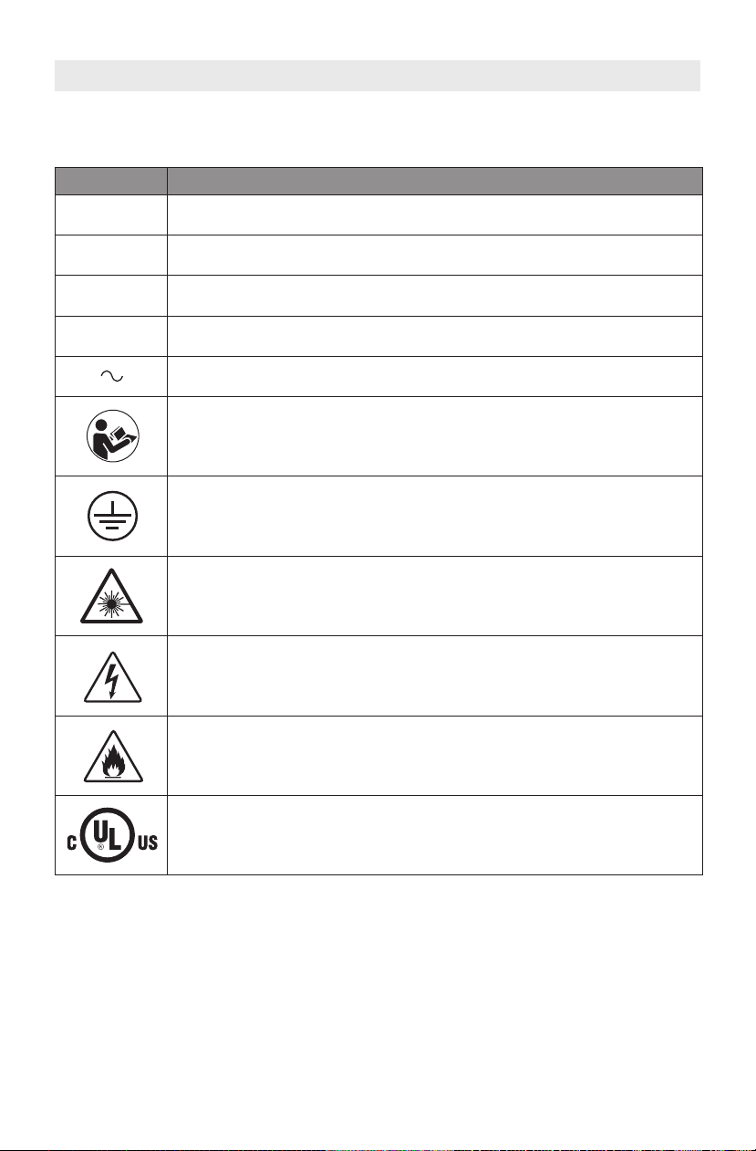
SYMBOLS
IMPORTANT: Some of the following symbols may be used on your LC40. Please study
them and learn their meaning. Proper interpretation of these symbols will allow you to
perate the tool better and safer.
o
Symbol Designation / Explanation
Hz
ø
V
A
Volts (voltage)
Amperes (current)
Hertz (frequency, cycles per second)
Diameter
Alternating current (type or a characteristic of current)
Alerts user to read manual
Earthing terminal (grounding terminal)
Warns of laser radiation. Avoid direct eye exposure. Class 3R laser
product.
Warns of high voltage. Contact with high voltage can cause death or
serious injury.
This fire warning icon calls attention to fire risks that are present while
operating the laser.
This symbol designates that this tool is listed by Underwriters
Laboratories, to United States and Canadian Standards.
6
Page 7

FCC AND IC COMPLIANCE
FCC COMPLIANCE
NOTE: This equipment has been tested and
found to comply with the limits for a Class
B digital device, pursuant to Part 15 of the
FCC Rules. These limits are designed to
pr o v i d e rea s o n a b l e protecti o n agains t
harmful i n t e rf e r e nc e in a r e s id e n t ia l
in stal lati o n. Thi s equip ment ge nera t es,
us e s , and c a n radiat e radio f r e q u e n c y
ener gy and, if not inst alled and used in
ac c o r d ance w i t h th e ins t r u c tions, may
cause h a rm f u l inte r f e r e n c e to r ad i o
co m m u n ication s . How e v e r , th e r e is no
guarantee that interference will not occur in
a particular installation. If this equipment
does cause harmful interference to radio or
televis i o n r e c e pt i o n, w hi c h ca n b e
determined by turning the equipment off
and on, the user is encouraged to try to
correct the interference by one or more of
the following measures:
• R e o r i e n t o r re lo c a te t he r ec e i v in g
antenna.
• Incr e ase the se p arat i on b e twee n th e
equipment and receiver.
• Connect the equipment into an outlet on
INFORMATION ON INTELLECTUAL PROPERTY
a circuit different from that to which the
receiver is connected.
• Con sul t t he deale r o r an e xpe rie nce d
radio/TV technician for help.
Changes and Modifications not expressly
approved by the manufacturer or registrant
of this equipment can void your authority to
op e r a t e this e q u i p m e n t under Federal
Communications Commission’s rules.
INDUSTRY CANADA (IC)
This device complies with Industry Canada’s
licence-exempt RSSs. Operation is subject
to the following two conditions:
(1) This device may not cause interference;
and
(2) T h i s dev i c e must accept any
interference, including interference that
may cause undesired operation of the
device.
The device meets the exemption from the
routine evaluation limits in section 2.5 of
RSS 102 and compliance with RSS-102 RF
exposur e , us er s can ob t a i n Can a d i a n
informa t i o n on RF e xp o s u re and
compliance.
Th e Dr e m el LC 40 is in t ended for las e r
cutting / e n g r a v i ng material s to cr ea t e
objects using digital files and digital designs
that you create or own, or have the right to
use when you operate the Dremel LC40.
When cutting/engraving materials to create
objects using the Dremel LC40, it is your
responsibi lity to e nsure that you do not
infringe any third party intellectual property
right s or v iola te a ny applic abl e laws or
regulat i o n s , s u c h a s U . S . o r f o r ei g n
intellectual property laws.
The Dremel LC40 may not be used to create
objects using digital files or digital designs
protected by intellectual property rights
owned by third parties without such third
parties’ permission to use such digital files
or digital designs for the creation of such
objects. Using the Dremel LC40 to do any of
the following, which are provided to you as
examples and must not be viewe d as an
exhaustive list, may require the permission
of third parties: to create a duplicate or
facsimile (in whole or in part) of any digital
de sign not ow n ed b y yo u, t o cr eate an
object from a digital file you do not own, or
to make an object from a scan of a physical
object that you did not create. It is your
responsibility to obtain such permission. In
some cases, you may not be able to obtain
such permission. Where such permission
cannot be obtained, you must not create
such objects. You must not modify, reverse
engineer, decompile, or disassemble the
Dremel LC40, except as pe r m it t e d by
applicable law.
If you use the Dremel LC40 in any way other
than as rec omm ended and describ ed in
these Operating/Safety Instructions, you do
so at your own risk. Using the Dremel LC40
to m a k e obj e c t s that i nf r i n ge any
intellectual property rights owned by third
pa r ties cou l d result in civ il o r cr i mina l
prosecution and penalties, and you could be
liable f o r m o n ey d am a g e s, f in e s , o r
imprisonment.
7
Page 8

SPECIFICATIONS
LASER SYSTEM
Laser Type: Sealed CO2 Laser Tube
Laser Power: 40W
Laser Classification: IEC 60825-1 Class 3R
Beam Size: 6.5 mm diameter @ 1.2 m
Working Current: 20mA
Wavelength: 10.6 μm
LASER CUTTER WEIGHT & DIMENSIONS
Dimensions: 32” x 20” x 8.25”
(812.5 mm x 508 mm x 209.55 mm)
Weight: 63.3 lbs (28.7 kg) (without Hex
Box™ or accessories)
Shipping Weight: 100 lbs (45 kg)
HEX BOX™ WEIGHT & DIMENSIONS
Dimensions: 7.25” x 11” x 7.25”
(184 mm x 279 mm x 184 mm)
Weight: 10 lbs (4.5 kg)
Total Water Capacity: 35 oz (1 liter)
ELECTRICAL REQUIREMENTS
LC40 input rating: 120V, 60Hz, 6 A
Hex Box™ rating: 12V DC, 4.7 A
SUPPORTED OPERATING SYSTEM AND
SYSTEM SPECIFICATIONS
Compatibility: Mac & PC
•Apple® Mac® OS® X v10.9 or later
(Mavericks)
•Microsoft® Windows® 10
•Microsoft® Windows® 8.1
•Microsoft® Windows® 7 SP1
Browser Compatibility: Chrome, Safari,
Firefox, & IE
Min Screen Resolution: 1024 x 768 Pixels
Ability to Connect Through Network
(Ethernet or Wireless) without Internet
Connection
Wireless connection frequency: 2.4 GHz
OPERATING CAPACITIES
Engraving Area: 18.4” x 12”
(467 mm x 304.8 mm)
Cutting Area: 20” x 12”
(508 mm x 304.8 mm)
Max Engraving Height: 1.25” (32 mm)
Max Cutting Height: ¼” Wood and
Acrylic (6 mm)
OPERATING ENVIRONMENT
Recommended Environmental
Temperature: 60-85F (16-29C)
Sturdy, flat, and level workspace that
holds weight of the Laser, material,
and Hex Box™.
For indoor use only.
8
Page 9

10” (254mm) Min.
8”
(203mm)
Min.
8”
(203mm)
Min.
WALL
30”
(762mm)
Laser Cutter
8”
(203mm)
Min.
8”
(203mm)
Min.
Hex Box™
SPECIFICATIONS
LASER CUTTER & HEX BOX™ CLEARANCE REQUIREMENTS
9
Page 10

MATERIAL USAGE
Table 1
Acrylic
†
LC40 Commonly Used Materials
Aluminum, anodized
Plywood*
†
Cork
Cardboard
Cotton fabric
* Must be California 93120 Phase 2 & TSCA Title VI compliant for formaldehyde
Table 2
ABS
Beryllium oxide
Carbon
Chlorinated plastics
Coated carbon fiber
Coated materials
Epoxy based or phenolic resins
Fiberglass
Fluorine based plastics:
PTFE (Teflon)
Fluorinated ethylene propylene (FEP)
Galvanized metal
HDPE (High Density Poly Ethylene)
Leather, Artificial or Treated
Materials containing:
• Astanine
• Bromine
• Chlorine
• Fluorine
• Formaldehyde (including wood)
• Flame-retardants
• Halogens
• Iodine
Mirrored surfaces
†
Birch Plywood and Acrylic are available from Dremel.
LC40 Prohibited Materials
Denim fabric
Felt (wool)
Glass
Leather, unstained
Maple, solid
Mat board
Nylon
Painted material,
varnished materials
Particleboard, paneling
Polycarbonate
Polychloroprene (CR or
chloroprene rubber, marketed
under the brand name of Neoprene)
Polypropylene foam,
Polypropylene sheet
Polystyrene foam
Polyurethane,
Polyurethane foam
Polyvinyl chloride (PVC) Found in
many common products such as
but not limited to; flooring, siding,
piping, roofing membranes,
credit cards, toys, flexible tubing.
POM Delrin/acetyl.
Rubber
Styrofoam
Wood that has been:
• Coated
• Fumigated
• Pressure treated
• Stained
Oak, solid
Paper
Rubber, laser grade
Walnut, solid
While the LC40 can cut and etch a variety of materials, some materials such as most metals,
cannot be marked and will give less than desirable results. Other materials may not have
acceptable finish quality.
10
Page 11

RESOURCES
Resource Description Location
Quick Start
Guide
Provides an illustrated walkthrough of
how to un-box the laser cutter and start
a job.
Printed version is located in
the box with the laser
cutter. It is also available on
digilab.dremel.com/support/
laser-support
Laser Cutter
LCD
Interface
Dremel LC40
Control
Software
Dremel
Website
DigiLab
Website
Dremel
Customer
Support
Term Definition
Air Assist
Provides step-by-step instructions for
setting up the laser cutter. Also allows
control of the laser head, run recent
jobs, and adjust machine settings.
Provides the interface for setting up,
saving, and sending cutting and
engraving jobs to the laser cutter.
Access project inspiration and
downloads, Dremel product
information, and customer support.
Access information about Dremel
DigiLab products, education projects,
and more.
Contact Dremel for product support,
maintenance, and service.
Air delivery system that helps to control flareups. Air is supplied by the Hex
Box™.
On the laser cutter machine
Enter the IP address of
the laser cutter into the
browser.
dremel.com
digilab.dremel.com
1-844-437-6533
dremel.com/digilab-support
GLOSSARY OF TERMS
Alignment Laser
Auto Array
.bin File
Cut
Design Software
An additional laser diode whose beam results in a red dot that is used to
help align the mirrors.
A software function that creates a grid of the desired size by repeating the
selected image.
A binary file format used to save and load workspace projects to and from a
computer.
Also called "vector", used for cutting through work piece. This function
requires a vector, or line file to execute.
Graphics editing software used to create and manipulate images for laser
cutting and engraving.
11
Page 12

GLOSSARY OF TERMS
Engrave/Etch
Exhaust Hose
Exhaust Shroud
Exhaust Port
Firmware
Greyscale
Hex Box™
Honeycomb Plate
Job A project that is sent to the laser for fabrication.
Laser Head
LC40 Control
Software
Function, also called "raster", used to darken or remove the surface of a
material, rather than cut through it. This function requires an image file to
execute.
Duct that is connected to the laser cutter unit to vent byproducts outside or
into a filtration unit or to outside ventilation.
A metal tubing connection that is screwed onto the rear of the laser cutter
unit over the exhaust vent fan.
An opening on the rear of the laser unit that allows the vent fan to draw air
out of the workspace.
Software that is embedded on the computer hardware of the laser cutter and
controls its operation. Updates to the firmware will be provided by Dremel
and applied to the laser cutter directly over the internet.
Also called "dither", takes a black and white image and assigns different
densities of dots to visually create a number of different shades of grey. Darker
areas of the image will have more dots, while lighter areas will have less dots.
A separate and interconnected part of the laser cutter system that integrates
the water circulation and air assist functions of the laser cutter.
An aluminum tray that rests on the bed and supports the work piece as it is
cut and engraved.
An assembly of components, including a mirror, lens, and cone, which the
laser passes through before making contact with the material.
The laser control software that is provided on the machine and accessed by
a computer through the network connection.
Laser Tube A glass tube located at the rear of the laser unit that generates the laser beam.
Lens
Material The substance of which the work piece or work is composed.
Material Library
Mirrors
Project
Raster Digital art composed of horizontal and vertical rows of pixels.
Score
Spacer Puck
12
A glass lens in the laser head that focuses the beam of the laser for optimal
cutting and engraving.
A listing of materials for which suggested laser settings are predefined in the
Dremel LC40 Control Software.
A set of mirrors that direct the laser beam of the laser from the tube to the
work piece.
A planned piece of work created in the Dremel LC40 Control Software which
can be sent to the laser engraver as a job.
Function used to make a mark on the surface of the material when you want
to emphasize the outline of text or an object
A small cylinder that is placed between the work piece and laser head to
assist in focusing the laser.
Page 13

GLOSSARY OF TERMS
Touch Screen Touch activated full color display.
Vector Art
Vent Fan A fan located in the exhaust port that helps draw air out of the workspace.
Work piece
Workspace
X-Axis Guide Rails
Y-Axis Guide Rails
Art created using vector illustration software programs, such as Adobe
Illustrator
Also called "work" or "material". It is the object to be cut or engraved with the
laser.
a) The area inside of the laser unit that is open for work piece placement
and the movement of the laser head.
b) A screen in the Dremel LC40 Control Software where a job is created. It
provides a graphical representation of the intended job and its position
relative to the general boundaries of the laser working area.
A set of rails at the rear of the laser bed that allow movement of the laser
head to the left or right side of the workspace.
A set of rails on either side of the laser bed that allow movement of the laser
head to the front or rear of the workspace.
®
or Corel Draw®.
INTRODUCTION
Welcome to the world of Dremel Digilab.
Our mission is to mentor you through the
digital fabrication process and share best
practices for bringing your ideas to life.
Lase r c ut ti ng and e n gr a vi ng are
proc e s s e s that wi l l invok e
expe r i m e nt at io n a n d pe r s i s te nc e.
Thankfully, the Dremel experts are here
to make your job easier with online tips,
documentatio n, and live support. T he
Drem e l L a s e r C u t te r b r i ng s ro b u st
func t i o n al it y such as n e t w or k
connectivity, recommended settings for
co mmon ly used materi als, and mul tisensor checks. To get started with the
La s e r Cutter fol l o w the in i tial se t u p
routine on the touch screen to guide you
through the hardware and software setup
of the machine.
You can register your Laser Cutter and
crea t e a user profi l e by goi n g to
dremel.com/support/product-registration.
Your profile gives you access to a variety
of laser projects and support. Once setup
and regi stratio n is complete , you are
ready to start making.
TOOLS & SUPPLIES NEEDED FOR SETUP
Distilled Water Funnel Scissors Screwdriver
13
Page 14

UNPACKING
Box 2
Tote Bag
& Box 1
LC40
1 2
3 4
Box 3
Straps
Two pers o n l i f t
laser cutter alone may result in personal
requ i r e d .
injury.
Lifting the
Crea te a wor kst ation. Prep are a fl at,
sturd y tab l e or work b e n c h t h a t c a n
support the weight of the Laser and Hex
Box™. The workstation should be close to
an e le c tr ic a l ou t l e t an d allo w for
necessary ventilation described in the
SETUP sectio n "Exhaust Connec tions"
page xx.
Open the top of the box.
1. R e mo ve Re u s a bl e T o t e B a g f r o m
packaging and pull out box 1. Open lid
to reveal the project sample material
and the Honeycomb Plate.
2. Remove Instructional Manual, Water
Hoses, Air Tube, Screws, Hex Box™
Cap, Hex Key W rench, S pacer Puck
from box 2.
3. R e mo ve f oa m t o rev e a l t he La s e r
Cutter. Use two people to lift Laser
Cutter out of box by straps and place
on workstation. After the Laser Cutter
has been taken out of the box, hook
straps to the Reusable Tote Bag. DO
NOT CUT STRAPS.
4. Open the lid of the Laser Cutter to
reveal box 3 with Hex Box™, Exhaust
Duct, and Exhaust Shroud.
Note: Sav e the D remel Digi Lab Las er
Cutter packaging for future transport and
storage.
14
Page 15

KIT CONTENTS
DIGILAB
LC40 Laser Cutter
For English Version
See page 2
Version française
Voir page 37
Versión en español
Ver la página 73
IMPORTANT
Read Before Using
IMPORTANT
Lire avant usage
IMPORTANTE
Leer antes de usar
1-844-4DRML3D (1-844-437-6533) www.dremel.com
P.O. Box 081126 Racine, WI 53408-1126
Operating/Safety Instructions
Consignes d’utilisation/de sécurité
Instrucciones de funcionamiento y seguridad
Call Toll Free for Consumer Information & Service Locations
Pour obtenir des informations et les adresses de nos centres de service après-vente, appelez ce numéro gratuit
Llame gratis para obtener información para el consumidor y ubicaciones de servicio
A
l
c
o
h
o
l
P
r
e
p
P
a
d
A
l
c
o
h
o
l
P
r
e
p
P
a
d
The LC40 laser cutter is shipped with the following included parts and accessories:
Reusable Tote Bag Project Sample
Material
Operating/Safety
Instructions
Ethernet
Cable
(2) Hose Clamps Hex Box™
Connector Cord
Honeycomb Plate Quick Start Guide
Water Hose
(1 blue & 1 clear)
Hex Box™
Air Tube
(black)
Hex Keys
Water Tank Cap
Lens Cleaning Wipes Spacer Puck Alignment Paper Laser Cutter
Hex Box™ Exhaust Hose Exhaust Shroud
15
Page 16
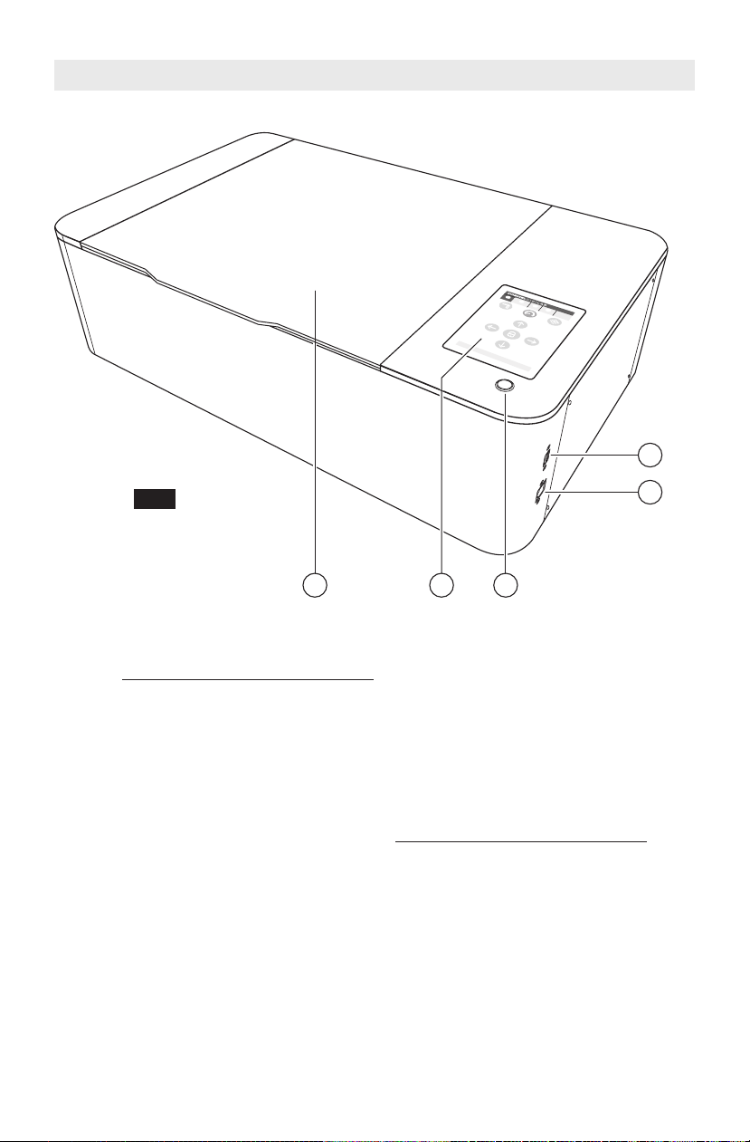
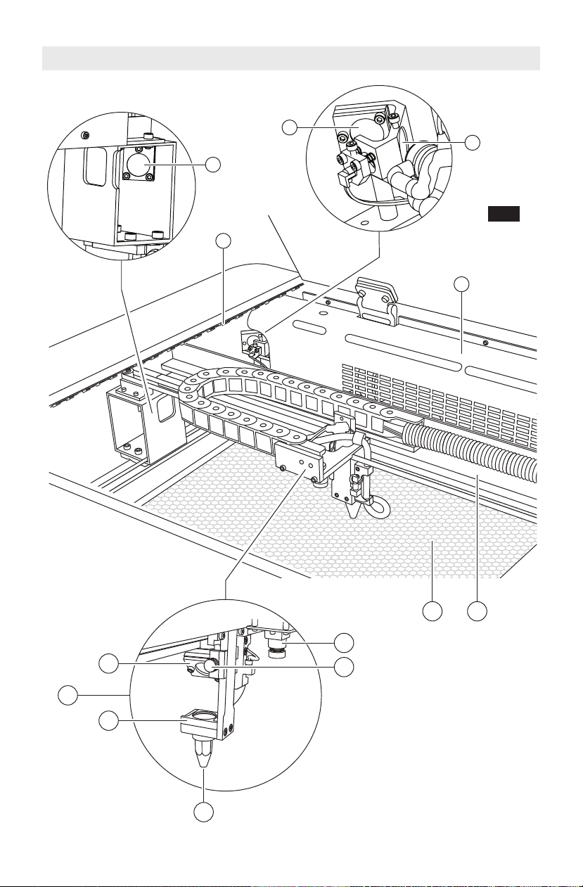
GETTING TO KNOW YOUR LASER CUTTER
21 3
5
4
Fig. 1
LC40 Laser Cutter
1. Lid
2. Touchscreen
3. Start Button
4. USB Port (for service only)
5. Ethernet Port
6. LED Lights
7. Laser Tube Shroud
8. Honeycomb Plate
9. Gantry
10. Mirror 1
11. Beam Combiner Lens
12. Mirror 2
13. Laser Head
a. Mirror 3
b. Focus Lens
c. Air Nozzle
d. Laserhead Knob
e. Wide Angle Camera
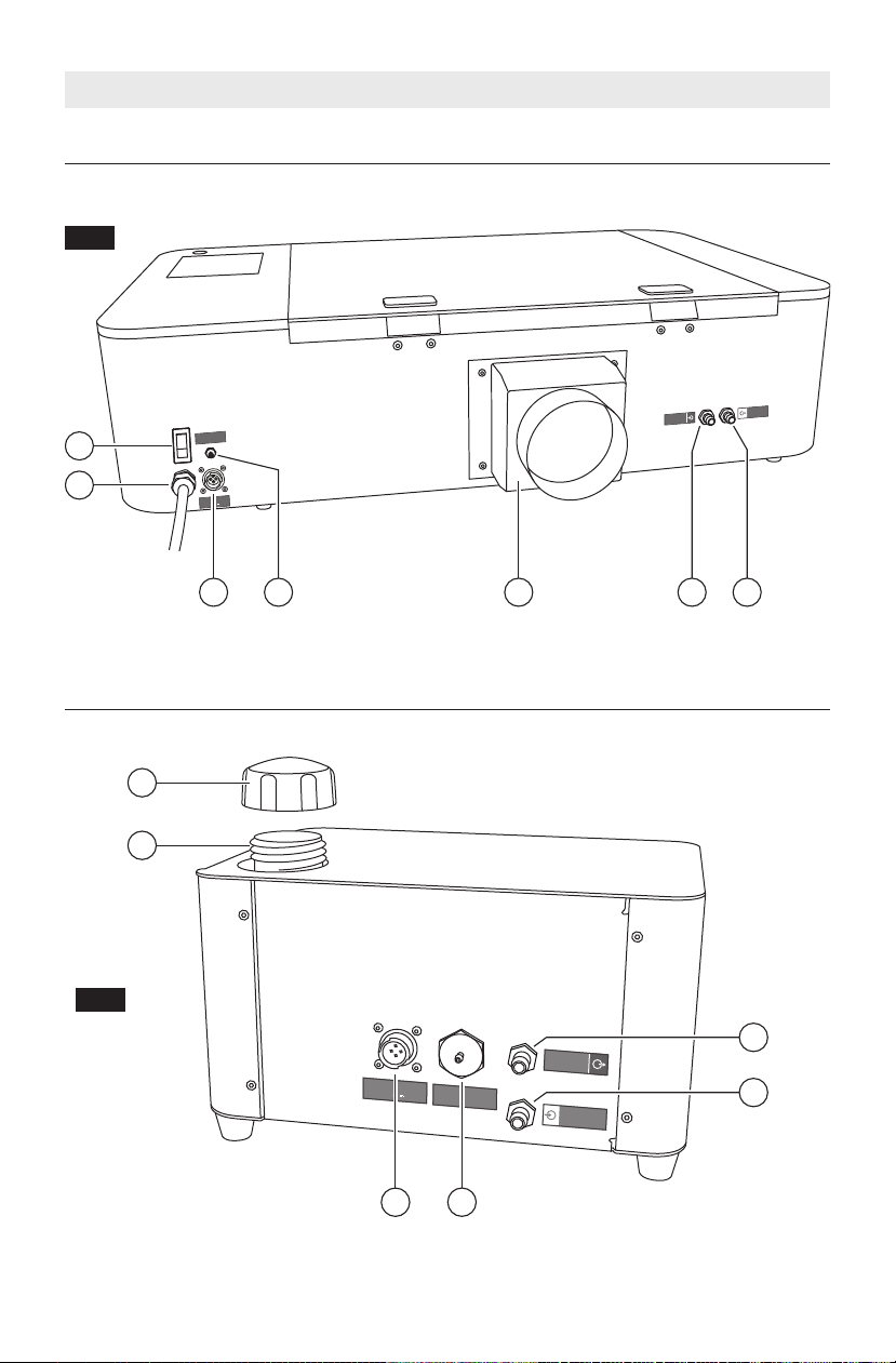
16
14. Power Switch
15. Power Cord
16. Hex Box™ Power Outlet
17. Air Inlet
18. Exhaust Shroud
19. Water Outlet
20. Water Inlet
Hex Box™
21. Water Tank Cap
22. Water Tank
23. Power Inlet
24. Air Outlet
25. Water Outlet
26. Water Inlet
Page 17
GETTING TO KNOW YOUR LASER CUTTER
c
e
d
b
a
2
.
0
”
1
2
6
7
8 9
11
1
0
13
Fig. 2
17
Page 18
A
I
R
T
U
B
E
T
U
Y
A
U
À
A
I
R
T
U
B
O
D
E
A
I
R
E
W
A
T
E
R
O
U
T
S
O
R
T
I
E
D
’
E
A
U
S
A
L
I
D
A
D
E
A
G
U
A
W
A
T
E
R
I
N
E
N
T
R
É
E
D
’E
A
U
E
N
T
R
A
D
A
D
E
A
G
U
A
H
e
x
B
o
x
1
2
V
23
24
25
22
21
26
A
I
R
T
U
B
E
T
U
Y
A
U
À
A
I
R
T
U
B
O
D
E
A
I
R
E
H
e
x
B
o
x
1
2
V
18 19 2017
14
16
15
W
A
T
E
R
O
U
T
S
O
R
T
I
E
D
’
E
A
U
S
A
L
I
D
A
D
E
A
G
U
A
W
A
T
E
R
I
N
E
N
T
R
É
E
D
’
E
A
U
E
N
T
R
A
D
A
D
E
A
G
U
A
Fig. 3
GETTING TO KNOW YOUR LASER CUTTER
REAR VIEW OF LASER CUTTER
REAR VIEW OF HEX BOX™
18
Fig. 4
Page 19
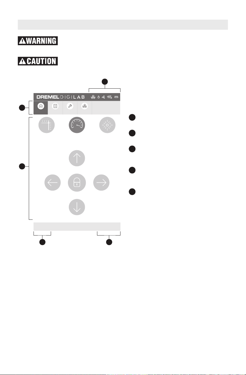
LCD TOUCH SCREEN
1
2
3
45
192.168.1.115 v1.0.0
LASER
HOME
JOG SPEED
FAST
TEST FIRE
H
OME JOB HISTORY TOOLS NETWORK
1
2
3
4
5
Observe all provided warnings and safety instructions when using
the Dremel LC40. Failure to do so may result in fire, equipment
damage, property damage or personal injury.
Do not tap or scratch LCD screen with sharp objects. The LCD
screen may become damaged.
The LC40 touch screen allows control of
the basic functions of the laser without
the need to connect to a computer.
St a t u s Ba r — D i s p l a ys in f o rmation
about selected conditions of the LC40.
Menu Bar — D ispla ys the icon s a nd
names of the Touch Screen menus.
Co ntr o l I n ter face — Inform atio n or
additional action pertaining to selected
menu item.
IP Address — A unique number used to
connect t h e L a s er C u tt e r over a
network to a web browser.
Firmwar e Ve r s i o n — Di sp l a ys th e
currently installed firmware version.
19
Page 20
2
HOME JOB HISTORY TOOLS NETWORK
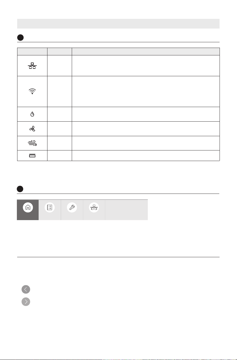
LCD TOUCH SCREEN
1
Status Bar
Status Icon Name What it means
Ethernet
Wireless
Water
Cooling
Vent
Fan
Air
Assist
Lid WHITE: Lid is closed. RED: Lid is open.
Note: Water Cooling. Vent Fan and Air Assist icons will only update in real time. (When the Hex Box
is activated by the LC40).
Menu Bar
LC40 is connected to a computer or a network router via
Ethernet Port.
The icon will disappear when there is no Ethernet connection.
LC40 is connected to a computer or network router via wireless.
The icon will disappear either when there is no wireless
connection or when the Ethernet icon is active. When LC40 is
connected with both Ethernet and Wireless, only the Ethernet
icon will display.
WHITE: Cooling system functioning normally.
RED: Cooling system needs attention.
WHITE: Vent fan functioning normally.
RED: Vent fan needs attention.
WHITE: Air assist functioning normally.
RED: Air assist needs attention.
HO M E — Acc e ss to la ser h e a d po sitio n
controls and to test fire the laser.
JOB HISTORY — Lists previously run jobs
and provides option to re-run them.
When necessary, the LCD touch screens will offer options to return to the previous screen
or advance to the next screen.
Tap to return to previous screen.
Tap to proceed to the next screen.
20
TOOLS — Information about the unit and
settings.
NETWO RK — Inf orma tio n and acces s to
network connection settings.
Page 21
HOME > UNLOCKED
192.168.1.115 v1.0.0
LASER
HOME
JOG SPEED
FAST
TEST FIRE
HOME JOB HISTORY TOOLS NETWORK
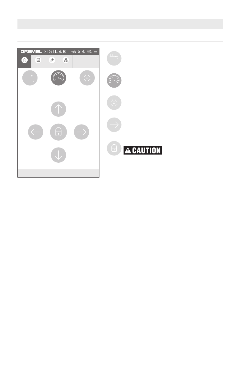
LCD TOUCH SCREEN
LASER HOME – Moves the laser head
back to its origin location. Button will
flash when homing is necessary.
JOG SPEED – Toggles between fast and
slow laser head movement speed. Fast is
default speed.
TEST FIRE – Enable the laser to fire for a
sh o r t period to identi f y its lo c a t i o n
relative to the material.
Directional Arrows
Moves the la ser hea d in di rect ion of
arrow.
Laser Head Locked (default)
Do not move the laser
head b y hand w h e n
locked. Moving a locked laser head by
hand may result in damage to the gantry
system.
A cl osed lock icon indicat es that the
lase r head is loc ked and c an only be
move d us in g th e di re ct io n al ar r o w
buttons.
Pres s i n g the l o ck butt o n toggl e s
between locked or unlocked laser head
setting.
21
Page 22
192.168.1.115 v1.0.0
L
ASER
H
OME
J
OG SPEED
F
AST
T
EST FIRE
HOME JOB HISTORY TOOLS NETWORK
HOME > LOCKED
LCD TOUCH SCREEN
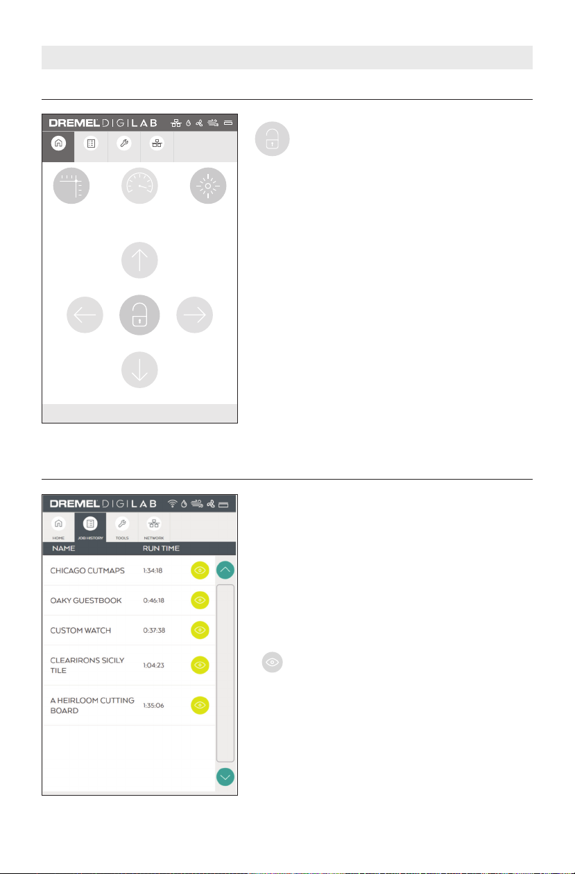
Laser Head Unlocked
An open lock icon indicates th at the
laser head can be moved by hand.
Note: When Laser Head is unlocked the
Dire cti onal Arrows and Speed v irtual
buttons are nonfunctional.
JOB HISTORY
22
This tab displays jobs received by the laser cutter.
As received from the factory, this list is empty. The
Factory Reset opt io n will clear J ob His to ry . Job
creation is explained in the Software Section.
Once a job is sent from the software to the laser, it
will appear in the job history tab.
NAME — the name of project job(s) within the Job
History list.
RUN TIME — required time to complete project.
Tap to preview the job and open the submenu for the job.
Page 23
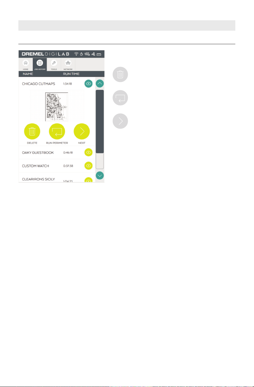
JOB HISTORY
LCD TOUCH SCREEN
This screen displays options for the Job selected
from the list.
DELETE – Delete files from the Job History
list.
RUN PERIMET E R – Exec u t e s t h e r u n
perimeter.
NEXT – Changes the text to LOADING. The
Job will prepare to start.
Note: If a job is rerun, the system safety checklist
will appear (see page XX Operation Screens).
23
Page 24
TOOLS > MENU SCREEN
LCD TOUCH SCREEN
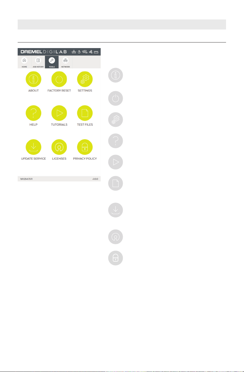
This screen displays available tools for mangement
of the laser cutter.
ABOUT — Displays laser cutter information
su c h as m o d e l nu m b e r , se r i a l nu m b e r ,
firmwar e versio n , usag e , and ne tw o r k
information.
FACTORY RESET – Remove all information
stored o n L C40 and r etu rn it to fact ory
defaults.
SETTINGS – Shows language and display
settings.
HELP - Displays service menu with customer
service contact information.
TUTORIALS – Displays short tutorials on
operation of the laser.
TEST FILES – Displays and allows execution
of test files to verify proper operation of the
laser.
UP D A T E SER V I C E – D i s p l ays av a i lable
service updates from Dremel. Updates are
pushed to t h e unit a n d cann o t be
re q u e s t e d . The u s e r has t h e option to
accept or ignore the update.
LI CEN S ES – Displ ays the lists of OP EN
SOURCE software licenses associated with
the unit.
PR I V ACY P O LICY – Di s plays a w e bsite
address for further detail s on Dremel
privacy policy.
24
Page 25
LCD TOUCH SCREEN
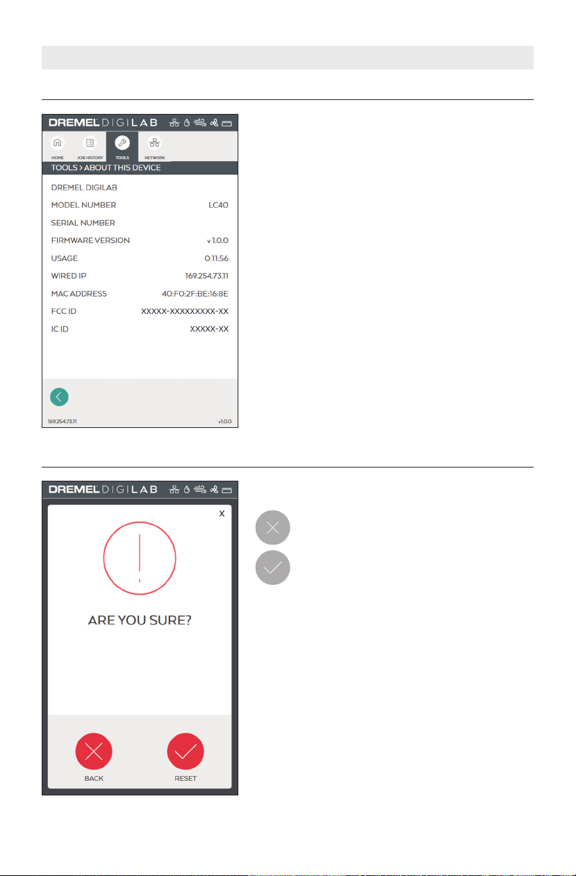
TOOLS > ABOUT THIS DEVICE
TOOLS > FACTORY RESET
This sc ree n disp lay s l aser cutt er hardw are and
software information.
MODEL NUMBER — Displays unit model number.
SERIAL NUMBER — Displays unit serial number.
FIRMWAR E NUMBE R — Dis p l a y s th e curre n t l y
installed firmware version.
USAGE — Displays total hours of time that jobs have
been run.
WIRED IP — Displa y s Et h e rn e t IP ad d r e s s , if
connected.
WIRELESS I P — D is plays IP address assigned b y
wireless router.
MAC ADDRESS — Displays unique identifier assigned
to a network interface controller.
FCC ID — Displays FCC ID
IC ID — Displays IC ID
This screen allows for verification of factory reset
selection.
BACK – Tap to can cel factory rese t a nd
return to Tools > Menu Screen.
RESET – Tap to perform factory reset.
NO TE - T he fol lo win g act ions o ccu r when F act or y Re se t i s
performed:
• EULA screen will appe ar on next power up and needs to be
accepted.
• Country and Language selection will appear on next power cycle.
• Job history on the LCD software Interface will be cleared.
• Default material settings will be restored for the Laser browser
interface software.
• User custom material settings will be cleared.
• Network configuration will be restored to default with all custom
settings cleared.
• Saved wireless network and password will be cleared.
• Ve ntilati on setting will re vert back to default of EX TERNAL
FILTRATION/VENTILATION SYSTEM.
25
Page 26
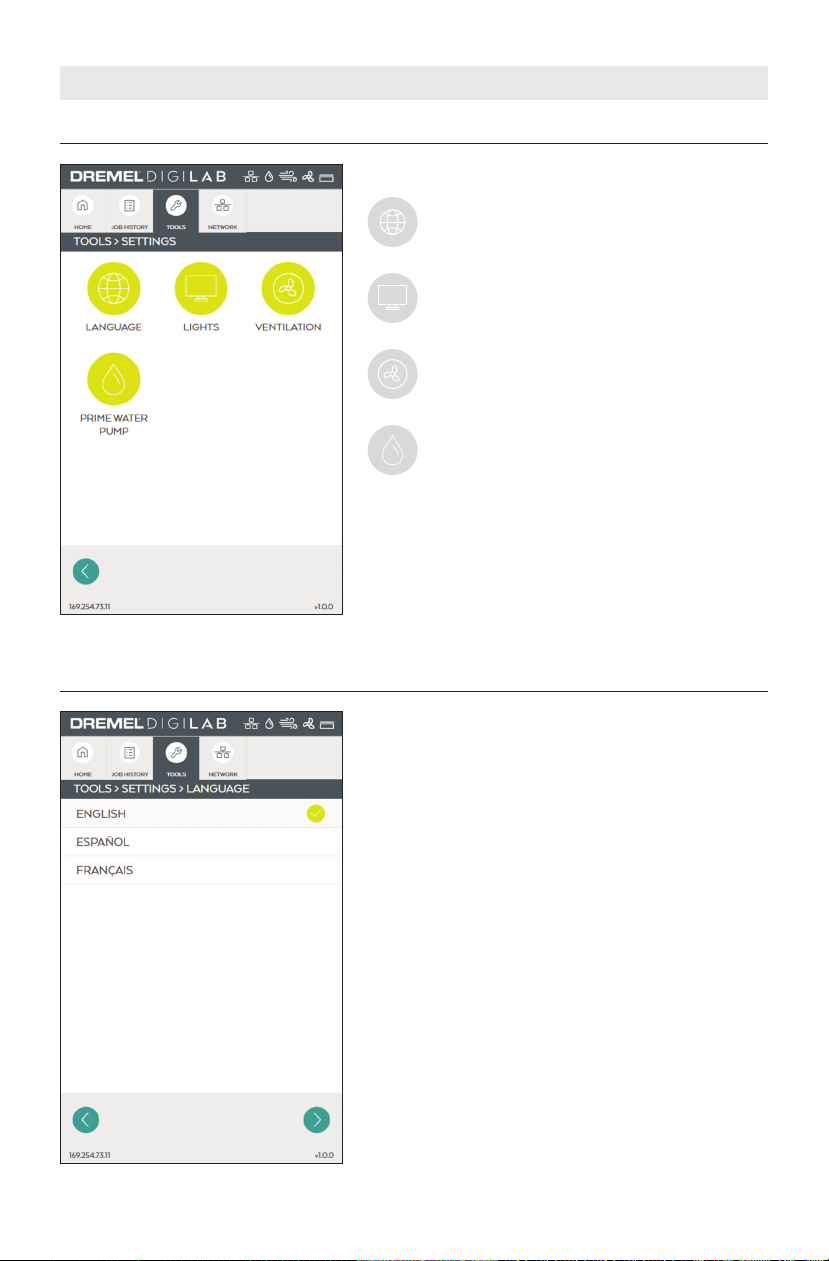
TOOLS > SETTINGS
LCD TOUCH SCREEN
This screen displays available settings
LANGUAGE – Displays a sub-menu where
LCD me n u w a r n in g s la nu a g e c a n b e
selected.
LIGHTS – Disp l a y s a sub-me n u whe r e
cabinet LED lights can be turned “ON” and
“OFF”.
VENTILATION – Displays a sub-menu screen
where ventilation type can be selected.
PRIM E WATER P UMP – Disp lay s a submenu with water pump controls.
TOOLS > SETTINGS > LANGUAGE
This screen displays and allows selection of different
languages.
Note: Choosing the language on this screen does not
set the software language on the computer, only the
LCD warning screens are affected.
26
Page 27
LCD TOUCH SCREEN
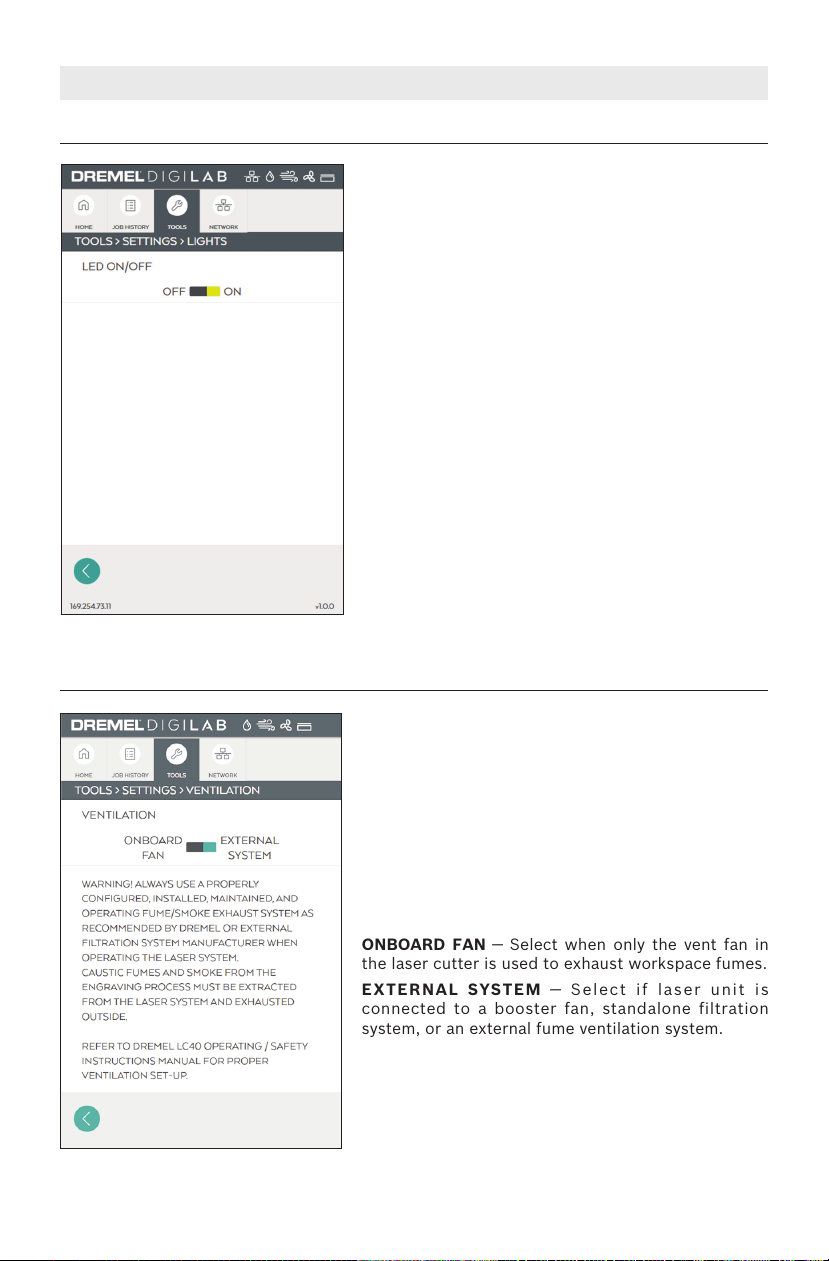
TOOLS > SETTINGS > LIGHTS
This screen displays the option to turn ON or OFF
the LED lights that illuminate the workspace.
LED ON/OFF — Turns “ON” and “OFF” LED lights.
LED lights are “ON” by default. If the main power
switch is cycled, the light setting will return to the
default.
TOOLS > SETTINGS > VENTILATION
This screen provides an option to select between
the internal vent fan and external ventilation systems
such as a booster fan, a standalone filtration system,
or an external fume ventilation system.
To assure proper removal of fumes produced during
operati o n o f Dremel L C 4 0 laser c u t t e r , th e
ventilation selection must match the actual fume
extrac tion set up. Dremel LC40 must be set up
according to instructions provided in the Exhaust
Connections chapter of the Setup section on page
XYZ to assure proper ventilation.
ONBOARD FAN — Select when only the vent fan in
the laser cutter is used to exhaust workspace fumes.
EXTERNA L SY ST E M — Se l e c t if la s e r uni t is
connected to a booster fan, standalone filtration
system, or an external fume ventilation system.
27
Page 28

LCD TOUCH SCREEN
TOOLS > SETTINGS > PRIME WATER PUMP
This screen provides control to start the water pump
during priming of the laser cooling system.
START – Starts the coolant pump.
This screen provides control to stop the water pump
during priming of the laser cooling system.
STOP – Stops the pump.
28
Page 29

TOOLS > HELP
LCD TOUCH SCREEN
Th i s screen dis p lays cus t omer ser vice con tact
information.
TOOLS > TUTORIALS
This screen provides access to available tutorial.
FO CUS LA SER HEAD – Instr ucti ons fo r
adjusting the laser head to focus the laser
beam on the work piece surface.
MACHI NE SETUP – In str ucti ons for t he
initial setup of Dremel LC40.
OTHER – Instructions for cleaning of the
mirrors and lens.
29
Page 30

TOOLS > TUTORIALS
LCD TOUCH SCREEN
Sequence of screens stepping through JOB PREP.
Sequence of screens stepping through HOOK UP.
30
Page 31

TOOLS > TEST FILES
LCD TOUCH SCREEN
This screen displays available test files and allows
their execution.
Tes t files are used to verify proper operation of
select functions and features of Dremel LC40 laser
cutter.
• Test Files "CUT TEST - BOX 1" thru "CUT TEST BOX 12" are used to identify optimized cut and
score settings.
• Test Files "ENGRAVE TEST" are used to identify
optimized engrave settings.
• Recommended material size for tests: 12”x20
Preview the test file.
This sample screen illustrates how the option to run
a test file can be selected.
NEXT — To start running the job.
31
Page 32

LCD TOUCH SCREEN
TOOLS > UPDATE SERVICE
Th is scr een pr ovid es n etwo rk c onne ctiv ity and
status of update service from Dremel.
LOCAL NETWORK – Shows whether ethernet or
wireless is connected to the local network.
UPDATE SERVICE – Indicates if the unit is able to
comm uni cat e with the up dat e s erv ice (Internet
connection is required).
UPDATE STATUS – Provides information regarding
any new software updates.
LAST CONNECTION TIME – Shows how long ago
the last update service connection was made. If unit
is actively connected to update service, then the
LAST CONNECTION TIME will not be shown.
If an u pdate is available, an UPDATE AVAILABLE
screen and UPDATE PENDING screen will be shown.
The update prompt, which appears on the Home
menu screen, allows allows a user the option of
accepting the update or deferring for another time.
TOOLS > LICENSES
32
Displays information regarding open source software
licenses.
Page 33

LCD TOUCH SCREEN
000.000.000
TOOLS > PRIVACY POLICY
Provides the web address where the current and
complete privacy policy can be reviewed.
NETWORK > MENU SCREEN
This screen displays the Network connection menu.
Available options allow connection or disconnection
from the wireless network and set up a static IP
address.
WIRELESS – Setup or modify a wireless
local a r ea network co n n ec t i o n for t he
Dremel laser cutter to connect to.
STATIC IP – Setup the Dremel laser cutter
to use a Static IP address or default to a
DHCP (Dynamic Host Configuration Protocol
address) IP address.
33
Page 34

NETWORK > WIRELESS
TOUCH SCREEN
This screens displays wireless networks detected by
Dremel LC40.
Selecti n g an availa b l e netw o r k will sta r t the
connection process.
Wireless network signal strength indicator.
This scre en display s t he pass word p rompt that
ap p e a r s when a p a s s w o r d pr o t e c t e d wi r e l e s s
network is selected.
34
Page 35

NETWORK > WIRELESS
UNA BLE TO CONNECT
ACCEPT
RETRY
TOUCH SCREEN
This scree n dis plays a not ification that a ppears
when a successful wireless network connection is
made.
DONE – Return to Network menu screen.
This scree n dis plays a not ification that a ppears
when co n n e c t i o n to the wi r e l e s s ne tw o r k is
unsuccessful.
RETRY – Allows adjustment of the network
information and an attempt to connecting
again.
ACCEPT – Return to Network screen.
35
Page 36

NETWORK > STATIC IP
TOUCH SCREEN
This screen displays network set up options.
WIRELES S IP – A l l o w s s e t u p a n d
con f i g u r a t i o n of t h e Wireless Network
Connection.
WIRED IP – Allows setup and configuration
of the Wired Ethernet Network Connection.
This screen displays options for setting a static IP
address for a wireless or a wired (LAN) network.
STATIC IP – Allows selection of Static IP adress.
DHCP – A l l ow s select i o n of Dynam i c H os t
Configuration Protocol address IP address. Values
displayed on IP Address, Netmask, and Gateway are
ignored but saved for future use.
AUTO DNS – Allows the Dremel Laser Cutter to use
the domain name system server as determined by
the network router.
MANUAL – Allo ws for i nputting a specific DNS
server IP address.
Edit settings
SAVE – Save Static IP settings.
CANCEL – Cancel Static IP setup.
36
Page 37

TOUCH SCREEN
OPERATION SCREENS
These screens appear during operation.
CHECKLIST SCREEN
Th is s cree n di spla ys s y stem ch ecks pe r form ed
automatically by Dremel LC40 and operator inputs
that must be completed before a job can be started.
CHECKLIST SCREEN — ERRORS DETECTED
Displays errors detected in systems of the Dremel
LC40 while it is preparing to start a job. The status
bar will also display red icons for system or systems
where errors were found.
Link to a trouble shooting tutorial related to
the system where an error was found.
37
Page 38

OPERATION SCREENS
TOUCH SCREEN
If all icons at the top are white, then items in the
checklist should be green.
Manual checks that can be completed after
the work piece is placed in the workspace
and laser head adjusted using the spacer
puck.
To start the job the lid must be closed and the Start
Button rapidly pressed twice.
JOB IN PROGRESS
This scre e n di s p l a y s th e jo b fi l e na m e , ti m e
remaining to complet e the job, and two control
buttons.
PAUSE - Temporarily pause the job, which
can be resumed from the same place.
STOP – Cancel the current job.
38
Page 39

0
1
2
3
4
5
6
7
8
9
1
0
1
1
0
1
2
3
4
5
6
7
8
9
1
0
11
0 181716151413121110 9 8 7 6 5 4 3 2 1 19
0 181716151413121110 9 8 7 6 5 4 3 2 1 19
IMPORT REDOUNDO A UTO ARRAY MATERIAL OPTIONSTIME: 00:00:00 RUN PERIMETER
S
TART
F
ILE EDIT HELP PROJECT NAME: JOB 1
LASER CUTTER
Workspace Saved
1
2
5
6
7
4
3
8
DREMEL LC40 CONTROL SOFTWARE
1
2
3
4
5
6
7
8
This section introduces the major interface features of the Laser Control Software. The Laser
Control Software is a combination of print driver and control software that communicates
with, downloads jobs to, and controls the laser system. There is no download required. The
software will link a web browser with the LC40 using the IP address (found at the bottom of
the LCD home screen) on the local connection (Wireless or Ethernet).
Menu Bar — includes the following
menu options: File, Edit (shown when
a project is opened), and Help.
Tool Bar — inc lude s the followin g
tool s : Impo r t , U n d o, R e do , A u to
Array, Material, Time, Options, Run
Perimeter, and Start.
Workspace — On-screen area where a
job is created. Provides a graphical
representation of the intended job
and it s p o s i ti on re l a ti ve to t h e
gene r a l bou n d a ri e s of th e l a s e r
working area.
Project Name — displays the name of
the current project.
Zoom In — enlarges workspace screen
detail.
Zoom Out — reduc e s wo r k sp ac e
screen detail.
Return to Default Size — auto size to
fit window.
Stat u s — di s p l ay s st a t us o f t h e
current project.
39
Page 40

DREMEL LC40 CONTROL SOFTWARE
FILE EDIT HELP PROJECT NAME: JOB 1
LASER CUTTER
A B C
Menu Bar
A. FILE
OPEN — select to open a file.
IMPORT — import a file or use the camera capture feature to create a file or place a picture
of your laser bed in the background of your workspace.
B. EDIT
REDO — to redo most recent action/change.
UNDO — to undo most recent action/change
COPY — select to copy the object that is highlighted.
DUPLICATE — select to duplicate the object that is highlighted.
PASTE —
FLIP HORIZONTAL — select to flip horizontal the object that is highlighted.
FLIP VERTICAL — select to flip vertical the object that is highlighted.
ROTATE RIGHT — select to rotate right the object that is highlighted.
ROTATE LEFT — select to rotate left the object that is highlighted.
SELECT ALL — select to select all.
DESELECT ALL — select to deselect all.
select to paste the object that is highlighted.
C. HELP
ABOUT YOUR LASER — select to see more details about your laser cutter.
MANUAL — select to access the laser manual.
TUTORIALS — select to see tutorials for your laser.
FAQS — select to see a list of frequently asked questions with answers.
PROJECT INSPIRATION — select to browse project inspiration.
CUSTOMER SERVICE — select to see customer service contact info.
40
Page 41

Tool Bar
I
MPORT
R
EDO
U
NDO
A
UTO AR RAYMATE RIA L
O
PTIONSTIME: 00:00:00
R
UN PERIMETER
START
A B C D E F G H I
A
B
C
D
DREMEL LC40 CONTROL SOFTWARE
IMPORT
Click to impor t a fil e or use the camera
capture feature to create a file or place a
picture of the laser bed in the background
of the workspace. Alternatively, the file can
be dragged and dropped directly into the
workspace.
FILE – Use import/file to bring in a file as
typically done in other software programs.
For PDF files the options are to bring in only
cut files, only engrave files, or both. Select
the option from the drop down menu. All
other file types will default to either engrave
or cut based on their optimal application.
UNDO
Click to undo most recent action/change.
REDO
Click to redo most recent action/change.
AUTO ARRAY
Choose the object to duplicate. Then click
and high l i g h t th e nu m b e r of ti m e s to
duplicate the object.
CAPT URE – Use impo rt/ captu re to take
advantage of the camera capture feature.
This can be used to either place a picture of
the material that’s on the honeycomb plate,
into the bac k g r o u n d o f t h e so f t w a re
worksp ace Thi s f eatur e can be use d f or
placing a file on top of an oddly shaped
material, or to take a picture of a sketch,
and transform that sketch into a file that
can be engraved or cut.
41
Page 42

DREMEL LC40 CONTROL SOFTWARE
E
F
G
MATERIALS
Observe a l l p r o v i d e d
warning s and safe t y
instructions when using the Dremel LC40.
Failure t o d o s o m a y r e s u l t i n f i r e,
equipmen t dam age, property damage or
personal injury.
Never engrave or cut any
unknown material. Only
engrave material s recommended by the
manufacturer. The vaporization/melting of
many materials, including but not limited
to PVC and polycarbonates, can give off
hazardous fumes. Always refer to the Safety
Data S h e e t (SD S ) from t h e mat e r i a l
manufacturer to determine the response of
any w o r k m a t er i a l t o e x tr e m e h ea t
(burning/fire hazard) to prevent hazards.
Click to select a material from the list of
Dremel provided defaults, or choose “more”
to a dd / d e le t e /e d i t t h e list of f av o r i te
materials. Use the star to denote a default
material that will be saved and used for all
jobs, until changed. The settings that are
populated when a material is selected will
be applied to all files brought in, unless
edited in the print settings box, or changed
in the materials list.
TIME
Click to calculate a rough estimate of how
long the job will take to complete.
OPTIONS
Display s mo r e ad v a nc e d settings an d
defaults.
42
Page 43

DREMEL LC40 CONTROL SOFTWARE
H
I
RUN PERIMETER
Laser head will mov e along the exte rior
perimeter of the job. Click again to stop this
motion, otherwise it will continue running.
PAUSE – Appears once a job starts and will
pause the job.
START
This button will send the job to the laser.
STOP – Appears once the job starts and will
cancel the job.
PRINT SETTINGS
A print s e t t i n g s bo x will pop u p when
clicking on an imported file. There are two
ta b opt i o n s at th e top (Cu t / S core a n d
Engrave ) , an d only th e on es that ar e
applica b l e f o r t h a t f i l e t y p e w i l l b e
highlig h t e d . T h i s b o x c a n b e m o v ed
anywhere on the screen simply by dragging
it . The jog i n the t o p right c o r n e r wil l
expand “ad v a n c e d ” se t t in g s fo r mo r e
control. The “X” will minimize the box and
can be reopened by clicking on the pencil
that appears.
CUT
This function is used when cutting through
a work piece. This function is also called
“vector” since a vector, or line file is needed
in o rder to exe cute. The laser h ead will
follow the lines of the file. The software will
detect up to 21 different colors in a line file
and allow adjustment of the print settings
based on those colors. The order that the
different colors are cut can be adjusted in
the p rint previ ew s cre en o nce re ady to
send.
HEAT – A djus t how quick ly t he l ase r is
firing, or how much heat is generated on the
surface of the work piece. Turning up the
heat will cause charring for materials like
wood or paper, but will create a glossy edge
for a material like acrylic.
SPEED – Adjust how quickly the laser head
moves. Slowing the laser head down allows
it to cut deeper into the work piece, while
turning the speed up prevents the cut from
going as deep.
DEPTH – adjust to control how deep the
laser will go into the work piece. Turning up
the depth will increase the likelihood that
th e wor k pie c e will be c u t all the w a y
through.
# OF PASSES – adjust to control how many
times the lase r trac e s ove r the lines .
Increasing the number of passes means the
laser will execute that job, then immediately
execute it in the exact same loca t i o n
however many times entered. Increasing the
number of passes can be an effective way to
ensure the work piece is cut all the way
through, especially as the thickness of the
material goes up.
SCORE
A function when it is preferred not to cut all
the wa y t h r o u g h the wo rk piec e . This
function requires a vector, or line type file
and is most useful when emphasizing the
outline of text or an object. It is very similar
to “cut,” but the software will default to
less pow erful settings , in an atte mpt t o
mark the work piece, but not cut all the way
through it.
Print Settings box (Cut)
Print Settings box (Score)
43
Page 44

DREMEL LC40 CONTROL SOFTWARE
ENGRAVE
This fu nc t i on dark e n s or re m o ve s th e
su r f ace o f the wor k pi e c e , ra t her t h a n
cutting th rou gh it. T his funct ion is also
known as “raster” and will require an image
file to execute. The laser head will move
side to side like an inkjet printer.
Print Settings box (Engrave)
BLACK/WHITE THRESHOLD – Use this to
adjust the amount of black that is included
in the image. The furthest left setting will
include a larger amount of black from the
file, whil e the furthe st righ t s etting will
include less black, or a larger amount of
white.
GREYS CALE – Ta kes a black an d whit e
image and assign s differen t densi ties of
dots to visually create a number of different
shades of grey. Darker areas of the image
will have more dots, while lighter areas will
have less dots. This is useful for images that
ha ve a lot of di f fere n t colors , an d it is
desired that the finished product appear
more realistic. This setting can be toggled
on or off.
INVERT – This setting will transform the
im a g e so tha t the whi t e ar e a s be c ome
black, and the black areas become white.
DEPTH – Adjust to control how deep the
laser will go into the work piece. Turning up
the depth will remove more material, so
that a noticeable void is felt when touching
the work piece, creating almost a 3D effect.
Turning d o w n the d e p t h will k e e p the
surface of the work piece relatively flat or
even.
SPEED – Adjust how quickly the laser head
moves. Slowing the laser head down will
ge ner ally ma ke the engr a vin g darke r o r
deeper, while turning the speed up typically
results in a lighter finish.
RESOLUT I O N – 3 differe n t resolu t i o n
options are available: low, medium, high.
This setting adjusts the DPI (dots per inch)
in the image, the low setting will be faster
and lig ht er tha n the high set ti ng . In l ow
setting th e resolu t i o n is p ix e l a t ed , or
individual dots are easy to see. The high
setting will result in a less pixelated final
result.
JOB PREVIEW
After pressing “start” the PREVIEW screen
allows re v i ew of al l the se t t in g s and
placement of the files before sending the
job to the laser. Changes can be made to
th e orde r the f iles ex ecu te. By de fau l t,
engraving is completed first then cutting. If
other settings need to be adjusted, exit out
of th i s box before sendin g the job. If
everything l ooks correct, t he job can be
sent to the laser. The physical start button
on the laser must be pressed twice before
the job will begin.
Job Preview Screen
44
Page 45

SETUP
Observe all provided warnings and safety instructions when using
the Dremel LC40. Failure to do so may result in fire, equipment
damage, property damage or personal injury.
Disconnect the plug from the power source before making any
assembly, adjustments or changing accessories. Such preventive
safety measures reduce the risk of starting the Laser Cutter accidentally.
Cut and Remove Zip Ties
On ce all i nteri or packa ging has bee n
removed from the laser, locate both zip
ties securing the laser head and gantry.
One zip tie can be found at each end of
the gantry.
Fig. 5
Using a small pair of scissors or diagonal
cutting pliers, carefully cut and remove
both zip ties. DO NOT cut any other cord
or wire. Be aware that the laser tube is
ex t r e m e ly fr a g i l e . Be c a r e f ul NO T to
damage any part of the machine during
this process.
45
Page 46

SETUP
Install Honeycomb Plate
Place the honeycomb plate inside the
laser on the laser bed. Be careful not to
damage any part of the machine during
this process. The head can be moved out
of the way by hand if necessary.
Th e ho n eycomb plat e si t s fl a t at the
bottom of the laser. There is a slight
rece s s in the bed to h e l p al i g n th e
honeycomb plate (Fig. 7).
Fig. 7
Recess
in Laser
Bed
Recess in
Laser Bed
Remove Camera Lens Cap
Remove the cap from the camera lens on
the laser head.
46
Camera
Fig. 8
Lens
Cap
Page 47

Attach Water Hoses
W
A
T
E
R
I
N
E
N
T
R
É
E
D
’
E
A
U
E
N
T
R
A
D
A
D
E
A
G
U
A
W
A
T
E
R
O
U
T
S
O
R
T
I
E
D
’
E
A
U
S
A
L
I
D
A
D
E
A
G
U
A
A
I
R
T
U
B
E
T
U
Y
A
U
À
A
I
R
T
U
B
O
D
E
A
I
R
E
H
e
x
B
o
x
1
2
V
W
A
T
E
R
O
U
T
S
O
R
T
I
E
D
’
E
A
U
S
A
L
I
D
A
D
E
A
G
U
A
W
A
T
E
R
I
N
E
N
T
R
É
E
D
’
E
A
U
E
N
T
R
A
D
A
D
E
A
G
U
A
SETUP
1. Place the Hex Box™ in the workspace.
The maximum distance the Hex Box™
can be placed from the laser cutter is
5 feet.
2. R e mo ve t h e s h o rt s i li c on e tubi n g
capping the water inlet and outlet on
the back of both the laser cutter and
the Hex Box™.
Water Hose
Fittings
Clear
Water
Blue
Hose
Water
Hose
Fig. 9 — Rear of Laser Cutter
3. Match the blue and clear water tubes
to the appropri ate inl et and out let
fittings on the laser cutter and the Hex
Bo x™, Fig. 9 & 10. The fit tings are
labeled with colors to help identify the
appropriate tubes.
Water Hose
Fittings
Blue
Clear
Water
Water
Hose
Hose
Fig. 10 — Rear of Hex Box™
Push the ends of the tubing onto the
fittings until they are snug.
Correct Incorrect
47
Page 48

A
I
R
T
U
B
E
T
U
Y
A
U
À
A
I
R
T
U
B
O
D
E
A
I
R
E
W
A
T
E
R
I
N
E
N
T
R
É
E
D
’
E
A
U
E
N
T
R
A
D
A
D
E
A
G
U
A
W
A
T
E
R
O
U
T
S
O
R
T
I
E
D
’
E
A
U
S
A
L
I
D
A
D
E
A
G
U
A
H
e
x
B
o
x
1
2
V
A
I
R
T
U
B
E
T
U
Y
A
U
À
A
I
R
T
U
B
O
D
E
A
I
R
E
H
e
x
B
o
x
1
2
V
SETUP
Attach Air Tube
Connect the Air Tube to the fittings on
the laser cutter and the Hex Box™. There
are labels on the laser cutter and the Hex
Box™ to help identify the correct fittings.
Fig. 11 & 12.
Air Tube
Fitting
Air Tube
Fitting
Air Tube
Fig. 11 — Rear of Laser Cutter
Push the ends of the tubing onto the
fittings until they are snug.
Correct Incorrect
Air Tube
Fig. 12 — Rear of Hex Box™
48
Page 49

A
I
R
T
U
B
E
T
U
Y
A
U
À
A
I
R
T
U
B
O
D
E
A
I
R
E
W
A
T
E
R
I
N
E
N
T
R
É
E
D
’
E
A
U
E
N
T
R
A
D
A
D
E
A
G
W
A
T
E
R
O
U
T
S
O
R
T
I
E
D
’
E
A
U
S
A
L
I
D
A
D
E
A
G
U
A
H
e
x
B
o
x
1
2
V
A
I
R
T
U
B
E
T
U
Y
A
U
À
A
I
R
T
U
B
O
D
E
A
I
R
E
H
e
x
B
o
x
1
2
V
SETUP
Connect Hex Box™ Connector Cord
Connect the Hex Box™ connector cord to
the laser cutter and the Hex Box™. Fig. 13
& 14.
Connector
Fitting
Connector
Fitting
Connector
Cord
Fig. 13 — Rear of Laser Cutter
Attach Exhaust Shroud
Using a screwdriver, attach the exhaust
shroud to the back of the laser cutter,
Fig. 15. Ensure that the shroud is flush
ag ains t the back sur face of the las er
cutter.
Attachment of the exhaust tubing to the
shro u d is exp l a i ne d in the Ex h au s t
Connections section.
Connector
Cord
Fig. 14 — Rear of Hex Box™
Fig. 15
49
Page 50

4 ft Max.
Outside
Window
Clamp
Clamp
Ex
ha
us
t C
onne
tions
c
SETUP
Venting/Exhaust
Ob serve all prov i ded
warn i n g s an d sa f e ty
in s truct i ons when using the Dre m el
LC40. Failure to do so may result in fire,
equipment damage, property damage or
personal injury.
Al w ays u s e th e las e r
cutter with a properly
functioning exhaust and/or a filtration
system. Emissions from some materials
and the long-term effects to exposure are
unknown, which may lead to personal
injury.
It is important to properly vent the laser
exhaust system. The laser melts and/or
burns material as it moves along its axis
and depending on the type of material
can ge ne ra te s m o k e . Th e smo k e is
compo sed of partic ulates, fu mes and
gase s . Th e ex ha u st is ne c e s sa r y to
remove these products.
Exhaust Scenarios:
Case 1; Digilab LC40 is used with
internal exhaust fan.
Case 2; Digilab LC40 is used with an
in-line exhaust duct booster fan.
Case 3; Digilab LC40 is used with an
external air filtration system.
Use Cas e 1: The LC4 0 wi l l use the
supp l i e d fle x i b l e duc t and inter n a l
exhaust fan to vent to the outside of the
building.
Choose a well-ventilated area to set-up
the Digilab Laser.
Securely connect one end of the flexible
exhaust duct to the laser exhaust shroud
Fig. 16
Exhaust system configuration example using the DigiLAB internal exhaust fan. When using
the internal exhaust fan be sure to choose correct ventilation option on the LCD during the
laser startup sequence.
Attach the flexible duct to the laser exhaust manifold with the hose clamp provided. Extend
the flexible duct the required length to reach the vent hood keeping it as straight as
possible. Cut the excess duct off with wire cutters and attach to the vent hood with the
hose clamp provided. Stretching the duct and keeping it straight improves exhaust flow
through the duct.
50
Page 51

SETUP
Vent Terminal
Clearance
A=
Above grade, veranda, porch, deck,
or balcony
B=
Window or door that may be opened
C=
Permanently closed window
D=
Vertical clearance to ventilated soffit
located above the terminal within a
horizontal distance of 2 feet from the
center of the terminal
*
E=
Unventilated soffit
*
F=
Outside corner
*
G=
Inside corner
*
H=
Each side of center line extended
above meter/regulator assembly
3' within a height 15' above
meter/regulator assembly
I=
Service regulator vent outlet
3'
J=
Nonmechanical air supply inlet or
combustion air inlet to any other
appliance
4' below or to the side of
opening, or 1' above opening
(36")
4' below or to the side of
opening, or 1' above opening
(36")
K=
Mechanical air supply inlet
3' above if within 10' (6')
L=
Above paved sidewalk or paved
driveway located on public property
Under veranda, porch, deck, or
balcony
(7' ***)
M=
()= indicates clearances required in Canada
*Maintain clearances in accordance with local installation codes and the requirements of the gas supplier
***A vent shall not terminate directly above a sidewalk or paved driveway that is located between two
single family dwellings and serves both dwellings.
****Permitted only if veranda,porch,deck,or balcony is fully open on a minimum of two sides beneath the floor.
* (12"- Canada Only****)
*
12" (12")
12" (36")
*
*
*
*
3' within a height 15' above
meter/regulator assembly
3'
12" (36")
3' above if within 10' (6')
(7' ***)
* (12"- Canada Only****)
*
12" (12")
Indoor Installation
(See p.9)
Outdoor Installation
(See p.9)
Air Supply Inlet
Area Where Terminal
is Not Permitted
Clearance Requirements from Vent Terminations to Building Openings
for SV Models
* All clearance requirements are in accordance with ANSI Z21.10.3 and the National Fuel Gas Code,
ANSI Z223.1 and in Canada, in accordance with NSCNGPIC.
Fig. 17
51
Page 52

Booster Fan
Outside
Window
Clamp
Clamp
SETUP
and the other end to the louvered duct
outl e t w i t h inc l u d ed hos e c l a m p s.
Minimize the number of 90-degree bends.
You should be able to limit the number of
bends to two. If replacing a windowpane,
use a wooden board or similar with a 4”
diameter cut out to place in the window
opening. Use foil tape to close any gaps
between the outer diameter of the duct
and the board and between the board
and th e window frame, doorfr ame, or
opening that was chosen. See fig. 13.
Use Cas e 2: The LC4 0 wi l l use the
supplied ducting and an in-line exhaust
duct boost e r fan to ve n t t h e LC4 0
outside of the building.
Choose a well-ventilated area to set-up
the Digilab Laser.
Securely connect one end of the flexible
exhaust hose to laser exhaust manifold
and the other end to the blower air inlet
side with included hose clamps. Take the
second hose and securely connect one
end – us ing sup plied clam ps - to th e
blower’s air outlet side and route the
othe r en d to th e ou t le t ven t . To ta l
combined length for the two ducts must
not exceed 20 feet. Minimize the number
of 90-degree bends. Set up should never
have more than four bends.
Use a wooden board or similar with a 4”
diameter cut out to place in the window
opening or the chosen opening to block
air from coming in. Use foil tape to close
any gaps between the outer diameter of
the hose and the board and between the
board and the window frame, doorframe,
or opening that was chosen. See fig. B.
Fig. 18
Exhaust system configuration example using an external in-line duct exhaust fan. When
using an external exhaust fan be sure to choose correct ventilation option on the LCD
during the laser startup sequence.
Attach the flexible duct to the laser exhaust manifold with the hose clamp provided. Extend
the flexible duct the required length to reach the exhaust fan. Secure the duct with the
provided hose clamp. Mounting the fan to the wall keeps the duct length to a minimum.
However, other configurations are possible depending on the location of the outlet vent
hood. Keep the duct length short and straight and cut off the excess with wire cutters.
Attach the duct to the exhaust fan and outlet vent with the hose clamps provided.
52
Page 53

SETUP
Other precautions:
• Do not locate the vent termination near
a window or any other structure, which
has glass facing the termination.
• Avoid installation where the unit will be
exposed to excessive winds.
• Install in a location where the exhaust
gas flow will not be affected by fans or
range hoods.
• Take car e that exh aust ga s will not
affect neighbors.
• If sn ow is expect ed to accum ulate ,
insure the end of the duct hood is not
co vere d with s now o r hi t by fa llin g
lumps of snow.
• Never install the outlet in a below grade
such as in a window well.
• Always duct the exhaust to the outside
of the building away from where people
may congregate. For exhaust placement
recommendations relative to windows,
doors, air inlets and other opening see
figure 15.
• Make-Up Air
One important design criterion for any
heating, cooling or ventilation system is
called “make-up air” or “replacement
air.” This is based on th e idea that
whenever your laser vent system sucks
air out of a sealed room, that creates a
vacuum, unless you provide a source of
make-up air to replace the air you are
evac u a t i ng . Thi s ser v e s the same
purpose as having air returns in each
room of a hous e wit h a force d - a i r
heating or cooling system.
A source of make-up air is important in
any l a s er vent s y s te m. Witho u t
ad e q u ate re p lacement air, e x h a ust
effici ency can drop and res ult in an
inability of the vent system to remove
the fumes from a room operating under
vacuum pressure.
A temporary make-up air system can be
as simple as opening a window in the
work area, although this may not be
very practical in a commercial shop.
Users often provide replacement air by
runn i n g a le ng th o f d u c t f r o m t h e
outdoors to (near) the laser.
Always select a route that will provide
th e st r aighte st an d mo s t di rect p a th
outd o o r s . N e v e r u s e P V C o r o t h e r
nonco nductiv e duct mat erials for the
exhaust sy s t e m . Always use r i g i d or
flexible metalized ducting in the exhaust
system. Flexible metalized ducting must
be UL181 rated. Improper selection of
ducting can cause static charges, may
result in dust build up inside the duct,
and may caus e a risk of fire or
combustion.
Check local building codes and with your
home o w n er assoc i a t io n rules a n d
regulations to ensure your laser is not in
violation of any ordinances, rules an d
regulations. Always use the steel hose
clamps provided with your DigiLAB laser
to connect ductwork. Always use foil duct
tape at con n e c t io ns to preve n t th e
escape of small amounts of particulates,
smoke and fumes.
Always use the Dremel DigiLAB laser in a
well-ventilated area.
Setup recommendation:
• 2 x 10 fe et exhaus t ho s e ma ximum
(provided with the Digilab Laser).
• Never use an exhaust hose smaller than
4” diameter.
• Ensure that the hose is never coiled,
kinked or flattened.
• Exhaust routing: Recommending a set
up with no elevation rise (see figure
xyz).
• Maximum two 90-de gree be nds p er
hose.
53
Page 54

SETUP
Use an exterior grade
caulking compound
around perimeter.
Foil tape applied
to 4-inch duct and
wall interface.
Clamp
• Use l ow-pressur e drop ve nt l ouvers
Typically found on clothes dryers and
bathroom vent fans.
Single louver ducts
recommended
Multi louver ducts
NOT recommended
Exhaust system configuration example
using the DigiLAB internal exhaust fan.
When using the internal exhaust fan w/
bl o w e r ass i s t a n t , be su r e to c h o o s e
correc t ventilation option on the LCD
during the laser startup sequence.
Recommended features for an
exhaust vent hood:
• IMPOR T A N T: C h oo se a si n gl e,
ligh t w e i gh t lou v e r /d am p er wh i c h
requires minimal exhaust duct flow to
open.
• Wide mouth anti-gust hood design.
• Damper prevents back-flow of exhaust
air.
• Screen/g rat e to keep ou t birds and
rodents.
• Always use rigid or flexible metalized
duct tubing. Never plastic. Plastic box
hood and louvered hood sections are
acceptable.
• Alway s u s e th e s u p pl ie d f l e x i bl e
metalized duct. If additional duct is
required, it must meet Underwriters
Laboratory specification UL181.
• Rigid metal duct tubing can be used
but, all seams must be sealed with foil
tape.
• Semi rigid duct is not recommended
because of the potential for fume leaks
along the spiral crimp.
Use Case 2: The unit will use a secondary
standalone portable filtration system:
Before se tting up and
operating the Portable
Fi l t r a t i o n System, read the por t a b l e
filtration system instruction manual.
Set-up with Portable Filtration System:
Choose a well ventilated area to set-up
the Digilab Laser and portable filtration
system.
If you have purchased the Digilab Laser
Bundle with the filtration system or if you
have pu rc h as ed ano t h e r Por t a b le
Filtration System, follow the instructions
below:
Read the ins t r u c ti on ma nu a l of th e
supplied filtration system to properly set
up the filtration system unit.
Fig. 19
54
Page 55

SETUP
Clamp
Clamp
Fig. 20
Do not common vent this appliance to an existing ventilation system without an HVAC
professional to ensure proper airflow and compliance with local building code regulations.
Connecting the Laser to the
Filtration System:
Use the 10’ exhaust hose supplied with
the laser and connect securely on end of
the hose to the shroud at the back side
of the Laser and the other end to the
inlet of the air filtration system, using the
supplied hose clamps (see figure 17).
Expand the hose to the length needed to
connect the laser to the filtration system.
Ensur e that the hose is never co iled ,
kinked or flattened.
Al w a y s turn on the fi l t r a t i o n system
before starting the job and let it run for
about 30 seconds after the job is finished
to evacuate fumes and gases out of the
Laser before lifting the glass lid of the
Laser. Always turn off the exhaust system
in between jobs to extend the life of the
filters.
Always use the Dremel DigiLAB laser and
Filtration system in a well-ventilated area.
Filter change frequency of the filtration
system: Follow the instructions for filter
change per the manual of the portable
filtration system.
Recommendations for units:
- In s u re a mi n i m u m 200 c f m and 35
inch e s w a te r co lu m n ( 87 m ba r)
pressure.
- Unit must be Underwriters Laboratory
listed for safety.
- Utilize HEPA fi lt e r technol o g y and
carbon filter technology.
- Filtration system must be listed by the
manufacturer as approved for use with
Laser cutters/engravers.
55
Page 56

SETUP
R
E
S
E
T
T
E
S
T
Observe all provided warnings and safety instructions when using
the Dremel LC40. Failure to do so may result in fire, equipment
damage, property damage or personal injury.
Plug in the Laser Cutter
Plug the Power Cord from the back of the
laser cutter into a grounded outlet.
Note: The Laser Cutter draws about 6.0
Amps at its maximum power. Be careful
not to connect too many other devices on
the same circuit. Make sure not to exceed
the current rating of the circuit.
Test GFCI Unit
Test GFCI before each
use. D o no t use
Dremel LC40 if the GFCI indicator does
not turn red after pressing the RESET
button. Take Dremel LC40 to a Dremel
authorized service center for repair.
Do not use laser cutter
with extension cords.
The GFCI on the machine power cord will
not prevent electrical sh ock from th e
extension cords.
Test before each use. A
faulty GFCI can result in
electric shock.
The laser cutter is equipped with a GFCI
(ground fa ult circuit interrupter) unit
mounted on the cord, Fig 22.
1. P r es s ‘T E S T ’ but t o n . Re d shou l d
disappear from the indicator window.
2. Press and release ‘RESET’ button. Red
shou l d reap p e a r in th e i n d i ca t or
window.
Fig. 21
Fig. 22
Indicator
Reset
Test
56
Page 57

Turn On the Laser Cutter
A
I
R
T
U
B
E
T
U
Y
A
U
À
A
I
R
T
U
B
O
D
E
A
I
R
E
H
e
x
B
o
x
1
2
V
SETUP
Locate the power switch at the back of
the unit (above the power cord) and turn
the laser cutter on.
Get Started
When the unit is powered on for the first
time (or if a factory reset is performed)
the tou c h s c re en w i l l p r e se nt t h e
following screens:
• Select a country,
• Select a language,
• End-user license agreement (EULA),
After following the directions in the prior
sc r e ens, the Ge t Sta r t ed sc r een wi l l
appear.
Tapping the Next button starts the
hook u p s c r e e n s . The sc r e en s
review previous steps outlined in
the Operating/Safety Instructions.
Afte r co nf ir mi n g all ho s es an d
connections are correct, stop at the Start
Pump screen and follow the instructions
below.
Fig. 23
Power
Switch
57
Page 58

SETUP
A
I
R
T
U
B
E
T
U
Y
A
U
À
A
I
R
T
U
B
O
D
E
A
I
R
E
W
A
T
E
R
I
N
E
N
T
R
É
E
D
’
E
A
U
E
N
T
R
A
D
A
D
E
A
G
U
A
W
A
T
E
R
O
U
T
S
O
R
T
I
E
D
’
E
A
U
S
A
L
I
D
A
D
E
A
G
U
A
H
e
x
B
o
x
1
2
V
Observe all provided warnings and safety instructions when using
the Dremel LC40. Failure to do so may result in fire, equipment
damage, property damage or personal injury.
Fill Hex Box™ with Distilled Water
Do not spill w ater on
the H e x B ox ™ u ni t.
Damage to electronics may occur.
1. Start the water pump by tapping the
start button on the laser cutter’s LCD
screen.
2. Using a funnel, fill the Hex Box™ with
distilled water until the water tank is
full, figure 24.
3. Add distilled water to the water tank
until there are no visible bubbles in the
Laser Tube and water level in the tank
has stabilized at full.
4. When the tank is full, tap next button
to proceed to the stop water pump
screen.
5. Stop the water pump by pressing the
stop button on the laser cutter’s LCD
screen.
Fig. 24
Line
58
Fill
6. Screw on the Hex Box™ Cap.
Page 59

SETUP
Connect a Computer to the Laser Cutter
For a hardwire connection:
1. Connect the Ethernet Cord to the laser
cutter (Fig. 25) and the computer.
2. Open an internet browser window on
the computer.
3. Type in the "IP" number displayed at
the bottom of the laser cutter’s LCD
screen into the browser’s URL bar.
For a wireless connection:
1. Select Network on the laser cutter’s
LCD screen, then select Wireless from
the Network menu. (Fig. 26)
2. S e le ct a net w o r k f ro m t h e lis t of
aval i a b l e ne tw or ks , then e n te r
password to connect the laser cutter.
3. Open an internet browser window on
the computer.
4. Type in the "IP" number displayed at
the bottom of the laser cutter’s LCD
screen into the browser’s URL bar.
Fig. 25
Ethernet
Port
Fig. 26
Static I P: C onnect to th e netw ork by
assigning a persistent IP address that is
assigned for the machine. This address
will be maintained permanently and will
not change if the machine is rebooted.
TIP: If the Dremel LC40 Control Software is
ta king a while to load , or no t wo rking
pr oper ly try refre shin g th e br owse r to
reload the software.
"IP" Number
59
Page 60

SETUP
OR
Wireless or Ethernet
Router Internet
Ethernet
Ethernet
Ethernet
OR
Wireless or Ethernet
Router Internet
Network Setups
PEER TO PEER ETHERNET CONNECTION
Scenario 1: Connecting the laser to a single computer using Ethernet connection.
• Optional: If the computer has a second Ethernet port or built-in wireless, the
computer can access both the internet and the laser unit.
• The laser unit does not have access to the Internet (optional for Laser connection)
unless the computer bridges/shares the Internet connection.
Note: The laser does have the option to set a Static IP address using the LCD software
interface.
Fig. 27
Scenario 2: Connecting two or more laser units to a single computer using Ethernet
connection.
A computer that has two or more Ethernet ports may connect to additional Laser
Cutters.
• Optional: If the computer has has an additional, separate Ethernet port or built-in
wireless, the computer can access both the internet and the laser unit.
• The laser unit does not have access to the Internet (optional for Laser connection)
unless the computer bridges/shares the Internet connection.
Fig. 28
60
Page 61

SETUP
Wireless or Ethernet
OR
OR
Router
Internet
Ethernet
Wireless or Ethernet
OR
OR
Router
Internet
Ethernet
LOCAL AREA NETWORK (LAN) CONNECTION USING A ROUTER
Scenario 3: Connecting the laser to one or more computers using a router with
wireless and/or Ethernet Connection.
In this scenario, the user does have an Internet connection through the router.
One or more computers access the laser unit as well as the Internet through the
Router.
The laser unit gets access to the Internet from Router.
Note: The laser does have the option to set a Static IP address using the LCD software
interface OR the Router can assign a Static IP address.
Fig. 29
Scenario 4: Connecting two or more laser units to one or more computers using a
router with wireless and/or Ethernet Connection.
Fig. 30
61
Page 62

TESTS & ALIGNMENTS
Observe all provided warnings and safety instructions when using
the Dremel LC40. Failure to do so may result in fire, equipment
damage, property damage or personal injury.
Mirror Alignment Overview
Alignment of the mirrors is performed
before t h e Dremel LC 4 0 is sh i p p e d .
However, before the laser cutter unit is
used for the first time and periodically
duri n g its u s e , the m i r r o r alignment
shou l d be ch e c ke d and ad ju st e d if
necessary.
Misalignment most often occurs when:
• gantry is manually moved while the
motors are locked,
• air assist nozzle is displaced,
• main laser tube is replaced,
• mirrors / lens are replaced, or
• during shipping.
Fig. 31
Focus
Lens
Laser
Beam
Alignment of the mirrors is necessary to
be certain that the path of the main laser
is perfectly parallel to both the Y and X
axis of the laser in all extreme corners of
the m achine. Due to tole ran ce o f the
mechanical assembly, every laser must be
aligned. The goal of alignment is is that
the laser beam should enter the lens as
perfectly centered and perpendicular to
the focus lens as possible. Improperly
aligned laser beam will result in the focus
point being out of line with the centerline
of the laser head (Fig . 31).
Properly Aligned Improperly Aligned Improperly Aligned
TOOLS & SUPPLIES NEEDED FOR TESTS & ADJUSTMENTS
• 1.5 mm Hex Key
• 2 mm Hex Key
• 2.5 mm Hex Key (included)
62
• 3 mm Hex Key
• Alignment Paper (included)
• Wipes
Page 63

Test Fire
Test Fire
Test Fire
Test Fire
A
BC
D
Mirror 1
M
irror 2
Laser Head
Mirror 3
Axis A-B
Axis B-C
A
xis C-D
Beam Combiner
L
ens
TESTS & ALIGNMENTS
Fig. 32
Mirror
Alignment
Layout
4 Corner Mirror Alignment Test
Before running the first job, check t o
make sure that the mirrors are properly
alig n e d . T h is t e st s h ou ld a l so b e
performed as a troubleshooting measure
for power loss, clipping, or incomplete
cutting. For this alignment test the laser
must be “test fired” once in each corner
of the machine. This is done to make sure
the laser beam is following the correct
path to the mirrors, to the focus head,
and ultimately through the lens to the
mater ial. Figur e 32, M irror Alig nment
Layout.
Note: Laser lid must be closed for each
test fire.
Materials needed:
• Thermal paper (supplied).
• 2.5mm hex wrench (supplied).
1. Open the lid.
2. Place the thermal paper: Take a small
piece of thermal paper approximately
the same size as the face of the lens
and place it over the focus lens under
Mirror #3. See figure 33.
Mirror 3
Thermal
Paper
Focus Lens
Fig. 33
3. Press the paper down with a finger so
that a c ir cl e ap p ea rs th at
de monst r ates the out er rim of th e
lens. Sometimes pencil lead or crayon
will help to show the edges of the lens
and mirrors.
63
Page 64

TESTS & ALIGNMENTS
Max.
Locatio n
Diameter
Mirror
Diameter
Ideal Spot
Locatio n
T
hermal
P
aper
3. P osit ion the Laser H ead: Mo ve the
laser head into the upper left corner
(Locat ion A) o f the workspace, see
Figure 32.
4. Close the lid.
5. Using the LCD touch screen display,
test fire the laser (
on the Home screen) from the Test
Fire screen. Th e F i r e button will
appear after all of the system checks
are passed. Press the button one time
and observe where the spot lands on
the thermal paper. If the spot does not
ap p e a r , rep e a t . If i t still doe s not
appe a r , c ha n ge po s it io n s o it i s
possible to look through the openings
in the tube guard and confirm that the
tube is actually firing.
6. R e pe at T e s t F i r e i n ot he r t hr ee
corners: Without removing the thermal
paper, repeat firing the laser once in
each of th e oth e r co rn er s of the
machine (Lower Left B, Lower Right C,
Upper Right D). See figure 32.
a. Open the lid.
b. Position the laser.
c. Close the lid.
d. Repeat as in step 5. Observe which
mark is from which location.
7. Check Results: With the forth corner
test fire complete, open the lid and
obse rve the thermal tape. The four
burn marks should overlap each other
(see illustration). If they do not overlap
nearly perfectly, the mirrors will need
to be aligned.
8. If the dot is perfectly aligned a second
test is to place thermal paper under
the air nozzle on the honey comb at all
4 corners. Fire the laser using test fire
and verify that a smooth circle appears
on the paper. This ensures that the air
nozzle is not clipping the laser path. If
it is, fine-tune the nozzle by loosening
the set screw and adjusting.
by tapping Test Fire
Fig. 34
All 4 spots should be
within the diameter
shown in figure
above. Ideally
exactly on top of
each other.
3 spots together, 1
spot apart indicates
the gantry has one
corner physically
higher or lower than
the others.
9. I f the mirror align m e nt te s t is not
succ essful then perform th e Mirror
Alignment Procedure on page 65
10. I f the m i r ro r align m e n t test i s
successful the laser cutter is ready
for use.
64
Page 65

TESTS & ALIGNMENTS
Mirror Alignment Procedure
Steps:
1. Gantry Alignment
2. Preparation
3. Verify centering and no clipping at
mirror #1
4. Align Axis A-B (Y-Axis) using Red
Dot.
5. Align Axis B-C (X-axis)
6. Centering on focus lens. (Z-axis)
Materials needed:
• Thermal paper (supplied). When supply
is e x ha us te d , pu r c h as e ad h e s iv e
backed thermal paper.
• 2.5mm hex wrench (supplied).
Step 1: Gantry Alignment
The first task of mirror alignment is to
ensure that the gantry is perpendicular to
the Y a x i s rails. Often mi s a l i g n m en t
occurs when the ga ntry is bum ped or
moved while the motors are in a locked
state.
1. To verify alignment, push the gantry all
the wa y forw a r d f o r w a rd unti l it
contacts the front stops and backward
until it contacts the rear stops.
2. The gantry should touch the stops at
the same time on both the left and
right side. If it touches evenly, move to
Step 2: Preparation.
3. I f The gan t r y do e s not t o u ch bo t h
sides, the motor connector under the
tube guard needs to be loosened.
a. Do this by removing 3 screws of the
tube gu ar d and li ft i n g th e tube
guard up off of the posts. (see Tube
Guard Removal, page 70)
b. Loosen the screw on the left side of
the motor connector. Fig. xq.
c. Shift the gantry tight against the
front stops and hold evenly.
d. Tight e n the screw on t h e mot o r
connector while holding the gantry.
e. Replace the tube guard using great
care not to damage any wires or the
laser tube.
4. Rerun the 4 corners mirror alignment
tes t to s e e if furt h e r alignm e n t is
necessary.
Step 2: Preparation
Prepare your tools and workspace.
1. Power On Laser Cutter: The machine
must be powered on to continue this
procedure. Allow the machine time to
boot up the touch screen operating
system.
2. Gather Tools: A 2.5 mm hex wrench
an d a sup ply o f the rmal p a per are
requ i r e d to p e r fo rm the m i rr or
alignment procedure
NO T E : DO N O T over- t i g hten or overloosen adjustment screws, see figure wq.
Tightening or loosening any of the three
adjustment screws on the mirrors or the
red dot diode will move the position in a
particula r dir ection depending on the
positioning of the other screws. Some
experimenting is required to understand
the relationship of each screw and how
adjust i n g o n e aff e c t s t h e a l i g n m en t
lase r ' s r e d d o t p o s it io ni n g. W h e n
adjusting the screws, use the absolute
minimum turn of the hex wrench to move
the red dot or the mirror into position. If
one or two turns of the screw from the
just seated screw position does not move
the red do t i n t o p o s it io n, i t i s
recommended to release all three screws
back to the just seated position and start
over. Ove r tight enin g the scre ws can
damage the mirror holding plate. Check
for any loose screws at either the mirror
holders, the lens, or anywhere on the
gant r y . to ensu r e ef f i c i en cy duri n g
alignment procedure.
65
Page 66

TESTS & ALIGNMENTS
Step 3: Verify No Clipping at
Beam Combiner and at Mirror #1.
1. Open the lid.
2. P lace Ther mal P aper: Tak e a sma l l
piece of thermal paper (approximately
1 inch (25 mm) should be plenty) and
place it firmly over the beam combiner
near the aperture side of the laser, see
figure 36.
3. Press the paper down with your finger
so t h a t a ci r c l e appea r s th at
de monst r ates the ou t er rim of th e
lens. Sometimes pencil lead or crayon
will help to show the edges of the lens
and mirrors.
4. Close the lid.
5. Using the touch screen display, test
fire the laser from the Test Fire screen.
The Fire button will appear after all of
the system checks have passed. Press
the but t o n o ne t i me a nd o b se rv e
where the spot lands on the thermal
paper. (From here forward called *Test
Fire*)
6. The spot should be centered on the
beam combiner. Remove the thermal
paper.
7. Repeat steps 2 – 5 at Mirror #1 (Fig.
37).
8. The spot should be nearly perfectly
centered at Mirror #1 and not clipped
by the beam co mbiner. If it is no t,
ther e is a p r o b l em w it h th e tub e
mo u n t i n g as t h e r e is ve ry li t t l e to
adju s t be t w e en th e tu b e an d th e
mounting of Mirror #1.
9. Remove the thermal paper and clean
all t a p e resi d u e f r om t h e beam
combiner and Mirror #1.
Fig. 36
Fig. 37
Mirror #1
Thermal Paper
Adjustment
Screws
Thermal
Paper
B
e
a
m
C
o
m
b
i
n
e
r
Spot should
be centered.
66
Clipped spot
indicates an
alignment issue.
Page 67

TESTS & ALIGNMENTS
Step 4: Align Axis A-B (Y-Axis)
using Alignment Laser's Red Dot.
Conceptually, you wi ll be aligning the
invisible cutting beam and the Alignment
Laser's visible red dot with the axis of the
shaft from A to B. When the beams are
perfectly parallel with the A-B axis, do
not continue to change Mirror 1. Further
changes to Mirror 1 will then negate the
alignment to the axis.
1. Open the lid.
2. P lace Ther mal P aper: Tak e a sma l l
piece of thermal paper (approximately
20 mm should be plenty) and place it
firmly over Mirror #2, see figure 38.
3. Press the paper down with a finger so
that a c ir cl e ap p ea rs th at
demonstrates the outer rim of Mirror
#2. Sometimes pencil lead or crayon
will help to show the edges of the lens
and mirrors.
4. Move the Gantry to posi tion B, see
figure 32.
5. Close the lid.
6. *Test Fire* Observe where the spot
land s t h ro ug h the l i d . Wi th ou t
remo v i n g the p a p e r it may b e
necessary to mark this spot. This is
SpotB1.
7. A d ju s t only the vi s ib l e red do t to
match the spot.
Do not move the gantry at this time,
and do not adjust Mirror #1 yet. Using
the 2.5mm hex wrench, make micro
adjustments to the three adjustment
screw s of the a lign ment laser , and
position the red dot exactly over the
burn mark at position B on Mirror #2. If
the red beam is not hitting the mirror
at all, it may be necessary to use a
la r g e r card o r paper t o determi n e
where the red dot is. Go slowly and do
not overtighten screws. Small turns of
the screws are required to move the
beam at long distances. It is best to
align th e red do t at th e furt h e s t
distances B and C to avoid small angle
issues introduced at A or D.
Fig. 38
Thermal
Paper
Mirror #2
Adjustment
Screws
8. Without removing the paper, move the
gantry to A.
9. *Test Fire*. If possible change position
to se e if th e test fir e la nds on the
thermal paper without opening the lid.
If it is not possible it may be necessary
to use the suggested marks in step 6.
This is SpotA1
a. If the two marks are exactly on top
of each other,
i. then the Y axis is aligned. Do not
make any more changes to M1
ii. Move on to B-C X axis alignment.
10. If the 2 dots are not on top of each
other at A and B, continue as follows:
a. Move the head back to position B.
b. Note that the red dot can now be
used to pre dict where th e next
lase r fi r e sho t s will be if it is
aligned as in 7a.
c. While at position B, slowly adjust
Mirror 1. Not the red dot! See Note
Z above.
d. Change the mirror so that the red
dot moves halfway toward spotA1.
e. Leave the gantry at B, Close the lid
and tap *Test Fire*.
f. T he ne w S p o t B2 sh o u l d h a v e
moved toward SpotA1 and match
the red dot.
67
Page 68

TESTS & ALIGNMENTS
g. If the red dot does not match the
new Spot B2, tweak the red dot
(not M1) as in step 7.
h. Move the gantry to A, close the lid
and *Test Fire*. Observe the new
SpotA2. It should be only a little
closer to SpotB1.
i. Note: If at any time spots become
conf u s i n g, sh i ft th e pa p er o r
re m ove it co mplete l y an d sta r t
with a clean piece. Spots will have
to be redone and *Test Fired* at
both A and B.
j. Continue this cycle of:
i. Fire Spot B,
ii. tweak the red dot,
iii. Fire Spot A,
iv. ad just M1 w hile the gan try is
at B
v. un t i l t h e s p o ts c r e a te d a r e
perfectly on top of each other.
The spots o n M2 may not b e
perfectly centered, but should
certainly not extend off of the
edge of M2.
Step 5: Align Axis B-C (X-Axis)
using Alignment Laser's Red Dot.
Alignment of the B-C axis is often much
easier than the A-B axis due to proximity
of the gantry and experience learned on
the fi r s t axis. It c a n n o t be stressed
enou g h that th e A - B axis sh o u l d be
aligned before attempting to align the BC. As w i t h A - B an d M1 , on c e B- C is
aligned, do not continue to adjust M2.
Further adjustment of M2 will negate the
alignment of B-C.
1. Open the lid.
2. P l a c e The r m a l Pape r as be f o re on
Mirror 3.
3. Move the Gantry to Position C.
4. Note that it is possible that Mirror 2
ca n be adju s ted f a r en o ugh o u t of
range an d potenti a l l y damage the
rubber of Mirror 3 when the laser is
fired. Look for the alignment Laser. It
68
should give an indication of where the
beam is pointing. Adjust Mirror 2 so
that the red dot is hitting the thermal
paper.
5. C l o se the lid an d t a p *Tes t Fire*.
Without removing the paper it may be
necessary to mark this spot. This is
SpotC1.
6. Adjust only the red dot beam to match
the Spot C1. As thi s is the f urth est
distance it will take extremely small
movements of the screws to move the
red dot.
7. Move the head back to position B.
8. C l os e th e li d an d ta p *T e s t Fi re *
observing and marking the spots as
necessary. This is SpotB1.
9. As before if SpotC1 and SpotB1 are
not exactly on top of each other adjust
the red dot using Mirror2 this time to
adjust the location of the red dot half
way to SpotB1.
10. See steps above and repeat this cycle
of:
i. Fire Spot C,
ii. Tweak the red dot,
iii. Fire Spot B,
iv. adjust M2 while in position C.
v. un t i l the s p o ts creat e d are
perfectly on top of each other. The
spots on M3 may not be perfectly
centered, but should certainly not
extend off of the edge of M3.
Page 69

TESTS & ALIGNMENTS
Step 6: Align Axis Lens holder
(z-Axis) using Alignment Laser's
Red Dot.
Centering of the beam on the lens is the
most critical component of alignment.
However, as the distance from M3 to the
lens is very short, it is difficult to make
drastic changes to the position of the
laser spot. Resist the urge to adjust M2
or M1, because as indicated before, it
will only create misalignment.
1. Open the lid.
2. P lace Ther mal Paper: Take a s mall
piece of thermal paper (approximately
20 mm should be plenty) and place it
firmly over the lens.
3. Press the paper down with a finger so
that a c ir cl e ap p ea rs th at
de monst r ates the ou t er rim of th e
lens. Sometimes pencil lead or crayon
will help to show the edges of the lens
and mirrors.
4. Move the Gantry to Position C.
5. Move the lens to its lowest position
usin g t h e f o cu s p u c k o n t h e
honeycomb.
6. C l os e th e li d an d ta p *T e s t Fi re *
Without removing the paper as it may
be necessary to mark this spot. This is
SpotL1.
7. Tweak the red dot to match the spot
on the paper. Due to the reflections of
all of the mirrors the red dot may not
move with the same screw turns as it
did previously.
8. Adjust Mirror 3 continuing to test fire
unti l th e spot is ne a r ly pe rf ec tl y
centered.
a. Note: do not overly tighten Mirror 3.
b. I n rare in st an ce s , it m ay be
necessary to acc ess the Mir ror 3
mounting screws.
c. F u ll y remo v e the lens h ol d er
asse m b l y b y loos e n i ng the
thumbscrew.
d. Loosen the two Mirror 3 mounting
screws enough to rotate the lens in
the direction of the missing shot.
While holding the lens, retighten.
The screws tend to rotate the mirror
in the direction of tightening.
e. Replace lens holder assembly.
9. After the spot is centered rerun the 4
Corners Tests. The spots should now
be nearly on top of each other. Also
be sure to check that the nozzle is not
clipping the laser patch and adjust if
necessary.
69
Page 70

TUBE GUARD REMOVAL
Observe all provided warnings and safety instructions when using
the Dremel LC40. Failure to do so may result in fire, equipment
damage, property damage or personal injury.
Disconnect the plug from the power source before making any
assembly, adjustments or changing accessories. Such preventive
safety measures reduce the risk of starting the Laser Cutter accidentally.
Do not touch the any part of the laser tube and its connections.
Laser tube and its connections may be hot if laser was used recently.
Use care when removing the tube guard. The LED lights may be
damaged by contact with tube guard edges.
For some tasks, the Tube Guard requires
removal so that components ca n be
accessed. Examples are Gantry alignment
(mot o r co n n e ct or a d j u st me nt ) , f a n
cleaning, and laser tube replacement. If
remov al i s requi red, fo llow the step s
below.
1. M o ve the g a nt r y t o it’ s fu r t h es t
forward point, Fig. 36.
Fig. 36
2. Loose the 3 captive fasteners of the
guard, Fig. 37.
Fig. 37
3. Lift the guard slightly off of the posts
that retain the bottom of the guard.
4. Rotate the guard counter clockwise as
shown in fig 38.
Fig. 38
5. Lift the front left corner of the guard
until it clears the plastic, Fig. 39. Use
caution not to damage the LED lights.
Continue to tip and rotate.
Fig. 38
Reverse steps to install.
70
Page 71

OPERATING THE LASER CUTTER
Ob serve all prov i ded
warn i n g s an d sa f e ty
in s truct i ons when using the Dre m el
LC40. Failure to do so may result in fire,
equipment damage, property damage or
personal injury.
Your laser cutter must
be properly vented to
the outside at all times. Do NOT operate
unless properly vented as set forth in the
owner’s manual or these instructions.
Failure to follow all instructions could
result in pro pert y damage , perso nal
injury or death.
Always use a properly
confi gured, ins tal led,
maintained, and operating fume/smoke
exhaust system as recommended by the
manufacturer when operating the laser
system. Caustic fumes and smoke from
the engraving process must be extracted
from the la ser sys tem and exhau sted
outside.
Alwa y s inspe c t the
exhau st f an a nd d uct
work f o r o b s tr uc ti o ns an d en s u re
proper air flow exists before each use.
Unobstructed and properly maintained
exhaust fan and duct work will reduce
the risk of fire and effectively extract
caustic fumes and smoke.
Never engra ve or cut
any unknown material.
Only engrave materials recommended by
the m a n uf ac t ur er . Th e
vaporization/melting of many materials,
in clud ing but not limit ed to PVC and
polycarbonates, can give off hazardous
fumes. Always refer to the Safety Data
Shee t ( S DS ) f ro m t he ma t e ri al
manufacturer to determine the response
of any work m ate rial to e xtr eme heat
(burning/fire hazard) to prevent hazards.
This product uses a laser beam to rapidly
heat, melt and partially or completely
vaporize the material, creating a number
of gases and particulate matter. These
byproducts of la ser op era tio n can, in
some cases, pose health risks to those
exposed to them.
To reduce or minimize exposure to their
heal t h h a z a rd s, a lw ay s u se a n
ap prop riate fil trat i on and/o r ex haus t
syst e m a n d c a r ef ul ly c h oo s e y o u r
material. When using materials other than
those s u g ge s t e d by Dr e m e l , ask th e
manufacturer for the SDS (Safety Data
Shee t ) fo r ea c h m a t e r ia l. The SDS
“H a z a r ds Id e n t i f ication” s e c t i on wi l l
provide information to help determine if
the materi a l o r it' s by prod u c t s a r e
harmful. If the material does not have an
SDS, consu l t the manu f a c t ur er to
determine if the material generates toxic
gases and/or dust, and if it presents fire
or explosion hazards.
Representative materials listed in table 1
have been tested and with a properly
inst a l l e d an d ma i n t a in ed ex h a u st /
filtration system, levels are below current
occupational standards. (See www.------for material specifics?). The commonly
us ed mater ials in t able 1 can vary in
composition depending on manufacturer
and other factors. Dremel has not tested
all poss ible co mbinati ons and no t all
materials have documented health effects
of materials in use. As such, the user is
responsi b l e for materia l choice and
subsequent health consequences.
The Laser engraver has an exhaust port,
fa n an d du c ting whi ch is a mean s to
remove byproducts created during laser
operation. Always ensure the exhaust is
functioning. Refer to page XX for proper
venting co n f i g ur a t i o n s . E x h a u s t and
filtrati on syste ms may not be able to
remove al l hazardous substances or
reduce their concentration to acceptable
levels, so never use materials that are
prohibited (see table 2). When used with
a properly operating exhaust/ filtration
system, cutting/engraving the suggested
materials have not shown elevated levels
of toxic em i s s ions bu t as mo r e data
be c omes availab l e, th i s ma y cha n g e.
Alwa y s c he ck www.c u r r e nt
materialsTBD.com for the latest material
information.
71
Page 72

OPERATING THE LASER CUTTER
Laser Cutting / Engraving Prohibited Uses & Restrictions
The laser cutter may be used only for lawful purposes. Dremel does not recommend
nor endorse the use of the laser cutter to create material that is:
i. Prohibited by local, state or federal law;
ii. Unsafe, harmful, dangerous, poses an immediate threat to the well-being of
self/others, or is otherwise inappropriate for the environment; or
iii. In violation of another's intellectual property rights. For example, the laser
cutter will not be used to reproduce material that is subject to copyright, patent
or trademark protection.
iv. Used as a structural component - The use of parts made must be thoroughly
evaluated by a competent professional prior to being included in such structure.
v. In cont act with or cons ist s of f ood; Pri or mater ial use m ay trans fer and
contaminate food.
Do not attempt to cut or engrave human or animal tissue.
72
Page 73

OPERATING THE LASER CUTTER
Before the laser can be used, an actual
project must be created. The project is
then s e n t to t h e las e r as a j o b and
fabrication begins. When done, a part is
re ady f o r re moval fro m th e un i t. The
following steps cover the process from
beginning to end.
Sequence of Operations:
1) Create a Project.
2) Place work piece on the
honeycomb plate.
3) Focus the Laser Head.
4) Send the job to the Laser.
5) System check.
6) Run the Job.
7) Finishing the job.
Step 1: Create a Project
Projects are constructed by opening the
workspace in the Dremel LC40 Control
Software and importing a file (or files).
The files are available from (3) sources:
A) Creating them in a graphics program.
B) Importing previously created files.
C) Using the camera capture feature.
Most files are created through the use of
software such as CorelDRAW®, A dobe
Illustrator® or other graphic software.
Depending on the software and how the
file was created, a project is developed
to run a job that will allow the laser to
cut, engrave and/or score the material.
Table 3 below li sts severa l file types
which can be imported into the Laser
System software. Please refer to the 3rd
part y soft w a r e ma n u f a ct ur er ’ s
instructions regarding creation of vector
or image files.
Table 3 Compatible File Types and Laser Processes
Extension File Type
.SVG Vector X X
Cut Engrave Score
Laser Process
.PDF Vector/Image X X X
.JPEG Image X
.PNG Image X
73
Page 74

++
==
++
=
+
=
OPERATING THE LASER CUTTER
Source A) & B) File Preparation Details
Most designers use software such as Corel Draw® or Adobe Illustrator® to create the design files
to import into the Dremel LC40 Control software, but pictures that have been taken with a
camera can also be used. Any software can be used that exports PNG, JPEG, PDF, or SVG files.
The Dremel software accepts both vector (SVG or PDF) and image (JPEG, PDF, PNG) based
files. It’s best to think of “cut” and “engrave” separately when designing for the Dremel
Digilab Laser Cutter. Vector file types are optimal to cut something out of a material, or
trace along lines with the laser. Image file types are optimal to engrave into the surface of a
material with various levels of intensity.
In order to use the file created in the design software, simply “save as” or “export” your file
as one of the above file types. It’s best to save parts of the file that will have applied
different laser settings or applications to, as different files before importing.
By default, the Dremel software will recognize different colors in vector files and allow the
application of different settings based on those colors. For a single image file, the same
print settings need to be applied to the entire file.
For example, to engrave the dark area in this image in a dark shade, and the white in this
image in a light shade, it would be best to export the dark area and the white text and
circle outline as two separate files:
dark engrave (image file) + light engrave (image file) = light and dark engrave
(a similar output could be obtained by bringing in a single image file and applying
“grayscale”. In this case, however, the engraving will fill the object with tiny dots,
Similarly, to engrave the dark area and cut out the white text, it would be best to save the
text outline as an SVG or PDF and the dark area as an image file:
dark engrave (image file) + text outline (vector file) = text and circle cut out
Multiple files can be sent to the laser as a single job. Simply import multiple files. If
multiple files are exported from the same source file, the Dremel software will place them
on top of one another by default.
74
rather then appearing solid.)
Page 75

OPERATING THE LASER CUTTER
Source C) On-board Camera Capture
There are two ways to use the camera
capture feature. The first way is to use
the ca m e r a to pul l a pi c t u r e of the
material in t o the background of the
software. Being able to see the size and
location of the work piece in the software
helps with aligning imported files, and
redu c e s wa s t e d mat e r i al s . Th i s is
especially useful when wanting to cover
the entire surface, to place a file in an
exact location (center, near an edge or
corner, etc), or if it is a small piece of
material.
In order to use this function (Option 1):
1. In the Dremel LC40 Control software,
go t o IMPOR T m e nu . Click o n
IMPORT>CAPTURE.
2. Follow the on screen instructions —
Place the material onto the center of
the honeycomb plate and close the lid.
Click “NEXT”.
4. T h e c am er a w i ll t h e n c a p t ur e 9
different images of the bed and stitch
them together.
5. Click “Done” to place this image into
the background of the workspace.
6. The background image can be cleared
at any time by going to Import>Clear
Capture.
3. The LED lights in the laser will flash
off, and a red dot will appear. If the
red d o t is not o n top o f the w o r k
piece, adjust the work piece and start
again with step 1.
75
Page 76

OPERATING THE LASER CUTTER
The sec o n d way to us e th e came r a
capture is to trace a drawing or sketch.
For this application, it’s best to use a
black marker on white paper.
Step s 1 - 4 ar e th e sa m e as in the
previous capture method.
Follow steps 1 - 4 on previous page.
5. Drag a box aro und th e area of the
sketch that will be turned into a laser
fi le. Choose to make the selec tion
sensitivity higher or lower by switching
between the 3 threshold options and
click “next.”
6. C h oo se wheth e r th e fi l e wi l l be
engraved o r cut, an d whether th e
background image should appear in
the software by toggling the switches
on or off and then click “done”.
7. The background image can be cleared
at any time by going to Import>Clear
Capture. The cut or engrave files can
be cleared by hitting “delete” on the
keyboard.
Import Project Files
Once the project file(s) are created they
can be imported into Dremel LC40 and
executed.
1. Import, drag and drop a file, or use the
camera capture to begin a project.
76
Import PDF or SVG files for objects
you would like to cut or score.
Import JPEG, PNG, or PDF file s for
objects you would like to engrave.
More than one object can be sent to
the laser in a single job by importing
mult i p l e ob j e c ts int o the same
workspace.
Page 77

OPERATING THE LASER CUTTER
2. Select the material type and thickness.
The material library will automatically
populate suggested cut and/or engrave
print settings based on the material
and thickness selected.
3. Move, scale, and adjust objects to the
desired or i e n t a t io n . More precise
adju s t m e nt s ca n be made in th e
bottom left side of the screen.
4. Adjust print settings as needed. If the
settings are changed in this box, they
will ov erride Dr eme l reco mme nded
sett i n g s u n t i l a n e w m at e ri al i s
selected. The to p right sid e of the
print s ettings box will unlock mo re
precis e setting op tions. Review job
and job execution order to make sure
the desired result.
5. Send the job to the Laser.
If you wou l d li k e to sa v e a job to you r
compute r to re pe a t again la t e r go to
File/Save. The job will be saved in a .bin
format and will contain each object, it’s
location, and it’s print settings.
77
Page 78

OPERATING THE LASER CUTTER
Step 2: Place Material on the Honeycomb Plate
Ob serve all prov i ded
warn i n g s an d sa f e ty
in s truct i ons when using the Dre m el
LC40. Failure to do so may result in fire,
equipment damage, property damage or
personal injury.
Never e n g r a v e or c u t
any unknown material.
Only engrave materials recommended by
the manu f a c t u r e r. Th e va p o r iz a t i o n/
melting of many materials, including but
not limited to PVC and polycarbonates,
can give off hazardous fumes. Always refer
to the Safety Data Sheet (SDS) from the
ma t e rial m a n ufactu r e r to det e r mine t h e
response of any work material to extreme
heat (burning/fire hazard) to prevent hazards.
Al w a ys us e prov i d e d
work p ie ce sup p o r t
stru c t u r e. F a br i ca ti on w i t ho u t
honeycomb support may lead to fire or
release of stray radiation.
Do not use irregularly
shap e d work p ie ce .
Risk of stray radiation or fire.
Do n o t stac k work
pieces . Stacking work
pieces increases the risk of fire.
Place the work piece inside the laser on
the honeycom b plate, Fig. 39 . Always
place the work piece on the honeycomb
plate for cutting jobs. For engraving or
scoring thicker pieces of material, the
honeycomb plate can be removed and
the work piece placed directly placed on
the surface that supports the honeycomb
plate. If it is an irregularly shaped work
piece (such as a circle), place the work
3
.
g
i
F
piece anywhere on the laser bed and use
the camera capture feature in the Dremel
LC40 Control software to align the design
with the work piece. Be careful not to
damage any part of the machine during
this p r oc e s s . The la se r head ca n b e
move d o ut of t h e w ay b y hand i f
necessary, b y pressing the “ u n l o c k ”
button on the LCD touchscreen.
Make sure the work piece sits flat on the
honeycomb plate. If the work piece is not
flat, the Laser beam will be out of focus.
If the difference in flatness of the lowest
spot to the highest spot or your work
piece is more than 1/8" the Laser head
could touch or move the work piece out
of position. Depending on the job, the
work piece can be aligned with the top
left corner of the honeycomb plate, or
placed at any location on the honeycomb
plate.
9
78
Page 79

OPERATING THE LASER CUTTER
Step 3: Focus the Laser Head
The bottom of the laser head must be at
the correct distance from the top surface
of the wo r k piec e in or d e r to c u t or
engrave a clean image.
To focus the laser head (Fig. 40):
1. Move the laser head so that it hovers
over yo u r w o r k pi e c e , ei t h e r by
pressing the arrow buttons on the LCD
touc h s c r ee n, HO M E m e nu , or b y
pressing “unlock” and moving the laser
head manually with your hand.
2. loosen the laser head knob (left hand
side of the focus lens). Loosening the
knob frees up the focus lens to move
up and down.
3. Raise the laser he ad and p lace the
spacer puck between the laser head
and the work piece.
4. Let the laser head rest on the spacer
puck and tighten the laser head knob
to fix the laser head in place.
5. Remove the spacer puck.
Note: If the work piece to be engraved is
to o thick t o fit in the las e r with t h e
honeycomb plate, remove the honeycomb
plate and place the work piece directly
on the s u r f ac e t h at s up p or ts t h e
honeycomb plate. However, this is only
recommended when engraving. Do not do
this if the material needs to be cut.
Fig. 40
Laser Head
Knob
Spacer
Puck
Work Piece
79
Page 80

OPERATING THE LASER CUTTER
Step 4: Send the Job to the Laser
Close the laser lid. The “Run Perimeter” feature on the LCD laser screen or in the
Dremel LC40 Control software can be utilized to ensure that the work piece and the
design are aligned. The “Run Perimeter” feature moves the head of the laser around
the perimeter of the job as it is set up in the software.
Send the job file it to the laser so the laser can perform its system checks. From the
Dremel LC40 Control Laser Software toolbar click "START" to run the job.
Step 5: System Check
Review the screen to make sure that all
four system icons are white indicating the
system is ready to run.
If any icons are red, the laser will notify
you that these systems need to be fixed
before beginning the job. A “?” next to
the appropriat e line item wi ll help t o
diagnose and correct each error.
Refe r to To uc h Scr e e n info r m a ti o n
star t i n g on pag e 1 9 f or ad di ti o na l
information.
80
Page 81

OPERATING THE LASER CUTTER
Step 6: Send a Job
Do not o perate when
access door is open. An
open door can lead to stray radiation,
increased exposure to hazardous vapors
or burn hazard."
Never operate the laser
cutter system without
constant supervision of the cutting and
engraving process. Exposure to the laser
beam may cause ignition of combustible
materials and start a fire.
Alwa y s u s e t h e a ir
assist as recommended
by the manufacturer, especially while
cutt i n g . C u tt in g m o ve me n ts a r e
relatively slow and apply an extremely
large amount of heat to the work piece.
Avoid the build-up of heat in order to
reduce the risk of fire.
Always use a properly
confi gured, ins tal led,
maintained, and operating fume/smoke
exhaust system as recommended by the
manufacturer when operating the laser
system. Caustic fumes and smoke from
the engraving process must be extracted
from the la ser sys tem and exhau sted
outside.
See the software section of the manual
to learn how to create a project and send
a job.
When the project is ready to be sent to
the laser, press the “start” button on the
LCD to send the job to the laser.
Ensure tools and parts such as spacer
puck, wrench, debris, etc. are removed
from the honeycomb plate before starting
a laser job.
On the laser screen, verify that all system
warning icons are still white.
The “Run Perimeter” feature on the LCD
laser screen or in the laser software can
be utilized to ensure that the material
and t he design are a lig ned . The “Run
Perimeter” feature moves the head of the
laser around the perimeter of the job as it
is set up in the software.
It is also possible to “Test Fire” the laser
from the XYZ to make sure that the laser
is firing properly.
If after test firing the laser and potential
solutions are to clean the mirrors and
lenses or re-align the mirrors. Consult the
main t e n a nc e a n d t r o ub le sh o ot in g
sections of this manual for more detail.
Double click the button on the laser LCD
screen to start the job!
Step 7: Finishing the Job
Once the job is complete the finished
part and the remaining material, can be
removed from the laser.
1. Verify that the laser head is not firing
and h a s stopp e d m ov in g b ef or e
opening the lid.
2. Open the lid to get access to the parts.
3. If the laser head is above the part, you
can unlock it by pressing the “Unlock”
button on the LCD HOME screen and
then move the head to the top lef t
corner by hand.
4. Carefully remove all pieces from the
honeycomb plate. Be careful not to
damage any part of the unit during this
process.
81
Page 82

2
.
0
”
MAINTENANCE
Observe all provided warnings and safety instructions when using
the Dremel LC40. Failure to do so may result in fire, equipment
damage, property damage or personal injury.
Disconnect the plug from the power source before making any
assembly, adjustments or changing accessories. Such preventive
safety measures reduce the risk of starting the laser cutter accidentally.
Water Tank Maintenance
1. Change water every 30 days to remove
part i c l e s and co m pe n sa te fo r
evaporation.
2. Check water level daily. Remove cap to
check water level. Add distilled water
if needed.
3. Check to verify water is circulating by
removing the cap to the water bottle.
Check daily.
4. Check for mold. Must be cleaned with
bleach if mold develops.
Fig. 41
Cleaning
Clean every 4 to 5 hours of use or once
per day. Material that produces larger
amount of smoke, such as wood, cleaning
is r ec om m en d m o re f r eq ue nt . U s e
extreme caution when cleaning the lens.
If any scratches or pitting can be seen on
the surface, the lens must be replaced.
These imperfections reduce power and
will result in less energy reaching the
work piece.
Any cont aminant le ft o n the l ens wil l
result in the de b r i s absor b i n g more
ener g y , wh i c h c a n da m a g e the l e n s
surface.
Materials needed for cleaning mirrors
and lenses:
• Finge r c o t s o r l a t ex / vi ny l g l o v es ,
powder free.
• Cotton tipped swabs or lens wipes with
alcohol free solution.
Procedure for cleaning the focus lens:
1. Remove the lens from the lens holder,
see figure 41.
2. Dip the swab or lens wipe in the lens
cleaner solution, use a gentle circular
motion to clean the lens surface.
82
3. Use dry swabs or wipes to gently dry
the lens surface.
4. Reassemble the focus lens in the lens
holder
Procedure for cleaning mirrors:
Neve r re m ov e th e
mi r r o rs fo r cleani n g !
Take ext r a caut i o n t o not mov e t h e
orie ntation o f the mi rrors as this will
affect laser beam alignment and would
requ i r e tim e inten s i v e lase r beam
realignment.
The materials needed are the same as for
the lenses.
Remember to ch e c k alignment after
cleaning the mirrors, especially if they
have been removed for cleaning. All the
same precautions apply as for cleaning
the lenses.
Procedure for cleaning the
laser tube lens (Lens 1):
This lens is located at the output end of
the laser tube and shou ld be cleaned
once every two months.
Be ex tra cau tious when cle aning this
lens. It cannot be removed from the laser
tube. Any damage to the lens results in a
damaged laser tube.
Page 83

MAINTENANCE
Use the same procedure as cleaning the
focus lens.
Procedure for cleaning the beam
combiner lens.
For location of the beam combiner lens,
refer to figure 2, page 18.
1. C l e an i n g t h e beam combine r lens
re quire s rem oval of the lase r tu b e
shroud. See page
shroud.
2. D o not remov e the beam combin er
lens.
3. D i p the sw a b or lens wi p e in the
solvent. Use a gentile circular motion
to clean the lens surface.
4. Use dry swabs or wipes to gently dry
the lens surface.
5. Reassemble the laser tube shroud.
Fig. 42
69 for removal of the
Beam
Combiner
Lens
Guide Rails X and Y
a. Clean the X and Y guide rails weekly.
Clean more often if debris is visibly
accumulating.
Its important to keep the left and right
side rails clean to allow the moving
part s of the la s e r to gli d e freel y
without sticking or binding. Also, clean
the guide rail between the two side
rail s suppor tin g the mo ving gan try.
Keeping these rails clean is important
to maintain the high precision of the
laser.
b. Use a clean soft cotton cloth to wipe
down the rail s. Re-lubricate with a
light coating of white lithium grease.
Enclosure and Top Cover
The enclosure and glass lid for the laser
should be cleaned at least monthly.
Cleaning the enclosure:
• Wipe down the external surfaces of the
enclosure with a soft cotton towel. Use
light pressure to avoid scratching the
surface.
• Cleaning the glass lid and side covers.
Use glass clea ner and a soft towel to
clean the lid.
The plastic side covers should only be
cleaned with glass cleaner or a mild soap
soluti o n . Us e a so ft towel and light
pressure. Do not use a paper towel, as
this is more abrasive and can scratch the
surface. Do not use alcohol to clean the
plastic side covers.
• Use caution when cleaning the display
screen as it is made of glass. Use light
pressure.
Cleaning the interior:
The interior of the laser unit should be
kept clean of debris. Check at least once
per week and clean if necessary. Keeping
the interior clean will reduce the risk of
particles flaming during use. Moreover,
reduc e the chan c e o f air b o r n e du s t
interfering with the laser path.
• Remove the honeycomb plate and wipe
or vacuum the interior of any debris.
• Pay particular attention to the laser
tube cover as the small outlet openings
can become clogged with debris.
Y-Axis Belts
a. Chec kin g belt tension. C hec k the
rubber b e l t s for tension e v e r y six
mont h s . Th e ru bb er b el ts work
together to move the gantry front to
rear. I t s important t h at they ha v e
relatively the same amount of tension.
Tensi on i s diffi cult to me asure but
there should not be sagging in one belt
83
Page 84

MAINTENANCE
Observe all provided warnings and safety instructions when using
the Dremel LC40. Failure to do so may result in fire, equipment
damage, property damage or personal injury.
and c omp lete tension in the other.
Dremel lasers are delivered with the
proper amount of belt tension. It is
advisable to check belt tension when
the laser is new to establish a good
baseline for future reference. Simply
depress th e belt li g h t ly with yo u r
fingers and note the deflection. The
belt should deflect about 1/4-1/2 inch
with a light force.
b. Tensioning the belt. Loosen the idler
pulley set screw. Pull on the Y idler
pulley mount by h and. Moderat e to
strong force is recommended. Tighten
the idler pulley set screw. Repeat for
opposite side belt.
Exhaust Fan
Do not try to c l e a n
ex h aust ducting. The
high co nc e n t ra t i on of partic l e s may
become airborne and create inhalation
exposure.
a. Clean the exhaust fan and exhaust
shroud.
After prolonged use, the fan performance
can diminish due to dust build up on the
fan blades and plenum. If the laser has
been us e d for a l o t of wo o dc u t t i n g ,
cleanin g will need to be done more
freq u e n t ly . De br is can st i c k to any
surf a c e in its p a t h . I f fa n noi s e or
vibration is detected, a good cleaning is
overdue.
Remove the flexible exhaust hose from
the exhaust shrou d. With a clean soft
cloth, wipe the inside of the shroud to
remove all residue.
Inspect the flexible duct for debris. If the
di a m e t e r appe a r s to be const r i c t e d ,
replace exhaust duct with a UL181 listed
product.
With a soft cloth, clean the dust off the
fan blades. It will be necessary to remove
the fan from the enclosure.
84
Page 85

SHIPPING AND STORAGE
Observe all provided warnings and safety instructions when using
the Dremel LC40. Failure to do so may result in fire, equipment
damage, property damage or personal injury.
Two per s o n li f t
requ i r e d . Lift i n g t h e
laser cutter alone may result in personal
injury.
Shipping the Laser Cutter
Refer to the unboxing section on page 14
of the manual for help in returning the
LC40 t o i t s origin a l p a ck a g i ng
configuration.
1. Unplug and wind up the power cord.
2. Unplug the hex box connector cord.
3. Disconnect the Ethernet cable.
4. Disconnect the air tube.
5. D i s c on n e c t the e x h a us t hose b y
loosening the hose clamp.
6. Drain the cooling water. Place the hex
box in a suitable container to capture the
system water. Place the container in a
location below the LC40. Remove the cap
from the water tank. Disconnect the clear
inlet water hose from the hex box and
allow the water to drain. This will drain
the water from both the hex box and the
LC40 laser tube. It is important to drain
as m uch wat er as pos sible in cas e o f
freezing weat her . Tilting the hex b ox
back and forth will help drain the water.
7. If shipping the LC40 in its original carton.
Remove th e 4 sc r e ws secu r i n g the
exhaust shroud and place the exhaust
shroud in its carton.
8. Remove the honeycomb plate and place
it in its package.
9. Whe n placing the LC40 in its origin al
carton try to replace the foam pads in
the order they came out. It is important
th e foam p a d s securely capture the
gantry system. Secure the gantry with
plastic ties to minimize any movement of
the gantry during transportation.
10. R e t u r n the h e x box to its o r i gi n a l
shipping lo c a t i on inside th e laser
enclosure. If it cannot be placed inside,
it must be secured to the pallet outside
of the laser.
Fig. 31
11. When shipping the LC40 the unit must
be se c u re d to a pa l l e t to pr ev e n t
damage
Storing the Laser Cutter
1. Unplug and wind up the power cord.
2. Unplug the hex box connector cord.
3. Disconnect the Ethernet cable.
4. Disconnect the air tube.
5. D i s c on n e c t the e x h a us t hose b y
loosening the hose clamp.
6. Drain the cooling water. Place the hex
box in a suitable container to capture the
system water. Place the container in a
location below the LC40. Remove the cap
from the water tank. Disconnect the clear
inlet water hose from the hex box and
allow the water to drain. This will drain
the water from both the hex box and the
LC40 laser tube. It is important to drain
as m uch wat er as pos sible in case of
freezing weat her . Tilting the hex b ox
back and forth will help drain the water.
7. S t o r e in a cle a n , d ry du st fr e e
environment within a temperature range
of 60- 8 5 F ( 1 6 - 2 9 C ). Ke e p th e laser
covered to minimize dust build up inside
the laser enclosure.
85
Page 86

SERVICEABLE PARTS
Observe all provided warnings and safety instructions when using
the Dremel LC40. Failure to do so may result in fire, equipment
damage, property damage or personal injury.
Have your laser cutter serviced by a qualified repair person using
only identical replacement parts. This will ensure that the safety of
the laser cutter is maintained.
Use only re com men ded accessories. Foll ow instructions that
accompany accessories. Use of improper accessories may cause
hazards.
The following parts are available for service:
Part Number Description
2610047848 Lens assembly
2610047854 Mirror assembly
2610047890 Laser Tube asembly
1619PB2675 Drive Belt
2610048945 Spacer
2610048961 Exhaust hose
2610048951 Honey comb
1600A011SL Water pump
1600A011SK Air pump
2610048946 Alignment paper
2610048944 Lens Cleaner Wipes
86
Page 87

Firmware & Open Source Software
Firmware Updates
Dremel recommends that firmware is updated whenever Dremel provides an update.
Dremel will provide firmware updates to improve performance and add additional features for
the Laser Cutter throughout the life of the product. The Laser Cutter will be able to obtain new
firmware by connecting the network connection (Ethernet or Wireless) to the Internet to allow
the firmware to check for new firmware updates. The Laser Cutter will automatically download
(in a background process) when a firmware update is available. The Laser Cutter will provide
a prompt on the LCD display to allow it to proceed with the update.
Open Source Software used in this Dremel product
This product contains software components that are licensed by the holder of the rights under
any version of the GNU General Public License (GPL), GNU Lesser General Public License
(LGPL) or any other open source software license which requires that source code be made
available. A complete machine-readable copy of the corresponding source code is available
by sending a written request to:
Dremel
Attn: Open Source Software Officer
P.O. Box 081126
Racine, WI USA 53408-1126
The request should include: (i) the name of the Dremel product, (ii) the serial number (if
applicable), (iii) the software version (if applicable), (iv) your name, (v) your company name (if
applicable) and (vi) your return mailing and email address (if available).
We may charge you a nominal fee to cover the cost of the physical media and distribution.
Send the request (i) within three (3) years of the date product was received that included the
software which is subject of your request or (ii) in the case of code licensed under the GPL
version 3 for as long as Dremel offers spare parts or customer support for that product.
Warranty regarding further use of the Open Source Software:
DREMEL provides no warranty for the Open Source Software programs contained in this
device, if such programs are used in any manner other than the program execution intended
by DREMEL. The licenses listed below define the warranty, if any, from the authors or
licensors of the Open Source Software. DREMEL specifically disclaims any warranties for
defects caused by altering any Open Source Software program or the product´s configuration.
You have no warranty claims against DREMEL in the event that the Open Source Software
infringes the intellectual property rights of a third party. Technical support, if any, will only be
provided for unmodified software.
87
Page 88

Dremel®Limited Warranty
Your Dremel LC40 is warranted against defective materials or workmanship for a period of
one year form the date of Purchase with the exception of the following consumables: All
lenses, mirrors and Laser Tube. The consumables (all mirrors, lenses and Laser Tube) are
warranted against defective materials or workmanship for a period of 60 days from the date
of Purchase. In the event of the product fails to conform to this written warranty, please take
the following action:
1. DO NOT return your product to the place of purchase.
2. Please contact customer service
3. Carefully package the product by itself, in original packaging, with no other items,
and return it, freight prepaid, along with:
a. A copy of your dated proof of purchase (please keep a copy for yourself).
b. A written statement about the nature of the problem.
c. Your name, address and phone number to:
CONTINENTAL UNITED STATES CANADA
Dremel Service Center
4915 21st Street
Racine, WI 53406
Phone: 1 (800) 437-3635
OUTSIDE CONTINENTAL UNITED STATES
See your local distributor or write to Dremel, 4915 21st Street Racine, WI 53406.
We recommend that the package be insured against loss or in-transit damage, for which we
cannot be responsible.
This warranty applies only to the original registered purchaser. DAMAGE TO THE PRODUCT
RESU LTI NG FROM TA MPE RING, AC CID ENT, A BUS E, NE GLI GEN CE, UNAU THO RIZ ED
REPAIRS OR ALTERATIONS, PRODUCT USE IN VIOLATION OF THE “GENERAL SAFETY AND
USE WARNINGS,” UNAPPROVED ATTACHMENTS OR OTHER CAUSES UNRELATED TO
PROBLEMS WITH MATERIAL OR WORKMANSHIP ARE NOT COVERED BY THIS WARRANTY.
No employee, agent, dealer or other person is authorized to give any warranties on behalf
of Dremel. If Dremel inspection shows that the problem was caused by problems with
material or workmanship within the limitations of the warranty, Dremel will repair or
replace the product free of charge and return the product prepaid. Repairs made necessary
by normal wear or abuse, or repair for products outside of the warranty period, if they can
be made, will be charged at regular factory prices.
DISCLAIMER OF IMPLIED WARRANTIES: DREMEL MAKES NO OTHER WARRANTY OF ANY
KI N D WHAT E V E R , EXPRESSE D OR I M P L I E D , AND ALL I M P L I E D WAR R A N T I E S OF
MERCHANTABILITY AND FITNESS FOR A PARTICULAR PURPOSE ARE HEREBY DISCLAIMED
BY DREMEL AND EXCLUDED FROM THIS LIMITED WARRANTY.
This warranty gives you specific legal rights, and you may also have other rights which vary
from state to state. The obligation of the warrantor is solely to repair or replace the
product. The warrantor is not liable for any incidental or consequential damages due to any
such alleged defect. Some states do not allow the exclusion or limitation of incidental or
consequential damages, so the above limitations or exclusion may not apply to you.
For prices and warranty fulfillment in the continental United States, contact a Dremel
service location.
Robert Bosch Tool Corporation
1800 West Central Road
Mount Prospect, Illinois 60056
88
Giles Tool Agency
47 Granger Av.
Scarborough, ON M1K 3K9
Phone:1-416-287-3000
West Coast Tool
4008 Myrtle Street
Burnaby, B.C. V5C 4G2
Phone: 1-604-873-5394
 Loading...