

Page 1
D
MEDICAL
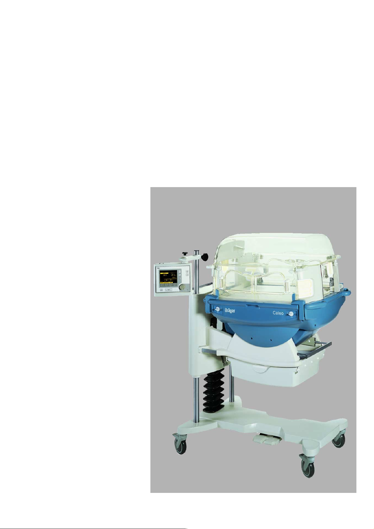
Caleo
Neonatal incubator
Instructions for Use
Software 1.n
®
255 29 515
Page 2
1
How to use the Instructions for Use
The headline ...
specifies the subject of the main chapter
to help you find your way around rapidly.
The page ...
contains instructions for use of the unit
in a combination of text and illustrations. The information is
translated directly into practical actions showing the user
how to use the unit.
The left-hand column ...
contains text
explaining the unit and guiding the user clearly to its uses
through concise instructions in ergonomic sequence.
Dots refer to actions,
●
Numbers refer to the illustration next to the text and to the
sequence of actions in the case of operations consisting of
several steps.
The right-hand column ...
contains illustrations
as a reference to the text and to guide the user in handling the
unit itself. The elements mentioned in the text are highlighted,
and unnecessary details are omitted. The user is guided by
screens confirming the various steps required for each action.
Preparation
Before using for the first time
Preparation
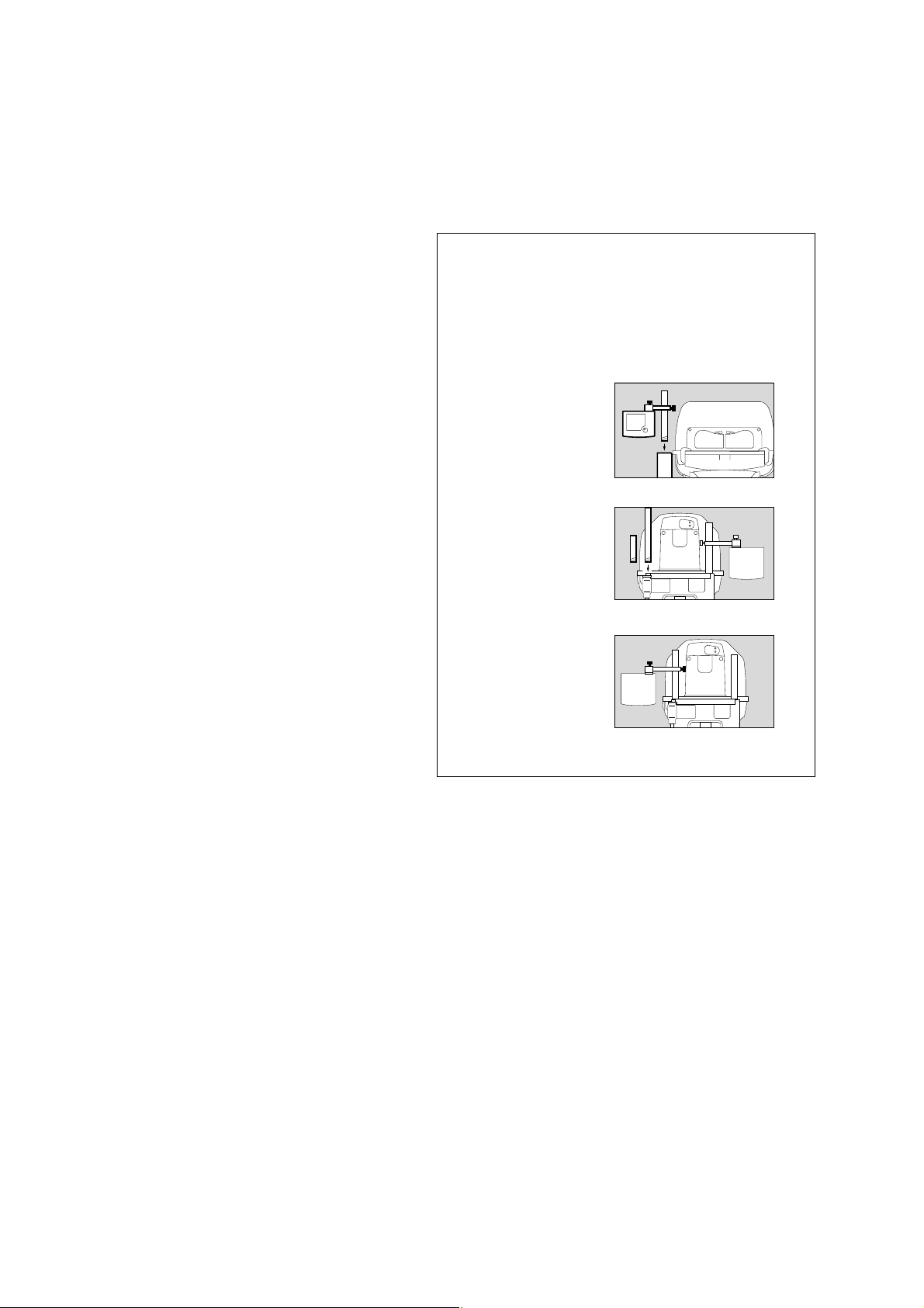
Before using for the first time
● Check that all packaging materials have been completely
removed (see packing slip in the pack).
● Check that the mains power supply voltage matches the
voltage rating specified on the nameplate (see page 123).
● Check that the altitude above sea level is correctly set
(see page 73).
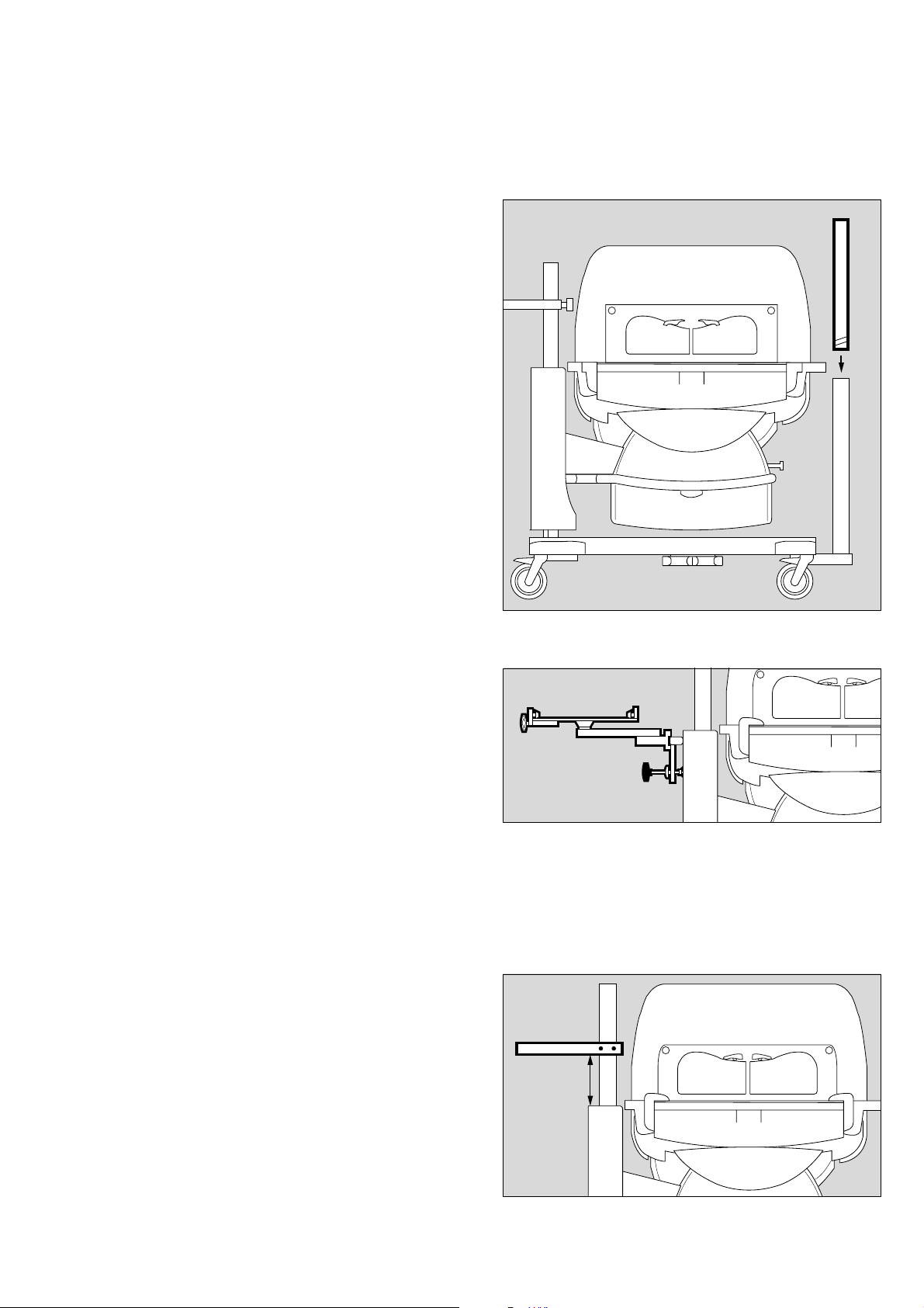
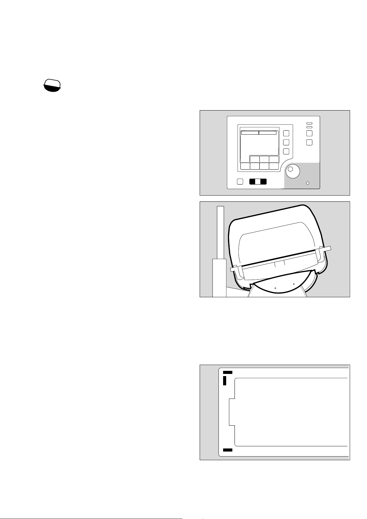
1 Screw the extension pole fully into the base frame and
tighten firmly. Check that it is securely held in place.
2 Slide the holder over the pole and secure it at the required
working height with the clamping screw.
3 Set the control unit to the desired working position and
clamp it securely to the holder with the locking screw.
Make sure that there is sufficient space to swivel and tilt
the control unit!
Fitting accessories
Screw in:
Pole 38 mm/600 (2M 50 691) or alternatively
Pole 38 mm/310 (2M 50 688)
● Remove the cover plate from the base frame.
● Screw the pole fully into the base frame and tighten firmly.
Check that it is securely held in position.
Moving the control unit to the opposite side
4 Remove the control unit = loosen the clamping screw.
5 Remove the holder = loosen the clamping screw.
● Move the holder to the other pole and set to the desired
working height.
5 Fix the holder in position = tighten the clamping screw.
4 Secure the control unit to the holder = tighten the clamping
screw.
12
3
2
1
116 2 9 51 5
228 29 515024 29 515
4
5
14737054
2
Page 3

Contents
Contents
For Your Safety and that of Your Patients 4
Intended use 5
What's what 7
Operating concept 9
Preparation 11
Checking readiness for operation 26
Operation 33
Care 83
Maintenance intervals 94
Troubleshooting – Error Messages 97
Troubleshooting – Faults 102
Technical Data 103
Description 109
Order list 125
Parts List 128
Index 129
3
Page 4

For Your Safety and that of Your Patients
For Your Safety and that of Your
Patients
Strictly follow the Instructions for Use
Any use of the apparatus requires full understanding and strict
observation of these instructions. The apparatus is only to be
used for purposes specified here.
Maintenance
The apparatus must be inspected and serviced regularly by
trained service personnel at six monthly intervals.
Repair and general overhaul of the apparatus may only be
carried out by trained service personnel. We recommend that
a service contract be obtained with DrägerService and that all
repairs also be carried out by them.
Only authentic Dräger spare parts may be used for
maintenance.
Observe chapter "Maintenance Intervals".
Accessories
Do not use accessory parts other than those in the order list.
Not for use in areas of explosion hazard
This apparatus is neither approved nor certified for use in
areas where combustible or explosive gas mixtures are likely to
occur.
Safe connection with other electrical equipment
Electrical connections to equipment which is not listed in
these Instructions for Use should only be made following
consultations with the respective manufacturers or an expert.
Liability for proper function or damage
The liability for the proper function of the apparatus is
irrevocably transferred to the owner or operator to the extent
that the apparatus is serviced or repaired by personnel not
employed or authorized by DrägerService or if the apparatus is
used in a manner not conforming to its intended use.
Dräger cannot be held responsible for damage caused by
non-compliance with the recommendations given above.
The warranty and liability provisions of the terms of sale and
delivery of Dräger are likewise not modified by the
recommendations given above.
Dräger Medical AG & Co. KGaA
4
Page 5

Intended use
Therapy system providing a controlled supply of warmth,
humidity* and O
premature babies and sick neonates up to a body weight of
5 kg or a body length of 55 cm (when treating twins, the total
body weight is limited to 5 kg).
Used in
clinical environment, where premature babies or neonates
need controlled climate parameters.
The unit may only be used by properly trained personnel under
the supervision of qualified medical staff familiar with the
currently known risks and benefits of using an incubator.
2
enrichment* in the patient capsule for
Intended use
Possibilities for nursing and therapy
— Heat therapy through control of air temperature or skin
temperature
— Humidification
—O
2
therapy through controlled O
2
enrichment
— Normal or intensive care via hand ports or a large front flap
— Bed with pivoting adjustment for raising and lowering the
head
With monitoring for
— Air temperature
— Skin temperature
— Relative humidity
—O
2
concentration
— Weight*
* optional equipment feature
5
Page 6

6
Page 7

What's what
What's what
Contents
What's what . . . . . . . . . . . . . . . . . . . . . . . . . . . . . . . . . . . . . . . . . . . . . . . . . . . . . . . . . . . . 8
Front view . . . . . . . . . . . . . . . . . . . . . . . . . . . . . . . . . . . . . . . . . . . . . . . . . . . . . . . . . . . . . . 8
Side view, connections . . . . . . . . . . . . . . . . . . . . . . . . . . . . . . . . . . . . . . . . . . . . . . . . . . 8
Top view, bed . . . . . . . . . . . . . . . . . . . . . . . . . . . . . . . . . . . . . . . . . . . . . . . . . . . . . . . . . . 9
Operating concept . . . . . . . . . . . . . . . . . . . . . . . . . . . . . . . . . . . . . . . . . . . . . . . . . . . . . . 9
Control unit . . . . . . . . . . . . . . . . . . . . . . . . . . . . . . . . . . . . . . . . . . . . . . . . . . . . . . . . . . . . 9
Screen . . . . . . . . . . . . . . . . . . . . . . . . . . . . . . . . . . . . . . . . . . . . . . . . . . . . . . . . . . . . . . . 10
7
Page 8
What's what
What's what
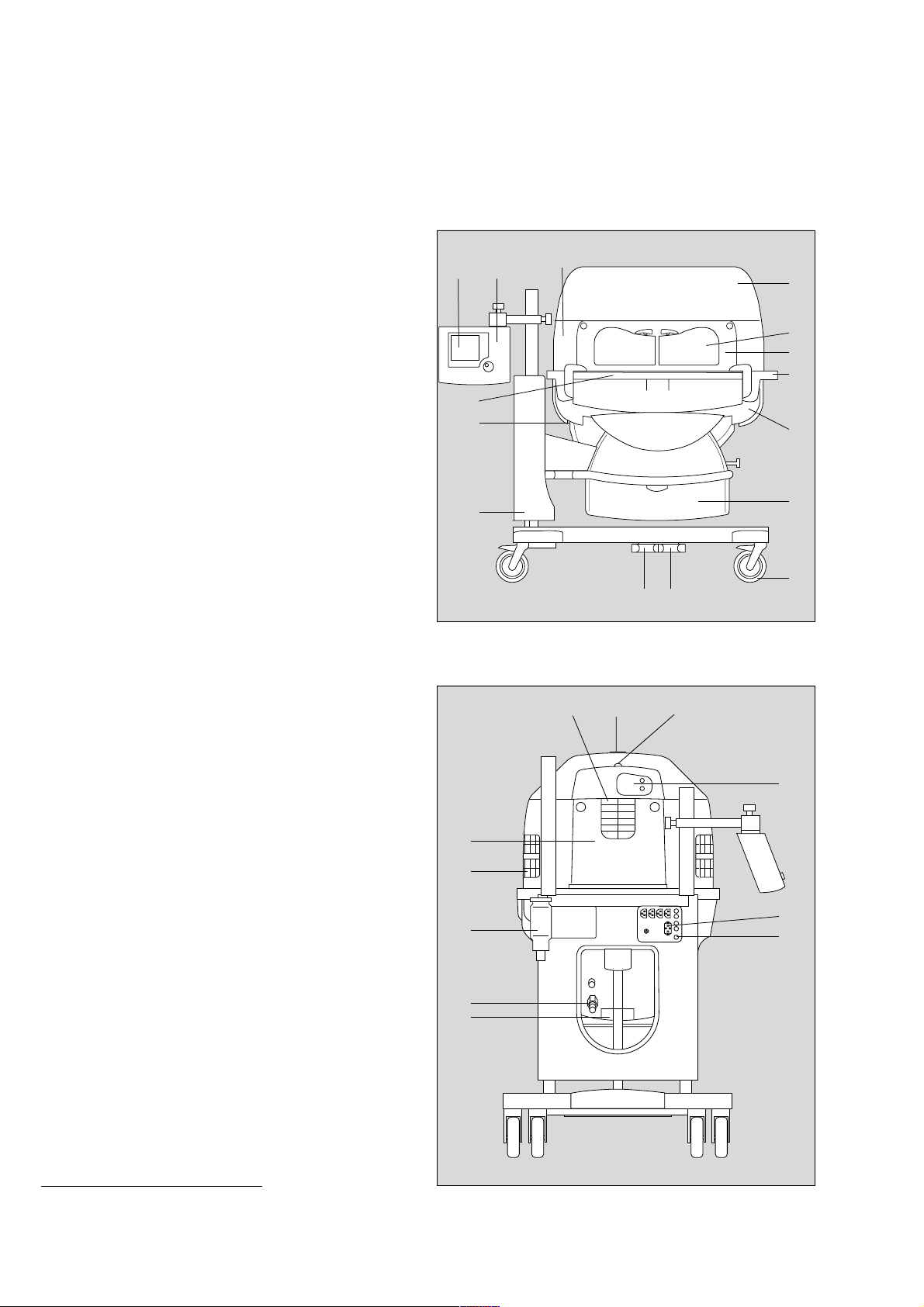
Front view
Canopy
Hand port
Front flap
Handle for transport
Housing
Drawer (2M 50 565)
Castors
Pedals for height adjustment
Height adjustable pillar
Connection for water heater (LuerLock)
X-ray drawer / removable bed
Display
Control unit
Pillar element
*
*
*
/ Housing support
1
2
3
4
5
6
7
8
9
10
11
12
13
14
15
16
17
18
19
20
21
22
23
24
25
13
12
*
11
10
9
14
1
2
3
4
5
6
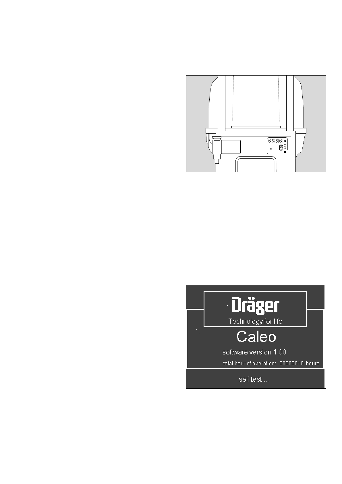
Side view, connections
Central alarm indicator
Sensor unit, temperature connections
Mains power connection
On/off switch
Fresh air filter (MX 17 015)
Connection for O
Water container (2M 50 040)
Tubing grommet (2M 50 385)
Side flap
Tubing port (2M 50 412)
Feeding grommet, hood (2M 50 352)
2
for adjustment
7
88
111 2 9 51 5
152524
16
*
*
23
22
17
21
18
20
19
* optional equipment feature
8
112 2 9 51 5
Page 9
Top view, bed
1
2
: 3
4
5
6
Operating concept
7
8
9
10
12
13
14
15
Spirit levels
Hot air duct
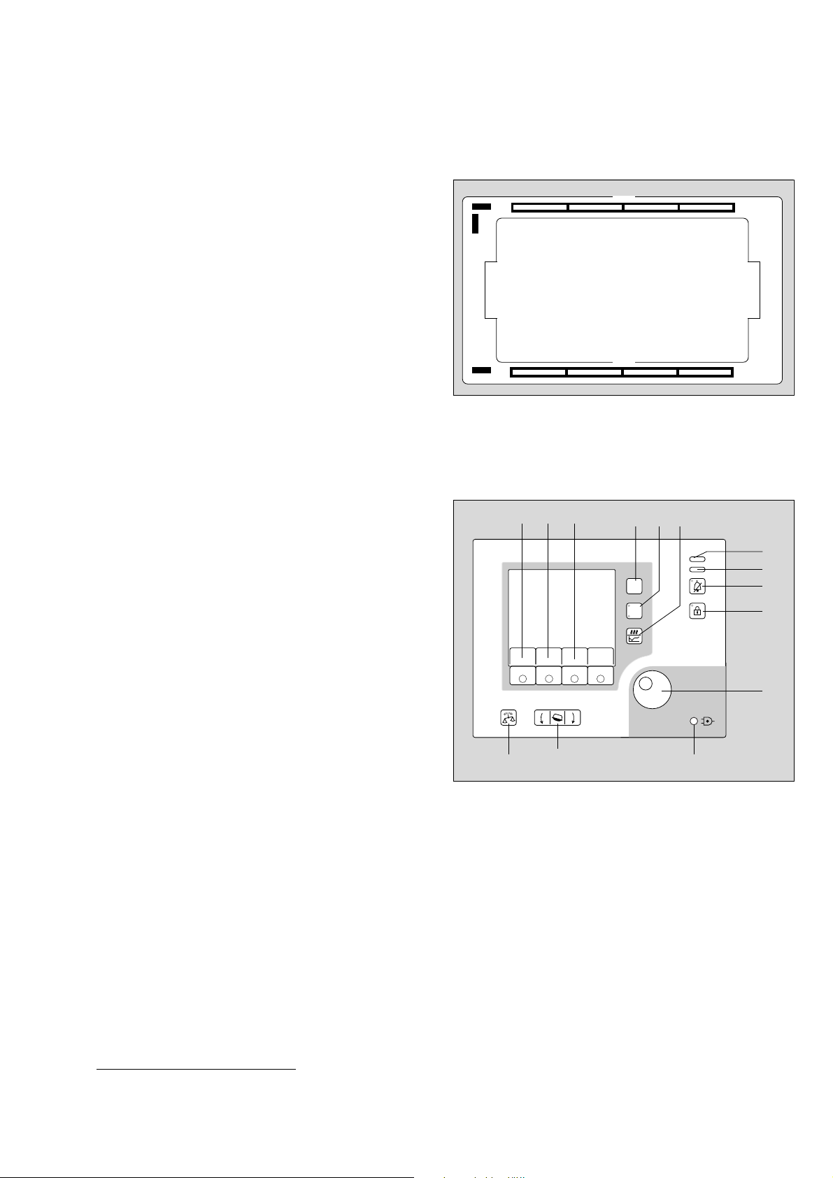
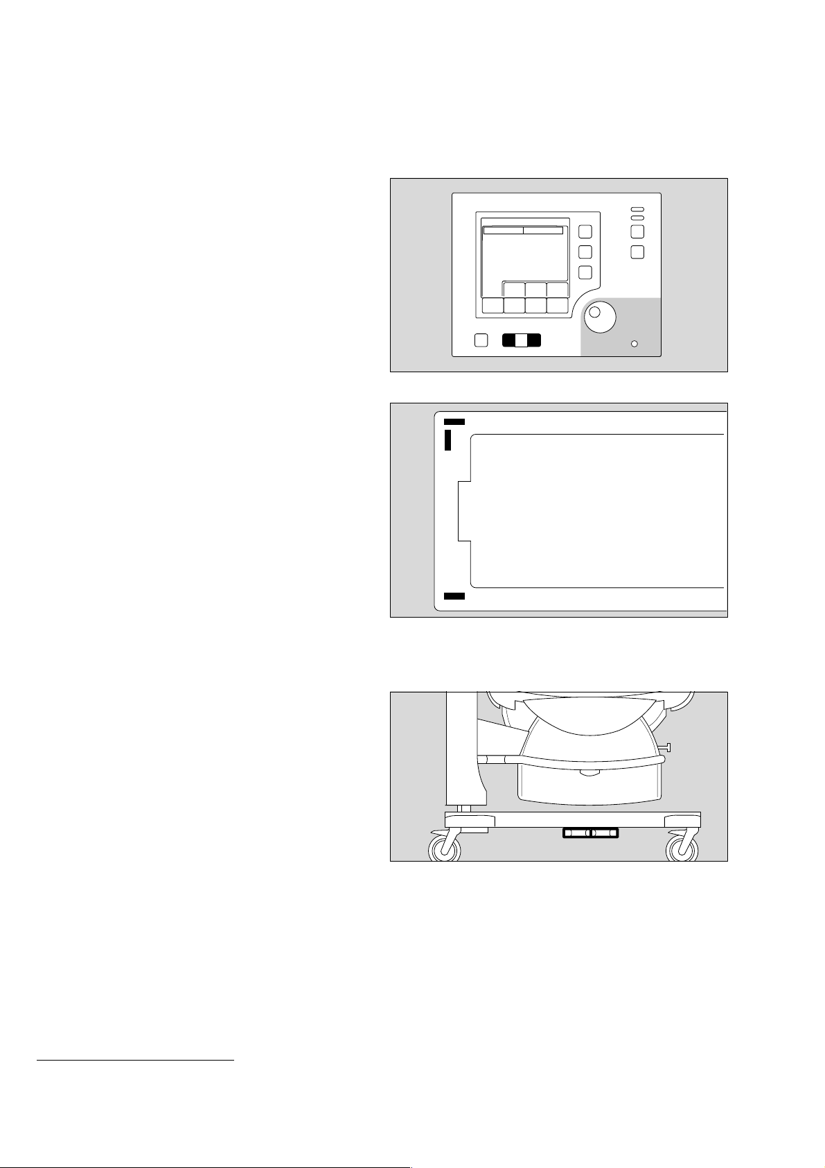
Operating concept
Control unit
Hard Keys
these permanently defined keys enable the user to select
various functions of Caleo
Scales
*
Bed tilt
Menu selection/configuration
Changeover key: air/skin temperature control
Trend display
Suppress alarm tone
Lock key pad function
Rotary knob
®
1
1
1
D
14
15 16
2
2
223 29 515
5
6 7
11
12
Menu
Air
Skin
8
9
Visual signals indicate alarm situations
11 Red alarm LED
Yellow alarm LED
Power failure alarm
Soft Keys
These keys, with variable functions defined by different labels
on the screen, guide the user through the specific routines of
the unit, from preparing for use to shutting down the unit.
Depending on the current menu, different soft keys with
varying functions and labels are activated.
Only the soft keys required for the current menu actually
appear. This precaution keeps the display clear, preventing any
confusion for the user.
When a soft key is pressed, its function is activated and the
relevant menu is displayed on the screen.
In the standard screen, the soft key labels are as follows:
Air/skin temperature
Humidity
16 O2
* optional equipment feature
*
*
10
3
4
13
040 29 515
9
Page 10
Operating concept
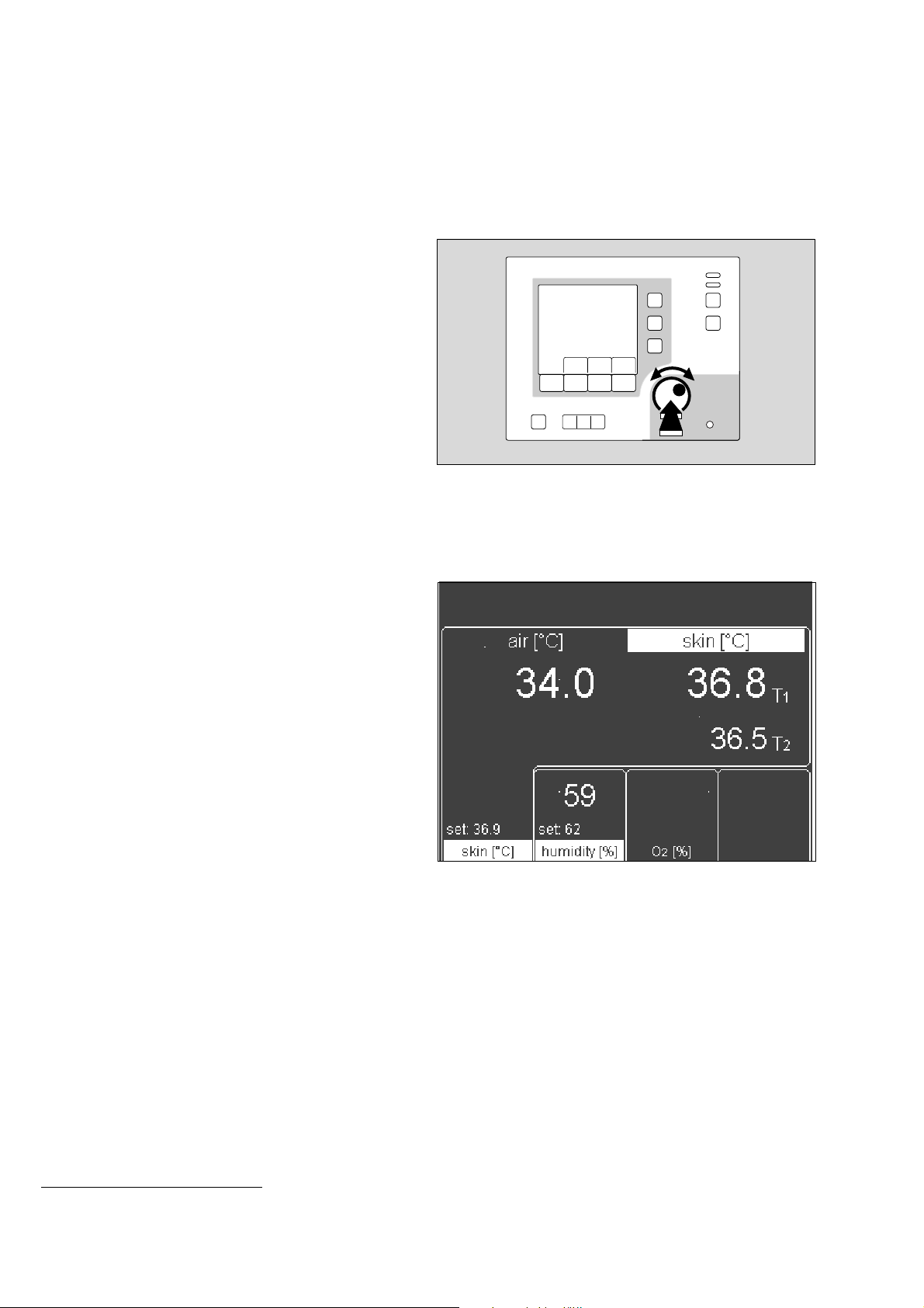
Rotary knob
A single rotary knob is used to select and set parameters.
● Turn knob = select
● Press knob = confirm
D
193 2 9 515
Screen
By default, the measured values are displayed as numeric
values (standard screen).
— Set values and actual measured
values for air temperature/skin temperature
— Set values and actual measured values for relative humidity
— Set values and actual measured values for
O2 concentration
— Alarms and warnings
The screen display can also include a trend graph.
*
*
000 37 054
* optional equipment feature
10
Page 11

Preparation
Preparation
Contents
Preparation . . . . . . . . . . . . . . . . . . . . . . . . . . . . . . . . . . . . . . . . . . . . . . . . . . . . . . . . . . . 12
Before using for the first time . . . . . . . . . . . . . . . . . . . . . . . . . . . . . . . . . . . . . . . . . . . . 12
Fitting accessories . . . . . . . . . . . . . . . . . . . . . . . . . . . . . . . . . . . . . . . . . . . . . . . . . . . . . 12
Doors, ports and bed . . . . . . . . . . . . . . . . . . . . . . . . . . . . . . . . . . . . . . . . . . . . . . . . . . . 18
Checking readiness for operation . . . . . . . . . . . . . . . . . . . . . . . . . . . . . . . . . . . . . . . . 26
Before using for the first time . . . . . . . . . . . . . . . . . . . . . . . . . . . . . . . . . . . . . . . . . . . . 26
Before each use . . . . . . . . . . . . . . . . . . . . . . . . . . . . . . . . . . . . . . . . . . . . . . . . . . . . . . . 26
11
Page 12
Preparation
Before using for the first time
Preparation
Before using for the first time
● Check that all packaging materials have been completely
removed (see packing slip in the pack).
● Check that the mains power supply voltage matches the
voltage rating specified on the nameplate (see page 123).
● Check that the altitude above sea level is correctly set
(see page 73).
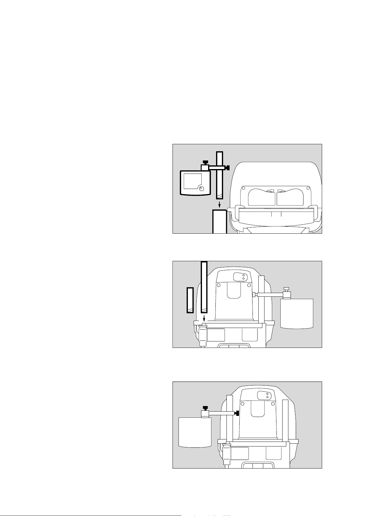
1 Screw the extension pole fully into the base frame and
tighten firmly. Check that it is securely held in place.
2 Slide the holder over the pole and secure it at the required
working height with the clamping screw.
3 Set the control unit to the desired working position and
clamp it securely to the holder with the locking screw.
Make sure that there is sufficient space to swivel and tilt
the control unit!
3
2
1
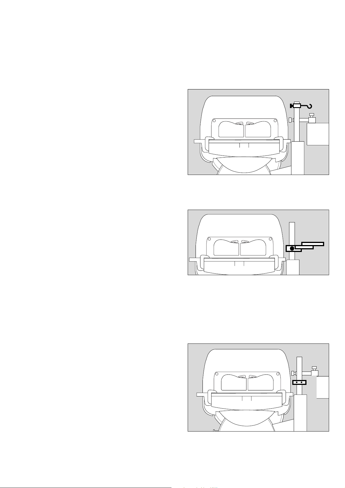
Fitting accessories
Screw in:
Pole 38 mm/600 (2M 50 691) or alternatively
Pole 38 mm/310 (2M 50 688)
● Remove the cover plate from the base frame.
● Screw the pole fully into the base frame and tighten firmly.
Check that it is securely held in position.
Moving the control unit to the opposite side
4 Remove the control unit = loosen the clamping screw.
5 Remove the holder = loosen the clamping screw.
● Move the holder to the other pole and set to the desired
working height.
5 Fix the holder in position = tighten the clamping screw.
4 Secure the control unit to the holder = tighten the clamping
screw.
116 2 9 5 15
228 29 515024 29 515
4
5
12
Page 13
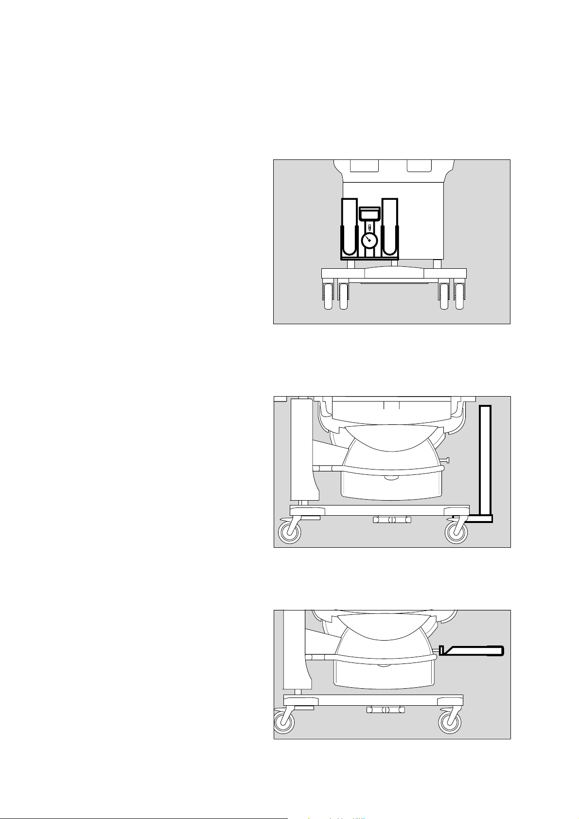
Infusion support (2M 21 514)
for pole, 38 mm
● Place the fixing clamp on the stand pillar.
● Push the infusion support into the clip and secure by
tightening the clamping screw.
Preparation
Fitting accessories
010 2 9 515020 29 515101 29 515
Swivel table (2M 21 186)
For small articles, max. load 3 kg, for mounting on 38 mm pole
● Place the clamp of the swivel table on the stand pillar and
tighten the clamping screw.
Make sure that the table has space to swivel freely!
Compact rail (2M 85 337)
Max. load 5 kg, for mounting on 38 mm pole
This rail must only be mounted by qualified technical staff!
For holding accessories, e.g.
—O2 monitor
● Adjust the height of the compact rail to the required height
of the mounted accessory.
1 Fit the compact rail to the pole = push the compact rail over
the pole and
2 fasten with the screws.
1
2
13
Page 14
Preparation
Fitting accessories
Bronchial aspiration system (2M 85 125)
Follow the separate Instructions for Use of the bronchial
aspirator.
● Fix the bronchial aspirator holder to the standard rail on the
wall side or handle side.
● Tighten the clamping lever.
● Establish the hose connections.
Basic pole (2M 50 680)
Maximum load 5 kg
This pole must only be mounted by qualified technical
staff!
For fixing accessories, e.g.
— additional pole extensions (see page 15).
— swivel table (2M 21 186)
— monitor support plate (2M 50 085)
● Fix to the unit in accordance with the separate Assembly
Instructions.
Tray 3020 (M 24 678)
Maximum load must not exceed 2 kg!
230 29 515
019 29 515021 29 515
● Hang the tray from the standard rail on the wall or handle
side and secure in position.
14
Page 15
Pole extensions
The following poles can be fixed to the base pole as extension:
— Pole 38 mm/600 (2M 50 691) or
— Pole 38 mm/310 (2M 50 688) or
— Pole 25 mm/600 (2M 50 689).
● Screw the pole into the base pole as far as it will go and
tighten securely. Make sure that it is securely held in place.
Preparation
Fitting accessories
Notebook holder (2M 22 171)
Maximum load must not exceed 3 kg!
1 Fix the holder to the handle rail of the Caleo®.
2 Align the holder horizontally with the clamping screw.
● Check that the holder is securely fixed in position and that
the swivelling mechanism is functioning correctly by turning
and tilting the support plate.
Monitor shelf (2M 50 085)
Maximum load must not exceed 20 kg!
Shelf for monitor and ventilation equipment.
This shelf must only be mounted by qualified technical
staff!
To fix the monitor shelf, fit a second 38 mm pole
(see page 12).
● Fit the monitor holder = slide the plate over both 38 mm
poles and
3 fix in position with the screws.
The distance between the monitor shelf and the base
frame must not exceed 20 cm.
max. 20 cm
229 29 515022 29 515
1
2
3
15
023 29 515
Page 16
Preparation
Fitting accessories
Hose holder for ventilation hoses (84 11 075)
● Open the front flap.
● Raise the bed and pull it out of the incubator.
● Push the mattress slightly to one side.
● Place the hose holder in the mounting hole in the bed and
fasten from underneath with the locking screw.
● Replace the bed in the incubator and close the front flap.
The hose holder can be fixed to any of the four corners of the
bed.
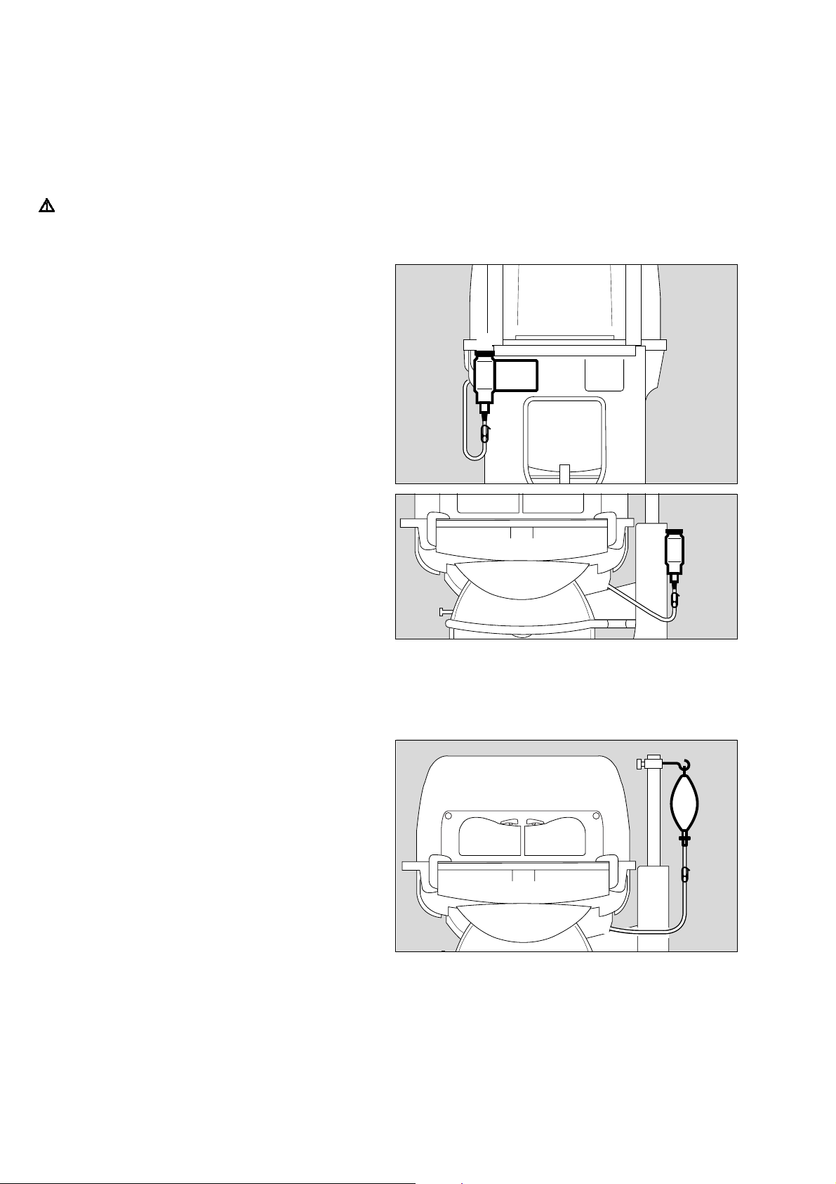
1 Clip the ventilation hoses and cables into the clips at the
end of the ventilation hose holder.
11
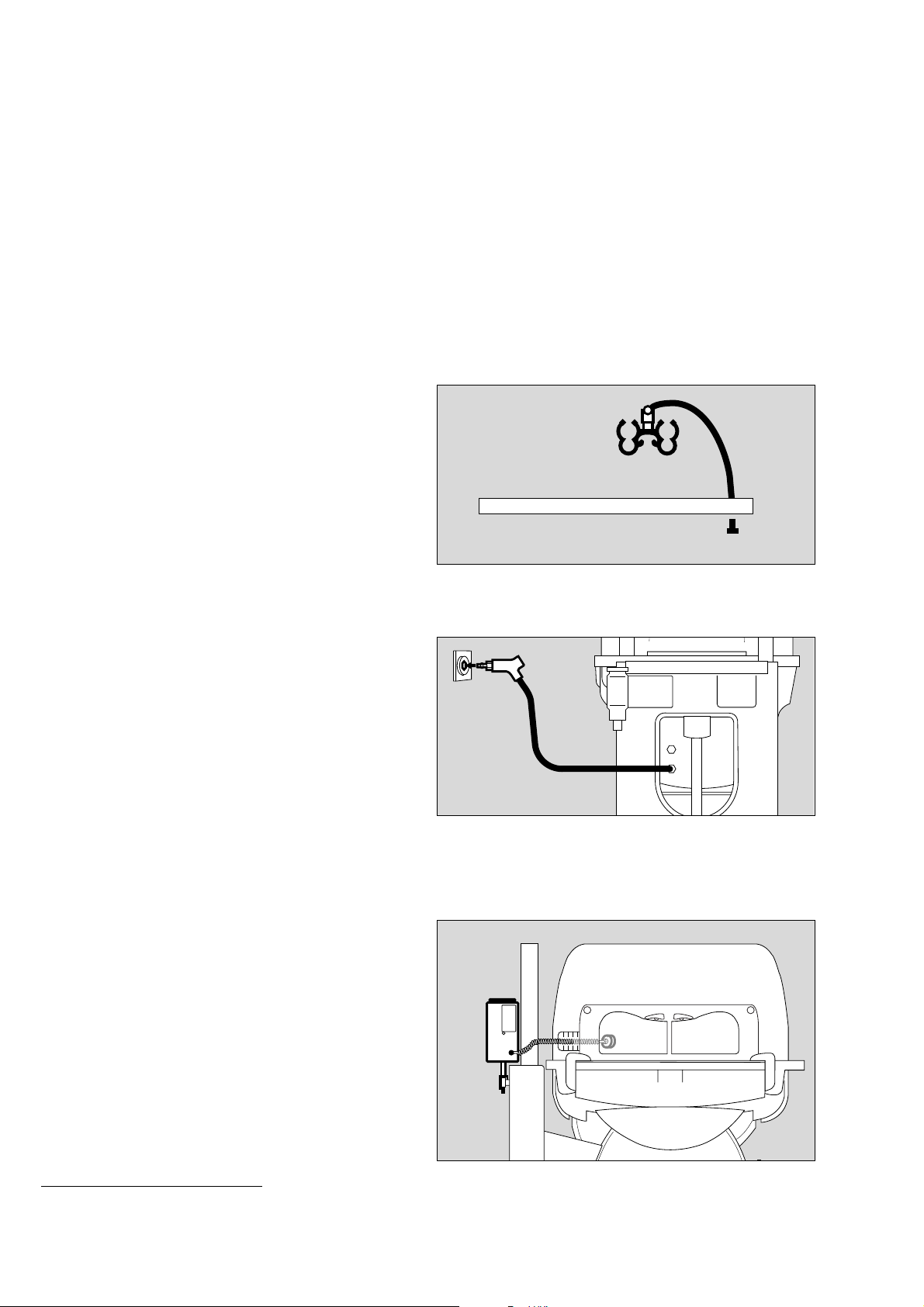
O2 enrichment with O2 control
*
2 Screw the O2 connecting hose into the port underneath the
incubator.
● Connect the probe to the outlet of the central O2 supply
pipeline in the "park" position (see separate Instructions for
Use).
The maximum gas pressure must be 500 kPa.
O2 monitor
To monitor the O2 concentration, use an O2 monitor that has
alarm limits:
● Fix the O2 monitor to the handle rail with the holder.
● Place the sensor capsule in Caleo
● Route the sensor cable through one of the flexible tubing
®
.
ports. Where applicable, push the sensor plug into the
socket of the O2 monitor (e.g. Oxydig or MiniOx) until it
audibly clicks into place (see separate Instructions for Use
2 monitor).
of O
008 29 515
2
011 29 515
* optional equipment feature
16
028 29 515
Page 17
Vacuum mattress (2M 17 909)
The contour of the vacuum mattress can be altered as required
and is then maintained after air evacuation of the mattress.
Extreme positions can therefore be obtained for special
applications. The foam mattress can remain in the incubator.
● Open the front flap.
● Insert and preform the vacuum mattress.
● Place the patient on the mattress and finally adjust the
mattress to the desired shape.
● Connect the vacuum mattress to the hose of the suction
system.
1 Open the valve and evacuate the vacuum mattress.
1 Close the valve and disconnect the hose.
● Close the front flap.
Preparation
Fitting accessories
1
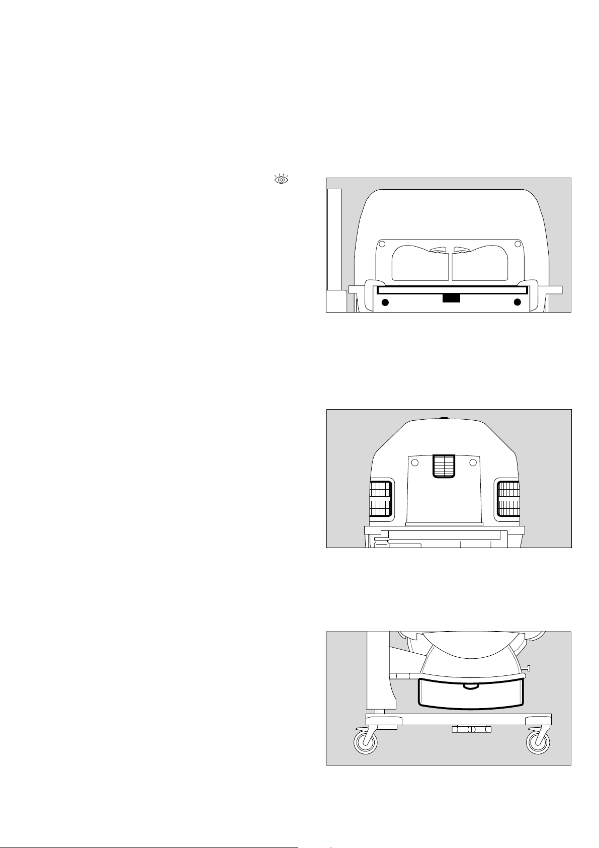
Fitting the drawer (2M 50 565)
Maximum load must not exceed 7 kg.
● Fit the drawer = slide the drawer box into the groove in the
base frame.
213 2 9 515
118 29 515
17
Page 18
Preparation
Doors, ports and bed
Doors, ports and bed
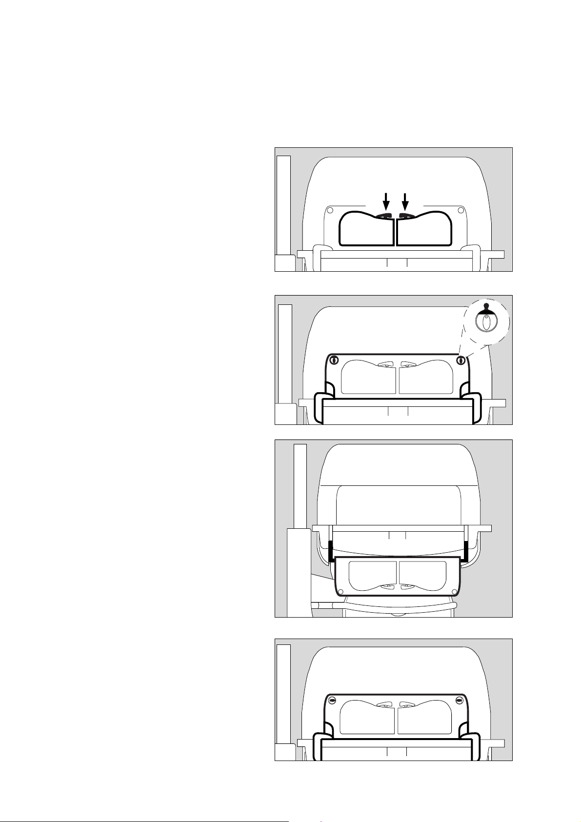
Hand ports
To open the hand ports:
1 Press the catch: the relevant hand port swings open.
To close the hand ports:
● Push the hand ports back into place until the catch
engages.
Front flap
To open the front flap:
2 Turn the two knobs inwards to the vertical position.
The red latch becomes visible.
11
014 29 529
● Lower the front flap until it hangs down vertically towards
the floor.
Avoid pinching or jamming hoses and cables in the removable
double wall!
To close the front flap:
● Raise the front flap and press into position,
3 Turn the two knobs outwards to the horizontal position until
you feel them click into place.
2
2
015 2 9 515
016 2 9 515091 29 515
Make sure that both knobs are engaged in position!
The red latches must no longer be visible!
18
3
3
Page 19
Side flap
● The side flap is opened and closed in the same way as the
front flap (see page 18).
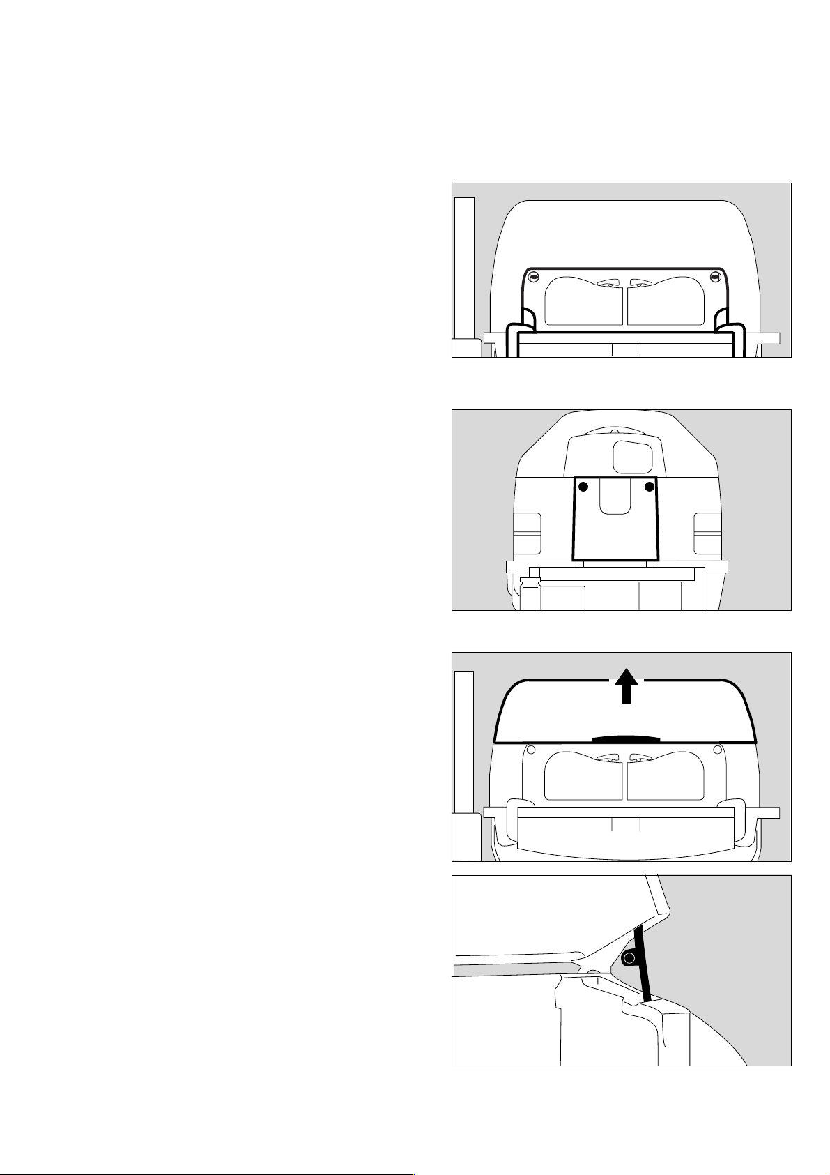
Canopy
To open the canopy:
1 Grasp the handle on the canopy
and
2 lift open (approx. 60o).
Preparation
Doors, ports and bed
231 29 515104 2 9 515
2
Do not tilt the canopy forwards!
3 Raise the side support prop, and lower the canopy until the
prop is fixed in the slot of the canopy.
To close the canopy:
1 Grasp the handle on the canopy and raise it slightly.
3 Fold down the prop
and
● close the canopy.
The canopy can be opened from both sides.
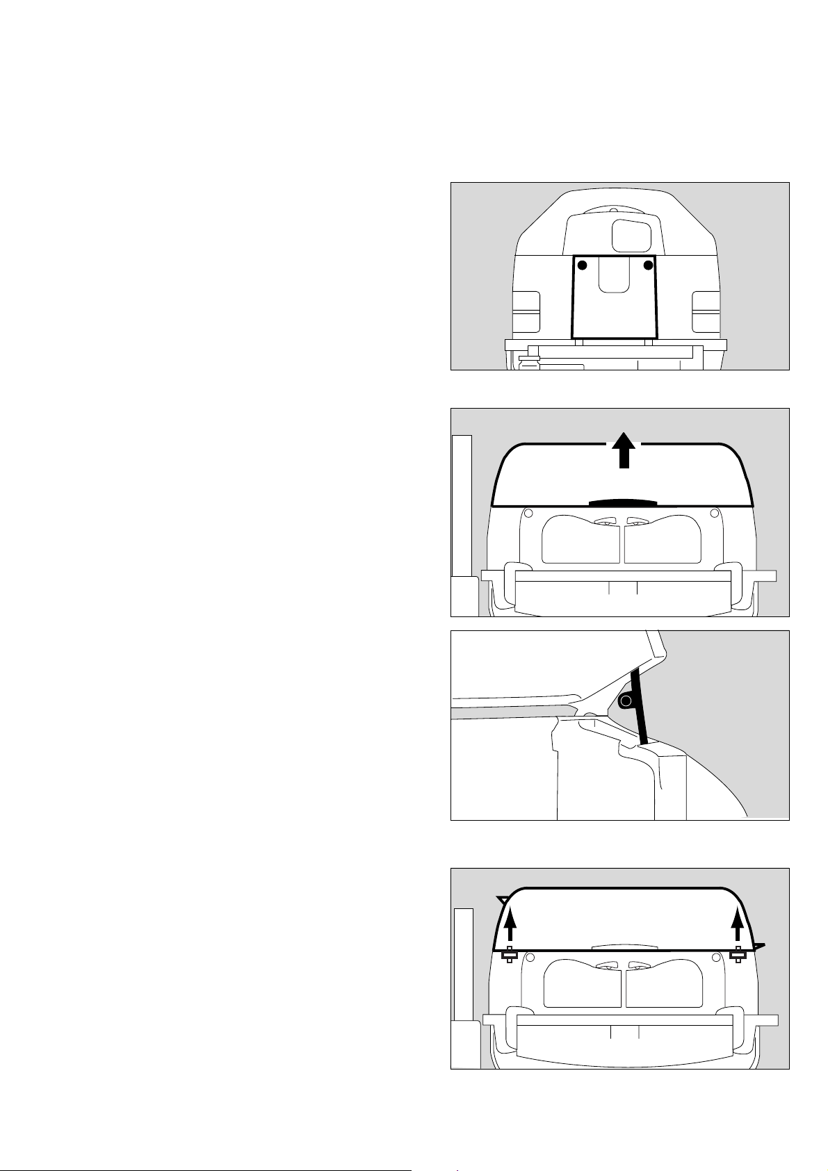
To remove the canopy:
4 Grasp the handles on the sides of the canopy with both
hands.
5 Lift the canopy horizontally off the pillar elements.
1
3
196 2 9 515
4
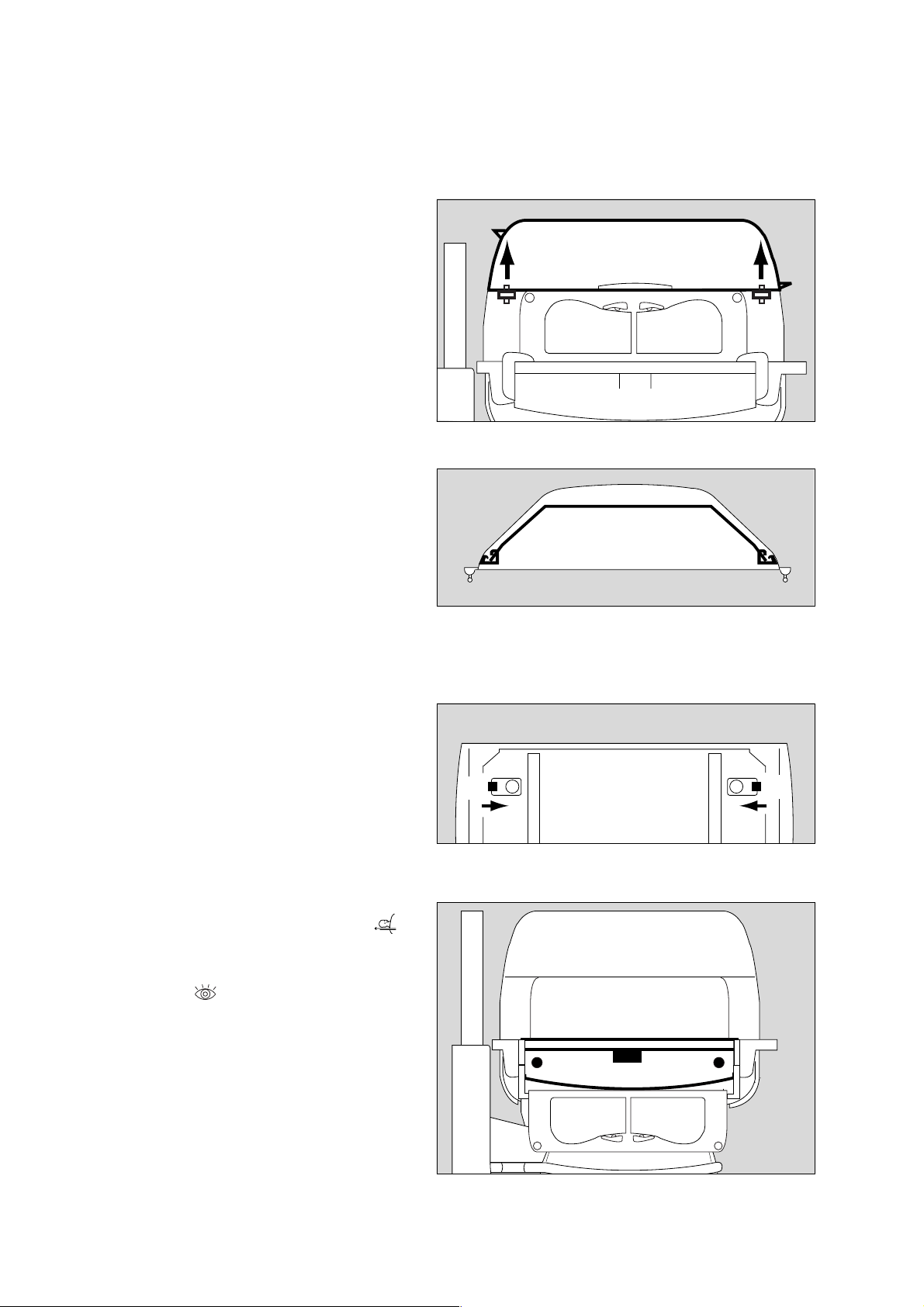
To replace the canopy:
5 Replace the canopy horizontally, so that the guide pins fit
into the holes in the pillar element.
Take care with the sensor unit!
4
55
093 29 515
19
Page 20
Preparation
Doors, ports and bed
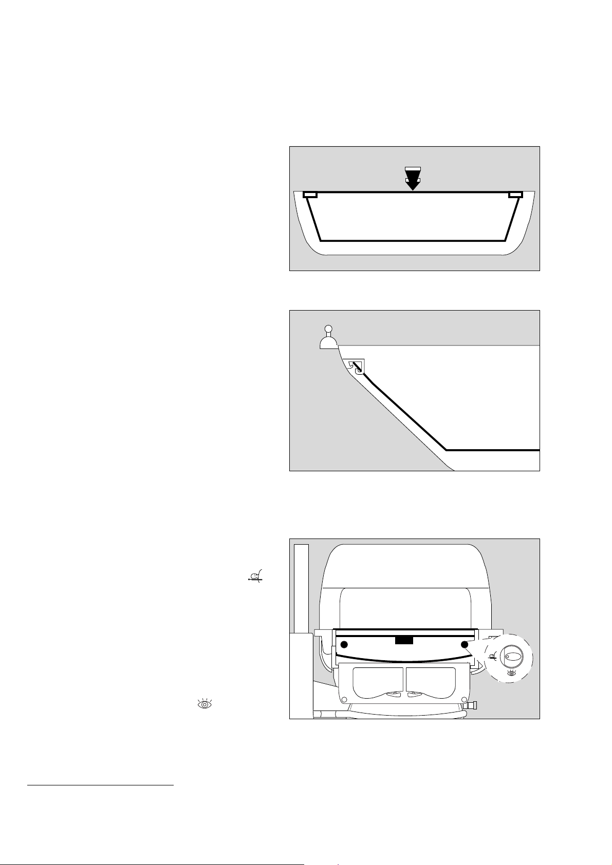
Double wall
*
To remove the double wall:
● Remove the canopy and lay it upside down (on a soft,
non-abrasive surface).
1 Squeeze the double wall inwards slightly, and
2 release the oblong holes of the double wall from the
retaining lugs in the canopy.
● Pull the double wall out of the canopy.
To install the double wall:
● Place the canopy upside down (on a soft, non-abrasive
surface).
● Insert the double wall in the canopy.
3 On one longitudinal side, fit the retaining lugs of the canopy
into the oblong holes of the double wall.
● Squeeze the double wall inwards slightly and fit the
retaining lugs on the second longitudinal side of the canopy
into the oblong holes of the double wall.
● Turn the canopy the right way up again.
The retaining lugs of the canopy must remain seated in the
oblong holes.
2
2
1
149 29 515
3
Removing the bed
Maximum load must not exceed 5 kg
● Open the front flap and fold it down.
Pull the bed out:
4 Set both knobs horizontally to the position marked ,
5 Pull the bed out towards the front as far as it will go, holding
it by the recessed handle or by the knobs.
When the bed is pulled out, monitor the patient constantly
to prevent the risk of a fall.
Do not lean or rest any weight on the bed when it is pulled
out.
● After completing the care procedure, push the bed back in
until it engages. Turn the knobs to the position and
close the front flap.
Push the bed all the way in! Otherwise the hot air duct will
be interrupted, and the patient may be warmed or cooled
excessively!
4 4
5
252 29 515
187 29 515
* optional equipment feature
20
Page 21
Using the X-ray drawer
The X-ray drawer can be pulled out when the front flap is either
open or closed.
To open the X-ray drawer:
1 Set both knobs vertically to the position marked ,
2 pull the drawer out by the recessed handle or the knobs.
● Insert or remove the X-ray cassette. Recesses are provided
in the X-ray drawer for positioning.
Do not use the X-ray drawer as a writing support or bed for
the patient.
To close the X-ray drawer:
2 push the drawer inwards under the bed until it tangibly
clicks into place.
Push the X-ray drawer in fully! Otherwise the hot air duct
will be interrupted, and the patient may be warmed or
cooled excessively!
Preparation
Doors, ports and bed
1
2
1
017 29 515
Sealed through-holes
3 Tubing ports (2M 50 412)
4 Tubing grommets (2M 50 385)
5 Feeding grommet, hood (2M 50 352)
● Route the cables or hoses through the flexible grommets
and sleeves.
To route ventilation hoses and cables through the Caleo®, use
the ventilation hose holder (page 16).
Drawer (2M 50 565)
Drawer for storing items required for nursing or treatment.
The drawer is accessible from both sides.
Open the drawer:
6 grasp the drawer by the handle and pull it out as far as it
will go.
● Place the required material in the drawer.
5
3
44
095 29 515
Close the drawer:
6 push the drawer back in by the handle.
6
013 29 515
21
Page 22
Preparation
Doors, ports and bed
Trolley (base frame) with variable height adjustment
*
To use the height adjustment facility:
● Switch on Caleo
®
(see page 37).
1 Press the left pedal – Caleo® is lowered.
2 Press the right pedal – Caleo® is raised.
● Adjust to a comfortable working height.
When the height stops changing, the frame is at its end
position. Release the pedal.
Hoses and cables must be long enough so that they do not
kink, tear or become squashed!
Do not store anything under the drawer!
The height adjustment and tilt angle adjustment cannot be
operated at the same time!
The height adjustment can only be operated for
max. 6 minutes during one hour.
1 2
009 29 515
* optional equipment feature
22
Page 23
Tilting the bed
Preparation
Doors, ports and bed
To tilt the bed:
● Switch on Caleo
®
(see page 37).
1 Press button = raise the bed on the control unit side.
2 Press button = lower the bed on the control unit side.
● Adjust the bed to the required tilt angle.
The end position is reached when the tilt angle stops
changing. Release the button.
®
The entire housing of the Caleo
incubator is tilted.
Hoses and cables must be carefully routed so that they do
not kink, tear or become squashed!
The height adjustment and tilt angle adjustment cannot be
operated at the same time!
Do not reach in between the housing and housing support
during adjustment. Danger of injury!
D
1
2
214 29 515
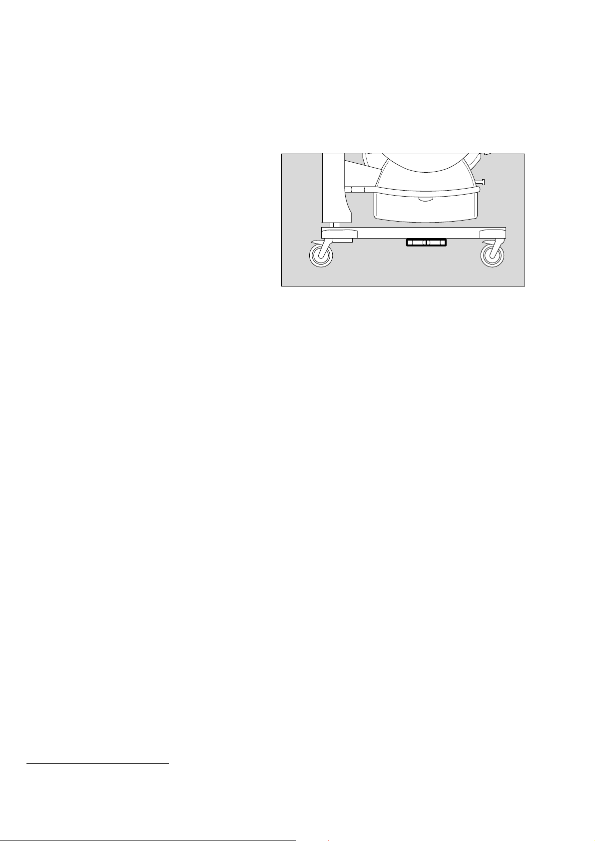
Setting the bed to the horizontal position
● Caleo
®
must be switched on (see page 37).
1 Press button = the bed will be raised on the control unit
side.
2 Press button = the bed will be lowered on the control unit
side.
The spirit levels show whether the bed is horizontal.
3 Spirit levels for the horizontal position of Caleo® in the
transverse axis.
®
4 Spirit level for the horizontal position of Caleo
in the
longitudinal axis. When using the integrated scales
(optional, see "Weighing scale" on page 78), make sure
that the unit is on a flat floor before setting.
086 29 515
3
4
3
242 2 9 515
23
Page 24
Preparation
Doors, ports and bed
Using humidifier systems
Use only sterilised Aqua dest.!
Water container (2M 50 040):
● Disinfect hands.
1 Open the water container = lift up the cap.
● Fill the water container with sterilised Aqua dest.
Do not use any additives!
Capacity: 2.8 L (note level marks)
1 Close water container = push down the cap.
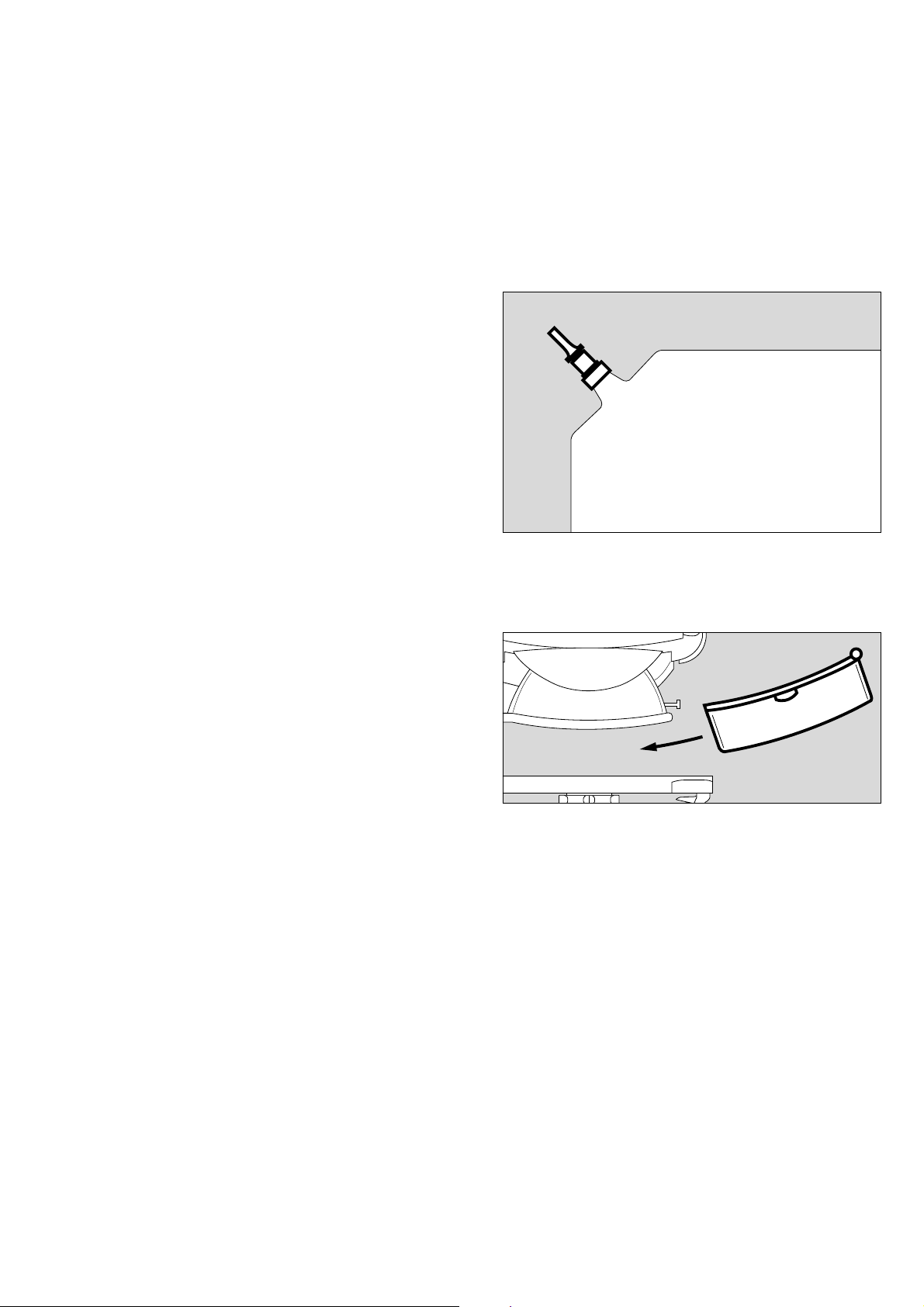
● Prepare a fresh connection tube (MX 17 018).
2 Close the clamp on the connection tube.
3 Pierce the silicone nozzle of the water container with the pin
of the connection tube.
2 Open the clamp on the connection tube.
● Bleed the connection tube (let distilled water drain off).
2 Close the clamp on the connection tube.
4 Connect the LuerLock connection to the water connection
pipe.
5 Open the clamp on the connection tube.
● Switch on the humidification module on Caleo
®
and set the
humidity value (page 51).
1
3
2
097 29 515
4
5
Water bag:
Use only sealed bags with sterilised Aqua dest.!
Do not use any additives!
Must not be confused with infusion solutions!
● Disinfect hands.
● Prepare a new connection tube (MX 17 018) and a water
bag with sterilised Aqua dest.
6 Close the clamp on the connection tube.
● Insert the pin of the connection tube into the connector of
the water bag.
6 Open the clamp on the connection tube.
● Bleed the connection tube (let distilled water drain off).
6 Close the clamp on the connection tube.
7 Connect the LuerLock connection to the water connection
pipe.
6 Open the clamp on the connection tube.
● Switch on the humidification module on Caleo
®
and set the
humidity value (page 51).
Replacing the water bag:
Distilled water bag empty = the water shortage alarm on
®
Caleo
is triggered.
● Disinfect hands.
● Close the clamp on the connection tube.
● Replace the water bag and reopen the clamp.
185 2 9 515
6
7
098 29 515
24
Page 25

25
Preparation
Doors, ports and bed
Integrated socket strip
The integrated socket strip can be used to connect
— infusion pumps and
— SpO
2
measuring equipment.
Connections may only be made by qualified technical staff.
Caleo does not monitor the power supply to external devices.
[
Do not exceed the maximum power input of the
connected accessories (all 4 sockets together: max. 2A).
The maximum permissible total leakage current must not
be exceeded. For the leakage current of Caleo
®
without
099 29 515
socket strip, see "Technical Data" on page 104.
Page 26

Checking readiness for operation
Before using for the first time
Checking readiness for operation
Before using for the first time
● Check that the mains voltage supply corresponds to the
voltage rating on the nameplate (see page 123).
● Check that the altitude above sea level is correctly set
(see page 73).
Before each use
● Check that the equipment has been disinfected and
cleaned in accordance with the conditions laid down by the
hospital (see "Disinfecting/Cleaning/Sterilising" on
page 84).
● Check that an adequate gas supply is available for the
equipment to be used.
● Check that the required accessories and therapy
equipment are available and in perfect condition.
Only use parts that have been stripped down and sterilised.
Check readiness for operation in accordance with the
relevant Instructions for Use.
● Check that there are no cracks or sharp, chipped edges on
the incubator canopy.
● Check that the hinges and catches on the canopy are in
proper working order.
● Check that the cables and hoses have been routed
correctly and safely.
● Check that there is sufficient space for adjusting the tilt and
height.
● Connect to the mains supply.
● Check that the slits of the sensor unit are not fouled.
Do not use multiple-plug adapters for the Caleo® power
supply!
The patient leakage current may rise above the permitted
limits if the protective earth conductor fails when equipment
is connected to the socket strip. The risk of electric shocks
cannot be excluded in such cases.
Before using the unit, make sure that the following tests have
been performed:
Disinfect hands before each test!
Check that the hand ports are secure
1 Open hand port = press catch
● Close hand port until the catch engages.
● Pull the edge of the hand port – it must not open.
If the hand port fails to remain engaged:
● Call DrägerService.
11
014 29 529
26
Page 27
Check that the front flap is secure
● Open the front flap and fold it down (see page 18).
1 Raise and press the flap closed and turn the two knobs
outwards until they tangibly engage in the horizontal
position.
Checking readiness for operation
Before each use
Make sure that both knobs are engaged!
The red latches must no longer be visible!
If the front flap fails to remain engaged or if the red latches are
visible:
● Call DrägerService.
Check that the side flap is secure
● Open the side flap and fold it down (see page 19).
2 Fold up the side flap and press it closed. Turn the two
knobs outwards until they tangibly engage in the horizontal
position.
Make sure that both knobs are engaged!
The red latches must no longer be visible.
If the side flap fails to remain engaged or if the red latches are
visible:
● Call DrägerService.
Check that the canopy is secure
3 Grasp the handle and open the canopy.
4 Lift open the flap (approx. 60o).
1
1
090 29 515
22
189 2 9 515
4
5 Raise the side prop.
● Lower the canopy until the prop is secured in the slot of the
canopy.
If the canopy fails to remain open:
● Call DrägerService.
3
224 29 515
5
225 29 515
27
Page 28
Checking readiness for operation
Before each use
1 Grasp the handles on the sides of the canopy with both
hands.
2 Lift the canopy horizontally off the pillar elements.
1
If the canopy holders are damaged:
● Call DrägerService.
Check that the double wall is securely in place
● All 4 retaining lugs in the canopy must be seated in the
oblong holes of the double wall.
If the double wall or the retaining lugs in the canopy are
damaged:
● Call DrägerService.
Check that the trough is secure
● Remove the canopy.
● Remove the mattress.
● Remove the bed.
3 Check the catches of the trough.
● Place the bed on the trough.
● Place the mattress on the bed.
● Refit the canopy.
1
22
226 29 515
135 2 9 515136 2 9 515
If the catches for the trough are damaged:
● Call DrägerService.
Remove the bed
● Open the front flap and fold it down.
4 Set both knobs horizontally to the position marked ,
5 Grasp the bed by the recessed handle or by the knobs and
pull it out towards the front as far as it will go.
5 Push the bed back until it clicks into place,
4 turn the knobs to the position.
● Close the front flap.
If the bed cannot be pulled out or pushed in or if the knobs are
damaged:
● Call DrägerService.
If the bed is not fully pushed in, the hot air duct will be
interrupted, causing the control system to malfunction!
The result may be excessive cooling or overheating of
the patient!
3
4
5
4
3
018 29 515
28
Page 29
Activate the self-test, check audible warning tone
1 Switch on the unit = press the on/off switch until it clicks
into position.
Checking readiness for operation
Before each use
1
During the self-test, the functions of the machine are checked.
The audible signal, alarm beep sequence, screen displays and
LEDs must be checked by the user.
— An audible warning signal and an alarm beep sequence are
sounded.
If the warning signal or alarm beeps are not sounded,
● Call DrägerService.
— The screen and LEDs initially go dark and are then lit.
If individual pixels fail to light up or screen images are burnt, or
if the LEDs fail to light up,
● Call DrägerService.
— The opening screen is displayed.
If the opening screen is not displayed,
● Call DrägerService.
110 2 9 5 15
The unit is switched on.
04237054
29
Page 30
Checking readiness for operation
Before each use
Check the bed tilting mechanism
1 Tilt the bed.
During the tilting process, the entire housing of the Caleo
must move uniformly. If not:
● Call DrägerService.
Do not reach in between the housing and the housing
support while the unit is moving! Risk of injury!
®
D
1
2
2 Return the bed to the horizontal position (see page 23).
● The spirit levels in the bed show whether the bed is
horizontal. This check is especially important when using
the built-in weighing scales (see page 78)!
If the spirit levels are damaged:
● Call DrägerService.
Check the height adjustment mechanism
● Operate both foot pedals in succession to raise and lower
*
the Caleo® (see page 22).
● Then adjust to a comfortable working height.
When adjusting the height, the entire housing of the Caleo®
must rise or descend uniformly. If not:
● Call DrägerService.
132 2 9 515
253 29 515
* optional equipment feature
30
089 29 515
Page 31

Check the power failure alarm
● Disconnect the unit from the mains.
1 The power failure LED must flash.
An intermittent tone must start. The volume of this tone must
remain constant for at least 30 seconds.
If the volume decreases too soon:
● Leave the incubator connected to the mains and switched
on for 24 hours to recharge the NiCd battery.
● Repeat the test.
If the volume again decreases too soon:
● Call DrägerService.
Check the fresh air filter
● Tilt the unit to remove the fresh air filter more easily
(see page 23).
Checking readiness for operation
Before each use
D
1
133 2 9 515
2 Pull the holder for the fresh air filter downwards and remove
If no filter is installed:
● Install the filter.
● Mark the date of first use on the label of the new filter and
affix the label to the side of the filter.
If a filter is already installed:
● Remove the filter and check the date of use. The label is on
the edge of the filter.
● Replace the filter if fouled or damaged.
If the filter is more than 2 months old:
Separate the filter frame and filter holder at the snap-in
fastening and replace the old filter by a new filter.
● Mark the date of first use on the label of the new filter and
affix the label to the edge of the filter.
Before operating the unit with skin temperature sensors, it is
important that the sensors must be tested before they can be
used on the unit (see "Using skin temperature control" on
page 42).
211 29 515124 2 9 515
2
The incubator is ready for operation when all
checks have been carried out successfully.
31
Page 32

32
Page 33

Operation
Operation
Operation
Operation . . . . . . . . . . . . . . . . . . . . . . . . . . . . . . . . . . . . . . . . . . . . . . . . . . . . . . . . . . . . . 34
Precautions . . . . . . . . . . . . . . . . . . . . . . . . . . . . . . . . . . . . . . . . . . . . . . . . . . . . . . . . . . . 34
Switching on Caleo® . . . . . . . . . . . . . . . . . . . . . . . . . . . . . . . . . . . . . . . . . . . . . . . . . . . 37
Using air temperature control . . . . . . . . . . . . . . . . . . . . . . . . . . . . . . . . . . . . . . . . . . . . 38
Alarms . . . . . . . . . . . . . . . . . . . . . . . . . . . . . . . . . . . . . . . . . . . . . . . . . . . . . . . . . . . . 41
Using skin temperature control . . . . . . . . . . . . . . . . . . . . . . . . . . . . . . . . . . . . . . . . . . . 42
Changing over between air/skin temperature control . . . . . . . . . . . . . . . . . . . . . . . . 43
Using skin temperature control . . . . . . . . . . . . . . . . . . . . . . . . . . . . . . . . . . . . . . . . . . . 45
Alarms . . . . . . . . . . . . . . . . . . . . . . . . . . . . . . . . . . . . . . . . . . . . . . . . . . . . . . . . . . . . 48
Using humidity control . . . . . . . . . . . . . . . . . . . . . . . . . . . . . . . . . . . . . . . . . . . . . . . . . . 50
Setting AUTO humidity . . . . . . . . . . . . . . . . . . . . . . . . . . . . . . . . . . . . . . . . . . . . . . 51
Manually adjusting the set value . . . . . . . . . . . . . . . . . . . . . . . . . . . . . . . . . . . . . . . 51
Alarms . . . . . . . . . . . . . . . . . . . . . . . . . . . . . . . . . . . . . . . . . . . . . . . . . . . . . . . . . . . . 53
Using O2 control . . . . . . . . . . . . . . . . . . . . . . . . . . . . . . . . . . . . . . . . . . . . . . . . . . . . . . . 54
Adjusting the set value . . . . . . . . . . . . . . . . . . . . . . . . . . . . . . . . . . . . . . . . . . . . . . . 55
Alarms . . . . . . . . . . . . . . . . . . . . . . . . . . . . . . . . . . . . . . . . . . . . . . . . . . . . . . . . . . . . 57
Selecting menus . . . . . . . . . . . . . . . . . . . . . . . . . . . . . . . . . . . . . . . . . . . . . . . . . . . . . . . 58
Kangaroo mode . . . . . . . . . . . . . . . . . . . . . . . . . . . . . . . . . . . . . . . . . . . . . . . . . . . . 58
Alarms . . . . . . . . . . . . . . . . . . . . . . . . . . . . . . . . . . . . . . . . . . . . . . . . . . . . . . . . . . . . 60
Trend display . . . . . . . . . . . . . . . . . . . . . . . . . . . . . . . . . . . . . . . . . . . . . . . . . . . . . . . 62
Trend analysis . . . . . . . . . . . . . . . . . . . . . . . . . . . . . . . . . . . . . . . . . . . . . . . . . . . . . . 65
Cleaning mode . . . . . . . . . . . . . . . . . . . . . . . . . . . . . . . . . . . . . . . . . . . . . . . . . . . . . 69
Configuration . . . . . . . . . . . . . . . . . . . . . . . . . . . . . . . . . . . . . . . . . . . . . . . . . . . . . . . . . . 71
Activating configuration mode . . . . . . . . . . . . . . . . . . . . . . . . . . . . . . . . . . . . . . . . 71
Language/date/time . . . . . . . . . . . . . . . . . . . . . . . . . . . . . . . . . . . . . . . . . . . . . . . . 72
Setting system parameters . . . . . . . . . . . . . . . . . . . . . . . . . . . . . . . . . . . . . . . . . . . 73
Setting alarms . . . . . . . . . . . . . . . . . . . . . . . . . . . . . . . . . . . . . . . . . . . . . . . . . . . . . . 74
O2 sensor information . . . . . . . . . . . . . . . . . . . . . . . . . . . . . . . . . . . . . . . . . . . . . . . 76
Viewing software information . . . . . . . . . . . . . . . . . . . . . . . . . . . . . . . . . . . . . . . . . 76
Lock key pad functions . . . . . . . . . . . . . . . . . . . . . . . . . . . . . . . . . . . . . . . . . . . . . . . . . 77
Alarm suppression . . . . . . . . . . . . . . . . . . . . . . . . . . . . . . . . . . . . . . . . . . . . . . . . . . . . . 77
Weighing scale . . . . . . . . . . . . . . . . . . . . . . . . . . . . . . . . . . . . . . . . . . . . . . . . . . . . . . . . 78
Ending operation . . . . . . . . . . . . . . . . . . . . . . . . . . . . . . . . . . . . . . . . . . . . . . . . . . . . . . 81
Switch off incubator . . . . . . . . . . . . . . . . . . . . . . . . . . . . . . . . . . . . . . . . . . . . . . . . . 81
33
Page 34

Operation
Precautions
Operation
Precautions
Before each use, check that the unit is ready for operation
(see page 26).
Make sure that all hoses and cables are routed correctly
and safely without obstruction! Otherwise: Risk of
extubation! Danger of disconnection!
Lively patients must be observed with particular care.
When the canopy, front flap, hand ports are opened or
when the bed has been pulled out or when the tubing
grommets are removed, the patient must be observed
constantly to make sure that he or she cannot fall out of
the incubator.
Do not lean or apply weight on the bed when it has been
pulled out. Maximum load 5 kg
Do not use the X-ray drawer as writing support or bed for the
patient.
Allow time for the incubator to warm up before use
(page 105).
Additional external heat sources, such as sunlight, heat
lamps, spotlamps and electric cushions should be
avoided! They cause the temperature inside the incubator
to rise in an uncontrolled manner.
The baby’s core temperature must be regularly monitored
with an independent thermometer.
The conclusions to be drawn from the measured skin
temperature are the responsibility of the attending
physicians.
Skin temperature control mode must not be used on
babies who are in shock or who have a high temperature!
Skin temperature control mode must not be used on
twins, since the Caleo
®
controls only the temperature for
one baby. Risk of hypothermia or overheating! For twins,
the air temperature control mode must be used.
Make sure that you do not confuse the positions for the
skin temperature sensors. Skin temperature control is
regulated by the yellow skin temperature sensor (T1).
If this sensor is stuck to the wrong part of the body,
the patient may be excessively warmed!
Do not place any cloths over the hot air duct.
The temperature control system would be disrupted,
causing a risk of burning if the air from the hot air duct
is channelled directly to the patient.
When treating larger babies, the higher heater output may
®
cause the air temperature in the Caleo
incubator to rise. In
this case the double wall should be removed.
The room temperature must be at least 3 oC lower than the
air temperature in the Caleo® incubator.
When treating twins, pay attention to the risk of crossinfection!
Fire hazard from supply of O2
— No naked lights or smoking. Textiles, oil and plastics can
very easily catch fire and burn rapidly in an O2 enriched
atmosphere!
— All fittings and seals in contact with oxygen must be kept
free of oil and grease!
— Open valves on O2 cylinders slowly!
— Do not use Caleo® in the presence of flammable
anaesthetic gases or disinfecting agents. Risk of explosion!
— Do not use or keep flammable liquids, such as alcohol,
ether or acetone, in Caleo®!
— Do not use any electrical equipment in the patient capsule,
unless this equipment is expressly designed for use in
explosion-hazard areas.
Note the physiological risks from O2.
During O2 therapy, monitor the O2 concentration with a
separate O2 monitor.
The air in the incubator may only be enriched with O2
when prescribed by a doctor.
O2 enrichment must be controlled on the basis of the
arterially measured oxygen partial pressure in the patient’s
blood. Otherwise, there is a danger of hyperoxaemia
(damage to the eyes) or hypoxaemia (brain damage).
Medicaments and similar substances must not be
atomised in the patient capsule. Correct functioning of
the incubator may be impaired by the precipitation of
atomised substances.
Do not cover the sensor unit and do not hang anything
from the slits in the sensor unit. Keep the slits of the
sensor unit free of impurities.
O
In the event of a power failure, the C
2 level in the patient
capsule may rise due to an insufficient supply of fresh air.
Pay attention to the risk of C
O
2 poisoning!
The central alarm light can be deactivated (see page 122).
Always check the alarm LEDs on the control panel and the
associated alarm beep signals.
34
Page 35

Operation
Precautions
Front flaps
When closing the front flaps, make sure that the patient is not
lying in the closing path.
The front flaps are not properly shut until the red latches
are no longer visible.
When opening and closing the front flaps, make sure that the
hoses and cables are not caught in the moving double wall!
Side flaps
When opening and closing the side flaps, make sure that
the hoses and cables are routed safely and clear of any
obstructions!
The side flaps are not properly shut until the red latches
are no longer visible.
Canopy
The canopy must not be used as a shelf for laying clothing,
instruments etc.
Before moving the canopy, make sure that nothing has been
laid on top of it.
When fitting and removing the canopy cover hold it firmly in
your hand.
The canopy installation catch must engage correctly.
Do not lift the canopy when engaged.
Do not tilt the canopy forwards.
When closed, make sure that the canopy cover sits firmly in
place!
Double wall
To fit and remove the double wall, remove the canopy from
®
Caleo
.
Tilting/height adjustment
Ensure that the cables and hoses are routed correctly and
safely without obstruction. Hoses and/or cables risk being
trapped when tilting the Caleo® and when opening and
closing the front flap.
When using Phototherapy
Absorption of light through the baby’s skin will supply heat,
which may increase the baby’s core temperature.
For this reason:
— Roughly 15 minutes before starting phototherapy,
decrease the air temperature setting for the incubator air
by about 2 oC.
— Decrease the set value for humidity.
— Room temperature must be at least 3 oC lower than the air
temperature inCaleo®.
This value applies to Dräger Type 4000 phototherapy units.
When using other phototherapy units, especially units
without a built-in fan, the temperature in the Caleo®
incubator may rise even more sharply.
— Phototherapy may only be used with a stand!
The core temperature of the baby must be monitored with
particular care during phototherapy!
The supply of fluid to the baby must be increased, e.g. by
parentral infusion, to compensate for the increased loss of
water during phototherapy.
The phototherapy lamp and Caleo® canopy must not be
covered with cloths, aluminium foil or other materials in
order to boost the phototherapeutic effect – risk of heat
build-up, as the incubator cannot be adequately cooled with
ambient air.
Danger of overheating the patient.
In-house transport
An even floor surface must be ensured when moving the
Caleo® incubator. The incubator must not be used outside the
hospital building, as the castors may be damaged or
dislodged.
The Caleo® may only be moved when empty.
Kangaroo mode
The patient’s core temperature must be monitored constantly,
because it is outside the controlled climate.
Particular attention must be paid to critical patients vital
parameters.
High noise levels
Excessive noise levels that can disturb the patient may be
caused by:
— using O
2 head boxes and delivering pressurised gases,
— wear on the bearings of the fan motor,
— placing objects on the canopy.
● Observe the specified maintenance intervals – see
page 94.
Cleaning mode may only be used when Caleo® is empty.
After use, allow Caleo® to cool down before dismantling.
Risk of burning when touching the heater!
35
Page 36

Operation
Precautions
Electrical safety
Do not use multiway adapters to connect the power
supply of the Caleo
®
!
The patient leakage current may rise above the permitted
limits if the protective earth conductor fails while equipment
is connected to the socket strip. In such cases, the risk of
electric shock cannot be excluded.
Only use electromedical ancillary equipment conforming to
IEC / EN 60601-1.
When using the integrated socket strip: take into account the
total leakage current and total current consumption!
See "Technical Data" on page 104.
®
Caleo
does not monitor the power supply to external devices.
Mobile telephones must not be used within 10 metres of
the incubator.
Mobile telephones can interfere with the functioning of
electromedical equipment and therefore endanger the
patient!
* Dräger medical equipment conforms to the interference immunity
*
requirements laid down in product-specific standards or in
EN 60601-1-2 (IEC 60601-1-2). However, depending on the design
of mobile phone and the application situation, field strengths
exceeding the values laid down in the specified standards may be
generated in the immediate vicinity of mobile phones, thereby
causing interference and malfunctions.
36
Page 37

Switching on Caleo®
● Connect the unit to the mains.
1 Switch on the unit = press the on/off switch until it clicks
into place.
Operation
Switching on Caleo
1
®
An audible signal is emitted.
— The opening screen is displayed.
The incubator performs a self-test.
During the self-test, the functions of the machine are checked.
The audible signal and screen displays must be checked by
the user, see page 29.
— After the self-test, the standard screen for air temperature
control is displayed.
— The currently activated function is always highlighted by a
light background.
110 2 9 5 15
04237054043 37054
With air temperature control, the unit takes 20 minutes to
warm up. During this period the alarm for "Air temp. deviation
above 1.5 oC" is suppressed.
37
Page 38

Operation
Using air temperature control
Using air temperature control
● The baby’s core temperature must be measured
regularly with an independent thermometer!
Do not leave the canopy open for any length of time,
otherwise the air temperature in the Caleo® will drop.
Adjusting the set value for air temperature
Standard set value range 28
Extended set value range 37.1
Default setting 33
o
C to 37 oC
o
C to 39 oC
o
20
C to 27.9 oC
o
C
1 Adjust the set value = press the button.
— The current actual measured value and the desired set
value are displayed on the screen both as bar graphs and
as numerical values.
D
1
2
004 29 515
— The message »set value with rotary knob« appears at the
top of the screen.
2 Increase the set value = turn the rotary knob clockwise.
2 Decrease the set value = turn the rotary knob counter-
clockwise.
2 Confirm the new setting = press the rotary knob.
If you do not wish to change the settings:
press = the new settings are cancelled
The display returns to the standard screen. The previous set
value is retained.
Or
— Wait for 7 seconds: Caleo
®
emits 4 short beeps to prompt
the user to press the rotary knob. If the rotary knob is not
pressed, the display automatically returns to the standard
screen after 7 seconds, and the previous set value is
retained.
38
31237054
Page 39

When using the extended set value range, particular
care must be taken to monitor the baby’s core
temperature!
If the specified set value exceeds the standard set value range
— The following message is displayed at the top of the screen
»confirm extended range with rotary knob«.
● Confirm the extended range = press the rotary knob.
● Continue increasing the set value = turn the rotary knob
clockwise.
Operation
Using air temperature control
— The advisory message » >37.0 oC« appears on the
screen.
— The following message appears at the top of the screen:
»set value with rotary knob«.
● Confirm the set value = press the rotary knob.
If the specified set value is below the standard range
— The following message is displayed at the top of the screen:
»confirm extended range with rotary knob«.
● Confirm the extended range = press the rotary knob.
● Continue decreasing the set value = turn the rotary knob
counter-clockwise.
045370541503705404637054
39
Page 40

Operation
Using air temperature control
— The advisory message » <28.0 oC« appears on the
screen.
— The following message appears at the top of the screen
»set value with rotary knob«.
● Confirm the set value = press the rotary knob.
1513705431337054
— The display returns to the standard screen. The measured
values are displayed.
— The set value and»set: <28.0 « are displayed alternately.
Reducing the air temperature in Caleo®
The cooling rate depends on the incubator design and can be
increased by:
— removing the double wall
— reducing the outside temperature (if possible)
— reducing the set humidity value.
The cooling rate is not accelerated by:
reducing the air temperature setting below the actually desired
value.
In urgent cases: open the canopy, front flap or hand ports.
In this case, the baby must be monitored constantly to
ensure that he or she cannot fall out of the incubator.
If you do not wish to confirm the new set value:
1 Cancel adjustment of the set value = press button.
The screen returns to the standard display mode. The previous
set value is retained.
Or
®
— Wait for 7 seconds: Caleo
emits 4 short beeps to prompt
the user to press the rotary knob. If the rotary knob is not
pressed, the display automatically returns to the standard
screen after 7 seconds, and the previous set value is
retained.
40
D
1
030 29 515
Page 41

Alarms
Alarm limits can be changed in the configuration
(see page 71).
Operation
Using air temperature control
Example: if the deviation between the set and measured air
temperature exceeds 1.5
— The screen displays the warning message
»Air temp. deviation above
oC*
:
o
CC
1111....5555
CC
«,
— The alarm tone sequence (3 beeps) is sounded,
1 The central alarm indicator lights up**,
2 The measured value flashes,
3 The yellow alarm LED flashes.
The intermittent alarm tone sequence can be muted
for 15 minutes.
4 Suppress intermittent alarm tone = press button
or
5 Press the rotary knob.
— The warning message remains on the screen,
— The intermittent alarm tone is muted,
1 The central alarm indicator goes out,
2 The measured value continues to flash,
3 The yellow alarm LED continues to flash.
When the measured value returns within the range ±1.5 oC:
— The warning message disappears,
— The intermittent alarm tone is muted,
1 The central alarm indicator goes out,
2 The measured value remains on-screen but does not flash,
3 The yellow alarm LED goes out.
D
1
216 2 9 515
6
3
4
2
5
127 2 9 515
If the air temperature is over 38 oC (or over 40 oC in the case
of the extended set value range):
— The screen displays the warning message:
»Air temperature too high«,
— The intermittent alarm tone sequence (5 beeps) is sounded,
1 The central alarm light is lit**,
2 The measured value flashes,
6 The red alarm LED flashes.
The alarm tone can be muted for 5 minutes.
®
Caleo
heats up if necessary to attain the desired interior air
temperature setting.
2 The measured value continues to flash,
6 The red alarm LED continues to flash.
When the air temperature again drops below the alarm value:
4 Press the button to cancel the alarm.
For other alarms, see "Troubleshooting – Error Messages" on
page 98. See "Alarm description" on page 121.
* The numerical values in this description are examples.
See "Setting alarms" on page 74.
** The central alarm light can be switched off.
See "Setting system parameters" on page 73.
41
Page 42

Operation
Using skin temperature control
Using skin temperature control
Immediately before using the yellow skin temperature
sensor or the white peripheral sensor, insert it in the yellow
or white socket and wait for the measurement signal to
appear on screen.
1 Measurement signal from the yellow skin temperature
sensor (T1)
2 Measurement signal from the white peripheral temperature
sensor (T2)
If no measurement signal appears, the sensor must be
replaced (page 100).
Using skin temperature measurement in air temperature
control mode or skin temperature control mode.
Connect the temperature sensors for measuring the skin
temperature and peripheral temperature:
● Plug the yellow skin temperature connector into the yellow
socket on the sensor unit (skin temperature, T1). When
using skin temperature control, the control functions refer
to this sensor.
● Plug the connector of the white peripheral temperature
sensor into the white socket on the sensor unit (peripheral
temperature, or skin temperature of the twin in the case of
air temperature control mode, T2).
● Route the sensor cable through one of the flexible tubing
grommets.
● Remove the protective foil from the adhesive pad and place
the skin temperature sensor on the pad.
● Using the adhesive pad, attach the sensor tip to the
appropriate part of the baby’s skin.
D
1
2
235 29 515
125 29 515
Positioning the skin temperature sensor (yellow):
If the baby is lying on his/her back:
● Attach the yellow sensor to the abdomen, near the liver.
If the baby is lying on his/her belly:
● Attach the yellow sensor to the back, preferably near the
kidneys.
Positioning the peripheral temperature sensor (white):
● Attach the white sensor to the extremities, preferably the
foot or arm.
Do not use the skin temperature sensor (yellow) or peripheral
temperature sensor (white) to measure rectal temperature!
Regularly check that the skin temperature sensor is
correctly attached to the patient’s skin. If the skin
temperature sensor has fallen off, it will measure the air
temperature, resulting in possible overheating of the patient
(although the air temperature would not rise above 39 oC).
When a skin temperature sensor is attached but "air
temperature control" is activated, the measured skin
temperature is displayed.
However, in this case, the temperature is not controlled as a
function of skin temperature!
42
Page 43

Changing over between air/skin temperature
control
Do not use skin temperature control mode on babies in
shock, as their skin temperature is much lower than
normal. Skin temperature control would increase the air
temperature by too much and would endanger the
patient. Use air temperature control – see page 38.
Do not use skin temperature control mode on babies with
a high temperature, as their skin temperature is much
higher than normal. The control function would overcool
the incubator, resulting in the risk of hypothermia.
Do not use skin temperature control mode on twins,
because Caleo® only controls the temperature for one
baby. Danger of hypothermia or overheating!
Operation
Changing over between air/skin temperature control
1 Change temperature control mode = press button.
1 The LED for the control mode requiring confirmation
flashes.
— The activated control mode is displayed on the screen.
The actual and set values are displayed as bar graphs and
numeric values.
— The upper part of the screen displays the message:
»set value with rotary knob«.
D
1
003 29 515
43
32037054
Page 44

Operation
Changing over between air/skin temperature control
After the new mode has been activated, you can set the
desired value with the rotary knob.
1 The LED of the activated mode flashes.
2 Adjust the set value = turn the rotary knob.
2 Confirm the new set value = press the rotary knob.
D
1
— The upper part of the screen displays the advisory message
»confirm new mode with rotary knob«.
2 Confirm the new mode = press the rotary knob.
The display returns to the standard screen.
3
2
029 29 515
0443705432437054
1 The LED of the activated mode is lit.
If you do not wish to change the settings:
3 press = the new settings are cancelled.
The display returns to the standard screen. The previous set
value is retained.
Or
— Wait for 7 seconds: Caleo
®
emits 4 short beeps to prompt
the user to press the rotary knob. If the rotary knob is not
pressed, the display automatically returns to the standard
screen after 7 seconds, and the previous set value is
retained.
44
Page 45

Using skin temperature control
Do not use skin temperature control mode on babies in
shock, as their skin temperature is much lower than
normal. Skin temperature control would increase the air
temperature by too much and would endanger the
patient. Use air temperature control mode – see page 38.
Do not use skin temperature control mode on babies with
a high temperature, as their skin temperature is much
higher than normal. The control function would overcool
the incubator, resulting in the risk of hypothermia.
Do not use skin temperature control mode on twins,
because Caleo® only controls the temperature for one
baby. Danger of hypothermia or overheating!
Operation
Using skin temperature control
Make sure that you do not confuse the positions for the
skin temperature sensors. Skin temperature control is
regulated by the yellow skin temperature sensor (T1).
If this sensor is stuck to the wrong part of the body, the
patient may be excessively warmed.
Do not attach the sensor under the baby, because otherwise
the core temperature, not the skin temperature, will be measured and used as control parameter!
● The baby’s core temperature must be measured
regularly with an independent thermometer!
Do not leave the canopy open for any length of time,
because the air temperature in Caleo® will drop!
Adjusting the set value
o
Standard set value range 34
Extended set value range 37.1
Default setting 36.5
C to 37 oC
o
C to 38 oC
o
C
1 Adjust the set value = press the button.
D
1
080 29 515
45
Page 46

Operation
Using skin temperature control
— The actual measured value and the set value are displayed
on the screen both as bar graphs and as numerical values.
— The following message is displayed in the top part of the
screen »set value with rotary knob«.
32037054
1 Increase the set value = turn the rotary knob clockwise.
1 Decrease the set value = turn the rotary knob counter-
clockwise.
1 Confirm the new setting = press the rotary knob.
If you do not wish to change the settings:
press = the new settings are cancelled
The display returns to the standard screen. The previous set
value is retained.
Or
— Wait for 7 seconds: Caleo® emits 4 short beeps to prompt
the user to press the rotary knob. If the rotary knob is not
pressed, the display automatically returns to the standard
screen after 7 seconds, and the previous set value is
retained.
When using the extended set value range, particular
care must be taken to monitor the baby’s core
temperature!
If the specified set value exceeds the standard set value range,
— the following message is displayed
»confirm extended range with rotary knob«.
D
1
163 2 9 515
1 Confirm the extended range = press the rotary knob.
1 Continue increasing the set value = turn the rotary knob
clockwise.
46
04737054
Page 47

— The advisory message» >37.0 oC« appears on the
screen.
— The following message appears at the top of the screen:
»set value with rotary knob«.
● Confirm the set value = press the rotary knob.
Operation
Using skin temperature control
1703705431537054
— The display returns to the standard screen. The measured
values are displayed.
— The set value and »set: >37.0 « are displayed alternately.
If you do not wish to confirm the set value:
● Cancel adjustment of the set value = press button.
The screen returns to standard display mode. The previous set
value is retained.
Or
— Wait for 7 seconds: Caleo® emits 4 short beeps to prompt
the user to press the rotary knob. If the rotary knob is not
pressed, the display automatically returns to the standard
screen after 7 seconds, and the previous set value is
retained.
D
47
081 29 515
Page 48

Operation
Using skin temperature control
Alarms
Alarm limits can be changed in the configuration
(page 74).
Example: if the deviation between the set and measured skin
temperature exceeds ±0.5 oC*:
— The screen displays the warning message
»Skin 1 temp. deviation above 0.5 oC «,
— The alarm tone sequence (3 beeps) is sounded,
1 The central alarm indicator lights up**,
2 The measured value flashes,
3 The yellow alarm LED flashes.
The intermittent alarm tone sequence can be muted
for 5 minutes:
4 Suppress intermittent alarm tone = press button,
or
5 Press the rotary knob.
— The warning message remains on the screen,
— The intermittent alarm tone is muted,
1 The central alarm indicator light goes out,
2 The measured value continues to flash,
3 The yellow alarm LED continues to flash.
1
216 2 9 515
When the measured value returns within the range ±0.5 oC:
— The warning message disappears,
— The intermittent alarm tone is muted,
1 The central alarm indicator light goes out,
2 The measured value remains on-screen but does not flash,
3 The yellow alarm LED goes out.
If the sensor plug is disconnected:
— Instead of the measured value, 3 dashes are displayed.
After 3 seconds:
— The screen displays the warning message
»Connect skin 1 sensor«.
— The intermittent alarm tone sequence (5 beeps) is sounded,
1 The central alarm indicator lights up**,
2 The measured value flashes,
6 The red alarm LED flashes.
Then:
● Immediately plug in the sensor
If the sensor is defective:
— The screen displays the warning message
»Skin 1 sensor fault«.
— The intermittent alarm tone sequence (5 beeps) is sounded,
1 The central alarm indicator lights up**,
2 The measured value flashes,
6 The red alarm LED flashes.
Then:
● Change the skin temperature sensor.
D
6
3
4
2
5
186 2 9 515
As long as 3 dashes appear on screen, Caleo® does not
heat. Danger of hypothermia for the patient!
* The numerical values in this description are examples.
See "Setting alarms" on page 74.
** The central alarm light can be switched off.
See "Setting system parameters" on page 73.
48
Page 49

The alarm tone can be muted for 5 minutes:
1 Suppress intermittent alarm tone = press button
or
2 Press the rotary knob.
— The warning message remains on the screen,
— The intermittent alarm tone is muted,
— The central alarm indicator light goes out,
3 The measured value continues to flash,
4 The yellow alarm LED continues to flash.
For other alarms, see "Troubleshooting – Error Messages" on
page 98.
See "Alarm description" on page 121.
D
Operation
Using skin temperature control
4
1
3
2
215 29 515
49
Page 50

Operation
Using humidity control
Using humidity control
● Connect the humidifier system
*
(see "Using humidifier systems" on page 24).
1 Set humidity control = press button.
— The actual value and current setpoint of the humidity control
are displayed as bar graphs and numerical values.
Soft key assignments:
2 = Do not activate new settings.
3 off = Switch off humidity control.
D
1
005 29 515
D
4 manual = Activate manual humidity control mode.
5 auto = Activate automatic humidity control mode
(see page 119).
— On activating the humidity control, AUTO humidity is
proposed as default.
2
3 5
4
031 29 515
04837054
* optional equipment feature
50
Page 51

Setting AUTO humidity
In AUTO humidity, the humidity setpoint is automatically
calculated and set by the system as a function of the air
temperature setting (see page 119).
The maximum relative humidity depends on the ambient
temperature and incubator air temperature at max. 75 %
relative humidity.
Operation
Using humidity control
1 Switch humidity control over to AUTO humidity = press
button (soft key).
2 Activate AUTO humidity = press the rotary knob.
— The display returns to the standard screen. The measured
value and the automatic set value are displayed.
D
1
2
036 29 515
Manually adjusting the set value
Standard set value range 30 % to 99 %
Default value 50 %
3 Switch humidity control over to manual mode = press
button (soft key).
4 Increase set value = turn rotary knob clockwise.
4 Decrease set value = turn rotary knob counter-clockwise.
4 Confirm set value = press rotary knob.
The maximum relative humidity attained is between 85 % and
99 % r.h., depending on the ambient temperature and the
incubator air temperature.
D
05037054
3
4
032 29 515
51
Page 52

Operation
Using humidity control
— The actual value and the current set value of the humidity
control are displayed as bar graphs and numerical values.
3253705404937054
— The display returns to the standard screen. The measured
values and set values are displayed.
52
Page 53

Alarms
In the event of water shortage
— The following warning message appears on the screen
»Water empty, please refill«,
— The alarm tone sequence (3 beeps) is sounded,
— The central alarm indicator lights up
*
,
1 The measured value flashes,
2 The yellow alarm LED flashes.
Fill the water container or replace the water bag – see page 24
and the following pages.
The intermittent alarm tone sequence can be muted
for 15 minutes:
3 Suppress intermittent alarm tone = press button,
or
4 Press the rotary knob.
— The warning message remains on the screen,
— The intermittent alarm tone is muted,
— The central alarm indicator light goes out,
1 The measured value continues to flash,
2 The yellow alarm LED continues to flash.
Operation
Using humidity control
D
2
3
1
4
When the cause of the alarm has been remedied,
— The warning message disappears,
— The intermittent alarm tone is muted,
— The central alarm indicator light goes out,
1 The measured value remains on the screen but does not
flash,
2 The yellow alarm LED goes out.
For other alarms, see "Troubleshooting – Error Messages" on
page 98.
See "Alarm description" on page 121.
152 2 9 515
* The central alarm light can be switched off.
See "Setting system parameters" on page 73.
53
Page 54

Operation
Using O2 control
Using O2 control
*
Note the physiological risks from O2!
The air in the incubator should only be enriched with O2
when prescribed by a doctor.
O2 enrichment must be controlled on the basis of the
arterially measured oxygen partial pressure in the
patient’s blood. Otherwise, there is a danger of
hyperoxaemia (damage to the eyes) or hypoxaemia
(brain damage).
● Connect the probe of the O2 hose to the outlet of the
central medical gas pipeline supply (page 16).
1 Set O2 control = press soft key button.
D
1
— The actual value and the current set value of the O2 control
are displayed as bar graphs and numerical values.
Soft key assignments:
2 = Do not activate new settings.
3 off = Switch off O2 control.
4 on = Switch on O2 control.
— After switching on, automatic O2 control is active.
— The following message is displayed at the top of the screen:
»set value with rotary knob«.
The current measured value is displayed after a few seconds.
D
006 29 515
2
3
4
033 29 515
* optional equipment feature
54
05137054
Page 55

Adjusting the set value
Standard set value range 21 Vol.% to 40 Vol.%
Extended set value range 40.1 Vol.% to 75 Vol.%
Default setting 21 %
1 Increase set value = turn rotary knob clockwise.
1 Decrease set value = turn rotary knob counter-clockwise.
1 Confirm set value = press rotary knob.
Operation
Using O2 control
D
1
164 2 9 515
— The current actual measured value and the set value are
displayed on the screen both as bar graphs and as
numerical values.
05337054
55
Page 56

Operation
Using O2 control
Note the dangers of high O2 concentrations
(see page 34)!
If the set value exceeds the standard set value range
— The following message is displayed at the top of the screen:
»confirm extended range with rotary knob«.
● Confirm the extended set value range = press the rotary
knob.
● Continue increasing the set value = turn the rotary knob
clockwise.
— The advisory message » >40 %« appears on the screen.
— The following message appears at the top of the screen
»set value with rotary knob«.
● Confirm the set value = press the rotary knob.
— The display returns to the standard screen. The measured
values are displayed.
052370541533705431637054
— The set value and »set: >40 « are displayed alternately.
56
Page 57

Alarms
Alarm limits can be changed in the configuration
(see page 74).
Operation
Using O2 control
Example: if the deviation between the set and measured O
2
concentration exceeds ±5 %*:
— The screen displays the warning message
»Oxygen deviation above 5 %«,
— The alarm tone sequence (5 beeps) is sounded,
— The central alarm indicator lights up**,
1 The measured value flashes,
2 The red alarm LED flashes.
The intermittent alarm tone sequence can be muted
for 2 minutes:
3 Suppress intermittent alarm tone = press button
or
4 Press the rotary knob.
— The warning message remains on the screen,
— The intermittent alarm tone is muted,
— The central alarm indicator goes out,
1 The measured value continues to flash,
2 The red alarm LED continues to flash.
When the measured value returns within the range ±5 Vol.%:
— The warning message disappears,
— The intermittent alarm tone is muted,
— The central alarm indicator goes out,
1 The measured value remains on-screen but does not flash,
2 The red alarm LED goes out.
D
2
3
1
4
234 29 515
For other alarms, see "Troubleshooting – Error Messages" on
page 98.
See "Alarm description" on page 121.
* The numerical values in this description are examples.
See "Setting alarms" on page 74.
** The central alarm light can be switched off.
See "Setting system parameters" on page 73.
57
Page 58

Operation
Selecting menus
Selecting menus
1 Select menu = press »menu« button.
The required mode can be selected from the menu displayed:
2 Select item = turn the rotary knob.
2 Confirm selection (activate item) = press the rotary knob.
D
1
2
039 29 515
Kangaroo mode
See page 116 for a description of Kangaroo mode.
The patient’s core temperature or skin temperature must be
constantly monitored, becaused it is outside the controlled
climate.
Particular attention must be paid to critical patients vital
parameters.
Ensure that all hoses and cables are routed correctly and
safely without obstruction!
In Kangaroo mode the incubator is operated in air
temperature control mode.
If Caleo
®
was previously operated in air temperature mode,
the set value for air will be activated in Kangaroo mode.
If Caleo® was previously operated in skin temperature mode,
the last air temperature value will be loaded as set value. The
yellow skin temperature sensor and the peripheral temperature sensor can be used in Kangaroo mode to monitor the skin
temperature of the baby. The alarm limits for monitoring must
be redefined (see page 74).
The previously set values for
— Humidity (page 51) and
2 (page 55) are retained in Kangaroo mode.
—O
15637054
The previous set value for skin temperature control is stored in
buffer memory.
58
Page 59

Activating Kangaroo mode
1 Display the main menu = press »menu« button.
Select ”Kangaroo mode” from the menu.
2 Select item = turn the rotary knob.
2 Confirm and activate item = press the rotary knob.
— The screen displays the following advisory message:
»You are leaving the current mode. Please confirm the
new Kangaroo Mode with rotary knob«.
2 Confirm Kangaroo mode = press the rotary knob.
Operation
Selecting menus
D
1
2
039 29 515
— When activated, Kangaroo mode is highlighted on screen
by a light background.
— The duration of Kangaroo mode can be displayed on the
screen in minutes and seconds (mm:ss).
Alarm muting is automatically activated, i.e. all alarms
occurring within the next 5 minutes for the following
parameters
— Air temperature deviation
— Kangaroo mode
—O
2 deviation
are automatically displayed as "acknowledged" for the relevant
period. See "Alarm suppression" on page 77.
● The tubing grommets can be removed from the pillar
elements so that the hoses and cables remain well ordered
during Kangaroo mode.
1713705405937054
59
108 2 9 515
Page 60

Operation
Selecting menus
Alarms
Alarm limits can be changed in the configuration (page 74).
If the skin temperature of the yellow skin temperature sensor
(skin 1) falls below the alarm limit set in the configuration:
— The screen displays the warning message
»Skin 1 temperature below 36.0
o
C «*,
— The alarm tone sequence (3 beeps) is sounded,
1 The central alarm indicator lights up**,
2 The measured value flashes,
3 The yellow alarm LED flashes.
The intermittent alarm tone sequence can be muted
for 15 minutes.
4 Suppress intermittent alarm tone = press button
or
5 Press the rotary knob.
— The warning message remains on the screen,
— The intermittent alarm tone is muted,
1 The central alarm indicator goes out,
2 The measured value continues to flash,
3 The yellow alarm LED continues to flash.
When the measured value returns above the alarm limit:
— The warning message disappears,
— The intermittent alarm tone is muted,
1 The central alarm indicator goes out,
2 The measured value remains on-screen but does not flash,
3 The yellow alarm LED goes out.
1
216 2 9 515
D
3
4
2
5
For other alarms, see "Troubleshooting – Error Messages" on
page 98.
See "Alarm description" on page 121.
* The numerical values in this description are examples.
See "Setting alarms" on page 74.
** The central alarm light can be switched off.
See "Setting system parameters" on page 73.
139 2 9 515
60
Page 61

Ending Kangaroo mode
1 Display menu list = press »menu« button.
Operation
Selecting menus
D
Select the item »Back to air mode« or »Back to skin mode«
from the displayed menu.
2 Select item = turn the rotary knob.
2 Activate item = press the rotary knob.
— The screen displays the advisory message »You are leaving
the current mode. Please confirm the new Air/Skin mode
with rotary knob«.
2 Exit Kangaroo mode = press the rotary knob.
The former operating status with the previous set values is
reactivated. The display returns to the standard screen.
After quitting Kangaroo mode, reinsert the tubing grommets in
the pillar element.
1
2
039 29 515
● To maintain Kangaroo mode = press » « key.
Or
— Wait for 7 seconds: Caleo® emits 4 short beeps to prompt
the user to press the rotary knob. If the rotary knob is not
pressed, the display automatically returns to the standard
screen after 7 seconds, and the previous set value is
retained.
17237054
61
Page 62

Operation
Selecting menus
Trend display
The trend screen is used for the graphical and numerical
display of the measurement parameters. The data window
always shows the last data in the selected time interval. In
addition, the current measured values and set values are
numerically displayed.
Switching over between standard/trend screen
1 Display trend = press » « button.
D
Selecting trend display
To set the trend you wish to display:
2 Open the menu = press the »menu« button.
Select the "Trend Main Page" item from the displayed menu.
3 Select menu item = turn the rotary knob.
3 Activate menu item = press the rotary knob.
2
1
3
246 2 9 515
Select the desired trend display from the displayed list.
Defaults:
— Air temperature trend
— Zoom factor 3 hours
3 Select trend = turn the rotary knob.
3 Activate trend = press the rotary knob.
● Back to menu = press » « key.
62
3273705430737054
Page 63

— The trend for the air temperature over the last 3 hours is
displayed. The current air and skin temperature values are
displayed on the right next to the trend.
— T1: Yellow skin temperature sensor (Skin 1)
— T2: White peripheral sensor (Skin 2)
Operation
Selecting menus
32937054
● To exit trend display mode = press » « button.
The display returns to the standard screen.
Setting the time interval (Zoom)
1 Display menu = press »menu« button.
Select the "Trend Main Page" item from the displayed menu.
2 Select menu item = turn the rotary knob.
2 Activate menu item = press the rotary knob.
D
1
2
039 29 515
63
32737054
Page 64

Operation
Selecting menus
Select the desired trend from the displayed list.
● Back to menu = press » « key.
30737054
1 Display the zoom menu = press button.
Select the desired zoom from the menu.
2 Select zoom = turn the rotary knob.
2 Activate zoom = press the rotary knob.
D
1
2
227 29 251
● Back to menu = press » « button (soft key).
● Back to Trend Main Page = press the »Trend« button
(soft key).
64
30837054
Page 65

— In the illustrated example, the trend for the air temperature
over the last 3 hours will be displayed.
— T1: Yellow skin temperature sensor (skin 1)
— T2: White peripheral sensor (skin 2)
Operation
Selecting menus
32937054
Trend analysis
Trend analysis is used for the graphical and numerical display
of measurement parameters and their associated set values.
The data window can be selected at will to any period over the
last 7 days.
Trend analysis can therefore be used to evaluate thermomonitoring data.
The following parameters can be set:
— Skin temperature 1
(yellow skin temperature sensor, skin 1, T1)
— Peripheral temperature or skin temperature 2 (for twins)
(white temperature sensor, skin 2, T2)
— Air temperature
— Relative humidity (rel. %)
—O2 concentration (Vol %)
*
*
.
While trend analysis is in progress, no current measured
values (air, skin, etc.) are displayed. The numerical values
displayed are values from past readings.
If no button is pressed for 2 minutes, the display automatically
reverts to the standard screen.
1 To activate trend analysis = hold down button for
4 seconds.
* optional equipment feature
D
1
037 29 515
65
Page 66

Operation
Selecting menus
— The trend graph for the selected measured value is
displayed on the screen.
Default values:
Trend 1 Skin temperature
Trend 2 Air temperature
Zoom 3 hours
The selected value is displayed as a trend graph.
In this graph, the trend curve of the measured value is overlaid
on the corresponding set value curve.
Time cursor:
The time cursor is displayed as a vertical dotted line marking a
precise point of time on the graph's time axis.
● To move the time curve on the time scale = turn the rotary
knob.
31037054
The time marked by the cursor line is specified underneath the
dotted line by the date and time. The start time and end time of
the current time window are specified to the right and left
underneath the trend graph.
If the time cursor is moved beyond the displayed time range,
the screen adapts automatically and displays the relevant time
range:
● Less recent time range = turn the rotary knob counter-
clockwise.
● More recent time range = turn the rotary knob clockwise.
Data window:
The time cursor is associated with a data window situated to
the right of the displayed trend. This data window shows the
numerical values valid at the time marked on the time axis by
the time cursor.
The following values are displayed in the data window:
1 Name of the selected parameter
2 Set value of this parameter at the marked time
3 Measured value at the marked time
D
1
2
3
236 29 515
66
Page 67

Trend selection
A trend graph can be selected with the soft keys.
Soft Key assignments:
1 = Cancel. New settings will not be activated.
2 trend 1 = Select trend 1.
3 trend 2 = Select trend 2.
4 zoom = Select time interval.
Select trend 1:
2 Display the trend 1 menu = press soft key.
The following parameters can be selected as "trend 1":
— air
— skin
— humidity
*
—O2*
— weight*
D
Operation
Selecting menus
3
1
2
4
5
207 29 515
5 Select trend 1 = turn rotary knob.
5 Confirm (activate) selection = press rotary knob.
The newly selected trend will be displayed on the screen.
Select trend 2:
3 Display the trend 2 menu = press soft key.
The following parameters can be selected as "trend 2":
— air
— humidity*
— oxygen*
— weight*
— disable
5 Select trend 2 = turn rotary knob.
5 Confirm (activate) selection = press rotary knob.
3303705433137054
* optional equipment feature
67
Page 68

Operation
Selecting menus
The newly selected trend is displayed on the screen underneath trend 1. In addition, a second data window containing
the relevant parameters is opened next to trend 2. The time
cursor and time range (zoom) are the same for both trend
displays.
The »disable« option removes trend 2 from the screen, so that
only trend 1 is displayed.
30937054
Selecting the time interval (zoom)
1 Open the Zoom menu = press soft key.
The following intervals of time can be selected for the time
window (zoom) function:
3; 6; 12; 24; 48 hours or 7 days
2 Select zoom = Turn rotary knob.
2 Activate zoom = Press rotary knob.
The selected trends will then be displayed in the newly
selected time window.
All data going back a maximum of 7 days can be displayed.
The individual measuring points together with the associated
data for the data window are displayed.
When displaying the measured weight values, up to 30 values
can be stored and displayed as a trend. Values between the
individual measured values are interpolated.
D
3
1
2
237 29 515
33237054
Ending trend analysis
To exit trend analysis
● Back to menu = press » « soft key button
or
3 Terminate trend analysis = press button
or
if no soft key on the screen is pressed for 2 minutes, the
display will automatically revert to the standard screen.
68
Page 69

Operation
Selecting menus
Cleaning mode
*
Cleaning mode is only available if Caleo® is equipped with
humidity control.
Cleaning mode may only be used when Caleo® is empty.
In cleaning mode the water heater is boiled empty and then
cooled.
Cleaning mode lasts about 60 minutes.
1 Open menu = press the »menu« button.
Select "Cleaning Mode" from the displayed menu.
D
1
2
039 29 515
2 Select item = turn the rotary knob.
2 Confirm (activate) item = press the rotary knob.
— The required operating steps are specified on the screen:
● Disconnect Luerlock connector from the apparatus.
3283705430337054
* optional equipment feature
69
Page 70

Operation
Selecting menus
● Start Cleaning Mode = press both soft keys simultaneously.
The water heater is boiled dry.
The heater is then cooled.
D
208 29 515
Risk of burns on contact with the heater!
Do not disassemble Caleo® during cleaning mode.
— The screen indicates when cleaning mode is complete.
● Confirm end of cleaning mode = press rotary rotary knob.
30437054
After ending cleaning mode:
— Disinfect and clean Caleo
Sterilising" on page 84).
70
®
(see "Disinfecting/Cleaning/
32337054
Page 71

Configuration
In configuration mode, you can set
— Language, date and time
— System parameters and
— Alarm parameters
and
you can obtain information on
—O2 sensors
— the software version.
Activating configuration mode
1 Activate configuration mode = hold down the
»menu« button for 4 seconds.
Operation
Configuration
D
1
The individual parameters of the configuration can now be
selected.
2 Select configuration parameters = turn the rotary knob.
2 Activate the configuration parameters = press the rotary
knob.
● Cancel selection = press » « key.
— The display returns to the standard screen.
2
039 29 515
06237054
71
Page 72

Operation
Configuration
Language/date/time
1 Select language/date/time = Turn and press the rotary
knob.
— The language selection box is highlighted by a bright
border.
D
1
163 2 9 515
1 Select language = turn the rotary knob.
1 Confirm language = press the rotary knob.
— The selected language is displayed on the screen.
The date and time are set by the same procedure.
1 Save settings = turn the rotary knob to »back« and then
press the control button.
● Cancel selection = press » « soft key button.
— The display returns to the configuration parameter
selection menu (see page 71).
06437054
72
Page 73

Setting system parameters
1 Select the temperature unit = turn and press the rotary
knob.
— The temperature unit is highlighted by a light background.
Operation
Configuration
D
1
164 2 9 515
1 Select unit = turn the rotary knob.
1 Confirm unit = press the rotary knob.
— The selected unit is displayed on the screen.
The weight unit, dT/T
2 display, central alarm indicator and
altitude above sea level* can be selected by the same
procedure.
— The weight unit can only be set if the optional weighing
scale is integrated in Caleo®.
— If using 2 skin temperature sensors, the screen can display
T1 and either T2 or the difference between T1 and T2 (dT).
— If the central alarm light is deactivated, alarm situations are
only indicated by the flashing "Alarm" LED on the control
panel and the alarm beep signal.
— The altitude above sea level* can only be set if O2 control is
integrated in Caleo®.
If the local altitude is entered incorrectly, the measurement
accuracy of the O
2 sensors will be reduced (e.g. 1.5 %
additional error for 1000 m difference in altitude).
06637054
● Cancel selection = press » « soft key button.
— The display returns to the configuration parameter menu
(see page 71).
* Altitude above sea level.
73
Page 74

Operation
Configuration
Setting alarms
1 Select alarms = turn and push the rotary knob.
— The menu that is then displayed allows the user to select
Kangaroo mode, the initial volume of the audible alarms and
the alarm limits for temperature control and O
2 control.
D
1
164 2 9 515
1 Select menu item = turn rotary knob.
1 Confirm menu item = press rotary knob.
● Cancel selection = press » « soft key button.
— The display returns to the configuration parameter
selection menu (see page 71).
Kangaroo mode:
Adjustment ranges:
Skin alarm T1 min 33
Skin alarm T2 min 33
dT alarm min –2
dT alarm max 2
o
C to 37 oC and off
o
C to 37 oC and off
o
C to 2 oC and off
o
C to 5 oC and off
Default values: Same as last setting
The text items in the description that follows are examples:
1 Select skin alarm T1 min (lower alarm limit for skin
temperature) = turn and press the rotary knob.
— The T1 min alarm selection box is highlighted by a bright
border.
1 Select alarm = turn the rotary knob.
1 Confirm alarm = press the rotary knob.
The display returns to the alarm settings menu (page 74).
0673705407037054
The other alarms are set by the same method.
● Cancel selection = press » « soft key button.
— The screen returns to the configuration parameters menu
(see page 71).
For a description of Kangaroo mode alarms please refer to
page 117.
74
Page 75

Initial volume (sound intensity) of the alarms:
Adjustment range: 1 to 8
Default: 1
— The initial sound intensity is highlighted by a light
background.
● Set an initial sound intensity = turn rotary knob.
● Confirm initial sound intensity = press rotary knob.
The screen returns to the alarm settings menu (page 74).
● Cancel selection = press » « soft key button.
— The display returns to the configuration parameter menu
(see page 71).
Operation
Configuration
Alarm limits:
Adjustment ranges:
Air temperature deviation –1.5 or –2.5
Skin temperature deviation ±0.3 to 1.0
O
2 deviation* ±3 % or ±5 %
Default values:
Air temperature deviation –1.5
Skin temperature deviation ±0.5
O
2 deviation* ±5 %
● Select the alarm limit for air/skin temperature and O2
o
o
o
C
o
C
C
C
*
=
turn and push the rotary rotary knob.
— The alarm limit setting for the deviation in air temperature is
highlighted by a bright border.
● Select air temperature deviation = turn the rotary knob .
● Confirm air temperature deviation = press the rotary knob.
The screen returns to the alarm settings menu (page 74).
The other alarm limits are set in the same way.
07137054
● Cancel selection = press » « soft key button.
— The display returns to the configuration parameter menu
(see page 71).
* optional
07237054
75
Page 76

Operation
Configuration
O2 sensor information
*
The screen displays the following information for the
O2 sensors used:
— Date of manufacture
— Date of last calibration
— Date of next calibration.
Viewing software information
— The software version and the number of operating hours
are displayed on the screen. Where applicable, this screen
contains additional information on service intervals. Further
information on this subject is provided in the service
documentation.
3053705407537054
1 Return to configuration parameter menu = press soft key
button
or
2 Press the rotary knob.
— The display returns to the configuration parameter menu
(see page 71).
* optional equipment feature
76
D
1
2
075 29 515
Page 77

Lock key pad functions
1 To lock further on-screen setting = press button.
1 The LED on the button lights up.
Operation
Lock key pad functions
D
— After 4 seconds, all screen functions are locked,
except for:
1 Lock key pad function
2 Alarm suppression
3 Rotary knob
4 Bed tilt.
1 The LED in the button remains lit.
Enabling
1 Change setting on screen = press button.
1 The LED in the button goes out.
— After 4 seconds, the screen functions can be changed.
The LED in the button remains off.
Alarm suppression
2 Pressing this key if an alarm is active:
— The audible alarm is muted
— The central alarm indicator goes out*.
2 The LED in the button is not lit.
The permitted duration of alarm suppression depends on the
type of alarm. When the cause of the alarm is removed, alarm
suppression is automatically ended.
2
1
4
3
130 2 9 515
2 Pressing this key if no alarm is active (alarm muting):
For all alarms occurring in the next 4 mintues, of the type
— Air temperature deviation
— Skin temperature deviation
—O2 deviation,
no alarm tone will be sounded, and the central alarm indicator
will not be lit.
However: the alarm message is displayed on the screen, and
the LEDs for the measured value and alarm flash.
2 The LED in the button will be lit.
* The central alarm light can be switched off.
See "Setting system parameters" on page 73.
77
Page 78

Operation
Weighing scale
Weighing scale
*
The weighing scale is located directly underneath the bed. In
the weighing process, the entire bed and the items placed on
top of it are weighed with the baby. However, these extras are
deducted again as soon as the baby is lifted off the bed (tare
weight), so that precise weighing of the baby is possible.
Before weighing, check that the bed is fully pushed in and is in
the horizontal position.
The scales must be regularly checked by a test weight.
The spirit levels show whether the bed is aligned horizontally.
®
1 Spirit levels for the horizontal alignment of Caleo
in the
transverse axis.
2 Spirit level for the horizontal alignment of Caleo® in the
longitudinal axis.
To align the bed horizontally see page 23.
During the weighing process, Caleo® must not be exposed
to any vibrations.
1
2
1
194 2 9 515
During the weighing process, no objects may be placed on
the bed surface.
During the weighing process, no objects may be placed
been the bed and the housing.
The weighing accuracy may be adversely affected when
using the ventilation hose holder.
Starting the weighing procedure
● Remove supply lines, supply line brackets or other articles
from the bed.
3 Activate the weighing process = Press button.
If the scale is not ready for operation, this function cannot
be activated.
D
3
129 29 515
* optional equipment feature
78
Page 79

During weighing, the user is guided through the sequence of
operating steps by the following prompts:
Operation
Weighing scale
● Please adjust Caleo
● Turn knobs to X-ray position (see page 21).
● Lift baby clear of mattress.
®
to horizontal position (see page 23).
The system waits until at least 250 g have been taken off the
scale and the scale has been at rest for 3 seconds. The tare is
determined.
— 1 beep is sounded.
● Place patient on bed.
The system waits until at least 250 g have been added to the
scale and the scale has been at rest for 3 seconds. Weighing
then proceeds.
077370540783705407937054
— 1 beep is sounded.
The weighing procedure is complete.
— The current and last weighing results are displayed on the
screen.
After 30 seconds, the display reverts to the standard screen.
or
● Display the standard screen = press the rotary knob.
The screen displays the last weight as advisory text for the next
10 minutes.
Weighing process cancelled
The weighing process is cancelled if the scales are not
unloaded or loaded within 30 seconds.
— 3 short beeps are emitted.
79
Page 80

Operation
Weighing scale
Weighing without tare
If the last tare weight was obtained no longer than 60 minutes
earlier, and if no objects have since been removed from the
bed or placed on it, recalibration with a new tare weight is not
necessary.
1 Activate the weighing process = press soft key.
D
2
1
206 29 515
®
Caleo
proposes reweighing directly without obtaining a
new tare.
2 Weigh without tare = press button.
● Lay the patient on the bed.
3333705433537054
The system waits until the weighing scale has remained at rest
for 3 seconds. Weighing then proceeds.
— 1 beep is emitted.
80
Page 81

The weighing procedure is ended.
— The present and last weights are displayed.
After 30 seconds, the display reverts automatically to the
standard screen.
or
● Display the standard screen = press the rotary knob.
Operation
Ending operation
The screen displays the last weight as advisory text for the
next 10 minutes.
Ending operation
Switch off incubator
1 Switch off the incubator = press the on/off switch.
The incubator is switched off.
33437054
If the O2 hose is connected:
*
— Disconnect the probe from the outlet of the central
O2 supply pipeline and place it in the "Park" position
(strictly follow the separate Instructions for Use).
* optional equipment feature
1
110 2 9 5 15
81
Page 82

82
Page 83

Care
Care
Contents
Disinfecting/Cleaning/Sterilising . . . . . . . . . . . . . . . . . . . . . . . . . . . . . . . . . . . . . . . . . 84
Stripping down . . . . . . . . . . . . . . . . . . . . . . . . . . . . . . . . . . . . . . . . . . . . . . . . . . . . . . . . 86
Before reusing for a patient . . . . . . . . . . . . . . . . . . . . . . . . . . . . . . . . . . . . . . . . . . . . . . 91
Care list . . . . . . . . . . . . . . . . . . . . . . . . . . . . . . . . . . . . . . . . . . . . . . . . . . . . . . . . . . . . . . 93
Maintenance intervals . . . . . . . . . . . . . . . . . . . . . . . . . . . . . . . . . . . . . . . . . . . . . . . . . . . 94
Disposal . . . . . . . . . . . . . . . . . . . . . . . . . . . . . . . . . . . . . . . . . . . . . . . . . . . . . . . . . . . . . . 95
83
Page 84

Disinfecting/Cleaning/Sterilising
Disinfecting/Cleaning/Sterilising
Risk of burns on contact with the heater
When the incubator is closed, the heater is still hot enough
to cause serious burns for a long time after switching off
(still approx. 70
Clean and disinfect the incubator thoroughly:
— after each change of patient
— at least once a week.
Clean and disinfect the accessories, such as the suction
equipment and the flowmeter in accordance with their
separate Instructions for Use.
o
C after 1 hour).
Disinfecting/cleaning/sterilising
Use surface disinfectants for disinfecting.
For reasons of material compatibility, use disinfectants
based on
— aldehydes
— quaternary ammonium compounds.
Due to the chemical composition and direct effects on
material compatibility, the following products are only suitable
to a limited extent:
— Halogen-releasing compounds
— Strong organic acids
—O2 releasing compounds.
Use only cleaning agent in autoclaves and other cleaning and
disinfecting machines. Do not use any alkaline or chlorine
releasing disinfectants, due to the risk of corrosion. As a
general rule, the manufacturer's recommendations must be
taken into account when choosing a cleaning agent. Liability
for the specified use and for any material damage that may
be caused by the product rests with the manufacturer.
Do not use any disinfectants or cleaning agents
containing alcohol.
We recommend the use of disinfectants based on the current
DGHM list (DGHM: German Society for Hygiene and
Microbiology). The DGHM list (published by mhp Verlag
GmbH, Wiesbaden) also gives the composition of each
disinfectant. For countries where the DGHM list is not familiar,
we recommend the types of disinfectant specified above.
84
Page 85

The following surface disinfectants are recommended:
Surface disinfectants Manufacturer
Dismozon® pur Bode Chemie GmbH & Co., Germany
®
Incidur
Henkel-Ecolab Deutschland GmbH
Trichlorol Lysoform, Germany
Virkon Tetenal, Germany
Bacillol 25 Bode Chemie GmbH & Co
Seculyse Paragerm (Henkel Ecolab), France
Sekupoudre Paragerm (Henkel Ecolab), France
Vaposeptol Paragerm (Henkel Ecolab), France
Cidex Johnson & Johnson, Taiwan
Habitane Zeneca Limited, Norway
Kloramin Norsk Medisinal Depot A/S, Norway
Sactiv Diversey Lever, Finland
Viraclean Whiteley, Australia
Disinfecting/Cleaning/Sterilising
Note the manufacturer's directions for use.
Do not treat Caleo
®
and its components in formaldehyde
vapour or ethylene oxide.
The following materials are used in the patient capsule:
Components Material
Canopy, flaps Polycarbonate
Support pillar units Styrene-butadiene thermo foam rubber
Bed Styrene-butadiene thermo foam rubber
Housing Polystyrene
Caleo® mattress, standard Polyurethane
Caleo® SoftBed™ Polyurethane/polyester
85
Page 86

Disinfecting/Cleaning/Sterilising
Stripping down
Stripping down
Checking the fresh air filter
To make the filter easier to remove, set the incubator to the
tilted position.
● Connect to the mains power supply.
● Switch on the incubator = press the on/off switch until
it clicks into position.
● Tilt the bed (see page 23).
2112951520129515
1 Pull the fresh air filter unit downwards and out of the unit.
● Check the installation date marked on the label fixed to the
filter rim.
If the filter is fouled, damaged or older than 2 months,
separate the filter frame and filter holder at the snap-on fitting
and replace the old filter with a new filter.
● Write down the installation date of the new filter, and stick
the label to the filter rim.
Removing the water supply
● Close the clamp on the connection tube.
● Remove and dispose of the water bag and connection tube
or
2 Remove the water container from the holder.
3 Detach the connection tube from the water container and
water connection pipe.
● Dispose of the connection tube.
● Clean the water container in the cleaning and disinfecting
machine at 93 oC
or
● sterilise at 134
oC*
*
.
1
2
* Observe national and international standards on
cleaning, disinfecting and sterilisation procedures
(e.g. EN 285, EN 554, EN 556).
86
3
18429515
Page 87

Removing the water connection pipe
● Tilt the incubator to make the water connection pipe and
fresh air filter easier to remove (see page 23).
1 Turn the water connection pipe 90o clockwise and pull it
out of the guide channel.
Disinfecting/Cleaning/Sterilising
Stripping down
1
20029515
● Clean the water connection pipe in the cleaning and
disinfecting machine at 93 oC
or
● sterilise at 134
● Place Caleo
● Switch on cleaning mode
oC*
.
®
horizontal (see page 23).
*
**
(see page 69).
After cleaning mode** is complete or if cleaning mode is
not provided:
● Switch off the incubator and disconnect from mains.
● Remove any auxiliary equipment installed (for care
instructions see the specific Instructions for Use of the
equipment concerned).
Risk of burns on contact with the heater.
Allow Caleo® to cool down before stripping down further.
Remove the canopy.
2 Grasp the handles on the sides of the canopy with both
hands.
3 Lift the canopy horizontally off its supports (pillar elements).
● Remove visible soiling with a disposable cloth and
detergent.
● Wipe-disinfect the surfaces.
● After allowing the disinfectant time to take effect (see
manufacturer's specifications), wipe the surface with a
clean damp cloth and then rub dry.
17829515
2
2
33
* Observe national and international standards on
cleaning, disinfecting and sterilisation procedures
(e.g. EN 285, EN 554, EN 556).
** optional equipment feature
20229515
87
Page 88
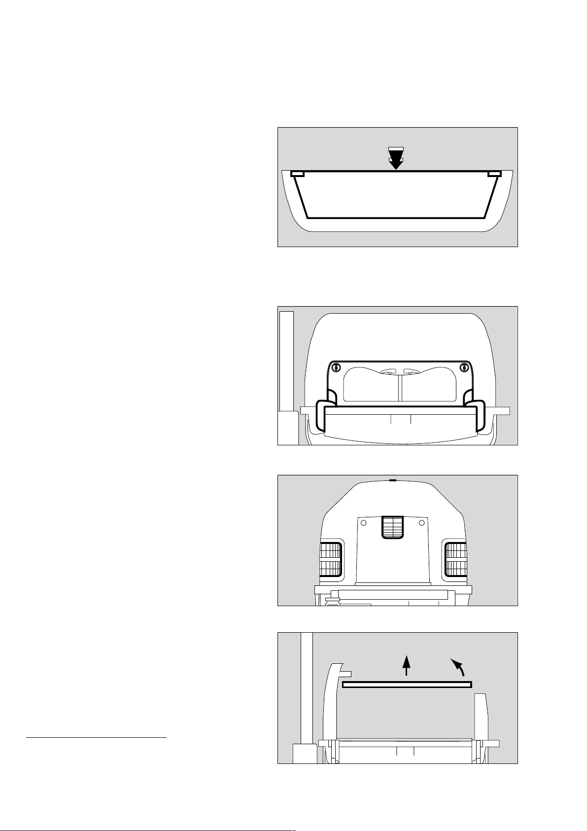
Disinfecting/Cleaning/Sterilising
Stripping down
To remove the double wall:
● Remove the canopy and lay it upside down (on a soft,
non-abrasive surface).
1 Squeeze the double wall inwards slightly, and
2 Release the oblong holes of the double wall from the
retaining lugs in the canopy.
● Pull the double wall out of the canopy.
● Remove visible soiling with a disposable cloth and
detergent.
● Wipe-disinfect the surfaces.
● After allowing the disinfectant time to take effect (see
manufacturer's specifications), wipe the surface with a
clean damp cloth and then rub dry.
Open the front flap:
3 Turn the two locking knobs inwards as far as they will go
and fold down the front flap.
2
2
1
14929515
● Fold out the adjustable double walls to clean them.
● Open the side flaps in the same way.
● Remove visible soiling with a disposable cloth and
detergent.
● Wipe-disinfect the surfaces.
● After allowing the disinfectant time to take effect (see
manufacturer's specifications), wipe the surface with a
clean damp cloth and then rub dry.
● Remove all through-hole grommets, sleeves and liners etc.
● Clean them at 93
o
C in the cleaning and disinfecting
machine*.
● Remove the mattress from the bed.
3
3
17929515
18129515
4 Remove the bed.
Take care not to damage the sensor unit.
● Remove visible soiling with a disposable cloth and
detergent.
● Wipe-disinfect the surfaces.
● After allowing the disinfectant time to take effect (see
manufacturer's specifications), wipe the surface with
a clean damp cloth and then rub dry.
* Observe national and international standards on
cleaning, disinfecting and sterilisation procedures
(e.g. EN 285, EN 554, EN 556).
88
4
4
11929515
Page 89

Remove the X-ray drawer:
● Using the recessed handle, pull out the X-ray drawer
as far as it will go.
1 Tilt the drawer upwards and pull it out of the unit.
● Remove visible soiling with a disposable cloth and
detergent.
● Wipe-disinfect the surfaces.
● After allowing the disinfectant time to take effect (see
manufacturer's specifications), wipe the surface with a
clean damp cloth and then rub dry.
Remove trough:
2 Press both catches inwards and pull the trough upwards.
Disinfecting/Cleaning/Sterilising
Stripping down
1
120 29 515
3 Lift out the trough.
4 Remove the fan impeller.
● Remove visible soiling with a disposable cloth and
detergent.
● Wipe-disinfect the surfaces.
● After allowing the disinfectant time to take effect (see
manufacturer's specifications), wipe the surface with a
clean damp cloth and then rub dry.
● Turn the trough over.
5 Lift the air guide plate to the side to disinfect and clean.
● Remove visible soiling with a disposable cloth and
detergent.
● Wipe-disinfect the surfaces.
● After allowing the disinfectant time to take effect (see
manufacturer's specifications), wipe the surface with a
clean damp cloth and then rub dry.
2
3
2
20329515
3
4
11429515
5
11529515
89
Page 90

Disinfecting/Cleaning/Sterilising
Stripping down
Base frame/body
● Remove visible soiling with a disposable cloth and
detergent.
● Wipe-disinfect the surfaces.
● After allowing the disinfectant time to take effect (see
manufacturer's specifications), wipe the surface with a
clean damp cloth and then rub dry.
● Remove any impurities near the slits of the sensor unit.
Do not allow any moisture to enter the sensor.
Do not disinfect the sensor unit by immersion or spraying.
Control panel
● Pull off the turn-and-press rotary knob.
● Remove visible soiling with a disposable cloth and
detergent.
● Wipe-disinfect the surfaces.
● After allowing the disinfectant time to take effect (see
manufacturer's specifications), wipe the surface with a
clean damp cloth and then rub dry.
Do not allow any moisture to enter the control panel.
Do not disinfect the control panel by immersion or
spraying.
Use only the recommended cleaning agents and disinfectants.
Otherwise, there is a risk of cracks forming in the transparent
parts, e.g. due to the use of alcohol.
Do not use UV radiation on the incubator, because this
treatment may cause cracks in the transparent components.
1832951519529515
D
90
Page 91

Before reusing for a patient
● Check that the system has been cleaned and disinfected in
conformity with the regulations of the hospital.
● Reassemble the equipment with disinfected hands.
● Refit all equipment – see "Stripping down", page 86.
When inserting the trough, make sure that both holders
click into place.
If the holders of the trough are damaged:
● Call DrägerService.
Fitting the water connection pipe:
1 Check the O-ring (2M 50 346) for damage and replace
if necessary.
2 Check the locking valve for damage.
Disinfecting/Cleaning/Sterilising
Before reusing for a patient
1
2
To make the water connection pipe easier to install, tilt the
incubator.
● Connect the incubator to the mains power supply.
● Switch on the incubator = press the on/off switch until it
clicks into position (see page 37).
● Tilt the bed (see page 23).
3 Push the water connection pipe into the guide duct, holding
the LuerLock connection vertically at the top.
● After overcoming a spring force,
4 Turn the water connection pipe counter-clockwise 90o and
secure the locking valve in the holder.
19829515
3
25429515
4
91
19929515
Page 92

Disinfecting/Cleaning/Sterilising
Before reusing for a patient
● Check that the incubator is ready for operation –
see "Before each use" on page 26.
To remove possible disinfectant residue, we recommend
running the incubator in standby mode.
● Switch on Caleo
● Activate air temperature control (see page 38).
● Run Caleo
®
(see page 37).
®
at 37 oC with opened flaps.
If using a water container:
Do not refill the water container until just before placing the
patient in the incubator (see page 24)!
If using a water bag:
Do not connect the water bag until just before placing the
patient in the incubator (see page 24)!
92
Page 93

Disinfecting/Cleaning/Sterilising
Care list
What How often How
Disinfect and clean Sterilise
Reusable components Care intervals
Connection tube Replace weekly and with each
change of patient
Water container Change of patient/weekly yes yes
Water connection pipe Change of patient/weekly yes yes
Canopy Change of patient/weekly yes
Double wall Change of patient/weekly yes
Front flap Change of patient/weekly yes
Side flap Change of patient/weekly yes
Double walls Change of patient/weekly yes
Through-hole sleeves etc. Change of patient/weekly yes
Mattress Change of patient/weekly yes
X-ray drawer Change of patient/weekly yes
Trough Change of patient/weekly yes
Fan bar Change of patient/weekly yes
Fan impeller Change of patient/weekly yes
Base frame Change of patient/weekly yes
Control panel Change of patient/weekly yes
Rotary knob (control panel) Change of patient/weekly yes
Fresh air filter Replace every 2 months
Wipe
a
Cleaning and
disinfecting
machine
93 oC
b
c
Steam 134
Care list
oCc
a. Use surface disinfectants based on aldehydes and quaternary ammonium compounds.
b. Use only detergent. Do not use disinfectants that release alkali or chlorine. Risk of corrosion!
c. Observe national and international standards on cleaning, disinfecting and sterilisation procedures
(e.g. EN 285, EN 554, EN 556).
93
Page 94

Maintenance intervals
Maintenance intervals
Disinfect and clean the incubator or the relevant parts before each maintenance operation, even when returning the
equipment for repair purposes.
Disconnect from the mains before each maintenance operation. Risk of electric shock.
Intervals Who?
when
necessary
weekly every
2 months
every
6 months
once
a year
every
two years
Replaceable parts:
Medical
Fresh air filter X
and technical
personnel
Medical
and technical
Grommets, sleeves etc. X
a
personnel
O-ring, for water
connection pipe X
Medical
and technical
personnel
b
Fan motor X
Authorised
technicians
Lithium battery X Authorised
technicians
Skin temperature
c
X
Medical personnel
sensors
Adhesive pads X
d
Medical personnel
Foam mattress X Medical personnel
Maintenance:
Device servicing and
maintenance
X Authorised
technicians
Calibration:
2 sensors X Authorised
O
technicians
a. Replace if the material becomes brittle or sticky or if strips of material have become detached
b. Replace after 18000 – 20000 operating hours
c. At the latest when changing patient
d. At the latest when changing patient
94
Page 95

Disposal
Disposal of the connection tube and fresh air filter
— with household waste.
Disposal of O2 sensors and battery
— Do not throw into the fire. Risk of explosion.
— Do not force open: risk of chemical burns.
— Do not recharge the battery.
Special waste:
— Dispose of special waste in accordance with national waste
disposal regulations.
Further information can be obtained from national and local
environmental and legislative authorities and suitable waste
disposal companies.
Maintenance intervals
Disposal
Disposal of incubator
At the end of its useful life.
— Dispose of the incubator in conformity with national waste
disposal regulations.
or
— Hand the incubator over to a suitable waste disposal
company for disposal.
Further information can be obtained from national and local
environmental and legislative authorities.
All plastic components weighing more than 50 g must be
marked with their material code in order to ensure
environmentally sound disposal.
95
Page 96

96
Page 97

Troubleshooting – Error Messages
Troubleshooting – Error Messages
Contents
Troubleshooting – Error Messages . . . . . . . . . . . . . . . . . . . . . . . . . . . . . . . . . . . . . . . 98
Troubleshooting – Faults . . . . . . . . . . . . . . . . . . . . . . . . . . . . . . . . . . . . . . . . . . . . . . . 102
97
Page 98

Troubleshooting – Error Messages
Troubleshooting – Error Messages
All error messages are displayed on the screen. They are listed in the table below in alphabetical order.
See also "Alarm description" on page 121.
Message Cause Remedy Duration
audible
alarm muted
Air heater inoperable
Measured value flashes on the screen.
Red alarm LED on the control panel
flashes.
Central alarm indicator lights up.*
Intermittent audible alarm is sounded (5x).
Air temp. deviation above 1.5
(see "Configuration" on page 71. )
Measured value flashes on screen.
Yellow alarm LED on the control panel
flashes.
Central alarm indicator lights up.*
Intermittent audible alarm is sounded (3x).
Air temp. sensor inoperable
Red alarm LED on the control panel
flashes.
Central alarm indicator lights up.*
Intermittent audible alarm is sounded (5x).
Air temperature too high
Measured value flashes on screen.
Red alarm LED on the control panel
flashes.
Central alarm indicator lights up.*
Intermittent audible alarm is sounded (5x).
Battery discharged
Yellow alarm LED on the control panel
flashes.
Connect skin 1 sensor
Three dashes flash on screen in place of
the measured value.
Red alarm LED on the control panel
flashes.
Central alarm indicator lights up.*
Intermittent audible alarm is sounded (5x).
Fan inoperable
Red alarm LED on the control panel
flashes.
Central alarm indicator lights up.*
Intermittent audible alarm is sounded (5x).
Heater temp. sensor inoperable
Red alarm LED on the control panel
flashes.
Central alarm indicator lights up.*
Intermittent audible alarm is sounded (5x).
* The central alarm light can be switched off. See "Setting system parameters" on page 73.
o
C
Air heater defective. Call DrägerService. 1 min.
The specified tolerance limit
for deviation from the set value
has been exceeded by a value
either above the maximum or
below the minimum value
Air temperature sensors are
defective.
Incubator temperature above
38 oC.
Incubator temperature above
40 oC.
Flat battery. Connect the incubator to the
Probe for skin temperature
(yellow) is not connected.
Fan defective. Check fan impeller.
Air heater temperature
sensors defective.
Reduce/increase humidity.
Close canopy, front flap and
hand ports.
Check the set value and the
configuration (page 71).
Call DrägerService. 1 min.
Remove external temperature
sources.
Call DrägerService.
power supply for about 30
minutes
Check connection and
correct if necessary.
Call DrägerService.
Call DrägerService. 1 min.
15 min.
5 min.
1 min.
5 min.
5 min.
98
Page 99

Troubleshooting – Error Messages
Message Cause Remedy Duration
audible
alarm muted
Humidifier inoperable
Measured value (closed-loop humidity
Water heater is defective. Switch off humidity module.
Call DrägerService.
1 min.
control) or set value (open-loop humidity
control) flashes on the screen.
Red alarm LED on the control panel
flashes.
Central alarm indicator lights up.*
Intermittent audible alarm is sounded (5x).
Humidity deviation above 10 %
Yellow LED lights up on the control unit.
Canopy, front flap or hand
ports are open.
Sensor defective.
Close canopy, front flap or
hand ports.
Check water supply
15 min.
connection.
Call DrägerService.
Humidity sensor inoperable
Measured value on screen flashes.
Humidity sensor is defective Switch off humidity control.
Call DrägerService.
1 min.
Red alarm LED on the control panel
flashes.
Central alarm indicator lights up.*
Intermittent audible alarm is sounded (5x).
Key pad locked
Intermittent audible alarm is sounded (3x)
when a button is pressed.
Oxygen concentration below 18 % O2 concentration less than
Button functions (set value
input/weighing/ menu button)
disabled
18 Vol.%
Activate push button
functions (page 77).
Check that the correct gas is
connected.
-
1 min.
Call DrägerService.
Oxygen deviation above 5 %
(can be set between 3 and 5 % – see
"Configuration" on page 71.)
Measured value flashes on screen.
Red alarm LED on the control panel
flashes.
Central alarm indicator lights up.*
Intermittent audible alarm is sounded (5x).
Difference in measured O2
concentration is greater than
3 or 5%.
Close the canopy, front flap
and hand ports.
Check O2 connection.
Check O2 supply via central
medical gas pipeline or O2
cylinder.
Check configuration
(page 71).
2 min.
Call DrägerService.
Oxygen module inoperable
Display flashes on screen.
Controller of O2 module is
defective
Switch off oxygen module.
Call DrägerService
1 min.
Red alarm LED on the control panel
flashes.
Central alarm indicator lights up.*
Intermittent audible alarm is sounded (5x).
Oxygen sensor deviation above 3 %
Measured value flashes on screen.
Sensor 1 or sensor 2 is
defective.
Switch off oxygen module.
Call DrägerService
1 min.
Red alarm LED on the control panel
flashes.
Central alarm indicator lights up.*
Intermittent audible alarm is sounded (5x).
* The central alarm light can be switched off. See "Setting system parameters" on page 73.
99
Page 100

Troubleshooting – Error Messages
Message Cause Remedy Duration
audible
alarm muted
Oxygen sensor 1 inoperable
Measured value flashes on screen.
Red alarm LED on the control panel
Sensor for oxygen
measurement is defective.
Sensor 1 is defective.
Switch off oxygen module.
Call DrägerService
1 min.
flashes.
Central alarm indicator lights up.*
Intermittent audible alarm is sounded (5x)
Oxygen sensor 2 inoperable
Measured value flashes on screen.
Red alarm LED on the control panel
Sensor for oxygen
measurement is defective.
Sensor 2 is defective.
Switch off oxygen module.
Call DrägerService
1 min.
flashes.
Central alarm indicator lights up.*
Intermittent audible alarm is sounded (5x)
Skin 1 less than 0.5 oC above skin 2
(see "Configuration" on page 71.)
The measured values for skin
temperatures flash on-screen.
Yellow alarm LED on the control panel
Kangaroo mode alarm:
temperature difference
between the skin temperature
(yellow) and peripheral
temperature (white) too low
Check patient's heat
exchange.
Check configuration
(page 71).
15 min.
flashes.
Central alarm indicator lights up.*
Intermittent audible alarm is sounded (3x).
Skin 1 more than 4.0 oC above skin 2
(see "Configuration" on page 71.)
The measured values for skin
temperatures flash on-screen.
Yellow alarm LED on the control panel
Kangaroo mode alarm:
temperature difference
between the skin temperature
(yellow) and peripheral
temperature (white) too high
Check patient's heat
exchange.
Check configuration
(page 71).
15 min.
flashes.
Central alarm indicator lights up.*
Intermittent audible alarm is sounded (3x).
Skin 1 sensor fault
Measured value flashes on screen.
Sensor for core temperature
is defective.
Replace sensor 5 min.
Red alarm LED on the control panel
flashes.
Central alarm indicator lights up.*
Intermittent audible alarm is sounded (5x).
Skin 1 temp. deviation above 0.5
(can be set between 0.3 and 1.0 oC –
see "Configuration" on page 71.)
Measured value flashes on screen.
Yellow alarm LED on the control panel
flashes.
Central alarm indicator lights up.*
Intermittent audible alarm is sounded (3x).
The specified limit value for
deviation from the set value
has been exceeded.
Check that the sensor is
correctly attached to the
patient.
Close the canopy, front flap
or hand ports.
Switch off external heat
sources.
Remove double walls.
5 min.
o
C
Change configuration
(page 71).
o
Skin 1 temperature above 39
C
Measured value on screen flashes.
Red alarm LED on the control panel
flashes.
Central alarm indicator lights up.*
Intermittent audible alarm is sounded (5x).
Peripheral temperature too
high.
Check that sensor is
correctly attached to the
patient.
Switch off external heat
sources.
Check whether double walls
2 min.
can be removed.
* The central alarm light can be switched off. See "Setting system parameters" on page 73.
100
 Loading...