

Page 1

8. Repair Information Unit, Electronics Module, Climatic Sensor
Table of Contents
8.1Unit................................................................................................................................2
8.1.0Table of Contents...................................................................................................2
8.1.1Information on Unit 2M 20 276 / 2M 20 615 (of Inc. 8000 SC/IC/NC)....................3
8.1.2PCB Unit and Fuses...............................................................................................3
8.1.3Air Heating with Thermal Release..........................................................................6
8.1.4Boiler with Water heating and Thermostatic Switch...............................................6
8.1.5Fan Motor...............................................................................................................8
8.1.6 Mains Transformer...............................................................................................10
8.1.7Semiconductor Relay...........................................................................................10
8.1.8Test of Heating Unit (Complete)...........................................................................11
8.1.9Voltage Selection.................................................................................................26
8.1.10Replacement of Unit in the event of Repair..........................................................27
8.1.11Repair Information and Change Status................................................................27
8.2Electronics module......................................................................................................28
8.2.0Table of Contents.................................................................................................28
8.2.1Keyboards............................................................................................................30
8.2.2PCB Display Air Temperature..............................................................................36
8.2.3PCB Display (of options), PCB Display Skin (as of SW 11 and 21).....................39
8.2.4PCB Display Humidity (only Inc. 8000 SC/NC)....................................................42
8.2.5PCB CPU..............................................................................................................44
8.2.6PCB Analog with PCB Filter.................................................................................56
8.2.7PCB Power Pack..................................................................................................74
8.2.8PCB Motherboard and PCB Fan..........................................................................80
8.2.9PCB Switch...........................................................................................................84
8.2.10N/A.......................................................................................................................84
8.2.11PCB Controller (RS232) 82 90 581......................................................................85
8.3Climatic sensor............................................................................................................90
8.3.0Table of Contents.................................................................................................90
8.3.1Information on Climatic Sensors..........................................................................90
8.3.2Climatic Sensor 82 90 380 and 2M 21 688..........................................................91
8.3.3Testing and Adjustment........................................................................................92
8.3.4Replacement and Repair......................................................................................95
8.3.5Repair Information and Change Status................................................................96
6141.22x Incubator 8000 SC/IC/NC Repair Information 11.99 Page 1 of 96
Page 2
8.1 Unit
8.1.0 Table of Contents
8.1.3
H2O
Air
8.1.5
8.1.4
8.1.7
8.1.6
8.1.2
8.1.1 Information on Units Used
8.1.2 PCB Unit and Fuses
8.1.3 Air Heating with Thermal Release
8.1.4 Boiler with W ater Heating and Thermostatic Switch
8.1.5 Fan Motor
8.1.6 Mains Transformer
8.1.7 Semiconductor Relay
8.1.8 Testing of Unit (Complete)
8.1.9 Voltage Selection
8.1.10 Replacement of Unit in the event of Repair
8.1.11 Repair Information and Change Status
6141.22x Incubator 8000 SC/ IC/NC Repair Information 11.99 Page 2 of 96
Page 3
8.1.1 Information on Unit 2M 20 276 / 2M 20 615 (of Inc. 8000 SC/IC/NC)
Characteristics:
-
PCB Unit 82 90 511
- All connections to printed circuit board plugged-in
- Heating cartridges for one mains voltage only (100 V, 120 V / 127 V or 230 V / 240 V)
- Boiler (complete) plugged-in. In the Inc. 8000 SC/IC/NC it can be removed through a
service opening without dismounting the Unit
Since both Units are identical as far as their function is concerned it is possible to use the Unit
2M 20 615 in the Inc. 8000, refer to 8.1.9 "Replacing in the event of Repair".
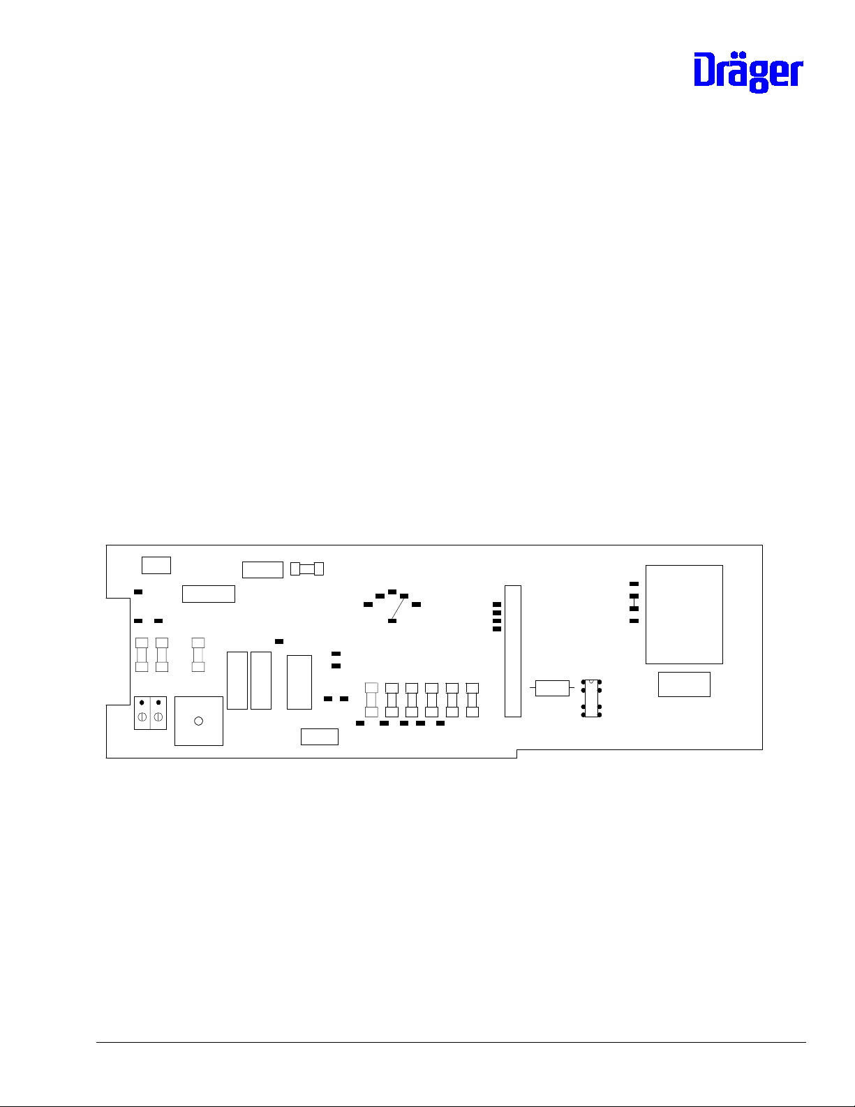
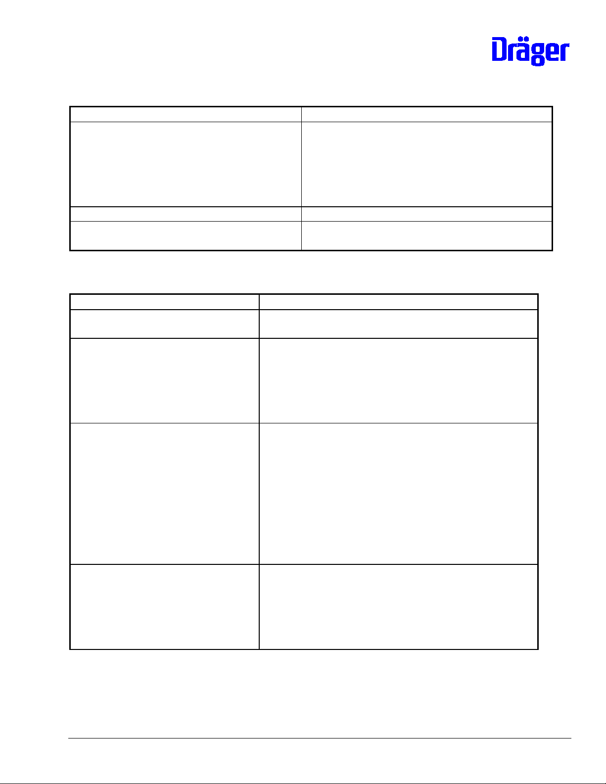
8.1.2 PCB Unit and Fuses
Layout Component Mounting Side:
T58
F4
T57
100
110
127
230
T60
240
T3
T4
T2
T5
X1
T41
T42
T43
T44
T54
T56
T59
F1 F2
X12
T61
X10
X11
F3
K4
K3
X3 X4
T53
K1
K5
K2
X2
F5 F6 F7 F8 F9 F10
T55
T1
T6
T7 T10 T9 T8 T63
C2 +
6141.22x Incubator 8000 SC/ IC/NC Repair Information 11.99 Page 3 of 96
Page 4
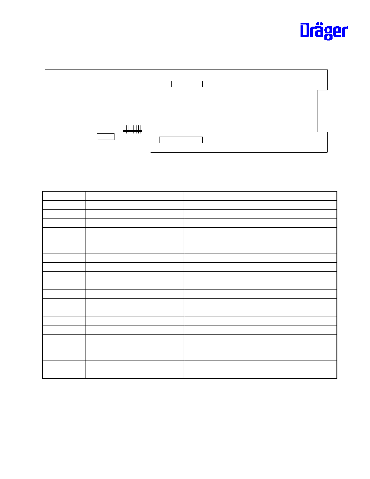
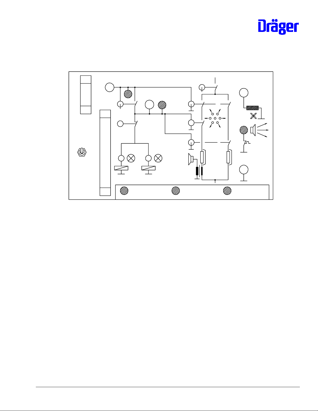
Layout Rear:
X7
X5
X13
X6
Component Mounting without Fuses:
Position Component Function
X1 Connector 18 13 641 Cable connection to electronics module
X2 Connector 18 13 544 Cable connection to valve(s)
X3, X4 Terminal 68 04 759 Mains connection
X5 Connector 18 10 669 Connection for coil of fan watchdog,
Thermostatic switch water shortage and
control of semiconductor relay
X6 Connector 18 28 592 Connection mains voltage for transformer
X7 Connector 18 28 576 Return transformer voltages
X10 Connector 18 28 533 Connection heating cartridge for water
heating
X11 Connector 18 28 541 Connection semiconductor relay supply side
X12 Connector 18 28 525 Connection heating cartridge of air heating
X13 Connector 18 28 533 Connection fan motor
K1, K5 Relay 18 30 732 Mains closing relay
K2 Relay 18 21 474 Safety relay for heating
K3 Relay 18 21 474 Safety relay for valve(s)
K4 Relay 83 01 198 Safety relay for disconnection Semiconductor
relay of heating valve(s)
T54 Transformer 18 13 927 Auxiliary transformer for mains closing relays
K1 and K5
6141.22x Incubator 8000 SC/ IC/NC Repair Information 11.99 Page 4 of 96
Page 5
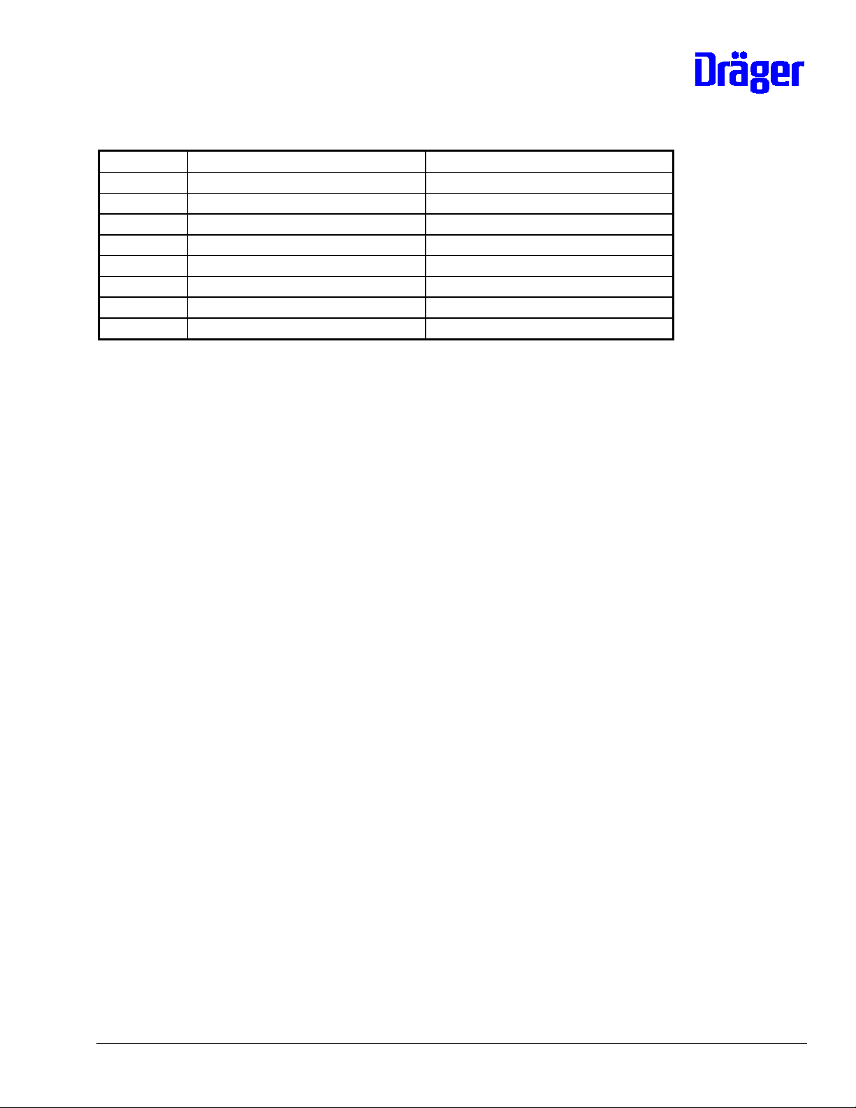
Fuses:
Position 100 V to 127 V 220 V to 240 V
F1, F2 T 6,3 A 18 15 172 T 3,15 A 18 15 148
F 3 T 80 mA 18 14 974 T 40 mA 18 14 931
F4 T 1A 18 15 083 T 500 mA 18 15 059
F5 T 200 mA 18 15 016 T 200 mA 18 15 016
F6 T 500 mA 18 15 059 T 500 mA 18 15 059
F7 T 2,5 A 18 15 121 T 2,5 A 18 15 121
F8 T 1,6 A 18 15 105 T 1,6 A 18 15 105
F9, F10 T 160 mA 18 15 008 T 160 mA 18 15 008
Testing:
Refer to 8.1.8 "Testing Unit (complete)"
Replacement in the event of repair:
In the event of repair the PCB Unit 82 90 511 (complete) can be replaced or
components can be renewed. All relays are available for this purpose, refer to
component mounting list.
6141.22x Incubator 8000 SC/ IC/NC Repair Information 11.99 Page 5 of 96
Page 6
8.1.3 Air Heating with Thermal Release
Three different heating cartridges are uses i n this Unit:
- 220 V to 240 V (132 Ohm) 2M 20 329
- 120 V / 127 V (33 Ohm) 2M 20 331
- 100 V (25 Ohm) 2M 20 669
Prolonged heating cartridges are in use since 1992. When installing these heating cartridges
lock them using an M4-screw.
M4
8.1.3.3 Thermostatic Switch
A safety thermostat which has been tripped must be replaced, no soldering permitted. Prior to
replacement, determine cause for tripping, for example:
- wrong heating cartridges
- device assembled incorrectly
The resistance of the thermostat can be checked at its contacts.
8.1.4 Boiler with Water heating and Thermostatic Switch
The boiler system is a plug-in unit consisting of:
- Aluminum housing 2M 20 291
- Heating cartridge for 230 V, 120 V / 127 V or 100 V
- Cap for vaporizer 2M 20 292
- O-ring cap 2M 08 777
6141.22x Incubator 8000 SC/ IC/NC Repair Information 11.99 Page 6 of 96
Page 7
- Thermostatic switch water shortage alarm 115 °C 2M 20 381
- Safety thermostat 140 °C 2M 20 382
- Plug-in connector
All components can be replaced in the event of repair. If the safety thermostat has been
tripped both thermostatic switches must be replaced.
Service:
The condition of the boiler housing must be checked every six months. If the vaporizer
chamber is soiled it can be scraped out.
Heating cartridges:
- 220 V to 240 V (530 Ohm)2M 20 327
- 120 V / 127 V (132 Ohm) 2M 20 328
- 100 V (100 Ohm) 2M 20 668
Prolonged heating cartridges are in use since 1992. As before, the end of the heating
cartridge must be flush with the boiler housing.
6141.22x Incubator 8000 SC/ IC/NC Repair Information 11.99 Page 7 of 96
Page 8
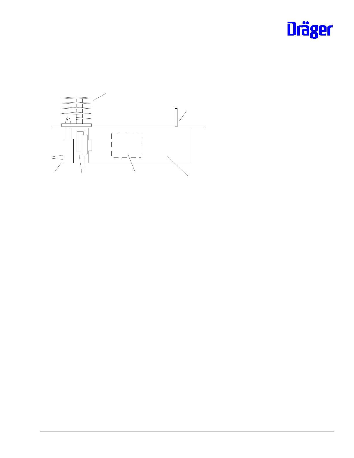
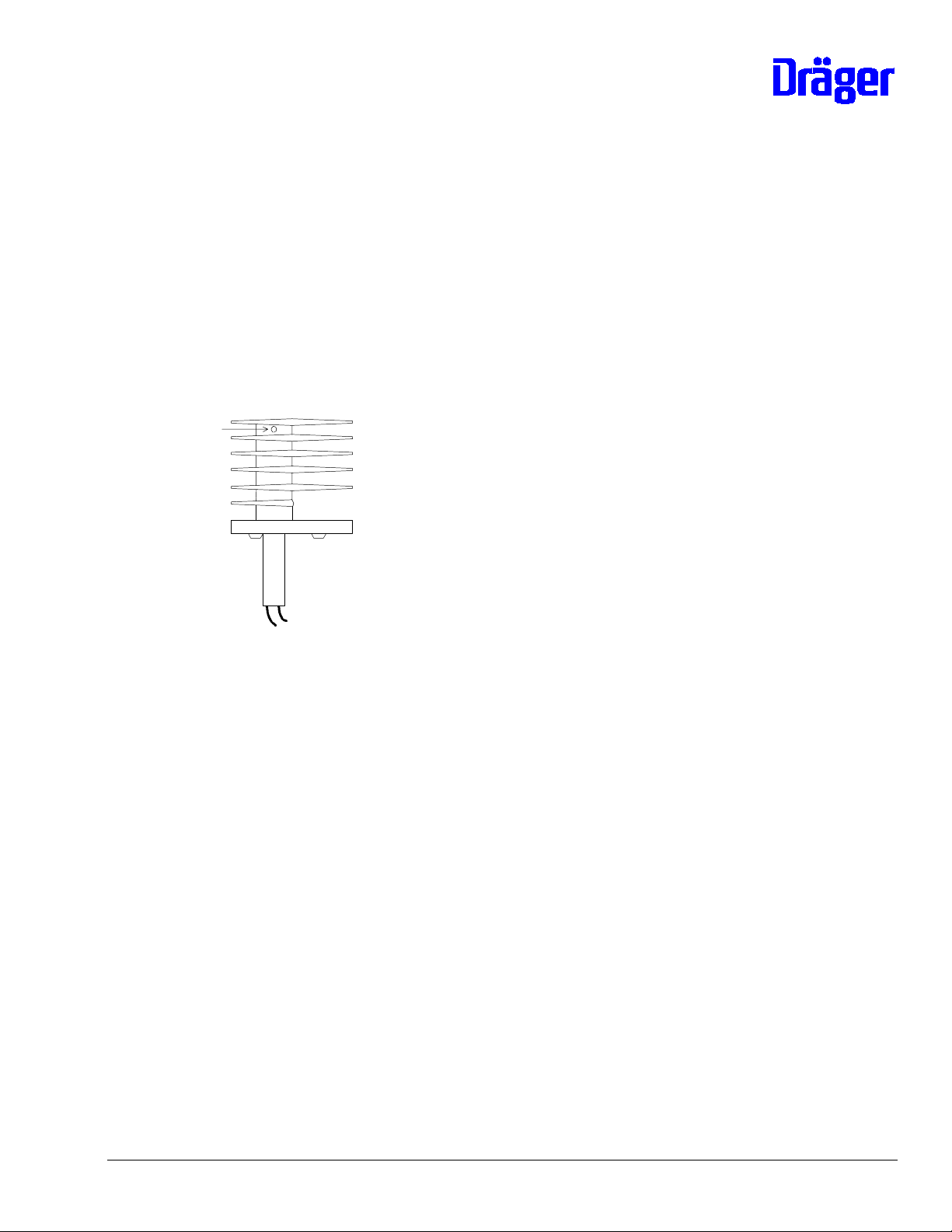
8.1.5 Fan Motor
Fan motor (simplifi ed representation):
A
43,5 +/- 0,5
D
Service required:
The fan motor must be lubricated every six months with oil 2M 07 839. Procedure:
Remove screw A located next to the motor shaft and apply approx. 10 drops of oil into
the bore hole.
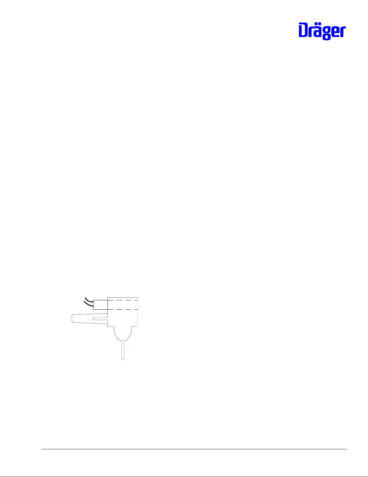
Bearing play:
C
E
B
The bearing play can be adjusted using screw B. The screw must be adjusted such to
allow a motor shaft play of approx. 0.2 mm. The screw must be sealed with locking
compound.
6141.22x Incubator 8000 SC/ IC/NC Repair Information 11.99 Page 8 of 96
Page 9

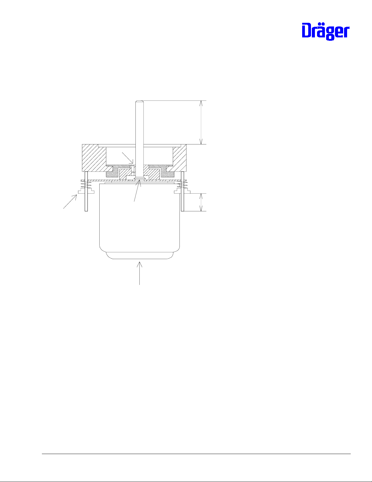
Replacing the Fan Motor
Procedure:
- Interrupt mains connection to Incubator and remove Unit
- Unscrew coil of the fan watchdog from aluminum block of the motor mount
- Disconnect cable connection from motor to printed circuit board
- Unscrew fixing bracket underneath the motor
- Measure and write down dimension E of the 4 retaining screws
- Remove 4 retaining screws
D
D
- Using oil 2M 07 839 lubricate later bearing surface of V-ring C of the new motor
- Plug new motor with springs onto threaded pins and screw 4 retaini ng screw D onto
dimension
E
- Precision adjustment:
While the Unit is in its working position the motor shaft must protrude by
43.5 +/- 0.5 mm from the top edge of the aluminum block and must be positioned
perpendicularly to the block. The motor must be suspended freely on the springs.
- Seal the 4 retaining screws D with Loctite 221.
- Lubricate the motor
- The remaining steps of the installation are performed in the reverse order
- When connecting the grounding rings make sure that they do not protrude from the
edge of the resilient motor retaining plate. The fl at head screws of the motor retaining
clip must be sealed with locking compound.
After installation into the Incubator make sure that the fan wheel does not rub against
-
the tank and that it can move freely on the spring-loaded bearing.
6141.22x Incubator 8000 SC/ IC/NC Repair Information 11.99 Page 9 of 96
Page 10

8.1.6 Mains Transformer
- Transformer with Efen sensor 82 90 426
The test procedure is described under 8.1.8.3
8.1.7 Semiconductor Relay
The test procedure is described under 8.1.8
The following spare parts can be used in the event of repair:
- Semiconductor relay (electromagnetic or crydom 18 31 399
partial interference suppression)
- Semiconductor relay 18 21 148
Note: The semiconductor relays 18 31 399 have a better switching behavior.
6141.22x Incubator 8000 SC/ IC/NC Repair Information 11.99 Page 10 of 96
Page 11

8.1.8 Test of Heating Unit (Complete).
8.1.8.0 Contents
8.1.8.1 Test equipment required
8.1.8.2 Preparation of test
8.1.8.3 Test of power-up relay and supply voltages
8.1.8.4 Test of fan monitoring
8.1.8.5 Test of relay K4
8.1.8.6 Test of relay K3
8.1.8.7 Test of relay K2, air heating and feedback air heating
8.1.8.8 Test of relay K2, water heating and thermo-switch
8.1.8.9 Test of heating unit inside incubator
8.1.8.1 Test equipment required
- Tester heating unit Inc. 8000 79 01 764
- Multimeter 79 01 021
- Measuring line, red 1 m 79 01 022
- Measuring line, black, 1m 79 01 023
- Mains line (only if heating unit is disassembled for test)
- 40-pole ribbon cable use the one of incubator or
"test board uni 40" 79 00 610
- 10-pole ribbon cable included in tester "heati ng unit"
Inc. 8000" 79 01 764 or use the one of
"test board uni 40" 79 00 610
6141.22x Incubator 8000 SC/ IC/NC Repair Information 11.99 Page 11 of 96
Page 12
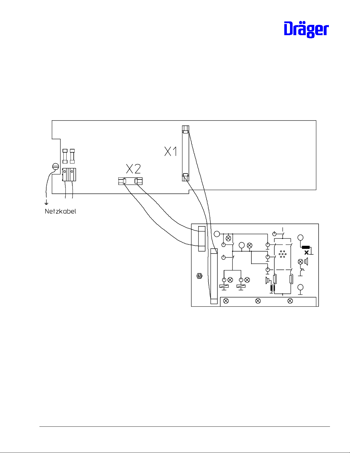
8.1.8.2 Preparation of test
The heating unit of Incubators 8000 SC/ICNC can be tested while assembled or
disassembled.
Note: If the unit is disassembled an isolating transformer must be used.
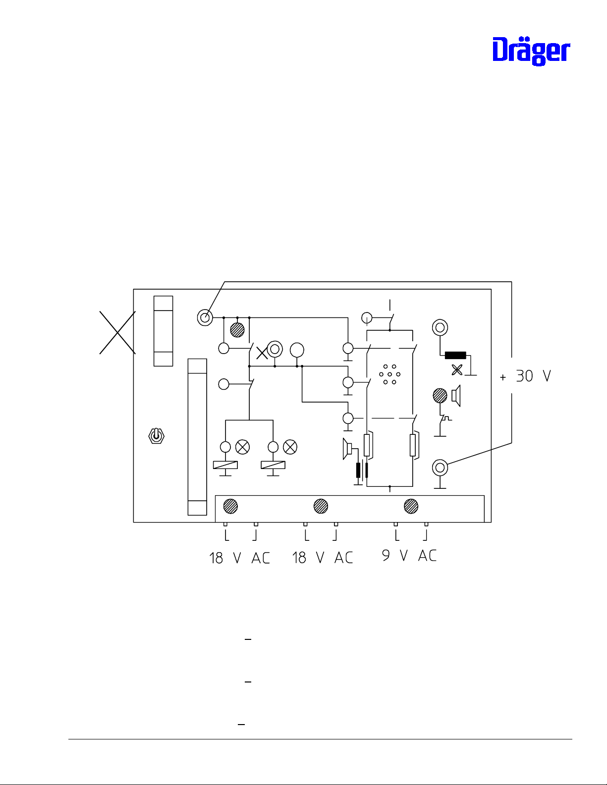
Test set-up (Netzkabel = power cord):
PCB Unit (part of the heating unit)
- Interrupt mains connection
- Connect tester to X1 PCB Unit using cable
- Connect tester to X2 PCB Unit, the cable connection to the valve(s) must be interrupted
before
- Set all switches at tester to "0" (off)
- Interrupt water supply to boiler of the heating unit
- Attach fan wheel
6141.22x Incubator 8000 SC/ IC/NC Repair Information 11.99 Page 12 of 96
Page 13

- Establish mains connection to incubator (heating unit installed) respective to heating
unit (not installed)
Set switch K1 at tester to "1" (on).
- Action inside the heating unit
o Mains power-up relays K1/K5 (heating unit 82 90 511) on
o Fan wheel turns
- Test of tester displays:
o LED + 30 V lights up
o LED 18 V ∼ F5 lights up
o LED 18 V ∼ F6 lights up
o LED 9 V ∼ F7 lights up
6141.22x Incubator 8000 SC/ IC/NC Repair Information 11.99 Page 13 of 96
Page 14
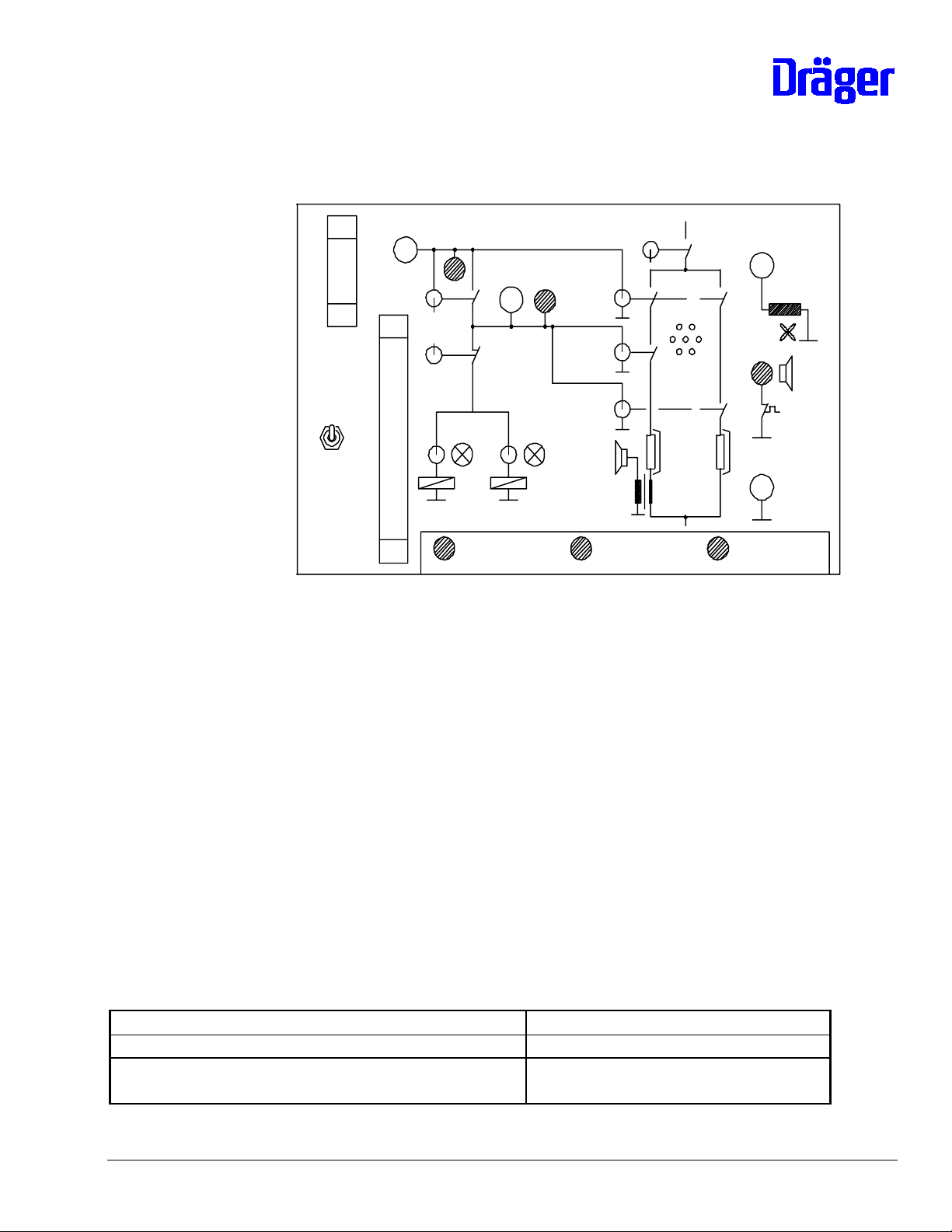
8.1.8.3 Test Set-up for testing a Unit in the Field
It is possible to use the fol lowing test-up for testing the power unit in the field:
open up the unit
•
disconnect the electronic module
•
connect the power unit and the test box with the 40 pin cable
•
carry out the test procedures as given in the following pages (i.e. item 8.1.8.3 and
•
onwards)
Note: The 3 LEDs marked in the drawing below are not active in this test-setup.
Do not connect
40 pin conn.
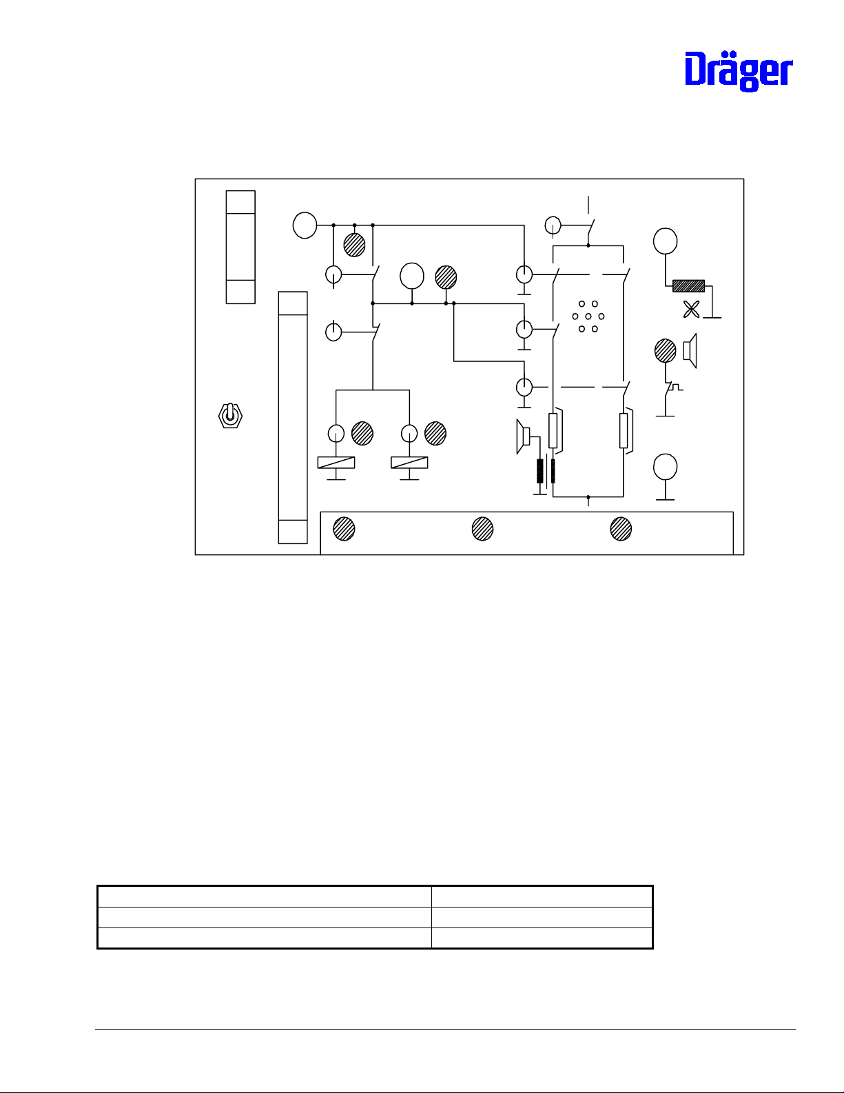
- Measurement of supply voltages at tester
o alternating voltage 18 V ∼ F5
test value: U= 18 V + 15 %
o alternating voltage 18 V ∼ F6
test value U = 18 V + 15 %
o alternating voltage 9 V ∼ F7
test value U = 9 V + 15 %
6141.22x Incubator 8000 SC/ IC/NC Repair Information 11.99 Page 14 of 96
Page 15
o direct voltage + 30 V
test value U = 30 V + 4 V
Possible errors:
Error Possible cause
no reaction after switching of K1 - mains input fuses F1/F2 defective
- fuse F3, F9 or F10 of auxiliary mains
transformer defective (F9 and F10 only on
PCB 82 90 511)
- mains power-up relay K1 or. K1/K5
defective
- fuse F4 for mains transformer
defective
- mains auxiliary transformer or rectifier
behind mains auxiliary transformer on PCB
defective
- Efen sensor of transformer defective
LED 18 V ∼ F5 off or voltage
outside the tolerance
- fuse F5 defective
- transformer defective
- voltage changeover to PCB O.K.?
LED 18 V ∼ F6 off or voltage
outside the tolerance
- fuse F6 defective
- transformer defective
- voltage changeover to PCB O.K.?
LED 9 V ∼ F7 off or voltage
outside the tolerance
- fuse F7 defective
- transformer defective
- voltage changeover to PCB O.K.?
LED + 30 V off, fan wheel stops - fuse F8 defective
- transformer defective
LED + 30 V off, fan wheel turns - rectifier for + 30 V on PCB defective,
alternating voltage exists, because fan wheel
turns
LED + 30 V lights up, fan wheel
stops
- fan motor defective
- starting capacitor for fan motor defective
6141.22x Incubator 8000 SC/ IC/NC Repair Information 11.99 Page 15 of 96
Page 16
Troubleshooting:
component to be tested test
fuses resistance measurement with disassembled fuses
mains auxiliary transformer and
rectifier behind mains auxiliary
transformer
Efen sensor transformer If after switch on the voltage on the PCB exists in
voltage measurement on the PCB via capacitor C2,
test value approx. 12 V
front of the transformer, and no LED lights up on the
tester, the transformer must be replaced. The voltage
(mains voltage) is measured on the PCB between the
soldering joint for mains voltage adjustment and fuse
F4.
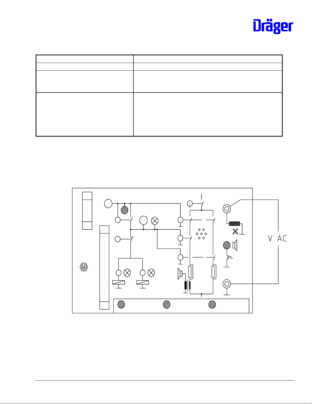
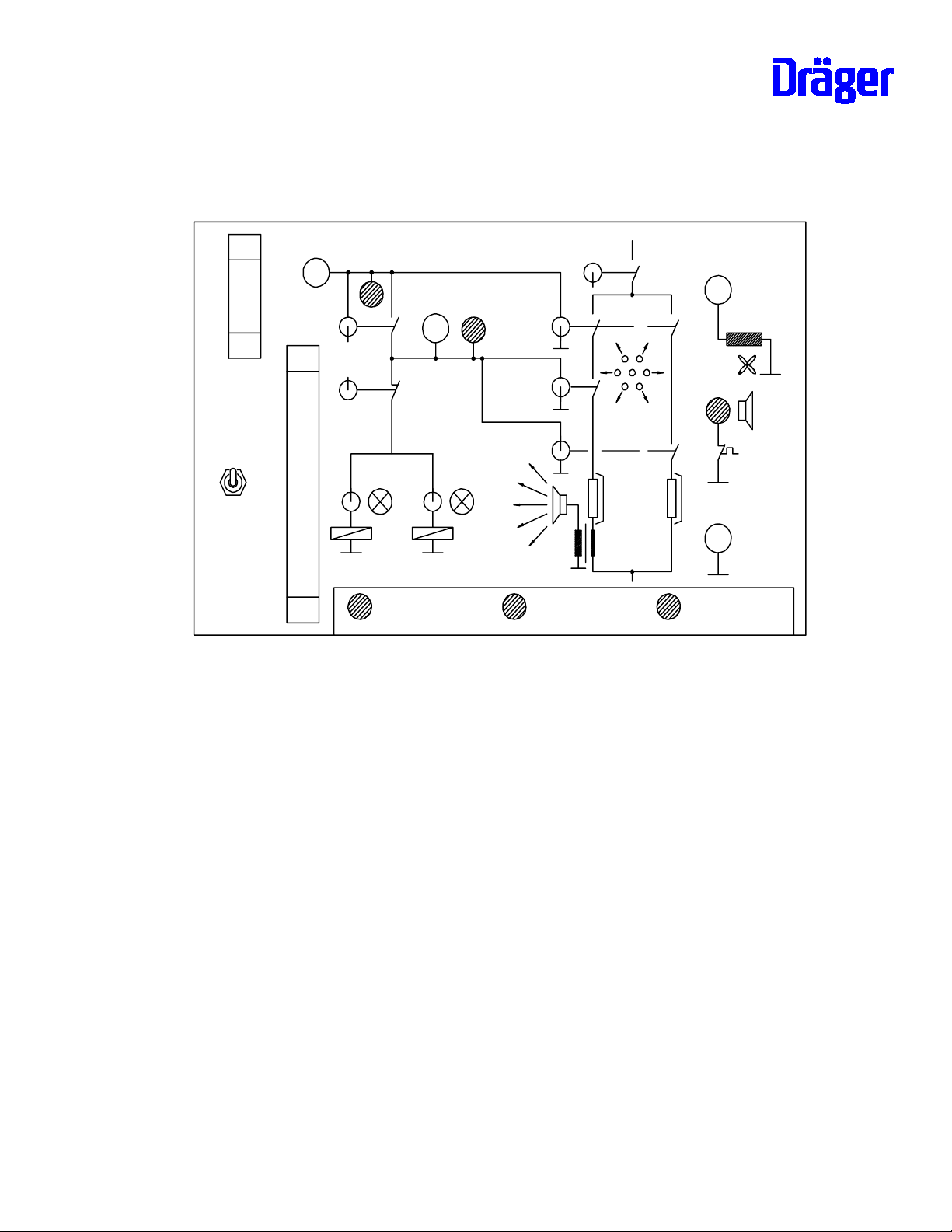
8.1.8.4 Test of fan monitoring
Prepare test as described in 8.1.8.2, test 8.1.8.3 passed.
Switch K1 at tester set to "1" (on), the fan wheel turns.
Measurement of alternating voltage at tester at socket "feedback fan" and GND.
Test value:
Measurement using an oscilloscope VSS > 2,8 V Peak to Peak
6141.22x Incubator 8000 SC/ IC/NC Repair Information 11.99 Page 16 of 96
Page 17
in this respect only the negative half-wave is important
or (very inaccurate)
Measurement using multimeter: V > 0,6 V
∼
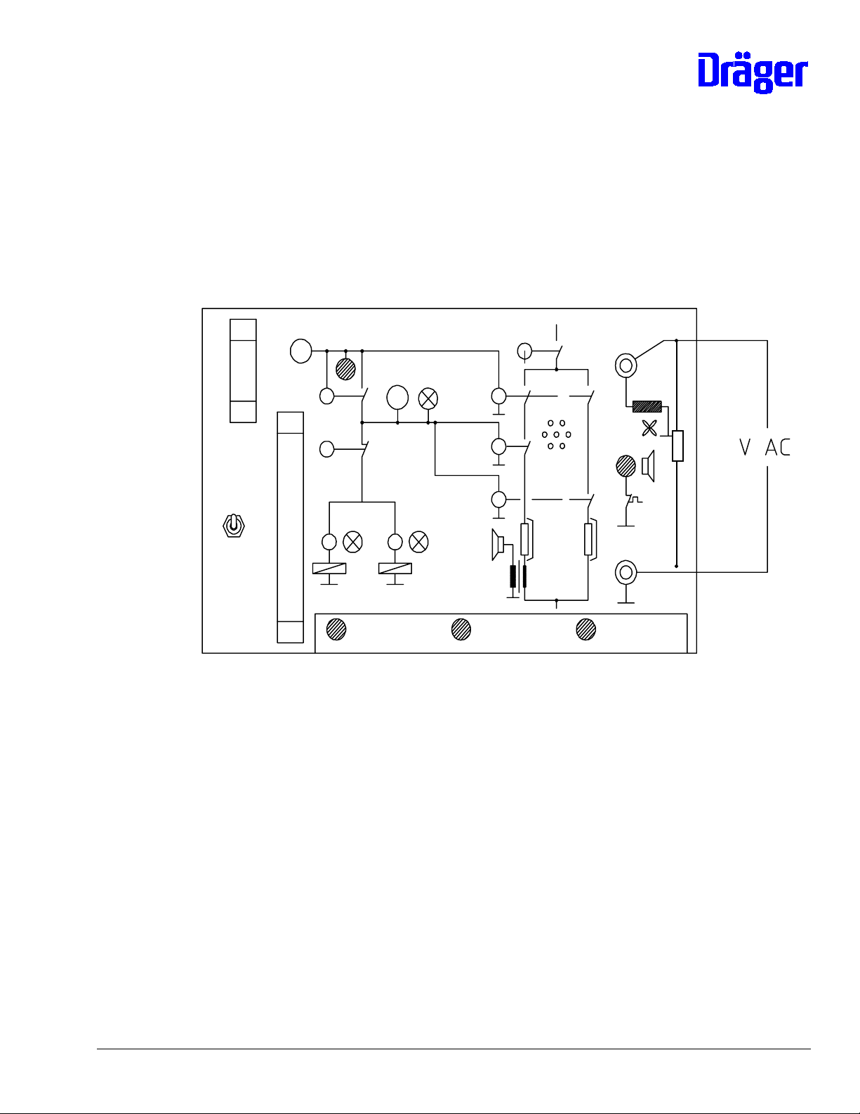
In the case where a high ohm multimeter is used, measure over a 10-20 KOhm resistor as
follows:
10-20 K
Note: Observe service information No. 29 in case of
electronics module Incubator 8000 with PCB Motherboard 82 00 850,
otherwise an excess output voltage might result in INOP error 9.
6141.22x Incubator 8000 SC/ IC/NC Repair Information 11.99 Page 17 of 96
Page 18
Possible errors:
Error possible cause
Voltage cannot be measured - fan wheel properly attached?
- cable connection of PCB to coil of fan
monitoring interrupted
fan monitoring interrupted
- coil of fan monitoring defective
(measure voltage directly at the coil
with the heating unit disassembled)
voltage too low observe service information No. 1 (Inc.
8000SC/IC) and service information No. 31 (Inc.
8000), with Inc. 8000 observe service
information No. 29!
voltage ok, but continuous fan
PCB Motherboard in electronics module
failure alarm at the assembled
incubator
INOP-error 9 with assembled
Incubator 8000
voltage too high, observe service i nformation
No. 29 for Incubator 8000. In Incubator 8000
SC/IC this means there is a failure on the PCB
Motherboard.
6141.22x Incubator 8000 SC/ IC/NC Repair Information 11.99 Page 18 of 96
Page 19
8.1.8.5 Test of relay K4
Prepare test as described in 8.1.8.2, test 8.1.8.3 passed.
Switch K1 at tester set to "1" (on), LED "+ 30 V" at tester lights up.
Test:
LED at tester behind switch K4 off
Switch K4 at tester set to "1" (on)
Test:
LED at tester behind switch K4 lights up
Switch K4 at tester set to "0" (off)
Note: The voltage behind the switching contacts of relay K4 can be
measured at the socket behind switch K4 at the tester.
Possible errors:
Error possible cause
LED always off or no voltage relay K4 defective
LED continuously lights up or vol tage exists
continuously
relay K4 defective
6141.22x Incubator 8000 SC/ IC/NC Repair Information 11.99 Page 19 of 96
Page 20
8.1.8.6 Test of relay K3
Prepare test as described in 8.1.8.2, tests 8.1.8.3 and 8.1.8.5 passed.
Switch K1 and K4 at tester set to "1" (on), LED "+ 30 V" lights up.
Switch V1 and V2 set to "1" (on)
Test: LED V1 and V2 at tester light up.
Switch K3 at tester set to "1" (on)
Test: LED V1 and V2 off
Switch K3 at tester set to "0" (off)
Possible errors:
Error possible cause
LED V1 or V2 continuously light up relay K3 defective
LED V1 or V2 continuously off relay K3 defective
6141.22x Incubator 8000 SC/ IC/NC Repair Information 11.99 Page 20 of 96
Page 21
8.1.8.7 Test of relay K2, air heating and feedback air heating
Prepare test as described under 8.1.8.2, tests 8.1.8.3 and 8.1.8.5 passed.
Switch K1 and K4 at tester set to "1" (on)
Switch K2 and HLR1 at tester set to "1" (on)
Test:
Horn (high frequency) in tester on, air heating gets warm (do not allow to become too
hot, at 350 °C the thermostatic switch operates)
Switch K2 set to "0" (off), the relay interrupts the power supply to the air heating
Test: Horn in tester off
Switch K2 set to "1" (on)
Test: Horn in tester on
Switch HLR1 set to "0" (off), the semiconductor relay of the ai r heating is switched off
Test: Horn in tester off
6141.22x Incubator 8000 SC/ IC/NC Repair Information 11.99 Page 21 of 96
Page 22
Possible errors:
Error possible cause
horn continuously off - relay K2 defective
- HLR1 of air heating defective
- air heating defective (hi ghly ohmic)
- thermostatic switch of air heating operates
- feedback defective
(line interrupt)
horn cannot be switched off with K2 relay K2 defective
horn cannot be switched off with HLR1 semiconductor relay HLR1of air heating
defective
Troubleshooting:
Component to be tested Test
Thermostatic switch air heating Resistance measurement approx. 0 Ohm, defective
switches must be replaced
Air heating Resistance measurement, different types of
heating cartridges may be used:
- 132 Ohm (230 V / 240 V)
- 33 Ohm (120V / 127 V)
- 25 Ohm (100V)
- 2 x 60 Ohm (230/115 V)
Semiconductor relay HLR1 for air
heating
For this bridge contacts of relay K2 on the PCB via
the test points:
- PCB 82 90 511 and PCB 82 00 600 ≥ 4:
bridge test points T55 and T57
- PCB 82 00 600 - 3:
bridge between fuse holder F2 and
solder tag T6 (connection air heati ng)
Switch on heating via tester (as described in the
test above); however, heating cannot be switched
off via K2.
Relay K2 For this bridge HLR1 of air heating at the mains
side directly at HLR at connections 1 and 2. The
front relay is the HLR for the air heating.
Switch on heating via tester (as described in the
test above), however, the heating cannot be
switched off via K2
6141.22x Incubator 8000 SC/ IC/NC Repair Information 11.99 Page 22 of 96
Page 23
8.1.8.8 Test of relay K2, water heating and thermostatic switch
Prepare test as described under 8.1.8.2, tests 8.1.8.3 and 8.1.8.5 passed.
Switch K1 and K4 at tester set to "1" (on)
Test: LED "H2O-shortage" shows green light
Switch K2 and HLR2 set to "1" (on)
Test: Boiler gets warm, after approx. 5 to 15 minutes horn on and LED "H2O-shortage" shows
red light
Switch HLR2 at tester set to "0" (off)
Test: After 5 minutes max. horn off, LED "H2O-shortage" at tester shows green light again
Repeat all test steps
6141.22x Incubator 8000 SC/ IC/NC Repair Information 11.99 Page 23 of 96
Page 24
Possible errors:
Error possible cause
Boiler does not heat up, LED "H2Oshortage" continuously shows green
light
- excess temperature switch at heating
switched off
- heating cartridge defective (hi ghly ohmic)
- relay K2 defective
- HLR2 of water heating defective
Boiler heats up, LED "H2O-shortage"
continuously shows green light
LED "H2O-shortage" continuously shows
red light
Boiler cannot be switched off by means
thermostatic switch water shortage defective
(always closed)
thermostatic switch water shortage defective
(always open)
HLR2 defective
of switch "HLR2"
Troubleshooting:
component to be tested test
excess temperature switch resistance test at resettable thermostatic switch
at boiler (approx. 0 Ohm).
If switch has operated both thermostatic
switches at the boiler must be replaced.
Semiconductor relay HLR2 of water
heating
For this, bridge contacts of relay K2 on the PCB
via the test points:
- PCB 82 90 511 and PCB 82 00 600 ≥ 4:
Bridge test points T55 and T58
- PCB 82 00 600 -3:
bridge between fuse holder F2 and
solder tag T11 (connection water heating)
Switch on heating via tester (as described in the
test above), however the heating cannot be
switched off via K2
Relay K2 For this, bridge HLR2 on the mains side directly
at HLR at connection 1 and 2. The HLR of the
water heating is the back relay. It must be
possible to switch on the heating via the tester,
however, it cannot be switched off by means of
switch "HLR2", but only with switch K2.
6141.22x Incubator 8000 SC/ IC/NC Repair Information 11.99 Page 24 of 96
Page 25

8.1.8.9 Test of heating unit in the incubator
Assemble incubator in operable condition and switch it on.
Test: No INOP or error alarm after switch-on test
Perform O2 calibration (not Inc. 8000 SC/NC) and increase O2-desired value by at least 5 %
by vol. compared to actual value
Test: No error-alarm in O2-module
Set humidity desired value to maximum:
Test with water supply:
The humidity measured value rises after a few minutes
Test without water supply:
Water-shortage alarm after a few minutes. The heating is switched off by the control,
the boiler cools down and the warning is switched off.
Repeat test several times.
Measurement of power consumption of water heating
Measure power consumption of unit. After self-test briefly withdraw and insert the
environmental sensor, thus air heating is suppressed for 90 seconds and with switched-
on humidity module and at max. desired value now a pulsating current of approx. 0,5 A
(230 V to 240 V-units) or of approx. 1 A (100 V to 127 V-units) can be measured.
Note: By pressing the two desired value buttons in the humidity module switched on for
approx. 3 seconds, a "heating LED" can be called up in the humidity module. Thus the
control and the pulsating current can be compared.
6141.22x Incubator 8000 SC/ IC/NC Repair Information 11.99 Page 25 of 96
Page 26

8.1.8.10 Testing of valves
As a special function the valve of Inc. 8000 IC can be triggered with the tester "heating unit
Inc. 8000".
Prepare test set up as described in 8.1.8.2, but connect valve(s) to X2 on the PCB Unit, the
previous cable connection to the tester is no longer used. The LEDs at the tester for "V1", "V2"
and the LED behind K4 do not have any function now.
For switch-on set the following switches at the tester to "1" (on): K1, K4 and V1 or V2
8.1.9 Voltage Selection
Caution: The electrical height adjustment is only intended for a voltage range of (100 V
to 127 V or 220 V to 240 V)! In Incubator 8000 SC/IC/NC also observe mains input fuses!
The following circuit must be modified on the PCB 82 90 511:
- Solder jumper on printed circuit board into desired mains voltage position, refer to
8.1.2 Layout. There are several versions avail able, therefore the marking for the mains
voltages on the printed circuit board shall apply!
- In addition, the following soldering jumpers for the auxiliary transformer need to be
soldered:
220 V to 240 V: soldering jumper T42 ↔ T43
100 V to 127 V: soldering jumpers T41 ↔ T42 and T43 ↔ T44
- Modify fuses on the printed circuit board, refer to 8.1.2.2
The heating cartridge of the air heati ng must be replaced:
- 220 V to 240 V 2M 20 329
- 120 V /127 V 2M 20 331
- 100 V 2M 20 669
The heating cartridge of the water heating must be replaced:
- 220 V to 240 V 2M 20 327
- 120 V / 127 V 2M 20 328
- 100 V 2M 20 668
6141.22x Incubator 8000 SC/ IC/NC Repair Information 11.99 Page 26 of 96
Page 27

8.1.10 Replacement of Unit in the event of Repair
In the event of repair the Units for the Incubators 8000 and 8000 SC/IC/NC can be replaced by
the Unit 2M 20 615.
This order number includes heating cartridges, boil er and fuses for 120 V / 127 V. The Unit 2M
20 276 was only intended for one specific mains voltage and is no longer available.
8.1.11 Repair Information and Change Status
8.1.11.1 Boiler for Inc. 8000 SC/IC in Unit 2M 19 940 for Inc. 8000
The boiler system for Inc. 8000 is considerably easier to service. The boiler housing can be
replaced at considerably less cost. For servicing purposes it is still necessary to remove the
Unit because the housing of Incubator 8000 has no servicing flap.
The following parts are required for modification:
- Boiler modification kit 2M 20 680
- Boiler (complete) 230 V / 240 V 2M 20 618 or
- Boiler (complete) 120 V / 127 V 2M 20 619
The modification kit will be available as of approx. September 1993.
6141.22x Incubator 8000 SC/ IC/NC Repair Information 11.99 Page 27 of 96
Page 28
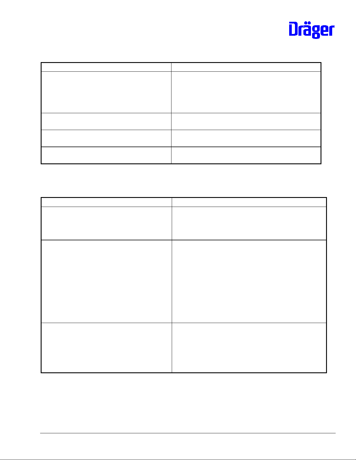
8.2 Electronics module
8.2.0 Table of Contents
Position of the sub-assemblies in the electronics module:
8.2.8
8.2.8
8.2.11
8.2.11
8.2.11
8.2.5
8.2.7
8.2.6
8.2.6
8.2.10
8.2.9
8.2.28.2.38.2.38.2.3 / 8.2.4
8.2.1 (Ink. 8000)
8.2.1 (Inc.8000 SC/IC)
6141.22x Incubator 8000 SC/ IC/NC Repair Information 11.99 Page 28 of 96
Page 29

8.2.1 Keyboards, Inc. 8000 NC/SC/IC
8.2.2 PCB Display Air Temperature
8.2.3 PCB Display (of options), PCB Display Skin
8.2.4 PCB Display Humidity (only Inc. 8000 SC/NC)
8.2.5 PCB CPU and Software-Information
8.2.6 PCB Analog and PCB Filter
8.2.7 PCB Power Pack and Voltage Controller
8.2.8 PCB Motherboard and PCB Fan
8.2.9 PCB Switch
8.2.10 Push Buttons for Height Adjustment (only Inc. 8000)
8.2.11 PCB Controller (RS232)
6141.22x Incubator 8000 SC/ IC/NC Repair Information 11.99 Page 29 of 96
Page 30

8.2.1 Keyboards
8.2.1.0 Table of Contents
8.2.1.1 Information about keyboards used
8.2.1.2 N/A
8.2.1.3 Keyboards Incubator 8000 SC/IC/NC
8.2.1.4 Test
8.2.1.5 Exchange in case of repair
8.2.1.6 Repair information and change status
8.2.1.1 Information about keyboards used
Different keyboards are used in the Incubators:
Incubator 8000 SC/IC/NC:
- Inc. 8000 IC with skin temperature control
- Inc. 8000 IC without skin temperature control
- Inc. 8000 SC/NC with skin temperature control
- Inc. 8000 SC/NC without skin temperature control
The keyboard is connected to the PCB Display Air Temperature and is read out
therefrom. The keyboard is structured like 4 or 3 individual keyboards of Inc. 8000, but
with one cable connection only.
8.2.1.2 N/A
6141.22x Incubator 8000 SC/ IC/NC Repair Information 11.99 Page 30 of 96
Page 31

8.2.1.3 Keyboards of Incubator 8000 SC/IC/NC
The keyboard is to be seen like 3 or 4 individual keyboards.
Pin assignment:
111
Field for air temperature control:
1246
35 7
1
8
7
6
5
4
3
2
S7
S6
S5
S4
S3
S2
S1
6141.22x Incubator 8000 SC/ IC/NC Repair Information 11.99 Page 31 of 96
Page 32

Field for humidity, oxygen and skin temperature:
4
5
6
7
4
21
8
5
3
X
Note: "Foot symbol" key (where fitted) is S4.
Module X = Pin terminal
Skin temperature Pin 9
Oxygen Pin 10
Humidity Pin 11
The keyboard switches can be tested ohmically.
S5
S4
S3
S2
S1
8.1.1.4 Test
All keyboards can be tested ohmically, please refer to 8.1.1.3. In assembled condition the
following tests can be performed:
If a key is identifi ed as being pressed for more than 30 seconds an error storage
(potential INOP or Err-message) is performed.
8.2.1.5 Exchange in case of repair
The keyboards cannot be repaired and must be replaced in case of an error. The following
spare parts are available:
Keyboards of Incubator 8000 IC:
Software version For units Keyboard
20.nn (old) w/o skin-temperature meas. 82 90 470
20.nn (old) with skin-temperature meas.
(1 measurement channel)
Currently 2 possibilities:
- 82 90 467 (discontinued type)
6141.22x Incubator 8000 SC/ IC/NC Repair Information 11.99 Page 32 of 96
Page 33

- 2M 21 681
Important for use of 2M 21 681 in units
which used to have a different keypad:
- Use strip supplied to deactivate
key for second skin-temperature
channel.
- On display PCB (82 90 431) for
skin, remove third LED from top,
as there is no hole for this in the
new keyboard.
21.nn (new) w/o skin-temperature meas. 82 90 470
21.nn (new) with skin-temperature meas.,
1 measurement channel
2M 21 681
Important: Use strip supplied to
deactivate key for second skintemperature channel. Please order the
sticker 2M 21 921 always in addition to
the spare parts keypad or electronics
module for US units with
ThermoMonitoring.
21.nn (new) with skin-temperature meas.,
2 measurement channels
(ThermoView)
2M 21 681
Important: Use strip supplied to
activate key for second skintemperature channel. Please order the
sticker 2M 21 921 always in addition to
the spare parts keypad or electronics
module for US units with
ThermoMonitoring.
Keyboards of Incubator 8000 SC/NC:
Software version For units Keyboard
10.nn (old) w/o skin-temperature meas. For SC and NC with central alarm
LED:
- 2M 21 182
or only for SC (discontinued type) w/o
central alarm LED labeled
„Incubator 8000 SC“:
- 82 90 419
Note: The central alarm LED is not
served by SW 10.nn and is also not
described in operating instructions.
10.nn (old) with skin-temperature meas.
(1 measurement channel)
6141.22x Incubator 8000 SC/ IC/NC Repair Information 11.99 Page 33 of 96
Currently several possibilities:
For SC and NC without central alarm
Page 34

LED:
- 2M 21 180 (discontinued type)
or only for SC (discontinued type) w/o
central alarm LED labeled
„Incubator 8000 SC“:
- 82 90 415
In future for all SC and NC with central
alarm LED:
- 2M 21 691
Important for use of 2M 21 691 in units
which used to have a different
keyboard:
- Use strip supplied to deactivate
key for second skin-temperature
channel.
- On display PCB (82 00 650 or
82 90 431) for skin, remove
third LED from top, as there is
no hole for this in the new keyboard.
Note: The central alarm LED is not
served by SW 10.nn and is also not
described in operating instructions.
11.nn (new) w/o skin-temperature meas. For SC and NC with central alarm
LED:
- 2M 21 182
11.nn (new) with skin-temperature meas.,
1 measurement channel
2M 21 691
Important: Use strip supplied to
deactivate key for second skintemperature channel.
11.nn (new) with skin-temperature meas.,
2 measurement channels
(Thermomonitoring)
2M 21 691
Important: Use strip supplied to
activate key for second skintemperature channel.
6141.22x Incubator 8000 SC/ IC/NC Repair Information 11.99 Page 34 of 96
Page 35

8.2.1.6 Repair information and change status
Re: Change of skin temperature deviation alarm from 0.5 to 1.0 ºC for
all US versions of Incubator 8000 IC with ThermoMonitoring
Reason: All US versions Incubator 8000 IC with ThermoMonitoring for the USA
and Canada will be delivered with a skin temperature deviation alarm
limit of 1.0 ºC according the US version of the Operating Instructions of
the Incubator 8000 IC Software Version 21.n.
Solution: For this change the following modification is necessary:
1. Place a sticker " ± 1 ºC " with the order no. 2M 21 921 on the
keypad of the skin temperature control module directly over the
" ± 0.5 ºC " label.
2. Change the jumper configuration X5 on the Analog PCB 82 90 680
from:
1 1
0.5 ºC to 1.0 ºC
8 8
Devices affected: All Incubators 8000 IC as of software version 21.n in the USA and
Canada.
Additional info: Please order the sticker 2M 21 921 " ± 1 ºC " always in addition to the
spare parts keypad or electronics module.
6141.22x Incubator 8000 SC/ IC/NC Repair Information 11.99 Page 35 of 96
Page 36

8.2.2 PCB Display Air Temperature
8.2.2.0 Table of Contents
8.2.2.1 Information about PCB Display Air Temperature used
8.2.2.2 N/A
8.2.2.3 PCB Display Air Temperature 82 90 411 (Inc. 8000 SC/IC/NC)
8.2.2.4 Test
8.2.2.5 Exchange in case of repair
8.2.2.6 Repair information and change status
8.2.2.1 Information About PCB Display Air Temperature Used
PCB Display Air Temperature 82 90 411 (of Inc. 8000 SC/IC/NC)
With this PCB
In case of repair this PCB can be installed in all Incubators 8000 and 8000 SC/IC/NC,
please refer to 8.2.3.5 "Exchange in case of repair".
8.2.2.2 N/A
all
keyboards of Incubator 8000 and 8000 SC/IC/NC can be connected.
6141.22x Incubator 8000 SC/ IC/NC Repair Information 11.99 Page 36 of 96
Page 37

8.2.2.3 PCB Display Air Temperature 82 90 411
Layout connection side for keyboard:
82 90 411
X2
111
Layout component mounting side:
82 90 411
D1
X1
Configuration:
Position Component
X1 Connection to motherboard
X2 Connection to keyboard
D1 Keyboard and display driver 18 20 877
8.2.2.4 Test
6141.22x Incubator 8000 SC/ IC/NC Repair Information 11.99 Page 37 of 96
Page 38

Displays:
All displays, except for the mains failure LED can tested with the air temperature
module by pressing the "Check" key. The LED mains failure only lights up in case of
mains failure and the operational LED li ghts up as soon as the unit is switched on. In
the case of an error in the keyboard and display driver an INOP message is given.
Keyboard evaluation:
The keys can be simulated by short-circuiting of connecti ons (keys) at connector X2,
please also refer to 8.2.1.2 and 8.1.2.3. When short-circuiting the keys or in the event
of a short-circuit on the PCB for more than 30 seconds an error is stored (does not
apply to SW 0.4 of Inc. 8000).
8.2.2.5 Exchange in case of repair
- PCB Display Air Temperature 82 90 411
8.2.2.6 Repair information and change status
1. Manufacturing fault in the PCB Display Air Temperature 82 90 411 08.94
Description: Contact problems between this board and the PCB Motherboard due to
soldering agent vapors at the plug-in connector X1. The fault is visible at
the plug-in connector:
OK = contacts are gleaming gold
Not OK= contacts are silver gray
Devices
affected: Incubators 8000 SC/IC manufactured between June '92 and end '93.
Measures: No preventive check required since this fault has reportedly occurred only
once so far (August 94). Should this type or fault occur, then replace the
board.
6141.22x Incubator 8000 SC/ IC/NC Repair Information 11.99 Page 38 of 96
Page 39

8.2.3 PCB Display (of options), PCB Display Skin (as of SW 11 and 21)
8.2.3.0 Table of Contents
8.2.3.1 Information about PCBs Display used
8.2.3.2 PCB Display 82 00 431 / 82 90 650 / 82 90 691
8.2.3.3 Functional adjustment for humidity, oxygen and skin temperature
8.2.3.4 Exchange in case of repair
8.2.3.5 Test
8.2.3.6 Repair instructions and change status
8.2.3.1 Information about PCBs Display used
Incubator 8000 SC/IC/NC:
- PCB Display 82 90 431
- PCB Display Skin 82 90 691
(with SW 11.nn and 21.nn)
PCB Display Skin 82 90 691 is only intended for skin temperature. It is required with SW 11.nn
and 21.nn.
6141.22x Incubator 8000 SC/ IC/NC Repair Information 11.99 Page 39 of 96
Page 40

8.2.3.2 PCB Display 82 90 431
Layout connection side keyboard:
82 00 650 / 82 90 431
X2
16
Layout configuration side:
82 00 650 / 82 90 431
D1
S7 S8 S9
X1
S1 - S6
Configuration:
Position Component
X1 Connection to motherboard
X2 Connection to keyboard of Inc. 8000, unassigned in Inc.
8000 SC/IC/NC
D1 Keyboard and display driver
S1 to S9 Option switch or soldering bridges, refer to 8.2.3.3
6141.22x Incubator 8000 SC/ IC/NC Repair Information 11.99 Page 40 of 96
Page 41

8.2.3.3 Functional adjustment for humidity, oxygen and skin temperature
Before installing the PCB Displays, it is necessary to adjust the function of the board using the
switches or the soldering bridges S1 to S9. The soldering bridges are located at the same
point as the switches.
Skin temperature Oxygen Humidity
S7 S8 S9
S7 S8 S9
S7 S8 S9
X1
S1 - S6
X1
S1 - S6
X1
S1 - S6
S1, S4 and S7 closed S2, S5 and S8 closed S3, S6 and S9 closed
8.2.3.4 Exchange in case of repair
- PCB Display 82 90 431
- PCB Display Skin 82 90 691
The new PCB Display Skin 82 90 691 is required if the Incubator features the PCB
Analog 82 90 680 with SW 11.nn or 21.nn. The difference with respect to the old PCB
Display 82 90 431 is that there is a differently positioned LED for the additional key for
readout of the second skin-temperature channel. This new PCB Display Skin 82 90 691
can be used on all units IC/SC/NC for skin temperature.
8.2.3.5 Test
The display is tested as described in 8.2.2.4 "Test of PCB Display Air Temperature". Note:
The keyboards for the options of Incubator 8000 are connected to this PCB, but evaluations
takes place on the PCB Display Air Temperature.
6141.22x Incubator 8000 SC/ IC/NC Repair Information 11.99 Page 41 of 96
Page 42

8.2.3.6 Repair instructions and change status
1. Manufacturing fault in the PCB Display 82 90 431 08.94
Description: Display flickers or INOP with display error has occurred.
Cause: Contact problems between this board and the PCB Motherboard due to
soldering agent vapors at the plug-in connector X1. The fault is visible at
the plug-in connector:
OK = contacts are gleaming gold
Not OK = contacts are silver gray
Devices
affected: Incubators 8000 SC/IC manufactured between June '92 and end '93.
Measures: No preventive check required since this fault has reportedly occurred only
once so far (August 94) on the PCB Display Air Temperature 82 90 411.
Should this type or fault occur, then replace the board.
2. Soldering switches replace DIL switches 08.94
As of end 94, the option switches S1 to S9 will be replaced with soldering switches,
refer to 8.2.3.5.
8.2.4 PCB Display Humidity (only Inc. 8000 SC/NC)
8.2.4.0 Table of Contents
8.2.4.1 Description PCB Display Humidity 82 90 451
8.2.4.2 Exchange in case of repair
8.2.4.3 Repair information and change status
8.2.4.1 Description of PCB Display Humidity
The PCB Display Humidity is almost identical with the PCB Display 82 90 431, but the LEDs,
switches and 7-segment displays for Inc. 8000 SC not used are not fitted. Test and layout plan
are identical with PCB Display, refer to 8.2.3. The switch or the soldering bridge S9 must be
adjusted or bridged as described in 8.2.3.3. The switches S1 to S8 (if available) remain open.
8.2.4.2 Exchange in case of repair
6141.22x Incubator 8000 SC/ IC/NC Repair Information 11.99 Page 42 of 96
Page 43

For repair of the PCB Display Humidity the following spare part may be used:
- PCB Display Humidity 82 90 431
8.2.4.3 Repair information and change status
1. Manufacturing fault in the PCB Display Humidity 82 90 431 08.94
Description: Display flickers or INOP with display error has occurred.
Cause: Contact problems between this board and the PCB Motherboard due to
soldering agent vapors at the plug-in connector X1. The fault is visible at
the plug-in connector:
OK = contacts are gleaming gold
Not OK = contacts are silver gray
Devices
affected: Incubators 8000 SC/IC manufactured between June '92 and end '93.
Measures: No preventive check required since this fault has reportedly occurred only
once so far (August 94) on the PCB Display Air Temperature 82 90 411.
Should this type or fault occur, then replace the board.
2. Soldering switches replace DIL switches 08.94
As of end 94, the option switch S9 will be replaced with a soldering switch, refer to
8.2.3.3. This connection must be closed, S1 to S8 must remain open.
6141.22x Incubator 8000 SC/ IC/NC Repair Information 11.99 Page 43 of 96
Page 44

8.2.5 PCB CPU
8.2.5.0 Contents
8.2.5.1 Information about PCB CPUs used
8.2.5.2 PCB CPU Standard 2
8.2.5.3 PCB CPU Incubator
8.2.5.4 Test
8.2.5.5 Exchange of PCB CPU in the case of repair
8.2.5.6 Repair information software
8.2.5.7 Repair information and modification states
8.2.5.1 Information about PCB CPUs used
Two different PCB CPUs can be used in Incubator 8000 SC/IC/NC.
PCB CPU Standard 2 (83 05 141)
A Standard-CPU, which is used in several Dräger-devices, e.g. in Incubator 8000 series
and EVITA. In the incubator many functions of this PCB are not used..
PCB CPU Incubator 8000 (82 90 571)
A modified version of the PCB CPU Standard 2, in which components which are not
used are not fitted, e.g. the battery for retention of data. This PCB can only be used in
Incubator 8000 and Incubator 8000 SC/IC/NC.
Note:
replaced by a modification status "≥ 01", see IDM no. 15 or TSB no. 12.
In the event of repairs both versions can be used. The different fittings are described in in
8.2.5.2 and 8.2.5.3, also refer to 8.2.5.5 "Exchange of PCB CPU in the case of repair.
The PCB CPU Incubator 82 90 571 with the modification status "00" is being
6141.22x Incubator 8000 SC/IC/NC Repair Information 11.99 Page 44 of 96
Page 45

8.2.5.2 PCB CPU Standard 2 (83 05 141)
Layout plan (Drawing shows configuration with software 1x.xx or 2x.xx.):
T2
(GND)
B1
CPU Standard 2
T1
(5V)
X7
D14
D13
X6
D6
X5
X4 X3 X2
D1
D12
D11 D10 D9
X1
Configuration of jumper fields with jumper 18 14 508:
R1
LED V11
D8
X8
SW 0.4
Position SW 1.xx, 1x.xx or 2x.xx
X2 not fitted
X3 not fitted
X4 not fitted
X5 1-2, 3-4 (like drawing)
X6 1-18, 4-15, 8-11 (like drawing)
X7 not fitted
X8 3-4 (like drawing)
Configuration of components:
6141.22x Incubator 8000 SC/ IC/NC Repair Information 11.99 Page 45 of 96
Page 46

Component
and Position
D1 Microprocessor 18 09 156
D6 Address decoder 83 04 920
D8 Time-Keeper-RAM 18 28 142
D9 not fitted
D10 not fitted
D11 not fitted
D12 EPROM, see 8.2.5.5
D13 Timer 18 13 900
D14 not fitted
B1 not fitted
Calibration of voltage comparator:
The voltage comparator on the PCB CPU Standard 2 is not required for
Incubator 8000 SC/IC/SC, potentiometer R1 must be turned right until it stops
(clockwise).
SW 1x.xx or 2x.xx
(Pin 1 of component into Pin 3 of
base)
Note: If after use of this PCB in the incubator it shall be used in a
different device (e.g. Evita) the voltage comparator must be
calibrated to the value of the respective unit before.
6141.22x Incubator 8000 SC/ IC/NC Repair Information 11.99 Page 46 of 96
Page 47

Function of LED V11
LED Cause Remedy
off or glows slightly normal condition
off or glows slightly,
but unit shows
sporadic INOP-errors
without storage of
INOP error numbers
LED lights up, device
indicates INOP
- +5V-supply defective
(unstable)
- Voltage comparator incorrectly
adjusted
- Watchdog-error
- Voltage comparator incorrectly
adjusted
- +5V-supply too low
- Test of +5V-voltage on the
PCB CPU between T1 and T2:
test value V = 4,8 to 5,2V
- Check voltage comparator on
PCB CPU
Replace PCB CPU
-
- Check voltage comparator on
PCB CPU
- Check of +5V-voltage
on PCB CPU between T1
and T2,
Test value V = 4,8 to 5,2V
6141.22x Incubator 8000 SC/ IC/NC Repair Information 11.99 Page 47 of 96
Page 48

8.2.5.3 PCB CPU Incubator 8000 (82 90 571)
Note:
by a modification status "≥ 01", see IDM no. 15 or TSB no. 12.
Layout plan:
The PCB CPU Incubator 82 90 571 with the modification status "00" is being replaced
X20
T2
(GND)
CPU Incubator 8000
X19
D13
X6
D6
X5
T1
(5V)
LED V11
D1
D12
X1
Configuration of jumper fields with jumper 18 14 608:
Position Software 1.xx, 1x.xx or 2x.xx
X5 1-2, 3-4 (like drawing)
X6 1-18, 4-15, 8-11 (like drawing)
X8 3-4 (like drawing)
X19 1-2 (like drawing)
X20 1-2 (like drawing)
D8
X8
6141.22x Incubator 8000 SC/IC/NC Repair Information 11.99 Page 48 of 96
Page 49

Component configuration:
Component and Position Software 1.xx, 1x.xx, 2x.xx
D1 Microprocessor 18 09 156
D6 Address decoder 83 04 920
D8 Time-Keeper-RAM 18 28 142 (Pin 1 of component in
Pin 3 of base)
D12 EPROM, see 8.2.5.6
D13 Timer 18 13 900
B1 (not shown) Battery not provided, SW 0.4 not possible
Calibration:
Not required.
Function of LED V11:
LED Cause Remedy
LED off or glows slightly normal condition
LED lights up, incubator
switches to INOP
- Power-On-Reset on
PCB CPU (N22) defective
Replace PCB CPU
-
immediately after switch-on
- Jumper X19 missing
LED lights up, Incubator O.K. - Voltage comparator N22
- Check jumper
Replace PCB CPU
-
defective
6141.22x Incubator 8000 SC/ IC/NC Repair Information 11.99 Page 49 of 96
Page 50

8.2.5.4 Test
The test is performed by the operation software, the errors are listed in the error list, if
technically possible and can be read out.
The following error description indicates a CPU error:
- Device goes to INOP immediately after switch-on. In this case first of all check all
operating voltages, please refer to 6, troubleshooting.
- LED on the PCB CPU lights up, see function of LED in 8.2.5.2 and 8.2.5.3.
8.2.5.5 Exchange of PCB CPU in case of repair
Note:
by a modification status "≥ 01", see IDM no. 15 or TSB no. 12.
PCB CPU Standard 2 (less useful)
The PCB CPU Incubator 82 90 571 with the modification status "00" is being replaced
The following components are required for repair:
- PCB CPU Standard 2 83 05 141
- Timer 18 13 900
- RAM (only for SW 0.4) 18 17 426
- Time-Keeper-RAM 18 28 142
(for SW 1.xx, 1x.xx or 2x.xx)
- Address-Decoder 83 04 920
- Jumper 18 14 508
(to be taken from the defective PCB CPU)
- EPROM see 8.2.5.6 or spare parts list
Note: With SW version 1.xx, 1x.xx or 2x.xx battery B1 must be unsoldered.
6141.22x Incubator 8000 SC/IC/NC Repair Information 11.99 Page 50 of 96
Page 51

PCB CPU Incubator (useful)
The following components are required for exchange:
- PCB CPU Incubator 82 90 571
- Time-Keeper-RAM 18 28 142
- EPROM see 8.2.5.6 or spare parts list
- Jumper 18 14 508
(are to be taken from defective PCB CPU)
Note:
replaced by a modification status "≥ 01", see IDM no. 15 or TSB no. 12.
The PCB CPU Incubator 82 90 571 with the modification status "00" is bei ng
8.2.5.6 Repair information software
Important: When performing repairs, software version is not to be upgraded from 10.nn
to 11.nn or from 20.nn to 21.nn. Exception: Retrofitting with ThermoMonitoring set.
These units have different operating instructions. Please note: SW 11.n is not available
for US versions!
Comparison of new software versions 11.nn (SC/NC) and 21.nn (IC) with old software versions
10.nn and 20.nn
Incubator 8000 IC with skin-temperature measurement
Assembly SW 21.nn (new) SW 20.nn (old)
Analog PCB Order no. 82 90 680
Connection of 1 or 2 skintemperature sensors is by way of
wiring harness on left of basic
housing. Recognition of 1 or 2
sensors is via the wiring harness
which has its own connector
separate from the other sensor
connections.
Range: 30 to 42 °C
Climate sensor 2M 21 688
without skin temperature connection
Order no. 82 00 920
Connection of skin-temperature
sensor on IC is to climate sensor.
Range: 33 to 38 °C.
82 90 380 with skin temperature
connection
Keyboard New keyboard 2M 21 681 with
additional key for readout of second
skin-temperature channel. If key is
6141.22x Incubator 8000 SC/ IC/NC Repair Information 11.99 Page 51 of 96
Use can be made of either the old or
the new keyboard
Page 52

not needed due to absence of
thermomonitoring option, the key
position is covered with a strip.
Skin display
PCB
New skin display PCB 82 90 691
with LED at different position for
Use can be made of old or new
Display PCB
additional key requi red for readout
of optional second skin-temperature
channel.
Incubator 8000 IC without skin-temperature measurement
Assembly SW 21.nn (new) SW 20.nn (old)
Climate sensor 2M 21 688 without skin temperature
connection
82 90 380 with skin temperature
connection
Incubator 8000 SC/NC with skin-temperature measurement
Assembly SW 11.nn (new) SW 10.nn (old)
Analog PCB Order no. 82 90 680
Connection of 1 or 2 skintemperature sensors is by way of
wiring harness on left of basic
Order no. 82 00 920
Skin-temperature sensor is
connected on back of unit.
Range: 33 to 38 °C.
housing. Recognition of 1 or 2
sensors is via the wiring harness.
Keyboard New keyboard 2M 21 691 with
additional key for readout of second
skin-temperature channel. If key is
not needed due to absence of
Use can be made of either the old or
the new keyboard. An alarm LED
(central alarm) is not actuated even
if it is fitted.
ThermoMonitoring option, key
position is covered with a strip.
Additional feature: Alarm LED
(central alarm).
Skin display
PCB
New skin display PCB 82 90 691
with LED at different position for
Use can be made of old or new
Display PCB.
additional key needed for readout of
optional second skin-temperature
channel.
6141.22x Incubator 8000 SC/ IC/NC Repair Information 11.99 Page 52 of 96
Page 53

Incubator 8000 SC/NC without skin-temperature measurement
No fundamental changes in terms of function between SW 10.nn and 11.nn, however
different operating instructions.
Assembly SW 11.nn (new) SW 10.nn (old)
Keyboard with central alarm no central alarm
The following software versions apply to the units:
Incubator 8000 IC with software 20.nn:
- SW 20.00 allowed, but no longer available
Is replaced by SW 20.01 (errors must be identified three times consecutively to lead to
an Err- or INOP error). Principle exchange is not intended, but useful should errors
occur sporadically.
- SW 20.01 allowed, but no longer available
- SW 20.02 allowed, but no longer available
Are replaced by SW 20.03: Service mode "A" has been included (vol tage A/D test
channel), skin-temp. mode up to 39 °C (previously 37 °C), additional alarm delay of 90 s
for O2-measurement after swiveling climate sensor in, 2nd skin temp. channel provided
by software (hardware is being prepared).
- SW 20.03 allowed, but no longer available
- SW 20.04 2M 22 327
Incubator 8000 SC/NC with SW 10.nn:
- SW 10.00 not released
- SW 10.01 / 10.02 all owed, but no longer available
Are replaced by SW 10.03 (errors must be identified three times consecutively to lead
to an Err- or INOP error). A principle exchange is not intended, but useful should errors
occur sporadically.
- SW 10.03 allowed, but no longer available
6141.22x Incubator 8000 SC/ IC/NC Repair Information 11.99 Page 53 of 96
Page 54

Is replaced by SW 10.04: Service mode "A" has been included (voltage A/D test
channel), skin-temp. mode up to 39 °C air temperature (previously 37 °C).
- SW 10.04 allowed, but no longer available
- SW 10.05 2M 22 326
Incubator 8000 IC with software 21.nn:
- SW 21.02 2M 22 331
Incubator 8000 SC/NC with SW 11.nn (not available for US versions):
- SW 11.02 2M 22 332
6141.22x Incubator 8000 SC/ IC/NC Repair Information 11.99 Page 54 of 96
Page 55

8.2.5.7 Repair information and modification states
1. New PCB CPU Incubator 01.93
From the beginning of 1993 all Incubators 8000 SC/IC/NC will include the new PCB
CPU Incubator 83 05 141. This PCB CPU replaces the current PCB CPU Standard 2. In
case of repair both versions can be used, since the PCB CPU Incubator is a simplified
version of PCB CPU Standard on which unused components are not fitted. Also refer to
8.2.5.5 "Exchange of PCB CPU in case of repair".
Note:
replaced by a modification status "≥ 01", see IDM no. 15 or TSB no. 12.
The PCB CPU Incubator 82 90 571 with the modification status "00" is being
6141.22x Incubator 8000 SC/IC/NC Repair Information 11.99 Page 55 of 96
Page 56

8.2.6 PCB Analog with PCB Filter
8.2.6.0 Table of Contents
8.2.6.1 Information about PCBs used
8.2.6.2 PCB Analog 82 00 770 / 82 00 920 with PCB Filter 83 02 526
(layout up to mid 95)
8.2.6.3 PCB Analog 82 00 770 / 82 90 920 / 82 90 680
(layout as of mid 95)
8.2.6.4 Test and Calibration PCB Analog 82 00 770 / 82 00 920 / 82 90 680
8.2.6.5 N/A
8.2.6.6 Exchange of PCB Analog in case of repair
8.2.6.7 Repair information and change status
8.2.6.1 Information about PCBs used
3 different PCBs are currently in use in Incubator 8000 and 8000 SC/IC/NC.
Incubators without skin temperature control:
- PCB Analog 82 00 770
Note: partly fitted PCB Analog 82 00 920 without skin temperature amplifier.
Incubators with skin temperature control:
- PCB Analog 82 00 920
Note: Until end of 1992 the units including PCB Analog 82 00 920 were equipped with a
PCB Filter Circuit 83 02 526. During repair thi s PCB Filter Circuit may be removed and
replaced by two jumpers on the PCB Analog 82 00 920, please refer to 8.2.6.2.
Only for SW 11.nn or 21.nn:
- PCB Analog 82 90 680
6141.22x Incubator 8000 SC/ IC/NC Repair Information 11.99 Page 56 of 96
Page 57

8.2.6.2 PCB Analog 82 00 770 / 82 00 920 with PCB Filter 83 02 526 (layout
up to mid 95)
Layout: (the figure below shows PCB Analog 82 00 920 fully equipped):
(X3)
K1
X5
N19 N18
R24
R81
25
26
1
1
2
R7
X4
X2
R15R69R67
R4
R19R12
R55
R83
D1
R60R31
R75
R71
D2
K2
82 00 770 / 82 00 920
X1
6141.22x Incubator 8000 SC/ IC/NC Repair Information 11.99 Page 57 of 96
Page 58

Configuration:
Position Component or function
X1 Connection to PCB Motherboard
X2 Connection to climatic sensor (Inc. 8000 and Inc. 8000
IC) or to air temperature sensor
(Inc. 8000 SC/NC)
X3 not used
X4 26 test points
X5 Connection to PCB Filter Circuit with PCB Analog 82
00 920. If no PCB Filter Circuit is i nstalled, jumpers
from X5/1 to X5/4 and from X5/2 to X5/5 must be
soldered on the back.
D1 Multiplexer 18 23 345
D2 A/D-converter 18 23 256
K1, K2 (K1 not with 82 00 770) Relay 18 13 714
N18 Voltage controller +5 V 18 21 458
N19 Voltage controller -5 V 18 23 337
Potentiometer R4 Calibration of air temperature amplifier
Potentiometer R7 Calibration of air temperature amplifier
Potentiometer R12 Calibration of overtemperature amplifier
Potentiometer R15 Calibration of overtemperature amplifier
Potentiometer R19 Calibration of overtemperature comparator 40°C
R24 Calibration of skin temperature amplifier
R31 Calibration of skin temperature amplifier
R60 no function
Potentiometer R67 no function
Potentiometer R69 no function
R71 Calibration of A/D converter
Potentiometer R75 Calibration of A/D converter
Potentiometer R81 no function
R55 / R83 Voltage divider A/D test channel
Calibration:
see 8.2.6.4
6141.22x Incubator 8000 SC/ IC/NC Repair Information 11.99 Page 58 of 96
Page 59

Repair information:
1 . Repair information error 19 and 65
Whenever the PCB Analog 82 00 770 / 82 00 920 or the voltage regulator for + 15 V or
- 15 V or the PCB Power Pack 82 90 461 is replaced the A/D test channel must be
checked and calibrated, if necessary, please refer to 8.2.6.4.
6141.22x Incubator 8000 SC/ IC/NC Repair Information 11.99 Page 59 of 96
Page 60

8.2.6.3 PCB Analog 82 00 770 / 82 90 920 / 82 90 680 (layout as of mid
95)
Layout: (the figure below shows PCB Analog 82 00 920 / 82 90 680 fully equipped):
R31
X6
R125
V40V39
X5
R24
1
1
8
25
26
1
2
R7
X4
X2
R15
R4
R19R12
R83
R55
D1
R75
R71
D2
T3 T1 T2
82 00 770 / 82 00 920 / 82 90 680
X1
Important:
- LED V40 lights if - 5 V for AD converter is available. This voltage is stepped down from
the - 15 V.
- LED V39 lights if + 5 V for AD converter is available. This voltage is stepped down from
the + 15 V.
Calibration: see 8.2.6.4
6141.22x Incubator 8000 SC/ IC/NC Repair Information 11.99 Page 60 of 96
Page 61

Important: Repair information, errors 19 and 65
On replacing PCB Analog 82 00 770 / 82 00 920 / 82 90 680 or voltage regulator for + 15 V or
- 15 V or PCB Power Pack 82 90 461 A/D test channel must always be checked and if
necessary calibrated, see 8.2.6.4.
Wiring harness, skin temperature (82 90 680 only):
This is the side connection for skin-temperature sensors with cable link to PCB Analog
82 90 680. Important: With this PCB, skin-temperature sensor(s) is/are attached to
connector X6.
X6 X6
1
Sensor 1 Sensor 1
1
Sensor 2
*
*
7
1
X5
1
8
25
26
X6
X4
1 skin-temperature connection:
- Wiring harness, complete (with socket) 2M 21 738
2 skin-temperature connections:
X2
7
1
2
R7
- Wiring harness, complete (with socket) 2M 21 738
extended with
- (*) Thermomonitoring option (with 2nd socket) 2M 21 733
(incl. ThermoView PC program 2M 21 888)
6141.22x Incubator 8000 SC/ IC/NC Repair Information 11.99 Page 61 of 96
Page 62

Important:
Al l US versions Incubator 8000 IC with ThermoMonitoring for the USA and
Canada will be delivered with a skin temperature deviation alarm limit of 1.0
ºC according the US version of the Operating Instructions of the Incubator
8000 IC Software Version 21.n.
For this change the following modification i s necessary:
1. Place a sticker " ± 1 ºC " with the order no. 2M 21 921 on the keypad of
the skin temperature control module directly over the " ± 0.5 ºC " label.
2. Change the jumper configuration X5 on the Analog PCB 82 90 680 from:
1 1
8 8
0.5 ºC to 1.0 ºC
6141.22x Incubator 8000 SC/ IC/NC Repair Information 11.99 Page 62 of 96
Page 63

8.2.6.4 Test and Calibration of PCB Analog
Table of Contents
a Test equipment required
b Test of operating voltages
c Calibration of A/D test channel
d Calibration of air temperature amplifier
e Calibrati on of excess-temperature amplifier and excess-temperature comparator
f Calibration of skin temperature amplifier
g Test of O2-inputs and O2 comparators
h Calibration of A/D converter
:
a Test equipment required
- Multimeter 79 01 021
- Measuring adapter Incubator 8000 79 01 471 or
- Testboard uni 40 79 00 610
- Sensor simulator Incubator 8000 (for d, e , g, and e) 79 01 240
- Skin temperature sensor simulator (for f) 79 01 236
- 2 decade resistors (for f and e) 79 01 146
6141.22x Incubator 8000 SC/ IC/NC Repair Information 11.99 Page 63 of 96
Page 64

b Test of operating voltages
Unit is open, but ready for operation. Switch on Incubator. To facilitate measurement the
measuring adapter 79 01 471 can be connected to terminal strip X4.
Measurement of voltages at terminal strip X4:
TP 25 (+ 5 V, of PCB Power Pack) ⇒ TP 26 (GNDD): V = + 5,0 ± 0,2 V
TP 18 (+ 15 V, of PCB Power Pack) ⇒ TP 26 (GNDD): V = + 15,0 V ± 0,6 V
TP 22 (- 15 V, of PCB Power Pack) ⇒ TP 26 (GNDD): V = - 15,0 V ± 0,6 V
TP 20 (+ 5 V, generated on PCB Analog) ⇒ TP 21 (GNDA): V = + 5,0 V ± 0,4 V
TP 24 (- 5 V, generated on PCB Analog) ⇒ TP 21 (GNDA): V = - 5,0 V ± 0,4 V
c Calibration of A/D test channel
Important: As of SW 10.04 (Inc. 8000 SC/NC) and SW 20.03 (Inc. 8000 IC) it is possible to
read out this voltage directl y in mV in service mode "A", see 6.2.2.11.
Unit is open, but ready for operation. Switch on unit and wait for self-test.
Read out voltage of A/D test channel:
- In service mode "A"
or
- Measure the A/D test channel voltage at the multiplexer D1 between Pin 2 (test voltage)
and Pin 12 (GNDA) using a quick multimeter (79 01 021, Soar or BBC).
R19R12
R83
R55
R75
R71
D2
K2
D1
V
6141.22x Incubator 8000 SC/ IC/NC Repair Information 11.99 Page 64 of 96
Page 65

Measurement is performed after the self-test (approx. 35 seconds), but the device must not be
in INOP condition. In the event of an INOP error 65 or 19 follow the calibration instructions.
Test value: The A/D test channel test voltage is the lower voltage with the multiplexer
switched through.
V = 4.4 ± 0.3 V
Calibration instructions:
In the event of deviations from the test value the voltage divider R55 / R83 must be modified:
Important: The new layout as of approx. mid 95 features soldering terminals for calibration of
the AD converter test voltage:
T1 (AD test) and T2 (+15 V) are in parallel with R55
T1 (AD test) and T3 (-15 V) are in parallel with R83
- Voltage too low or error 65:
Increase voltage by means of additional resistor in series with R83 and repeat test,
recommendation: approx. 2kohm.
- Voltage too high or error 19:
Reduce voltage by means of additional resistor in series with R55 and repeat test,
recommendation approx. 1kohm.
d Calibration of air temperature amplifier
- Connect sensor simulator Incubator 8000 (79 01 240) to X2.
- The sensor simulator must have the following basic setting:
o Temperature = 35 °C
o Humidity = 70 %
o Sensor = 1
- Switch on incubator and wait for 35 second self-test.
- Measure voltage between X4/3 and X4/21 (GNDA)
- Set voltage to V = 625 mV ± 0,5 mV using potentiometer R7
- Measure voltage between X4/4 and X4/21 (GNDA)
6141.22x Incubator 8000 SC/ IC/NC Repair Information 11.99 Page 65 of 96
Page 66

- Use potentiometer R4 to set the voltage to V = 2,917 V ± 0,005 V
- Indication on actual value display air temperature = 35,0 °C ± 0,1 °C
- Set sensor simulator to 25,0 °C
- Indication on actual value display air temperature = 25,0 °C ± 0,2 °C
- Set sensor simulator to 45,0 °C
- Indication on actual value display air temperature = 45,0 °C ± 0,2 °C
e Calibration of excess temperature amplifier and excess temperature
comparator
- Connect sensor simulator Incubator 8000 (79 01 240) to X2
- The sensor simulator must have the following basic setting:
o Temperature = 35 °C
o Humidity = 70 %
o Sensor = 1
- Switch incubator on and wait for 35 seconds self-test
- Call up service mode 5, please refer to 6.3 service mode
- Measure voltage between X4/6 and X4/ 21 (GNDA)
- Use potentiometer R15 to set the voltage to 625 mV ± 0,5 mV
- Measure voltage between X4/8 and X4/21 (GNDA)
- Use potentiometer R12 to set the voltage to 3,500 V ± 0,005 V
- Indication on actual value display air temperature = 35,0 °C ± 0,1 °C
- Set sensor simulator to 25 °C
- Indication on actual value display air temperature = 25,0 ± 0,2 °C
- Set sensor simulator to 45 °C
- Indication on actual value display air temperature = 45,0 °C ± 0,2 °C
6141.22x Incubator 8000 SC/ IC/NC Repair Information 11.99 Page 66 of 96
Page 67

- Set sensor simulator to 40 °C
- Measure voltage between X4/7 and X4/21 (GNDA)
- Use potentiometer R19 to set the voltage such that it changes from negative value to
positive value
- Set sensor simulator to 39,7 °C (or 39,5 °C)
- Negative voltage (- 12 V to - 15,6 V)
- Set sensor simulator to 40,2 °C (or 40,5 °C)
- Positive voltage (+ 12 V to + 15,6 V)
f Calibration of skin temperature amplifier
- Connect sensor simulator Incubator 8000 (79 01 240) to X2
- Connect skin temperature sensor simulator (79 01 236) to sensor simulator
Incubator 8000
The sensor simulator Incubator 8000 must have the following basic setting:
o Temperature = 35 °C
o Humidity = 70 %
o Sensor = 1
The skin temperature sensor simulator must have the following basic setting:
o Temperature = 36.0 °C
o Sensor connected/not connected (82 90 680 only)
- Only for 82 90 680:
Connect pin X1/29c to GND. GND is e.g. X1/32a or X1/32b.
- Switch incubator on and wait for 35 second self-test
- Measure voltage between X4/17 and X4/21 (GNDA)
- Connect a decade resistor (initial value for 82 00 920 approx. 40 K ohm, for 82 90 680
approx. 5 K ohm) to the soldering tags of R24 and adjust such that the voltage is:
308.6 mV ± 0.5 mV for 82 00 920 or
385.5 mV ± 0.5 mV for 82 90 680
6141.22x Incubator 8000 SC/ IC/NC Repair Information 11.99 Page 67 of 96
Page 68

- Solder the set resistance value to exactly 10 Ohm to the soldering tags of R24 (i f
applicable, 2 resi stors connected in series or in parallel)
- Check calibration
- Measure voltage between X4/11 and X4/21 (GNDA)
- Connect a decade resistor (initial value for 82 00 920 approx. 5 K ohm, for 82 90 680
approx. 150 K ohm) to the soldering tags of R31 (82 00 920) or R125 (82 90 680) and
adjust such that the voltage is:
2.857 V ± 0.010 V for 82 00 920 or
2.500 V ± 0.010 V for 82 90 680
- Solder the set resistance value to exactly 10 Ohm to the soldering tags of R31 (i f
applicable, 2 resi stors connected in series or in parallel)
- Check calibration
- Indication on actual value display skin temperature. = 36,0 °C ± 0,1 °C
- Set skin temperature sensor simulator to 33,2 °C
- Indication on actual value display skin temperature = 33,2 °C ± 0,2 °C
- Set skin temperature sensor simulator to 37,8 °C
- Indication on actual value display skin temperature = 37,8 °C ± 0,2 °C
- Press key "Check 36,0 °C" in skin temperature module
- Indication on actual value display air temperature = 36,0 °C ± 0,1 °C
- Only for 82 90 680:
Remove connection between pin X1/29c and GND.
g Test of O2 inputs and O2 comparators
- Connect sensor simulator Incubator 8000 (79 01 240) to X2
- The sensor simulator must have the following basic setting:
o Temperature = 35 °C
o Humidity = 70 %
6141.22x Incubator 8000 SC/ IC/NC Repair Information 11.99 Page 68 of 96
Page 69

o Sensor = 1
- Switch on incubator and wait for 35 second self-test
- A potential excess-temperature warning can be switched off by pressing the "Reset
Excess-temperature" key
- Set O2-voltages at sensor simulator to 50 mV ± 1 mV each using the two
potentiometers. The voltages can be measured at the sensor simulator below the
potentiometers.
- Measure voltage between X4/1 and X4/21 (GNDA),
Test value = 1,97 V ± 0,05 V
- Measure voltage between X4/5 and X4/21 (GNDA),
Test value = 0,72 V ± 0,02 V
- Set both O2-voltages at sensor simulator to 10 mV ± 0,5 mV
- Measure voltage between X4/12 and X4/21 (GNDA),
Test value ≤ 0,1 V
- Reduce O2-voltage A to 1 mV
- Test value ≥ 11 V
- Set O2-voltage A to 10 mV ± 0,5 mV
- Test value ≤ 0,1 V
- Set O2-voltage B to 1 mV
- Test value ≥ 11V
- Set O2-voltage B to 10 mV ± 0,5 mV
- Test value ≤ 0,1 V
h Calibration of A/D-converter
- Connect sensor simulator Incubator 8000 (79 01 240) to X2
- The sensor simulator must have the following basic setting:
6141.22x Incubator 8000 SC/ IC/NC Repair Information 11.99 Page 69 of 96
Page 70

o Temperature = R ext.
o Humidity = 70 %
o Sensor = 1
- Connect a decade resistor for "R ext. Excess-.temperature" at the sensor simulator.
- Switch incubator on and wait for 35 second self-test.
- Call service mode 5, please refer to 6.3 Service-Mode
- Measure voltage between X4/8 and X4/21 (GNDA)
- Set the voltage to 0 mV + 1 mV by means of the decade resistor.
- Use potentiometer R75 to set the zero point of the A/D-converter such that the actual
value display just changes from 0,0 °C to 0,1 °C
- Set voltage to 5,000 V ± 0,001 V by means of the decade resistor.
- Connect another decade resistor to the soldering tags of R71 and adjust such that the
actual value display just changes from 49,9 °C to 50,0 °C.
- Solder the set resistance to soldering tags of R71 (if applicable, 2 resistors connected
in series or parall el)
Check calibration at:
o 5,00 V = 50,0 °C ± 0,1 °C
o 4,00 V = 40,0 °C ± 0,1 °C
o 3,00 V = 30,0 °C ± 0,1 °C
o 2,00 V = 20,0 °C ± 0,1 °C
o 0,00 V = 0,0 °C ± 0,1 °C
8.2.6.5 N/A
6141.22x Incubator 8000 SC/ IC/NC Repair Information 11.99 Page 70 of 96
Page 71

8.2.6.6 Exchange of PCB Analog in case of repair
Important: When replacing PCB Analog, A/D test channel must be checked and if necessary
calibrated, see 8.2.6.4.
Important: In the case of PCBs with the new layout, the PCB Filter for the skin-temperature
sensor cannot be connected and is also not necessary.
In case of repair the following spare parts may be used:
Incubators with skin temperature control:
- Only for SW 10.nn / 20.nn:
° PCB Analog 82 00 920
Note: If there is no filter circuit, two jumpers must be soldered onto the PCB Analog with
layout up to 06.95, please refer to the configuration X5 under 8.2.6.1.
- Only for SW 11.nn / 21.nn:
° PCB Analog 82 90 680
Incubators without skin temperature control:
- PCB Analog 82 00 770
8.2.6.7 Repair information and change status
1. Exchange of PCB Analog and Repair Information 3.93
INOP error 19 and 65
Whenever the PCB Analog 82 00 770 / 82 00 920 or the voltage controller for + 15 V or
- 15 V or the PCB Power Pack 82 90 461 is exchanged the A/D test channel must be
checked and be calibrated, if necessary, please refer to 8.2.6.4.
6141.22x Incubator 8000 SC/ IC/NC Repair Information 11.99 Page 71 of 96
Page 72

2. PCB Analog 82 00 920 (incl. skin temperature) without PCB filter
circuit 4.93
As of now all incubator with skin temperature control are manufactured without PCB
Filter Circuit. In case of repair this filter circuit may be dismounted from all units, for this
solder jumpers from X5/1 to X5/4 and from X5/2 to X5/5 on the soldering side of the
PCB Analog.
3. New PCB Analog 82 90 680, new layout for
PCB Analog 82 00 770/82 00 920 4.93
These PCBs have been revised (new layout without relays) and are available in 3
versions. Important: The order no. on the PCB describes the function. The new PCB
Analog 82 90 680 has a larger measuring range for skin temperature than the PCB
Analog 82 00 920 and only functions in conjunction with SW 11.nn or 21.nn.
Incubators without skin-temperature control:
° PCB Analog 82 00 770
Incubators with skin-temperature control:
° Only for 10.nn/20.nn:
PCB Analog 82 00 920
° Only for SW 11.nn or 21.nn:
PCB Analog 82 90 680
Important: The filter circuit can no longer be connected to the PCB Analog 82 00 720/82 90
680 with the new layout. When performing repairs, the filter circuit is to be removed.
6141.22x Incubator 8000 SC/ IC/NC Repair Information 11.99 Page 72 of 96
Page 73

4. Change of skin temperature deviation alarm from 0.5 to 1.0 ºC for all US
versions Incubator 8000 IC with ThermoMonitoring,
Reason: All US versions Incubator 8000 IC with ThermoMonitoring for the USA
and Canada will be delivered with a skin temperature deviation alarm
limit of 1.0 ºC according the US version of the Operating Instructions of
the Incubator 8000 IC Software Version 21.n.
Solution: For thi s change the following modification is necessary:
1. Place a sticker " ± 1 ºC " with the order no. 2M 21 921 on the
keypad of the skin temperature control module directly over the
" ± 0.5 ºC " label.
2. Change the jumper configuration X5 on the Analog PCB 82 90 680
from:
1 1
8 8
0.5 ºC to 1.0 ºC
Devices affected: All Incubators 8000 IC as of software version 21.n in the USA and
Canada.
Additional info: Pl ease order the sticker 2M 21 921 " ± 1 ºC " always in addition to
the spare parts keypad or electronics module.
6141.22x Incubator 8000 SC/ IC/NC Repair Information 11.99 Page 73 of 96
Page 74

8.2.7 PCB Power Pack
8.2.7.0 Table of Contents
8.2.7.1 Information about Printed Circuit Boards used
8.2.7.2 N/A
8.2.7.3 PCB Power Pack 82 90 461 (for Inc. 8000 SC/IC/NC)
8.2.7.4 Testing
8.2.7.5 Replacement in the event of Repair
8.2.7.6 Repair Information and Change Status
8.2.7.1 Information about Printed Circuit Boards
PCB Power pack 82 90 461 (for Inc. 8000 SC/IC/NC)
With this PCB Power Pack 82 90 461 only the voltage regulator for + 5 V is located on
the side plate of the electronics module. This PCB Power Pack functions only with the
PCB Motherboard 82 90 471 for Inc. 8000 SC/IC/NC.
8.2.7.2 N/A
6141.22x Incubator 8000 SC/ IC/NC Repair Information 11.99 Page 74 of 96
Page 75

8.2.7.3 PCB Power pack 82 90 461 (of Inc. 8000 SC/IC/NC)
Layout PCB Power Pack 82 90 461 without fan:
82 90 461
X3
+++
X2
H1
B1
C10 C9 C7
- +
+
V26V27
C8
X1
6141.22x Incubator 8000 SC/ IC/NC Repair Information 11.99 Page 75 of 96
Page 76

Layout PCB Power Pack 82 90 461 with fan available as of 1993:
X3
X2
C9
H1
+
82 90 461
+
C7
+
C10
B1
Lüfter/Fan
S1
- +
+
V26V27
C8
X1
Configuration:
Position Component or Function
X1 Connection to Motherboard
B1 Storage battery 83 01 856, to be renewed once
a year
H1 Audible signal generator 83 01 708
V26 Voltage regulator + 15 V 18 21 466
V27 Voltage regulator - 15 V 18 21 423
Fan (as of approx. 1993) Miniature fan1.2 W 18 33 863
S1 (only on PCB 82 90 461 with fan) must be kept closed during operation
X2 Jumper location for audible alarm silence, must
never
X3 Test points for voltage supply
+ 5 V, + 15 V, GND and - 15 V
be short-circuited during operati on!
6141.22x Incubator 8000 SC/ IC/NC Repair Information 11.99 Page 76 of 96
Page 77

Voltage regulator
The voltage regulators for + 15 V and - 15 V are located on the printed circuit board, the
+ 5 V -regulator 83 06 259 is located on the side plate of the electronics module,
connected on the PCB Motherboard, refer also to 8.2.8.3:
X12
GND
+ 30 V
- 15 V
+ 15 V
+ 5 V
9
8
5
6
32
X21
Motherboard Side plate with voltage regulator
Adjustment:
not required
8.2.7.4 Testing
mit LP Netzteil / with PCB Power Pack 82 90 461
X21
1
5
3
7
83 06 259
4
(+ 5 V)
1
X10
The following functions are available on the PCB Power Pack:
- Rectification of the a.c. voltages and stabilization of the d.c. voltages
- Storage battery charge circuit
- Hooter and hooter control
- Control of powerfail LED
- Generation of powerfail signal
- Fan for cooling of electronics module on PCB Power Pack 82 90 461 as of 1993
Testing Supply Voltages:
- PCB Power Pack 82 90 461:
6141.22x Incubator 8000 SC/ IC/NC Repair Information 11.99 Page 77 of 96
Page 78

Measurement is carried out on the printed circuit board at test connector X3
X3/1 V = + 5 V +/- 0.2 V
X3/2 GND
X3/3 V = + 15 V +/- 0.6 V
X3/4 V = - 15 V +/- 0.6 V
Note: For testing of the a.c. voltage supply 8.1.8.3
Testing Storage Battery Charge Circuit
Remove storage battery and measure current between connections of storage battery
mount:
Printed circuit board without fan: Current = 9 to 19 mA
Printed circuit board with fan: Current = 0,6 to 1,3 mA
Mount storage battery.
Testing Powerfail Recognition, Control of Powerfail LED and Hooter in the event of
Powerfail
- Device is switched on and self-test is completed.
- Switch on all modules available.
- Disconnect Incubator from power supply.
- Testing: Hooter and powerfail LED on PCB Display Air Temperature on
- Connect device to power supply again.
- Testing: The device should continue working with all modules (as adjusted previously).
If not, the time keeper RAM on PCB CPU might be defective.
Control of Hooter
During operation press the button "Check lamps": hooter ON.
Fan (if fitted)
The fan is no longer necessary, refer to service bulletin.
6141.22x Incubator 8000 SC/ IC/NC Repair Information 11.99 Page 78 of 96
Page 79

8.2.7.5 Exchange in case of repair
The following spare parts can be used in case of repair:
Electronics module with PCB Motherboard 82 90 471 (of Inc. 8000 SC/IC/NC)
- PCB Power Pack 82 90 461
- Voltage regulator + 15 V 18 21 466
- Voltage regulator - 15 V 18 21 423
- Voltage regulator + 5 V 83 06 259
- Storage battery (must be renewed once a year) 83 01 856
Note: Observe repair information and change status 8.2.7.6!
8.2.7.6 Repair Information and Change Status
1. Replacement of PCB Power Pack 82 90 461 or voltage 3.93
regulators for + 15 V or - 15 V
When replacing the above mentioned components it is necessary to check the A/D test
channel on the PCB Analog and to adjust it, if applicable, refer to 8.2.6.4.
2. PCB Power Pack 82 90461 with Fan or possibility for connect a Fan
Prior to initia l use of this printed circuit board close the soldering switch S1 otherwise
the storage battery will not be charged.
6141.22x Incubator 8000 SC/ IC/NC Repair Information 11.99 Page 79 of 96
Page 80

8.2.8 PCB Motherboard
8.2.8.0 Table of Contents
8.2.8.1 N/A
8.2.8.2 N/A
8.2.8.3 PCB Motherboard 82 90 471 (of Inc. 8000 SC/IC/NC)
8.2.8.4 Testing
8.2.8.5 Exchange of PCB Motherboard in Case of Repair
8.2.8.6 Repair information and Change Status
8.2.8.1 N/A
8.2.8.2 N/A
6141.22x Incubator 8000 SC/ IC/NC Repair Information 11.99 Page 80 of 96
Page 81

8.2.8.3 PCB Motherboard 82 90 471
Layout:
X11
X4
X3
X12
GND
+ 30 V
- 15 V
+ 15 V
+ 5 V
+
+
98
6
32
82 90 471
X2 X1
C14
C13
7
5
1
X21
D1
mit LP Netzteil / with PCB Power Pack 82 00 930
X9
K1
1
3
2
CH 18 946
(2N3055)
4
5
6
8
7
9
18 21 466 (+ 15 V)
18 21 423 (- 15 V)
D2
mit LP Netzteil / with PCB Power Pack 82 90 461
X21
4
1
5
3
83 06 259
(+ 5 V)
X10
The PCB Motherboard 82 90 471 functions in conjunction with the PCB Power Pack
82 90 461 (of Inc. 8000 SC/IC/NC, only the + 5V - voltage regulator on the side plate)
6141.22x Incubator 8000 SC/ IC/NC Repair Information 11.99 Page 81 of 96
Page 82

Configuration:
Position Component or Function
X1 Connection to PCB Power Pack
X2 Connection to PCB Analog
X3 Connection to PCB CPU
X4 Connection to PCB Controller (RS232),
optional for Inc. 8000 SC/IC
X9 Connection to Unit
X10 Connection to PCB Switch
X11 Connection to auxiliary fan 2M 20 021
X12 Test points for voltage supply:
X12/1 = GND
X12/2 = + 30 V (non-stabilized, load-dependent)
X12/3 = not available
X12/4 = - 15 V
X12/5 = + 15 V
X12,6 = + 5 V
X21 (not available on
Connection voltage regulator + 5 V 83 06 259
all printed circuit
boards)
D1, D2 PIA 6821 18 23 361
K1 Bipolar relay 18 12 653
C13 / C14
Capacitor 1 µF 18 01 309 (only necessary on PCB
Power Pack 82 00 930 of Inc. 8000, not fitted ex
works)
6141.22x Incubator 8000 SC/ IC/NC Repair Information 11.99 Page 82 of 96
Page 83

Position Component or Function
Solder tag 1 to 9
mit LP Netzteil / with PCB Power Pack 82 00 930
1
3
2
CH 18 946
(2N3055)
mit LP Netzteil / with PCB Power Pack 82 90 461
4
5
6
8
7
9
18 21 466 (+ 15 V)
18 21 423 (- 15 V)
with PCB Power Pack 82 90 461 (of
Inc. 8000 SC/IC), if X21 is not available:
- Connection Voltage regulator + 5 V
83 06 259
1 = white
3 = red
5 = blue
X21
1
5
3
83 06 259
(+ 5 V)
Adjustment:
not required
8.2.8.4 Testing
Testing of the PCB Motherboard is carried out by the system software. Exception: control of
the auxiliary fan. The auxiliary fan is always switched on when the air heating is off.
8.2.8.5 Exchange in Case of Repair
The following spare parts can be used in case of repair:
- PCB Motherboard 82 90 471
6141.22x Incubator 8000 SC/ IC/NC Repair Information 11.99 Page 83 of 96
Page 84

8.2.9 PCB Switch
The PCB Switch 82 00 880 comprises 3 switches:
S1.1 Switching on of the device via mains auxiliary transformer and the mains
closing relay on the PCB Unit
S1.1 / S 1.2 Generation of powerfail alarm. During operation S1.3 is monitored via the PIA
D2 on the PCB Motherboard (Fault 66)
Possible faults:
Fault possible cause
Device cannot be switched on PCB Switch or PCB Unit defective,
testing the Unit, refer to 8.1.8.3
no visual and audibl e powerfail
alarm
Failure 66 - PCB Switch defective
- Storage battery on PCB Power Pack discharged
- PCB Switch defective
- PCB Power Pack defective
- LED on the PCB Display Air Temperature
defective (only if audible powerfail alarm is
available)
- Soldering switch S1 on PCB Power Pack
82 90 461 "with Fan" open, refer to 8.2.7.3
- PIA D2 on the PCB Motherboard defective
Exchange in case of repair:
- PCB Switch 82 00 880
Repair information and change status:
no entries
8.2.10 N/A
6141.22x Incubator 8000 SC/ IC/NC Repair Information 11.99 Page 84 of 96
Page 85

8.2.11 PCB Controller (RS232) 82 90 581
8.2.11.0 Contents
8.2.11.1 Use
8.2.11.2 Layout plan, configuration and test points
8.2.11.3 Function test
8.2.11.4 Exchange in case of repair
8.2.11.5 Repairinformation Software
8.2.11.6 Retrofitting
8.2.11.7 Repair information and modification states
8.2.11.1 Use
The PCB Controller is a communication board with Medibus log via a RS232 interface and is
only intended for Incubator 8000 SC/IC/NC. The PCB Controller monitors the incubator bus,
the data read in is processed and made available to the interface. The i nterface is electrically
isolated from the incubator electronics.
Conditions for the instal lation into the incubator:
- Cutout for interface (socket) on the back of the unit next to the mains connection
available.
- PCB Motherboard 82 90 471 has a modification state ≥ 03.
From serial NO. ARFA (Jan. 1993) the Incubators 8000 SC/IC/NC are designed for
installation of this interface.
6141.22x Incubator 8000 SC/ IC/NC Repair Information 11.99 Page 85 of 96
Page 86

8.2.11.2 Layout plan, configuration and test points
Layout plan:
X7
Controller (RS232) 82 90 581
X9
X8
X6
12
D19 D17 D16 D18
31 32
X5
12
LED V8
2
X4
1
LED V5
X1
Component configuration:
Position Component
D16 EPROM A (odd) 82 90 595 from Software 1.00
Babylink 82 90 599
D17 EPROM B (even) 82 90 594 from Software 1.00
Babylink 82 90 599
Equipment of jumper fields with jumper 18 14 608:
Not intended for operation
X2
6141.22x Incubator 8000 SC/ IC/NC Repair Information 11.99 Page 86 of 96
Page 87

Test points:
Test point Function
LED V5 (red) lights up during normal operation
LED V8 (yellow) Flashes with 1Hz at short-circuit between Pin 2 and
Pin 3 at the connection socket on the back of the
device (or Pin 3 and Pin 5 of X7) and flashes during
normal operation of the interface
X7 interface socket Loop-test between Pin 3 and 5
8.2.11.3 Function Test
The function test is performed in operable condition of the PCB Controller with the flap under
the electronics module hinged down.
- Incubator switch-on:
Test: LED V5 (red) and LED V8 (yellow) on PCB Controller light up
continuously during the i n cubator self-test (only bars on the actual
value displays).
- Incubator self-test completed:
Test: LED V5 (red) lights up, LED V8 (yellow) off.
- Afterwards produce a short-circuit at the connection socket for the interface on the
device back panel between pin 2 and 3 (loop-test):
1
Test: LED V5 (red) lights up), LED V8 (yellow ) flashes at 1Hz.
6141.22x Incubator 8000 SC/ IC/NC Repair Information 11.99 Page 87 of 96
Page 88

Possible errors:
Error Possible causes Remedy
LED V5 (red) off Processor error on PCB
Replace PCB Controller
Controller
LED V8 (yellow) off
during loop test, LED V5
- transmission error on
PCB Controller
- Replace PCB Controller
(red) lights up
- cable harness from
PCB Controller to interface
socket defective
- Perform loop test with short circuit at plug-in connector X7
of PCB Controller between
pin 3 and pin 5:
X7
X7
9
1
10
2
If LED V8 (yellow) flashes
at 1 Hz there is an error at the
cable harness to the interface
socket, otherwise on the PCB
Controller
8.2.11.4 Exchange in case of repair
The following spare parts can be used for exchange of the complete PCB respective the cable
harness with socket:
- PCB Controller 82 90 581
- Software 1.00 BabyLink see 8.2.11.5
- Cable harness RS232 Incubator 82 90 568
(with sockets)
8.2.11.5 Repair Information Software
For the time being the following software-version is actual:
- Software 1.00 Babylink 82 90 599
6141.22x Incubator 8000 SC/ IC/NC Repair Information 11.99 Page 88 of 96
Page 89

8.2.11.6 R etr ofitting
The interface can be install ed in all Incubators SC/IC/NC from serial No. ARFA (Jan. 1993).
Installation conditions:
- Cutout for interface (socket) available on the device back panel next to the mains input.
- PCB Motherboard 82 90 471 has a modification state ≥ 03.
The following is required for installation:
- Retrofit kit BabyLink Incubator 82 90 607
8.2.11.6 Repair information and modification states
up to now no entries
6141.22x Incubator 8000 SC/ IC/NC Repair Information 11.99 Page 89 of 96
Page 90

8.3 Climatic sensor
8.3.0 Table of Contents
8.3.1 Information on Climatic Sensors used
8.3.2 Climatic Sensor 82 90 380 and 2M 21 688
8.3.3 Testing and Adjustment
8.3.4 Replacement and Repair
8.3.5 Repair and Change Status
8.3.1 Information on Climatic Sensors
The following is a list of current climatic sensors where the humidity measurement can be
calibrated and the humidity sensor replaced:
Software version For units Climatic sensor
20.nn (old) w/o skin-temperature meas. 82 90 380 with skin temperature
connection
20.nn (old) with skin-temperature meas. 82 90 380 with skin temperature
connection
21.nn (new) w/o skin-temperature meas. Currently 2 possibilities
2M 21 688 new, without skin
temperature connection
In emergencies the old climatic sensor
82 90 380 can also be used for units
without skin-temperature
measurement.
21.nn (new) with skin-temperature meas. 2M 21 688 new, without skin
temperature connection
6141.22x Incubator 8000 SC/ IC/NC Repair Information 11.99 Page 90 of 96
Page 91

Features:
82 90 380 = Climatic sensor for 2 O2 sensors and connection for skin-temperature
sensor. This sensor is required for units with SW 20.nn with skin
temperature.
2M 21 688 = Climatic sensor has no connection for skin-temperature sensor; otherwise
identical to 82 90 380. Thi s sensor cannot be used for units with SW 20.nn
with skin temperature.
8.3.2 Climatic Sensor 82 90 380 and 2M 21 688
Layout (fig. shows 82 90 380):
4
5
1
6
2
3
7
2
1
R1 R2
Position Component or Function
1 O2-Sensor B mount over PCB 68 50 638
2 O2-Sensor A mount over PCB 68 60 638
3 Electronics of humidity measurement
4 Temperature sensors 82 00 486
5 Humidity sensor 82 90 393 with protective cap 82 90 392
6 Socket 82 00 608 for skin temperature sensor (only for 82 90
380)
7 Microswitch 82 00 497 for position identification
In case of repair, all components of the climatic sensor 82 90 380 / 2M 21 688, except the
electronics of the humidity measurement, can be replaced. The humidity measurement can be
6141.22x Incubator 8000 SC/ IC/NC Repair Information 11.99 Page 91 of 96
Page 92

adjusted with potentiometer R2 (zero-point). The humidity sensor 82 90 393 may be cleaned in
distill ed water.
Note: The climatic sensors 82 00 910 to 82 00 913 are identical, except for position 3
"Electronics of the Humidity Measurement" and position 5 "Humidity Sensor". In the event of a
defective humidity measurement these climatic sensors 82 90 380 have to be replaced.
8.3.3 Testing and Adjustment
8.3.3.1 Temperature Measurement
The NTCs of the temperature measurement are normally not subject to drift. Both temperature
values can be scanned in the service mode (refer to 6.3) whereby the tolerances of the PCB
Analog are included. The temperature values in the service mode in the working range of the
Incubator must not differ by more than 0.3 °C. In the event of deviations, first check the
measurement of the PCB Analog (refer to 8.2.6).
The resistance values of the NTCs can be checked at the connection socket of the climatic
sensor between Pin 1 and 2 (Air Temp. Sensor) and between Pin 3 and 18 (Excess Temp.
Sensor).
Temperature in °C Resistance in Ohm
20 6246.0
21 5970.8
22 5709.4
23 5460.9
24 5224.7
25 5000.0
26 4786.1
27 4582.5
28 4388.8
29 4204.4
30 4028.7
31 3861.2
32 3701.6
33 3549.6
34 3404.6
35 3266.3
36 3134.4
37 3008.6
38 2888.5
39 2773.9
6141.22x Incubator 8000 SC/ IC/NC Repair Information 11.99 Page 92 of 96
Page 93

8.3.3.2 Microswitch
Both microswitches can be checked in the service mode (refer to 6.3).
In the event of problems with inexplicable sensor alarms without storage of faults it is
necessary to check the mount pin of the hinge 82 00 489. The dimension 9.3 + 0.1 mm must
be observed.
+ 0,1
9,3
10
8.3.3.3 O2 Sensors
Both O2 sensors can be checked in the service mode (refer to 6.3). In addition, after
adjustment in the service mode, the target value must be set to maximum to allow identification
of non-linearity in measurement with high O2 values. In the event of measurement deviations
between both sensors, a sensor alarm is generated and stored in the fault list.
8.3.3.4 Humidity Measurement
Test equipment required:
- Temperature measuring device compl. 79 01 148
- Humidity and temperature sensor 79 01 476
- Adjustment set humidity sensor 79 01 477
The accuracy of the humidity and temperature sensor must be ensured by regular checks
(every 6 months).
Testing and Adjustment:
- The Incubator is ready for use and switched off
6141.22x Incubator 8000 SC/ IC/NC Repair Information 11.99 Page 93 of 96
Page 94

- Unscrew cover from climatic sensor
- Connect ready-for-use climatic sensor without cover to Incubator
- Using adhesive tape seal air gap resulting from removal of the cover
- Mount humidity sensor at a maximum distance of 60 mm from the humidity sensor. To
do so, position the cable of the humidity sensor over the holder of the side double wall
and attach the humidity sensor to the black disc of the climatic sensor(e.g. using wire or
adhesive tape).
- Switch Incubator on
- Adjust the following values on the Incubator:
o Air temperature = 36.0 °C
o Humidity = 70 %
- Allow target values to stabilize for 30 min before testing and adjusting. If the measured
value on the reference measuring device differs by more than 10% r.h. from the reading
on the Incubator the target value on the Incubator has to be adjusted accordingly until a
humidity of 60 to 80% is indicated on the reference measuring device.
- Using potentiometer R2 adjust reading on Incubator to value indicated on the reference
measuring device
- Secure potentiometer R2 using locking compound
- Assemble climatic sensor ready for use
6141.22x Incubator 8000 SC/ IC/NC Repair Information 11.99 Page 94 of 96
Page 95

8.3.4 Replacement and Repair
Climatic sensor 82 90 380 / 2M 21 688:
With these climatic sensors, all parts can be replaced with the exception of the humidity
measurement electronics (see spare parts list). The climatic sensor assembly is to be
renewed if the electronics are defective. After replacing the humidity sensor, the
humidity measurement is to be checked and calibrated i f necessary.
Software version For units Climatic sensor
20.nn (old) w/o skin-temperature meas. - 82 90 380 (as before, for 2 O2
sensors)
- 2M 21 688 (new), this sensor has no
skin-temperature connection
20.nn (old) with skin-temperature meas. 82 90 380 (as before, for 2 O2 sensors).
The skin-temperature sensor connection is
required for this climatic sensor.
21.nn (new) w/o skin-temperature meas. Currently 2 possibilities
- 2M 21 688 (new), this sensor has no
skin-temperature connection
- In emergencies the old climatic
sensor 82 90 380 can also be used
for units without skin-temperature
measurement.
21.nn (new) with skin-temperature meas. - 2M 21 688 (new) without skin
temperature connection
Features:
82 90 380 = Climatic sensor for 2 O2 sensors and connection for skin-temperature
sensor. This sensor is required for units with SW 20.nn with skin
temperature.
2M 21 688 = Climatic has no connection for skin-temperature sensor; otherwise
identical to 82 90 380. Thi s sensor cannot be used for units with SW 20.nn
with skin temperature.
6141.22x Incubator 8000 SC/ IC/NC Repair Information 11.99 Page 95 of 96
Page 96

8.3.5 Repair Information and Change Status
8.3.5.1 Incubator 8000 IC with SW 21.nn, new climatic sensor, new
connection location for skin-temperature measurement 06.95
The new climatic sensor 2M 21 688 features the following modifications as opposed to 82 90
380:
- The skin-temperature sensors (1 or 2) are connected as of SW 21.nn to the left side of
the basic housing. Use can only be made of the familiar disposable sensors 2M 20 737
as the connector is different. The adapter 2M 20 736 which used to be required for
these disposable sensors is no l onger needed.
- Pay attention to Section 8.3.5 when renewing complete climatic sensor.
- Important: Use is not to be made of the climatic sensor 82 90 380 on units with SW
21.nn with skin-temperature measurement. In this case there is a danger of two skintemperature sensors being connected in parallel.
6141.22x Incubator 8000 SC/ IC/NC Repair Information 11.99 Page 96 of 96
 Loading...