

Page 1

Field
Service
Instruction
Part Number: 4116707
Date:7November 2000
Rev:A
Conversion Instructions:
Incubator 8000 Analog PCB
Page 2

Page 3

Dräger Medical, Inc.
Recall Incubator 8000 series in the USA and Canada
Conversion Instructions Analog PCB for Field Service
and Feedback Form
Dear Customer,
You have received a repair kit for your Incubator 8000 series. Please read all
Conversion Instructions before you start the modification and use the Feedback Form
on page 6 to inform us about the device you have upgraded.
As a medical device manufacturer we are required to report the results of the corrective
action to the FDA and Health Canada, therefore a feedback form must be completed
for each Incubator modified. If you have any questions, please feel free to call Dräger
Medical, Inc. at 1 800 4 DRAGER and ask for Service.
Sincerely,
Andreas Lenke
Technical Product Manager
DrägerService
1 Action to be taken:
• Installation of a modified Analog PCB.
• Installation of a new Software Version on units delivered prior to 1999.
• Follow up validation of replacement of CPU Incubator PCB according to
TSB Incubator 8000 IC/SC/NC # 12.
• Disconnection of the auxiliary fan on the Power Pack PCB according to
TSB Incubator 8000 IC/SC/NC # 17.
• Retrofitting of 2 warning labels according to TSB Incubator 8000 IC/SC/NC # 19.
Incubator 8000 series Conversion Instructions Analog PCB November 7, 2000 1/6
for Field Service and Feedback Form
Page 4

Dräger Medical, Inc.
2 Parts needed for Conversion in the USA and Canada
2.1 For Incubator 8000 IC with ThermoMonitoring and SW 21.n:
On units with ThermoMonitoring the sockets for the two skin temperature sensors are
located on the left side of the blue housing of the Incubator.
P/N 4116706-001, Contents of delivery:
• 1 piece Analog PCB P/N 2M 22 404, P/N 2M 22 405, P/N 2M 22 406,
P/N 2M 22 407, P/N SE 2M 22 404, P/N SE 2M 22 405, P/N SE 2M 22 406,
SE 2M 22 407, or 2M 22 382, or SE 2M 22 382
• 1 piece EPROM Software version 21.02, P/N 2M 22 331
• 1 piece Label P/N 2M 22 384
• 2 pieces label P/N 2M 22 351
• Conversion Instructions (see list of documents in section 3)
2.2 For Incubator 8000 IC without ThermoMonitoring and SW 20.n
On these units the socket for the skin temperature sensor is connected in the sensor
module.
P/N 4116706-002, Contents of delivery:
• 1 piece Analog PCB P/N 2M 22 400, P/N 2M 22 401, P/N 2M 22 402,
P/N 2M 22 403, PCB P/N SE 2M 22 400, P/N SE 2M 22 401, P/N SE 2M 22 402,
P/N SE 2M 22 403, 2M 22 381, or SE 2M 22 381
• 1 piece EPROM, Version 20.04, P/N 2M 22 327
• 1 piece Label P/N 2M 22 384
• 2 pieces label P/N 2M 22 351
• Conversion Instructions (see list of documents in section 3)
Incubator 8000 series Conversion Instructions Analog PCB November 7, 2000 2/6
for Field Service and Feedback Form
Page 5

Dräger Medical, Inc.
2.3 For Incubator 8000 NC/SC without ThermoMonitoring and SW 10.n
On these units the socket for the skin temperature sensor is connected on the backside
of the Incubator.
P/N 4116706-003, Contents of delivery:
• 1 piece Analog PCB P/N 2M 22 400, P/N 2M 22 401, P/N 2M 22 402,
P/N 2M 22 403, PCB P/N SE 2M 22 400, P/N SE 2M 22 401, P/N SE 2M 22 402,
P/N SE 2M 22 403, 2M 22 381, or SE 2M 22 381
• 1 piece EPROM, Version 10.05, P/N 2M 22 326,
• 1 piece Label P/N 2M 22 384
• 2 pieces label P/N 2M 22 351
• Conversion Instructions (see list of documents in section 3)
2.4 For Incubator 8000 SC without ThemoMonitoring and SW 11.n:
On units with SW 11.n the socket for one skin temperature sensor is located on the left
side of the blue housing of the Incubator.
P/N 4116706-004, Contents of delivery:
• 1 piece Analog PCB P/N 2M 22 404, P/N 2M 22 405, P/N 2M 22 406,
P/N 2M 22 407, P/N SE 2M 22 404, P/N SE 2M 22 405, P/N SE 2M 22 406,
SE 2M 22 407, or 2M 22 382, or SE 2M 22 382
• 1 piece EPROM, Software version 11.02, P/N 2M 22 332
• 1 piece Label P/N 2M 22 384
• 2 pieces label P/N 2M 22 351
• Conversion Instructions (see list of documents in section 3)
Incubator 8000 series Conversion Instructions Analog PCB November 7, 2000 3/6
for Field Service and Feedback Form
Page 6
3 Attached documents for conversion:
Dräger Medical, Inc.
-
Skin-Temperature Measurement Conversion Instructions
(Incubator 8000 IC/SC/NC)"
-
-
-
-
TSB Incubator 8000 IC/SC/NC # 12
TSB Incubator 8000 IC/SC/NC # 17
TSB Incubator 8000 IC/SC/NC # 19
Adhesive statement 2M22363 (according to
TSB Incubator 8000 IC/SC/NC # 19)
- Incubator 8000 IC/SC/NC, Electrical Safety Test in the USA and Canada
according to CAN/CSA - 22.2 No. 601.1 - M90
4 Conversion Instructions for Units in the USA and Canada
4.1 Please fill out the feedback form during the modification. Some of the data is on
the parts that will be installed.
4.2 Observe ESD precautions
Electrostatic discharge may damage electrostatic sensitive devices. When
handling electrostatic sensitive devices, use always a static-dissipative mat
and a static-dissipative wrist wrap.
4.3 If you modify an Incubator with a yellow skin-temperature socket on the left side
of the Incubator housing:
Please verify the correct setting of the skin temperature deviation alarm on the
received Analog PCB (P/N 2M 22 404, P/N 2M 22 405, P/N 2M 22 406,
P/N 2M 22 407, or 2M 22 382) according to the steps below (section 4.3.1 or
4.3.2).
4.3.1 For Incubator 8000 IC with ThermoMonitoring only (units with SW 21.n)
Set jumper configuration for X5 on the Analog PCB to:
1
8
1.0 °C
Incubator 8000 series Conversion Instructions Analog PCB November 7, 2000 4/6
for Field Service and Feedback Form
Page 7

Dräger Medical, Inc.
4.3.2 For Incubator 8000 SC/NC without ThermoMonitoring but with one socket for a
skin-temperature sensor on the left side of the Incubator housing:
Set jumper configuration for X5 on the Analog PCB to:
1
8
0.5 °C
Note: If necessary please take a jumper from the removed PCB Analog.
4.4 For the installation of the Analog PCB and the EPROM use the attached
instructions "Skin-Temperature Measurement Conversion Instructions
(Incubator 8000 IC/SC/NC)".
Please check before closing the Incubator's cover plate below the Control Unit:
- CPU PCB in the Control Module according to
TSB Incubator 8000 IC/SC/NC # 12.
- Disconnect the auxiliary fan (if available) on the Power Pack PCB in the
Control Module according to TSB Incubator 8000 IC/SC/NC # 17.
Please note: This is the only fan in the Control Unit.
4.5 For testing electrical safety use the attached instructions "Incubator
8000 IC/SC/NC, Electrical Safety Test in the USA and Canada according to
CAN/CSA - 22.2 No. 601.1 - M90".
4.6 Adhere 2 warning labels according to the enclosed instructions "Adhesive statement 2M22363".
4.7 Fill out feedback form and send it back by fax. Please send the original feedback form back with the replaced parts.
5 Address for sending back replaced parts
Please send back all replaced parts with RMA number as soon as possible to:
Dräger Service
3124 Commerce Drive
Trelford, PA 18969
Note: If no RMA # is available please call Customer Service at 1 800 4 DRAGER.
End of Conversion
Incubator 8000 series Conversion Instructions Analog PCB November 7, 2000 5/6
for Field Service and Feedback Form
Page 8
Dräger Medical, Inc.
Feedback Form Incubator 8000 series / Field Conversion
DrägerService
Andreas Lenke
3122 Commerce Drive
Telford, PA 18969
1-215-721-5789
Hospital name and address:
Name:
Department:
Street:
City:
Tel.:
Fax.:
Name of device:
❑
Incubator 8000 IC
❑
Incubator 8000 SC
❑
Incubator 8000 NC
This is to confirm the following conversion of the Incubator:
❑
The following updated PCB Analog has been installed:
P/N: S/N: A R __ __ - __ __ __ __
___________________________________________________
___________________________________________________
___________________________________________________
___________________ State: _____ Zip: _________
___________________________________________________
___________________________________________________
Part No. Incu.
rating plate under "Typ")
(number on
:
Serial No. Incu.
rating plate under "Fabr. Nr.")
A R
(number on
:
__ __ - __ __ __ __
(if available
)
❑
Correct EPROM (Software) has been installed:
SW version: S/N: A R __ __ - __ __ __ __
❑
Correct CPU PCB according to Follow Up TSB # 12 has been installed
❑
Fan on the Power PCB has been disconnected according to TSB # 17
❑
2 warning labels according to TSB # 19 are placed on the device
Your Name
Incubator 8000 series Conversion Instructions Analog PCB November 7, 2000 6/6
(please print)
: Title: Date: Signature:
for Field Service and Feedback Form
Page 9
Dräger Medizintechnik
1 Skin-Temperature Measurement Conversion Instructions
(Incubator 8000 IC/SC/NC)
1.1 General Information
• Perform the "skin-temperature measurement" conversion only if the
Incubator8000IC/SC/NC is equipped with a skin-temperature module.
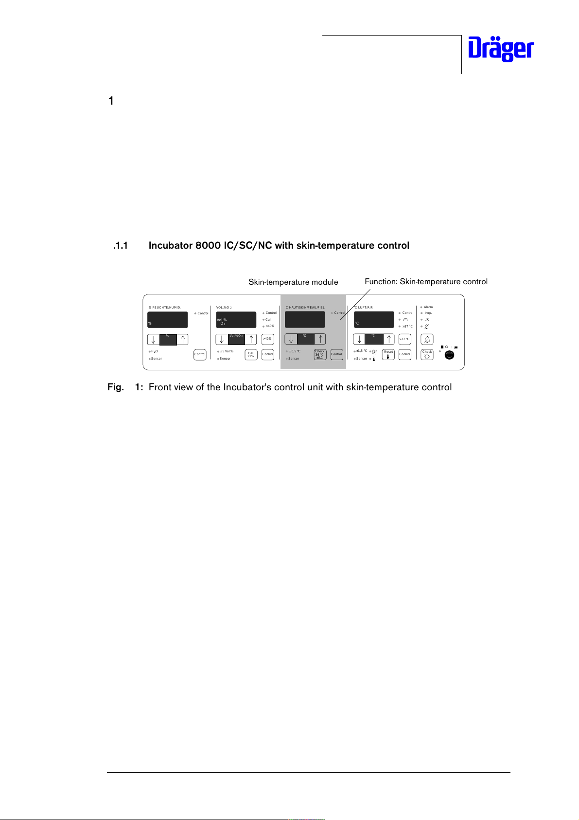
1.1.1 Incubator 8000 IC/SC/NC with skin-temperature control
Function: Skin-temperature control
>37 °C
Control
Control
>37 ˚C
Check
Alarm
Inop.
°C LUFT/AIR
°C
±1,5 °C
Sensor
°C
Reset
% FEUCHTE/HUMID.
%
%
H O
2
Sensor
Control
Control
VOL.%O
Vol.%
O
± 5 Vol.%
Sensor
Skin-temperature module
2
2
Vol.%O
Control
Cal.
>40%
2
>40%
Cal.
Control
21%
C HAUT/SKIN/PEAU/PIEL
°C
°C
± 0,5 °C
Check
36 °C
Sensor
Control
Control
±0,1
Fig. 1: Front view of the Incubator's control unit with skin-temperature control
U-Inkubator8000IC-SC-NC.fm 17.08.00
For internal use only. Copyright reserved.
6141.2XX Incubator 8000IC/SC/NC11/2000 Conversion Instructions Page 1 of 17
Page 10
Dräger Medizintechnik
1.2 Conversion Procedure
1. Move electrical height adjustment (optional) of the Incubator 8000 IC/SC/NC to the
highest position.
2. Switch off the Incubator 8000 IC/SC/NC using the ON/OFF switch.
3. Unplug the power plug of the Incubator 8000 IC/SC/NC from the mains socket-outlet.
Electrostatic discharge may damage electrostatic sensitive devices.
When handling electrostatic sensitive devices, use a static-dissipative
mat and a static dissipative wrist strap.
4. Observe ESD precautions.
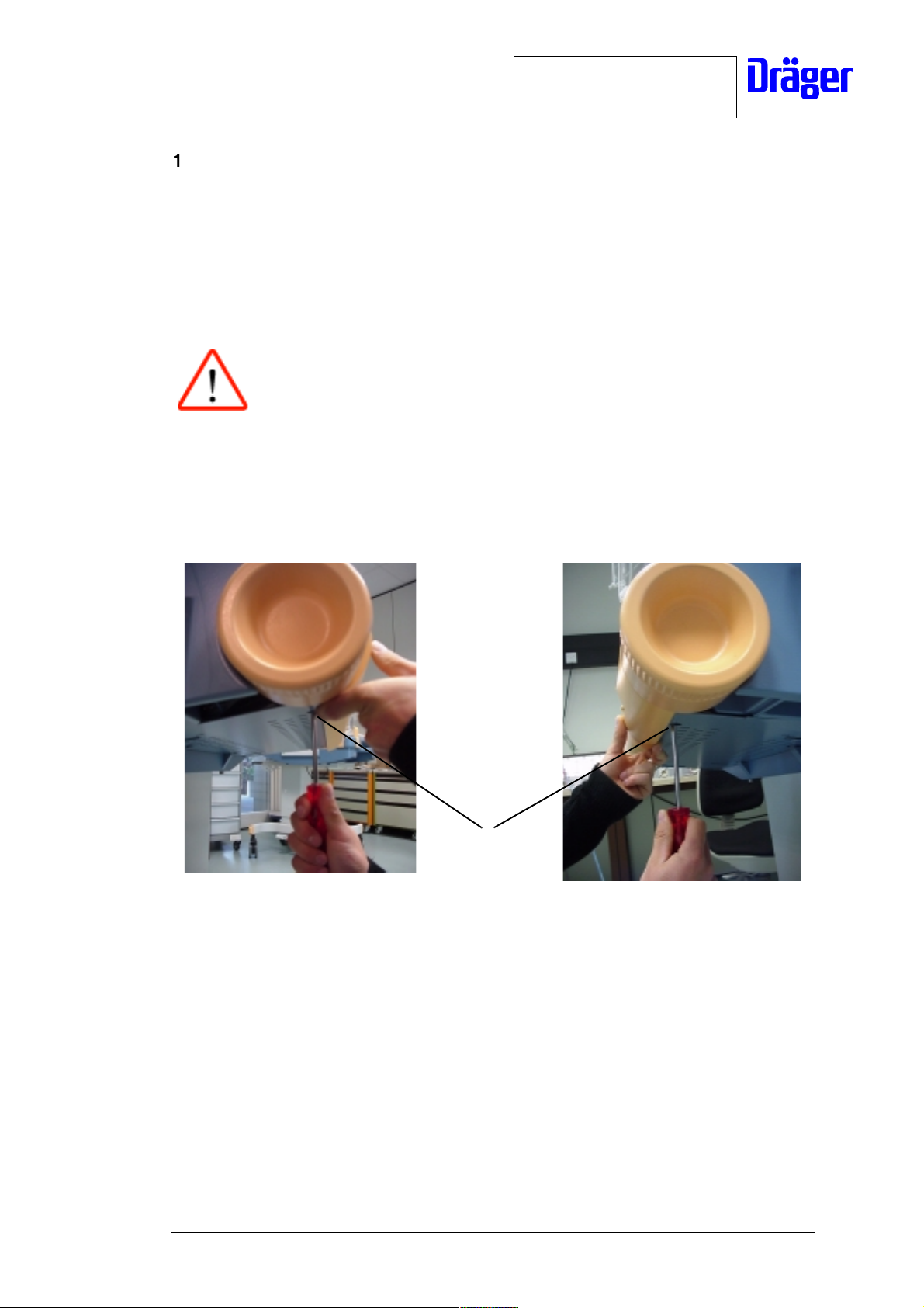
5. Support the Incubator's cover plate with one hand and turn catches (a) 90° counterclockwise.
U-Inkubator8000IC-SC-NC.fm 17.08.00
a
Fig. 3: Left and right side view of the Incubator 8000 IC/SC/NC
For internal use only. Copyright reserved.
6141.2XX Incubator 8000IC/SC/NC11/2000 Conversion Instructions Page 2 of 17
Page 11
Dräger Medizintechnik
6. Unlock latches (b) of the electronic module and fold down the electronic unit.
Inkubator 8000
D
b
b
Fig. 4: View of the Incubator 8000 IC/SC/NC
Risk of damage to equipment. The electronic unit is connected with the
Incubator's cables which might be damaged during disassembly. To
avoid damage to these cables, carefully remove the electronic unit as
shown in the following step.
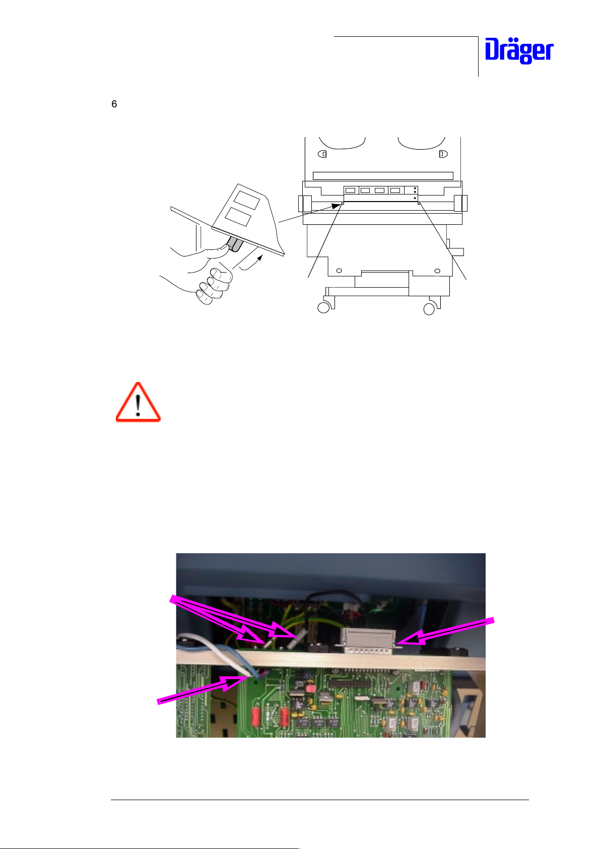
7. Remove the following cable connectors from the electronic unit:
- Disconnect cable connectors of the protective conductors (c) from the housing frame
of the electronic unit.
- Take the cable connector (d) by the connector and disconnect it from the Analog PCB.
- Take the cable connector (e), if present, by the connector and disconnect it from the
Analog PCB.
U-Inkubator8000IC-SC-NC.fm 17.08.00
c
d
e
Fig. 5: Cable connections of the electronic unit
For internal use only. Copyright reserved.
6141.2XX Incubator 8000IC/SC/NC11/2000 Conversion Instructions Page 3 of 17
Page 12
Dräger Medizintechnik
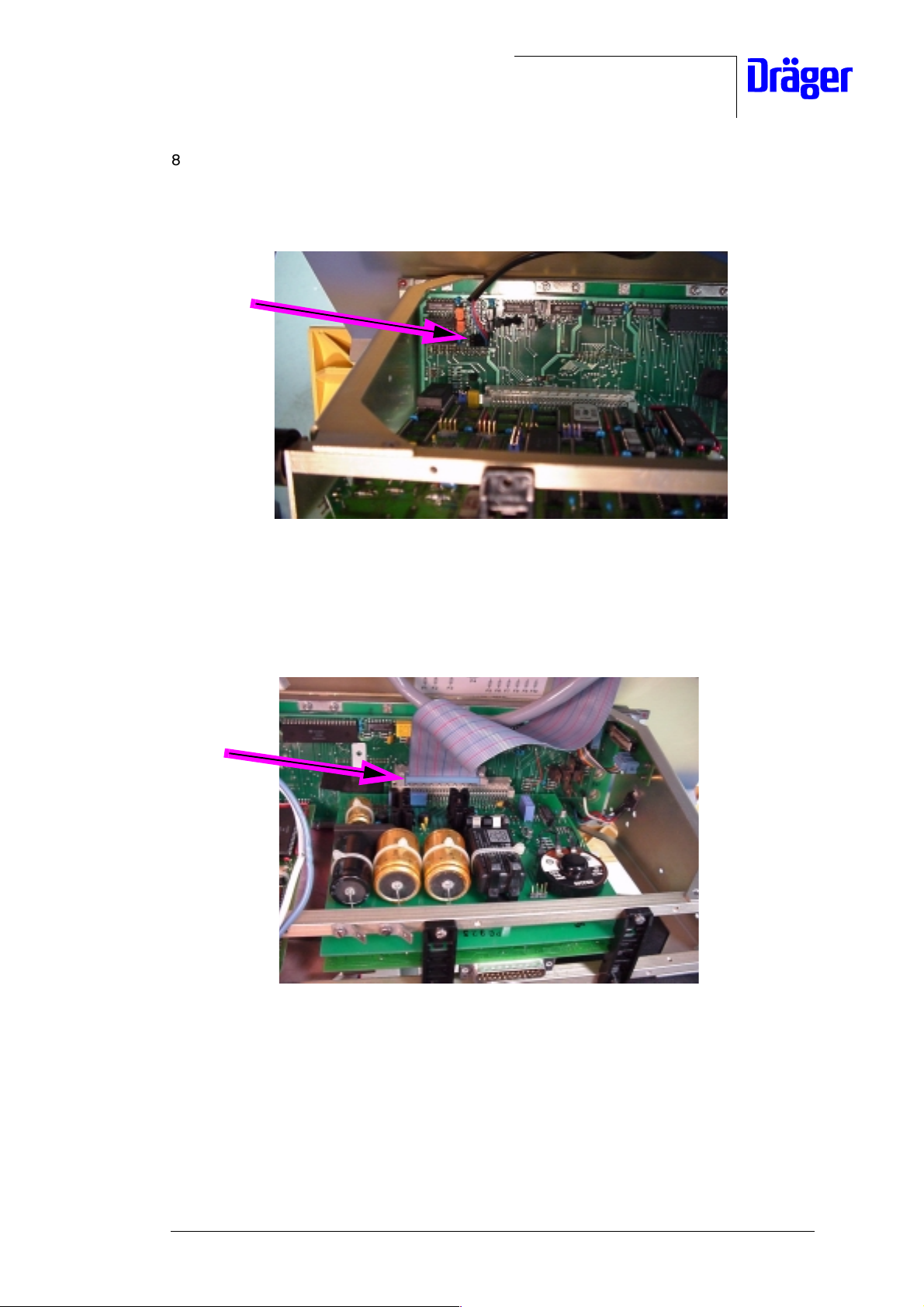
8. Carefully remove the electronic unit and disconnect the cable connector of the auxiliary
fan (f) (Note: The cable connector of the auxiliary fan is located on the left side of the
Motherboard PCB).
f
Fig. 6: Detail of the Motherboard PCB
9. Disconnect cable connector (g) from the Motherboard PCB; to do so press both latches
of the cable connectors sideways at the same time.
g
U-Inkubator8000IC-SC-NC.fm 17.08.00
Fig. 7: Right side view of the electronic unit
10. Place the electronic unit on a stable surface.
For internal use only. Copyright reserved.
6141.2XX Incubator 8000IC/SC/NC11/2000 Conversion Instructions Page 4 of 17
Page 13
Dräger Medizintechnik
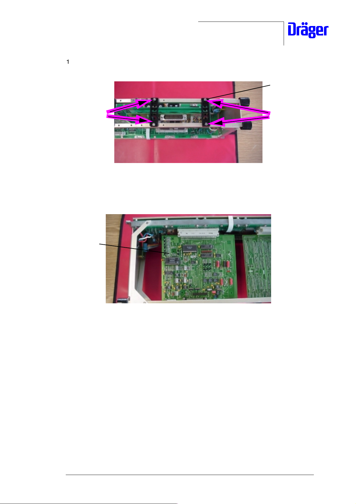
11. Unscrew screws (h) and remove board securing clamps.
Board securing
clamps
h
Fig. 8: Removing the board securing clamps
12. Pull the Analog PCB out of the Motherboard PCB.
Analog PCB
h
U-Inkubator8000IC-SC-NC.fm 17.08.00
Fig. 9: Removing the Analog PCB
13. Place the Analog PCB aside.
14. Take the modified Analog PCB from the conversion kit.
For internal use only. Copyright reserved.
6141.2XX Incubator 8000IC/SC/NC11/2000 Conversion Instructions Page 5 of 17
Page 14
Dräger Medizintechnik
Skin-temperature
control with a single
yellow socket
2M22404-00, or 2M22400-00, or 2M22404-00, or
2M22405-00, or 2M22401-00, or 2M22405-00, or
2M22406-00, or 2M22402-00, or 2M22406-00, or
2M22407-00, or 2M22403-00, or 2M22407-00, or
2M22382 2M22381 2M22382
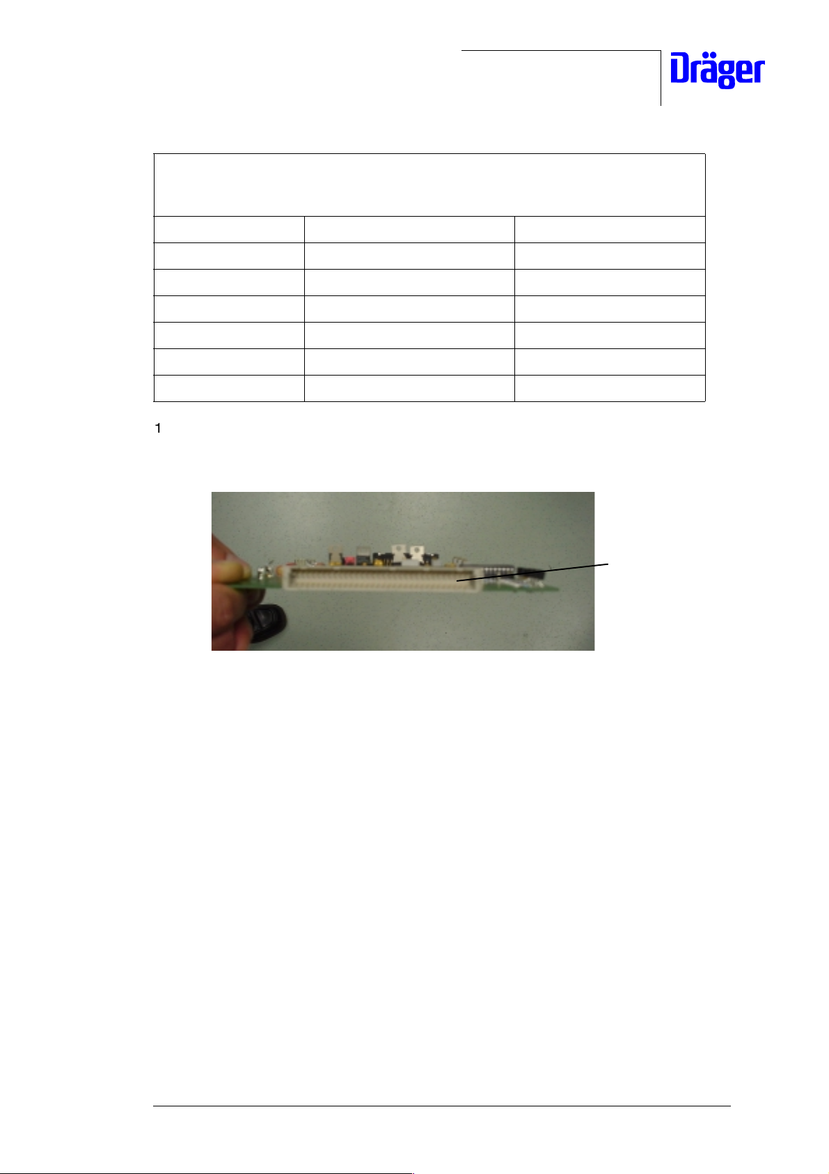
15.Check that the connecting pins of the AnalogPCB terminal strip are straight; if
necessary, carefully straighten out the connecting pins.
Skin-temperature control
(Socket: on environmental
sensor or on rear panel
Thermomonitoring
Connecting pins of
the board terminal
strip
Fig. 10: View of the Analog PCB terminal strip
U-Inkubator8000IC-SC-NC.fm 17.08.00
For internal use only. Copyright reserved.
6141.2XX Incubator 8000IC/SC/NC11/2000 Conversion Instructions Page 6 of 17
Page 15

Dräger Medizintechnik
16. Mount the modified Analog PCB on the electronic unit by pushing the Analog PCB into
the slot of the Motherboard PCB.
Modified
Analog PCB
Fig. 11: Mounting the modified Analog PCB
17. Place the board securing clamps (the guides pointing downwards) onto the frame of the
electronic unit such that the boards are secured in the guides of the board securing
clamps.
18. Secure the board securing clamps to the frame of the electronic unit using the screws
(i).
i
i
Board
securing
clamps
U-Inkubator8000IC-SC-NC.fm 17.08.00
Fig. 12: Securing the board securing clamps to the frame of the electronic unit
For internal use only. Copyright reserved.
6141.2XX Incubator 8000IC/SC/NC11/2000 Conversion Instructions Page 7 of 17
Page 16

Dräger Medizintechnik
19. Check the software version of the EPROM located on the CPU PCB (Note: The
software version is printed on the adhesive label).
20. If the installed software version is lower than those shown in the table below, take the
respective EPROM from the conversion kit and install it on the CPU PCB (Note: Make
sure the fitting position of the EPROM is correct, see the following Figure).
Adhesive label on the
EPROM
Fig. 13: EPROM
Software version to be installed
10.05 11.02
20.04 21.02
Examples:
Replace software versions 10.00 through 10.04 with software version
10.05.
Replace software version 21.00 or 21.01 with software version 21.02.
Replace software version 11.00 or 11.01 with software version 11.02.
Replace software version 21.00 or 21.01 with software version 21.02.
21. You do not need to replace the EPROM if the correct software version with the correct
revision number is installed on the CPU PCB. Assemble the Incubator, see steps 31.
22. If the existing software version on the CPU PCB has an earlier software revision
number, replace the software version of the EPROM. Then proceed as follows:
U-Inkubator8000IC-SC-NC.fm 17.08.00
For internal use only. Copyright reserved.
6141.2XX Incubator 8000IC/SC/NC11/2000 Conversion Instructions Page 8 of 17
Page 17

Dräger Medizintechnik
23. Remove screws (k) and place board securing clamps aside.
Board securing
clamps
k
h
Fig. 14: Removing the board securing clamps
24. Carefully pull the CPU PCB out of the Motherboard PCB.
CPU PCB
k
U-Inkubator8000IC-SC-NC.fm 17.08.00
Fig. 15: Removing the CPU PCB
For internal use only. Copyright reserved.
6141.2XX Incubator 8000IC/SC/NC11/2000 Conversion Instructions Page 9 of 17
Page 18

Dräger Medizintechnik
25. Remove the EPROM from its socket (preferably with an IC assembly clip) and place the
EPROM aside.
IC assembly clip
Fig. 16: Removing the EPROM from the CPU PCB.
Risk of malfunction. The Incubator will malfunction if the EPROM is
mounted incorrectly. To avoid malfunctions, make sure the EPROM is
fitted correctly into the IC socket, see the following Figure.
26. Take the necessary EPROM from the conversion kit (see the following table) and fit the
EPROM correctly into the respective socket (preferably by using an IC assembly clip).
EPROM
U-Inkubator8000IC-SC-NC.fm 17.08.00
Fig. 17: EPROM on the CPU PCB; fitting position of the EPROM
For internal use only. Copyright reserved.
6141.2XX Incubator 8000IC/SC/NC11/2000 Conversion Instructions Page 10 of 17
Page 19

Dräger Medizintechnik
Software version to be installed
10.05 11.02
20.04 21.02
27. Check that the connecting pins of the CPU PCB terminal strip are straight; if necessary,
carefully straighten out the connecting pins.
Connecting pins of the
board terminal strip
Fig. 18: Checking the connecting pins
28. Mount the CPU PCB on the electronic unit by pushing the CPU PCB into the slot of the
Motherboard PCB.
CPU PCB
Fig. 19: Mounting the CPU PCB
U-Inkubator8000IC-SC-NC.fm 17.08.00
For internal use only. Copyright reserved.
6141.2XX Incubator 8000IC/SC/NC11/2000 Conversion Instructions Page 11 of 17
Page 20

Dräger Medizintechnik
29. Place the board securing clamps (the guides pointing downwards) onto the frame of the
electronic unit such that the boards are secured in the guides of the board securing
clamps, see the following Figure.
30. Secure the board securing clamps to the frame of the electronic unit using the screws
(l).
l
Fig. 20: Securing the board securing clamps to the frame of the electronic unit
31. Place the electronic unit in front of the Incubator and connect the auxiliary fan connector
(m) from the cooling fan in the blue Incubator housing to the connection of the
Motherboard PCB (Note: The connection is located on the left side of the
Motherboard PCB).
m
l
U-Inkubator8000IC-SC-NC.fm 17.08.00
Fig. 21: Auxiliary fan connector
For internal use only. Copyright reserved.
6141.2XX Incubator 8000IC/SC/NC11/2000 Conversion Instructions Page 12 of 17
Page 21

Dräger Medizintechnik
32. Push the cable connector (n) onto the connection of the Motherboard PCB until both
latches engage.
n
Fig. 22: View of the electronic unit
33. Fit the electronic unit into the Incubator by suspending the electronic unit on the guides
of the Incubator, see the following Figure.
Guides of the
Incubator
Fig. 23: Fitting the electronic unit
U-Inkubator8000IC-SC-NC.fm 17.08.00
For internal use only. Copyright reserved.
6141.2XX Incubator 8000IC/SC/NC11/2000 Conversion Instructions Page 13 of 17
Page 22

Dräger Medizintechnik
34. Connect cable terminals (o) of the protective conductors to the cable connectors on the
housing frame of the electronic unit.
o
Fig. 24: Detail of the housing frame of the electronic unit
Risk of damage to equipment. The connecting cable of the skintemperature sensors might be squeezed if installed incorrectly inside
the Incubator. To avoid squeezing of the connecting cable of the skintemperature sensor, install the connecting cable as shown in the
following Figure.
35. Connect cable connector (p), if fitted, to the Analog PCB (pay attention to the coding).
Only on units with a yellow skin-temperature socket fitted on the left side of
the blue housing of the Incubator.
U-Inkubator8000IC-SC-NC.fm 17.08.00
For internal use only. Copyright reserved.
6141.2XX Incubator 8000IC/SC/NC11/2000 Conversion Instructions Page 14 of 17
Page 23

Dräger Medizintechnik
p
Detail of the coded cable
Fig. 25: Mounting the cable connector; coding of the cable connector
36. Connect the sub D connector to the Analog PCB.
connector
Fig. 26: Analog PCB
Sub D connector
U-Inkubator8000IC-SC-NC.fm 17.08.00
For internal use only. Copyright reserved.
6141.2XX Incubator 8000IC/SC/NC11/2000 Conversion Instructions Page 15 of 17
Page 24

Dräger Medizintechnik
37. Make sure no cable is squeezed, then fold up the electronic unit and secure it to the
Incubator using the latches (q).
Inkubator 8000
D
q
q
Fig. 27: Mounting the electronic unit
38. Fold up the Incubator's cover plate and secure it to the Incubator by turning the catches
(q) 90° clockwise.
U-Inkubator8000IC-SC-NC.fm 17.08.00
q
Fig. 28: Left and right side view of the Incubator 8000 IC/SC/NC
39. Check the electrical safety of the Incubator 8000 IC/SC/NC according to the Test
Certificate or Test List or, for the USA and Canada, according to CAN/CSA - 22.2 No.
601.1 - M90.
40. Plug the power plug of the Incubator 8000 IC/SC/NC into the mains socket-outlet.
For internal use only. Copyright reserved.
6141.2XX Incubator 8000IC/SC/NC11/2000 Conversion Instructions Page 16 of 17
Page 25

Dräger Medizintechnik
41. Switch on the Incubator 8000 IC/SC/NC using the ON/OFF switch.
The Incubator 8000 IC/SC/NC carries out a self test and should not display any error
message on the 7-segment-display.
42. To check the Incubator 8000 IC/SC/NC, see the "Checking readiness for operation"
section in the respective Instructions for Use/Operating Instructions.
43. Switch off the Incubator 8000 IC/SC/NC using the ON/OFF switch.
44. Take the adhesive label (2M22384) from the conversion kit and attach to the control unit
as shown in the Figure below.
Adhesive label
>37 °C
Control
Control
>37 ˚C
Alarm
Check
Inop.
% FEUCHTE/HUMID.
%
%
H O
2
Sensor
Control
Control
VOL.%O
Vol.%
O
± 5 Vol.%
Sensor
Control
Control
°C LUFT/AIR
°C
±1,5 °C
Sensor
°C
Reset
>40%
Control
Control
Cal.
>40%
C HAUT/SKIN/PEAU/PIEL
°C
°C
± 0,5 °C
Check
36 °C
Sensor
±0,1
2
2
Vol.%O
2
Cal.
21%
Fig. 29: Front view of the control unit
45. Place the dismounted Analog PCB in a shock-protected and electrostatic discharge
protected package (if applicable, pack the EPROM separately from the Analog PCB).
46. Fill out the reply/feedback form and return it together with the dismounted Analog PCB
and the EPROM to the sender stated in the head of the reply form.
Re-use bag and packing of dismounted components adequately.
U-Inkubator8000IC-SC-NC.fm 17.08.00
47. Place Incubator 8000 IC/SC/NC to the owner's disposal.
For internal use only. Copyright reserved.
6141.2XX Incubator 8000IC/SC/NC11/2000 Conversion Instructions Page 17 of 17
Page 26

Page 27

Dräger Medical, Inc.
Follow up Technical Service Bulletin # 12
Product: Incubator 8000 IC / SC / NC
Date: November 30, 1999
Re: Follow up validation of replacement of CPU PCB Incubator
82 90 571 - 00
Reference Doc: Technical Bulletin TB#004-96, dated July 15, 1996
Reason: Improved reliability with CPU Incubator PCB P/N 82 90 571 as of
revision number 01.0 or higher.
Solution: All CPU PCBs 82 90 571 with revision number 00 must be replaced
by CPU PCBs 82 90 571 with revision number 01.0 or higher.
Devices affected:All Incubators 8000 SC, IC, and NC with the following serial
numbers: ARFA - 0001 (January 1993) to ARJB - 9999 (February
1995).
or
Incubators 8000 SC, IC, NC which have been repaired with the CPU
Incubator PCB 82 90 571 - 00 since January 1993.
When: At next Service Call or Preventive Maintenance. This action was to
be completed by October 31, 1996. Please verify that all units have
been corrected.
Reporting: To Dräger Medical, Inc. by Fax (215) 723 - 5935 by the end of
October 31, 2000.
Additional Info: The following CPU PCBs can be used in the Incubator 8000 series:
• CPU Incubator PCB P/N 82 90 571 with revision number 01.0 or
higher.
or
• CPU Standard 2 PCB P/N 83 05 141
6141.22X Incubator 8000 IC / SC/ NC TSB No. 12 November 1999 1/2
Page 28

Dräger Medical, Inc.
Identification: In order to identify the type of board installed it is
necessary to open the plate underneath the electronics module. The
boards are identified by a label on the 64 pin plug connector of the
CPU PCB (order no., revision number, and serial number). Unlike
boards with 00 revision numbers, the 82 90 571 boards with revision
number 01.0 or higher have a small additional board (28.6 mm x
28.6 mm or 1.1 inch x 1.1 inch) with a quartz and an IC.
Cost: Parts free of charge
Ordering Info: CPU Incubator PCB 82 90 571
Distribution: Dräger Service Personnel and Authorized Service Organizations for
NCS products.
If you have any questions, please contact Technical Support by
phone at 1-800-543-5047 or by fax at 1-215-723-5935
Dräger Medical, Inc.
Technical Product Manager
Andreas Lenke
6141.22X Incubator 8000 IC / SC/ NC TSB No. 12 November 1999 2/2
Page 29

Dräger Medical, Inc.
Technical Service Bulletin # 17
Product: Incubator 8000 IC / SC / NC
Date: November 30, 1999
Re: Noise produced by the auxiliary fan on the PCB Power Pack
Reference Doc: IDM no. 21 / 07.98
Reason: Occasionally the auxiliary fan on the PCB Power Pack (82 90 461)
produces too much noise.
Solution: Cut the cable connecting the auxiliary fan and the PCB at both ends,
thus physically removing the connection completely. The
disconnection of the auxiliary fan on the PCB Power Pack produces
no relevant safety risks.
Devices affected: Incubator 8000 series shipped prior to July 1998 with a
Power Pack PCB with an auxiliary fan.
When: At next Service Call or Preventive Maintenance
Additional Info: N/A
Cost: N/A
Ordering Info: N/A
Distribution: Dräger Service Personnel and Authorized Service Organizations for
NCS products.
If you have any questions, please contact Technical Support by
phone at 1-800-543-5047 or by fax at 1-215-723-5935
Dräger Medical, Inc.
Technical Product Manager
Andreas Lenke
6141.22X Incubator 8000 IC / SC/ NC TSB No. 17 November 1999 1/1
Page 30

Page 31

Dräger Medical, Inc.
Incubator 8000 IC / SC / NC
Technical Service Bulletin # 19
Re: Retrofitting of warning labels
Update: May 31, 2000
Reference Doc: Complaint # 980046
Reason: Patient Safety and Incubator Performance may be seriously
compromised if air flow passages are not kept clear of obstruction
(blankets, surgical drapes, stuffed animals, etc.) during clinical use.
Additionally, when the access panel is open, a curtain of warm air
flows along the front of the mattress towards the top of the hood.
Because the temperature of this air curtain is higher than the typical
incubator air temperature, the infant and all its extremities must be
kept clear of this warm air path.
Solution: The following warning shall be added to the Operating Instructions
and labeling of the Incubator 8000 IC, Incubator 8000 SC, and
Incubator 8000 NC:
1. The letter "Important Information for Users of Dräger Incubator
8000 IC/SC/NC" is to be filed in the Operating Instructions of
each unit.
2. A warning label is to be placed on the front and on the back face
of the mattress stretcher according to the following Instruction
"Adhesive Statement 2M22363".
6141.22X Incubator 8000 IC / SC/ NC TSB No. 19 May 2000 1/2
Page 32

Dräger Medical, Inc.
Devices affected: All units in the USA and Canada delivered prior May 2000.
When: At next Service Call or Preventive Maintenance.
Additional Info: As always, it is essential that the Customers train each potential user so
that all are adept in properly and safely using the incubator.
Cost: Labels free of charge.
Ordering Info: For one Incubator order 2 pieces:
Warning label Incubator P/N 2M 22 351
Distribution: Dräger Service Personnel and Authorized Service Organizations for
CCS products.
If you have any questions, please contact Technical Support by
phone at 1-800-543-5047 or by fax at 1-215-721-5789
Dräger Medical, Inc.
Technical Product Manager
6141.22X Incubator 8000 IC / SC/ NC TSB No. 19 May 2000 2/2
Page 33

Page 34

Page 35

Dräger Medical, Inc.
Incubator 8000 IC / SC / NC
Electrical Safety Test in the USA and Canada according to
CAN/CSA - 22.2 No. 601.1 - M90
1 Visual inspection of basic unit
• Power cord
• Compare fuses to stated ratings on the backside of the Incubator next to the inlet of
the power cord.
2 Safety testing Incubator 8000 IC / SC / NC with Biotek Model 501
• Fold down flap below electronics module after undoing the two locks.
• Warning: These tests can expose personnel to hazardous electric shock and must
be carried out with caution.
• Note: Do not plug the Biotek 501 Pro safety analyzer power cord into a line
isolation monitor as inaccurate readings may occur.
• Plug the Biotek 501 Pro power cord into a live AC receptacle, place the power
switch of the Biotek 501 Pro to the "1" or ON position and ensure that the keys
marked "GROUND", "NEUTRAL" and "POLARITY" are in the NORMAL position.
• Note: If the corresponding red LEDs for Ground, Neutral, and Polarity are not lit,
they are in the normal position.
2.1 Chassis Resistance Testing
• Attach the ground lead from the red "Test lead" input to the ground hole of the AC
test receptacle on the Biotek 501 Pro. Select the "Single lead" condition by
ensuring that the "SINGLE/DUAL" key is not illuminated. Press the gray key
marked "RESIST", then press the blue key marked "CAL". When the word CAL is
no longer shown in the display window of the Biotek 501 Pro, you may proceed.
• Remove the red lead from the ground hole of the AC test receptacle and attach the
alligator clip to the free end, leaving the other end plugged into the red "Test lead"
Incubator 8000 IC/SC/NC Electrical Safety Test with Biotek Model 501 August 2000 Page 1 of 6
Page 36

Dräger Medical, Inc.
input of the Biotek 501 Pro with the "Single Lead" and "Resistance" conditions still
selected.
• Plug the Incubator power cord into the test receptacle of the Biotek 501 Pro.
• Perform 4 tests with the alligator clip attached to the following test items of the
Incubator:
1) Screw at the base plate of electrical
height adjustment (if available)
3) Earth chassis connection of the flap
below electronics module
2) Screw at the metal base plate below
Incubator housing
4) Electronics module, earth chassis
connection
• The resistance reading then shown on the Biotek 501 Pro is the "Chassis
Resistance". Bend and exercise the power cord to check for intermittent reading.
• Maximum allowable test values:
Chassis Resistance 0.2 Ohm
Incubator 8000 IC/SC/NC Electrical Safety Test with Biotek Model 501 August 2000 Page 2 of 6
Page 37

Dräger Medical, Inc.
• Afterwards leave alligator clip at test item 4) or attach the alligator clip to the test
item with the lowest resistance.
2.2 Enclosure Leakage Current (Chassis Leakage Testing)
• Press the gray "LEAKAGE" key, leaving all other selections from the previous test
the same.
• Switch on Incubator and allow the unit to complete the self-test.
• Switch on humidity module.
• Set air temperature and humidity higher than measured values.
• Set up the Biotek 501 Pro for the following tests by using the white keys labeled
"Ground", "Neutral" and "Polarity".
• Note: If the corresponding red LEDs for Ground, Neutral, and Polarity are not lit,
they are in the normal position.
• This is a measurement of the leakage current from the Chassis to earth ground.
• Activate height adjustment (if available) during the following tests.
• Maximum allowable test values under Normal Condition:
Normal Ground, Normal Polarity, Normal Neutral: 100 µA
Normal Ground, Reverse Polarity, Normal Neutral: 100 µA
(According to CAN/CSA - 22.2 No. 601.1 - M90, Sub-clause 19.3, Table IV)
• Maximum allowable test values under Single Fault Condition:
Open Ground, Normal Polarity, Normal Neutral: 500 µA, but not 0 µA
Open Ground, Reverse Polarity, Normal Neutral: 500 µA, but not 0 µA
(According to CAN/CSA - 22.2 No. 601.1 - M90, Sub-clause 19.3, Table IV)
Incubator 8000 IC/SC/NC Electrical Safety Test with Biotek Model 501 August 2000 Page 3 of 6
Page 38

Dräger Medical, Inc.
2.3 Earth Leakage Current (Ground Wire Leakage Testing)
• Remove the red lead with the alligator clip from the Incubator.
• Remove the alligator clip from the red test lead and plug this end into the green
input jack "GROUND" on the back panel on the Biotek 501 Pro.
• Leave all other selections from the previous test the same.
• The Incubator is still switched on.
• Set up the Biotek 501 Pro for the following tests by using the white keys labeled
"Ground", "Neutral" and "Polarity".
• Note: If the corresponding red LEDs for Ground, Neutral, and Polarity are not lit,
they are in the normal position.
• This is a measurement of the leakage current flowing through the ground wire of
the power cord.
• Activate height adjustment (if available) during every following test.
• Maximum allowable test values under Normal Condition:
Open Ground, Normal Polarity, Normal Neutral: 500 µA, but not 0 µA
Open Ground, Reverse Polarity, Normal Neutral: 500 µA, but not 0 µA
(According to CAN/CSA - 22.2 No. 601.1 - M90, Sub-clause 19.3, Table IV)
• Maximum allowable test values under Single Fault Condition:
Open Ground, Normal Polarity, Open Neutral: 1000 µA
Open Ground, Reverse Polarity, Open Neutral: 1000 µA
(According to CAN/CSA - 22.2 No. 601.1 - M90, Sub-clause 19.3, Table IV)
• Switch off Incubator.
Incubator 8000 IC/SC/NC Electrical Safety Test with Biotek Model 501 August 2000 Page 4 of 6
Page 39

Dräger Medical, Inc.
2.4 Patient leakage current from the skin temperature connection to earth
• Remove the test lead from the Biotek 501 Pro and leave all other selections from
the previous test the same.
• Units with one or two skin temperature connections on the left side of Incubator
housing:
Short all pins of the two skin temperature connectors using a shorting plug
79 10 484. Plug the other end into the input jack "RA" of the Biotek 501 Pro.
• Units without ThermoMonitoring:
Short all pins of the skin temperature connector by using the
a) Skin Temperature Sensor Simulator 79 01 236 with the switch in "R
position. Short the two yellow "R
"R
to the input jack "RA" of the Biotek 501 Pro.
EXT"
outlets from the simulator and connect
EXT"
EXT
"
or
b) Use Adapter 2M 20 736 and short a sensor connector as a test lead to the
safety tester. Plug the other end into the input jack "RA" of the Biotek 501 Pro.
• Select the "ECG LEAK" key on the Biotek 501 Pro.
• Use the Increment or Decrement arrow on the Biotek 501 Pro to select the "RA-
Gnd" option.
• Set up the Biotek 501 Pro for the following tests by using the white keys labeled
"Ground", "Neutral" and "Polarity".
• Switch on Incubator.
• Maximum allowable test values under Normal Condition:
Normal Ground, Normal Polarity, Normal Neutral: 100 µA
Normal Ground, Reverse Polarity, Normal Neural: 100 µA
(According to CAN/CSA - 22.2 No. 601.1 - M90, Sub-clause 19.3, Table IV)
Incubator 8000 IC/SC/NC Electrical Safety Test with Biotek Model 501 August 2000 Page 5 of 6
Page 40

Dräger Medical, Inc.
• Maximum allowable test values under Single Fault Condition:
Open Ground, Normal Polarity, Normal Neutral: 500 µA
Open Ground, Reverse Polarity, Normal Neural: 500 µA
(According to CAN/CSA - 22.2 No. 601.1 - M90, Sub-clause 19.3, Table IV)
• Switch off Incubator and disconnect power cord from the Biotek 501 Pro and
remove the test equipment
• Close flap below electronics module.
Incubator 8000 IC/SC/NC Electrical Safety Test with Biotek Model 501 August 2000 Page 6 of 6
Page 41

Page 42

DrägerService is a
division of Draeger Medical, Inc.
3122 Commerce Drive
Telford, PA 18969
Tel: (215) 721-5402
(800) 543-5047
Fax:(215) 723-5935
Web: www.draegermedical.com
Printed in the U.S.A.
 Loading...