


Technical Service Manual
Gamma / Gamma XL Patient Monitors
Monitor System
Emergency Care • OR/ Anesthesia • Critical Care • Perinatal Care • Home Care
Revision 0
6013.053
MS14879
Because you care

Copyright by Dräger Medical AG & Co. KGaA, Lübeck, Germany.
No reproduction allowed for commercial purposes.
Read and understand the Instructions for Use/Operator’s Manual.
This Technical Documentation does not replace the Instructions for Use/Operator’s
Manual.
The warranty and liability conditions of the general terms and conditions for business
transactions of Dräger Medical AG & Co. KGaA are not extended by this Technical
Documentation.
Observe all applicable technical laws and regulations.
Insofar as reference is made to laws, regulations or standards, these are based on the
legal system of the Federal Republic of Germany. Observe the laws and regulations
applicable in your country.

Contents
General
1 Advisory 3
2 Important information 3
2.1 Symbols and Definitions ......................................................................................................... 3
3 Introduction 4
3.1 Service Strategy ..................................................................................................................... 4
4 Product Overview 5
4.1 Monitored Patient Parameters ................................................................................................ 5
4.2 Gamma/Gamma XL Monitor Controls .................................................................................... 5
4.3 TFT-LCD Display .................................................................................................................... 5
4.4 Alarms .................................................................................................................................... 5
4.5 Monitor/Software Tracking ......................................................................................................6
5 Technical Data 6
5.1 General ................................................................................................................................... 6
5.2 Environmental ........................................................................................................................ 6
5.3 Display .................................................................................................................................... 7
5.4 Outputs ................................................................................................................................... 8
5.5 Connectors ............................................................................................................................. 8
6 Monitor Controls 9
6.1 Main Screen Key .................................................................................................................... 9
6.2 Menu Key ............................................................................................................................... 9
6.3 Alarm Limits Key .................................................................................................................. 10
6.4 Alarm Silence Key ................................................................................................................ 10
6.5 All Alarms Off Key ................................................................................................................ 10
6.6 NBP Start/Stop Key .............................................................................................................. 10
6.7 Fast Access Key ................................................................................................................... 10
6.8 Record Key ........................................................................................................................... 10
All rights reserved. Copyright reserved.
K6013053IECIVZ.fm 03.12.04
Dräger Medical AG & Co. KGaA Contents
I

Contents
Function Description
1 Overview 15
2 Parameter Inputs 15
3 Main PC Board 15
3.1 LCD Control ..........................................................................................................................16
3.2 Network Interface ................................................................................................................. 16
3.3 Front Panel Circuitry .............................................................................................................16
3.4 Pod Interface ........................................................................................................................ 16
3.5 Battery Control and ON/OFF Control ...................................................................................16
3.6 BOOT Process, Flash Memory, and DRAM .........................................................................16
3.7 SRAM ................................................................................................................................... 17
3.8 68HC912D60A Microcontroller .............................................................................................17
4 Front End 17
4.1 NBP Control ..........................................................................................................................17
4.2 Safety ................................................................................................................................... 17
5 Physiological Parameter Data Acquisition 18
5.1 ECG/Resp ............................................................................................................................ 18
5.2 Respiration ........................................................................................................................... 20
5.3 SpO2 .....................................................................................................................................21
5.4 Invasive Blood Pressure .......................................................................................................23
5.5 Non-Invasive Blood Pressure ...............................................................................................24
5.6 Temperature Circuit .............................................................................................................. 27
6 etCO2 Pod 28
7 Power Supply System 29
7.1 Main Battery ......................................................................................................................... 29
7.2 AC Power Adapter ................................................................................................................30
II
Dräger Medical AG & Co. KGaA Contents
All rights reserved. Copyright reserved.
K6013053IECIVZ.fm 03.12.04

Contents
Maintenance Procedures
1 Maintenance Procedure 33
1.1 General ................................................................................................................................. 33
1.2 Battery .................................................................................................................................. 33
1.3 Replacing NBP Air Intake Filter ............................................................................................ 33
1.4 Safety and Function Tests .................................................................................................... 34
1.5 Acceptance Test Report ....................................................................................................... 45
Schematics and Diagrams
1 IBP Connector 49
2 MultiMed Pod Connector 49
3 Docking Station Connector 50
4 Alarm Cable (Unterminated) 50
5 Interface Plate Connector 51
6 Recorder/Alarm Y-cable 51
7 Infinity Docking Station Connectors 52
8 PodPort Connector Pins 53
Fault-Cause-Remedy
1 Troubleshooting 57
1.1 Power Problems ................................................................................................................... 57
1.2 Optical Encoder Malfunction ................................................................................................ 59
1.3 TFT-LCD Display Malfunction .............................................................................................. 59
All rights reserved. Copyright reserved.
K6013053IECIVZ.fm 03.12.04
1.4 Fixed Key Fails to Function .................................................................................................. 60
Dräger Medical AG & Co. KGaA Contents
III

Contents
1.5 Visual or Audible Alarm Reporting Failure ............................................................................ 60
1.6 NBP Malfunction ...................................................................................................................60
1.7 etCO2 Malfunction ................................................................................................................61
1.8 No Printout from Recorder ....................................................................................................62
1.9 Isolating Cable Malfunctions .................................................................................................63
1.10 Patient-Related Data Not Retained or Monitor Fails to Compute Trends ............................. 63
Annex
Spare parts list
Test List
Problem Report
All rights reserved. Copyright reserved.
IV
K6013053IECIVZ.fm 03.12.04
Dräger Medical AG & Co. KGaA Contents

General
1

2
Gamma / Gamma XL Patient Monitor General
General
1 Advisory This document corresponds to the version/revision level effective at the time
of system delivery. Revisions to hardcopy documentation are not automatically distributed.
The installation and service of equipment described herein is to be performed
by qualified personnel who are employed by Dräger Medical or one of its affiliates or who are otherwise authorized by Dräger Medical or one of its affiliates to provide such services.
Assemblers and other persons who are not employed by or otherwise directly
affiliated with or authorized by Dräger Medical or one of its affiliates are
directed to contact one of the local offices of Dräger Medical or one of its affiliates before attempting installation or service procedures.
2 Important informa-
tion
This Technical Documentation/Service Manual conforms to the International
Standard IEC 60601-1.
Read each step in every procedure thoroughly before beginning any test.
Always use the proper tools and specified test equipment. If you deviate from
the instructions and/or recommendations in this Technical Documentation/
Service Manual, the equipment may operate improperly or unsafely, or the
equipment could be damaged.
The maintenance procedures described in this Technical Documentation/
Service Manual may be performed by qualified service personnel only. These
maintenance procedures do not replace inspections and servicing by Dräger
Medical.
Strictly follow the Instructions for Use/Operating Instructions! This
Technical Documentation does not replace the Instructions for
Use/Operating Instructions. Any use of the product requires full
understanding and strict observation of the product-specific Instructions for Use/Operating Instructions.
Unless otherwise stated, reference is made to laws, regulations or standards (as amended) applicable in the Federal Republic of Germany.
2.1 Symbols and Definitions
This symbol is used to provide important information that, if ignored,
could lead directly to a patient’s or operator’s injury. It is also used to
provide important information that, if ignored, could lead directly to
equipment damage and, indirectly, to a patient’s injury.
The following three alert levels are used in this documentation to indicate a
hazardous situation and how to avoid it.
All rights reserved. Copyright reserved.
Gamma_Gamma_XL_SM_General.fm 03.12.04
Dräger Medical AG & Co. KGaA 6013.053 Revision 0 Released
3
General Gamma / Gamma XL Patient Monitor
Danger Danger indicates an imminently hazardous situation
which, if not avoided, will result in death or serious
injury.
Warning Warning indicates a potentially hazardous situation
which, if not avoided, could result in death or serious
injury.
Caution Caution indicates a hazardous situation which, if not
avoided, may result in minor or moderate injury. Caution
may also be used to alert against unsafe practices.
Danger
Danger indicates an imminently hazardous situation which, if not
avoided, will result in death or serious injury.
Note
This symbol is used to provide additional information, operating tips, or
maintenance suggestions.
Definitions according to German standard DIN 31051:
Inspection = examination of actual condition
Servicing = measures to maintain specified condition
Repair = measures to restore specified condition
Maintenance = inspection, servicing, and repair
3 Introduction In keeping with the service strategy for the Infinity Gamma Patient Monitor
and the Infinity Gamma XL Patient Monitor, this technical manual provides
the necessary information required to maintain a Gamma/Gamma XL Patient
Monitor in the field. The Gamma and Gamma XL are both stationary and portable monitors designed to monitor patient vital signs (refer to user’s guide for
monitoring options). For stationary operation near a bedside, the monitor is
connected to an AC/DC power adapter or placed on a specially designed
docking station attached to a shelf, wall, or rolling stand that securely locks it
into place. While on the docking station, the monitor is powered by an IDS
power supply. When the monitor is detached from an IDS, it is powered by a
lead acid battery or by an optional Lithium ion battery. The monitor is reattached to the AC/DC Power Adapter or placed back on an IDS to recharge
the battery.
3.1 Service Strategy The monitor has been designed for high reliability, with an estimated MTBF of
50,000 hours (5.7 yrs.) of continuous operation.Therefore, the service strategy is based on few failures in the field, a clear definition of failure analysis by
field service personnel, and a quick repair turnaround. The field repair philosophy is based on the distributed and approved spare parts list.
4
This manual is intended to serve as a source of technical information, for
qualified field service personnel to use in maintaining a Gamma/Gamma XL
patient monitor in accordance with the Dräger Medical Service Strategy. Field
service is expected to be successful “First-Time Every Time.”
Dräger Medical AG & Co. KGaA 6013.053 Revision 0 Released
Gamma_Gamma_XL_SM_General.fm 03.12.04
All rights reserved. Copyright reserved.

Gamma / Gamma XL Patient Monitor General
4 Product Overview Gamma and Gamma XL Patient Monitors are light-weight, battery-equipped,
hand-held or semi-permanently mounted devices for general purpose monitoring of a preconfigured set of physiological parameters. When not connected to a hospital’s main ac power, they use a battery with approxi-mately
1¼ hours (3 hrs. for Li option battery) of operating time. A power adapter or
IDS, which also charges the battery, can be used to operate the monitor from
the hospital’s main ac power circuit.
4.1 Monitored Patient
Parameters
4.2 Gamma/Gamma XL
Monitor Controls
The Gamma/Gamma XL monitors the following physiological parameters:
• ECG (three-lead, five-lead, or six-lead pod)
• Respiration
• Pulse Oximetry (SpO2 and PLS)
• Temperature
•NBP
• IBP1, IBP2 (locked option)
• etCO2 via PodComm Port (locked option)
•Arrhythmia
• OCRG (locked option)
• Dual Lead S-T Segment Analysis (locked option)
• Anesthetic Gas Monitoring (Gamma XL only, locked option)
All functions are controlled by a 16-position rotary knob and nine front panel
fixed keys - Alarm Silence, Record, Alarm Limits, NBP Start/Stop, All Alarms
Off, Fast Access, Main Screen, Menu, and ON/OFF. Turning the rotary knob
locates different menu items, and pressing the knob in selects the item.
Depending on the item selected, pressing the knob in may either bring up
another menu or initiate an action. See Section 5 Technical Data. For detailed
operating instructions, consult the Gamma/Gamma XL Patient Monitor User
Guide applicable to the installed software.
4.3 TFT-LCD Display The Gamma Patient Monitor has a 6.5 inch (16.5cm), 3-channel (optional 4th
channel) color TFT-LCD display. The Gamma XL Patient Monitor has an 8.3
inch (21cm), 4-channel color TFT-LCD display. Waveforms display in Erase
Bar mode at 25 ±20% mm/s (except for respiration and etCO2 waveforms
which display at 6.25 ±20% mm/s). All displays for a given parameter (label,
unit of measure, and waveform) are in the same color. If a waveform is not
displayed for a parameter, its label is gray.
4.4 Alarms Alarm limits can be set either on a user-definable setup table, or automatic-
ally based on current parameter values. Three alarm grades, each with a distinct alarm tone, announce alarm situations of varying severity, as follows:
• life-threatening (asystole or ventricular fibrillation - red)
• serious (parameter limit alarms - yellow)
• advisory (technical alarms - white)
The message field background and parameter field of the parameter in alarm,
and alarm LED, are displayed in the color associated with the alarm grade as
given above.
All rights reserved. Copyright reserved.
Gamma_Gamma_XL_SM_General.fm 03.12.04
Dräger Medical AG & Co. KGaA 6013.053 Revision 0 Released
5

General Gamma / Gamma XL Patient Monitor
4.5 Monitor/Software
Tracking
Each monitor has a unique ID chip installed in its rear housing for diagnostic
and tracking purposes, and un/locking optional software features.
5 Technical Data Technical Data included in this Section is as of publication date of this Man-
ual. Changes are reported in User Guide applicable to installed SW.
5.1 General Table 1 General Specifications
Parameter Specification
Power Requirements 100-250 VAC through AC power adapter
Mains Frequency 50/60 Hz
AC Power Consumption 60 VA AC
Battery Type Lead-acid: PANASONIC LC-T121R8PU or equivalent
Lithium-ion: Dräger Medical Li+ Battery Pack
DC Input 11 - 14 V; 32 W continuous, 49 W peak
Battery Operating Time (means running with NBP measurement every 15 min @ 25°C temperature, no etCO2
running
Battery Recharging Time Lead-acid: 5 ½ hours, typical
Lead-acid: 75 mins
Lithium-ion: 180 mins
Lithium-ion: 8 hours, typical
Battery Charge/Discharge/Charge: Lithium-ion only (operating as defined above): 2 hours,
charging for 2 hours, operating 2 hours
Patient Leakage Current <10 µA @ 110 V and 60 Hz (per UL 544)
<10 µA @ 220 V and 50 Hz (per IEC 601-1)
Chassis Leakage Current with battery eliminator <100 µA @ 110 V and 60 Hz (per UL 544)
<500 µA @ 220 V and 50 Hz (per IEC 601-1)
5.2 Environmental Table 2 Environmental Specifications
Parameter Environmental Specification
Cooling Method Convection and cooling chimney (no fan)
Temperature:
Operating
Storage
Relative Humidity:
0°C to +40°C (without recorder)
-20°C to +50°C
Operating
Storage
6
>30% and <95%, non-condensing
>10% and <95% non-condensing
Dräger Medical AG & Co. KGaA 6013.053 Revision 0 Released
Gamma_Gamma_XL_SM_General.fm 03.12.04
All rights reserved. Copyright reserved.
Gamma / Gamma XL Patient Monitor General
Parameter Environmental Specification
Altitude:
Operating
-381 to +3048 m (-1250 to 10,000 ft.)
525 to 795 mmHg (70.0 to 106 kPa)
Storage
-381 to 5486 m (-1250 to 18,000 ft.)
375 to 795 mmHg (50.0 to 106 kPa)
Water Resistance Drip-Proof
Gamma Dimensions (H x W x D)
Gamma XL Dimensions (H x W x D)
196 x 249 x 134 mm (7.7 x 8.8 x 5.3 in)
196 x 267 x 147 mm (7.7 x 10.5 x 5.8 in)
Weight:
Gamma Monitor (w/o etCO2)
Gamma XL Monitor (w/o etCO2)
Battery
2.87 kg (6.32 lbs) w/o battery
3.32 kg (7.32 lbs) w/o battery
Lead-acid: 0.55 kg (1.22 lbs)
Lithium-ion: 0.35 kg (0.78 lbs)
Finish:
according to Dräger Medical Corporate Design Guide-
Front: white
Rear and Handle: blue
lines
Material: ABS Polycarbonate Blend (injection molded
plastic)
5.3 Display Table 3 Display Specifications
Parameter Specification
Type Color Liquid Crystal Display (LCD)
Size Gamma = 16.5 cm (6.5 in)
GammaXL = 20 cm (8 in)
Resolution 640 x 480 pixels
Active Viewing Area 132.5 x 99.4 mm
Pixel pitch Gamma = 0.207 x 0.207 mm
Gamma XL = 0.267 x 0.270 mm
Sweep Speeds fixed 25 mm/s ±20% for ECG, SpO2, and IBP curves
fixed 6.25 mm/s ±20% for Resp and etCO2 curves
fixed 1.0 mm/s ±20% for optional OCRG curve
Display Mode Erase bar (updates waveforms from left to right)
All rights reserved. Copyright reserved.
Gamma_Gamma_XL_SM_General.fm 03.12.04
Dräger Medical AG & Co. KGaA 6013.053 Revision 0 Released
7
General Gamma / Gamma XL Patient Monitor
5.4 Outputs Table 4 Output Specifications
Parameter Specification
QRS Synchronization:
Timing:
Output Pulse:
Alarm Output 12 V Open collector output for external alarm indicator
Recorder UART interface w/ recorder through interface plate or
Debug Port UART interface w/ a PC to retrieve diagnostic information
External VGA Video signals sent to external VGA display for remote
Export Protocol UART interface w/ external devices using proprietary
Network Serial connection to Infinity Network through Infinity LAN
For heart rates from 30 to 250 [1/min], with QRS widths
from 40 to 120 msec and QRS amplitudes from 0.5 to 5
mV, a sync pulse is delayed no more than 35 msec from
peak of R-wave for each valid QRS complex.
+12 V, 100 ms duration
docking station connector
through interface plate or docking station connector
viewing of Gamma screen. -- not available when Infinity
Serial Hub interface plate in use.
export protocol. -- not available when Infinity Serial Hub
interface plate in use.
or docking station connector, or with a wireless PC card
in an Infinity Wireless Network.
5.5 Connectors Table 5 Connector Specifications
Parameter Specification
DC Input Dräger Medical 2-pin power connector
Docking Station Dräger Medical 28-pin connector to provide Alarm Output,
Recorder, Debug Port, Network, External VGA and Power
Memory Card PCMCIA slot
QRS Sync Phone jack connector
MultiMed Pod 16-pin shielded female input connector
IBP 7-pin shielded female input connector
NBP Hose One-hand coupling system
etCO2 7-pin shielded female PodComm connector
Note
For patient parameter specifications, refer to User Guide applicable to
installed software version.
8
Dräger Medical AG & Co. KGaA 6013.053 Revision 0 Released
Gamma_Gamma_XL_SM_General.fm 03.12.04
All rights reserved. Copyright reserved.

Gamma / Gamma XL Patient Monitor General
6 Monitor Controls The rotary knob in the lower right corner of the front panel is a pointing and
selecting device. Turn the knob to select a screen area or menu item or to
change a default value, and press the knob in to confirm your selection and to
set a default value. Press Main Screen key to return to the MAIN screen.
Note
Instructions in this chapter are intended to provide only a cursory overview
of basic monitor controls for accessing and performing service-related
functions. Refer to the User Guide for the installed software version for
complete operating information.
6.1 Main Screen Key Pressing the Main Screen key exits the current menu or screen and displays
the home screen.
6.2 Menu Key -- provides access to Main menu. In general, functions of direct concern to
the FSE or Biomed are accessed via Monitor Setup → Biomed on Main
menu. Only authorized personnel should perform password-protected service-related functions. Use Biomed password (375) to access the following:
• Save Setups - Confirm or Cancel
• Locked Options - four locks into which monitor-specific 2-digit codes must
be entered to enable locked options
• Diagnostic Logs
•Units
a) Temperature - °C or °F
b) etCO2 - mmHg, kPa, Vol %
c) Pressure - mmHg or kPa
d) ST - mm, mV
• Service - requires Service password. (The password is given on the Service Setup Instructions for the installed software version.)
a) Update Software Load
b) Test Pulse (Confirm or Cancel - one-shot test pulses for ECG (1mV
spike) and Temp (-5°C and +50°C, respectively). An additional test is
performed for IBP, Resp Pulse, and SpO2. Test indication is reported
in trend table.)
c) Monitor Setup Language
d) SCIO Port X5
e) USB
f) Data Collection OFF
g) SpO2
h) NBP
i) Line Frequency 50
j) 60
k) Service
l) Network SetupNetwork Config SSID
m) Central Yes
All rights reserved. Copyright reserved.
Gamma_Gamma_XL_SM_General.fm 03.12.04
n) Station No
Dräger Medical AG & Co. KGaA 6013.053 Revision 0 Released
9

General Gamma / Gamma XL Patient Monitor
o) Keep Bed Yes
p) Label No
q) Network WEP Transmit Key
r) Key 1
s) Key 2
t) Key 3
u) Key 4
v) Network Config
w) Network Setup
x) Network IP Address
y) Info Network Setup
z) Service
• Exit
Note
Set the line frequency equal to the ac mains line according to local conditions (50 or 60 Hz). An incorrect setting of line frequency can cause artifact
or excessive waveform noise on the ECG waveform.
6.3 Alarm Limits Key -- calls up a setup table for alarms.
1. Turn rotary knob to select desired parameter field and limits, and press
knob in to activate your selection.
2. The number representing the limit value turns black on a blue background, indicating that you can change it. Turn knob to change value.
3. When desired setting is displayed, press knob in to set value.
4. Press MAIN Screen key to return to MAIN screen.
6.4 Alarm Silence Key -- silences an active alarm tone for 1 minute ±5 seconds, and turns active
blinking parameter areas into active steady parameter areas
6.5 All Alarms Off Key -- suspends alarms for a fixed 3-minute ±5 second period.
6.6 NBP Start/Stop Key -- starts and stops non-invasive blood pressure measurement.
6.7 Fast Access Key -- allows access to the monitor’s bottom channel menu as well as tabular
trends, graphical trends and Event recall screen.
6.8 Record Key -- starts a manual, timed recording on a connected R50™ recorder or on a
networked postscript laser printer in an Infinity Network.
10
Dräger Medical AG & Co. KGaA 6013.053 Revision 0 Released
Gamma_Gamma_XL_SM_General.fm 03.12.04
All rights reserved. Copyright reserved.

Gamma / Gamma XL Patient Monitor General
Note
If a recorder or networked postscript laser printer is not available, pressing
the Record fixed key writes 15 seconds of waveform and vital signs information to internal memory. Monitors can store up to ten recordings, which
are automatically printed as soon as the recorder or networked postscript
laser printer is available.
All rights reserved. Copyright reserved.
Gamma_Gamma_XL_SM_General.fm 03.12.04
Dräger Medical AG & Co. KGaA 6013.053 Revision 0 Released
11

General Gamma / Gamma XL Patient Monitor
12
Dräger Medical AG & Co. KGaA 6013.053 Revision 0 Released
Gamma_Gamma_XL_SM_General.fm 03.12.04
All rights reserved. Copyright reserved.

Function Description
13

14
Gamma / Gamma XL Patient Monitor Function Description
Function Description
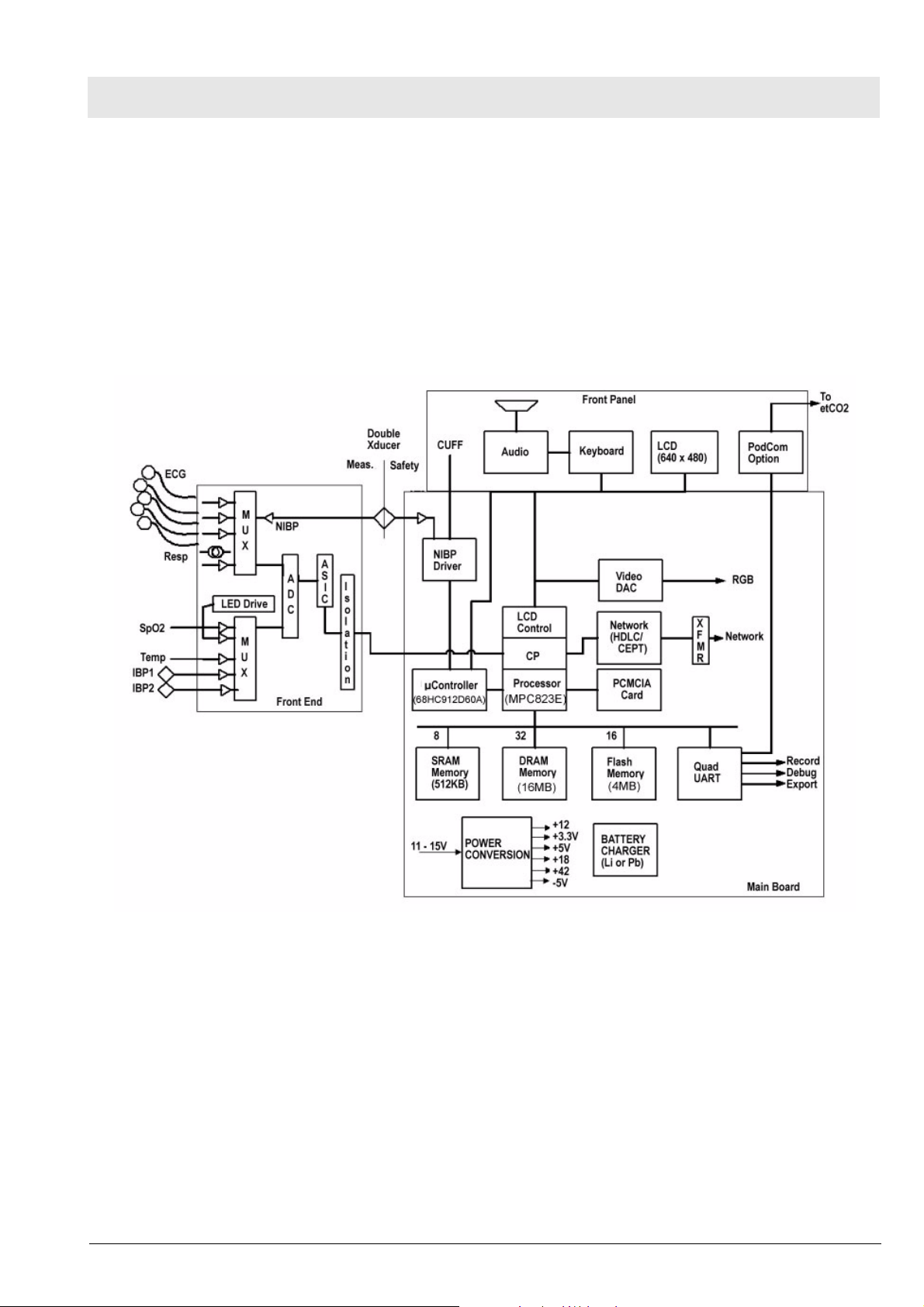
1Overview Infinity Gamma and Gamma XL Patient Monitors are configured monitors
running on one processor, an MPC823E Power PC processor, which attends
to all monitoring functions, controls all graphics functions, generates video
and timing signals for the LCD screen, and interfaces with the PCMCIA card
and USB port. It also performs several peripheral control functions, such as
NIBP control, audio volume control, and timing generation for the front end.
See Figure 1.
Gamma_Gamma_XL_SM_Function_Description.fm 03.12.04
Figure 1 Infinity Gamma / Gamma XL Patient Monitor Block Diagram
2 Parameter Inputs The data acquisition front end acquires and digitizes signals derived from a
three-, five-, or six-electrode ECG patient lead set, a Nellcor® or Masimo®
SpO2 transducer, an Impedance respiration measurement system, a thermistor-based Temperature transducer, and two strain-gauge IBP transducers
(IBP2 = locked option). The NIBP main transducer signal is digitized together
with the rest of the front end parameters. See Section 4 Front End and Section 5 Physiological Parameter Data Acquisition for more detailed information.
3Main PC Board The Main MPC823E Power PC processor not only attends to monitoring
functions, but also controls all graphics functions, generates the video and
timing signals for the LCD screen, interfaces with the PCMCIA card and USB
All rights reserved. Copyright reserved.
Dräger Medical AG & Co. KGaA 6013.053 Revision 0 Released
15

Function Description Gamma / Gamma XL Patient Monitor
port, and controls the network link. In addition, it performs a host of peripheral
control functions, such as NIBP control, audio volume control, and timing
generation for the front end.
3.1 LCD Control A set of buffer/drivers are used to drive the 6.5” screen in Gamma monitors or
the 8.3” screen in the Gamma XL monitors. In parallel, a triple video DAC
generates analog RGB signals for an external VGA monitor (typically a CRT
or LCD).
3.2 Network Interface The Infinity Gamma / Gamma XL Monitor interfaces with the physical inter-
face device (e.g., IDS) automatically, when connection to the device has been
detected. Connections to Infinity network services are established and maintained by software components resident on both the Gamma and Gamma XL
Monitor and the physical interface device.
3.3 Front Panel Circuitry The front panel circuit processes the audio information, drives the fluorescent
tubes on the LCD, implements a secondary alarm in case the unit resets or
turns off, and routes the video and timing signals to the screen. It also routes
the UART signal coming from the Pod interface to the main board Quad
UART.
3.4 Pod Interface The Pod Interface generates an isolated voltage to power the pod and also
converts the Pod Comm protocol from the pod into a UART stream that can
be interpreted by the microprocessor.
3.5 Battery Control and
ON/OFF Control
3.6 BOOT Process,
Flash Memory, and
DRAM
The Pb-acid or Lithium battery charging and discharging cycles are controlled
by a special charger circuit. The circuit initiates a charge cycle when commanded by the microcontroller. The charge cycle for a Pb-acid consists of a
bulk charge period in which the battery is being supplied a constant current of
~400mA, a constant voltage period in which the battery voltage is held constant at ~14.8V and the current is allowed to diminish as the charge
approaches 100%, and a float cycle in which the voltage is maintained at
~13.7V. For Lithium batteries, the charger circuit acts as a constant voltage
source of 16.8V. The battery is charged from a switching supply controlled by
the charger chip. The microcontroller also reads the front panel keys and the
rotary knob, encodes the information coming from them, and routes it to the
main processor. When the On/Stdby key is pressed, it turns the monitor on
and off. In addition, the microcontroller controls the NIBP safety timer.
The BOOT EEPROM contains the boot code and is preprogrammed at the
factory. It can be reprogrammed in the field by means of a special PCMCIA
card, if required. (Contact your local Dräger Medical service representative.)
The executable software normally resides as compressed operational code in
Flash memory. When the 68HC912D60A microprocessor senses that the
on/off switch on the front panel has been pressed, it turns on (or turns off) the
3.3V and 5V supplies. As the 3.3V supply turns on, it wakes up the MPC823E
main processor, which begins execution from the BOOT PROM. During boot
initialization, the main processor attempts to read the Memory Card to detect
authorized software. If a authorized software memory card is present, the
software is loaded from the card. Otherwise, the main processor loads software from the Flash to the main processor DRAM, from which it completes
initialization and enters operational mode. DRAM contains expanded operational code, and data space variables and stacks.
16
Dräger Medical AG & Co. KGaA 6013.053 Revision 0 Released
Gamma_Gamma_XL_SM_Function_Description.fm 03.12.04
All rights reserved. Copyright reserved.

Gamma / Gamma XL Patient Monitor Function Description
3.7 SRAM The 512K x 8 SRAM is battery backed up and is used for error logs, trends,
recordings and other non-volatile memory uses.
3.8 68HC912D60A
Microcontroller
On/Off control When the ON/OFF push button (either local or remote is pressed), the micro-
NBP Valve modulation When directed by the main processor, the microcontroller supplies modula-
NBP Safety Timer When the pump or the valve V2 are turned on, the microcontroller initiates a
Battery Charger The microcontroller initiates a battery charge when needed, and stops the
The 68HC912D60A microcontroller, with 64K of EEPROM and 2048 bytes of
RAM, is powered as long as there is a main supply plugged into the system
or when the user presses the ON/OFF button. The code is stored in its internal flash memory, but can be downloaded from the MPC823E. The microcontroller performs the following functions:
controller activates the 3.3V and 5V supplies, which wakes up the MPC823E
through a power-on reset. In addition, the microcontroller has control over a
flyback supply, which comes on any time the unit is plugged into AC power (in
order to charge the battery) or is turned on.
The microcontroller also reads the front panel keys and the rotary knob,
encodes the information coming from them, and routes it to the main processor.
tion signals for the two NBP manifold valves.
128 sec. timer (90 sec. or 60 sec. for neonates) which, if exceeded, produces
an NBP fault and results in cut off of main 12V power to the NBP manifold.
charging process when the battery reaches full capacity. It can recognize
whether a Pb or Lithium battery is connected into the system, and directs the
battery controller chip to charge to different levels depending on the battery
type. See Section 3.5 Battery Control and ON/OFF Control. The microcontrol-
ler also acquires the battery voltage and current for monitoring purposes.
Recorder Power The microcontroller controls power applied to a stand-alone R50 Recorder.
Main Audio Generator The microcontroller generates the fundamental audio frequency of the unit’s
tone generator, as directed by the main microprocessor.
USB Power When directed by the MPC823E, the 68HC912D60A microcontroller turns
power ON/OFF on USB buss and determines the transaction speed.
4 Front End All physiological signals (except etCO2) are digitized through a high speed
multiplexing system and a common 16 bit ADC. The data is then transferred
through the isolation barrier to an HDLC port in the main processor, where it
is digitally filtered and processed.
4.1 NBP Control The NBP main transducer signal is digitized together with the rest of the front
end parameters. However, the redundant (overpressure) transducer is processed separately on the grounded end of the board. The pump on/off signal
and valve enable signals are generated off of the MPC 821 microprocessor.
The PWM signals for the valve flow control and the redundant safety timer
are implemented in a separate microcontroller (MC68HC912D60A).
4.2 Safety • Patient isolation withstands 5kV during defib.
• Leakage currents are limited to safe values normally and during single
fault conditions.
Gamma_Gamma_XL_SM_Function_Description.fm 03.12.04
• Patient is protected against electrosurgical burns at the electrodes.
All rights reserved. Copyright reserved.
Dräger Medical AG & Co. KGaA 6013.053 Revision 0 Released
17

Function Description Gamma / Gamma XL Patient Monitor
• Defibrillation protection does not drain excessive current away from the
patient.
• Specially shielded connectors and cables are used to provide excellent
immunity up to 1000MHz and can not be touched by the patient even
when disconnected.
• Single cable from MultiMed Pod to main Gamma / Gamma XL Monitor
unit reduces clutter between bed and monitor.
Figure 2 Front End
5 Physiological
Parameter Data
Acquisition
Transducers gather physiological data at the patient and feed them into the
small MultiMed Pod at the bed. The MultiMed Pod in turn is connected via a
3-meter cable to the front end in the main unit where analog ECG, Respiration, Temperature, and SpO2 signals are converted to digital form and sent
through isolators for processing.
5.1 ECG/Resp The MultiMed Pod located close to the patient accepts a set of 3, 5 or 6
shielded ECG electrode leads, an SpO2 (Nellcor) cable adapter, and a temperature sensor. The ECG section contains RF filters, and overvoltage
clamps that include 1k series resistors to limit shunting of defibrillator current.
The SpO2 and temperature sections also contain RF filters. Impedance respi-
18
Dräger Medical AG & Co. KGaA 6013.053 Revision 0 Released
Gamma_Gamma_XL_SM_Function_Description.fm 03.12.04
All rights reserved. Copyright reserved.
Gamma / Gamma XL Patient Monitor Function Description
ration is sensed through the ECG electodes. Void-free potting and internal
shielding enable compact containment of high voltage defibrillator and electrosurgery pulses. The small interconnecting cable to the main assembly is
captive at the MultiMed POD but plugs into the MultiMed front end via a specially shielded connector.
The front end accepts physiological signals from the MultiMed POD connector and feeds temperature, respiration, and ECG signals via RF filters, configuration multiplexers, and pre-amplifiers to a high-speed multiplexer driving a
16-bit analog-to-digital (A/D) converter. The data stream is sent to the Main
Processor board via an opto-isolator. Control commands from the Processor
are sent out to the front end on a similar isolating link. Isolated DC power is
also provided.
The ECG signals are conductively coupled to the isolated circuits via currentlimiting series resistors, whereas the SpO2 signals are optically isolated at
the transducer. Temperature signals are doubly insulated at the patient by
disposable boots on the sensors. AC (40kHz) excitation currents for respiration monitoring are dc-isolated by high-voltage ceramic capacitors.
The A/D samples the following parameters:
Table 1 Parameter Sampling Table
Parameter # of Channels
ECG 4
Pace 2
SpO2 Red 1
SpO2 IR 1
NBP 1
Resp 1
Te mp 2
The hardware pace detector monitors the ECG signal in two of the four channels (those not connected to the chest leads). All other signals are decimated
and filtered using digital signal processing in the MPC823E. High oversampling rate is required to minimize the requirements (and size) of the analog
anti alias filters. Superior rejection to ESU and other types of interference is
achieved with this type of design.
5.1.1 ECG • Bandwidth is set flexibly by software filters.
• Reconfigurable neutral selector can drive any electrode.
Gamma_Gamma_XL_SM_Function_Description.fm 03.12.04
• Lead-on detection functions with even poor electrodes.
• Calibration voltages can be superimposed on patient wave-forms or onto
flat baselines.
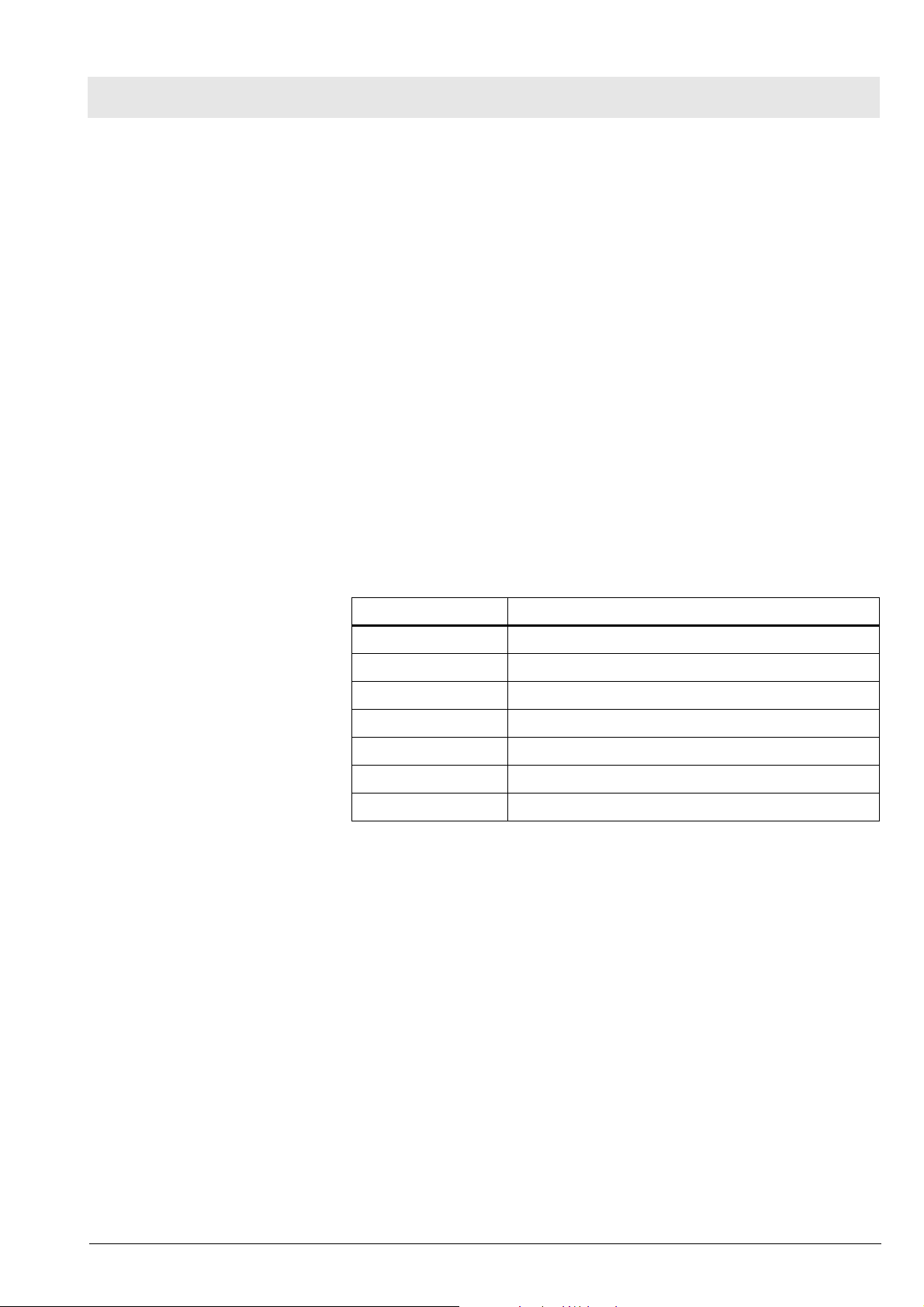
See Figure 3. Composite electrocardiographic (ECG) signals generated by
the heart and by a pacemaker are filtered to reduce RF interference from
impedance respiration and electrosurgery and then injected with dc lead-off
detection currents. Over-voltage clamps protect the semiconductors from the
surges passing the spark gaps in the MultiMed Pod and also reduce the dc
All rights reserved. Copyright reserved.
Dräger Medical AG & Co. KGaA 6013.053 Revision 0 Released
current applied to the patient due to a component fault.
19
Function Description Gamma / Gamma XL Patient Monitor
Figure 3 Lead-Forming Network
5.1.2 Lead Selection A lead-forming network following the RF filter generates the necessary refer-
ence points for electrocardiographic measurements. Both normal leads (I, II,
III, V1 and V2) and augmented leads (aVL, avR, and avF) can be obtained.
Four differential channels generate the main axes I, II, V1 and V2. The
remaining leads are derived mathematically as indicated in the vector diagram of Figure 3.
5.1.3 Lead-Off Detection Lead-off detection is accomplished by introducing a very small current into
each patient electrode, which would drive the corresponding input high if it
were disconnected. A set of five comparators detects a lead-off condition.
5.1.4 Low-Pass Filtering and
Common Mode
Enhancement
The ECG preamplifier has a flat frequency response of 0.5 - 40Hz, with a
software notch filter at 50/60 Hz. A 180° combined signal drives the neutral
electrode to increase the CMMR.
5.2 Respiration Impedance respiration is monitored by injecting a 40 kHz square wave of cur-
rent into the RA electrode. The resulting 40 kHz voltage drop between the RA
+ LL electrodes is proportional to the impedance. Especially balanced true
current sources do not load the ECG electrodes or distort the ECG morphology. The returning 40 kHz differential voltage is amplified, synchronously
demodulated, and low-pass filtered. An AC-coupled stage with an “autobloc”
DC restorer feeds the input to the A/D converter with a nominal output of 60
mV per Ohm.
Gamma_Gamma_XL_SM_Function_Description.fm 03.12.04
All rights reserved. Copyright reserved.
20
Dräger Medical AG & Co. KGaA 6013.053 Revision 0 Released
Gamma / Gamma XL Patient Monitor Function Description
5.3 SpO2
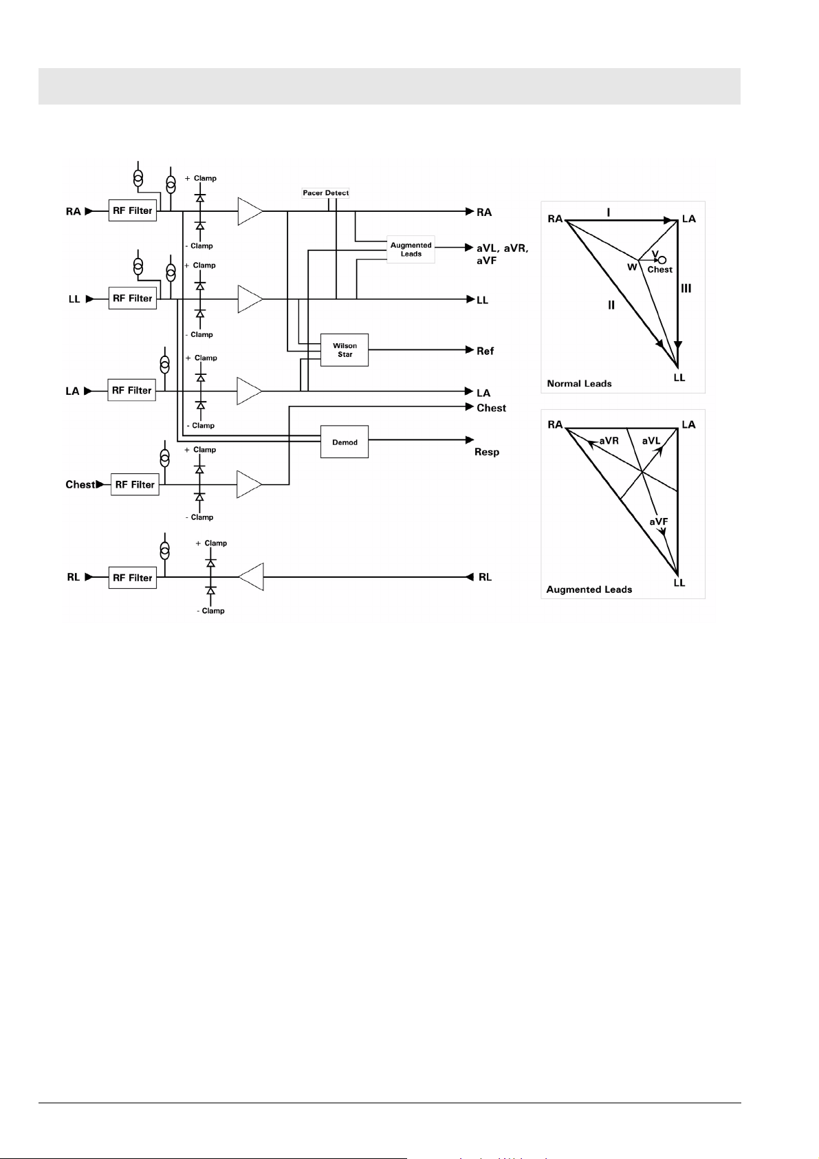
Figure 4 SpO2 Functional Block Diagram
The pulse oximeter circuit uses a Nellcor® sensor to detect the oxygen saturation level in arterial blood flow. Determination of the concentration of oxygen in the blood is based upon the principle that the absorption of red (R)
light depends on the degree of oxygenation of the blood, whereas the absorption of infrared (IR) radiation is relatively independent of oxygenation and
causes only constant attenuation. See Figure 4. In the SpO2 sensor, R and
IR light emitting diodes (LEDs) are alternately pulsed ON at a 25% duty cycle.
The light is transmitted through a well-perfused part of the body, such as a
fingertip or an ear lobe. The intensity of light (including ambient) transmitted
through or scattered by the blood is converted to a current by a photodiode in
the sensor. The current that appears when both LEDs are OFF depends
mainly on the ambient light, which is later subtracted to leave only the R or IR
signal levels. The large dynamic range of the light intensities requires constant automatic monitoring and adjustment.
The intensities of the R and IR sources are independently controlled by two
digital-to-analog converters (DACs) attenuating the 2.5 V reference. These
levels or zero are sequentially selected by a multiplexer, and converted to a
driving current which is further guided or inverted by an output multiplexer to
the LEDs in the sensor.
5.3.1 SpO2 Front End The primary purpose of the SpO2 front end is to convert the sensor’s analog
signal into individual digitized signals for the red and infrared analog signals
for processing by the microprocessor. See Figure 5. Circuitry in the front end
first eliminates the non-pulsatile component in the input signal, then demultiplexes the resulting pulsatile signal to separate the R and IR signal components, and finally converts the demultiplexed R and IR analog signals into
serial digital data streams.
Gamma_Gamma_XL_SM_Function_Description.fm 03.12.04
All rights reserved. Copyright reserved.
Dräger Medical AG & Co. KGaA 6013.053 Revision 0 Released
21
Function Description Gamma / Gamma XL Patient Monitor
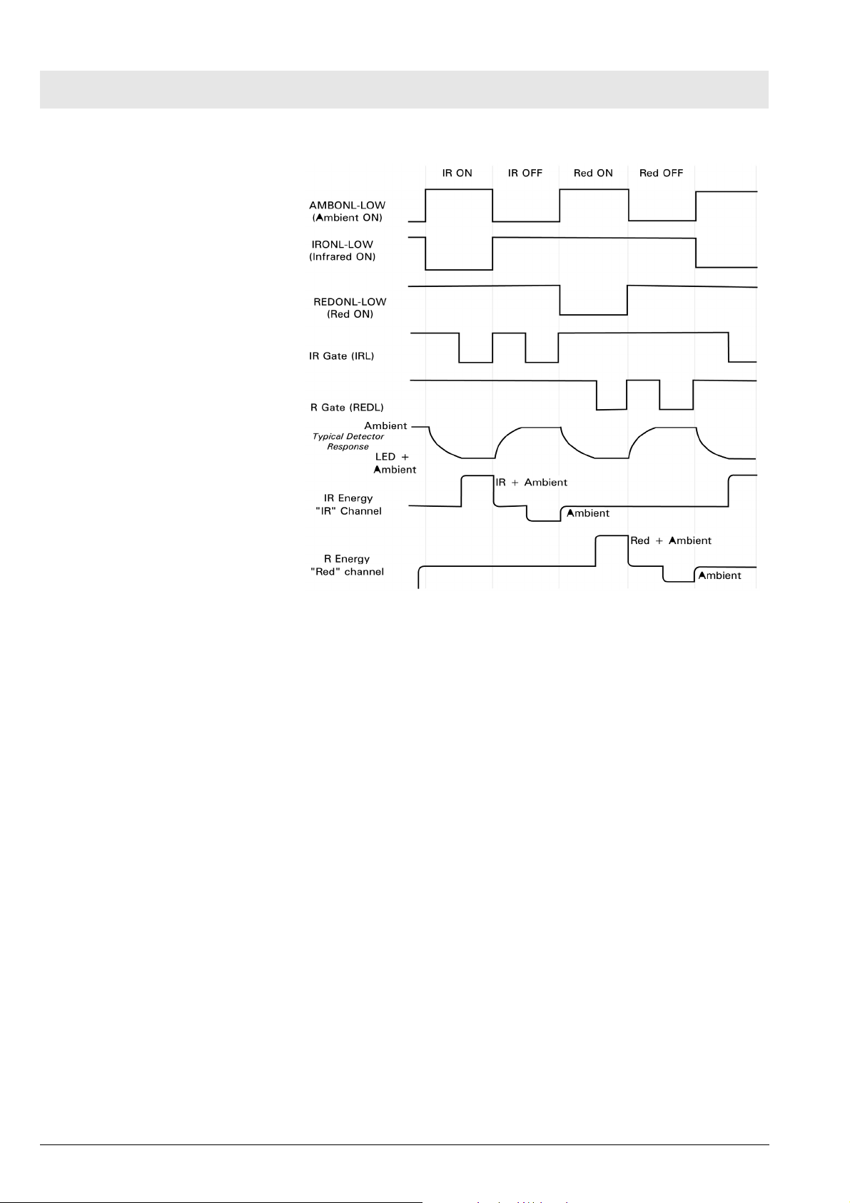
Figure 5 Sensor LED Timing Diagram
A sequence of light pulses, driven from the chopped current source in the
sensor LEDs, are passed through a finger or an earlobe to a photodiode. The
sensor LEDs are connected in an anti-parallel fashion on one pair of wires. A
timing generator controls the sensor LEDs and signal multiplexing/ demultiplexing (see Figure 5) by means of three control signals:
• IRONL (infrared LED)
• AMBONL (LEDS not lit)
• REDONL (red LED)
5.3.2 Input Stage A preamplifier converts the photocurrent to an equivalent voltage, and applies
it to a 20 Hz high-pass filter that removes the non-pulsatile component. The
output of the preamplifier is fed to a saturation detector.
5.3.3 Brightness Control If the output of the preamplifier is in saturation, the gate array provides a signal to the digital-to-analog converters (DACs), which controls the drive current to increase or decrease the brightness of the LEDs.
Controlling LED brightness extends the system dynamic range. For a very
transparent subject it may not be possible to reduce the gain to prevent saturation. In that event, the brightness must be reduced. An additional purpose is
to equalize the received amplitude of each wavelength. If both LEDs are
turned ON to maximum brightness, and the software finds an extraordinary
difference between the two, the microprocessor tends to reduce that difference by equalizing the R or IR brightness signals.
22
Dräger Medical AG & Co. KGaA 6013.053 Revision 0 Released
Gamma_Gamma_XL_SM_Function_Description.fm 03.12.04
All rights reserved. Copyright reserved.
Gamma / Gamma XL Patient Monitor Function Description
5.3.4 Ambient Light Rejection
Amplifier
5.4 Invasive Blood Pressure
The ambient rejection amplifier is a synchronous detector. The signal applied
to its inverting input is a composite of R, IR, and ambient signals. The noninverting input is the same signal gated by the timing generator. This synchronously multiplexes the IR, ambient, and R analog signals.
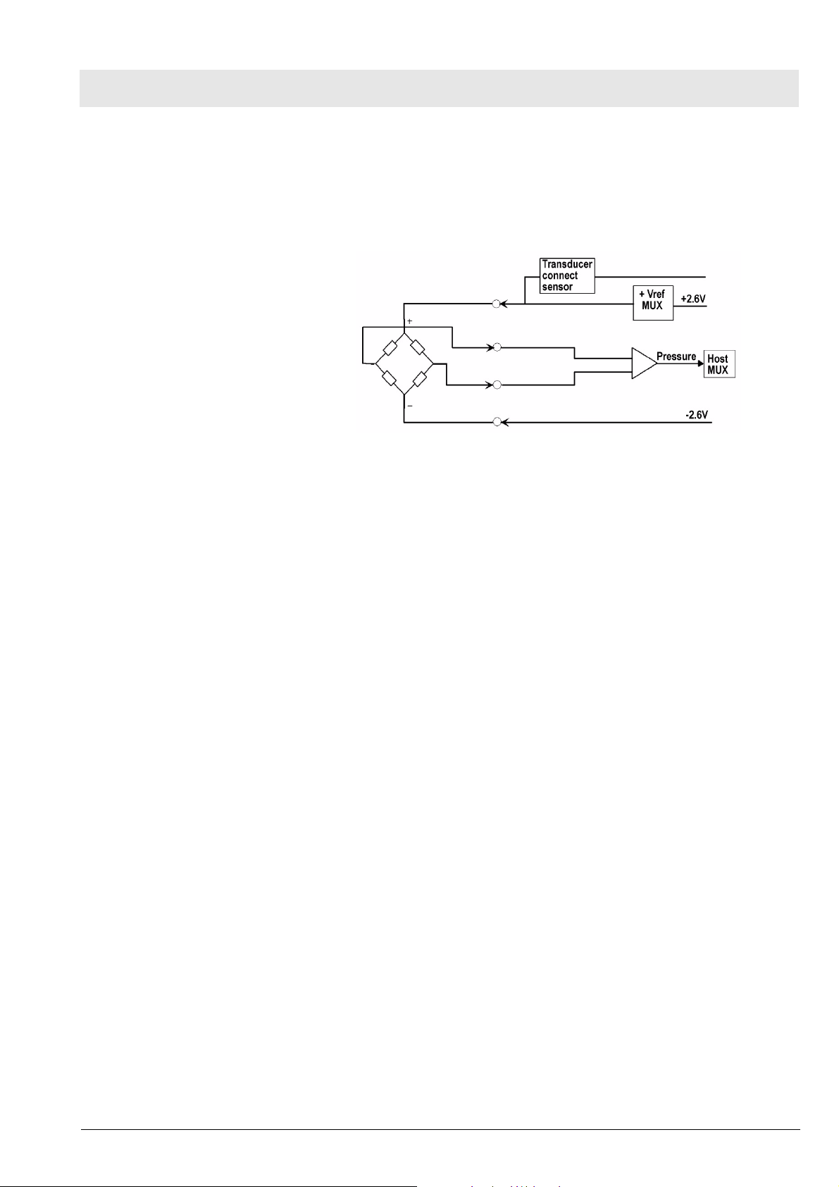
Figure 6 IBP Functional Block Diagram
The IBP circuit has been designed to be used with a strain gauge pressure
transducer. See Figure 6. The analog portion of the IBP circuit provides excitation voltages for resistance bridge transducers. These voltages are derived
from a reference which is also used to derive the A/D converter reference
voltage. At the circuit input, a resistor divider network provides for transducer
unplugged detection. R-C filtering and protection diodes limit the effects produced during electrosurgery, defibrillation, and other such procedures. A
selector multiplexer allows for the insertion of calibration signals into the
amplifier stage. The multiplexor feeds the pressure signal to a buffer amplifier, which in turn feeds the AD converter analog input. This allows the monitor to measure pressure signals in a range greater than ±700 mmHg with a
resolution of approximately .02mmHg/LSB.
Gamma_Gamma_XL_SM_Function_Description.fm 03.12.04
When no pressure transducer is plugged into the monitor, the resistor divider
network puts a negative signal into the instrumentation amplifier, which propagates through the system to indicate the unplugged condition.
All rights reserved. Copyright reserved.
Dräger Medical AG & Co. KGaA 6013.053 Revision 0 Released
23

Function Description Gamma / Gamma XL Patient Monitor
5.5 Non-Invasive Blood
Pressure
Figure 7 NBP Functional Block Diagram
5.5.1 NBP Subsystem The NBP subsystem consists of the following components:
• pump
• two modulating valves
• strain-gauge pressure transducer
• overpressure sensor
• pneumatic manifold
In addition, an electronic data acquisition and control system measures and
digitizes the pressure pulses as the cuff inflates and deflates. Pump and
valve control circuitry engage these elements as needed in the measurement
cycle. Several interlock systems and expiration timers ensure the safety of
the equipment in case of single point failures.
The Gamma / Gamma XL Monitor NBP circuit uses a cuff and the oscillometric method to determine blood pressure without using a microphone. A straingauge pressure transducer is DC-coupled to a 16-bit A/D converter, so that
cuff pressure is measured with adequate resolution to detect blood pressure
pulses. This eliminates the need for a separate ac-coupled measurement
channel, with its associated distortion and long transient recovery.
5.5.2 NBP System Description The combination of high-resolution A/D conversion and digital filtering,
together with wide-range linear deflation control allows the circuit to measure
blood pressure very rapidly and accurately, and to recover quickly from
motion artifacts. The non-invasive pressure system is composed of the following components:
• pneumatic assembly
24
Dräger Medical AG & Co. KGaA 6013.053 Revision 0 Released
Gamma_Gamma_XL_SM_Function_Description.fm 03.12.04
All rights reserved. Copyright reserved.

Gamma / Gamma XL Patient Monitor Function Description
• electronic circuitry, mounted on the Main CPU Board
Pneumatic Assembly The pneumatic assembly contains a pump, two modulating valves (V1 and
V2), two air filters (intake and manifold), and a manifold assembly which interconnects these components. The pump provides the pressurized air to inflate
the blood pressure cuff. V1 and V2 control the air flow during the deflation
phase of a blood pressure measurement. V1 is a normally-closed exhaust
valve with a relatively small orifice (relative to V2). V2 is a normally-open
exhaust valve with a relatively large orifice. The pump speed can be controlled to permit accurate inflation pressures for special applications. The filters prevent potential contamination of pneumatic components by debris
coming from the cuff or hose.
Electronic Circuitry The electronic circuitry, mounted on the Main CPU Board, contains the elec-
trical drivers for the pump, the valves, and its power supplies. In addition, the
readback from the pressure transducer is processed through the floating section ADC. The software data acquisition and algorithm processing is performed in the MPC823E main processor.
5.5.3 Operation The measurement sequence consists of an inflation phase, in which the air
pump inflates the cuff, which has been wrapped around the patient’s limb
(typically the upper arm or thigh) to a predetermined pressure. At this point,
the blood circulation to the limb is occluded. The monitor then linearly
deflates the cuff at a software-controlled rate during which time the blood
pressure parameters are determined by digital filtering and analysis of waveform data obtained from the pressure transducer during the deflation cycle.
Inflation Phase When a blood pressure measurement is initiated (via software or front panel
fixed key), V2 closes, the pump turns ON, and the pressure transducers monitor the ensuing pressure rise. When the pressure has reached the target
inflation pressure, the pump turns OFF and a dynamic braking circuit rapidly
brings the pump to a halt. The target inflation pressure adapts to the patient’s
systolic pressure, just occluding the blood flow. The software monitors the
slope of the pressure curve during inflation to estimate the cuff volume, a factor used in the deflation sequence.
Deflation Phase After the pump stops, there is a short delay to allow thermal transients to set-
tle. Either V1 or V2 is modulated to control the deflation rate. The choice of
V1 or V2 and the initial pulse width is made based on the estimated cuff volume determined during the inflation cycle. The chosen valve is modulated at
a 20 Hz rate, and the pulse width (open time) is continuously adjusted to provide a linear deflation rate. If initial deflation was started with V1, the software
may determine that it needs to switch to V2 to maintain proper deflation. In
either case, V2 opens fully (de-energizes) when the measurement cycle is
ended to allow for rapid and complete deflation.
5.5.4 NBP Hardware Pump control circuitry provides the following three functions:
• limits the current to the pump when it starts, to prevent power supply
overload
• dynamically brakes the pump when the pump is shut off
Gamma_Gamma_XL_SM_Function_Description.fm 03.12.04
• provides a closed-loop speed control for special low-flow operations
Speed Control Pump speed is controlled by measuring the back-EMF generated by the
motor winding, which is directly proportional to the speed. However, to obtain
a measurement of the back-EMF, the drop caused by copper losses must be
added to the voltage appearing on the motor winding. The speed control
effectively drives the pump at constant full speed.
All rights reserved. Copyright reserved.
Dräger Medical AG & Co. KGaA 6013.053 Revision 0 Released
25

Function Description Gamma / Gamma XL Patient Monitor
Current Limit Dedicated circuitry limits the current to the pump. When the current on the
pump is approx. 363 mA, the current loop takes over and limits its value. The
microprocessor and an N-channel FET turn the pump ON.
5.5.5 Valve Control A relatively high pulse voltage is used to drive V1 and V2 to get quick
response and extend the pulse-width flow control range.
5.5.6 Power Supplies Separate control logic supplies voltage (+12V) to the pump and V2 to provide
them with redundant turn-off capability. Without +12V the pump cannot run,
and V2 can neither close nor remain closed. Power supplies necessary for
operation of the NBP circuitry are derived as follows:
+5V and -5V Supply The +5V and -5V for the NBP analog circuitry are derived from the floating
section.
+12V Supply The +12V drives the NBP pump and both modulating valves. The Gamma /
Gamma XL Monitor flyback supply produces the +12V. This circuit produces
several voltages needed for monitor operation. The main flyback regulation
loop is closed around the +12V output, therefore making it the best regulated
of the multiple voltages generated.
In operation, a resistor network samples the +12V output and feeds it into the
controller chip error amplifier, which compares it to an internal reference. The
duty cycle of the switching transistor is adjusted to null this reference. A separate current feedback loop is used to stabilize the circuit and provide current
limiting protection.
+36V Regulator A +36V supply used to accelerate the energizing of the valve coils is derived
from the 42V raw supply generated by the flyback supply.
5.5.7 Power Supply Monitor The power supply monitor circuit provides reset logic to the microprocessor,
and the redundant power switch circuit, both at power-up and in the event of
a power failure or voltage drop. The heart of the monitor is a power supervisor chip. At power-up, the control line is held low for a period of about 200
ms, after which the voltage rises to the +5V level. After start-up, any dip in the
+5V that causes the output to go to less than +4.75V causes the same
sequence. A resistor network is used to monitor the +12V supply. When the
voltage on the reference signal falls below +1.25V, a reset sequence similar
to the one described above ensues. The +5V and -5V are monitored via the
floating section ADC.
5.5.8 Safety Timer The safety timer becomes active only after starting the pump at least one
time. Once the pump has been activated, the timer circuit operates regardless of whether the pump has been turned off. Starting of the pump is sensed
by voltage developed across the pump sense resistor. If as a result of some
failure, hardware or software, the pump continues to run longer than the timer
expiration period, a microcontroller output rises and opens a redundant
switch, which causes the pump to turn off and V2 to open.
The safety timer period is derived from the microcontroller clock. Note that,
for redundancy purposes, the safety timer is implemented not in the
MPC823E but in the 68HC912D60A microcontroller.
26
Among other signals multiplexed into the floating section data stream are
power supply monitor voltages. Measuring these voltages gives an indication
of the integrity of the power supplies and the A/D converter voltage reference.
Dräger Medical AG & Co. KGaA 6013.053 Revision 0 Released
Gamma_Gamma_XL_SM_Function_Description.fm 03.12.04
All rights reserved. Copyright reserved.
Gamma / Gamma XL Patient Monitor Function Description
5.5.9 Pressure Channels Pressure fluctuations in the cuff change the balance of the pressure mea-
surement bridge, resulting in a differential voltage which is fed into an amplifier. The gain of the amplifier is determined by the setting of a calibration
potentiometer. This potentiometer is initially adjusted in the factory, and from
then on the calibration should be checked every year.
The overpressure hardware is fed by a single power source. This increases
safety of the system, since a failure of the reference voltages does not impact
operation of the overpressure channel. An overpressure test is performed at
each power-up cycle to ensure that the overpressure circuitry is working. Any
error detected in the overpressure comparator circuit is fed to the redundant
power switch circuitry described above. The software overpressure detection
is completely independent of the overpressure circuitry.
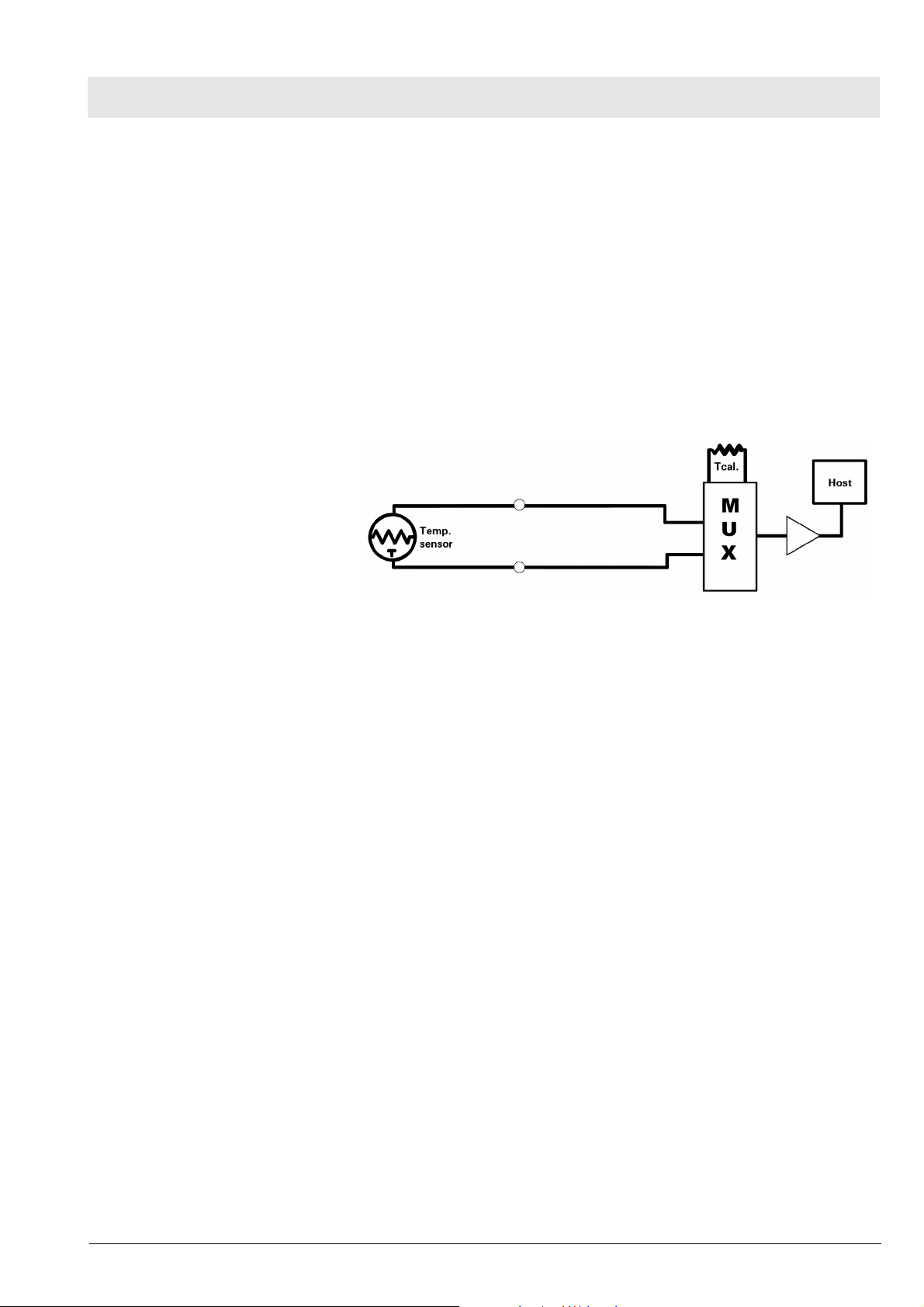
5.6 Temperature Circuit
Figure 8 Temperature Functional Block Diagram
Temperature measurements are made using a thermistor probe that is electrically equivalent to YSI‚ 400 series probes. See Figure 8.
5.6.1 Reference Networks Two independent reference networks are used to verify correct circuit function by measuring the difference between the reference network ratio values
(simulating -5°C and +50°C temperatures), and reporting an error if that difference exceeds the expected range of values. The reference networks are
also used to cancel offset and gain errors in the measure-ment circuits. The
measurements of the two references allows for the determination of circuit
offset and gain within the accuracy of the reference networks.
5.6.2 A/D Converter A resistor network linearizes the voltage versus temperature curve of the
thermistor to within ±2°C. Later the curve is further linearized to 0.01°C, using
a look-up table in the microprocessor. The maximum power to the thermistor
element is limited to 50 µW. To maintain high accuracy, all signal voltages are
ratiometric to the A/D converter voltage reference. The sensitive electronics
are protected from damage by an RF filter and an overvoltage clamp.
A multiplexer selects one of three inputs: T1, T-5, or T50. T-5 and T50 are
used in a two-point error correction algorithm, to measure the actual gain and
offset of the measurement circuit. The T-5 and T50 voltages are created by
precision resistor dividers, and are calculated to simulate the voltage that
would appear at T1 when a thermistor probe is at a temperature of -5°C and
50°C, respectively.
Gamma_Gamma_XL_SM_Function_Description.fm 03.12.04
When a thermistor probe is disconnected from the measurement circuit, the
voltage at the input to the A/D converter reaches a value that is above positive full scale. The microprocessor is programmed to interpret a positive full
scale value from the A/D converter as a probe disconnect.
All rights reserved. Copyright reserved.
Dräger Medical AG & Co. KGaA 6013.053 Revision 0 Released
27

Function Description Gamma / Gamma XL Patient Monitor
6 etCO2 Pod
Figure 9 etCO2 Sensing Process Functional Block Diagram
The etCO2 pod non-invasively monitors end-tidal CO2 using a technique that
relies on the selective absorption properties of the CO2 to specific frequencies of infra-red radiation. See Figure 9 .
In the sensor a thick film infra-red source is pulsed at a rate of approximately
87 Hz, generating a broad- band spectrum of IR. Selective filtering separates
this into two narrow regions, one inside and one outside the band of CO2
absorption. The detector associated with the filter outside the band of CO2
absorption records the maximum level of the source energy since the signal it
receives is not affected by CO2. It provides a baseline which serves as a Reference for the level of CO2 in the airway.
The other detector senses a filtered energy level modified by the presence of
CO2. As the level of CO2 increases, the CO2 gas molecules in the airway
absorb more of the light energy and less signal reaches the detector. This
signal, converted by the detector, is referred to as the Data signal. Current
through the thick-film source is bidirectional to offset the tendency of particles
within the source to migrate when exposed to a strong unidirectional electric
field caused by current flow only in one direction. This keeps the structure of
the source uniform and enhances system integrity and life of the product.
To acquire a precise level of CO2, both channels are simultaneously sampled
and the level of CO2 is determined from the ratio of the Data and the Reference channels. The ratio is compared to a look-up table in memory to establish the correct value in units of mmHg.
The pod then sends the results to the PodCom input of the Gamma /
Gamma XL Monitor for further processing and display.
28
Dräger Medical AG & Co. KGaA 6013.053 Revision 0 Released
Gamma_Gamma_XL_SM_Function_Description.fm 03.12.04
All rights reserved. Copyright reserved.

Gamma / Gamma XL Patient Monitor Function Description
7 Power Supply Sys-
tem
Figure 10 Power System Block Diagram
The monitor can be powered from any of several sources --
• A lead-acid or lithium-ion battery, housed in the monitor
• A CPS (Communication/Power Supply), through a docking station,
• An IDS (Infinity Docking Station)
• An AC power adapter
As illustrated in Figure 10, the ac power adapter and the IDS are connected
in parallel. The monitor is normally powered by an IDS, in a “pick-and-go”
application, and by the ac power adapter in a stand-alone application. If both
supplies were to be connected simultaneously the one with a higher voltage
would take over.
Two solid state switches, the eliminator switch and the battery switch, govern
supply of power to the monitor and charging of the battery. In addition, there
are three DC/DC converters, two buck regulators that produce the main +5V
and +3.3V, and a multi-output flyback supply that generates three auxiliary
voltages, including the voltage that is used to charge the battery.
On/Off logic circuitry manages the condition of the switches and the DC/DC
converters under different circumstances, and responds to the On/Off pushbutton on the monitor front panel. The logic is implemented in the microcontroller.
7.1 Main Battery A lead-acid main battery should sustain autonomous operation of the monitor
for approximately 75 minutes. A lithium-ion main battery should sustain
autonomous operation of the monitor for approximately 180 minutes. When
the battery eliminator is connected, power to the load and charging power for
the battery is provided from the AC mains.
Gamma_Gamma_XL_SM_Function_Description.fm 03.12.04
To be fully charged, lead-acid batteries require a voltage of approximately
2.45 V/cell at 25C (14.7 V in Gamma / Gamma XL Monitors). This voltage
should not be sustained after full charge has been reached, however,
because the battery starts to outgas which reduces its life. Therefore, voltage
to the battery must be reduced to 2.30 V/cell at 25C. This is known as the
“float” voltage. At this voltage the battery can remain indefinitely connected to
the monitor, ready to deliver current when necessary. The charging circuitry in
All rights reserved. Copyright reserved.
Dräger Medical AG & Co. KGaA 6013.053 Revision 0 Released
29

Function Description Gamma / Gamma XL Patient Monitor
the Gamma / Gamma XL Monitor automatically varies the charging cycle.
Lithium-ion batteries require a constant charging voltage. See Section 3.5
Battery Control and ON/OFF Control above.
7.2 AC Power Adapter The ac power adapter is a regulated 12V (nominal) supply with enough cur-
rent capability to supply the load and charge the battery at the same time.
The eliminator switch (see Figure 10) is turned ON when the input voltage
exceeds 11.25 V, allowing the ac power adapter to feed the rest of the monitor circuitry. The battery is charged from the output of the flyback supply
through a regulating FET and a low-value sense resistor.
30
Dräger Medical AG & Co. KGaA 6013.053 Revision 0 Released
Gamma_Gamma_XL_SM_Function_Description.fm 03.12.04
All rights reserved. Copyright reserved.

Maintenance Procedures
31

32

Gamma / Gamma XL Patient Monitor Maintenance Procedures
Maintenance Procedures
1 Maintenance Proce-
dure
1.1 General Gamma and Gamma XL Patient Monitors require replacement of the lead-
acid battery (12 months), NBP air intake filter (24 months) and fluorescent
bulb (45K - 50K hours). Replacement of the fluorescent bulb, however,
requires partial disassembly of the monitor and is therefore considered a
repair procedure. An NBP calibration check is recommended to be performed
either annually or in accordance with local regulations.
1.2 Battery To obtain maximum life from a new lead-acid battery, install the battery into
the monitor and run the monitor on battery power for a period of 15 minutes.
After the 15 minute period, either plug in the monitor’s power adapter or lock
the monitor onto a powered docking station and charge the battery, or
remove the battery from the monitor and connect the battery to an external
charger. (This initial sequence is not needed for Li batteries.)
Note
When in storage or not in use for an extended period of time, lead-acid batteries self-discharge and develop a “float-charge” as a characteristic of the
self-discharge process. The “float charge” must be drained off before the
battery can be properly charged. If a new battery is immediately placed on
a charger, the “float charge” provides an incorrect indication of the battery’s
charge condition, and the charger may not fully charge the battery.
Between discharges, the lead-acid battery must be recharged as soon as
possible. Once charged, it can be stored for several months without recharging. Starting at a 100% charge level, at room temperature the battery self-discharges below the acceptable minimum in ≈ 6 months on a shelf and in ≈ 2
months in an unpowered spare monitor. Dräger Medical recommends that the
battery charge be maintained at >80% to maximize the battery’s capacity and
cycle life.
Warning
Dispose of used batteries in accordance with local regulations governing disposal of hazardous materials.
1.3 Replacing NBP Air
Intake Filter
All rights reserved. Copyright reserved.
Gamma_Gamma_XL_SM_Maintenance.fm 03.12.04
Dräger Medical AG & Co. KGaA 6013.053 Revision 0 Released
There are two NBP air filters: an air intake filter and a manifold filter. The air
intake filter is accessible from the top of the battery compartment and is
replaced periodically (every 24 months). The manifold filter is located in the
manifold subassembly itself and rarely requires replacement. Replacement of
the manifold filter is considered a repair procedure rather than a maintenance
procedure.
33

Maintenance Procedures Gamma / Gamma XL Patient Monitor
1.4 Safety and Function
Tests
Figure 1 Location of NBP Air Intake Filter in Battery Compartment
1. Open battery compartment door and remove battery.
2. Remove plastic cap covering air intake filter through opening in top of battery compartment. (See arrow in Figure 1.)
3. Withdraw filter from filter housing using needle-nose pliers.
4. Fully insert new filter into filter housing, with open end of filter facing
inward, and replace cap.
Note
NBP filters have an opening in one end. The end with the opening must be
inserted into the filter housing for the filter to function properly.
5. Reinstall battery and battery compartment door.
Dräger Medical recommends that a full functional verification be performed
annually. Also, some national jurisdictions require that a temperature calibration check and an NBP calibration be performed at least every two years.
Refer to appropriate Fault and Cause Tables if the monitor should fail any calibration check or functional verification procedure that cannot be rectified by
simple adjustment. Document test results on a copy of the Acceptance Test
Report (see Section 1.5 Acceptance Test Report.
1.4.1 Power Circuits and Startup
34
Dräger Medical AG & Co. KGaA 6013.053 Revision 0 Released
The following procedures check the monitor’s power circuits, power-up
sequence, and power-off indicator. Begin this procedure with monitor turned
off, main battery removed, and ac power adapter disconnected.
Gamma_Gamma_XL_SM_Maintenance.fm 03.12.04
All rights reserved. Copyright reserved.

Gamma / Gamma XL Patient Monitor Maintenance Procedures
AC Power Adapter 1. With power cord connected to a hospital-grade power source, plug ac
power adapter into monitor.
2. Verify that green Battery Charger LED on front panel of monitor illuminates.
Power-Up Sequence 3. Press ON/OFF switch on front panel, and verify following sequence of
events.
a) Power ON LED in ON/OFF key turns on, display illuminates and mon-
itor emits a brief tone.
b) Startup screen containing displays character changing colors as it
descends towards Dräger Medical Logo.
c) Monitor emits a brief tone and screen goes blank for a few seconds.
d) Pressure relief valve pulses.
e) Display reappears containing copyright notice, installed software ver-
sion, and message “Loading software, please wait...”.
f) MAIN screen replaces Startup Screen after several seconds.
Power Off Indicator 4. Press ON/OFF switch, and verify that monitor powers-down and a high
pitched tone sounds for ≈ 7 seconds.
5. Disconnect external power source from monitor, and verify that Battery
Charger LED turns off.
Battery and Charging Cir-
6. Install main battery.
cuit
Note
Battery should have at least 50% charge level, as indicated by the charge
level bar graph in the display message area.
7. Press ON/OFF switch on front panel, and verify the following:
• Monitor powers-up according to normal power-up sequence of
events. (Refer to power-up sequence in step 3.)
• Battery charge level indicator appears in message field on bottom left
hand side of display.
8. Plug in ac power adapter, and verify that the Green Battery Charger LED
on front panel of monitor illuminates, screen brightness increases, and
after ≈ 14 seconds, charge level indicator disappears.
1.4.2 Optical Encoder The Rotary Knob on the front panel controls an optical encoder for pointing to
and selecting fields and functions on the display.
1. After power-up sequence has completed, press Rotary Knob and verify
that fill color of New Patient NO prompt changes to white indicating that
you can now confirm value NO or change it to YES.
2. Turn knob one notch (detent, click) in either direction, and verify that
value in NO field changes to YES. Turn knob another notch, and verify
that value changes back to NO.
3. Choose YES, and verify that New Patient prompt disappears.
All rights reserved. Copyright reserved.
Gamma_Gamma_XL_SM_Maintenance.fm 03.12.04
Dräger Medical AG & Co. KGaA 6013.053 Revision 0 Released
35

Maintenance Procedures Gamma / Gamma XL Patient Monitor
1.4.3 TFT-LCD Display The Gamma Patient Monitor display is composed of an active-matrix, 6.5
inch TFT-LCD screen with backlite. The Gamma XL Patient Monitor display is
composed of an active-matrix, 8.4 inch TFT-LCD screen with backlite. Test
the TFT-LCD display as follows:
1. Verify that backlite provides sufficient and consistent background illumination for TFT-LCD.
2. Verify that there are ≤17 inoperative pixels (“stuck” ON or OFF).
1.4.4 Fixed Keys The following tests verify that membrane switches on the front panel are functioning properly, and that the signal from the key is processed by the Front
Panel Control PCB.
Note
Before beginning Key tests access Main menu. Select Monitor Setup →
Monitor Options → Speaker Volumes, and assure that Attention Tone Volume is set to other than OFF.
ON/OFF Key The ON/OFF key initiates the power-on sequence if the monitor is powered
off, and powers-off the monitor, initiating a brief power-off piezo alarm, if the
monitor is powered-on.
Note
This test can be omitted if the procedure in step 3 of Section 1.4.1 Power
Circuits and Startup has already been performed.
1. Press and momentarily hold ON/OFF key.
2. Verify that powered state of monitor changes from ON to OFF or from
OFF to ON.
3. Set monitor to powered-on state, if monitor powered off.
Main Screen and Menu
Keys
The Main Screen key sets the display to the MAIN screen.
4. Press Menu key to display Main menu.
5. Press Main Screen key, and verify that Main menu extinguishes, and dis-
play returns to MAIN screen.
Alarm Silence Key The Alarm Silence key silences an alarm tone for one minute.
6. Assure that HR alarm is enabled, and without any input applied to Mul-
tiMed POD, plug MultiMed or MultiMed 6 cable into monitor. Monitor
should Alarm.
7. Press Alarm Silence key and verify that alarm ceases.
36
Alarm Limits Key The Alarm Limits fixed key calls up a setup table on which upper and lower
alarm limits for physiologic parameters can be assigned, and alarms and
alarm recordings can be enabled or disabled.
8. Attach patient simulator to MultiMed cable and set simulator as follows:
• ECG = Normal Sinus
• HR = 60 beats per minute (bpm)
Dräger Medical AG & Co. KGaA 6013.053 Revision 0 Released
Gamma_Gamma_XL_SM_Maintenance.fm 03.12.04
All rights reserved. Copyright reserved.

Gamma / Gamma XL Patient Monitor Maintenance Procedures
9. With MAIN screen displayed, press Alarm Limits fixed key.
10. Verify that Alarms Setup Table displays.
11. Set Upper HR alarm parameter to 55.
All Alarms Off Key The All Alarms Off key silences all alarms for a period of 3 minutes.
12. When alarm sounds (setup in previous step), press All Alarms Off key.
13. Verify message “All Alarms Off” appears on display.
14. Verify that after 3 minutes, alarm sounds and “All Alarms Off” message
disappears.
15. Set alarm parameter within alarm condition (60).
Record Key The Record key initiates a recording when monitor is connected, either
directly or via a network, to an R50 Recorder and otherwise initiates a stored
recording.
16. Press Record key.
17. Verify “Recording Started” appears in message field.
NBP Start/Stop Key The NBP Start/Stop key initiates or terminates the inflation cycle for the non-
invasive blood pressure monitor function.
18. Press Menu key. Access Monitor Setup → Monitor Options → Speaker
Volume → Medium.
19. Press NBP Start/Stop key.
20. Verify that monitor sounds a tone. (Cuff must Not be plugged into cuff
connector.)
Fast Access Key The Fast Access key allows access to the monitor’s bottom channel menu as
well as tabular trends, graphical trends and Event recall screen.
21. Press Fast Access key, Access Bottom Channel, then select All.
22. Verify that parameter boxes appear across bottom of display.
23. Access Bottom Channel → NBP.
24. Verify NBP parameter boxes across bottom of display.
25. Access Bottom Channel → Waveform.
26. Verify that 4th channel waveform is displayed.
Note:
A 4th display channel is standard in Gamma XL monitors, and available as
a option for Gamma monitors.
27. Access Trend graphs, then press rotary knob.
28. Verify that Trend Tables appear on display.
29. Access Trend Tables, then press rotary knob.
30. Verify that Trend Tables appear on display.
31. Access Event Recall, then press rotary knob.
32. Verify that Event Recall screen appears on display.
All rights reserved. Copyright reserved.
Gamma_Gamma_XL_SM_Maintenance.fm 03.12.04
Dräger Medical AG & Co. KGaA 6013.053 Revision 0 Released
37

Maintenance Procedures Gamma / Gamma XL Patient Monitor
1.4.5 ECG/RESP 1. Connect either a 3-lead, 5-lead, or 6-lead ECG cable from the Patient
Simulator into the MultiMed POD.
ECG/RESP Test Setup 2. Select HR parameter box and press rotary knob in to bring up ECG
menu.
3. Set all ECG Lead settings at default values and remaining parameters as
follows:
• Tone Source ECG
• Tone Volume Low
• Pacer Detection On
•QRS Marks On
• ECG Processing ECG1
• ECG Leads (set for type cable installed in step 1)
• Arrhythmia On
• Relearn depress knob to update Arrhythmia
4. Set simulator as follows:
• ECG = Normal Sinus
• HR = 80 beats per minute (bpm)
• amplitude = 1.0 mV
• RESPIRATION = Normal Rest.
• rate = 20 breaths per minute (BPM)
• ohms = 1.0
• LEAD SELECT = II/RL-LL
• BASELINE IMPEDANCE = 500
Waveforms/Digital Readouts/Tones
5. Verify the following:
• Waveform and HR correspond to data provided by simulator.
• Heart symbol blinks and pulse tone sounds for each QRS complex.
• White spike present at each QRS complex.
• RESP and HR digital readout correspond to settings of simulator.
6. Vary Tone Volume setting and verify that pulse tone volume changes.
7. Set Tone Volume to OFF, and verify that pulse tone stops.
Lead-Off Indicators 8. One at a time, disconnect each ECG lead from simulator.
9. Verify “Lead-Off” message appears in message area, pulse tone ceases,
and *** replaces digital heart rate in HR field for each lead removed in
step 8.
10. Reconnect all leads to simulator.
Alarm Function This procedure also tests that the alarm function of the monitor, as applicable
to all other patient parameters, is operational in the monitor.
11. In Alarm Limits Table, set HR alarm parameters as follows:
• Upper limit = 110 bpm
• Lower limit = 40 bpm
• Alarm = ON
12. Set simulator to HR = 120 bpm.
13. Verify that monitor responds with following Serious Alarm indications:
• HR in parameter field = 120
Gamma_Gamma_XL_SM_Maintenance.fm 03.12.04
All rights reserved. Copyright reserved.
38
Dräger Medical AG & Co. KGaA 6013.053 Revision 0 Released

Gamma / Gamma XL Patient Monitor Maintenance Procedures
• HR parameter field blinks and color changes.
• Serious Alarm tone sounds.
• Message HR > 110 appears in message area at bottom of display.
14. Reset simulator to HR = 80 bpm.Verify the following:
• HR parameter field returns to normal color
• HR returns to 80
• Message area continues to report cause of most recent alarm
15. Press Alarm Silence fixed key.
16. Verify that “HR > 110” ceases to be reported.
1.4.6 Asystole 1. Switch power to simulator OFF. Verify that HR parameter field reports
ASY, “Asystole” appears in message area at bottom of display, and monitor responds with Life-Threatening alarm.
2. Switch power to simulator ON.
1.4.7 SpO2 The Gamma Monitor reports oxygen saturation (SpO2) and pulse rate using
the spectrophotometric method. SpO2 software is checked on monitor powerup and also periodically while the monitor is in operation.
SpO2 Test Setup 1. Select SpO2 parameter box to access menu. Set parameters as follows:
• Pulse Tone Source SpO2
• Pulse Tone Volume Low
• Bargraph ON
• Averaging Normal
2. On Main Screen, highlight Channel 2 field and access menu. Set parameters as follows:
• Curve SpO2
• Size 20-30%
3. Apply SpO2 sensor to finger.
4. Verify an SpO2 reading of ≤94 in the monitors SpO2 parameter box.
(Allow approx. 20 seconds for reading to stabilize.)
Waveforms/Digital Readouts/Tones
5. Verify the following:
• Channel 2 displays SpO2 waveform, and digital SpO2 and pulse rate
(PLS) values.
• Pulse strength bar graph pulses SpO2 in field, ♥ symbol blinks in PLS
field, and pulse tone sounds for every detected pulse.
1.4.8 Temperature Using the Temperature Y-Cable input to the MultiMed Pod, set up the patient
simulator to supply a temperature input.
Functional Verification Procedure
1. Set the simulator for a standard 37°C.
2. Verify that monitor indicates temperature of 37 ±0.1°C.
3. Change simulator to temperature above and then below 37°C.
4. Verify that monitor readout agrees with simulator settings ±0.1°C.Perform
Temperature Calibration Check, if required by local Regulatory Standards.
All rights reserved. Copyright reserved.
Gamma_Gamma_XL_SM_Maintenance.fm 03.12.04
Dräger Medical AG & Co. KGaA 6013.053 Revision 0 Released
39

Maintenance Procedures Gamma / Gamma XL Patient Monitor
1.4.9 Temperature Calibration
Check
Recommended Equipment – Decade Resistor with ±0.1% accuracy (or fixed resistors with same accu-
Procedure 1. Connect MultiMed pod to input of patient monitor.
In some national jurisdictions temperature calibration must be checked periodically as specified in the Operating Instructions or User Guide (at least
every two years). Use the following procedure.
racy)
– Temp Adapter Cable, Art. No. 51 98 333 E530U (Optional)
2. Connect temp adapter cable to MultiMed Pod (if needed).
3. Connect temperature input to decade resistor.
Table 1 Resistance Value vs. Temperature
Resistance
Setting (Ω)
Set Tempera-
ture
Monitor
Reading
Tolerance Pass
6990 1.0 0.9 to 1.1
3539 15.0 14.9 to 15.1
1355 37.0 36.9 to 37.1
843.2 49.0 48.9 to 49.1
4. For each resistance value in Table 1, verify that monitor reports “Set Tem-
perature” value ±0.1°C.
5. Document test results on a copy of Acceptance Test Report.
1.4.10 etCO2 (if installed) The etCO2 Pod enables the Gamma/Gamma XL Monitor to non-invasively
monitor end-tidal CO2 (etCO2) using a technique that relies on the selective
absorption properties of CO2 to specific frequencies of infrared radiation. The
pod automatically compensates for variations in ambient barometric pressure
if set to automatic mode. Before beginning this procedure, use a mercury column barometer or equivalent other device to determine local atmospheric
pressure. Record this value_________.
1. Press Main screen key.
2. Click on etCO2 parameter box.
3. Click on etCO2 source.
4. Select POD nd click knob.
5. Press Main Screen key.
6. Connect Sensor (without adapter) to etCO2 pod and pod to monitor.
(Observe “etCO2 Sensor Warming Up” in message field at top of display.)
7. After “etCO2 Sensor Warming Up” disappears (approximately 2 minutes),
select etCO2 parameter box and in etCO2 setup menu select “More”.
8. Select Atm Press Mode - Manual.
9. Select Atm Pressure and set value as recorded above.
10. Press Main Screen key.
11. Select etCO2 parameter box and in etCO2 Setup menu, select “Sensor
Cal.”
12. After “etCO2 Place Sensor On Zero Cell” appears at top of display, place
sensor on Zero Cell.
40
Dräger Medical AG & Co. KGaA 6013.053 Revision 0 Released
Gamma_Gamma_XL_SM_Maintenance.fm 03.12.04
All rights reserved. Copyright reserved.

Gamma / Gamma XL Patient Monitor Maintenance Procedures
13. Verify “etCO2 Calibrating Sensor” appears in message field, followed by
“etCO2 Place Sensor on Ref Cell”.
14. After “etCO2 Place Sensor on Ref Cell” appears, place sensor on Reference Cell.
15. Verify that ”etCO2 Verifying Sensor Cal”, appears, then “etCO2 Sensor
Cal Verified” appears simultaneously with a tone.
16. Verify reading in etCO2 parameter box = 38 ±2mmHg.Remove reference
cell, insert adaptor into sensor and press Main Screen key.
17. For adapter calibration, refer to corresponding User’s Guide.
Note:
Refer to SCIO Service Manual for SCIO tests.
1.4.11 Non-Invasive Blood
Pressure
Figure 2 Test Setup
System Setup and Pneumatics Leakage Test
Set up NBP Calibration assembly (28 77 855) as illustrated in Figure 2.
Assure that pneumatic leakage is within specifications before continuing to
Functional and Calibration Check.
1. Power-up monitor.
2. After MAIN screen displays on monitor, double-click rotary knob to accept
“New Patient.”
3. Turn rotary knob until NBP field is highlighted, then depress knob.
4. Set following in NBP parameter field menu:
• Interval Mode: OFF
• Calibration Mode: ON (Observe “NBP Cuff 0 mmHg” appears in lower
right area of NBP field
• Inflation Mode: Adult: 270
All rights reserved. Copyright reserved.
Gamma_Gamma_XL_SM_Maintenance.fm 03.12.04
Dräger Medical AG & Co. KGaA 6013.053 Revision 0 Released
41
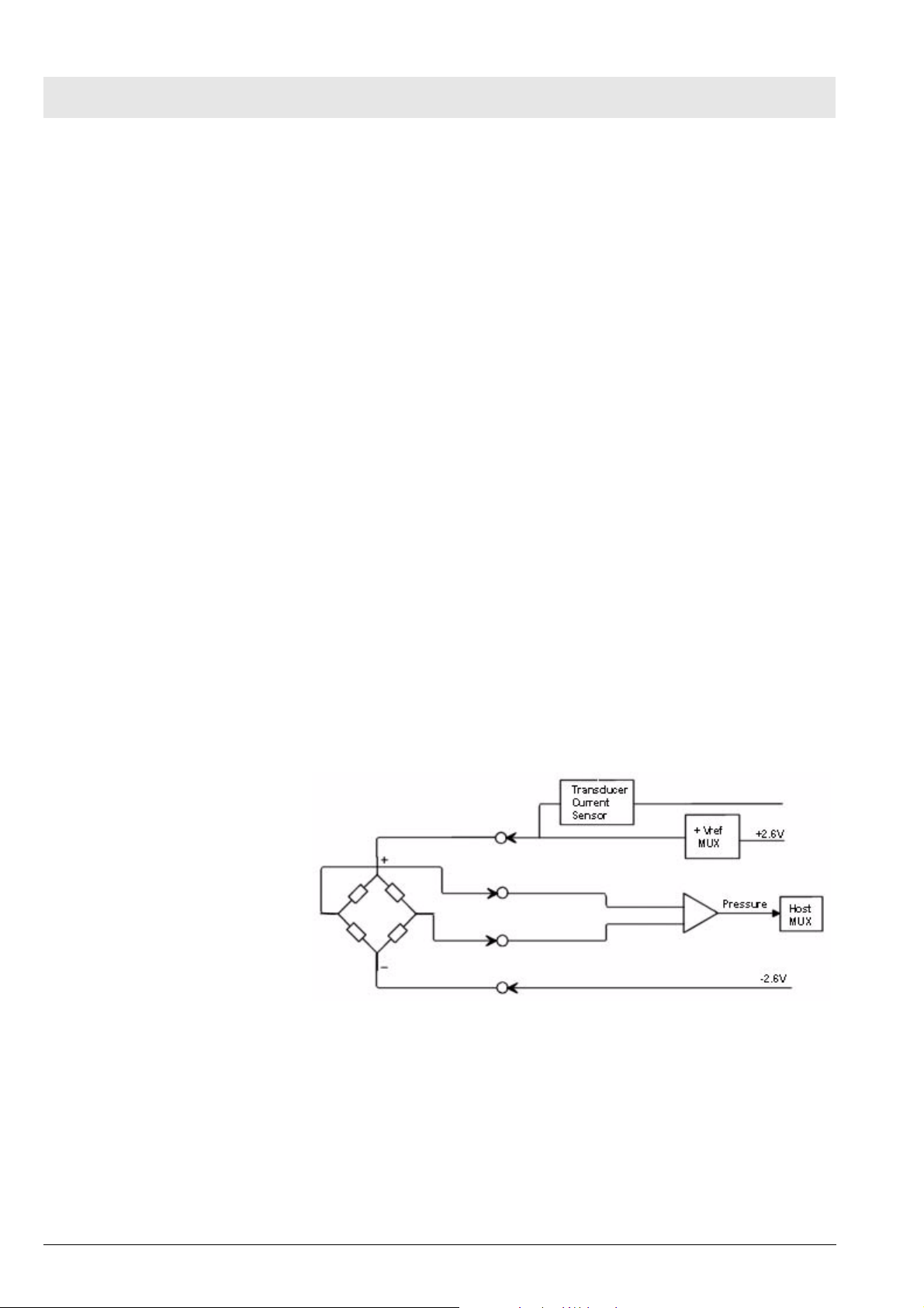
Maintenance Procedures Gamma / Gamma XL Patient Monitor
5. Clamp pneumatic hose (with hemostat or clamp) between T-connector
and monitor (1 in Figure 2) and using pressure bulb, increase pressure to
250 ±5 mmHg. Then clamp hose at inflation bulb (2 in Figure 2), and let
pressure stabilize for 1 minute. Do NOT run pump.
6. Observe pressure drop for an additional 5 minutes. Drop should be
<2 mmHg in 5 minutes. If not, tighten all connections and fittings and
retest equipment for leakage. When leakage test OK, go on to step 7.
7. With both clamps removed, reinflate to 250 ±5 mmHg, if necessary, and
then re-clamp hose at inflation bulb.
8. Observe pressure drop for 1 minute. Drop should be <4 mmHg.
• If leakage test OK, remove clamp at inflation bulb and go on to Func-
tional and Calibration Check.
• If leakage test not OK, monitor’s internal pneumatics system needs to
be serviced. Contact your Draegermedical Service Product Representative.
Functional and Calibration
Check
1.4.12 Invasive Blood Pressure
1. Using hand bulb, increase pressure to 250 ±5 mmHg, if necessary, and
allow it to stabilize for 1 minute.
2. Verify that pressure values displayed on monitor (lower left message
area) and pressure indicator are within ±3 mmHg of each other.
3. Slowly release pressure in decrements of 50 mmHg. At pressures of 200,
150, 100, and 50 mmHg, verify that pressure values on monitor and pressure indicator are within ±3 mmHg of each other at each level.
4. If NBP function fails calibration check, contact your Draegermedical Service Product Representative. Otherwise, if NBP function is OK, Set Calibration Mode to “OFF” as described in steps 3 and 4 of System Setup
Procedure above, and continue.
5. Document test results on a copy of Acceptance Test Report.
42
Figure 3 IBP Test Setup
IBP Test Setup 1. Connect simulator BP output to IBP input on monitor’s left side panel,
using adapter cable 33 68 383.
2. On MAIN Screen, select Channel 2 waveform field, and select following
on Channel 2 menu.
• Waveform - GP1
• Size - 200 mmHg
Dräger Medical AG & Co. KGaA 6013.053 Revision 0 Released
Gamma_Gamma_XL_SM_Maintenance.fm 03.12.04
All rights reserved. Copyright reserved.

Gamma / Gamma XL Patient Monitor Maintenance Procedures
3. Return to MAIN Screen.
Calibration 4. Apply a static pressure of 0 mmHg from patient simulator.
5. Select pressure parameter box.
6. Select “Zero” in IBP Setup window.
7. Verify that “GP1 Zero Accepted” exhibits in message field, and that a flat
pressure curve is displayed at 0 line in second waveform channel.
8. Change static pressure to 100 mmHg at patient simulator.
9. Select Manometer Cal. in IBP Setup window.
10. Set Manometer Cal. to 100. (Even if Manometer Cal. reads 100, select
field and reset value to 100.)
11. Verify that “GP1 Cal. Accepted” exhibits in message field simultaneously
with a tone. Return to MAIN screen.
12. Verify that Mean, Diastolic and Systolic values displayed read 100 mmHg
±2 mmHg, and that a flat pressure curve is displayed exactly in the middle of waveform channel.
13. Increase static pressure to 200 mmHg.
14. Verify that Mean, Diastolic and Systolic values displayed are 200 mmHg
±2 mmHg, and that flat pressure curve is displayed in waveform channel.
IBP Limits Alarms 15. In Alarm Limits Table select AutoSet.
16. In Alarm Limits Table set Syst/Dia/Med Alarm to ON.
17. Set simulator to stat < 50.
18. Verify that monitor responds with following Serious Alarm indications:
• Mean, Diastolic and Systolic values = simulator stat setting.
• GP1 parameter field changes to yellow.
• Serious Alarm tone sounds.
• Messages “GP1 Static”, “GP1 Dia <170” and “GP1 Mean <170”blink
on and off in message field.
19. In Alarm Limits Table set Sys/Dia/Med Alarm to OFF.
1.4.13 Leakage Current Test Gamma and Gamma XL Patient Monitors are battery operated devices, isolated from ground by the transformer in an ac power adapter, or grounded
through the IDS power supply when operated from an external ac power
source. Leakage current tests assure that under both normal and fault conditions, any leakage current does not exceed values given in Tabl e 2 . Use the
following general procedure to measure leakage currents.
Table 2 Leakage Current Tests
TEST Max. Current
Combined Lead Leakage <10µA
Individual Lead Leakage <10µA
Paired Lead Leakage <10µA
Leakage with Line Voltage on Leads <50µA
All rights reserved. Copyright reserved.
Gamma_Gamma_XL_SM_Maintenance.fm 03.12.04
Dräger Medical AG & Co. KGaA 6013.053 Revision 0 Released
43

Maintenance Procedures Gamma / Gamma XL Patient Monitor
1. Perform leakage current tests on a Gamma series monitor with ac power
adapter (see Figure 4) or IDS power supply (see Figure 5) plugged into
leakage tester.Attach MutiMed cable (1 in Figure 4 and in Figure 5) to
Monitor.Attach MutiMed cable ECG leads (2 in Figure 4 and in Figure 5)
to corresponding posts at Leakage Tester.
Figure 4 Block Diagram: Earth Leakage Current (AC/DC Power Adapter)
44
Figure 5 Block Diagram: Earth Leakage Current (Infinity Docking Station)
2. Follow leakage tester manufacturer’s instructions to measure each leakage current given in Tab l e 2 , for each of following conditions:
Dräger Medical AG & Co. KGaA 6013.053 Revision 0 Released
Gamma_Gamma_XL_SM_Maintenance.fm 03.12.04
All rights reserved. Copyright reserved.

Gamma / Gamma XL Patient Monitor Maintenance Procedures
• Combined Lead Leakage
• Individual Lead Leakage
• Paired Lead Leakage
• Leakage with Line Voltage on Leads
3. Verify that current does not exceed values shown in Ta b l e 2 .
4. Document test results on a copy of Acceptance Test Report.Disconnect
MutiMed cable ECG leads (2 in Figure 4 and in Figure 5) from corresponding posts at Leakage Tester.Short together all leads to shield at end
of PodCom Leakage Test Cable (4 in Figure 4 and in Figure 5) and connect leads and shield to RL post of Leakage Tester.Attach Pod Com
Leakage Test Cable (3 in Figure 4 and in Figure 5) to Gamma PodPort
connector.Follow leakage tester manufacturer’s instructions to measure
each leakage current given in Table 2, for each of following conditions:
• Individual Lead Leakage
• Leakage with Line Voltage on Leads
5. Verify that current does not exceed values shown in Ta b l e 2 .
6. Document test results on a copy of Acceptance Test Report.
1.5 Acceptance Test
Report
Site: ______________________________ Date: ____________
Technician: ___________________________
Location: ___________________________
Monitor Serial Number: ___________
Installed SW Version: ________
√ = Function OK
Power Circuits and Startup_____
Optical Encoder_____
TFT-LCD Display_____
Fixed Keys _____
ECG/Resp _____
Asystole_____
SpO2 _____
Temperature_____
Functional Verification_____
Calibration check (if required)_____
All rights reserved. Copyright reserved.
Gamma_Gamma_XL_SM_Maintenance.fm 03.12.04
Dräger Medical AG & Co. KGaA 6013.053 Revision 0 Released
45

Maintenance Procedures Gamma / Gamma XL Patient Monitor
Resistance
Setting (Ω)
Set Tempera-
ture
Monitor
Reading
Tolerance Pass
6990 1.0 0.9 to 1.1
3539 15.0 14.9 to 15.1
1355 37.0 36.9 to 37.1
843.2 49.0 48.9 to 49.1
etCO2 (if installed)_____
Non-Invasive Blood Pressure _____
Invasive Blood Pressure_____
Leakage Current Test_____
• Combined Lead leakage (µA)_______
• Individual Lead leakage (µA)_______
• Paired Lead leakage (µA)_______
• Leakage with Line Voltage on Leads (µA)_______
Monitor has passed all required tests.
_____________________________________ ________________
Servicing Technician Date
46
Dräger Medical AG & Co. KGaA 6013.053 Revision 0 Released
Gamma_Gamma_XL_SM_Maintenance.fm 03.12.04
All rights reserved. Copyright reserved.

Schematics and Diagrams
47

48

Gamma / Gamma XL Patient Monitor Schematics and Diagrams
Schematics and Diagrams
1 IBP Connector
Figure 1 IBP Connector (refer to Tab le 1 )
Table 1 IBP Connector Pinouts
2 MultiMed Pod Con-
nector
Temp SPO2 ECG
Pin No. Signal Pin No. Signal Pin No. Signal Pin.No. Signal
Pin No. Signal Pin No. Signal
1 +VREF 2 -VREF
5+IBP6-IBP
3, 4, 7 GND 8, 9 SHIELD
Figure 2 MultiMed Pod Connector (refer to Table 2)
Table 2 MultiMed Pod Connector Pinouts
1 TA 1 DETA 1 SHGND 2 LA
2 TB (Not Used) 2 DETK SH 3 SHGND 4 LL
3 TCOM 3 NC 5 SHGND 6 RA
4 NC 4 REDK 7 SHGND 8 V
5 NC 5 RCALRTN 9 SHGND 10 RL
6NC 6RCALIB
7NC 7IRK
All rights reserved. Copyright reserved.
Gamma_Gamma_XL_SM_Schematics_and_Diagrams.fm 03.12.04
Dräger Medical AG & Co. KGaA 6013.053 Revision 0 Released
49

Schematics and Diagrams Gamma / Gamma XL Patient Monitor
3 Docking Station
Connector
Figure 3 Docking Station Connector (refer to Table 3)
Table 3 Docking Station Connector Pinouts
Pin No. Signal Pin No. Signal
1 RCDRPWR 15 DUTX2
2 DCGND 16 DURX2
3 PTXD3 17 DCGND
4 PRXD3 18 VGARED
4 Alarm Cable (Unter-
minated)
5 DCGND 19 VGAGRN
6 EXTAUD 20 VGABLU
7 ALARM 21 DCGND
8 PSNL 22 VSYNCLB
9 DUTX1 23 HSYNCLB
10 DURX1 24 RCV-
11 DCGND 2 5 R C V+
12 DSPWR 26 TX-
13 DURTS 227 TX+
14 DUCTS2 28 SW6
50
Figure 4 SHP ACC CBL ALARM UNTERM 5M (refer to Tabl e 4 )
Table 4 Remote Alarm Cable Color Code
Connector Pin No. Relay Input Wire Color SPDT Relay Output Circuit Status
1Tan BrownRTN
2 - 8 NC Green Inactive Open
Dräger Medical AG & Co. KGaA 6013.053 Revision 0 Released
Gamma_Gamma_XL_SM_Schematics_and_Diagrams.fm 03.12.04
All rights reserved. Copyright reserved.
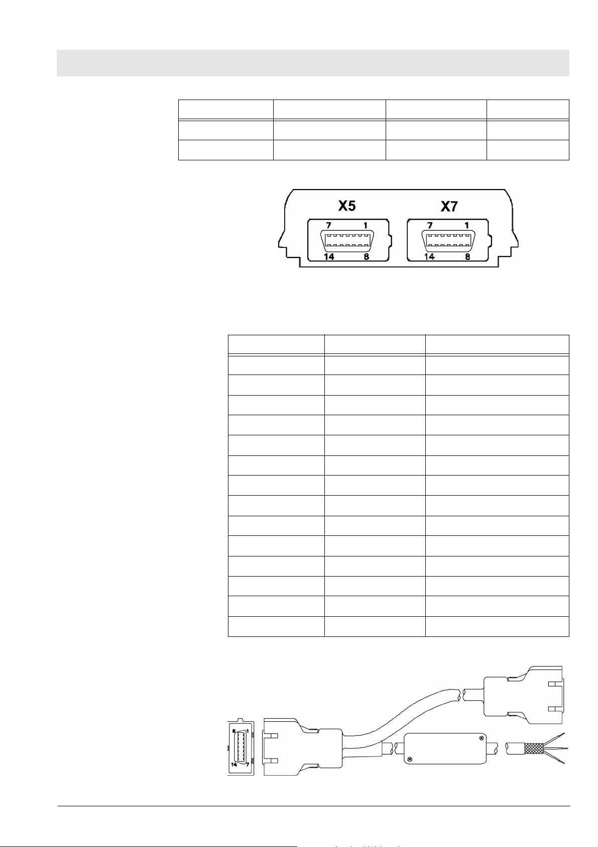
Gamma / Gamma XL Patient Monitor Schematics and Diagrams
Connector Pin No. Relay Input Wire Color SPDT Relay Output Circuit Status
9 Orange White Inactive Closed
10 - 14 NC
5 Interface Plate Con-
nector
Figure 5 Interface Plate Connector (refer to Tab l e 5 )
Table 5 Interface Plate Connectors Pinouts
Pin No CRT - X5 Recorder/Alarm - X7
1 Ext Red GND
2 VGND +12VDC
3 Ext Grn Rec Tx
4 VGND +12VDC
5 Ext Blu Diag Tx
6 VGND +12VDC
7 GND Rec RTS
8 H Sync Rec CTS
9 V Sync Alarm Out
10 Rem TxD Rec GND
11 Rem RxD Rec GND
12 Power Switch Rec Rx
13 Rem Audio Rec GND
14 Rem Audio Ret Diag Rx
6 Recorder/Alarm Y-
cable
All rights reserved. Copyright reserved.
Gamma_Gamma_XL_SM_Schematics_and_Diagrams.fm 03.12.04
Dräger Medical AG & Co. KGaA 6013.053 Revision 0 Released
Figure 6 SHP ACC CBL Y RECORDER/ALARM (refer to Tab le 6)
51
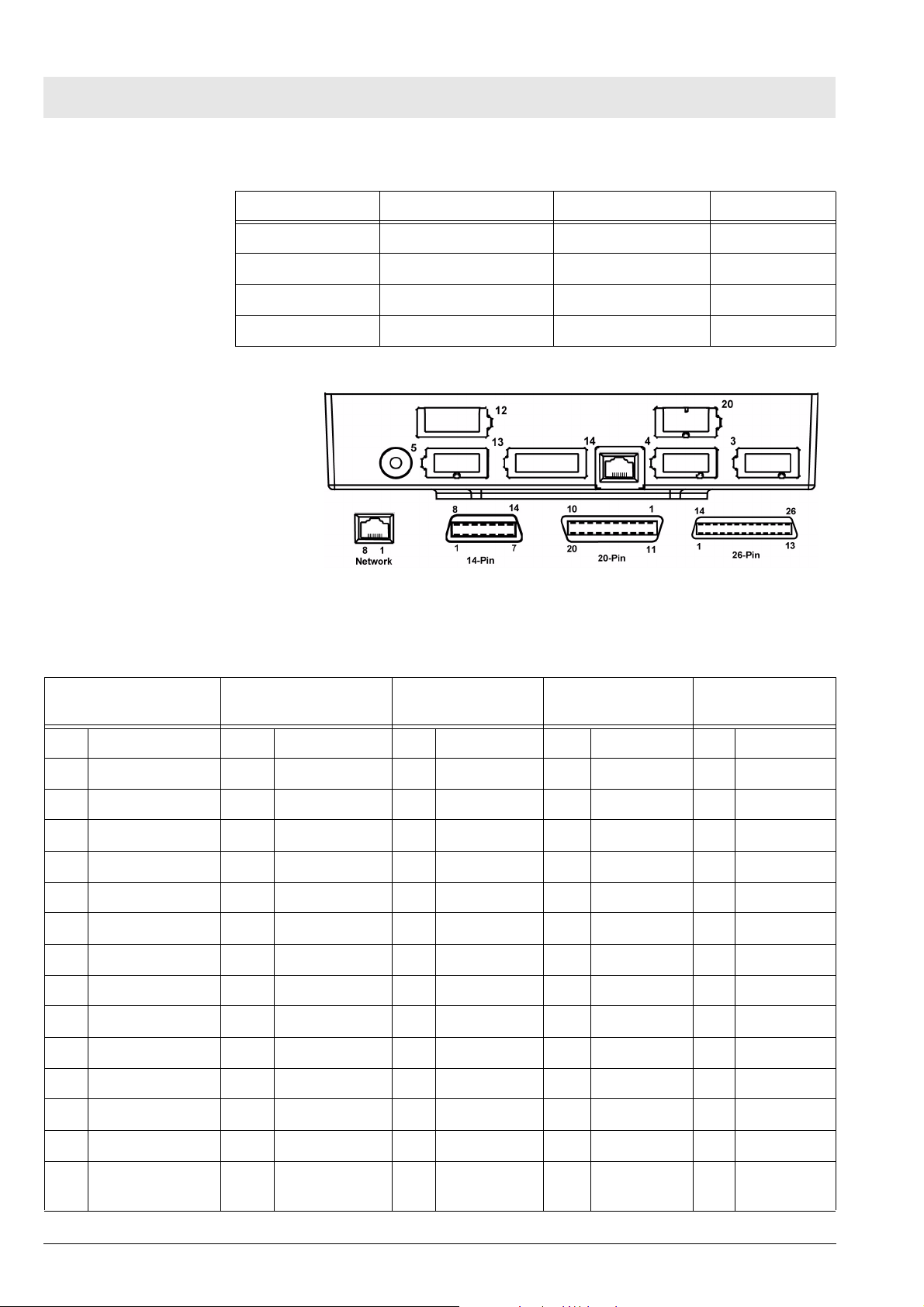
Schematics and Diagrams Gamma / Gamma XL Patient Monitor
Table 6 Remote Alarm Cable Color Code
Connector Pin No. Relay Input Wire Color SPDT Relay Output Circuit Status
1Tan BrownRTN
2 - 8 NC Green Inactive Open
9 Orange White Inactive Closed
10 - 14 NC
7 Infinity Docking Sta-
tion Connectors
Figure 7 Infinity Docking Station Connectors (refer to Table 7)
Table 7 Infinity Docking Station Connectors
ALM/KB/DIAG/COMM
-1 (X4)
Pin Signal Pin Signal Pin Signal Pin Signal Pin Signal
1 GND 1 GND 1 Ext Red 1 MIB1 D+ 1 R50A TxD
2 Tx Data KB 2 Tx Data KB 2 VGND 2 MIB1 Pwr 2 AUX Pwr2
3 Rem Kbd Pwr 3 Rem Kbd Pwr 3 Ext Grn 3 MIB1 D- 3 R50A RxD
4 ISD Power 4 ISD PWR 4 VGND 4 MIB2 Pwr 4 AUX Pwr2
5 Diag TxD (CPS) 5 Diag TxD 5 Ext Blu 5 MIB1 S+ 5 R50A CTS
6 DEBUG1 6 MCBOOTL 6 VGND 6 CAN+ 6 AUX Pwr2
7 ISD GND 7 ISD GND 7 GND 7 MIB1 S- 7 R50A RTS
8 RxData KB 8 RxData KB 8 H-Sync 8 CAN RL 8 AUX Pwr2
9 Alarm Out 9 Alarm Out 9 V-Sync 9 AUX1 ID0 9
ALM/KB/DIAG/COMM
-2 (X3)
External CRT (X5) AUX/MIB/CAN-
BUS(X12)
Recorder (X13)
10 GND 10 GND 10 Remote TxD 10 AUX1 ID1 10 AUX Pwr2
11 HWBootL 11 NMI 11 Remote RxD 11 AUX1 ID2 11 AUX2 ID0
12 COMM-1 Rx 12 COMM-2 Rx 12 Pwr Switch 12 MIB2 D+ 12 AUX2 ID1
13 COMM-1 Tx 13 COMM-2 Tx 13 Rem Audio 13 GND 13 AUX2 ID2
14 Diag RxD 14 Diag RxD 14 Rem Aud
Ret
52
Dräger Medical AG & Co. KGaA 6013.053 Revision 0 Released
14 MIB2 D- 14 AUX2 P
Enb
Gamma_Gamma_XL_SM_Schematics_and_Diagrams.fm 03.12.04
All rights reserved. Copyright reserved.

Gamma / Gamma XL Patient Monitor Schematics and Diagrams
ALM/KB/DIAG/COMM
-1 (X4)
PSL (X20) Network (X14) 17 GND 17 P GND
Pin Signal Pin Signal 18 MIB2 S- 18 R100A
1 GND 1 Tx+ 19 CANBUS+ 19 P GND
2 PWR 2 Tx- 20 Chassis
ALM/KB/DIAG/COMM
-2 (X3)
3 Rx+ 21 P GND
6 Rx- 22 R100 RxD-
External CRT (X5) AUX/MIB/CAN-
BUS(X12)
15 GND 15 P GND
16 MIB2 S+ 16 R100A
GND
Recorder (X13)
TxD+
TxD-
20 R100A
RxD+
23 P GND
24
25 Chassis
GND
8 PodPort Connector
Pins
26 Chassis
GND
Figure 8 PodPort Connector Pins
Table 8 PodPort Connector Pinouts
Pin No. Signal
1 TXDATA+
2NC
3 TXDATA-
4RXDATA+
5 POD GND
6 POD PWR
All rights reserved. Copyright reserved.
Gamma_Gamma_XL_SM_Schematics_and_Diagrams.fm 03.12.04
Dräger Medical AG & Co. KGaA 6013.053 Revision 0 Released
53

Schematics and Diagrams Gamma / Gamma XL Patient Monitor
Pin No. Signal
7 RXDATA-
8,9 POD1 SHD
54
Dräger Medical AG & Co. KGaA 6013.053 Revision 0 Released
Gamma_Gamma_XL_SM_Schematics_and_Diagrams.fm 03.12.04
All rights reserved. Copyright reserved.

Fault-Cause-Remedy
55

56

Gamma / Gamma XL Patient Monitor Fault_Cause_Remedy
Fault-Cause-Remedy
1 Troubleshooting If the Monitor should fail to respond properly to procedures prescribed in the
User Guide for the installed software version, use the procedures below to
aid in identifying and remedying the problem.
1.1 Power Problems
1.1.1 No Response When
POWER ON/OFF Key
Pressed
Conditions Possible Cause(s) Troubleshooting and Remedial Action
Monitor connected
directly to Power
Adapter; Battery
Charger LED not illuminated*
Monitor on docking
station; Battery charger
LED not illuminated
Power Adapter malfunction
Monitor Malfunction
IDS Power Supply malfunction
CPS/IDS malfunction
Monitor malfunction
There are several possible reasons why a Monitor might not respond when
the Power ON/OFF key is pressed. Required troubleshooting procedures
depend on power sources connected to the monitor. Refer to Table 1.
Table 1 Power-On Problems
1. Assure Power Adapter is connected to an active
hospital power source.
2. Disconnect power adapter from Monitor and measure Power Adapter output voltage.
• If voltage = 11.6 to 13.8 VDC, continue to step 3.
• If voltage < 11.6 VDC or > 13.8 VDC, replace
Power Adapter and recheck Battery Charger
LED. If problem persists, continue to step 3.
3. Contact your Dräger Medical service representative.
1. Check for a or b below.
a) If IDS, assure that IDS power supply is con-
nected to active hospital power source.
b) If CPS, assure that CPS is connected to active
hospital power source and switched ON.
2. If CPS or IDS power supply LED not illuminated,
check power source and power cable. If O.K.,
replace CPS or IDS power supply, and recheck CPS
or IDS power supply LED. If condition persists, continue to step 3.
3. Measure voltage between pins 11 and 12 at docking
connector on docking station. (See figure inset at left
for pin locations on docking connector.)
• If voltage = 11.6 to 13.8 VDC, continue to step 4.
• If voltage ≤11.6 VDC or ≥13.8 VDC, replace IDS
Power Supply or CPS. If problem persists, continue to step 4
4. Contact your Dräger Medical service representative.
Monitor on docking
station or directly connected to Power
Adapter; Battery
charger LED illuminated
All rights reserved. Copyright reserved.
Gamma_Gamma_XL_SM_Fault_Cause_Remedy.fm 03.12.04
Dräger Medical AG & Co. KGaA 6013.053 Revision 0 Released
Corrupted Software
Front Bezel malfunction
Front Panel PCB malfunction
Main Processor malfunction
1. Press Power On key to power monitor ON.
2. Try booting with monitor software PCMCIA card
inserted into card slot.
3. Contact your Dräger Medical service representative.
57

Fault_Cause_Remedy Gamma / Gamma XL Patient Monitor
Conditions Possible Cause(s) Troubleshooting and Remedial Action
NO power. Monitor not
connected to AC
Power Adapter or
docking station; battery
installed
Battery discharged or needs
to be replaced
Battery charger circuitry malfunction
1. Connect monitor to AC Power Adapter or Docking
Station.
2. When Battery charger LED illuminates, press
POWER ON/OFF key to power monitor ON and
access MAIN screen. (If Battery charger LED fails to
illuminate, refer to section above on Condition “Monitor connected directly to Power Adapter; Battery Charger LED not illuminated or “Monitor on
docking station; Battery charger LED not illuminated.”)
3. Allow monitor or remain on Power Adapter or powered Docking Station for ≈1 hr. Disconnect monitor
from Power Adapter or powered Docking Station.
After ≈30 sec. check battery level bar graph, located
at bottom left side of display, and verify that a portion
of the bar graph is green.
• If a portion of the bar graph is green, reconnect
monitor to Power Adapter or powered Docking
Station. Leave monitor connected an additional
4.5 hrs for Lead-acid type battery or 7 hrs for an
optional Lithium-ion type battery, then go to step
4.
• If no portion of the bar graph is green, replace
main battery, and then repeat step 3. If charge
level remains constant, go to step 5.
4. After charging the Main battery (≥4.5 hrs for Leadacid type battery or ≥7 hrs for optional Lithium-ion
type battery) recheck battery charge level.
5. If charge level = 100%, return monitor to clinical service.
6. If charge level <100% replace Main battery.
7. If problem persists with new main battery, contact
your Dräger Medical service representative.
1.1.2 Power On/Off Piezo Tone
Table 2 Power-off Alarm Malfunction
Fails to Sound
Symptom(s) Possible Cause(s) Troubleshooting and Remedial Action
Piezo tone fails to
Front Panel PCB malfunction
1. Contact your Dräger Medical service representative.
sound when monitor
powered on, if monitor
Main Processor malfunction
loses power, or when
monitor powered-off.
58
Dräger Medical AG & Co. KGaA 6013.053 Revision 0 Released
Gamma_Gamma_XL_SM_Fault_Cause_Remedy.fm 03.12.04
All rights reserved. Copyright reserved.

Gamma / Gamma XL Patient Monitor Fault_Cause_Remedy
1.1.3 Power-up Sequence
Fails To complete Properly
Symptom(s) Possible Cause(s) Troubleshooting and Remedial Action
Power inputs all OK but
monitor fails to complete power-up
sequence
Software program corrupted
Main PCB malfunction
1.2 Optical Encoder Mal-
Table 3 Power-up Process Malfunction
If power ON LED illuminates but monitor fails to complete
power-up sequence, reinstall software as follows:
1. With monitor powered off, insert PCMICA card into
slot at right side of monitor.
2. Power monitor on.
3. If problem persists, contact your Dräger Medical service representative.
Table 4 Rotary Knob Malfunction
function
Symptom(s) Possible Cause(s) Troubleshooting and Remedial Action
Rotary knob fails to
properly select fields, or
pressing the knob in fails
to activate a menu or
select a default.
Front Panel PC Board malfunction
Optical Encoder malfunction
Contact your Dräger Medical service representative.
Main Processor malfunction
1.3 TFT-LCD Display
Table 5 LCD Display Malfunction
Malfunction
Symptom(s) Possible Cause(s) Troubleshooting and Remedial Action
>17 inoperative pixels
(“stuck” ON or OFF).
Areas of display missing
or color contaminated
Backlight fails to provide
sufficient and consistent
background illumination
for the LCD display.
LCD screen malfunction Contact your Dräger Medical service representative.
Front Panel PC Board
malfunction
Processor on Main PCB
malfunction
TFT-LCD Display malfunction
Inverter malfunction
Front Panel PC Board
malfunction
Contact your Dräger Medical service representative.
Contact your Dräger Medical service representative.
Main Processor malfunction
All rights reserved. Copyright reserved.
Gamma_Gamma_XL_SM_Fault_Cause_Remedy.fm 03.12.04
Dräger Medical AG & Co. KGaA 6013.053 Revision 0 Released
59

Fault_Cause_Remedy Gamma / Gamma XL Patient Monitor
1.4 Fixed Key Fails to
Table 6 Fixed Key Malfunction
Function
Symptom(s) Possible Cause(s) Troubleshooting and Remedial Action
A Fixed Key fails to initiate change
Front Bezel malfunction
Front Panel PC Board malfunction
Main Processor malfunction
1.5 Visual or Audible
Table 7 Alarm Malfunctions
Contact your Dräger Medical service representative.
Alarm Reporting
Failure
Symptom(s) Possible Cause(s) Troubleshooting and Remedial Action
Audible Alarm O.K.,
but Visual Alarm Fails.
Visual Alarm O.K., but
Audible Alarm Fails.
Software problem 1. Try reinstalling software.
2. If problem persists, contact your Dräger Medical service
representative.
Speaker malfunction
Front Panel PC Board
malfunction
Main Processor malfunction
1. Power-cycle monitor and listen for tone after icon
appears on power-up screen (not the piezo, which
sounds before the icon appears).
2. If tone fails to sound, replace speaker.
3. If problem persists, contact your Dräger Medical service
representative.
1.6 NBP Malfunction Table 8 NBP Malfunctions
Symptom(s) Possible Cause(s) Troubleshooting and Remedial Action
NBP fails to zero properly, fails characterization, or fails calibration
check
NBP pump fails to
start/stop when NBP
key on front panel is
pressed
NBP pneumatic system
malfunction
Main Processor malfunction
Front Bezel malfunction
Front Panel PC Board
malfunction
NBP pump subassembly
malfunction
Main Processor malfunction
Contact your Dräger Medical service representative.
1. If monitor reporting NBP in fault mode, or error message
displays, power-cycle monitor.
2. If problem persists, contact your Dräger Medical service
representative.
60
Dräger Medical AG & Co. KGaA 6013.053 Revision 0 Released
Gamma_Gamma_XL_SM_Fault_Cause_Remedy.fm 03.12.04
All rights reserved. Copyright reserved.

Gamma / Gamma XL Patient Monitor Fault_Cause_Remedy
Symptom(s) Possible Cause(s) Troubleshooting and Remedial Action
NBP pump starts, but
cuff fails to inflate
/ deflate properly
Cuff assembly malfunction
NBP pneumatic system
malfunction
1. Recheck cuff assembly and installation, and replace cuff
assembly if defective.
2. If problem persists, check NBP tubing in rear housing of
monitor.
3. If tubing OK, contact your Dräger Medical service representative.
1.7 etCO2 Malfunction Table 9 etCO2 Malfunctions
Symptom(s) Possible Cause(s) Troubleshooting and Remedial Action
Parameter box fails to
appear when sensor
plugged into pod
Sensor fails calibration
Persistent Adapter
Failure message
Sensor or cable malfunction
etCO2 Pod malfunction
PodPort PC Board malfunction
Main Processor malfunction
Airway adapter or sensor
window occluded
Airway adapter malfunction
1. Replace etCO2 Sensor.
2. If problem persists, replace etCO2 Pod.
3. If problem persists, contact your Dräger Medical service
representative.
1. If adapter or sensor window occluded, clean window.If
problem persists, replace airway adapter.If problem persists, replace sensor.If problem persists, replace etCO2
Pod.If problem persists, contact your Dräger Medical service representative.
Sensor malfunction
All rights reserved. Copyright reserved.
Gamma_Gamma_XL_SM_Fault_Cause_Remedy.fm 03.12.04
Dräger Medical AG & Co. KGaA 6013.053 Revision 0 Released
61

Fault_Cause_Remedy Gamma / Gamma XL Patient Monitor
1.8 No Printout from
Table 10 Recorder Problems
Recorder
Symptoms Possible Cause(s) Troubleshooting and Remedial Action
Recorder Power LED
NOT illuminated
when Record key
depressed
Recorder malfunction
Cabling malfunction
Interface Plate (if
installed) malfunction
CPS / IDS (if installed)
malfunction
Main Processor malfunction
1. Assure that all units in the power chain are properly connected and powered ON.
2. If problem persists do either a or b. Refer to illustrations
below left.
a) If Recorder has installed Interface Plate, detach Inter-
face Plate from Recorder, depress Record key at monitor and check voltage between pins 1 and 2 on
Interface Plate docking connector.
b) If Recorder mounted on Auxiliary Docking Station,
depress Record key and check voltage between pins 1
and 2 on Auxiliary Docking Station connector.
3. If voltage O.K., replace Recorder.
4. If voltage NOT O.K., check for +12VDC between pins 1
and 2 on monitor docking connector.
• If voltage O.K., check for +12VDC between pins 1 and
2 of all docking connectors in path between monitor
and recorder, and between pins 2 and 15 of X13 on
CPS or IDS. Replace component that fails to provide
12VDC at the appropriate pins.
• If voltage not O.K. on monitor docking connector, con-
tinue.
5. If problem persists, replace Recorder.
6. If problem persists, contact your Dräger Medical service
representative.
Local Recorder connected directly to
Monitor in standalone configuration
62
Dräger Medical AG & Co. KGaA 6013.053 Revision 0 Released
Recorder malfunction
Interconnecting cable or
connection malfunction
Recorder or Monitor Interface Plate malfunction
Main Processor PCB malfunction
1. With an ECG waveform from patient simulator on Monitor
display, press Record key.
2. If “Recording Started” followed by double-tone, then
“Recording Stored” message appears in the message
field, continue to step 2.
3. If no message or recording appears, go to step 5.
4. If problem persists, and Recorder Cable Art. No. 43 18
130 E530U is installed, replace Recorder cable.
5. If problem persists, and separate Interface Plates and
Recorder cable are installed, replace each item one at a
time to isolate possible malfunction.
6. If problem persists, replace Recorder.
7. If problem persists, contact your Dräger Medical service
representative.
Gamma_Gamma_XL_SM_Fault_Cause_Remedy.fm 03.12.04
All rights reserved. Copyright reserved.

Gamma / Gamma XL Patient Monitor Fault_Cause_Remedy
Symptoms Possible Cause(s) Troubleshooting and Remedial Action
Local Recorder connected to Monitor
through CPS or IDS
Recorder malfunction
CPS/IDS - Recorder
cable malfunction
Recorder Interface Plate
malfunction
CPS or IDS malfunction
Docking Station or CPS
Bridge Plate malfunction
Main Processor malfunction
1.9 Isolating Cable Malfunctions
1. With an ECG waveform from patient simulator on Monitor
display, press Record key.
2. If “Recording Started” followed by double-tone, then
“Recording Stored” message appears in the message
field, check cables and connections between Monitor,
CPS/IDS, and Recorder, then continue to step 5.
3. If no message or recording appears, go to step 4.
4. Substitute Recorder connection by installing Recorder
cable, 47 21 770 or 43 13 560, in place of Docking Station,
CPS/IDS, and cabling.
5. If problem persists, replace Recorder.
6. If problem disappears, replace each component bypassed
by Recorder cable, to isolate source of problem and
replace malfunctioning component.
7. If problem persists, contact your Dräger Medical service
representative.
A general troubleshooting and repair approach for cable malfunctions is to
use a known input signal for any given parameter, and then replace a cable or
sensor found to be malfunctioning. Cable malfunctions, including those associated with connectors on the cables, fall into one of three categories -- Open
circuits, Short circuits, and Intermittent conditions
1.10 Patient-Related Data
Not Retained or
Monitor Fails to
Compute Trends
Open circuits and short circuits manifest themselves as a loss of signal. Software in the Monitor senses the loss, and generates an error message such
as “ECG Leads Off” and “SpO2 Transparent.” Typically, short circuits result in
software resets.
An intermittent condition (e.g. ECG lead not making good skin contact) may
manifest itself as noise displayed at the monitor screen. A source of ECG
noise can often be isolated by removing the signal and shorting all ECG leads
together. Then flex along the cable, particularly at connectors, while watching
for noise indications on the monitor display.
Contact your Dräger Medical service representative.
All rights reserved. Copyright reserved.
Gamma_Gamma_XL_SM_Fault_Cause_Remedy.fm 03.12.04
Dräger Medical AG & Co. KGaA 6013.053 Revision 0 Released
63

Fault_Cause_Remedy Gamma / Gamma XL Patient Monitor
64
Dräger Medical AG & Co. KGaA 6013.053 Revision 0 Released
Gamma_Gamma_XL_SM_Fault_Cause_Remedy.fm 03.12.04
All rights reserved. Copyright reserved.

Annex
Spare parts list
Test List
Problem Report
65

66

Gamma and Gamma XL Patient Monitors Spare Parts List
1 Spare Parts List
Table 1 Gamma and Gamma XL - Replaceable Parts and Subassem-
blies
Part Description Part No.
(English Label Pictured)
Language Label GAMMA XL DA 8in
Language Label GAMMA XL DE 8in
Language Label GAMMA XL EN 8in
Language Label GAMMA XL ES 8in
Language Label GAMMA XL FR 8in
Language Label GAMMA XL IT 8in
Language Label GAMMA XL NL 8in
Language Label GAMMA XL NO 8in
Language Label GAMMA XL PO 8in
Language Label GAMMA XL RU 8in
Language Label GAMMA XL SV 8in
Language Label GAMMA XL TR 8in
Language Label GAMMA DA 6in
MS13768
MS13769
MS13770
MS13777
MS13771
MS13772
MS13773
MS13774
MS13775
MS13776
MS13778
MS13779
MS14496
(English Label Pictured)
Language Label GAMMA DE 6in
Language Label GAMMA EN 6in
Language Label GAMMA ES 6in
Language Label GAMMA FR 6in
Language Label GAMMA IT 6in
Language Label GAMMA JA 6in
Language Label GAMMA NL 6in
Language Label GAMMA NO 6in
Language Label GAMMA PO 6in
Language Label GAMMA RU 6in
Language Label GAMMA SV 6in
Language Label GAMMA TR 6in
MS14497
MS14498
MS14509
MS14499
MS14500
MS14501
MS14502
MS14503
MS14504
MS14505
MS14506
MS14507
Gamma_Gamma_XL_IEC_Spare_Parts_List.fm 03.12.04
All rights reserved. Copyright reserved.
Dräger Medical AG & Co. KGaA 6013.053 Revision 0 Released
1

Spare Parts List Gamma and Gamma XL Patient Monitors
Part Description Part No.
Bezel Lens GAMMA XL 8in MS13758
Bezel Lens GAMMA 6in MS14510
Optical Encoder 4311622
Rotary Knob DELTA GAMMA XL MS13765
Gamma_Gamma_XL_IEC_Spare_Parts_List.fm 03.12.04
All rights reserved. Copyright reserved.
2
Dräger Medical AG & Co. KGaA 6013.053 Revision 0 Released

Gamma and Gamma XL Patient Monitors Spare Parts List
Part Description Part No.
LCD SC 6802XL 8.4in 7870780
Display LCD SC 6002XL 6.5in 5950790
Backlight GAMMA XL 7869444
Backlight SC 6002XL 6.5in 7258945
Gamma_Gamma_XL_IEC_Spare_Parts_List.fm 03.12.04
All rights reserved. Copyright reserved.
Dräger Medical AG & Co. KGaA 6013.053 Revision 0 Released
3

Spare Parts List Gamma and Gamma XL Patient Monitors
Part Description Part No.
Board Front Pnl GAMMA XL A200 MS13757
Board DCAC CONV SC 6802XL 7869329
Board Inverter SC 6002XL 5950808
Board PodCom SC 6002XL A140 5741959
Gamma_Gamma_XL_IEC_Spare_Parts_List.fm 03.12.04
All rights reserved. Copyright reserved.
4
Dräger Medical AG & Co. KGaA 6013.053 Revision 0 Released

Gamma and Gamma XL Patient Monitors Spare Parts List
Part Description Part No.
Intermediate Wall GAMMA XL
Int Wall GAMMA (for GAMMA w/o
MS13766
MS14511
podport)
Speaker SC 6002XL 5947218
Gamma_Gamma_XL_IEC_Spare_Parts_List.fm 03.12.04
PCB Processor SC 6X02XL A104 MS14350
Manifold NP SC 6002XL 5950782
All rights reserved. Copyright reserved.
Dräger Medical AG & Co. KGaA 6013.053 Revision 0 Released
5

Spare Parts List Gamma and Gamma XL Patient Monitors
Part Description Part No.
NBP Filter (Pkg of 10) 2866726
Panel Right GAMMA XL MS13762
Panel Left GAMMA XL MS13761
Button ram card DELTA GAMMA MS13760
Handle GAMMA XL MS13767
6
Dräger Medical AG & Co. KGaA 6013.053 Revision 0 Released
Gamma_Gamma_XL_IEC_Spare_Parts_List.fm 03.12.04
All rights reserved. Copyright reserved.

Gamma and Gamma XL Patient Monitors Spare Parts List
Part Description Part No.
Cbl Harness Battery GAMMA/XL MS14575
Battery Latch SC 5/600XX 3379943
Lead-Acid Battery 5947697
Lithium-Ion Battery 5732354
Battery Cover GAMMA XL MS13759
Gamma_Gamma_XL_IEC_Spare_Parts_List.fm 03.12.04
All rights reserved. Copyright reserved.
Dräger Medical AG & Co. KGaA 6013.053 Revision 0 Released
7

Spare Parts List Gamma and Gamma XL Patient Monitors
Part Description Part No.
Rear Chassis GAMMA XL MS13764
Plate Retainer GAMMA XL MS13763
Funnel SC 6002XL 5741033
Not Pictured Foot Pads (Pkg of 12) 4311374
8
Dräger Medical AG & Co. KGaA 6013.053 Revision 0 Released
Gamma_Gamma_XL_IEC_Spare_Parts_List.fm 03.12.04
All rights reserved. Copyright reserved.

Gamma / Gamma XL Patient Monitor Test List
Test List
1 Functional Verifica-
tion Tests
1.1 Power Circuits and
Startup
AC Power Adapter 1. With power cord connected to a hospital-grade power source, plug ac
Power-Up Sequence 3. Press ON/OFF switch on front panel, and verify following sequence of
Complete the following Functional Verification Tests. Document test results
on a copy of the Test List Report.
The following procedures check the monitor’s power circuits, power-up
sequence, and power off indicator. Begin this procedure with monitor turned
off, main battery removed, and ac power adapter disconnected.
power adapter into monitor.
2. Verify that green Battery Charger LED on front panel of monitor illuminates.
events:
a) Power ON LED in ON/OFF key turns on, display illuminates and mon-
itor emits a brief tone.
b) Startup screen containing displays character changing colors as it
descends towards Dräger Medical Logo.
c) Monitor emits a brief tone and screen goes blank for a few seconds.
d) Pressure relief valve pulses.
e) Display reappears containing copyright notice, installed software ver-
sion, and message “Loading software, please wait...”.
f) MAIN screen replaces Startup Screen after several seconds.
Power Off Indicator 4. Press ON/OFF switch, and verify that monitor powers-down and a high
pitched tone sounds for ≈ 7 seconds.
5. Disconnect external power source from monitor, and verify that Battery
Charger LED turns off.
Battery and Charging Circuit
6. Install main battery.
Note
Battery should have at least 50% charge level, as indicated by the charge
level bar graph in the display message area.
7. Press ON/OFF switch on front panel, and verify the following:
• Monitor powers-up according to normal power-up sequence of
events. (Refer to power-up sequence in step 3.)
• Battery charge level indicator appears in message field on bottom left
hand side of display.
8. Plug in ac power adapter, and verify that the Green Battery Charger LED
on front panel of monitor illuminates, screen brightness increases, and
after ≈ 14 seconds, charge level indicator disappears.
1.2 Optical Encoder The Rotary Knob on the front panel controls an optical encoder for pointing to
and selecting fields and functions on the display.
All rights reserved. Copyright reserved.
Gamma_Gamma_XL_SM_IEC_Test_List.fm 03.12.04
Dräger Medical AG & Co. KGaA 6013.053 Revision 0 Released
1

Test List Gamma / Gamma XL Patient Monitor
1. After power-up sequence has completed, press Rotary Knob and verify
that fill color of New Patient NO prompt changes to white indicating that
you can now confirm value NO or change it to YES.
2. Turn knob one notch (detent, click) in either direction, and verify that
value in NO field changes to YES. Turn knob another notch, and verify
that value changes back to NO.
3. Choose YES, and verify that New Patient prompt disappears.
1.3 TFT-LCD Display The Gamma Patient Monitor display is composed of an active-matrix, 6.5
inch TFT-LCD screen with backlite. The Gamma XL Patient Monitor display is
composed of an active-matrix, 8.3 inch TFT-LCD screen with backlite. Test
the TFT-LCD display as follows:
1. Verify that backlite provides sufficient and consistent background illumination for TFT-LCD.
2. Verify that there are ≤17 inoperative pixels (“stuck” ON or OFF).
1.4 Fixed Keys The following tests verify that membrane switches on the front panel are func-
tioning properly, and that the signal from the key is processed by the Front
Panel Control PCB.
Note
Before beginning Key tests access Main menu. Select Monitor Setup →
Monitor Options → Speaker Volumes, and assure that Attention Tone Volume is set to other than OFF.
ON/OFF Key The ON/OFF key initiates the power-on sequence if the monitor is powered
off, and powers-off the monitor, initiating a brief power-off piezo alarm, if the
monitor is powered-on.
Note
This test can be omitted if the procedure in step 3 of Section 1.1 Power Cir-
cuits and Startup has already been performed.
1. Press and momentarily hold ON/OFF key.
2. Verify that powered state of monitor changes from ON to OFF or from
OFF to ON.
3. Set monitor to powered-on state, if monitor powered off.
Main Screen and Menu
Keys
The Main Screen key sets the display to the MAIN screen.
4. Press Menu key to display Main menu.
5. Press Main Screen key, and verify that Main menu extinguishes, and display returns to MAIN screen.
2
Alarm Silence Key The Alarm Silence key silences an alarm tone for one minute.
6. Assure that HR alarm is enabled, and without any input applied to MultiMed POD, plug MultiMed or MultiMed 6 cable into monitor. Monitor
should Alarm.
7. Press Alarm Silence key and verify that alarm ceases.
Dräger Medical AG & Co. KGaA 6013.053 Revision 0 Released
Gamma_Gamma_XL_SM_IEC_Test_List.fm 03.12.04
All rights reserved. Copyright reserved.

Gamma / Gamma XL Patient Monitor Test List
Alarm Limits Key The Alarm Limits fixed key calls up a setup table on which upper and lower
alarm limits for physiologic parameters can be assigned, and alarms and
alarm recordings can be enabled or disabled.
8. Attach patient simulator to MultiMed cable and set simulator as follows:
• ECG = Normal Sinus
• HR = 60 beats per minute (bpm)
9. With MAIN screen displayed, press Alarm Limits fixed key.
10. Verify that Alarms Setup Table displays.
11. Set Upper HR alarm parameter to 55.
All Alarms Off Key The All Alarms Off key silences all alarms for a period of 3 minutes.
12. When alarm sounds (setup in previous step), press All Alarms Off key.
13. Verify message “All Alarms Off” appears on display.
14. Verify that after 3 minutes, alarm sounds and “All Alarms Off”message
disappears.
15. Set alarm parameter within alarm condition (Q 60).
Record Key The Record key initiates a recording when monitor is connected, either
directly or via a network, to an R50 Recorder and otherwise initiates a stored
recording.
16. Press Record key.
17. Verify “Recording Started” appears in message field.
NBP Start/Stop Key The NBP Start/Stop key initiates or terminates the inflation cycle for the non-
invasive blood pressure monitor function.
18. Press Menu key. Access Monitor Setup → Monitor Options → Speaker
Volume → Medium.
19. Press NBP Start/Stop key.
20. Verify that monitor sounds a tone. (Cuff must Not be plugged into cuff
connector.)
Fast Access Key The Fast Access key allows access to the monitor’s bottom channel menu as
well as tabular trends, graphical trends and Event recall screen.
21. Press Fast Access key, Access Bottom Channel, then select All.
22. Verify that parameter boxes appear across bottom of display.
23. Access Bottom Channel → NBP.
24. Verify NBP parameter boxes across bottom of display.
25. Access Bottom Channel → Waveform.
26. Verify that 4th channel waveform is displayed.
Note:
A 4th display channel is standard in Gamma XL monitors, and available as
a option for Gamma monitors.
27. Access Trend graphs, then press rotary knob.
28. Verify that Trend Tables appear on display.
29. Access Trend Tables, then press rotary knob.
All rights reserved. Copyright reserved.
Gamma_Gamma_XL_SM_IEC_Test_List.fm 03.12.04
Dräger Medical AG & Co. KGaA 6013.053 Revision 0 Released
3

Test List Gamma / Gamma XL Patient Monitor
30. Verify that Trend Tables appear on display.
31. Access Event Recall, then press rotary knob.
32. Verify that Event Recall screen appears on display.
1.5 ECG/RESP 1. Connect either a 3-lead, 5-lead, or 6-lead ECG cable from the Patient
Simulator into the MultiMed POD.
ECG/RESP Test Setup 2. Select HR parameter box and press rotary knob in to bring up ECG
menu.
3. Set all ECG Lead settings at default values and remaining parameters as
follows:
• Tone Source ECG
• Tone Volume Low
• Pacer Detection On
•QRS Marks On
• ECG Processing ECG1
• ECG Leads (set for type cable installed in step 1)
• Arrhythmia On
• Relearn depress knob to update Arrhythmia
4. Set simulator as follows:
• ECG = Normal Sinus
• HR = 80 beats per minute (bpm)
• amplitude = 1.0 mV
• RESPIRATION = Normal Rest.
• rate = 20 breaths per minute (BPM)
• ohms = 1.0
• LEAD SELECT = II/RL-LL
• BASELINE IMPEDANCE = 500
4
Waveforms/Digital Readouts/Tones
5. Verify the following:
• Waveform and HR correspond to data provided by simulator.
• Heart symbol blinks and pulse tone sounds for each QRS complex.
• White spike present at each QRS complex.
• RESP and HR digital readout correspond to settings of simulator.
6. Vary Tone Volume setting and verify that pulse tone volume changes.
7. Set Tone Volume to OFF, and verify that pulse tone stops.
Lead-Off Indicators 8. One at a time, disconnect each ECG lead from simulator.
9. Verify “Lead-Off” message appears in message area, pulse tone ceases,
and *** replaces digital heart rate in HR field for each lead removed in
step 8.
10. Reconnect all leads to simulator.
Alarm Function This procedure also tests that the alarm function of the monitor, as applicable
to all other patient parameters, is operational in the monitor.
11. In Alarm Limits Table, set HR alarm parameters as follows:
• Upper limit = 110 bpm
• Lower limit = 40 bpm
Dräger Medical AG & Co. KGaA 6013.053 Revision 0 Released
Gamma_Gamma_XL_SM_IEC_Test_List.fm 03.12.04
All rights reserved. Copyright reserved.

Gamma / Gamma XL Patient Monitor Test List
• Alarm = ON
12. Set simulator to HR = 120 bpm.
13. Verify that monitor responds with following Serious Alarm indications:
• HR in parameter field = 120
• HR parameter field blinks and color changes.
• Serious Alarm tone sounds.
• Message HR > 110 appears in message area at bottom of display.
14. Reset simulator to HR = 80 bpm.Verify the following:
• HR parameter field returns to normal color
• HR returns to 80
• Message area continues to report cause of most recent alarm
15. Press Alarm Silence fixed key.
16. Verify that “HR > 110” ceases to be reported.
1.6 Asystole 1. Switch power to simulator OFF. Verify that HR parameter field reports
ASY, “Asystole” appears in message area at bottom of display, and monitor responds with Life-Threatening alarm.
2. Switch power to simulator ON.
1.7 SpO2 The Gamma Monitor reports oxygen saturation (SpO2) and pulse rate using
the spectrophotometric method. SpO2 software is checked on monitor powerup and also periodically while the monitor is in operation.
SpO2 Test Setup 1. Select SpO2 parameter box to access menu. Set parameters as follows:
• Pulse Tone Source SpO2
• Pulse Tone Volume Low
• Bargraph ON
• Averaging Normal
2. On Main Screen, highlight Channel 2 field and access menu. Set parameters as follows:
• Curve SpO2
• Size 20-30%
3. Apply SpO2 sensor to finger.
4. Verify an SpO2 reading of ≤94 in the monitors SpO2 parameter box.
(Allow approx. 20 seconds for reading to stabilize.)
Waveforms/Digital Readouts/Tones
5. Verify the following:
• Channel 2 displays SpO2 waveform, and digital SpO2 and pulse rate
(PLS) values.
• Pulse strength bar graph pulses SpO2 in field, ♥ symbol blinks in PLS
field, and pulse tone sounds for every detected pulse.
1.8 Temperature Using the Temperature Y-Cable input to the MultiMed Pod, set up the patient
simulator to supply a temperature input.
1.8.1 Functional Verification
Procedure
All rights reserved. Copyright reserved.
Gamma_Gamma_XL_SM_IEC_Test_List.fm 03.12.04
Dräger Medical AG & Co. KGaA 6013.053 Revision 0 Released
1. Set the simulator for a standard 37°C.
2. Verify that monitor indicates temperature of 37 ±0.1°C.
3. Change simulator to temperature above and then below 37°C.
5

Test List Gamma / Gamma XL Patient Monitor
4. Verify that monitor readout agrees with simulator settings ±0.1°C.Perform
Temperature Calibration Check, if required by local Regulatory Standards.
1.8.2 Temperature Calibration
Check
Recommended Equipment – Decade Resistor with ±0.1% accuracy (or fixed resistors with same accu-
Procedure 1. Connect MultiMed pod to input of patient monitor.
In some national jurisdictions temperature calibration must be checked periodically as specified in the Operating Instructions or User Guide (at least
every two years). Use the following procedure.
racy)
– Temp Adapter Cable, Art. No. 51 98 333 E530U (Optional)
2. Connect temp adapter cable to MultiMed Pod (if needed).
3. Connect temperature input to decade resistor.
Table 1 Resistance Value vs. Temperature
Resistance
Setting (Ω)
Set Tempera-
ture
Monitor
Reading
Tolerance Pass
6990 1.0 0.9 to 1.1
3539 15.0 14.9 to 15.1
1355 37.0 36.9 to 37.1
843.2 49.0 48.9 to 49.1
4. For each resistance value in Table 1, verify that monitor reports “Set Tem-
perature” value ±0.1°C.
5. Document test results on a copy of the Test List Report.
1.9 etCO2 (if installed) The etCO2 Pod enables the Gamma/Gamma XL Monitor to non-invasively
monitor end-tidal CO2 (etCO2) using a technique that relies on the selective
absorption properties of CO2 to specific frequencies of infrared radiation. The
pod automatically compensates for variations in ambient barometric pressure
if set to automatic mode. Before beginning this procedure, use a mercury column barometer or equivalent other device to determine local atmospheric
pressure. Record this value_________.
1. Press Main screen key.
2. Click on etCO2 parameter box.
3. Click on etCO2 source.
4. Select POD nd click knob.
5. Press Main Screen key.
6. Connect Sensor (without adapter) to etCO2 pod and pod to monitor.
(Observe “etCO2 Sensor Warming Up” in message field at top of display.)
7. After “etCO2 Sensor Warming Up” disappears (approximately 2 minutes),
select etCO2 parameter box and in etCO2 setup menu select “More”.
8. Select Atm Press Mode - Manual.
9. Select Atm Pressure and set value as recorded above.
10. Press Main Screen key.
Gamma_Gamma_XL_SM_IEC_Test_List.fm 03.12.04
All rights reserved. Copyright reserved.
6
Dräger Medical AG & Co. KGaA 6013.053 Revision 0 Released

Gamma / Gamma XL Patient Monitor Test List
11. Select etCO2 parameter box and in etCO2 Setup menu, select “Sensor
Cal.”
12. After “etCO2 Place Sensor On Zero Cell” appears at top of display, place
sensor on Zero Cell.
13. Verify “etCO2 Calibrating Sensor” appears in message field, followed by
“etCO2 Place Sensor on Ref Cell”.
14. After “etCO2 Place Sensor on Ref Cell” appears, place sensor on Reference Cell.
15. Verify that ”etCO2 Verifying Sensor Cal”, appears, then “etCO2 Sensor
Cal Verified” appears simultaneously with a tone.
16. Verify reading in etCO2 parameter box = 38 ±2mmHg.Remove reference
cell, insert adaptor into sensor and press Main Screen key.
17. For adapter calibration, refer to corresponding User’s Guide.
1.10 Non-Invasive Blood
Pressure
Figure 1 Test Setup
1.10.1 System Setup and Pneumatics Leakage Test
All rights reserved. Copyright reserved.
Gamma_Gamma_XL_SM_IEC_Test_List.fm 03.12.04
Dräger Medical AG & Co. KGaA 6013.053 Revision 0 Released
Set up NBP Calibration assembly (Art. No. 28 77 855 EE54U) as illustrated in
Figure 1. Assure that pneumatic leakage is within specifications before con-
tinuing to Section 1.10.2 Functional and Calibration Check, Calibration
Check.
1. Power-up monitor.
2. After MAIN screen displays on monitor, double-click rotary knob to accept
“New Patient”.
3. Turn rotary knob until NBP field is highlighted, then depress knob.
4. Set following in NBP parameter field menu:
• Interval Mode: OFF
• Calibration Mode: ON (Observe “NBP Cuff 0 mmHg” appears in lower
right area of NBP field
• Inflation Mode: Adult: 270
7

Test List Gamma / Gamma XL Patient Monitor
5. Clamp pneumatic hose (with hemostat or clamp) between T-connector
and monitor (1 in Figure 1) and using pressure bulb, increase pressure to
250 ±5 mmHg. Then clamp hose at inflation bulb (2 in Figure 1), and let
pressure stabilize for 1 minute. Do NOT run pump.
6. Observe pressure drop for an additional 5 minutes. Drop should be
<2 mmHg in 5 minutes. If not, tighten all connections and fittings and
retest equipment for leakage. When leakage test OK, go on to Step 7.
7. With both clamps removed, reinflate to 250 ±5 mmHg, if necessary, and
then re-clamp hose at inflation bulb.
8. Observe pressure drop for 1 minute. Drop should be <4 mmHg.
• If leakage test OK, remove clamp at inflation bulb and go on to Func-
tional and Calibration Check.
• If leakage test not OK, monitor’s internal pneumatics system needs to
be serviced. Contact your Draeger Medical Service Product Representative.
1.10.2 Functional and Calibration Check
1.11 Invasive Blood Pressure
1. Using hand bulb, increase pressure to 250 ±5 mmHg, if necessary, and
allow it to stabilize for 1 minute.
2. Verify that pressure values displayed on monitor (lower left message
area) and pressure indicator are within ±3 mmHg of each other.
3. Slowly release pressure in decrements of 50 mmHg. At pressures of 200,
150, 100, and 50 mmHg, verify that pressure values on monitor and pressure indicator are within ±3 mmHg of each other at each level.
4. If NBP function fails calibration check, calibrate NBP system. Then return
to step 5. Otherwise, if NBP function is OK, Set Calibration Mode to
“OFF” as described in steps 3 and 4 of Section 1.10.1 System Setup and
Pneumatics Leakage Test and continue.
5. Document test results on a copy of Test List Report.
8
Figure 2 IBP Test Setup
IBP Test Setup 1. Connect simulator BP output to IBP input on monitor’s left side panel,
using adapter cable Art. No. 33 68 383 E530U.
2. On MAIN Screen, select Channel 2 waveform field, and select following
on Channel 2 menu.
• Waveform - GP1
• Size - 200 mmHg
Dräger Medical AG & Co. KGaA 6013.053 Revision 0 Released
Gamma_Gamma_XL_SM_IEC_Test_List.fm 03.12.04
All rights reserved. Copyright reserved.

Gamma / Gamma XL Patient Monitor Test List
3. Return to MAIN Screen.
Calibration 4. Apply a static pressure of 0 mmHg from patient simulator.
5. Select pressure parameter box.
6. Select “Zero” in IBP Setup window.
7. Verify that “GP1 Zero Accepted” exhibits in message field, and that a flat
pressure curve is displayed at 0 line in second waveform channel.
8. Change static pressure to 100 mmHg at patient simulator.
9. Select Manometer Cal. in IBP Setup window.
10. Set Manometer Cal. to 100. (Even if Manometer Cal. reads 100, select
field and reset value to 100.)
11. Verify that “GP1 Cal. Accepted” exhibits in message field simultaneously
with a tone. Return to MAIN screen.
12. Verify that Mean, Diastolic and Systolic values displayed read 100 mmHg
±2 mmHg, and that a flat pressure curve is displayed exactly in the middle of waveform channel.
13. Increase static pressure to 200 mmHg.
14. Verify that Mean, Diastolic and Systolic values displayed are 200 mmHg
±2 mmHg, and that flat pressure curve is displayed in waveform channel.
IBP Limits Alarms 15. In Alarm Limits Table select AutoSet.
2 Leakage Current
Test
16. In Alarm Limits Table set Syst/Dia/Med Alarm to ON.
17. Set simulator to stat < 50.
18. Verify that monitor responds with following Serious Alarm indications:
• Mean, Diastolic and Systolic values = simulator stat setting.
• GP1 parameter field changes to yellow.
• Serious Alarm tone sounds.
• Messages “GP1 Static”, “GP1 Dia <170” and “GP1 Mean <170”blink
on and off in message field.
19. In Alarm Limits Table set Sys/Dia/Med Alarm to OFF.
The Gamma Patient Monitor is a battery operated device, isolated from
ground by the transformer in an ac power adapter, or grounded through the
IDS power supply, when operated from an external ac power source. Leakage current tests assure that under both normal and fault conditions, any
leakage current does not exceed values given in Tab l e 2. Use the following
general procedure to measure leakage currents.
Table 2 Leakage Current Tests
TEST Max. Current
Combined Lead Leakage <10µA
Individual Lead Leakage <10µA
Paired Lead Leakage <10µA
Leakage with Line Voltage on Leads <50µA
All rights reserved. Copyright reserved.
Gamma_Gamma_XL_SM_IEC_Test_List.fm 03.12.04
Dräger Medical AG & Co. KGaA 6013.053 Revision 0 Released
9

Test List Gamma / Gamma XL Patient Monitor
1. Perform leakage current tests on a Gamma series monitor with ac power
adapter (see Figure 3) or IDS power supply (see Figure 4) plugged into
leakage tester.Attach MutiMed cable (1 in Figure 3 and in Figure 4) to
Monitor.Attach MutiMed cable ECG leads (2 in Figure 3 and in Figure 4)
to corresponding posts at Leakage Tester.
Figure 3 Block Diagram: Earth Leakage Current (AC/DC Power Adapter)
10
Figure 4 Block Diagram: Earth Leakage Current (Infinity Docking Station)
2. Follow leakage tester manufacturer’s instructions to measure each leakage current given in Figure 4, for each of following conditions:
Dräger Medical AG & Co. KGaA 6013.053 Revision 0 Released
Gamma_Gamma_XL_SM_IEC_Test_List.fm 03.12.04
All rights reserved. Copyright reserved.

Gamma / Gamma XL Patient Monitor Test List
• Combined Lead Leakage
• Individual Lead Leakage
• Paired Lead Leakage
• Leakage with Line Voltage on Leads
3. Verify that current does not exceed values shown in Ta b l e 2 .
4. Document test results on a copy of Test List Report.Disconnect MutiMed
cable ECG leads (2 in Figure 3 and in Figure 4) from corresponding posts
at Leakage Tester.Short together all leads to shield at end of PodCom
Leakage Test Cable (4 in Figure 3 and in Figure 4) and connect leads and
shield to RL post of Leakage Tester.Attach Pod Com Leakage Test Cable
(3 in Figure 3 and in Figure 4) to Gamma PodPort connector.Follow leakage tester manufacturer’s instructions to measure each leakage current
given in Figure 4 , for each of following conditions:
• Individual Lead Leakage
• Leakage with Line Voltage on Leads
5. Verify that current does not exceed values shown in Ta b l e 2 .
6. Document test results on a copy of Test List Report.
3 Test List Report Site: ______________________________ Date: ____________
Technician: ___________________________
Location: ___________________________
Monitor Serial Number: _________
Installed SW Version: ________
File a copy of this report with site documentation.
√ = Function OK
Power Circuits and Startup_____
Optical Encoder_____
TFT-LCD Display_____
Fixed Keys _____
ECG/Resp _____
Asystole_____
SpO2 _____
Temperature_____
Functional Verification_____
Calibration Check (if required)_____
All rights reserved. Copyright reserved.
Gamma_Gamma_XL_SM_IEC_Test_List.fm 03.12.04
Dräger Medical AG & Co. KGaA 6013.053 Revision 0 Released
11

Test List Gamma / Gamma XL Patient Monitor
Resistance Setting (Ω) Set Temperature Monitor Reading Tolerance Pass
6990 1.0 0.9 to 1.1
3539 15.0 14.9 to 15.1
1355 37.0 36.9 to 37.1
843.2 49.0 48.9 to 49.1
etCO2 (if installed)_____
Non-Invasive Blood Pressure _____
Invasive Blood Pressure_____
Leakage Current Test_____
• Combined Lead leakage (µA)_______
• Individual Lead leakage (µA)_______
• Paired Lead leakage (µA)_______
• Leakage with Line Voltage on Leads (µA)_______
Monitor has passed all required tests.
_____________________________________ ________________
Service Technician Date
12
Dräger Medical AG & Co. KGaA 6013.053 Revision 0 Released
Gamma_Gamma_XL_SM_IEC_Test_List.fm 03.12.04
All rights reserved. Copyright reserved.

Gamma / Gamma XL Patient Monitor Problem Report
Enter all applicable data in the spaces provided, and include a copy of this form when faxing a request for
technical assistance.
Name of contact
Telephone
Fax
Email Address (If available)
Monitoring Site: Country:
Region / State / Province:
Hospital or Clinical Site:
Device Type:
Device Serial Number:
Device Operating Software:
Care Unit Type:
Parameters being monitored at time of fault:
Network / Stand-alone Use
Brief Description of Fault:
___________________________________________________________
___________________________________________________________
___________________________________________________________
___________________________________________________________
Can the problem be reproduced or is the problem intermittent?
Has a customer complaint on this product been filed?
Complaint Reference Number (If applicable)
Fax inquiry to your local Dräger
Medical Service Representative:
All rights reserved. Copyright reserved.
Gamma_Gamma_XL_Problem_Report.fm 03.12.04
Dräger Medical AG & Co. KGaA 6013.053 Revision 0 Released
1

Problem Report Gamma / Gamma XL Patient Monitor
2
Dräger Medical AG & Co. KGaA 6013.053 Revision 0 Released
Gamma_Gamma_XL_Problem_Report.fm 03.12.04
All rights reserved. Copyright reserved.

Dräger Medical AG & Co. KGaA
Moislinger Allee 53 – 55
D-23542 Lübeck
Germany
Tel: (++49) (0) 1805-3723437
Fax: (++49) 451/882 - 3779
Subject to change without notice.
Will not be replaced in the event of modifications.
 Loading...