

Page 1
User Manual
DXS-1210 Series
L2 10 Gigabit Ethernet Switch Series
Rev.A2
Page 2

D-Link DXS-1210 Series User Manual
Table of Contents
Table of Contents ............................................................................................................................................. i
About This Guide ............................................................................................................................................. 1
Terms/Usage .................................................................................................................................................. 1
Copyright and Trademarks ............................................................................................................................ 1
1 Product Introduction ................................................................................................................................... 2
DXS-1210-10TS ............................................................................................................................................. 3
Front Panel ................................................................................................................................................. 3
Rear Panel .................................................................................................................................................. 3
DXS-1210-12TC ............................................................................................................................................. 3
Front Panel ................................................................................................................................................. 3
Rear Panel .................................................................................................................................................. 4
DXS-1210-12SC ............................................................................................................................................ 4
Front Panel ................................................................................................................................................. 4
Rear Panel .................................................................................................................................................. 4
DXS-1210-16TC ............................................................................................................................................. 5
Front Panel ................................................................................................................................................. 5
Rear Panel .................................................................................................................................................. 5
2 Hardware Installation .................................................................................................................................. 6
Safety Cautions .............................................................................................................................................. 6
Step 1: Unpacking .......................................................................................................................................... 7
Step 2: Switch Installation .............................................................................................................................. 7
Desktop or Shelf Installation ....................................................................................................................... 7
Rack Installation ......................................................................................................................................... 7
Step 3 – Plugging in the AC Power Cord ....................................................................................................... 8
Power Failure ............................................................................................................................................. 8
3 Getting Started ............................................................................................................................................. 9
Management Options ..................................................................................................................................... 9
Using Web-based Management .................................................................................................................... 9
Supported Web Browsers .......................................................................................................................... 9
Connecting to the Switch ............................................................................................................................ 9
Login Web-based Management ................................................................................................................. 9
Smart Wizard ............................................................................................................................................... 10
Web-based Management ............................................................................................................................. 10
4 Configuration ............................................................................................................................................. 11
Smart Wizard Configuration ......................................................................................................................... 11
IPv4 Information ....................................................................................................................................... 11
SNMP Settings ......................................................................................................................................... 11
User Accounts Settings ............................................................................................................................ 12
Web-based Management ......................................................................................................................... 13
Tool Bar > Save Menu ................................................................................................................................. 13
Save Configuration ................................................................................................................................... 13
Tool Bar > Tool Menu .................................................................................................................................. 14
Firmware Information................................................................................................................................ 14
Configuration Information ......................................................................................................................... 14
Firmware Upgrade & Backup > Firmware Upgrade from HTTP .............................................................. 15
Firmware Upgrade & Backup > Firmware Upgrade from TFTP ............................................................... 15
Firmware Backup to HTTP & Backup > Firmware Backup to HTTP ........................................................ 15
ii
Page 3

D-Link DXS-1210 Series User Manual
Firmware Backup to HTTP & Backup > Firmware Backup to TFTP ........................................................ 15
Configuration Upgrade & Backup > Configuration Restore from HTTP ................................................... 15
Configuration Upgrade & Backup > Configuration Restore from TFTP ................................................... 16
Configuration Upgrade & Backup > Configuration Backup to HTTP ....................................................... 16
Configuration Upgrade & Backup > Configuration Backup to TFTP ........................................................ 16
Log Backup > Log Backup to HTTP ......................................................................................................... 16
Log Backup > Log Backup to TFTP ......................................................................................................... 17
Ping .......................................................................................................................................................... 17
Reset ........................................................................................................................................................ 17
Reboot System ......................................................................................................................................... 17
Tool Bar > Smart Wizard .............................................................................................................................. 18
Tool Bar > Online Help ................................................................................................................................. 18
Function Tree ............................................................................................................................................... 20
Device Information.................................................................................................................................... 20
System > System Information .................................................................................................................. 20
System > Peripheral ................................................................................................................................. 21
System > Port Configuration > Port Settings ........................................................................................... 21
System > Port Configuration > Port Status .............................................................................................. 22
System > Port Configuration > Error Disable Settings ............................................................................. 23
System > Port Configuration > Jumbo Frame .......................................................................................... 24
System > System Log > System Log Settings ......................................................................................... 24
System > System Log > System Log Server Settings ............................................................................. 25
System > System Log > System Log ....................................................................................................... 25
System > Time and SNTP > Clock Settings ............................................................................................ 25
System > Time and SNTP > Time Zone Settings .................................................................................... 26
System > Time and SNTP > SNTP Settings ............................................................................................ 27
System > Time Range .............................................................................................................................. 27
Management > User Accounts Settings ................................................................................................... 28
Management > Password Encr yption ...................................................................................................... 29
Management > SNMP > SNMP Global Setti ngs ...................................................................................... 29
Management > SNMP > SNMP View Table Settings .............................................................................. 30
Management > SNMP > SNMP Community Table Settings .................................................................... 30
Management > SNMP > SNMP Group Table Settings ............................................................................ 31
Management > SNMP > SNMP Engine ID Loca l Sett ings ....................................................................... 32
Management > SNMP > SNMP User Table Sett in gs ............................................................................... 32
Management > SNMP > SNMP Host Table Setti ngs ............................................................................... 33
Management > RMON > RMON Global Settings ..................................................................................... 34
Management > RMON > RMON Statistics Settings ................................................................................. 34
Management > RMON > RMON History Settings .................................................................................... 34
Management > RMON > RMON Alarm Settings ...................................................................................... 35
Management > RMON > RMON Event Settings ...................................................................................... 35
Management > Telnet/Web ...................................................................................................................... 36
Management > Session Timeout ............................................................................................................. 37
Management > D-Link Discover Protocol Settings................................................................................... 37
L2 Features > FDB > Static FDB > Unicast Static FDB ........................................................................... 38
L2 Features > FDB > Static FDB > Multicast Static FDB ......................................................................... 38
L2 Features > FDB > MAC Address Table Settings ................................................................................ 38
L2 Features > FDB > MAC Address Table .............................................................................................. 39
L2 Features > 802.1Q VLAN .................................................................................................................... 40
ii
Page 4

D-Link DXS-1210 Series User Manual
L2 Features > Asymmetric VLAN ............................................................................................................. 40
L2 Features > VLAN Interface .................................................................................................................. 40
L2 Features > Auto Surveillance VLAN > Auto Surveillance Properties .................................................. 42
L2 Features > Auto Surveillance VLAN > MAC Settings and Surveillance Device ................................. 43
L2 Features > Voice VLAN > Voice VLAN Global .................................................................................... 43
L2 Features > Voice VLAN > Voice VLAN Port ....................................................................................... 44
L2 Features > Voice VLAN > Voice VLAN OUI ........................................................................................ 44
L2 Features > Voice VLAN > Voice VLAN Device ................................................................................... 45
L2 Features > Voice VLAN > Voice VLAN LLDP-M ED Device ................................................................ 45
L2 Features > STP > STP Global Settings .............................................................................................. 45
L2 Features > STP > STP Port Settings .................................................................................................. 47
L2 Features > STP > MST Configuration Identification............................................................................ 49
L2 Features > STP > STP Instance ......................................................................................................... 49
L2 Features > STP > MSTP Port Information .......................................................................................... 50
L2 Features > ERPS(G.8032) > ERPS .................................................................................................... 50
L2 Features > ERPS(G.8032) > ERPS Profile ......................................................................................... 52
L2 Features > Loopback Detection .......................................................................................................... 53
L2 Features > Link Aggregation ............................................................................................................... 54
L2 Features > L2 Multicast Control > IGMP Snooping > IGMP Snooping Settin gs ................................. 55
L2 Features > L2 Multicast Control > IGMP Snooping > IGMP Snooping Groups Settings .................... 57
L2 Features > L2 Mult ic as t Contr o l > IGMP Snoo ping > IGM P Sno oping Mr out er Sett ings ................... 57
L2 Features > L2 Multicast Control > IGMP Snooping > IGMP Snooping Statistics Settings ................. 58
L2 Features > L2 Multicast Control > MLD Snooping > MLD Snooping Setting ...................................... 59
L2 Features > L2 Multicast Control > MLD Snooping > MLD Snooping Groups Setting ......................... 61
L2 Features > L2 Multicast Control > MLD Snooping > MLD Snooping Mrouter Settings ...................... 61
L2 Features > L2 Multicast Control > MLD Snooping > MLD Snooping Statistics Setti ngs .................... 62
L2 Features > L2 Multicast Control > Multicast Filtering .......................................................................... 62
L2 Features > LLDP > LLDP Global Settings .......................................................................................... 63
L2 Features > LLDP > LLDP Port Settings .............................................................................................. 64
L2 Features > LLDP > LLDP Management Address List ......................................................................... 64
L2 Features > LLDP > LLDP Basic TLVs Settings ................................................................................... 65
L2 Features > LLDP > LLDP Dot1 TLVs Settings .................................................................................... 65
L2 Features > LLDP > LLDP Dot3 TLVs Settings .................................................................................... 66
L2 Features > LLDP > LLDP-MED Port Settings ..................................................................................... 67
L2 Features > LLDP > LLDP Statistics Information ................................................................................. 67
L2 Features > LLDP > LLDP Local Port Information ................................................................................ 68
L2 Features > LLDP > LLDP Neighbor Port Information.......................................................................... 69
L3 Features > ARP > ARP Aging Time .................................................................................................... 70
L3 Features > ARP > Static ARP ............................................................................................................. 70
L3 Features > ARP > ARP Table ............................................................................................................. 70
L3 Features > IPv4 Interface .................................................................................................................... 71
L3 Features > IPv4 Static/Default Route .................................................................................................. 72
L3 Features > IPv4 Route Table .............................................................................................................. 73
L3 Features > IPv6 Interface .................................................................................................................... 73
L3 Features > IPv6 Neighbor ................................................................................................................... 74
L3 Features > IPv6 Static/Default Route .................................................................................................. 75
L3 Features > IPv6 Route Table .............................................................................................................. 75
QoS > Port Default CoS ........................................................................................................................... 76
QoS > Port Scheduler Method ................................................................................................................. 77
iii
Page 5

D-Link DXS-1210 Series User Manual
QoS > Queue Settings ............................................................................................................................. 77
QoS > CoS to Queue Mapping ................................................................................................................ 78
QoS > Port Rate Limiting .......................................................................................................................... 78
QoS > Queue Rate Limiting ..................................................................................................................... 79
QoS > Port Trust State ............................................................................................................................. 79
QoS > DSCP CoS Mapping ..................................................................................................................... 80
ACL > ACL Configuration W izard ............................................................................................................. 81
ACL > ACL Access List .......................................................................................................................... 103
ACL > ACL Interface Access Group ....................................................................................................... 104
Security > Port Security > Port Securit y Global Set tin gs ....................................................................... 105
Security > Port Security > Port Securit y Port Settin gs ........................................................................... 105
Security > Port Security > Port Securit y Addres s Entri es ...................................................................... 106
Security > 802.1X > 802.1X Global Settings .......................................................................................... 106
Security > 802.1X > 802.1X Port Settings .............................................................................................. 107
Security > 802.1X > Authentication Sessions Information ..................................................................... 108
Security > 802.1X > Authenticator Stat istic s .......................................................................................... 108
Security > 802.1X > Authenticator Session Statistics ............................................................................ 108
Security > 802.1X > Authenticator Diagnostics ...................................................................................... 109
Security > AAA > AAA Global Settings .................................................................................................. 109
Security > AAA > Authentication Sett ings .............................................................................................. 109
Security > RADIUS > RADIUS Global Settings ..................................................................................... 109
Security > RADIUS > RADIUS Server Settings ..................................................................................... 110
Security > RADIUS > RADIUS Group Server Settings .......................................................................... 110
Security > RADIUS > RAD I U S Statistic ................................................................................................. 111
Security > Network Access Authentication > Guest VLAN .................................................................... 111
Security > Network Access Authentication > Network Access Authentication Global Settings ............. 111
Security > Network Access Authentication > Network Access Authentication Port Settings ................. 112
Security > Network Access Authentication > Network Access Authentication Sessions Information .... 113
Security > DHCP Server Screening > DHCP Server Screening Global Settings .................................. 114
Security > DHCP Server Screening > DHCP Server Screening Port Settings ...................................... 114
Security > Safeguard Engine.................................................................................................................. 115
Security > Trusted Host .......................................................................................................................... 115
Security > Traffic Segmentation Settings ............................................................................................... 116
Security > Storm Control Settings .......................................................................................................... 116
Security > DoS Attack Prevention Settings ............................................................................................ 117
Security > SSL > SSL Global Setting ..................................................................................................... 118
Security > SSL > SSL Service Policy ..................................................................................................... 118
OAM > Cable Diagnostics ...................................................................................................................... 119
Monitoring > Statistics > Port ................................................................................................................. 120
Monitoring > Statistics > Port Counters .................................................................................................. 121
Monitoring > Statistics > Counters ......................................................................................................... 121
Monitoring > Mirror Settings ................................................................................................................... 122
Green > Power Saving ........................................................................................................................... 123
Green > EEE .......................................................................................................................................... 124
Appendix A - Technical Specifications ..................................................................................................... 125
Hardware Specifications ............................................................................................................................ 125
Key Components / Performance ............................................................................................................ 125
Port Functions ........................................................................................................................................ 125
Physical & Environment ......................................................................................................................... 125
iv
Page 6

D-Link DXS-1210 Series User Manual
Emission (EMI) Certifications ................................................................................................................. 125
Safety Certifications................................................................................................................................ 126
Features ..................................................................................................................................................... 126
L2 Features ............................................................................................................................................ 126
L3 Features ............................................................................................................................................ 126
D-Link Green Technology ...................................................................................................................... 126
VLAN ...................................................................................................................................................... 126
QoS (Quality of Service) ......................................................................................................................... 126
Security ................................................................................................................................................... 127
Management ........................................................................................................................................... 127
v
Page 7
D-Link DXS-1210 Series User Manual
he model you have purchased may
h, its
information that
About This Guide
This guide provides installatio n and instructions f or the D-Link 10 Gigabit Ethernet L2 Switch (DXS-121012TC/12SC/10TS/16TC),
Note: T
appear slightly different from the illustrations
shown in the document. Refer to the sections for
detailed information about your switc
components, network connections, and technica l
specifications.
This guide is divided into four parts:
1. Hardware Installation: Ste p -by-step hardware installation procedures.
2. Getting Started: A startup guide for basic switch installation and settings.
3. D-Link Network Assistant: An introduction to the central configuration utili t y.
4. Configuration: Information about the function descriptions and configuration settings.
Terms/Usage
In this guide, the term “Switch” (first letter capitalized) refers to the DSX-1210 Series switch and “switch” (first
letter lower case) refers to other Ethernet s witches. Som e technolog ies use “s witch”, “br idge” and “switchi ng
hubs” interchangeably, and all are commonly accepted terms for Ethernet switches.
A NOTE indicates important
helps you make better use of the device.
A CAUTION indicates the potential for property
damage or personal injury.
Copyright and Trademarks
Information in this document is subjected to change without notice.
© 2016 D-Link Corporation. All rights reserved.
Reproduction in any manner whatever without the written permission of D-Link Corporation is strictly
forbidden.
Trademarks used in th is text: D-Link and the D-LIN K logo are trademark s of D-Link Corporation; Micr osoft
and Windows are registered trademarks of Microsoft Corporation.
Other trademarks and trade names ma y be used in this document to refer to either the entities cla iming the
marks and names or their products. D-Link Corporation discl aims an y proprietary interest in tradem arks and
trade names other than its own.
1
Page 8

D-Link DXS-1210 Series User Manual
1 Product Introduction
Thank you and congratulations on your purchase of D-Link DXS-1210 Series Switch.
D-Link's latest generation L2 10 Gigabit Ethernet switch series blends plug-and-play simplicity with
exceptional value and reliability for small and medium-sized business (SMB) networking. All models are
housed in a new style rac k-mount metal case with easy-to-view fr ont panel diagnostic LEDs, a nd provide
advance features including network security, traffic segmentation, QoS and versatile management.
Flexible Port Configurations: The DXS-1210 Series is D-Link’s latest 10G switch which provides 8-port,
10-port 10GBASE-T and 12-port SFP+ models. The DXS-1210 Series switches, have the advantage of using
intuitive feature-rich software and utilizing a neat and simplified Web GUI allowing users to access and
configure the Switch from everywhere via a web browser. 10GBASE-T provides the requisite backward
compatibility that allo ws end us ers to tr ansparent l y upgrade fr om 10/100/ 1000Mb ps to 10 G bps, usin g Cat 6,
6A, 7 unshielded and shielded twisted-pair cables. 10G SFP+ has the advantage of lower power
consumption, longer c able distance, an d better latency performanc e. Direct Attach Cables (DACs) c an be
used to provide a cost effective wa y of c onnecting switches at 10 Gbps that are in c lose proximity to each
other.
D-Link Green Technology: D-Link Green devices aim to provide eco-friendly alternatives without
compromising perf ormance. D-Link Green T echnology includes a number of inn ovations to reduce energy
consumption on DXS-1210 series switches, such as reducing power wh en a port does not have a device
attached, or adjusting the power usage according to the length of Ethernet cable connected to it.
Extensive Layer 2 Features: Implemented as com plete L2 devices , these switc hes include f unctions such
as IGMP snooping, port mirroring, Spanning Tree, ERPS, 802.3ad LACP, SNTP, LLDP and Loopback
Detection to enhance performance and network reliability.
Extensive Layer 3 Features: These switches inc lude functions such as IP in terfaces, static routes, IPv6
static routes, and ARP to enhance performance and network resiliency.
QoS: T he switches support bandw idth control and 80 2.1p priority queues, enabli ng users to run bandw idthsensitive applicatio ns such as voice and video on the network. These func tions allow the switches to work
seamlessly with VLANs, 802.1p traffic and IPv6 Traffic Class priority to prioritize traf fic on the network.
Network Security: D-Link’s innovative Safeguard Engine function protects the switches against traffic
flooding ca used by virus attacks. Addition al features such as Storm Cont rol can help to keep the network
from being overwhelmed by abnormal traffic. Port Security is another simple but useful authentication
method to maintain the network device integrity. Also support s DHCP Server Sc reening, SSL and IP-MACPort Binding features.
Versatile Management: The new generation of D-Link 10 Gigabit Ethernet Switches provide growing
businesses with a simple a nd easy management of their net work, us ing a web-based management interface
that allows administrator s t o rem otely control their network down to the port leve l. Adding a c onsol e port with
RJ-45 for command line interface management. The Switch can be managed, out-of-band, by using the
console port on the front pane l of the Switch. Alternatively, the Switch c an also be managed, in-band, by
using a Telnet connec tion to any of the LAN ports on the Switch. And the c ommand line inter face provides
complete access to all switch management features.
Users can also access the switch via Telnet. Some basic tasks can be performed such as changing the
Switch IP address, resetting the settings to factory defaults, setting the administrator password, rebooting the
Switch, or upgrading the Switch firmware by using the Command Line Interface (CLI).
In addition, users can utilize the SNMP MIB (Management Information Base) to poll the switches for
information about the status, or send out traps of abnor mal events. SNMP supp ort allows users to int egrate
the switches with other thir d-part y devices for managem ent in an SNMP-enabl ed environment. D-Link Smart
Managed Switches provides easy-to-use graphic interface and facilitates the operation efficiency.
2
Page 9
D-Link DXS-1210 Series User Manual
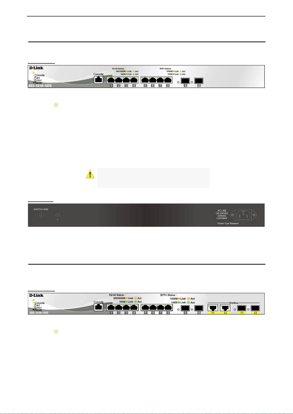
DXS-1210-10TS
8-Port 10GBASE-T and 2-Port SFP + Fiber port L2 10 Gigabit Ethernet Switch.
Front Panel
Figure 1.1 – DXS-1210-10TS Front Panel
Power LED
Console: The console LED lights up when the console port is connected.
Fan error: The Fan error LED lights up when the fan has runtime failure and is brought offline.
Reset: By pressing the Reset button, the Switch will change back to the default configuration and all
changes will be lost.
Port Link/Act/Speed LED (1-8, 9F, 10F): The port LEDs in dicate a net work link throug h the correspon ding
port. Blinking indicates the Switch is either sending or receiving data to the port. W hen the port LED glo ws
amber, it indicates the port is running at 100 mbps or 1000 Mbps. W hen the port LED glows green, it is
running at 10 Gbps.
: The Power LED lights up when the Switch is connected to a power source.
CAUTION: The MiniGBIC ports should use UL
listed Optical Transceiver product, Rated Laser
Class I. 3.3Vdc
Rear Panel
Figure 1.2 – DXS-1210-10TS Rear Panel
Power: Connect the AC power cord to this port.
DXS-1210-12TC
8-port 10GBASE-T and 2-port 10G SFP+ with addit ional 2-port 10G BASE-T /SFP + com bo por t L2 10 Gigabit
Ethernet Switch.
Front Panel
Figure 1.3 – DXS-1210-12TC Front Panel
Power LED
Console: The console LED lights up when the console port is connected.
Fan error: The Fan error LED lights up when the fan has runtime failure and is brought offline.
Port Link/Act/Speed LED (1-8, 9F, 10F, 11F, 12F): The Link/Act/Speed LED flashes, which indicates a
network link through the c orresponding por t. Blinking indicat es that the Switch is eith er sending or rece iving
data to the port. When a port has an amber light, this indicates that the port is running at 100 Mbps or 1000
Mbps. When it has a green light it is running on 10 Gbps.
: The Power LED lights up when the Switch is connected to a power source.
3
Page 10
D-Link DXS-1210 Series User Manual
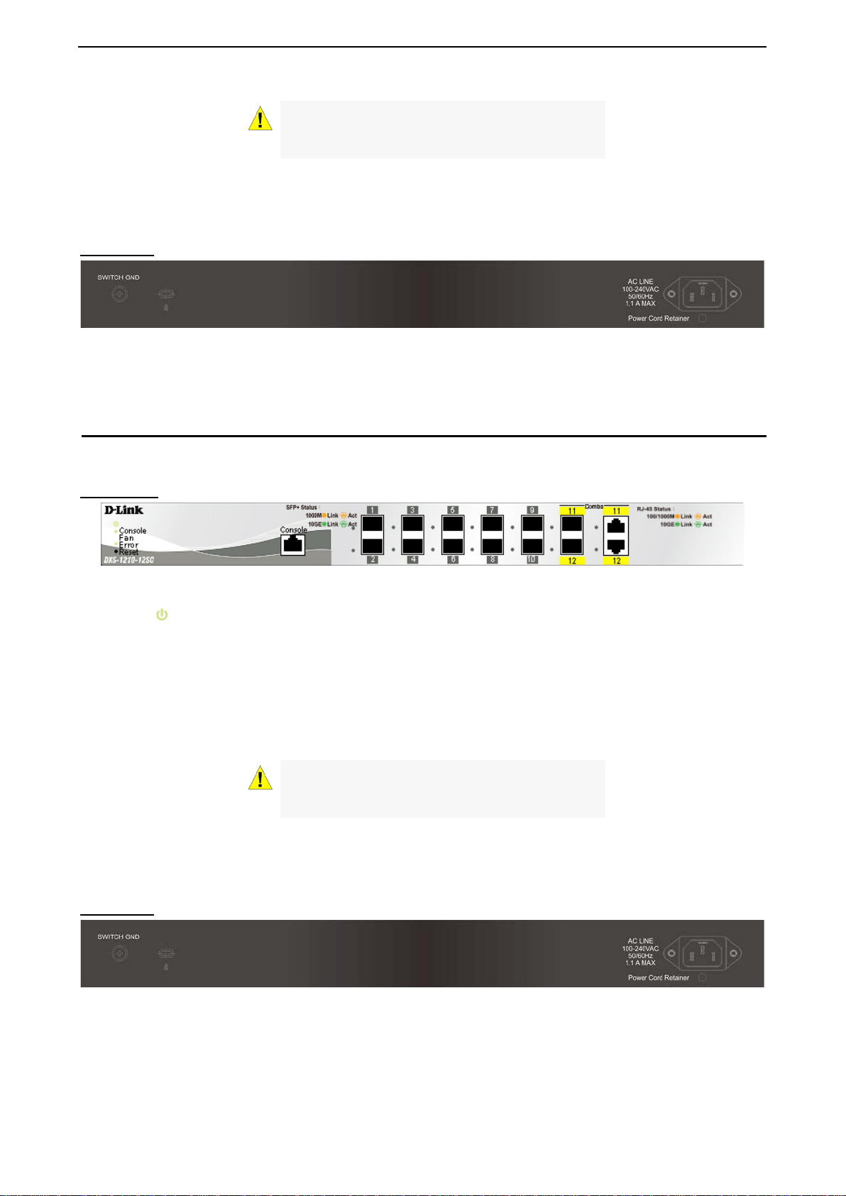
CAUTION: The MiniGBIC ports should use UL
listed Optical Transceiver product, Rated Laser
Class I. 3.3Vdc.
Reset: By pressing the Reset button, the Switch will change back to the default configuration and all
changes will be lost.
Rear Panel
Figure 1.4 – DXS-1210-12TC Rear Panel
Power: Connect the AC power cord to this port.
DXS-1210-12SC
10-Port 10G SFP+ fiber port and 2-port 10GBASE-T/SFP + combo port L2 10 Gigabit Ethernet Switch.
Front Panel
Figure 1.5 – DXS-1210-12SC Front Panel
Power LED
: The Power LED lights up when the Switch is connected to a power source.
Console: The console LED lights up when the console port is connected.
Fan error: The Fan error LED lights up when the fan has runtime failure and is brought offline.
Port Link/Act/Speed LED (1-10, 11F, 12F): The Link/Act/Speed LED flashes, which indicates a network link
through the corresp onding port. Blinking indicates that the S witch is either sendi ng or receiving data t o the
port. When a port has an amber light, th is indicates that the port is running on 100 Mbps or 1000 Mbps.
When it has a green light it is running on 10 Gbps.
CAUTION: The MiniGBIC ports should use UL
listed Optical Transceiver product, Rated Laser
Class I. 3.3Vdc.
Reset: By pressing the Reset button, the Switch will change back to the default configuration and all
changes will be lost.
Rear Panel
Figure 1.6 – DXS-1210-12SC Rear Panel
Power: Connect the AC power cord to this port.
4
Page 11
D-Link DXS-1210 Series User Manual
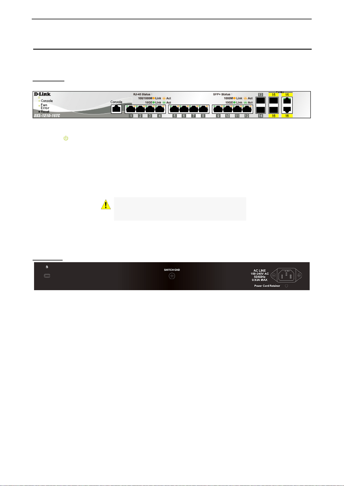
DXS-1210-16TC
12-Port 10G SFP+ fiber port, 2-port 10GBASE-T/SFP+ and 2-port 10BGASE-T/SFP+ combo port L2 10
Gigabit Ethernet Switch.
Front Panel
Figure 1.7 – DXS-1210-16TC Front P an el
Power LED
Console: The console LED lights up when the console port is connected.
Fan error: The Fan error LED lights up when the fan has runtime failure and is brought offline.
Port Link/Act/Speed LED (1-12, 13F, 14F, 15T, 15F, 16T , 16F): The Li nk/Act/Speed LED flashes, which
indicates a network link through the corresponding port. Blinking indicates that the Switch is either sending or
receiving data to the port. When a port has an amber light, this indicates that the port is running on 100 Mbps
or 1000 Mbps. When it has a green light it is running on 10 Gbps.
: The Power LED lights up when the Switch is connected to a power source.
CAUTION: The MiniGBIC ports should use UL
listed Optical Transceiver product, Rated Laser
Class I. 3.3Vdc.
Reset: By pressing the R e set butto n for 1 ~ 5 seconds to reboot the de vice. B y pres s ing the R es et butt on f or
6 ~ 10 seconds, the Switch will change back to the default configuration and all changes will be lost.
Rear Panel
Figure 1.8 – DXS-1210-16TC Rear Panel
Power: Connect the AC power cord to this port.
5
Page 12

D-Link DXS-1210 Series User Manual
2 Hardware Installation
This chapter provides unpacking and installation information for the D-Link DXS-1210 Series Switch.
Safety Cautions
To reduce the ris k of bodily injury, electrical sh ock , fire and damage to the equip ment, obs erve th e followin g
precautions:
• Observe and follow service markings.
• Do not service any product except as explained in your system documentation.
• Opening or removing covers that are marked with the triangular s ymbol with a lightning bolt may
expose you to electrical shock.
• Only a trained service technician should service components inside these compartments.
• If any of the followin g conditions occur, u nplug the product f rom the elect rical o utlet and rep lace the p art
or contact your trained service provider:
• The power cable, extension cable, or plug is damaged.
• An object has fallen into the product.
• The product has been exposed to water.
• The product has been dropped or damaged.
• The product does not operate correctly when you follow the operating instructions.
• Keep your system away from radiators and heat sources. Also, do not block cooling vents.
• Do not spill food or liquids on your system components, and never operate the product in a wet
environment. If the system gets wet, contact your trained service provider.
• Do not push any objec ts into the openings of your s ystem. Doing so can caus e fire or electric shock by
shorting out interior components.
• Use the product only with approved equipment.
• Allow the product to cool before removing covers or touching internal components.
• Operate the product on ly from the type of exter nal po wer sourc e indicated o n the elec trical ratin gs label.
If you are not sure of the type of power source required, consult your service provider or local reseller.
• Also, be sure that attached devices are electrically rated to operate with the power available in your
location.
• Use only approved po wer cabl e(s). If you have not b een pro vided with a power cable f or your s ystem or
for any AC powered optio n intende d for your s ystem, pur chase a po wer c able tha t is appr oved f or use i n
your country. The po wer cabl e must be rat ed for the product and for the vol tage and cur rent m arked on
the product’s electr ical ratings label. T he voltage and current r ating of the cable s hould be greater than
the ratings marked on the product.
• To help prevent electric shock, plug the system and peripheral power cables into properly grounded
electrical outlets.
• These cables are equippe d with three-prong plugs to help ensure proper grounding. Do not
use adapter plugs or rem ove the grounding prong f rom a cable. If you m ust use an extension
cable, use a 3-wire cab le with properly grounded plugs.
• Observe extension cabl e and power str ip ratings. Mak e sure that the total ampere rating of all
products plugged into th e extension cable or power strip does not exc eed 80 percent of the
ampere ratings limit for the extension cable or power strip.
• To help protect your system from sudden, transient increases and decreases in electrical
power, use a surge suppressor, line conditioner, or uninterruptible power supply (UPS).
• Position system cables and power cables carefully; route cables so that they cannot be
stepped on or tripped over. Be sure that nothing rests on any cables.
• Do not modify power cables or plugs. Consult a licensed electrician or your power company for
site modifications.
• Always follow your local/national wiring rules.
• When connecting or disc onnecting power t o hot-p luggabl e power suppl ies, if offer ed with your
system, observe the following guidelines:
6
Page 13
D-Link DXS-1210 Series User Manual
• Install the power supply before connecting the power cable to the power supply.
• Unplug the power cable before removing the power supply.
• If the system has multiple sources of power, disconnect power from the system by
unplugging all power cables from the power supplies.
• Move products wit h care; ensure that a ll casters and/or stab ilizers are firml y connected to the s ystem.
Avoid sudden stops and uneven surfaces.
Step 1: Unpacking
Open the shipping carton and carefully unpack its contents. Please c onsult the packing list located in the
User Manual to make sure all items are present and undamaged.
One D-Link DXS-1210 Series switch
One Multilingual Getting Started Guide
User Guide CD
One RJ-45 console cable
Power Cord and Power Cord Retainer
Rack-mount kit and Rubber Feet
If any item is found missing or damaged, please contact the local reseller for replacement.
Step 2: Switch Installation
For safe switch installation and operation, it is recommended that you:
Visually inspect the power cord to see that it is secured fully to the AC power connector.
Make sure that there is proper heat dissipation and adequate ventilation around the switch.
Do not place heavy objects on the switch.
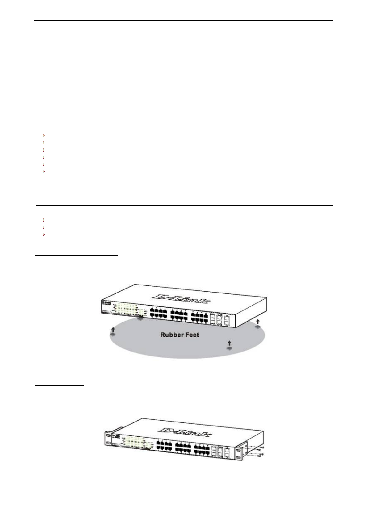
Desktop or Shelf Installation
When installing the switc h on a desktop or shelf, the r ubber feet included w ith the device must be attac hed
on the bottom at each cor ner of the device’s base. All ow enough ventilation s pace between the dev ice and
the objects around it.
Figure 2.1 – Attach the adhesive rubber pads to the bottom
Rack Installation
The switch can be mounted in an EIA standard size 19-inch r ack, which can be plac ed i n a wirin g closet with
other equipment. T o install, attac h the m ounting br ackets to th e swit ch’s side p anels (one on each s ide) and
secure them with the screws provided (with 8 M3*6.0 size screws).
Figure 2.2 – Attach the mounting brackets to the Switch
7
Page 14
D-Link DXS-1210 Series User Manual
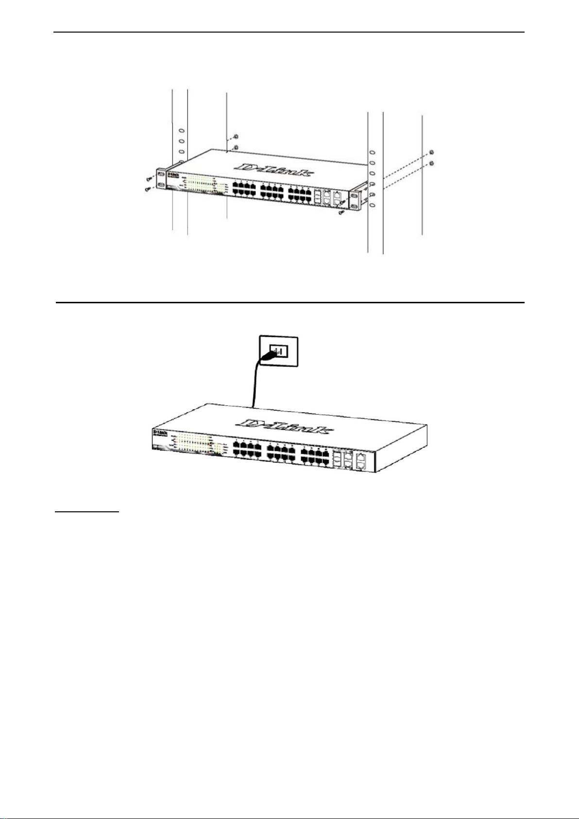
Then, use the screws provided with the equipment rack to mount the switch in the rack.
Figure 2.3 – Mount the Switch in the rack or chassis
Step 3 – Plugging in the AC Power Cord
The Switch can now be connected to the AC power. Connect the AC power cord to the rear of the switch and
to an electrical outlet (preferably one that is grounded and surge protected).
Figure 2.4 –Plugging the switch into an outlet
Power Failure
As a precaution, th e switch s hould be u nplugged in cas e of power f ailure. W hen po wer is resum ed, plug t he
switch back in.
8
Page 15
D-Link DXS-1210 Series User Manual
3 Getting Started
This chapter introduces the management interface of D-Link DXS-1210 Series Switch.
Management Options
The D-Link DXS-1210 Series Switch can be managed through any port by using the Web-based
Management, or through any PC using CLI commands.
Each switch must be assigned its own IP Address , which is used for comm unication with the Web-Based
Management or a SNMP network m anager. The PC shou ld have an IP address in the sam e subnet as the
switch. Each switch can allow up to four users to access the Web-Based Management concurrently.
Please refer to the following installation instructions for the Web-based Management.
Using Web-based Management
After a successf ul ph ysica l ins ta lla tio n, you can configure the Switch, monitor the network status , an d d is play
statistics using a web browser.
Supported Web Browsers
The embedded Web-based Management currently supports the following web browsers:
Internet Explorer 8 or later version
Chrome
Firefox
Safari
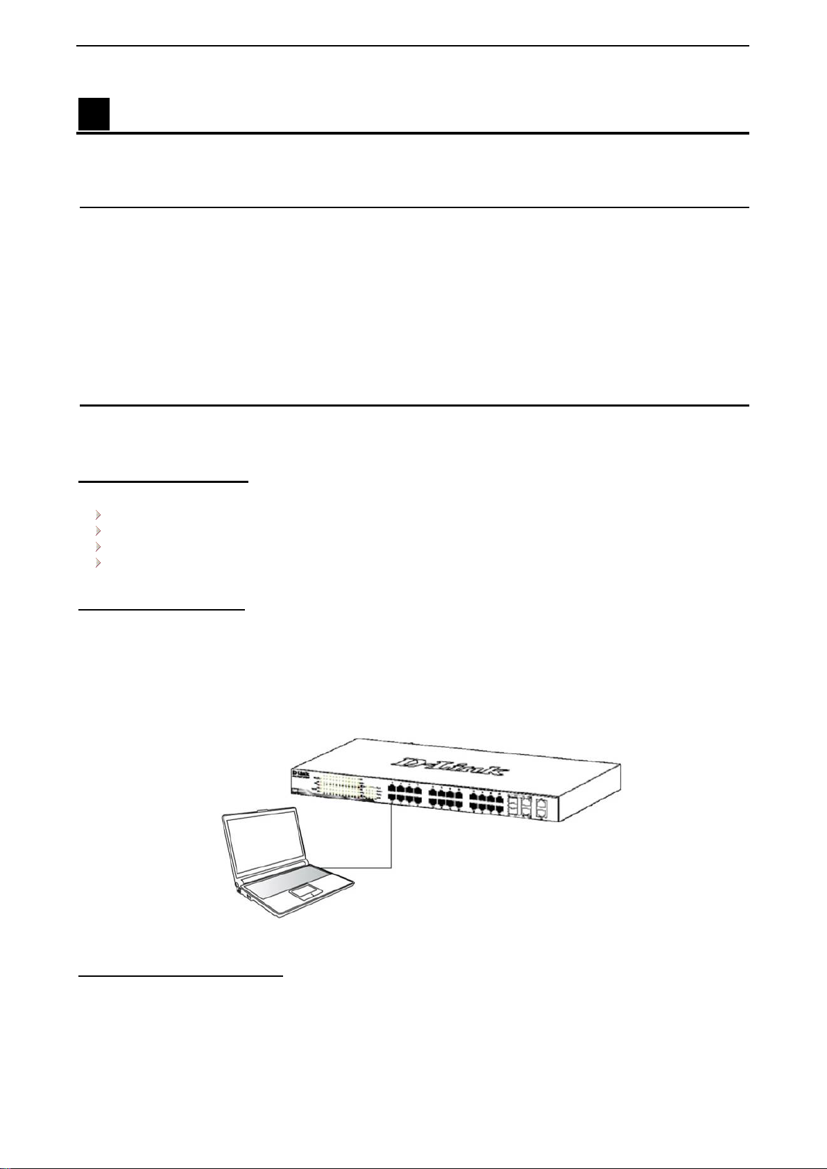
Connecting to the Switch
You will need the following equipment to begin the web configuration of your device:
1. A PC with a RJ-45 Ethernet connection
2. A standard Ethernet cable
Connect the Ethernet cable to any of the ports on the front panel of the switch and to the Ethernet port on the
PC.
Figure 3.1 – Connected Ethernet cable
Login Web-based Management
In order to login and conf igure the s witch via Web-based GUI, th e PC must have an IP address in the same
subnet as the s witch. F or example, if the s witc h h as a n I P addr es s of 10.90.90.90, the PC should have an IP
address of 10.x.y.z (where x/y is a number between 0 ~ 254 and z is a number between 1 ~ 2 54), and a
subnet mask of 255.0.0.0. There are two ways to launch the Web-based Management.
9
Page 16
D-Link DXS-1210 Series User Manual
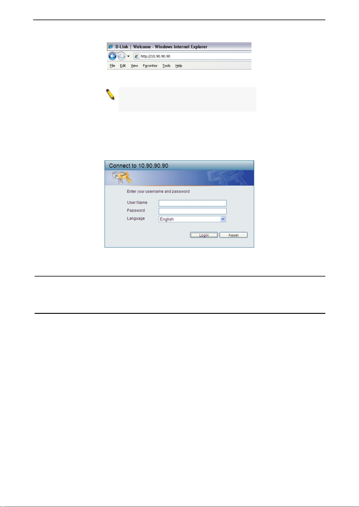
Figure 3.2 –Enter the IP address 10.90 .90.90 in the web browser
NOTE: T he switch's f actor y default IP addres s is
10.90.90.90 with a subne t m ask of 255.0.0 .0 and
a default gateway of 0.0.0.0.
When the following login dialog box appears, enter the password and choose the language of the Webbased Management interface then click OK.
The switch supports 10 languages including English, Traditional Chinese, Simplified Chinese, German,
Spanish, French, Ita lian, Portuguese, Japan ese and Russian. B y default, the Usernam e and Password are
empty and the language is English.
Figure 3.3 – Login Dialog Box
Smart Wizard
After a successful login, the Smar t Wizard will guide you t hrough essential s ettings of the D-Link DXS-1210
Series Switch. Please refer to the Smart Wizard Configuration section for details.
Web-based Management
By clicking the Exit button in the Smart Wizard, you w il l e nter the Web-based M an agement interface. Please
refer to Chapter 4 Configuration for detailed instructions.
10
Page 17
D-Link DXS-1210 Series User Manual
The IPv4 Information of Smart Wizard
4 Configuration
The features and functions of the D-Link DXS-1210 Series Switch can be configured for optimum use
through the Web-based Management Utility.
Smart Wizard Configuration
After a successful login, the Smar t Wizard will guide you t hrough essential s ettings of the D-Link DXS-1210
Series Switch. If you do not plan to change anything, click Exit to leave the Wizard and enter the Web
Interface. You c an also skip it by clicking Ignore the wizard next time f or the next time you logon to the
Web-based Management.
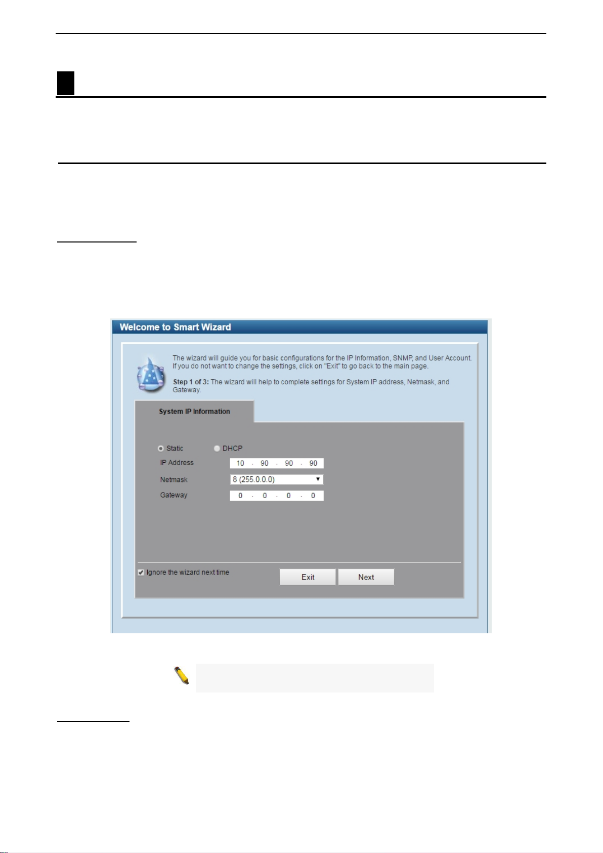
IPv4 Information
IPv4 Information will guide you to do basic configurations on 3 steps for the IP Information, access password,
and SNMP. Select Static, to manually e nter a new IP Address, Netmask and Gateway address, or select
DHCP to automaticall y receive IP settings from a DHCP serv er. Click the Next button to enter the SNMP
settings page The IP address is allowed for IPv4 and IPv6 address. If you are not changing the settings, click
Exit button to go back to the main page. Or you can click on Ignore the wizard next time to skip wizard
setting when the switch boots up.
Figure 4.1 – IPv4 Information in Smart Wizard
NOTE:
does not support IPv6 address.
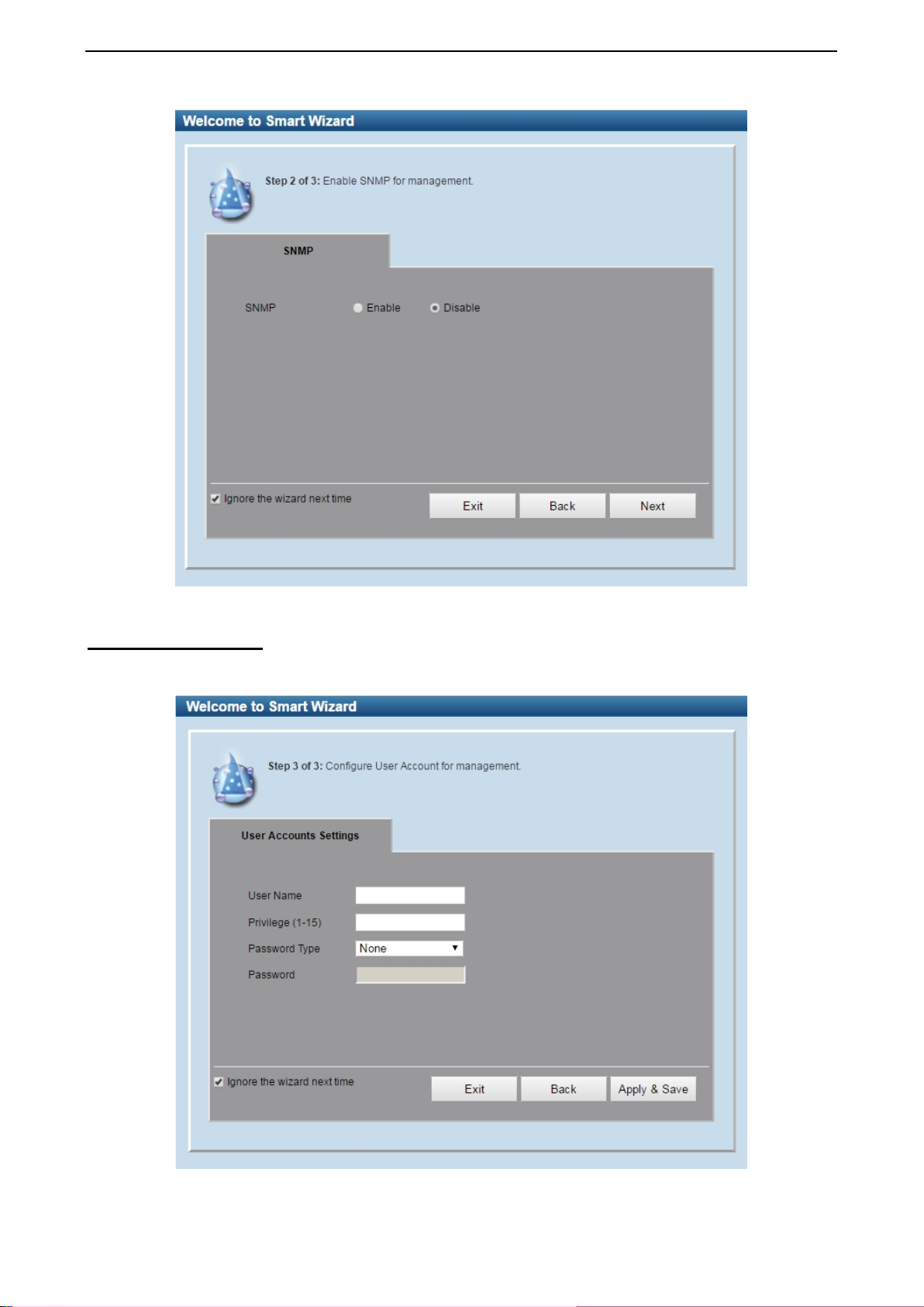
SNMP Settings
The SNMP Settings page allows you to quic kly enable/disable the SNMP function. The default SNMP Setting
is Disabled. Click Enabled and then click Next, then it will enter the User Accounts Settings page.
11
Page 18
D-Link DXS-1210 Series User Manual
Figure 4.2 – SNMP Settings in Smart Wizard
User Accounts Settings The User Ac counts Settings page allows you to quic kly specify the us er account function. Enter the User
Name, Privilege, Password Type and Password. Click Apply & Save to save the configuration.
Figure 4.3 – User Accounts Setting in Smart Wizard
12
Page 19
D-Link DXS-1210 Series User Manual
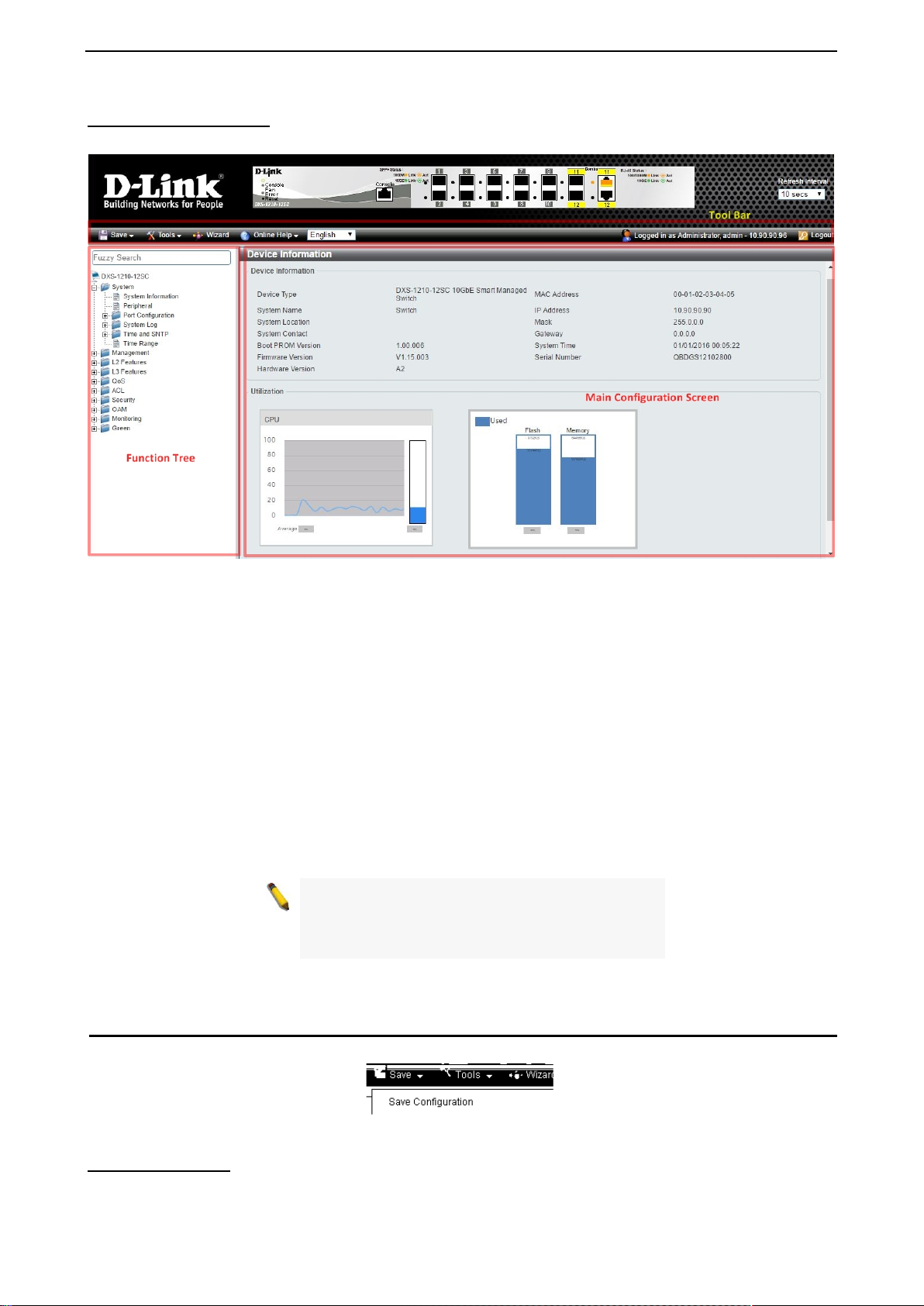
Web-based Management After clicking the Exit button in the Smart Wizard you will see the screen below:
Figure 4.4 – Web-based Management
The above image is the Web-based Management screen. The three main areas a r e the Tool Bar on top, the
Function Tree, and the Main Configuration Screen.
The Tool Bar provides a quick and convenient way for essential utility functions like firmware and
configuration management.
By choosing different functions in the Function Tree, you can change all the settings in the Main
Configuration Screen. The main configuration s cr ee n wil l show the current stat us of your Switch by click ing
the model name on top of the function tree.
At the upper right corner of the screen the username and current IP address will be displayed.
Under the username is the Logout button. Click this to end this session.
NOTE: If you close the web browser without
clicking th e Logout button first, then it wil l b e seen
as an abnormal ex it and the log in session will s till
be occupied.
Click the D-Link logo at the upper-left corner of the screen to be redirected to the local D-Link website.
Tool Bar > Save Menu
The Save Menu provides Save Configuration and Save Log functions.
Figure 4.5 – Save Menu
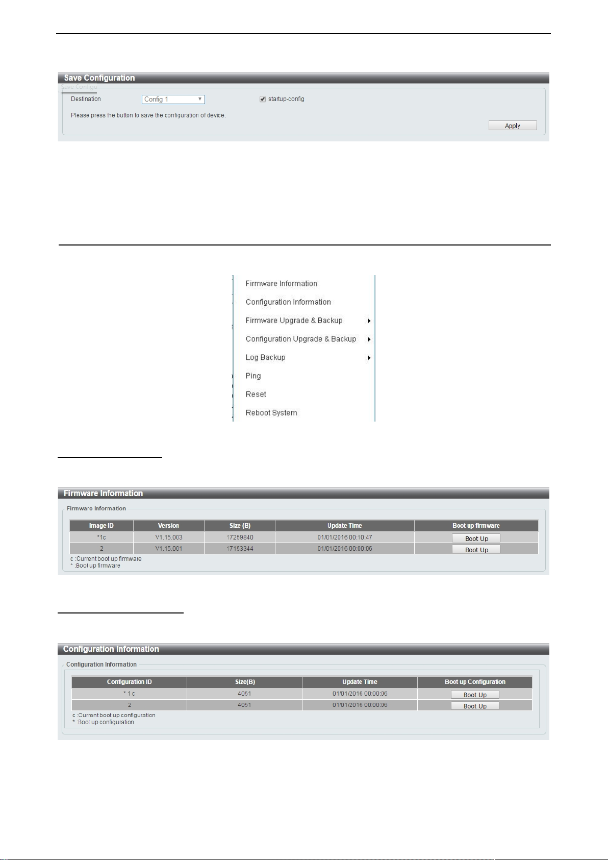
Save Configuration
Select Save configuration to save the configuration changes to the Switch’s non-volatile RAM.
13
Page 20
D-Link DXS-1210 Series User Manual
Figure 4.6 – Save Configuration
Destination: Select the destination to save the configuration to.
Startup-config: Check the box to enable the startup configuration function.
Click the Apply button to save your settings.
Tool Bar > Tool Menu
The Tool Menu off ers global functions contro ls such as Reset, Reboot Device, Conf iguration Backup and
Restore, Firmware Backup and Upgrade.
Figure 4.7 – Tool Menu
Firmware Information
Display the firmware for the 2 f irm ware images, including the im age that has been booted and the image that
is selected for the next reboot.
Figure 4.8 – Tool Menu > Firmware Information
Configuration Information
Display information for the Switch configuration. This includes the configuration that has been loaded and the
configuration that is selected for the next reboot.
Figure 4.9 – Tool Menu > Configuration Information
14
Page 21
D-Link DXS-1210 Series User Manual
and all current
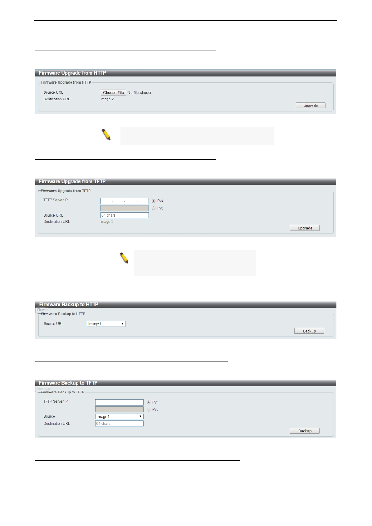
Firmware Upgrade & Backup > Firmware Upgrade from HTTP
To upgrade the firmware of Switch fr om a firmware file, select a Source URL, firm ware Destination URL
and click Upgrade. The specified firmware file will be uploaded to the Switch via HTTP.
Firmware Upgrade & Backup > Firmware Upgrade from TFTP
Upgrade firmware us ing TFTP. Enter the T FT P IP a ddress, source URL, and select a Destinat ion URL. Click
Upgrade.
Figure 4.10 – Tool Menu > Firmware Upgrade & Ba ckup > Firmware Upgrade from HTTP
Note: The Switch will reboot after restoring the
firmware, and all current configuration will be los t.
Figure 4.11 – Tool Menu > Firmware Upgrade & Backup > Firmware Upgrade from TFTP
Note: The Switch will reboot after
restoring the firmware,
configuration will be lost.
Firmware Backup to HTTP & Backup > Firmware Backup to HTTP To save a backup of the firmware, select the source URL and then click Backup.
Figure 4.12 – Tool Menu > Firmware Upgrade & Backup > Firmware Backup to HTTP
Firmware Backup to HTTP & Backup > Firmware Backup to TFTP
To save a backup of the firmware us ing TFTP, enter t he TFTP ser ver IP address, the source URL, and the
destination URL. Click Backup.
Figure 4.13 – Tool Menu > Firmware Upgr ad e & Ba ckup > Firmware Backup to TFTP
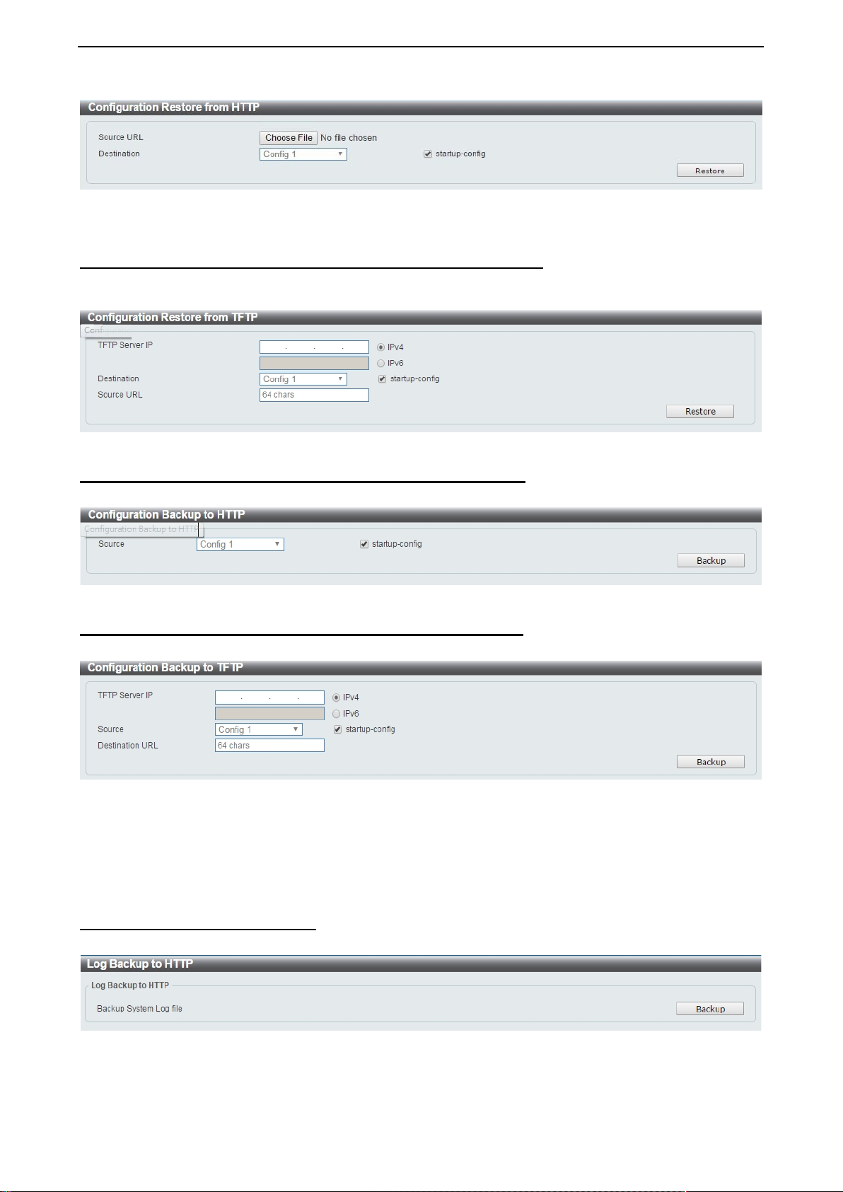
Configuration Upgrade & Backup > Configurati o n Restore from HTTP
To restore the S witch from a save d configuration f ile, select a Source URL , configuration Destination and
click Restore.
15
Page 22
D-Link DXS-1210 Series User Manual
Figure 4.14 – Tool Menu > Configurat ion Upgrade & Backu p > Configuration Restore from HTTP
Startup-config: Check the box to enable the startup configuration function.
Configuration Upgrade & Backup > Configurati o n Restore from TFTP
To load the Switch’s configuration from a saved configuration file using TFTP, enter the TFTP server IP
address, destination image and source URL, then click Restore.
Figure 4.15 – Tool Menu > Configuration Upgrade & Backup > Configuration Restore from TFTP
Configuration Upgrade & Backup > Configuratio n Backup to HTTP To save the current configuration to a file, click Backup.
Figure 4.16 – Tool Menu > Configuration Upgrade & Backup > Configuration Backup to HTTP
Configuration Upgrade & Backup > Configurati o n Backup to TFTP To save the current configuration to a file using TFTP, click Backup.
Figure 4.17 – Tool Menu > Configuration Upgrade & Backup > Configuration Backup to TFTP
TFTP Server IP: Select IPv4 or IPv6 and enter the IP address.
Source: Select the source configuration file.
Startup-config: when checking the box, only the cur rent startup conf iguration file wi ll be backed up, which
may be stored in the “Config 1” or “Config 2” location.
Destination URL: Enter the destination URL for the backup.
Log Backup > Log Backup to HTTP To save the log to a file and click Backup.
Figure 4.18 – Tool Menu > Log Backup > Log Backup to HTTP
16
Page 23
D-Link DXS-1210 Series User Manual
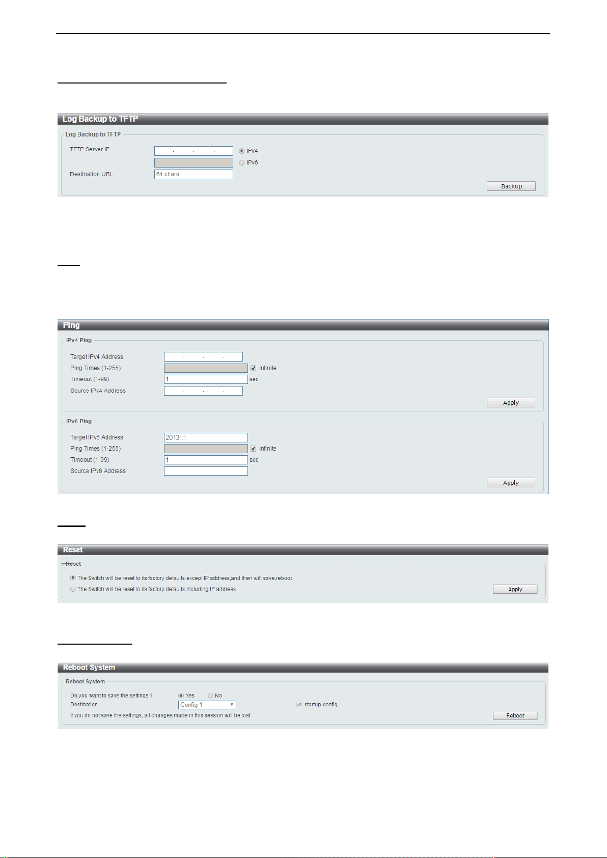
Log Backup > Log Backup to TFTP
To save the log to a file using TFTP, enter the TFTP server IP address and destination URL then click
Backup.
Figure 4.19 – Tool Menu > Log Backup > Log Backup to TFTP
TFTP Server IP: Select IPv4 or IPv6 and enter the IP address.
Destination URL: Enter the destination URL for the backup.
Ping To ping a computer or device, enter either Target IPv4 Address or Target IPv6 Address, Ping Times,
Timeout and Source IPv4 Address or Source IPv6 Address. Enter the required information, tick the
Infinite option to disable the Ping Times feature, and click Apply. The results will be displayed in the Result
box.
Figure 4.20 – Ping
Reset Select which reset option you want to perform and click Apply.
Figure 4.21 – Tool Menu > Reset
Reboot System Select to save your current settings and then click Reboot to restart the Switch.
Figure 4.22 – Tool Menu > Reboot System
Destination: Select the configuration destination to be saved.
Startup-config: When checking the box, only the current startup config uration file will be backed up which
may be stored in the “Config 1” or “Config 2” location.
17
Page 24
D-Link DXS-1210 Series User Manual
Tool Bar > Smart Wizard
By clicking the Smart Wizard button, you can re-run to the Sm ar t W izard if you wish to make any changes.
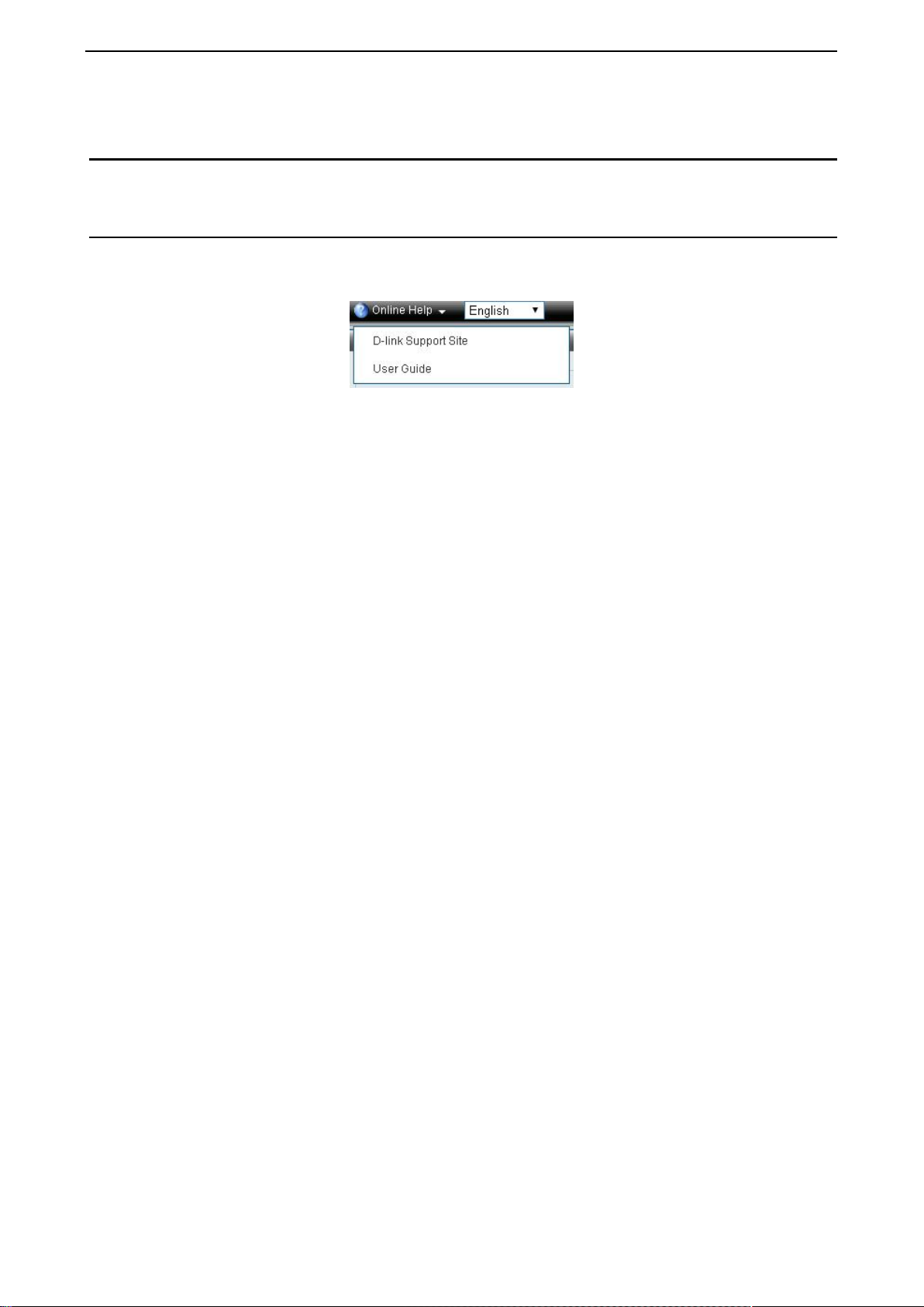
Tool Bar > Online Help
The Online Help provides two ways of online support: D-link Support Site will lead you to the D-Link
website where you c an fi nd on line res ources such as updated firm ware; User Guide c an of fer an imm ediate
reference for the feature definition or configuration guide.
Figure 4.23 – Online Help
18
Page 25
D-Link DXS-1210 Series User Manual
Figure 4.24 – User Guide Micro Site
19
Page 26
D-Link DXS-1210 Series User Manual
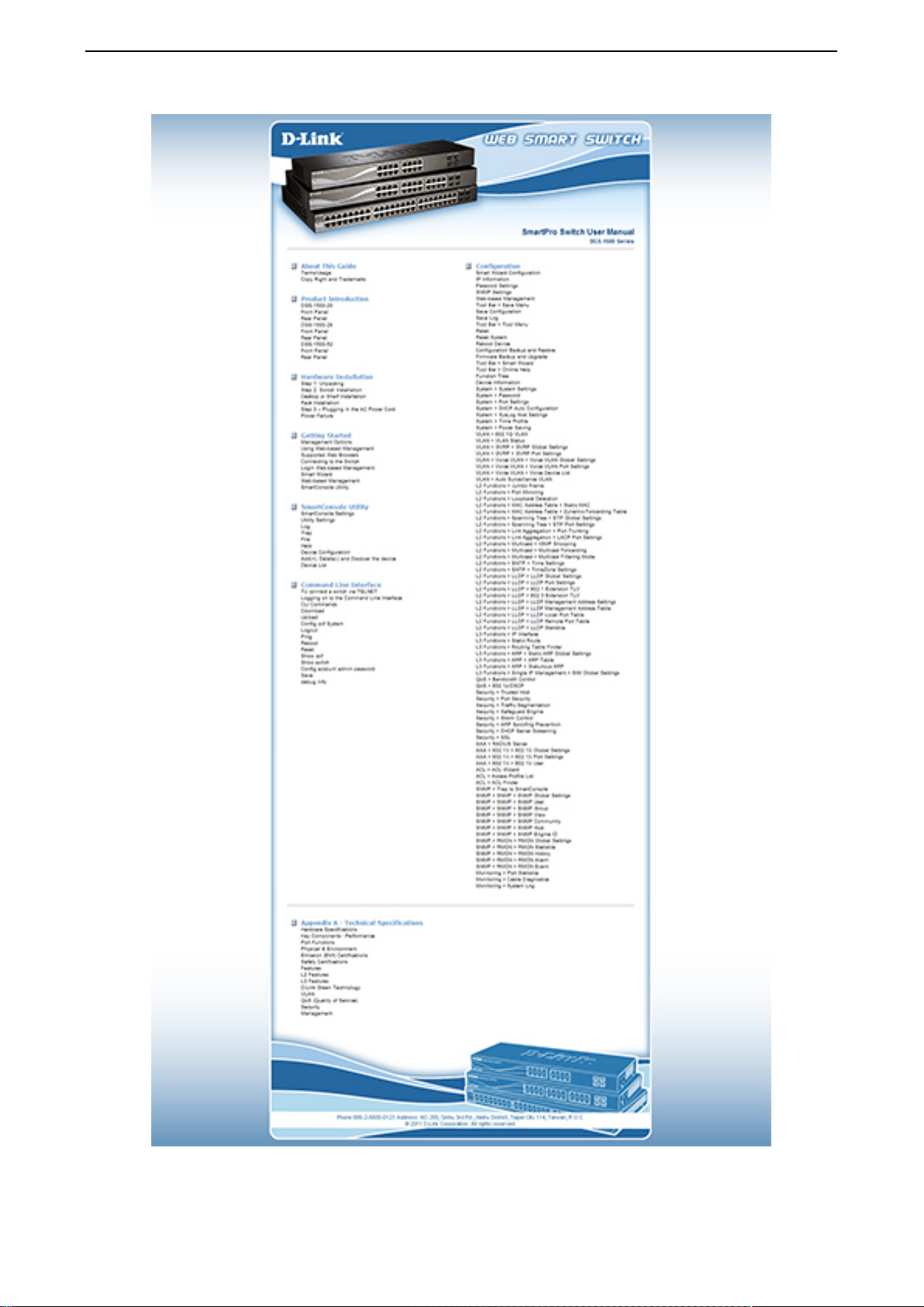
Function Tree
All configuration op tions on the switch are acces sed through the Setup menu on the left s ide of the main
window. Click on the setup item that you want to conf igure. The following sections pro vide more detailed
description of each feature and function.
Figure 4.25 –Function Tree
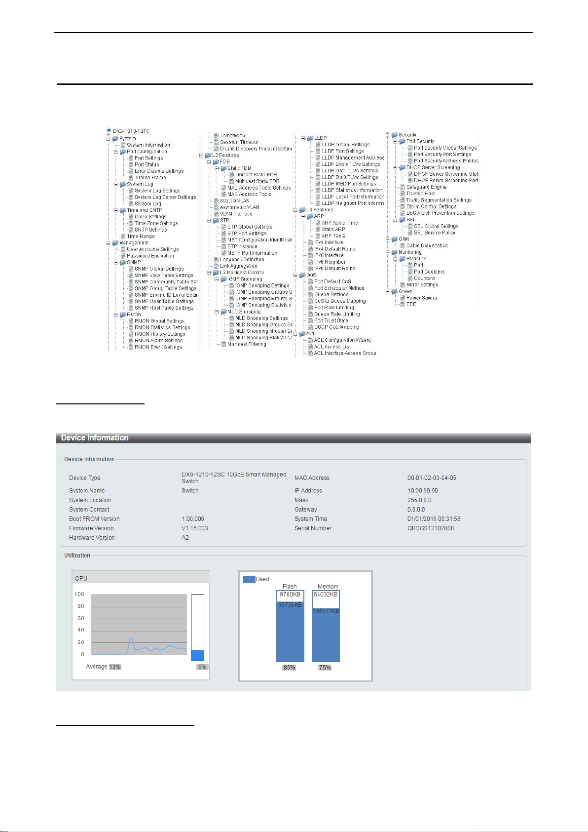
Device Information
The Device Inform ation pro vides an overvie w of the s witch, including essentia l inf ormation suc h as f irmware
& hardware information, and IP settings.
Figure 4.26 – Device Information
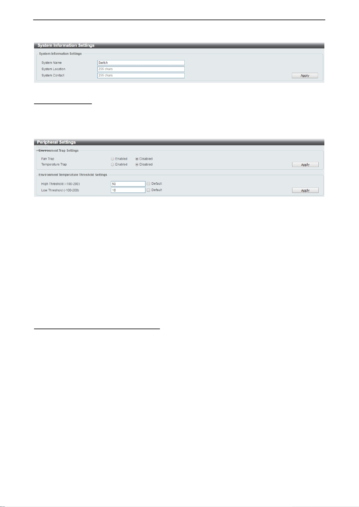
System > System Information
The System Setting page allows you to configure basic system information.
System Information Settings: Enter a System Name, System Location and System Contact.
20
Page 27
D-Link DXS-1210 Series User Manual
Figure 4.27 – System > System Information
System > Peripheral
The Peripheral pa ge allows user to configure the environment trap settings an d environment temperature
threshold settings.
System Information Settings: Enter a System Name, System Location and System Contact.
Figure 4.28 – System > Peripheral
Environment Trap Settings:
Fan Trap: Select to enable or disable the fan trap state for waning fan event (fan failed or fan recover).
Temperature Trap: Select to enable or disable the temperature trap state for waning temperature event
(temperature exceeds the thresholds or temperature recover).
Environment Temperature Threshold Settings:
High Threshold (-100-200): Enter the high threshold value of the warning tem peratur e sett ing. T he ran ge is
from -100 to 200 Celsius degree. Tick the Default check box to return to the default value.
Low Threshold (-100-200): Enter the low t hreshold valu e of the warn ing temperatur e setting. T he range is
from -100 to 200 Celsius degree. Tick the Default check box to return to the default value.
Click the Apply button to accept the changes made.
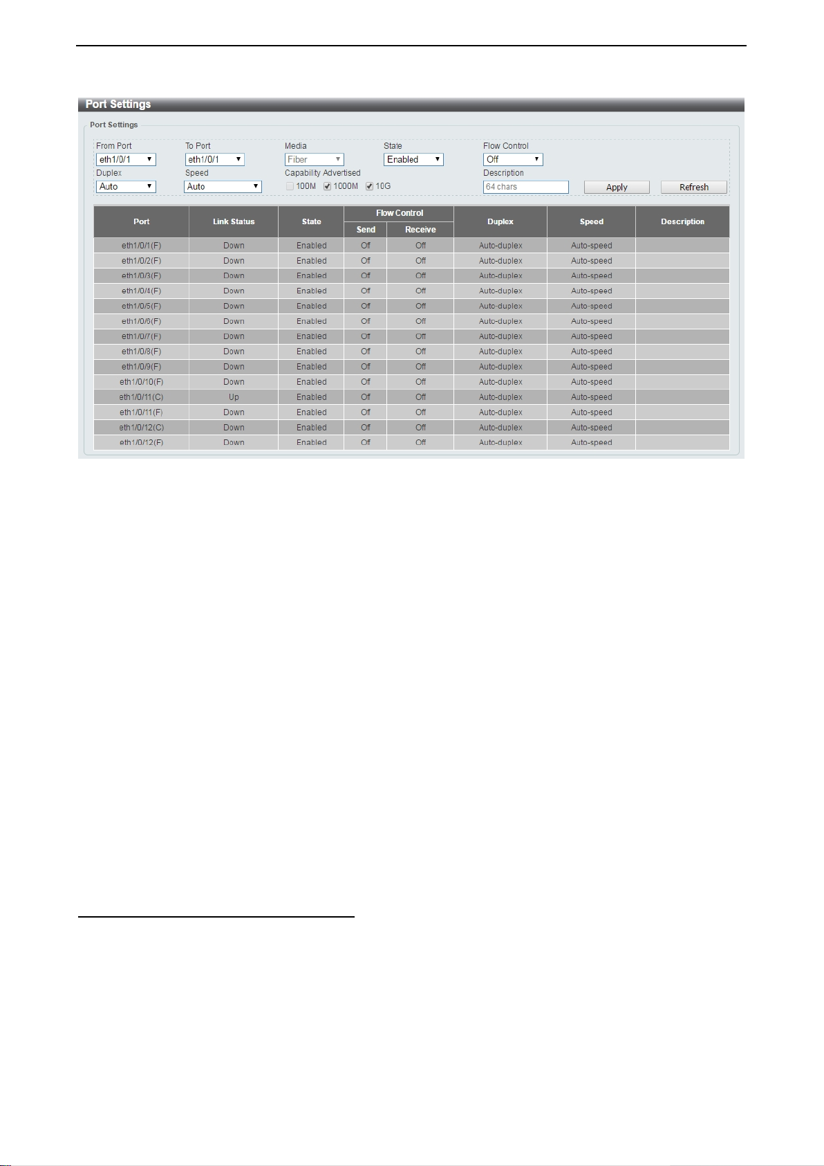
System > Port Configuration > Port Settings In the Port Settings page, the status of all ports can be monitored and adjusted for optimum configuration.
21
Page 28
D-Link DXS-1210 Series User Manual
Figure 4.29 – System > Port Configuration > Port Settings
From Port / To Port: Select the appropriate port range to be configured.
State: Enable or disable the physical port.
Auto Downgrade: To enable or disable automatically downgrading the advertised speed, in-case a link
cannot be established at the available speed.
Flow Control: Select On or Off. Ports configured f or full-duplex use 802.3x flow control, half-duplex ports
use back-pressure flow control, and Auto ports use an automatic selection of the two.
Duplex: Select the duplex mode used. Options to choose from are Auto and Full.
Speed: Select the speed f or the ports. The speed va lues are Auto, 100M, 1000M, 1000M Master, 1000M
Slave, and 10G. The Switch allows you to c onfigure two types of Gigabit connections ; 1000M Mast er and
1000M Slave which refer to connections runnin g a 1000BASE-T cable for c onnection between the Switch
port and another device c apable of a Gigabit connec tion. The mas ter setting (1000M Master) will allow the
port to advertise c apabilities related to duplex, speed and physical la yer type. The master settin g will also
determine the mas ter and slave rel ationship bet ween the two con nected ph ysical la yers. This relatio nship is
necessary for establis hing the timing c ontrol between the t wo physical la yers. The timing contr ol is set on a
master physical la yer by a local sour ce. The s lave setti ng (1000M Slave) uses loop timing, where the tim ing
comes from a data stream r eceived from the master. If one connectio n is set for 1000M Mast er, the other
side of the connection must be s et for 1000M Slav e. Any other configuration will res ult in a link down status
for both ports.
Capability Advertised: When the Speed is set to Auto, these capabilities are advertised during autonegotiation.
Description: Enter a 64 characters description for the corresponding port.
Click Apply button to save your settings.
Click the Refresh button to refresh the display table.
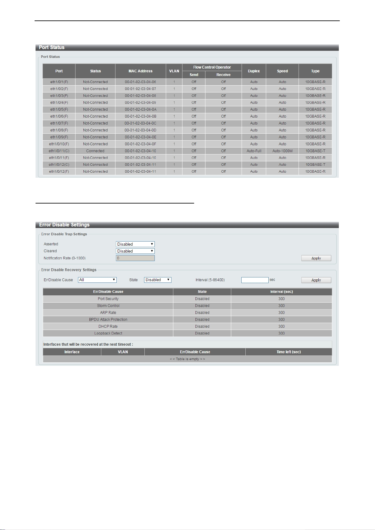
System > Port Configuration > Port Status
The Port Settings page allows you to view the Switch’s physical port status and settings. The table will
display the Port, Status, MAC Address, VLAN, Flow Control Operator, Duplex, Speed and Type.
22
Page 29
D-Link DXS-1210 Series User Manual
Figure 4.30 – System > Port Configuration > Port Status
System > Port Configuration > Error Disable Settings
The Error Disable Settings page allows you to configur e the sending of SNM P notifications f or error disable
state.
Figure 4.31 – System > Port Configuration > Error Disable Settings
Error Disable Trap Settings:
Asserted: Select to enable or disable the notifications when entering into the error disabled state.
Cleared: Select to enable or disable the notifications when exiting from the error disabled state.
Notification Rate (0-1000): Enter the number of traps per m inute. The pack ets that exceed the rate will be
dropped. The value is between 0 and 1000.
Click the Apply button to save your settings.
Error Disable Recovery Settings:
ErrDisable Cause: Spec ify the error disa ble causes. Options to choose f rom are All, Port Security, Storm
Control, ARP Rate, BPDU Protect Protection, DHCP Rate and Loopback Detect.
State: Select to enable or disable the auto-recovery for an error port caused by the specified cause.
Interval (5-586400): Enter the time interval. The values are between 5 and 586400 seconds.
Click the Apply button to save your settings.
23
Page 30
D-Link DXS-1210 Series User Manual
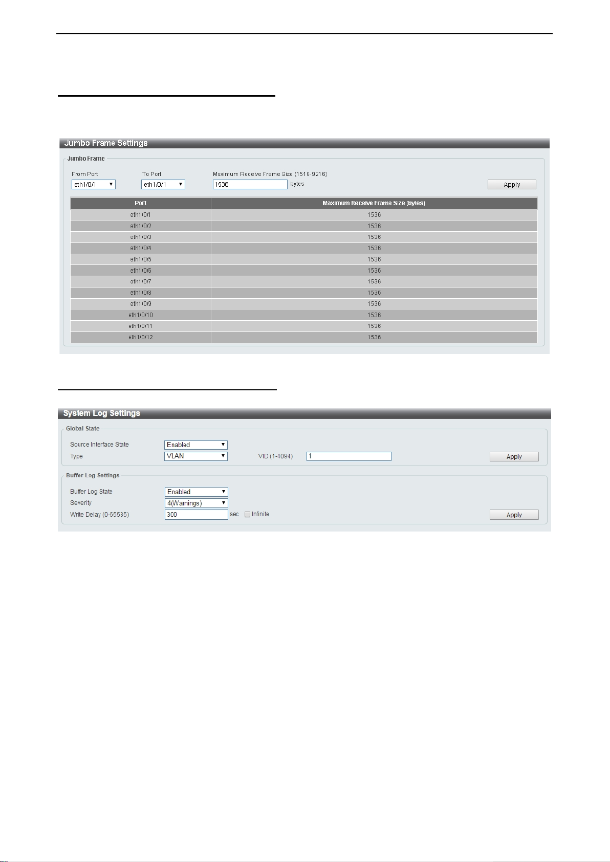
System > Port Configuration > Jumbo Frame
The Jumbo Frame page allows you to vie w and c onf ig ure t he Jumbo Frame size and settings . J umbo frames
are Ethernet frames with more than 1,518 bytes of payload. The Switch supports jumbo frames with a
maximum frame size of up to 9216 bytes.
Figure 4.32 –System > Port Configuration > Jumbo Frame
System > System Log > System Log Settings
The System Log Settings p age al lo ws you to view and configure the system’s log settings.
Figure 4.33 – System > System Log > System Log Settings
Global State:
Source Interface State: Select to enable or disable the source interface’s global state.
Type: Select the type of interface that will be used. The default option is VLAN.
VID (1-4094): Specifies the VLAN ID. The possible range is 1 – 4094.
Click the Apply button to save your settings.
Buffer Log Settings:
Buffer Log State: Select to enable or disable the buffer log state.
Severity: Select the severity value of the type of information that will be logged. The values are 0
(Emergencies), 1 ( Alerts), 2 (Crit ical), 3 (Er rors), 4 (Warnings), 5 (Notifications), 6 (Informational), and 7
(Debugging).
Write Delay (0-65535): Enter the interval for periodic writing of th e logging buffer to flash. T he value is
between 0 and 65535 sec o nds . An d def au lt is 3 00 s econds. Tick the Infinite opt ion, t o d isab le th e writ e de lay
feature.
Click the Apply button to save your settings.
24
Page 31

D-Link DXS-1210 Series User Manual
System > System Log > System Log Server Settings
The System Log Server Settings page allows you to view and configure the system log’s server settings.
Figure 4.34 – System > System Log > System Log Server Settings
IP Address: Select and enter the IPv4 address or IPv6 Address.
UDP Port (514 or 1024-65535): Enter the system lo g s erver’s U DP por t num ber . T his value m ust be 51 4 or
between 1024 and 65535. The default value is 514.
Severity: Select the severity value of the type of inform ation that wi ll be logg ed. Options to choose f rom ar e
0 (Emergencies), 1 (Alerts), 2 (Critical), 3 (Errors), 4 (Warnings), 5 (Notifications), 6 (Informational),
and 7 (Debugging).
Facility: Select the facility value. The values must be between 0 and 23.
Click the Apply button to save your settings and click the Delete button to remove the entry.
System > System Log > System Log
The System Log page displays the system logs on the Switch.
Figure 4.35 – System > System Log > System Log
System > Time and SNTP > Clock Settings
The Clock Settings page allows you to configure the time settings for the Switch.
Figure 4.36 – System > Time and SNTP > Clock Settings
25
Page 32

D-Link DXS-1210 Series User Manual
Time (HH:MM:SS): Enter the current time in hours, minutes, and seconds.
Data (DD/MM/YYYY): Enter the current day, month, and year to update the system clock.
Click the Apply button to save your settings.
System > Time and SNTP > Time Zone Settings
The Time Zone Settings page allows you to configure time zones and Daylight Saving Time settings for
SNTP.
Figure 4.37 – System > Time and SNTP > Time Zone Settings
Summer Time Stat e: Select Summer Time State setting. Options to choos e f r om ar e Disabled, Recurring
Setting, and Date Setting.
Time Zone: Select the local time zone’s offset from Coordinated Universal Time (UTC).
The Recurring Setting can be configured below:
From: Week of the Month – Select week of the month that daylight saving time will start.
From: Day of the Week - Select day of the week that daylight saving time will start.
From: Month – Select the month that daylight time will start.
From: Time in HH MM – Select the time of the day that daylight saving time will start.
To: Week of the Month – Select week of the month that daylight saving time will end.
To: Day of the Week – Specify day of the week that daylight saving time will end.
To: Month – Select the month that daylight saving time will en d .
To: Time In HH MM – Select the time of the day that daylight saving time will end.
Offset – Enter the number of m inutes to add during daylight saving time. T he default value is 60. The r ange
of this offset is 30, 60, 90 and 120.
The Date Setting can be configured below:
From: Date of the Month – Select date of the month that daylight saving time will start.
From: Month – Select the month that daylight saving time will start.
26
Page 33

D-Link DXS-1210 Series User Manual
From: Year – Select the year that the daylight saving time will start.
From: Time In HH MM – Select the time of the day that daylight saving time will start.
To: Date of the Month – Select the date of the month that daylight saving time will end.
To: Month – Select the month that daylight saving time will en d .
To: Year – Select the year that the daylight saving time will end .
To: Time In HH MM – Select the time of the day that daylight time will end.
Offset – Select the num ber of minutes to add during daylight saving
of this offset is 30, 60, 90 and 120.
time. The default value is 60. The range
Click the Apply button to save your settings.
System > Time and SNTP > SNTP Settings
The SNTP Settings page allows you to configure the time settings for the Switch.
Figure 4.38 – System > Time and SNTP > SNTP Settings
SNTP Global Settings:
SNTP State: Select to enable or disable the SNTP state.
Poll Interval (30-99999): Enter the poll interval. The value is from 30 to 99999 seconds . The def au lt inter val
is 720 seconds.
Click the Apply button to save your settings.
SNTP Server Setting:
IPv4 Address: Enter the IPv4 address of the SNTP server which provides the clock synchronization.
IPv6 Address: Enter the IPv6 address of the SNTP server which provides the clock synchronization.
Click the Apply button to add the SNTP server.
System > Time Range
The Time Range page allows you to view and configure the time range settings for the Switch.
Figure 4.39 – System > Time Range
27
Page 34

D-Link DXS-1210 Series User Manual
Range Name: Enter a name for the time range. The name can be up to 32 characters long.
From Week / To W eek: Select the starting and ending days of the week that will be used for this time range.
Tick the Daily option to us e this time range for every day of the w eek . Tick the End Week D ay option t o use
this time range from the starting day of the week until the end of the week, which is Sunday.
From Time (HH:MM) / To Time (HH:MM): Select the starting and ending time of the day that will be used for
this time range. T he first drop-down menu selects the hour and the second drop-down m enu selects the
minute.
Click the Apply button to save your settings.
Click the Find button to locate a specific entry based on the information entered.
Management > User Accounts Settings
The Us er Accounts Settings page allows you to c reate and configure user acc ounts. Active user account
sessions can be viewed. By default, there is no user account created on the Switch.
The pre-defined user account privilege levels supported by this switch are:
• Basic User – Privilege Level 1. This user ac c ount le vel has the lo wes t priority of the user accou nts . T he
purpose of this type of user account level is for basic system checking.
• Operator – Pr ivile ge Lev el 12. T his user account le vel is us ed to grant s ystem conf iguration inf orm ation
for users who need to ch ange or monitor s ystem configuration, except for security related inf ormation
such as user accounts and SNMP account settings.
• Administrator – Privilege Level 15. This administrator user account level can monitor all system
information and change any of the system configuration settings expressed in this guide.
Figure 4.40 – Management > User Accounts Settings
User Name: Enter the name of the user name. The name can be up to 32 characters long.
Privilege (1-15): Select the privilege level for this account. The value is between 1 and 15.
Password Type: Select a password type for this user account. The options are None, Plain Text, and
Encrypted.
Password: If you selected either Plain Text or Encrypted for the password t ype, please enter a password
for this user account.
Click the Apply button to save your settings.
Click the Delete button to remove the specified user account entry.
After clicking the S ession T ab le tab, the following page will appear:
Figure 4.41 – Management > User Accounts Settings – Session Table
28
Page 35

D-Link DXS-1210 Series User Manual
Management > Password Encryption
The Password Encryption page allows you to enable or disable password encryption.
Figure 4.42 – Management > Password Encryption
Password Encryption State: Specify to enable or disable the password encryption.
Password Type: Specify the password encryption type to Encrypted-SHA1 or Encrypted-MD5.
Click the Apply button to save your settings.
Management > SNMP > SNMP Global Settings
Simple Network Management Protocol (SNMP) is an OSI Layer 7 (Application Layer) protocol designed
specifically for managin g and monitoring network devices. SNMP enables net work management stations to
read and modify the settings of gateways, routers, switches, and other network devices. Use SNMP to
configure system features for proper operation, monitor performance and detect potential problem s on the
Switch or your local network.
Managed devices t hat support SNMP includ e software (referred t o as an agent), which runs locall y on the
device. A defined set of variab les (m anaged object s) is m aintained by th e SNM P agen t and used t o m anage
the device. These objec ts are defined in a Managem ent Inform ation Base (MIB), which pro vides a standar d
presentation of the infor mation controlled by the on-bo ard SNM P ag ent. SNM P de f ines both t h e f ormat of the
MIB specifications and the protocol used to access this information over the network.
The default SNMP glob al state is disabled. Select Enable and then select Trap Settings. Click Apply to
enable the SNMP function.
Figure 4.43 – Management > SNMP > SNMP Global Settings
SNMP Global Settings:
SNMP Global State: Select to enable or disable the SNMP feature.
SNMP Response Broadcast Request: Select
SNMP GetRequest packets.
SNMP UDP Port (0-65535): Enter the SNMP UDP port number. The value is between 0 and 65535.
Trap Source Interface: Specify the interface whose IP address will be used as the source address for
sending the SNMP trap packet.
Trap Settings:
Trap Global State: Select to enable or disable the sending of all or specific SNMP notifications.
to enable or disable the server to response to broadcast
29
Page 36

D-Link DXS-1210 Series User Manual
SNMP Authentication Trap:
notifications. An authe nticationFailuretra p is generated when t he device receive s an SNMP mess age that is
not properly authenticated. The authentication method depends on th e version of SNMP being used. For
SNMPv1 or SNMPv2c, authentication failure occurs if pack ets are formed with an incorrect community string.
For SNMPv3, authentica tion failure occurs if packets are formed with an inc orrect SHA/MD5 authent ication
key.
Port Link Up: Tick this option to control the port link up notifications.
Port Link Down: Tick this option to control the port link down notifications.
Coldstart: Tick this option to control the sending of SNMP coldStart notifications.
Warmstart: Tick this option to control the sending of SNMP warmStart notifications.
Click the Apply button to save your settings.
Management > SNMP > SNMP View Table Settings
The SNMP Vie w page allows you to define SN MP Vi e ws, whic h can be used to manage the MIB obj ec ts t h at
are accessible to a remote SNMP manager.
Tick this option to control the sending of SNMP authentication failure
Figure 4.44 – Management > SNMP > SNMP View Table Settings
View Name: Create a name of the view, up to 32 characters.
Subtree OID: The O bject Identifier (O ID) Subtree for the view. The OID identif ies an object tree (MIB tree)
that will be included or excluded from access by an SNMP manager.
View Type: Select the OIDs that can accessed by a SNMP manager.
Click Add to create a new view or Delete to remove an existing view.
Management > SNMP > SNMP Community Table Settings
The SNMP Communit y page allows you to set the SNMP com munity string of the Switch. SNMP manag ers
using the same community string are permitted access to the Switch's SNMP agent.
30
Page 37

D-Link DXS-1210 Series User Manual
Figure 4.45 – Management > SNMP > SNMP Community Table Settings
Key Type: Select the key type for the SNMP community. Select either Plain Text or Encrypted.
Community Name: Select an alphanumeric string of up t o 32 char acters that is used to iden tif y mem bers of
an SNMP community. T his string is used like a password to give rem ote SNMP managers access to MIB
objects in the Switch’s SNMP agent.
View Name: Enter an alp hanumeric string of up to 32 characters that is used to identify the group of MI B
objects that a rem ote SNMP manager is allowed acce ss to on the Switch. T he view nam e must exist in the
SNMP View Table.
Access Right: Select the user’s access rights from the drop-down menu:
Read Only - SNMP community members can read the contents of the MIBs on the Switch.
Read Write - SNMP com m unity members can read and write the c ontents of the MIBs on the Switch.
IP Access-List Name: Enter the name of the standard access list to control access to the SNMP agent
using this community string.
Click Add to a new entry based on the information entered or Delete to remove the specified entry.
Management > SNMP > SNMP Group Table Settings
The SNMP Group page all ows you to manage SNMP Groups. Access to SNMP OIDs and security policies
can be controlled on a per gr oup basis .
Figure 4.46 – Management > SNMP > SNMP Group Table Settings
Group Name: Enter a SNMP group name of up to 32 characters.
User-based Security Model: Select the SNMP security model.
SNMPv1 - SNMPv1 does not support any security features.
31
Page 38

D-Link DXS-1210 Series User Manual
SNMPv2c - SNM Pv2 supports both centralized an d distributed network managem ent strategies. It
includes improvem ents in the Structure of Managem ent Information (SMI) and adds som e security
features.
SNMPv3 - SNMPv3 provides secure ac cess to devic es through a combinatio n of authen tication a nd
encryption.
Security Level: This function is only available when you select SNMPv3 security level.
NoAuthNoPriv - No author i zation a nd no encryption for pack ets sent bet ween t he S witch and SN MP
manager.
AuthNoPriv - Authorization is requ ired, but no encryption for packets sent between the Switch a nd
SNMP manager.
AuthPriv – Both author ization and enc ryption ar e required for packets s ent between the S witch and
SNMP manger.
IP Address-List Name:
Read View Name: Enter a SNMP group name for users that are allowed SNMP read privileges to the
Switch's SNMP agent.
Write View Name: Enter a SNMP group name for users that are allowed SNMP write privileges to the
Switch's SNMP agent.
Notify View Name: Enter a SNMP group nam e for users that can recei ve SNMP trap messages generated
by the Switch's SNMP agent.
Click the Add button to add a new entry based on the information entered.
Click the Delete button to remove the specified entry.
Management > SNMP > SNMP Engine ID Local Settings
The Engine ID is a unique identifier used to identify the SNMPv3 engine on the Switch.
Input the Engine ID then c lick Apply to app ly the changes or click Default to change back to the def ault
value.
Figure 4.47 – Management > SNMP > SNMP Engine ID Local Settings
Management > SNMP > SNMP User Table Settings
The SNMP User Table Set tings page allows you to manage the SNMP users that can ac cess the Switch. It
allows you to set the Group, SNMP version, and authentication and encryption type for a user.
Figure 4.48 – Management > SNMP > SNMP User Table Settings
32
Page 39

D-Link DXS-1210 Series User Manual
User Name: Enter a SNMP user name of up to 32 characters.
Group Name: Enter the SNMP group of the SNMP user.
SNMP Version: Select the SNMP version of the user. The options to choose are v1, v2c and v3.
SNMP V3 Encryption: When selecting v3 in the SNMP Version drop-down list, this option is available.
Options to choose from are None, Password, and Key.
Auth-Protocol by Password: Select either MD5 or SHA to be the authentication protocol. Enter a password
for SNMPv3 encryption in the right column.
MD5 – Select to use the HMAC-MD5-96 authentication level. T his field will require the us er to enter
a password.
SHA - Select that the HMA C-SHA authentication protoc ol will be us ed . This field will require the us er
to enter a password.
Priv-Protocol by Password: Select either None or DES56 and then enter a password for SNMPv3
encryption in the right column.
None – Select to not use any authorizat ion .
DES56 – Select to use D E S 5 6-bit encryption, based on th e C BC-DES (DES-56) standard. This field
will require you to enter a password.
Auth-Protocol by K e y: Select either MD5 or SHA to be the authentication protocol. Enter a key for SNMPv3
encryption in the right column.
MD5 – Select to use the HMAC-MD5-96 authentication level. T his field will require the us er to enter
a key.
SHA – Select to use the HMAC-SHA authentication protocol. This field will require you to enter a key.
Priv-Protocol by Key: Select either None or DES56 and then enter a pass word for SNMPv3 encryption in
the right column.
None – Select to not use any authorization.
DES56 – Select to use D E S 5 6-bit encryption, based on th e C BC-DES (DES-56) standard. This field
will require the user to enter a key.
IP Address-List Name: Enter the standard IP Access Control List (ACL) to associate with the user.
Click Add to create a new SNMP user acc ount or click Delete to remove any existing data.
Management > SNMP > SNMP Host Table Settings
The SNMP Host Table Settings page allows you to configure the SNMP trap recipients.
Figure 4.49 – Management > SNMP > SNMP Host Table Settings
Host IPv4/IPv6 Address: Select IPv4 or IPv6 and specify the IP address of SNMP management host.
User-based Securit y Model: Sp ecify the SNMP version to be used to the m anagement host. The options
are SNMPv1, SNMPv2C and SNMPv3.
Security Level: W hen selecting SNMPv3 in the User-based Security Model drop-down l ist, this option is
available.
NoAuthNoPriv – Select to have no authoriza tion and no encryption of p ackets sent between the
Switch and a remote SNMP manager.
33
Page 40

D-Link DXS-1210 Series User Manual
AuthNoPriv – Select to require authorization, but with no encryption of packets sent between the
Switch and a remote SNMP manager.
AuthPriv – Select to require authorization, and packets sent between the Switch and a remote
SNMP manger will be encrypted.
UDP Port (0-65535): Enter the UDP port number. The default trap UDP port number is 162. T he range of
UDP port numbers is from 0 to 65535.
NOTE: Some port numbers may conflict with other
protocols.
Community String / SNMPv3 User Name: Enter the community string to be sent with the notification packet.
Click Add to create a new SNMP host, Delete to remove an existing host.
Management > RMON > RMON Global Settin g s
You can enable and disable remote monitoring (RMON) status for the SNMP function on the Switch. In
addition, RMON Rising and Falling Alarm Traps can be enabled and disabled.
Figure 4.50 – Management > RMON > RMON Global Settings
Management > RMON > RMON Statistics Settings
The RMON Statistics Settings page displays RMON Ethernet statistics and allows you to configure the
settings.
Figure 4.51 – Management > RMON > RMON Statistics Settings
The RMON Ethernet Statistics Configuration contains the following fields:
Port: Select the port from which the RMON information was taken.
Index (1 - 65535): Indicates the RMON Ethernet Statistics entry number.
Owner: Displays the RMON station or user that requested the RMON information.
Click Add to activate your entr y or click to renew the details collected and displayed.
Management > RMON > RMON History Settings
The RMON History Settings page contains information about samples of data taken from ports, such as
interface definitions or polling periods.
Figure 4.52 – Management > RMON > RMON History Settings
34
Page 41

D-Link DXS-1210 Series User Manual
The History Control Configuration contains the following fields:
Port: Select the port from which the RMON information was taken.
Index (1 - 65535): Indicates the history control entry number.
Buckets Requested (1 ~ 50): Enter the number of buckets that the device saves.
Interval (1 ~ 3600 secs): Indicates in sec onds the time period that sam plings ar e tak en from the por ts. The
field range is 1-3600. The default is 1800 seconds (equal to 30 minutes).
Owner: Displays the RMON station or user that requested the RMON information.
Click Apply to activate your entry.
Management > RMON > RMON Alarm Settings
The RMON Alarm Settings page allows you to co nfigure the netw ork alarms . Network alarms occ ur when a
network problem or event is detected.
Figure 4.53 – Management > RMON > RMON Alarm Settings
The configuration contains the following fields:
Index (1 - 65535): Enter a specific alarm.
Variable: Select the selected MIB variable value.
Rising Threshold (0 ~ 2^31-1): Displays the rising counter value that triggers the rising threshold alarm.
Rising Event Index (1 ~ 65535): Displays the event that triggers the specific alarm. The possible field
values are user defined RMON events.
Owner: Displays the device or user that defined the alarm.
Interval (1 ~ 2^31-1): Defines the alarm interval time in seconds.
Sample type: Defines the sampling method for the selected variable and comparing the value against the
thresholds. The possible field values are:
Delta value – Subtracts the last sampled value from the current value. The difference in the values
is compared to the threshold.
Absolute value – Compares the values directly with the thresholds at the end of the sampling
interval.
Falling Threshold (0 ~ 2^31-1): Displays the falling counter value that triggers the falling threshold alarm.
Falling Event Index (1 ~ 65535): Displays the event that triggers the specific alarm. The possible field
values are user defined RMON events.
Click Apply to activate your alarm entry.
Management > RMON > RMON Event Settings
The RMON Event Settings page contains fields for defining, modifying and viewing RMON event statistics.
35
Page 42

D-Link DXS-1210 Series User Manual
Figure 4.54 – Management > RMON > RMON Event Settings
The RMON Events Page contains the following fields:
Index (1~ 65535): Enter the event index.
Description: Enter an event description.
Type: Select the event type. The possible values are:
None – Indicates that no event occurred.
Log – Indicates that the event is a log entry.
SNMP Trap – Indicates that the event is a trap.
Log and Trap – Indicates that the event is both a log entry and a trap.
Community: Enter the community to which the event belongs.
Owner: Enter the time that the event occurred.
Click Add to add a new RMON event.
Management > Telnet/Web
The Telnet/Web page allows you to configure Telnet and Web settings on the Switch.
Figure 4.55 – Management > Telnet/Web
Telnet Settings:
Telnet State: Select to enable or disable the configuration through Telnet.
Port (1-65535): Enter the T CP port number used for Telnet m anagement of the Switch . The standard TCP
port for the Telnet protocol is 23.
Click Apply to save your settings.
Web Settings:
Web State: Select to enable or disable Web-based configuration.
Port (1-65535): Enter the TCP port number used for Telnet managem ent of the Switch. The standard TCP
port for the HTTP protocol is 80.
Click the Apply button to save your settings.
36
Page 43

D-Link DXS-1210 Series User Manual
Management > Session Timeout
The Session Timeout page allows you to configure the session timeout on the Switch.
Figure 4.56 – Management > Session Timeout
Web Session Timeout (60-36000): Enter the time in seconds of the web session tim eout. Tick the Default
check box.
Console Session Timeout (0-1439): Enter the tim e in minutes of the Console session tim eout. Tick the
Default check box to return to the default setting. The value is from 0 to 1439 minutes. 0 means never
timeout. The default value is 30 minutes.
Telnet Session Timeout (0-1439): Enter the t ime in minutes of the T elnet s es s i on t imeout. Tick the Default
check box to return to t he default setti ng. The value is from 0 to 1439 minutes. 0 m eans never tim eout. The
default value is 30 minutes.
Click the Apply button to save your settings.
Management > D-Link Discover Protocol Settings
The D-Link Discover Proto col Settings page allows you to configure an d display D-Link Discover y Protocol
(DDP).
Figure 4.57 – Management > D-Link Discover Protocol Settings
D-Link Discovery Protocol State: Enter the enable or disable the D-Link Discovery Protocol state.
Report Timer: Specify the interval in seconds bet ween two consecutive DDP r eport messages. Options t o
choose from are 30, 60, 90,120, and Never.
DDP Port Settings:
From Port / To Port: Enter the appropriate port range used for the configuration.
State: Select to enable or disable the DDP port state.
Click the Apply button to save your settings.
37
Page 44

D-Link DXS-1210 Series User Manual
L2 Features > FDB > Static FDB > Unicast Static FDB
The Unicast Static FDB page allows you to view and c onfigure the static unicas t forwarding settings on the
Switch.
Figure 4.58 – L2 Features > FDB > Static FDB > Uni cast Static FDB
Port / Drop: Allows the selection of the port number on wh ich th e M AC addres s entered resides. This opt io n
could also drop the MAC address from the un icast static FDB. W hen selecting Port, select t he switch unit
and port number.
VID (1-4094): Enter the VLAN ID on which the associated unicast MAC address resides.
MAC Address: Enter the MAC address to whic h packets will be s tatically forwar ded or dropped. This m ust
be a unicast MAC address.
Click the Apply button to save your settings or click the Delete All button to delete all the entries found in the
display table.
Enter a page number and click the Go button to navigate to a specific page when multiple pages exist.
L2 Features > FDB > Static FDB > Multicast Static FDB
The Multicast Static FDB p age allows you to view and configure the s tatic multicast forwardin g settings on
the Switch.
Figure 4.59 – L2 Features > FDB > Static FDB > Multicast Static FDB
From Port / To Port: Enter the appropriate port range used for the configuration.
VID (1-4094): Enter the VLAN ID of the VLAN the corresponding MAC address belongs to.
MAC Address: Enter the static destinat ion MAC add ress of the multic ast packets . This must be a m ulticast
MAC address. The format of the destination MAC address is 01-XX-XX-XX-XX-XX.
Click the Apply button to save your settings . And clic k the Delete All button to rem ove all the entr ies. Click
the Delete button to remove the specific entry.
Enter a page number and click the Go button to navigate to a specific page when multiple pages exist.
L2 Features > FDB > MAC Address Table Settings
The MAC Address Table Settings page allows you to vie w and configure the MAC addr ess table’s global
settings.
Figure 4.60 – L2 Features > FDB > MAC Address Ta ble Settings – Global Setting
38
Page 45

D-Link DXS-1210 Series User Manual
Aging Time: Enter the MAC address table ’s a ging t ime val ue. T his v alue m ust b e be tween 10 an d 1000 000
seconds. Entering 0 will disable MAC address aging. By default, this value is 300 seconds.
Aging Destination Hit: Select to enable or disable the aging destination hit function.
Click the Apply button to save your settings.
After clicking the MAC Address Learning tab, the following page will appear.
Figure 4.61 – L2 Features > FDB > MAC Address Table Settings – MAC Address Learning
From Port / To Port: Enter the range of ports that will be used for this configuration.
State: Select to enable or disable the MAC address learning function on the specified ports.
Click the Apply button to save your settings.
L2 Features > FDB > MAC Address Table The MAC Address Table page allows you to view the entries listed in the MAC address table.
Figure 4.62 – L2 Features > FDB > MAC Address Table
Port: Select the port that will be used for this configuration.
VID (1-4094): Enter t he VL AN ID that will be used for this conf iguration.
MAC Address: Enter the MAC address that will be used for this configuration
Click the Find button to locate a specific entry based on the information entered.
Click the Clear Dynamic by Port button to clear the dynamic MAC address listed on the corresponding port.
Click the Clear Dynamic by VLAN button to clear the dynamic MAC address listed on the corresponding
VLAN.
Click the Clear Dynamic by MAC button to clear the dynamic MAC address entered.
Click the Find button to locate a specific entry based on the information entered.
39
Page 46

D-Link DXS-1210 Series User Manual
Click the Clear All button to clear all dynamic MAC addresses.
Click the View All button to display all the MAC addresses recorded in the MAC address table.
L2 Features > 802.1Q VLAN
The 802.1Q VLAN page allows you to view and configure the VLAN settings on this switch.
Figure 4.63 – L2 Features > 802.1Q VLAN
802.1Q VLAN:
VID List: Enter the VLAN ID list that will be created.
Click the Apply button to save your settings.
Click the Delete button to remove the specific entry.
Find VLAN:
VID (1-4094): Enter the VLAN ID to be displayed.
Click the Find button to locate a specific entry based on the information entered.
Click the View All button to locate all the entries.
Click the Edit button to re-configure the specific entry.
Enter a page number and click the Go button to navigate to a specific page when multiple pages exist.
L2 Features > Asymmetric VLAN
The Asymmetric VLAN page allows you to configure the asymmetric VLAN function on this switch.
Figure 4.64 – L2 Features > Asymmetric VLAN
Asymmetric VLAN State: Select to enable or disable the Asymmetric VLAN function.
Click the Apply button to save your settings.
L2 Features > VLAN Interface
The VLAN Interface page allows you to view and configure the VLAN interface settings on this switch.
40
Page 47

D-Link DXS-1210 Series User Manual
Figure 4.65 – L2 Features > VLAN Interface
Unit: Select the switch unit that will be used for this configuration.
Click the VLAN Detail button to view more detailed information about the VLAN on the specific interface.
Click the Edit button to re-configure the specific entry.
After clicking the VLAN Detail button, the following pag e will app ear :
Figure 4.66 – L2 Features > VLAN Interface – VLAN Detail
After clicking the Edit button, the following window will appear. This is a dynamic window that will change
when a different VLAN Mode is selected. W hen Access was selected as the VLAN Mode, the following
page will appear.
Figure 4.67 – L2 Features > VLAN Interface – VLAN Detail
Port: Display the VLAN port number.
VLAN Mode: Select the VLAN mode option. Options to choose from are Access, Hybrid, and Trunk.
Acceptable Frame Type: Select the acceptable frame type behavior opt ion. Options to choos e from are
Tagged Only, Untagged Only, and Ad m i t Al l .
41
Page 48

D-Link DXS-1210 Series User Manual
Ingress Checking: Select to enable or disable the ingress checking function.
Native VLAN: Tick the option to enable the native VLAN function.
VID (1-4094): After ticking the Native VLAN check box, this option will be available. Enter the VLAN ID used
for this configuration. This value must be between 1 and 4094.
Action: Sel ect the action that will be tak en here. Options to choose from are Add, Remove, Tagged, and
Untagged.
Add Mode: Select whether to add an Untagged or Tagged parameters.
Allowed VLAN Range: Enter the allowed VLAN range information.
Clone: Tick the Clone check box to copy the configuration to specified ports.
From Port / To Port: Copy the configuration of VLAN interface for specified port ranges.
Click the Apply button to save your settings.
Click the Back button to return to the previous page.
L2 Features > Auto Surveillance VLAN > Auto Surveillance Properties
The Auto Surveillance Properties page is used to co nfigure the auto surv eillance VLAN globa l settings and
display the ports surveillance VLAN information.
Figure 4.68 – L2 Features > Auto Surveillance VLAN > Auto Surveillance Properties
Global Settings:
Surveillance VLAN: Specify to enable or disable the surveillance VL AN state .
Surveillance VLAN ID: Enter the surveillance VLAN ID. The range is from 1 to 4094.
Surveillance VLAN CoS: Specify the priority of the surveillance VLAN from 0 to 7.
Aging Time: Specify the aging tim e of the surveillance VLAN . The range is from 1 to 65535 minutes. The
default value is 720 minutes. The aging time is used to remove a port from surveillance VLAN if the port is an
automatic surveillance VLAN member . When the last surveillanc e device stops send ing traffic and the MAC
address of this sur veillance device is a ged out, the surve illance VLAN aging t imer will be start ed. The port
will be removed from the surveillance VLAN after expiration of surveillance VLAN aging timer. If the
surveillance traffic resumes during the aging time, the aging counter will be reset and the timer will stop.
Click the Apply button to save your settings.
42
Page 49

D-Link DXS-1210 Series User Manual
Port Settings:
From Port/To Port: Specify the port range used for the configuration.
State: Specify to enable or disable the state of the port.
Click the Apply button to save your settings.
L2 Features > Auto Surveillance VLAN > MAC Settings and Surveillance Device
The MAC Settings and Surveillance Devic e page is used to config ure the user-defined s urveillance device
OUI and display the surveillance VLAN information.
Figure 4.69 – L2 Features > Auto Surveillance VLAN > MAC Settings and Survei llance Device
Component Type: Specify the surveillance com ponent type. Option to choose from are Vms, VmsClient,
VideoEncoder, NetworkStorage and Other.
Description: Enter the description for the user-defined OUI with a maximum of 32 characters.
MAC Address: Enter the OUI MAC address.
Mask: Enter the OUI MAC address matching bitmask.
Click the Apply button to accept the changes made.
Click the Delete button to remove the specified entry.
After click the Auto Surv eillance VLAN Summary tab, the following page will appear.
Figure 70 – L2 Features > Auto Surveillance VLAN > MAC Settings and Surveilla nce Device
L2 Features > Voice VLAN > Voice VLAN Global
The Voic e VLAN is a VLAN used to carry vo ice traffic f rom an IP phone. As t he sound qu ality of Voice over
IP, is sensitive to delay Quality of service ( QoS) for voice traff ic should be configured to ensure that voice
traffic is handled with a higher priority.
The switches determ ine whether a rece ived pack et is a voice pack et b y check ing its sourc e M AC addr ess. If
the source MAC addres ses of a packet complies with the org anizationall y unique identifier ( OUI) addresses
configured by the system, the packets are determined as voice packets and transmitted in voice VLAN.
43
Page 50

D-Link DXS-1210 Series User Manual
Figure 4.71 – L2 Features > Voice VLAN > Voi ce VLAN Global Settings
Voice VLAN State: Select to enable or disable Voice VLAN.
VLAN ID (1-4094): Enter the voice VLAN ID. The value is range from 1 to 4094.
Voice VLAN CoS: Specify the priority of the voice VLAN from 0 to 7.
Aging Time: Enter the aging time of s urveillance VLAN. T he range is from 1 to 65535 minutes . The default
value is 720 minutes. T he aging time is used to remove a por t from voice VLAN if the port is an au tomatic
VLAN member. W hen the last voice de vice stops sen ding traf fic and the MAC ad dress of this voice device is
aged out, the voice VLAN aging timer will be started. The por t will be removed from the voice VLA N after
expiration of voice VL AN a gin g timer. If the voice traff ic r esum es dur ing the ag ing time, the aging counter will
be reset and the timer will stop.
Click the Apply button to accept the changes made.
L2 Features > Voice VLAN > Voice VLAN Port
The Voice VLAN Port page is used to show the ports voice VLAN information.
Figure 4.72 – L2 Features > Voice VLAN > Voi ce VLAN Port
From Port / To Port: Select the appropriate port range used for the configuration.
State: Specify to enable or disable the state of the port.
Mode: Specify the mode of the port. Options to choose from are Auto Untagged, Auto Tagged, and
Manual.
Click the Apply button to accept the changes made.
L2 Features > Voice VLAN > Voice VLAN OUI
The Voice VLAN OUI page is used to configure the user-defined voice traffic’s OUI. The OUI is used to
identify voice traf fic. There are a n umber of pre-def ined OUIs. The user can further def ine the user-defined
OUIs if needed. The user-defined OUI cannot be the same as the pre-defined OUI.
44
Page 51

D-Link DXS-1210 Series User Manual
Figure 4.73 – L2 Features > Voice VLAN > Voice VLAN OUI
OUI Address: Specify the OUI MAC address.
Mask: Specify the OUI MAC address matching bitmask.
Description: Enter the description for the user-defined OUI with a maximum of 32 characters.
Click the Apply button to accept the changes made.
Click the Delete button to remove the specified entry.
L2 Features > Voice VLAN > Voice VLAN Device
The Voice VLAN Device p age is used to show voice devices that are connected to the Switch. The Start
Time is the time when t he device was detected on the port and the Status displays the voic e VLAN status of
the port.
Figure 4.74 – L2 Features > Voice VLAN > Voi ce VLAN Device
L2 Features > Voice VLAN > Voice VLAN LLDP-MED Device
The page displays the Voice VLAN LLDP-MED voice devices connected to the Switch.
Figure 4.75 – L2 Features > Voice VLAN > Voi ce VLAN LLDP-MED Device
L2 Features > STP > STP Global Settings
The Switch implements three versions of the Spa nn in g Tree Protocol: Rapid Spa nni ng T r ee Prot oc ol (R ST P )
as defined by IEEE 802.1w, a version compatible wit h th e I EEE 802.1D STP and Multiple Sp anning Tree
Protocol (MST P), as defined by IEEE802.1. RSTP can operate w ith legacy equipment implementing IEEE
802.1D, however the advantages of using RSTP will be lost.
The Rapid Spanning Tree Protocol (RSTP) ev olved from the 802.1D STP s tandard and was developed in
order to overcome some of the limitations of STP that impede the function of some recent switching
innovations. T he basic f unction and m uch of the term inology is the sam e and m ost of the settings conf igur ed
45
Page 52

D-Link DXS-1210 Series User Manual
for STP are also used f or RSTP. This sec tion introduces some new Spanning T ree concepts and illustrates
the main differences between the two protocols.
The IEEE 802.1 Multiple Spanning Tree (MSTP) provides various load balancing techniques by allowing
multiple VLANs to be mapped to a single spann ing tree instance, providing m ultiple pathways across the
network. For example, while port A is blocked in one STP instance, the same port can be placed in the
Forwarding state in another STP instance.
By default, Rapid Spannin g Tree is disabled. If enabled, the S witch will listen for Bridge Protoc ol Data Unit
(BPDU) packets and its ac companying Hello packet. The BPDU pack ets are sent even if a B PDU packet is
not received. Therefore, each link between bridges is sensitive to the status of the link. Ultimately this
difference results in faster detection of failed links, and therefore faster topology adjustment.
By default Multiple Span ning Tree is enabled. It will tag BPDU pack ets to receiving devices an d distinguish
spanning tree instances, spanning tree regions and the VLANs associated with them.
After enabling STP, configure the STP Global Settings (shown below).
Figure 4.76 – L2 Features > STP > STP Global Settings
STP State:
STP State: Select to enable or disable the Spanning Tree Protocol.
Click the Apply button to save your settings.
STP Traps:
STP New Root Trap: Select to enable or disable the STP new root trap option.
STP Topology Change Trap: Select to enable or disable the STP topology change trap option.
Click the Apply button to save your settings.
STP Mode:
STP Mode: Select the STP mode. The options to choose from are MSTP, RSTP and STP.
Click the Apply button to save your settings.
STP Priority:
46
Page 53

D-Link DXS-1210 Series User Manual
Priority (0-61440): Enter the STP priorit y value. T his va lue is bet wee n 0 and 61440. B y default, t his val ue i s
32768. The lower the value, the higher the priority.
Click the Apply button to save your settings.
STP Configuration:
Bridge Max Age (6-40): Enter the bridge’s maxim um age value here. This value m ust be bet ween 6 a nd 40
seconds. By default, this value is 20 seconds. The maximum age value may be set to ensure that old
information does not endlessly circulate throughout the network. Set b y the root bridge, this value ensures
that the Switch has spanning tree configuration consistent with other devices on the LAN.
Bridge Forward Time (4-30): Enter the bridge’s forwarding tim e value. This value must be between 4 a nd
30 seconds. By default, th is value is 15 seconds. Any port on th e Switch spends this time in the listening
state while moving from the blocking state to the forwarding state.
Max Hops (1-40): Enter the m aximum num ber of hops that are allowe d. This value m ust be b etween 1 and
40 hops. By default, this value is 2 0 ho ps . T his value is us ed to set the number of hops bet ween de v ices in a
spanning tree region bef ore the BPDU packet sent by the Switch will is discarded. E ach switch on the hop
count will reduce t he hop c ount by one until the v alue reac hes zero. T he Switch will then dis card the BD PU
packet and the information held for the port will age out.
Bridge Hello Time (0-2): After selecting RSTP/STP as the STP Mode, this parameter will be available.
Enter the bridge’s hel lo tim e value her e. T his va lue mus t be b etween 1 and 2 s ec onds. B y default, this value
is 2 seconds. This is the i nterval b etween t wo transm issions of BPDU pac kets s ent b y the Root Br idge to all
switches. This field will only appear when STP or RSTP is selected for the STP Version. For MSTP, the Hello
Time must be set on a port by port basis.
TX Hop Count (1-10): Enter the transmit hold count value. This value must be between 1 and 10. The
default value is 6. This value is used to set the maximum number of Hello packets transmitted per interval.
Click the Apply button to save your settings.
L2 Features > STP > STP Port Settings
In addition to setting spanning tree parameters for use on the switch level, the Switch allows for the
configuration of STP on a port l evel Groups of ports can be conf igured in a port group, each of which can
have its own spanning tree instance and configuration settings.
Port level spanning tr ee works in the same wa y as switch le vel spa nning tr ee, b ut the r oot bri dge is replac ed
with a root port. A root por t in the group, whic h is elected based on port prior ity and port cost, and is the
connection to the netw ork for the gr oup. R edund ant lin ks will be b lock ed, just as redun dant l inks are block ed
on the switch level.
The STP on the switch l evel blocks redundant links between swit ches (and similar network devices). T he
port level STP will block redundant link s within an STP group.
47
Page 54

D-Link DXS-1210 Series User Manual
Figure 4.77 – L2 Features > STP > STP Port Settings
From Port/To Port: Enter a consecutive group of ports to be configured starting with the selected port.
Cost: This is the STP port cost, which is used to calculate the spanning tree topology. tf represents the
relative interface band width and is the desirabilit y of the link. The port cost can be set aut omatically or set
manually as a metric value. The default value is 0 (auto).
0 (auto): Settin g 0 for the exter nal cost w ill autom atically set th e speed for f orwarding pac kets to t he
specified port(s) in the list for optimal efficiency. Default por t cost: 100Mbps port = 200000. Gigab it
port = 20000.
Value 1-200000000: Define a value between 1 and 20000000 0 to determine the external cost. T he
lower the number, the greater the probability the port will be chosen to forward packets.
State: Select t o enable or disab le port based STP. It will be selectable after ST P is enabled globally on th e
Switch.
Guard Root: Select to enable or disable the guard root function.
Link Type: Select the link type option. The options to choose from are Auto, P2P, and Shared. A full-duplex
port is considered to have a point-to-point (P2P) connection. A half-duplex port is considered to have a
Shared connection. The p o r t cann ot rapidly transition to the forward ing state if the link t ype is set to Shared.
By default this option is Auto.
Port Fast: Select the port fast option. The options are Network, Disabled, an d Edge. In the Network mode
the port will remain in t he n on-port, fast state for thre e s ec onds . If no B PDUs are received t he port will be put
into the forwarding stat e. If the port receives a BPDU, it will change back to the non-port fast state. Th is is
the default port f ast mode. In the Disabled mode, the por t will always be in the n on-port fast state. It wil l wai t
for the forward-time dela y to change to the f orwarding state. In the Edge mode, the por t will directl y change
to the forwarding state without waiting for the forward-time delay. If the interface receives a BPDU, its
operation state changes to the non-port fast state.
TCN Filter: Select to enable or disable th e TCN filter option. Enab ling TCN filtering on a port is useful for
connecting to an ex ternal network , which may not be under full contr ol of the adm inistrator. When a port is
set to the TCN f ilter mode, the topolog y change event recei ved by the port will be ignored. By defau lt, this
option is disabled.
BPDU Forward: Bridges use Bridge Protocol Data Units (BPDUs) in the operation of spanning tree, BPDU.
Forwarding is useful when a bridge int erc onn ec ts two regions, with each region requiring a separate
spanning tree. BPDU filtering functions only when STP is disabled either globally or on a single interface.
The possible field values are:
Disabled: BPDU filtering is enabled on the port.
Enabled: BPDU forwarding is enabled on the port (STP must be disabled).
Priority: Select the priorit y of each port. Selectable range is from 0 to 240, an d the default setting is 128.
The lower the number, the greater the probability the port will be chosen as a root port.
48
Page 55

D-Link DXS-1210 Series User Manual
Hello Time: The interval betwee n two tr ansm iss ions of BPDU p ack ets sent by the Ro ot Br idge to indicate to
all other switches that it is indeed the Root Bridge. The default value is 2.
Click the Apply button to save your settings.
L2 Features > STP > MST Configuration Identifi cation
Multiple Spanning Tree (MSTP) provides various load balancing scenarios by allowing multiple VLANs to be
mapped to a single spanning tree instance, providing multiple pathways across the network. For example,
while port A is blocked in one STP instance, the same port can be placed in the Forwarding state in another
STP instance.
The MST Configuration Identification page is for defining global MSTP settings, including region names,
MSTP revision level.
Figure 4.78 – L2 Features > STP > MST Configuration Identification
MST Configuration Identification:
Configuration Name: Enter a nam e set on the switc h to uniquely ident ify the MSTI (m ultiple spanning tree
instance). If a configuration name is not set, this field shows the MAC address of the device running MSTP.
Revision Level(0 - 65535): This value, toget her with the configuratio n name and ide ntical VLANs mapped
for STP instance IDs identifies the MST region configured on the switch.
Click Apply to define the configuration name and revision level.
Instance ID Settings:
Instance ID (1 - 64): Enter the MSTI ID associated with the VID List. The possible field range is 1-64.
Action: The possible values are:
Add VID - Indicates that the edit type is add.
Remove VID - Indicates that the edit type is removed.
VID List: Enter the VID range from configured VLANs set on the Switch.
Click the Apply button to save your settings.
Click the Edit to modify the setting of VID or click Delete to remove it.
L2 Features > STP > STP Instance
The STP Instance Setti ngs page display MST Is currently set on the S witch and allows users to chan ge the
Priority of the MSTPs.
49
Page 56

D-Link DXS-1210 Series User Manual
Figure 4.79 – L2 Features > STP > STP Instance
Click the Edit button to re-configure the specific entry.
L2 Features > STP > MSTP Port Information
The MSTP Port Information page allows you to configure the MSTP Interface settings.
Figure 4.80 – L2 Features > STP > MSTP Port Information
Port: Enter the port to find.
Click the Clear Detected Protocol button to clear the detected protocol settings for the port selected.
Click Find to search the MSTP port information.
Click the Edit button to re-configure the specific entry.
L2 Features > ERPS(G.8032) > ERPS
ERPS (Ethernet Ring Protection Switching) is the first industr y standard (ITU-T G.8032) for Ethernet ring
protection switching. It is achieved by integrating mature Ethernet Operations, Administration, and
Maintenance (OAM)* functions and a s imple autom atic protection switchi ng (APS) protoco l for Ethernet ring
networks. ERPS provides sub-50ms failover for Ethernet traffic in a ring topology. It ensures that there are no
loops formed at the Ethernet layer.
One link within a ring, t he r ing Pr o tec ti on L ink ( RPL), will be blocked to avoid a La yer 2 loop. When there is a
failure, protection s witching block s the failed link and unblocks the RPL. W hen the failure clear s, protection
switching blocks the RPL again and unblocks the link on which the failure is cleared.
The ERPS page allows you to configure the ERPS instance and profile configuration of the Switch.
Figure 4.81 – L2 Features > ERPS(G.8032) > ERPS
Instance ID (1-16): Specify the Instance ID to be created.
50
Page 57

D-Link DXS-1210 Series User Manual
Click the Apply button to save your settings.
NOTE: STP and LBD should be disabled on the
ring ports before enabling ERPS.
Enter instance ID 1 and click Apply to create ERPS physical ring. Then the following page will be displayed.
Figure 4.82 – L2 Features > ERPS(G.8032) > ERPS - Create
Click Edit Instance button to modify the ERP instance, click Show Status button to display the ERPS
physical ring’s status information, or click Delete button to remove the Ethernet instance.
Click Edit Instance to modify the Ethernet Instance configuration:
Figure 4.83 – L2 Features > ERPS(G.8032) > ERPS – Edit Instance
Ethernet Ring Name: Enter the Ethernet ring name for the specified instance.
Sub Ring Name: Enter the sub ring name of a physical ring.
Port0: Specifies the port as the first ring port and also specifies the virtual port channel used.
Port1: Specifies the port as the second ring port and also specifies the virtual port channel used.
Description: Enter the description for the specified instance.
R-APS C hannel VLAN (1-4094): Specif ies the R-APS channel of ERP instance. T he range is between 1
and 4094.
Inclusion VLAN List: Specifies to add or delete the inclusion VLAN group. The VLANs specified here will be
protected by the ERP mechanism.
MEL(0-7): Specifies the ring MEL of the R-APS function. The default ring MEL is 1.
Profile Name: Specifies the profile name of Ethernet Instance.
RPL Port: Specifies the RPL port used. Options to choose from are Port0, Port1, and None.
RPL Owner: Specifies to enable or disable the RPL owner node.
Active: Specifies enable or disable to active this ERP instance.
51
Page 58

D-Link DXS-1210 Series User Manual
Click the Apply button to save your settings.
Click the Back button to return to the previous page.
Click Show Status button to display the ERPS status information.
Figure 4.84 – L2 Features > ERPS(G.8032) > ERPS – Show Status
L2 Features > ERPS(G.8032) > ERPS Profile
The ERPS Profile page allows you to configure the ERPS profile information of the Switch.
Figure 4.85 – L2 Features > ERPS(G.8032) > ERPS Profile
Profile Name: Specify the profile name to be created on the Switch.
Click the Apply button to save your settings.
Click the Delete button to remove the profile.
Enter Profile Name and click Apply button to associate the G.8032 profile with the ERP instance created.
Figure 4.86 – L2 Features > ERPS(G.8032) > ERPS Profile - created
Click Edit button to configure the Ethernet Profile settings:
52
Page 59

D-Link DXS-1210 Series User Manual
Figure 4.87 – L2 Features > ERPS(G.8032) > ERPS Profile - Edit
Revertive: Specifies whether to enable or disable to the original state after a f ailure, for example, when the
RPL was blocked.
Guard Time (10-2000): Specifies the guard time of the R-APS function. The value is between 10 and 2000
milliseconds. The default guard time is 500 milliseconds.
Hold-Off Timer (0-10000): Specifies the ho ld-off time of the R-APS function. T he value is between 0 and
10000 milliseconds. The default hold-off time is 0 milliseconds.
WTR Timer (1-12): Specifies the W TR time of the R-APS f unction. The value is between 1 and 12 minutes.
The default WTR time is 5 minutes.
Click the Apply button to save your settings.
Click the Back button to return to the previous page.
L2 Features > Loopback Detection
The Loopback Detec tion function is used to detec t the loop created by a spec ific port while Spanning Tr ee
Protocol (STP) is not enabled in the network, especially when the down links are hubs or unmanaged
switches. The Switch will automatically shut down the port and send a log to the administrator . The Loopback
Detection port will be unlocked when the Loopback Detection Recover Time times out. The Loopback
Detection function can be implemented on a range of ports at a time. You may enable or disable this function
using the pull-down menu.
Figure 4.88 – L2 Features > Loopback Detection Settings
Loopback Detection State: Enable or disable loopback detection. The default is disabled.
Mode: Select either Port-based or VLAN-based loopback detection.
53
Page 60

D-Link DXS-1210 Series User Manual
Enabled VLAN ID List: Enter the VLAN ID for loopback detection. This only takes effect when VLAN-based
is selected in the Mode drop-down list.
Interval (1-32767): Set a Loop Detection Interval between 1 and 32767 seconds. The default is 2 seconds.
Trap State: Select to enable or disable the loopback detection trap state.
Action: Select Shut-down or None for loopback detection.
From Port / To Port: Enter a consecutive group of ports to be configured starting with the selected port.
State: Use the drop-down menu to toggle between Enabled and Disabled. Default is disabled.
Click the Apply button to save your settings.
L2 Features > Link Aggregation
The Link Aggregation page allows you to view and configure the link aggregation settings.
Figure 4.89 – L2 Features > Link Aggregation
System Priority (1-65535): Enter the system’s priority value. This must be between 1 and 65535. By default,
the value is 32768. The system priority determines which ports can join a port-channel and which ports are
put in stand-alone mode. The lower value has a higher priority. If two or more ports have the same priority,
the port number determines the priority.
Load Balance Algorithm: Specify the load balancing algorithm that will be used. Options to choose from
are: Source MAC, Destination MAC, Source Destination MAC, Source IP, Destination IP, and Source
Destination IP. By default, this option is Source MAC.
System ID: The System ID information.
Click the Apply button to save your settings.
Channel Group Information:
From Port / To Port: Select the appropriate port range used for the configuration.
Group ID: Enter the channel-group number. This value must be between 1 and 32. The system will
automatically create the po rt-channel when a physica l port firs t joins a cha nnel-group. An interface c an onl y
join one channel-group.
Mode: Select either On, Active, or Passive. If you selected On, the channel-group type is static. If Active or
Passive is selected, the channel-group type is LACP. A channel-group can only consist of either static
members or LACP members. Once the type of channel-group has bee n determined, other types of interfaces
cannot join the channel-group.
Click the Add button to add a new entry based on the information entered.
Click the Delete Member Port button to remove the specific member port.
Click the Delete Channel button to remove the specific entry.
Click the Channel Detail button to view more detailed information about the channel.
54
Page 61

D-Link DXS-1210 Series User Manual
L2 Features > L2 Multicast Control > IGMP Snooping > IGMP Snooping Settings
With Internet Group Management Protocol (IGMP) snooping, the DXS-1210 Series Switch can make
intelligent multicast forwarding decisions by examining the contents of each frame’s Layer 2 MAC header.
IGMP snooping can help reduce cluttered traffic on the LAN. With IGMP snooping enabled globally, the
DXS-1210 Series Switch will forward multicast traffic only to connections that have group members attached.
The settings of IGMP snooping is set by each VLAN individually.
Figure 4.90 – L2 Features > L2 Multicast Control > IGMP Snooping > IGMP Snooping Settings
Global Settings:
Global State: Select to enable or disable the IGMP Snooping global state.
Click the Apply button to save your settings.
VLAN Status Settings:
VID (1-4094): Enter the VLAN ID and select to enable or disable the IGMP snooping on the VLAN.
Click the Apply button to save your settings.
IGMP Snooping Table:
VID (1-4094): Enter t he VL AN ID bet wee n 1 and 4094 .
Click the Find button to display a specific entry based on the information entered.
Click the Find All button to display all the entries.
Click the Show Detail button to display the detail information of the specified VLAN.
Click the Edit button to re-configure the specific entry.
Enter a page number and click the Go button to navigate to a specific page when multiple pages exist.
After clicking the Show Detail button, the following window will appear:
55
Page 62

D-Link DXS-1210 Series User Manual
Figure 4.91 – L2 Features > L2 Multicast Control > IGMP Snooping > IGMP Snooping – Show Detail
Click the Modify button to edit the information in the following window:
Figure 4.92 L2 Features > L2 Multicast Control > IGMP Snooping > IGMP Snooping – Modify
The following parameters can be configured:
Fast Leave: Select to enable or disable the IGMP snooping fast leave function.
Querier State: Select to enable or disable the querier state.
Query Version: Select the general query packet version sent by the IGMP snooping querier.
Query Interval (1-31744): Enter the interval at wh ich t he I G MP s noo pin g querier sends IGMP gener al qu ery
messages periodically.
Max. Response Time (1-25): Enter the maximum response time. The range is between 1 and 25 seconds.
Robustness Value (1-7): Enter the robustness variable used in IGMP snooping.
Last Member Query Interval (1-25): Enter the interval at w hich the IGMP snooping querier sends IGMP
group-specific or group-source-specific query messages.
Click the Apply button to save your settings.
56
Page 63

D-Link DXS-1210 Series User Manual
L2 Features > L2 Multicast Control > IGMP Snooping > IGMP Snooping Groups Settings
The IGMP snooping G r ou p s Settings pag e allows you to configur e a nd v iew t he I G MP snooping static group,
and view IGMP snooping group.
Figure 4.93 – L2 Features > L2 Multicast Control > IGMP Snooping > IGMP Snooping Group Settings
VID (1-4094): Enter the VLAN ID.
Group Address: Enter the IP multicast group address.
From Port / To Port: Select the range of ports to be configured.
Click the Apply button to save your settings.
Click the Delete button to remove the specified entry.
Click the Find button to locate a specific entry based on the information entered.
Click the Find All button to vie w all the entr ies.
Enter a page number and click the Go button to navigate to a specific page when multiple pages exist.
The fields that can be configured for IGMP Snooping Groups Table are described below:
IGMP Snooping Group Table:
VID (1-4094): Specif y the VLAN ID.
Group Address: Click the radio button and enter an IP multicast group address.
Click the Find button to locate a specific entry based on the information entered.
Click the Find All button to view all the entr ies.
L2 Features > L2 Multicast Control > IGMP Snooping > IGMP Snooping Mrouter Settings
The IGMP Snooping Mr outer Settings page allows yo u to configure interfaces as multicast ro uter ports or
ports that cannot be multicast router ports on the Switch.
57
Page 64

D-Link DXS-1210 Series User Manual
Figure 4.94 – L2 Features > L2 Multicast Control > IGMP Snooping > IGMP Snooping Mrouter Settings
VID (1-4094): Enter the VLAN ID in the range 1 to 4094.
Configuration: Select the port configuration type.
Port: Select to configure the port as a static multicast router port.
Forbidden Port: Select to configure the port as a port that cannot be a static multicast router port.
From Port / To Port: Select the range of ports to be configured.
Click the Apply button to save your settings.
Click the Delete button to remove the specified entry.
The IGMP Snooping Mrouter Table is showed as below:
VID (1-4094): Enter the VLAN ID to be searched.
Click the Find button to locate a specific entry based on the information entered.
Click the Find All button to view all the entr ies.
Enter a page number and click the Go button to navigate to a specific page when multiple pages exist.
L2 Features > L2 Multicast Control > IGMP Snooping > IGMP Snooping Statistics Settings
The IGMP Snooping Statistics Settings page allows you to clear and display the IGMP snooping related
statistics.
Figure 4.95 – L2 Features > L2 Multicast Control > IGMP Snooping > IGMP Snooping Statistics Settings
Statistics: Select the interface to be cleared. The options are All and VLAN.
VID (1-4094): Enter the VLAN ID.
Click the Clear button to clear the IGMP snooping related statistics.
The fields that can be configured for IGMP Snooping Statistics Table are listed below:
58
Page 65

D-Link DXS-1210 Series User Manual
Find Type: Select the interface to be searched. The options are VLAN and Port.
VID (1-4094): Enter the VLAN ID.
Click the Find button to locate a specific entry based on the information entered.
Click the Find All button to view all the entr ies.
L2 Features > L2 Multicast Control > MLD Snooping > MLD Snooping Setting
The MLD Snooping Settin g s page allows you to configure the MLD snooping settings.
Figure 4.96 – L2 Features > L2 Multicast Control > MLD Snooping > MLD Snooping Setting
Global Settings:
Global State: Select to enable or disable the MLD Snooping state.
Click the Apply button to save your settings.
VLAN Status Settings:
VID (1-4094): Enter the VLAN ID and select to enable or disable MLD snooping on the VLAN.
Click the Apply button to save your settings.
MLD Snooping Table:
VID (1-4094): Enter the VLAN ID to be searched.
Click the Find button to locate a specific entry based on the information entered.
Click the Find All button to view all the entr ies.
Click the Show Detail button to see the detail information of the specific VLAN.
Click the Edit button to re-configure the specific entry.
After clicking the Show Detail button, the following window will appear.
59
Page 66

D-Link DXS-1210 Series User Manual
Figure 4.97 – L2 Features > L2 Multicast Control > MLD Snooping > MLD Snooping Setting – Show Detail
The window displays the detail information about MLD snooping VLAN. Click the Modify button to edit the
information in the following window.
After clicking the Edit button in MLD Snooping Settings window, the following window will appear.
Figure 4.98 – L2 Features > L2 Multicast Control > MLD Snooping > MLD Snooping Setting – Edit
Fast Leave: Select to enable or disable the MLD snooping fast leave function.
Querier State: Select to enable or disable the querier state.
Query Version: Select the general query packet version sent by the MLD snooping querier.
Query Interval (1-31744): Enter the int erval at which the MLD snooping querier sends MLD general query
messages periodically.
Max. Response Tim e (1-25): Enter the maximum response time, in sec onds, advertised i n MLD snooping
queries. The range is 1 to 25.
Robustness Value (1-7): Enter the robustness variable used in MLD snooping.
Last Member Query Interval (1-25): Enter the interval at which the MLD snooping querier sends MLD
group-specific or group-source-specific (channel) query messages.
Click the Apply button to save your settings.
60
Page 67

D-Link DXS-1210 Series User Manual
L2 Features > L2 Multicast Control > MLD Snooping > MLD Snooping Groups Setting
The MLD Snooping Groups Settings page allows you to configure a nd view the MLD snoo ping static gr oup,
and view MLD snooping group.
Figure 4.99 – L2 Features > L2 Multicast Control > MLD Snooping > MLD Snooping Group Setting
VID (1-4094): Enter the VLAN ID.
Group Address: Enter the IP multicast group address.
From Port / To Port: Select the range of ports to be configured.
Click the Apply button to save your settings.
Click the Delete button to remove the specified entry.
Click the Find button to locate a specific entry based on the information entered.
Click the Find All button to view all the entr ies.
Enter a page number and click the Go button to navigate to a specific page when multiple pages exist.
The fields that can be configured for the MLD Snooping Groups Table are described below:
VID (1-4094): Enter the VLAN ID.
Group Address: Enter the IP multicast group address.
Click the Find Snooping button to locate a specific entry based on the information entered.
Click the Find All Snooping button to view all the entries.
L2 Features > L2 Multicast Control > MLD Snooping > MLD Snooping Mrouter Settings
The MLD Snooping Mrouter Settings page allows you to configure the interfaces as router p orts or ports t hat
cannot be multicast router ports on the Switch.
Figure 4.100 – L2 Features > L2 Multicast Control > MLD Snooping > MLD Snooping Mrouter Settings
61
Page 68

D-Link DXS-1210 Series User Manual
VID (1-4094): Enter the VLAN ID.
Configuration: Select the port configuration type.
Port: Select to configure the port as being connected to a multicast-enabled router.
Forbidden Port: Select to configure the port as not being connected to a multicast-enabled router.
From Port / To Port: Select the range of ports to be configured.
Click the Apply button to save your settings.
Click the Delete button to remove the specified entry.
Click the Find button to locate a specific entry based on the information entered.
Click the Find All button to view all the entries.
Enter a page number and click the Go button to navigate to a specific page when multiple pages exist.
L2 Features > L2 Multicast Control > MLD Snooping > MLD Snooping Statistics Settings
The MLD Snooping Statistics Settings page allows you to clear and display the MLD snooping related
statistics.
Figure 4.101 – L2 Features > L2 Multicast Control > MLD Snooping > MLD Snooping Statistics Settings
Statistics: Select the type of statistics to display. Available options are All and VLAN.
VID (1-4094): Enter the VLAN ID.
Click the Find button to locate a specific entry based on the information entered.
Click the Find All button to view all the entr ies.
L2 Features > L2 Multicast Control > Multicast Filtering
The Multicast Filtering page allows you to view and configure multicast filtering settings.
Figure 4.102 – L2 Features > L2 Multicast Control > Multicast Filtering
VID List: Enter the VLAN ID.
Multicast Filter Mode: Select the multicast f ilter m ode. O ptions to c hoose f rom are Forward Unregistered,
Forward All, and Filter Unregistered. When selecting the Forward Unregistered option, registered
multicast packets will be forwarded based on the f orwarding t able an d all u nregister ed m ulticast pac kets will
62
Page 69

D-Link DXS-1210 Series User Manual
be flooded based on the VLAN d om ain. When selec ting the Forward All option, all multicast pack ets will be
flooded based on the VLAN dom ain. When selec ting the F ilter Unregistered option, r egistered p ackets will
be forwarded based on the forwarding table and all unregistered multicast packets will be filtered.
Click the Apply button to save your settings.
Enter a page number and click the Go button to navigate to a specific page when multiple pages exist.
L2 Features > LLDP > LLDP Global Settings
Link Layer Discovery Protocol (LLDP) is and IEEE 802.1AB standards-compliant method for switches to
advertise themselves to neighbor devices, as we ll as to learn about neighbor LLDP devices. SNMP utilities
can learn the net work topology by obtaining the MIB inf ormation for each LLDP device. The LLDP f unc t ion is
enabled by default.
Figure 4.103 – L2 Features > LLDP > LLDP Global Settings
LLDP Global Settings:
LLDP State: Select to enable or disable LLDP globally on the Switch. With this enabled, the Switch will
transmit receive and process LLDP packets.
LLDP Forward State: Select to enable or disable LLDP forward state. When the LLDP State is disabled and
LLDP Forward Sate is enabled, the received LLDPDU packet will be forwarded.
LLDP Trap State: Select to enable or disable the LLDP trap state.
LLDP-MED Trap State: Select to enable or disable the LLDP-MED trap state.
Click the Apply button to save your settings.
LLDP-MED Configuration:
Fast Start Repeat Count (1-10): Enter the L LDP-MED fast start repeat count value. T his value must be
between 1 and 10.
Click the Apply button to save your settings.
LLDP Configurations:
63
Page 70

D-Link DXS-1210 Series User Manual
Message TX Interv al (5-32768): T his parameter indicates the interva l at which L LD P f rames are transmitted
on behalf of this LLDP agent. The default value is 30 seconds.
Message TX Hold Multiplier (2-10): This parameter is a multiplier that determines the actual TTL value
used in an LLDPDU. The default value is 4.
LLDP ReInit Delay (1-10): This parameter indicates the amount of delay from the time adminStatus
becomes disabled until re-initialization is attempted. The default value is 2 seconds.
LLDP TX Delay (1-8192): This parameter indicates the delay between successive LLDP frame
transmissions initiated b y value or status changes in t he LLDP local systems MIB. T he value for txDel ay is
set by the following range formula: 1 < txDelay < (0.25 °— msgTxInterval). The default value is 2 seconds.
Click the Apply button to save your settings.
L2 Features > LLDP > LLDP Po rt Settings
The Basic LLDP Port Settings page d isplays LLD P port inform ation and contai ns param eters for conf iguring
LLDP port settings.
Figure 4.104 – L2 Features> LLDP > LLDP Port Settings
From Port/ To Port: Select the range of ports to be configured.
Subtype: Select the s ubt ype of LLDP Type Length Value (TLV). O ptions to cho ose f rom are M AC Ad d res s,
and Local.
Admin Status: Select the LLDP transmission mode on the port. The available options are:
TX: Enables transmitting LLDP packets only.
RX: Enables receiving LLDP packets only.
TX and RX: Enables transmitting and receiving LLDP packets. This is the default value.
Disabled: Disables LLDP on the port.
IP Subtype: Select the type of the IP addr ess informatio n to be sent. O ptions to c hoose from ar e All, IPv4
and IPv6.
Action: Select to remove or add the action field.
Address: Enter the IP address to be sent.
Click Apply to accept the changes made.
L2 Features > LLDP > LLDP Management Address List
The LLDP Management Address List page displays the detailed m anagement address information for the
entry.
64
Page 71

D-Link DXS-1210 Series User Manual
Figure 4.105 – L2 Features > LLDP >LLDP Management Addres s Li s t
Management Address: Select IPv4, IPv6 or All address to be displayed. Click Find and the table will update
and display the values required.
Subtype: Displays the managed address subtype (e.g. MAC or IPv4)
Address: Displa ys the IP address .
IF Type: Displays the IF Type.
OID: Displays the SNMP OID.
Advertising Ports: Displays the advertising ports.
L2 Features > LLDP > LLDP Basic TLVs Settings
This LLDP Basic TLVs Settings page allows you to configure the LLDP Port settings.
Figure 4.106 – L2 Features > LLDP > LLDP Basic TLVs Settings
From Port / To Port: Select the range of ports to be configured.
Port Description: Select to enable or disable the Port Description option.
System Name: Select the system nam e to be enabled or d isabled in the LLD P port. If enabled is selected,
users can specify the content of the system Name.
System Description: Select to enable or disable the System Description option.
System Capabilities: Select to enable or disable the System Capabilities option.
Click Apply to accept the changes made.
L2 Features > LLDP > LLDP Dot1 TLVs Settings
This LLDP Dot1 T LVs Settings page allows you to configure an individual port or group of por ts to exclude
one or more of the IEEE 802.1 organizational port VLAN ID TLV data types from outbound LLDP
advertisements.
65
Page 72

D-Link DXS-1210 Series User Manual
Figure 4.107 – L2 Features > LLDP > LLDP Dot1 TLVs Settings
From Port / To Port: Select the range of ports to be configured.
Port VLAN: Select to enable or disab le t he por t V LAN ID TLV to send. T he Port VLAN ID TLV is an o pti ona l
fixed length TLV that a llows a VLAN bridge port to advertis e the port’s VLAN identifier (PVID) that will be
associated with untagged or priority tagged frames.
Protocol VLAN: Select to enable or disable Port and Protoco l VLA N ID ( PPVID) T LV to send , and e nter t he
VLAN ID in PPVID TLV.
VLAN Name: Select to enable or disable the VLAN n ame TLV to send, and enter the ID of the VL AN in the
VLAN name TLV.
Protocol Identity: Select to enable or disable the Protocol Identit y TLV to send, and the protocol name.
Options for protocol name to choose from are None, EAPOL, LACP, GVRP, STP, and All.
Click the Apply button to save your settings.
L2 Features > LLDP > LLDP Dot3 TLVs Settings
The LLDP Dot3 TLVs Settings page allows you to configure an individual port or group of ports to exclude
one or more IEEE 802.3 organizational specific TLV data type from outbound LLDP advertisements.
Figure 4.108 – L2 Features > LLDP > LLDP Dot3 TLVs Settings
66
Page 73

D-Link DXS-1210 Series User Manual
From Port/To Port: A consecutive group of ports may be configured starting with the selected port.
MAC/PHY Configuration/Status: Select whether the MAC/PH Y Co nf iguration Status is enabled on the por t.
The possible field values are:
Enabled: Enables the MAC/PHY Configuration Status on the port.
Disabled: Disables the MAC/PHY Configuration Status on the port.
Link Aggregation: Sp ecifies whether the link aggregation is enabled on the por t. The possible field values
are:
Enabled: Enables the link aggregation configured on the port.
Disabled: Disables the link aggregation configured on the port.
Maximum Frame Size: Specifies whether the Max imum Frame Size is enabled o n the port. The possible
field values are:
Enabled: Enables the Maximum Frame Size configured on the port.
Disabled: Disables the Maximum Frame Size configured on the port.
Power via MDI: Advertises the Power via MDI impl ementations supported by the port. T he possible field
values are:
Enabled: Enables the Power via MDI configured on the port.
Disabled: Disables the Power via MDI configured on the port.
Click Apply to implement changes made.
L2 Features > LLDP > LLDP-MED Port Settings
The LLDP-MED Port Set tings page allows you to enable or disable transmitting LLDP-MED TLVs.
Figure 4.109 – L2 Features > LLDP > LLDP-MED Port Settings
From Port/To Port: Select the range of ports to be configured.
Capabilities: Select to enable or disable transmitting the LLDP-MED capabilities TLV.
Network Policy: Select to enable or disable transmitting the LLDP-MED network policy TLV.
Inventory: Select to enable or disable transmitting the LLDP-MED inventory management TLV.
Click Apply to accept the changes made.
L2 Features > LLDP > LLDP Statistics Information
The LLDP Statistics Information page displays an overview of the LLDP information.
67
Page 74

D-Link DXS-1210 Series User Manual
Figure 4.110 – L2 Features > LLDP > LLDP Statistics Information
The following statistics can be viewed:
LLDP Statistics Information: Displays the counters that refer to the whole switch.
Last Change Time: Displays the time of the last change. It also displays the amount of time that has
elapsed since the change was detected.
Total Inserts: Displays the number of new entries, since the last switch reboot.
Total Deletes: Displays the number of new entries, since the last switch reboot.
Total Drops: Displays the number of LLDP frames dropped due to the table was full.
T otal Ageouts: Displays the number of entries deleted due to the Time-To-Live expiring.
LLDP Statistics Ports: Displays LLDP port statistics.
Port: Select the port to be displ a yed.
Total Transmits: Displays the total number of LLDP frames transmitted on the port.
Total Discards: Displays the total discarded frame number of LLDP frames received on the port.
Total Errors: Displays the Error frame number of LLDP frames received on the port.
Total Receives: Displays the total number of LLDP frames received on the port.
Total TLV Discards: Each LLDP frame c an contain m ultiple pieces of information, k nown as TLVs.
If a TLV is malformed, it is counted and discarded.
Total TLV Unknowns: Displays the number of well-formed TLVs, but with a known type value.
Total Ageouts: Each LLDP fr ame c ontains inf orm ation abo ut ho w long tim e the LLDP inf orm ation is
valid. If no new L LDP frame is received withi n the age out time, the L LDP information is rem oved,
and the Age-Out counter is incremented.
Click the Clear Counter button to clear the counter information for the statistics displayed.
Click the Clear All button to clear all the counter information displayed.
L2 Features > LLDP > LLDP Local Port Information
The LLDP Local Port Information page displays LLDP local port information.
68
Page 75

D-Link DXS-1210 Series User Manual
Figure 4.111 – L2 Features > LLDP > LLDP Local Port Information
Port: Displays the port number.
Port ID Subtype: Displays the port ID subtype.
Port ID: Displays the port ID (Unit number/Port number).
Port Description: Displays the port description.
Click Find to displays more information for the specified port.
After clicking the Show Detail button, th e follo wing pag e will app ear.
Figure 4.112 – L2 Features > LLDP > LLDP Local Port Information – Show Detail
Click the Back button to return to the previous window.
L2 Features > LLDP > LLDP Neighbor Port Information
This LLDP Neighbor Port Information page allows you to view the information on a per-port basis for
populating outbound LLDP advertisements in the local port brief table shown below.
69
Page 76

D-Link DXS-1210 Series User Manual
Figure 4.113 – L2 Features > LLDP > LLDP Neighbors Port Information
Click the Find button to locate a specific entry based on the information entered.
Click the Clear button to remove the specified port of LLD P ne ighbor p or t or c l ick Clea r All button to remove
all LLDP neighbor ports.
L3 Features > ARP > ARP Aging Time
The ARP Aging Time page allows you to view and configure the ARP aging time settings.
Figure 4.114 – L3 Features > ARP > ARP Aging Time
Timeout(min): Specifies the aging time of the ARP entry. The default is 5 minutes.
Click the Apply button to save your settings.
Click the Edit button to re-configure the specific entry.
Enter a page number and click the Go button to navigate to a specific page when multiple pages exist.
L3 Features > ARP > Static ARP
The Static ARP page pr ovides information regardi ng each interface, includi ng the IP address mapped to a
MAC address. Enter an IP Address or Hardware Address and then click Apply to create a new ARP entry.
Figure 4.115 – L3 Features > ARP > Static ARP
Click Edit to modify the Hardware Addre ss.
Click Delete to remove the information from ARP table.
Click Delete All to remove all information from ARP table.
Enter a page number and click the Go button to navigate to a specific page when multiple pages exist.
L3 Features > ARP > ARP Table
The ARP Table page allo ws you to view and configure the ARP table settings.
70
Page 77

D-Link DXS-1210 Series User Manual
Figure 4.116 – L3 Features > ARP > ARP Table
Interface VLAN (1-4094): Select and enter the interf a c e’s VLAN ID.
IP address: Select and enter the IP address to be displayed.
Mask: Enter the mask address for the specified IP address.
Hardware Address: Select and enter the MAC address.
Type: Select the type.
Click the Find button to locate a specific entry based on the information entered.
Click the Delete button to remove the specific entry.
Enter a page number and click the Go button to navigate to a specific page when multiple pages exist.
L3 Features > IPv4 Interface
The IPv4 Interface page allows you to configure the IPv4 Interface settings.
Figure 4.117 – L3 Features > IPv4 Interface
Interface VLAN (1-4094): Enter the VLAN ID of the IPv4 interface.
Click Apply for the settings to take effect.
Click the Find button to display the specific entry.
Click the Edit button to re-configure the specific entry.
Click the Delete button to remove the specific entry.
Enter a page number and click the Go button to navigate to a specific page when multiple pages exist.
After clicking the Edit butto n, the foll o wing win do w will appe ar .
Figure 4.118 – L3 Features > IPv4 Interface - Edit
71
Page 78

D-Link DXS-1210 Series User Manual
Click the Back button to return to the previous window.
State: Select to enable or disable the IPv4 interface’s global state.
Click the Apply button to save your settings.
IP Settings:
Get IP From: Select Static or DHCP. W hen the Static option is selected, users can enter the IPv4 addres s
of this interfac e m anually. When the DHCP option is s elected, this int erface will obtain IPv4 inf orm ation from
a DHCP server located on the local network.
IP Address: Enter the IPv4 Address for this interface.
Mask: Enter the IPv4 subnet mask for this interface.
Click the Apply button to save your settings.
After clicking the DHCP Client tab, the following page will appear.
Figure 4.119 – L3 Features > IPv4 Interface – DHCP Client
DHCP Client Client-ID (1-4094): Enter the VLAN interfac e, whose hexadecim al MAC address will be used
as the client ID to be sent with the discover message.
Class ID String: Enter the vendor class i dentifier with the m aximum of 32 charac ters. Tick the Hex check
box to have the class identifier in the hexadecimal form.
Host Name: Enter the host name.
Lease: Enter the pr eferred lease time for the I P address to request from the DHCP server. Enter the da y
duration of the lease, or select the hour and minute duration of the lease.
DHCP Retry Times (5-120): Enter the DHCP retr y times. T he value is bet ween 5 and 120 and default is 7
times.
Click the Apply button to save your settings.
L3 Features > IPv4 Static/Default Route
The IPv4 Static/Default Route page allows you to view and configure the IPv4 static and default route
settings.
Figure 4.120 – L3 Features > IPv4 Static/Default Route
72
Page 79

D-Link DXS-1210 Series User Manual
IP Address: Specify the network address for the IPv4 static route.
Mask: Specify the mask address for the IPv4 static route. If this is a default r oute, select the Default Route
checkbox.
Gateway: Enter the gateway address for IPv4 route. If this is a default route, then this is the default gateway.
Backup State: Each network can only have one prim ary route, and any other routes should be assigned to
the backup state. When the primary route failed, the switch also supports a floating static route, which means
that the user m ay create an altern ative static route to a different nex t hop. This s econdary next hop d evice
route is considered as a back up static r oute for when the pr imar y static route is down. If the prim ary route is
lost, the backup route will become active.
Click Apply button to accept the changes made.
Click the Delete button to remove the specific entry.
L3 Features > IPv4 Route Table
The IPv4 Route Table page is used to view and configure the IPv4 route table settings.
Figure 4.121 – L3 Featu res > IPv 4 R ou t e Table
IP Address: C lick the radio button and enter the destination IP address of the route to be displayed. The
longest prefix matched will be displayed.
Network Address: Click the radio button and enter the destination network address of the route to be
displayed.
Connected: Select this option to display only connected routes.
Hardware: Select this option to display only the routes that have been written into hardware.
Summary: Display a summary of the active routing entries.
Click the Find button to locate a specific entry based on the information entered.
Enter a page number and click the Go button to navigate to a specific page when multiple pages exist.
L3 Features > IPv6 Interface
The IPv6 Interface page is used to view and configure the IPv6 interface’s settings.
Figure 4.122 – L3 Features > IPv6 Interface
Interface VLAN (1-4094): Enter the VLAN ID of the IPv6 interface.
Click Apply for the settings to take effect.
73
Page 80

D-Link DXS-1210 Series User Manual
Click the Find button to display the specific entry.
Click the Detail button to view and configure more detailed settings for the IPv6 interface entry.
After clicking the Detail button, the following window will be appeared.
Figure 4.123 – L3 Features > IPv6 Interface - Detail
IPv6 State: Select to enable or disable the IPv6 interface’s global state.
Click the Apply button to save your settings.
Static IPv6 Address Setting:
IPv6 Address: Enter the IPv6 address for this IPv6 interface. Select the EUI-64 option to configure an IPv6
address on the interface using the EUI-64 interface ID. Select the Link Local option to configure a link-local
address for the IPv6 interface.
Click the Apply button to save your settings.
NS Interval Settings:
NS Interval (1-3600): Specify the NS interval and the values are between 1 and 3600.
Click the Apply button to save your settings.
After clicking the Int erfa ce Add r ess tab located at the top of the page, the following page will appear
Figure 4.124 – L3 Features > IPv6 Interface – Interface IPv6 Address
After clicking the DHCPv6 Client tab located at the top of the page, the following page will app ear
Figure 4.125 – L3 Features > IPv6 Interface – DHCPv6 Client
Click the Restart button to restart the DHCPv6 client.
Client State: Select to enable or disable the DHCPv6 client state.
Click the Apply button to save your settings.
L3 Features > IPv6 Neighbor
The user can configur e the Switc h’s IPv6 neighb or settings. T he Switch’s c urrent IPv 6 neighbor s ettings will
be displayed in the table at the bottom of this window.
74
Page 81

D-Link DXS-1210 Series User Manual
Figure 4.126 – L3 Features > IPv 6 Neighbor
Interface VLAN (1-4094): Enter the VLAN ID of the IPv6 neighbor.
IPv6 Address: Specifies the neighbor IPv6 address.
MAC Address: Specifies the link layer MAC address.
Click the Apply button to save your settings.
Click Find to locate a specific entry based on the information entered.
Click Clear to clear the specified information entered in the fields.
Click Clear all to clear all the information entered in the fields.
Enter a page number and click the Go button to navigate to a specific page when multiple pages exist.
L3 Features > IPv6 Static/Default Route
The IPv6 Static/Default Route is used to configure the IPv6 static or default routes.
Figure 4.127 – L3 Features > IPv6 Static/Default Route
IPv6 Address/Prefix Length: Enter the destination network for the route, or tick the Defult Route check box
to be assigned to the default route.
Interface VLAN (1-4094): Enter interface’s VLAN ID that will be associated with this route.
Next Hop IPv6 Address: Enter the router’s next hop IPv6 address.
Backup State: Select the backup state option here. Options to choose from are Primary, and Backup.
When the Primary option is selected, t he route is s pecified as the primar y route to the desti nation. W hen the
Backup option is selected, the route is specified as the backup route to the destination.
Click the Apply button to save your settings.
L3 Features > IPv6 Route Table
The IPv6 Route Table page is used to view and configure the IPv6 route table.
75
Page 82

D-Link DXS-1210 Series User Manual
Figure 4.128 – L3 Features > IPv6 Route Table
IPv6 Address: Select and enter the IPv6 address to display here.
IPv6 Address/Prefix Length: Select and enter the IPv6 address and prefix length to display here. Select the
Longer Prefixes option to display the route and all of the more specific routes.
Interface VLAN (1-4094): Select and enter the interface’s VLAN ID to display here.
Connected: Select this option to display only connected routes.
Database: Select to view all the related entries in the routing database instead of just the best route.
Hardware: Select this op tion to display only hardware rout es. Hardware routes are rout es that have been
written into the hardware chip.
Summary: Display the brief information of the active routing entries.
Click the Find button to locate a specific entry based on the information entered.
QoS > Port Default CoS
The Port Default CoS page allows you to view and configure the port’s default CoS settings.
Figure 4.129 – QoS > Port Default CoS
From Port / To Port: Select the range of ports to be configured.
Default CoS: Select the default CoS o ption for the specified ports. The values are from 0 to 7. Click the
Override check box t o apply the port's def ault CoS to all pac kets (tagged or untagged) r eceived b y the port.
Select the None option to use the default settings.
Click the Apply button to save your settings.
76
Page 83

D-Link DXS-1210 Series User Manual
QoS > Port Scheduler Method
The Port Scheduler Method page allows you to view and configure the port scheduler method settings.
Figure 4.130 – QoS > Port Scheduler Method
From Port / To Port: Select the range of ports to be configured.
Scheduler Method: Select the scheduler met hod for t he spec ified por ts. Available options are Strict Priorit y
(SP), Round-Robin (RR), Weighted Rou nd-Robin (WRR), and Weighted Def icit Round-Robin (WDRR). By
default, the output queue scheduling algorithm is WRR.
Click the Apply button to save your settings.
QoS > Queue Settings
The Queue Settings page allows you to configure the queue settings.
Figure 4.131 – QoS > Queue Settings
77
Page 84

D-Link DXS-1210 Series User Manual
From Port / To Port: Select the range of ports to be configured.
Queue ID: Select the queue ID value. The range is between 0 and 7.
WRR Weight (0-127): Enter the WRR weight value. The value is between 0 and 127.
WDRR Quantum (0-127): Enter the WRR quantum value. The value is between 0 and 127.
Click the Apply button to save your settings.
QoS > CoS to Queue Mapping
The CoS to Queue Mapping page allows you to view and configure the CoS-to-Queue mapping settings.
Figure 4.132 – QoS > CoS to Queue Mapping
Queue ID: Select the queue ID that wil l be mapped to the cor respon ding Co S val ue. The val ue is fr om are 0
to 7.
Click the Apply button to save your settings.
QoS > Port Rate Limiting
The Port Rate Limiting page allows you to view and configure the port rate limiting settings.
Figure 4.133 – QoS > Port Rate Limiting
From Port / To Port: Select the range of ports to be configured.
Direction: Select the direction. Available options are Input and Output. W hen Input is selected, the rate
78
Page 85

D-Link DXS-1210 Series User Manual
limit for ingress packets is configured. When Output is selected, the rate limit for egress packets is
configured.
Rate Limit: Enter the Rate Limit for the specified port.
When Bandwidth is selected, enter the input/output bandwidth value us ed in the space provided.
This value mus t be between 64 and 10000000 k bps. Also, e nter the Burst Size value in th e space
provided. This value must be between 0 and 128000 kilobytes.
When Percent is selected, enter the input/output bandwidth percentage value used in the space
provided. This value must be between 1 and 100 percent (%). Also, enter the Burst Size value in the
space provided. This value must be between 0 and 128000 kilobytes.
Select the None option to remove the rate limit on the specified port(s). The specified limitation
cannot exceed the m aximum speed of the s pecified interface. F or the ingress band width limitation,
the ingress can tr igger a pause f rame or a flow co ntrol fram e when the receive d traffic ex ceeds the
limitation.
Click the Apply button to save your settings.
QoS > Queue Rate Limiting
The Queue Rate Limiting page allows you to view and configure the queue rate limiting settings.
Figure 4.134 – QoS > Queue Rate Limiting
From Port / To Port: Select the range of ports to be configured.
Queue ID: Select the queue ID for the specified ports. The value is between 0 and 7.
Rate Limit: Specify the Rate limit option.
If you selected the M in Bandwidth option, enter the minimum bandwidth rate limit value in the space
provided. This value m ust be between 8 and 1 0000000 kbps. Also enter the max imum bandwidth
(Max Bandwidth) rate limit in the space provided. This value must be between 8 and 10000000
kbps.
If you selected the Min Percent option, en ter th e minimum bandwidth percentage value in the s pac e
provided. This value must be bet ween 1 and 100 per cent (%). Also enter the maximum percentage
value (Max Percent) in the space provided. This value must be between 1 and 100 percent (%).
Click the Apply button to save your settings.
QoS > Port Trust State
The Port Trust State page allows you to view and configure the port trust state settings.
79
Page 86

D-Link DXS-1210 Series User Manual
Figure 4.135 – QoS > Port Trust State
From Port / To Port: Select the range of ports to be configured.
Trust State: Select the trust state to be CoS or DSCP.
Click the Apply button to save your settings. QoS > DSCP CoS Mapping
The DSCP CoS Mapping page allo ws you to view and conf igur e the DSCP CoS mapping settings.
Figure 4.136 – QoS > DSCP CoS Mapping
From Port / To Port: Select the range of ports to be configured.
CoS: Select the CoS priority.
DSCP List (0-63): Enter the DSCP list number.
80
Page 87

D-Link DXS-1210 Series User Manual
Click the Apply button to save your settings.
ACL > ACL Configuration Wizard
The ACL Configuration Wizard page allows you to create a ne w ACL ac c ess list or c onf igure an ex isti ng A CL
access list.
Figure 4.137 – ACL > ACL Configuration Wizard
Create: Select Create and enter the ACL Name with a maximum of 32 characters.
Update: Select Update to see a table containing the existing access lists. Select the entry to re-configure it.
Click the Next button to continue.
After clicking the Next button, the following window will appear.
Figure 4.138 – ACL > ACL Configuration Wizard – Packet Ty pe
MAC: Select to create a MAC ACL.
IPv4: Select to create an IPv4 ACL.
IPv6: Select to create an IPv6 ACL.
Click the Back button to return to the previous window.
Click the Next button to continue.
To define the MAC ACL: Select MAC and then clic k the Next button. Cl ick the MAC Address, Ethernet
Type and 802.1Q VLAN tabs to display the following page:
81
Page 88

D-Link DXS-1210 Series User Manual
Figure 4.139 – ACL > ACL Configuration Wizard – Create MAC ACL
The Add ACL Profile MAC ACL contains the following fields:
Sequence No.(1-65535): Select the ACL rule number. The value is between 1 and 65535. Select Auto
Assign to automatically generate an ACL rule number for this entry.
Source: Select and enter the source inf ormation. Available opt ions are Any, Host, and MAC. W hen Any is
selected, any source traf f ic will be evalu ated ac cordi ng to the c ondit ions of this r ule. W hen Host is specified,
enter the source host’s MA C address. When MAC is selected, the Wildcard will also be availa ble. Enter the
source MAC address and wildcard value in the spaces provided.
Destination: Select an d en ter the des ti nat ion inf ormation. Available options are Any, Host, and MAC. When
Any option is select ed, an y destinat ion traf fic will be eva luated ac cord ing to the c ond itions of this rule . W hen
Host is selected, enter the des tination host’s MAC ad dress. When MAC is selected, the Wildcard will a lso
be available. Enter the destination MAC address and wildcard value in the spaces provided.
Specify Ethernet Type: Select the Ethernet type option. Options to choose from are aarp, appletalk,
decent-iv, etype-6000, etype-8042, lat, lavc-sca, mop-console, mop-dump, vines-echo, vines-ip, xnsidp, and arp.
Ethernet Type (0x 600-0xFFFF): Enter the Ethernet type hexadec imal value. The value is betwee n 0x600
and 0xFFFF. When any Ethernet t ype profile is selected in the Specify Ethernet Type drop-down list, the
appropriate hexadecimal value will automatically be entered.
Ethernet Type Mask (0x0-0xFFFF): Enter the Ethernet type mask hexadecimal value. The value is between
0x0 and 0xFFFF. W hen any Ethernet t ype profile is selected in the Specify Ethernet Type drop-down list,
the appropriate hexadecimal value will automatically be entered.
CoS: Select the CoS value used. This value is between 0 and 7.
VID (1-4094): Enter the VLAN ID that w ill be associat ed with th is ACL rule. The value shou ld be bet ween 1
and 4094.
Time Range: Enter the time range.
Action: Select the action that this rule will take. The values are Permit and Deny.
Click the Back button to return to the previous window.
Click the Next button to continue.
82
Page 89

D-Link DXS-1210 Series User Manual
To define the IPv4 ACL: Select IPv4 and then clic k the Next button. Click the IPv4 Ad dress, Port, IPv4
DSCP and TCP Flag tabs to display the following page:
Figure 4.140 – ACL > ACL Configuration Wizard – Create IPv4 ACL
Sequence No. (1-65535): Sel ect and enter the ACL rule number. T his value m ust be bet ween 1 and 6553 5.
Select Auto Assign to automatically generate an ACL rule number for this entry.
Protocol Type: Select the protocol t ype opt ion. Opti ons to choose f rom are TCP, UDP, ICMP, EIGRP, ESP,
GRE, IGMP, OSPF, PIM, VRRP, IP-in-IP, PCP, Protocol ID, and None.
After selecting TCP as the Protocol Type, Click t he IPv 4 Address, Port, IPv4 DSCP and TCP Flag tabs to
display the following page:
Figure 4.141 – ACL > ACL Configuration Wizard – Create IPv4 ACL-TCP
Source: Select the source information. The values are Any, Host and IP.
Destination: Select the destination information. The values are Any, Host and IP.
Source Port: Select the source port value.
83
Page 90

D-Link DXS-1210 Series User Manual
Destination Port: Select the destination port value.
IP Precedence: Select the IP precedence value. Options to choose from are 0 (routine), 1 (priority), 2
(immediate), 3 (flash), 4 (flash-override), 5 (critical), 6 (internet), and 7 (network).
ToS: Specify the Type-of-Serv ice (ToS) value that will be used. Options to c hoose from are 0 (normal), 1
(min-monetary-cost), 2 ( max-reliability), 3, 4 (max-throughput), 5, 6, 7, 8 (min-delay), 9, 10, 11, 12, 13,
14, and 15.
DSCP (0-63): Enter the DSCP value. And the range is between 0 and 63.
TCP Flag: Select the appropriate T CP flag option to include th e flag in this rule. Options to choos e from are
ack, fin, psh, rst, syn, and urg.
Time Range: Enter the time range.
Action: Select the action for the rule. The values are Permit and Deny.
After selecting UDP as the Protocol Type, click the IP v4 Address, Port and IPv4 DSCP tabs to disp lay the
following page:
Figure 4.142 – ACL > ACL Configuration Wizard – Create IPv4 ACL-UDP
Source: Select the source information. The values are Any, Host and IP.
Destination: Select the destination information. The values are Any, Host and IP.
Source Port: Select the source port value.
Destination Port: Select the destination port value.
IP Precedence: Select the IP precedence value. Options to choose from are 0 (routine), 1 (priority), 2
(immediate), 3 (flash), 4 (flash-override), 5 (critical), 6 (internet), and 7 (network).
ToS: Specify t he Type-of-Service (ToS) value that will be us ed. Options to choose from are 0 (normal), 1
(min-monetary-cost), 2 ( max-reliability), 3, 4 (max -throughput), 5, 6, 7, 8 (min-delay), 9, 10, 11, 12, 13,
14, and 15.
DSCP (0-63): Enter the DSCP value. And the range is between 0 and 63.
TCP Flag: Select the appropriate T CP flag option to include th e flag in this rule. Options to choos e from are
ack, fin, psh, rst, syn, and urg.
Time Range: Enter the time range.
84
Page 91

D-Link DXS-1210 Series User Manual
Action: Select the action for the rule. The values are Permit and Deny.
After selecting ICMP as the Protocol Type, clic k the IPv4 Address, ICMP and IPv4 DSC P tabs to displa y
the following page:
Figure 4.143 – ACL > ACL Configuration Wizard – Create IPv4 ACL-ICMP
Source: Select the source information. The values are Any, Host and IP.
Destination: Select the destination information. The values are Any, Host and IP.
IP Precedence: Select the IP precedence value. Options to choose from are 0 (routine), 1 (priority), 2
(immediate), 3 (flash), 4 (flash-override), 5 (critical), 6 (internet), and 7 (network).
ToS: Select the T ype-of-Service (ToS) value that wil l be used. Options to choose f rom are 0 (normal), 1
(min-monetary-cost), 2 ( max-reliability), 3, 4 (max -throughput), 5, 6, 7, 8 (min-delay), 9, 10, 11, 12, 13,
14, and 15.
DSCP (0-63): Select the DSCP value. And the range is between 0 and 63.
Specify ICMP Message Type: Specify the ICMP message type.
ICMP Message Type (0-255): W hen the ICMP Message Type is not selected, enter the ICMP Mess age
Type numerical value used. When the ICMP Message Type is selected, this numerical value will
automatically be entered.
Message Code (0-255): When the ICM P M essage T ype is not selected, enter the Message Code numerical
value used. When the ICMP Message Type is selected, this numerical value will automatical ly be enter ed.
Time Range: Enter the time range.
Action: Specify the action for the rule. The values are Permit and Deny.
After selecting EIGRP as the Protocol Type, click the IPv4 Address and IPv4 DSCP tabs to display the
following page:
85
Page 92

D-Link DXS-1210 Series User Manual
Figure 4.144 – ACL > ACL Configuration Wizard – Create IPv4 ACL-EIGRP
Source: Select the source information. The values are Any, Host and IP.
Destination: Select the destination information. The values are Any, Host and IP.
Fragments: Specify the Fragments option to include packet fragment filtering.
Source: Select the source information. The values are Any, Host and IP.
Destination: Select the destination information. The values are Any, Host and IP.
IP Precedence: Select the IP precedence value. Options to choose from are 0 (routine), 1 (priority), 2
(immediate), 3 (flash), 4 (flash-override), 5 (critical), 6 (internet), and 7 (network).
ToS: Select the T ype-of-Service (ToS) value that wil l be used. Options to choose f rom are 0 (normal), 1
(min-monetary-cost), 2 ( max-reliability), 3, 4 (max -throughput), 5, 6, 7, 8 (min-delay), 9, 10, 11, 12, 13,
14, and 15.
DSCP (0-63): Select the DSCP value. And the range is between 0 and 63.
Time Range: Enter the time range.
Action: Select the action for the rule. The values are Permit and Deny.
After selecting ESP as the Protocol Type, click the IPv4 Address and IPv4 DSCP tabs to display the
following page:
86
Page 93

D-Link DXS-1210 Series User Manual
Figure 4.145 – ACL > ACL Configuration Wizard – Create IPv4 ACL-ESP
Source: Select the source information. The values are Any, Host and IP.
Destination: Select the destination information. The values are Any, Host and IP.
IP Precedence: Select the IP precedence value. Options to choose from are 0 (routine), 1 (priority), 2
(immediate), 3 (flash), 4 (flash-override), 5 (critical), 6 (internet), and 7 (network).
ToS: Select the T ype-of-Service (ToS) value that wil l be used. Options to choose f rom are 0 (normal), 1
(min-monetary-cost), 2 ( max-reliability), 3, 4 (max -throughput), 5, 6, 7, 8 (min-delay), 9, 10, 11, 12, 13,
14, and 15.
DSCP (0-63): Select the DSCP value. And the range is between 0 and 63.
Time Range: Enter the time range.
Action: Select the action for the rule. The values are Permit and Deny.
After selecting GRE as the Protocol Type, click the IPv4 Address and IPv4 DSCP tabs to display the
following page:
87
Page 94

D-Link DXS-1210 Series User Manual
Figure 4.146 – ACL > ACL Configuration Wizard – Create IPv4 ACL-GRE
Fragments: Select the Fragments option to include packet fragment filtering.
Source: Select the source information. The values are Any, Host and IP.
Destination: Select the destination information. The values are Any, Host and IP.
IP Precedence: Select the IP precedence value. Options to choose from are 0 (routine), 1 (priority), 2
(immediate), 3 (flash), 4 (flash-override), 5 (critical), 6 (internet), and 7 (network).
ToS: Specify t he Type-of-Service (ToS) value that will be us ed. Options to choose from are 0 (normal), 1
(min-monetary-cost), 2 ( max-reliability), 3, 4 (max -throughput), 5, 6, 7, 8 (min-delay), 9, 10, 11, 12, 13,
14, and 15.
DSCP (0-63): Select the DSCP value. And the range is between 0 and 63.
Time Range: Enter the time range.
Action: Select the action for the rule. The values are Permit and Deny.
After selecting IGMP as t he Protocol Type, click the IPv4 Address, and IPv4 DSCP tabs to displa y the
following page:
88
Page 95

D-Link DXS-1210 Series User Manual
Figure 4.147 – ACL > ACL Configuration Wizard – Create IPv4 ACL-IGMP
Fragments: Select the Fragments option to include packet fragment filtering.
Source: Select the source information. The values are Any, Host and IP.
Destination: Select the destination information. The values are Any, Host and IP.
IP Precedence: Select the IP precedence value. Options to choose from are 0 (routine), 1 (priority), 2
(immediate), 3 (flash), 4 (flash-override), 5 (critical), 6 (internet), and 7 (network).
ToS: Specify t he Type-of-Service (ToS) value that will be us ed. Options to choose from are 0 (normal), 1
(min-monetary-cost), 2 ( max-reliability), 3, 4 (max -throughput), 5, 6, 7, 8 (min-delay), 9, 10, 11, 12, 13,
14, and 15.
DSCP (0-63): Select the DSCP value. And the range is between 0 and 63.
Time Range: Enter the time range.
Action: Select the action for the rule. The values are Permit and Deny.
After selecting OSPF as the Protocol Type, click the IPv4 Address, and IPv4 DSCP to display the following
page:
89
Page 96

D-Link DXS-1210 Series User Manual
Figure 4.148 – ACL > ACL Configuration Wizard – Create IPv4 ACL-OSPF
Fragments: Select the Fragments option to include packet fragment filtering.
Source: Select the source information. The values are Any, Host and IP.
Destination: Select the destination information. The values are Any, Host and IP.
IP Precedence: Select the IP precedence value. Options to choose from are 0 (routine), 1 (priority), 2
(immediate), 3 (flash), 4 (flash-override), 5 (critical), 6 (internet), and 7 (network).
ToS: Specify t he Type-of-Service (ToS) value that will be us ed. Options to choose from are 0 (normal), 1
(min-monetary-cost), 2 ( max-reliability), 3, 4 (max -throughput), 5, 6, 7, 8 (min-delay), 9, 10, 11, 12, 13,
14, and 15.
DSCP (0-63): Select the DSCP value. And the range is between 0 and 63.
Time Range: Enter the time range.
Action: Select the action for the rule. The values are Permit and Deny.
After selecting PIM as the Protocol Type, click the IPv4 Address, and IPv4 DSCP tabs to display the
following page:
90
Page 97

D-Link DXS-1210 Series User Manual
Figure 4.149 – ACL > ACL Configuration Wizard – Create IPv4 ACL-PIM
Fragments: Select the Fragments option to include packet fragment filtering.
Source: Select the source information. The values are Any, Host and IP.
Destination: Select the destination information. The values are Any, Host and IP.
IP Precedence: Select
(immediate), 3 (flash), 4 (flash-override), 5 (critical), 6 (internet), and 7 (network).
ToS: Select the T ype-of-Service (ToS) value that wil l be used. Options to choose f rom are 0 (normal), 1
(min-monetary-cost), 2 ( max-reliability), 3, 4 (max -throughput), 5, 6, 7, 8 (min-delay), 9, 10, 11, 12, 13,
14, and 15.
DSCP (0-63): Select the DSCP value. And the range is between 0 and 63.
Time Range: Enter the time range.
Action: Select the action for the rule. The values are Permit and Deny.
After selecting VRRP as t he Protocol Type, click the IPv4 Address, and IPv4 DSCP tabs to dis play the
following page:
the IP precedence value used. Options to choose from are 0 (routine), 1 (priority), 2
91
Page 98

D-Link DXS-1210 Series User Manual
Figure 4.150 – ACL > ACL Configuration Wizard – Create IPv4 ACL-VRRP
Fragments: Select the Fragments option to include packet fragment filtering.
Source: Select the source information. The values are Any, Host and IP.
Destination: Select the destination information. The values are Any, Host and IP.
IP Precedence: Select the IP precedence value. Options to choose from are 0 (routine), 1 (priority), 2
(immediate), 3 (flash), 4 (flash-override), 5 (critical), 6 (internet), and 7 (network).
ToS: Select the T ype-of-Service (ToS) value that wil l be used. Options to choose f rom are 0 (normal), 1
(min-monetary-cost), 2 ( max-reliability), 3, 4 (max -throughput), 5, 6, 7, 8 (min-delay), 9, 10, 11, 12, 13,
14, and 15.
DSCP (0-63): Select the DSCP value. And the range is between 0 and 63.
Time Range: Enter the time range.
Action: Select the action for the rule. The values are Permit and Deny.
After selecting IP-in-IP as the Protocol Type, click the IPv4 Add ress, and IPv4 DSCP tabs to display the
following page:
92
Page 99

D-Link DXS-1210 Series User Manual
Figure 4.151 – ACL > ACL Configuration Wizard – Create IPv4 ACL-IP in IP
Fragments: Select the Fragments option to include packet fragment filtering.
Source: Select the source information. The values are Any, Host and IP.
Destination: Select the destination information. The values are Any, Host and IP.
IP Precedence: Select the IP precedence value. Options to choose from are 0 (routine), 1 (priority), 2
(immediate), 3 (flash), 4 (flash-override), 5 (critical), 6 (internet), and 7 (network).
ToS: Select the T ype-of-Service (ToS) value that wil l be used. Options to choose f rom are 0 (normal), 1
(min-monetary-cost), 2 ( max-reliability), 3, 4 (max -throughput), 5, 6, 7, 8 (min-delay), 9, 10, 11, 12, 13,
14, and 15.
DSCP (0-63): Select the DSCP value. And the range is between 0 and 63.
Time Range: Enter the time range.
Action: Select the action for the rule. The values are Permit and Deny.
After selecting PCP as the Protocol Type, click the IPv4 Address, and IPv4 DSCP tabs to display the
following page:
93
Page 100

D-Link DXS-1210 Series User Manual
Figure 4.152 – ACL > ACL Configuration Wizard – Create IPv4 ACL-PCP
Fragments: Select the Fragments option to include packet fragment filtering.
Source: Select the source information. The values are Any, Host and IP.
Destination: Select the destination information. The values are Any, Host and IP.
IP Precedence: Select the IP precedence value. Options to choose from are 0 (routine), 1 (priority), 2
(immediate), 3 (flash), 4 (flash-override), 5 (critical), 6 (internet), and 7 (network).
ToS: Select the T ype-of-Service (ToS) value that wil l be used. Options to choose f rom are 0 (normal), 1
(min-monetary-cost), 2 ( max-reliability), 3, 4 (max -throughput), 5, 6, 7, 8 (min-delay), 9, 10, 11, 12, 13,
14, and 15.
DSCP (0-63): Select the DSCP value. And the range is between 0 and 63.
Time Range: Enter the time range.
Action: Select the action for the rule. The values are Permit and Deny.
After selecting Protocol ID as th e Protocol Type, click the IPv4 Address, and IPv4 D SCP ta bs to displa y
the following page:
94
 Loading...