

Page 1
Page 2

Copyright and Trademarks
Information in this document is subjected to change without notice.
© 2015 D-Link Corporation. All rights reserved.
Reproduction in any manner whatsoever without the written permission of D-Link Corporation is strictly
forbidden.
Trademarks used in this text: D-Link and the D-LINK log o are trademarks of D-Link Corporation; Microsoft
and Windows are registered trademarks of Microsoft Corporation.
Other trademark s and trade n ames m ay be used in this docum ent to ref er to either the entit ies claiming the
marks and nam es or their products . D-Link Corporat ion dis claim s any propr ietary i nterest in tradem arks an d
trade names other than its own.
FCC Warning
This equipment has been t ested and f ound to com ply with the l imits f or a Clas s A digit al device , pursuant to
Part 15 of the FCC Rules. These limits are designed to provide reasonable protection against harmful
interference when the equ ipm ent is oper ated in a c omm ercial enviro nm ent. T his equipm ent genera tes, us es,
and can radiate radio fr equency energy and, if not ins talled and used in accordance with t his manual, may
cause harmful interference to radio communications. Operation of this equipment in a residential area is
likely to cause h armful inter ference in which case the us er will be r equired to cor rect the interf erence at his
expense.
Warning: Changes or modifications to this unit not expressly approved by the party responsible for
compliance could void the user authority to operate the equipment.
CE Mark Warning
This is a Class A product. In a domestic environment, this pr oduct may cause radio interfer ence in which
case the user may be required to take adequate measures.
Warnung!
Dies ist ein Produk t der Klasse A. Im W ohnbereich kann dieses Produkt Funk stoerungen verursachen. I n
diesem Fall kann vom Benutzer verlangt werden, angemessene Massnahmen zu ergreifen.
Precaución!
Este es un producto de Clas e A. En un entorno doméstico, puede c ausar interferencias de r adio, en cuyo
case, puede requerirse al usuario para que adopte las medidas adecuadas.
Attention!
Ceci est un produit de classe A. Dans un environnement domestique, ce produit pourrait causer des
interférences radio, auquel cas l`utilisateur devrait prendre les mesures adéquates.
Attenzione!
Il presente prodotto a ppartiene alla classe A. Se utilizzato in ambiente domestico il prodotto può caus are
interferenze radio, nel cui caso è possibile che l`utente debba assumere provvedimenti adeguati.
VCCI Warning
この装置は、クラス A 情報技術装置です。この装置を家庭環境で使用すると電波妨害を引き起こすことがあ
ります。この場合には使用者が適切な対策を講ずるよう要求されることがあります。 VCCI-A
BSMI Notice
此為甲類資訊技術設備,於居住環境中使用時,可能會造成射頻擾動,在此種情況下,使用者會被要求採取某
些適當的對策。
Page 3

Safety Compliance
Warning: Class 1 Laser Product.
• EN: W hen using a fiber optic media exp ansion module, never look at the transmit laser while it is
powered on. Also, never look directly at the fiber TX port and fiber cable ends when they are
powered on.
• FR: Ne regardez jam ais le laser tant qu’il est s ous tension. Ne regarde z jamais directem ent le port
TX (Tramsmiss ion) à f ibres optiq ues et les em bouts d e câb les à f ibres o ptiques t ant qu ’ils son t so us
tension.
SFP (Mini-GBIC), XENPAK, and XFP Regulatory Compliance
Networks pluggable optical modules meet the following regulatory requirements:
• Class 1.
• IEC/EN60825-1:2007 2nd Edition or later, Europe an Stan dard
• FCC 21 CFR Chapter 1, Subchapter J in accordance with FDA and CDRH requirements.
• Application of CE Mark in accordance with 200 4/108/EEC EMC Directi ve and the 2006/95/EC Lo w
Voltage Directives.
• UL and/or CSA registered component for North America.
• 47 CFR Part 15, Class A when installed into produc ts .
Page 4

Table of Contents D-Link 10 Gigabit Ethernet Switch User Manual
Table of Contents
DXS-1100 Series 10 Gigabit Ethernet Switch ............................................................... 錯誤! 尚未定義書籤。
User Manual ..................................................................................................................... 錯誤! 尚未定義書籤。
Table of Contents .............................................................................................................................................. i
Intended Readers.............................................................................................................................................. 1
Terms/Usage .................................................................................................................................................. 1
Safety Instructions ......................................................................................................................................... 1
General Precautions for Rack-Mountable Products ...................................................................................... 2
Protecting Against Electrostatic Discharge .................................................................................................... 3
1 Product Introduction ................................................................................................................................. 4
DXS-1100-10TS ............................................................................................................................................. 5
Front Panel ................................................................................................................................................. 5
Rear Panel.................................................................................................................................................. 5
Side Panels ................................................................................................................................................ 5
DXS-1100-16TC............................................................................................................................................. 6
Front Panel ................................................................................................................................................. 6
Rear Panel.................................................................................................................................................. 6
Side Panels ................................................................................................................................................ 6
2 Hardware Installation ................................................................................................................................ 8
Step 1: Unpacking .......................................................................................................................................... 8
Step 2: Switch Installation .............................................................................................................................. 8
Desktop or Shelf Installation ....................................................................................................................... 8
Rack Installation ......................................................................................................................................... 8
Step 3: Plugging in the AC Power Cord with Power Cord Retainer ............................................................ 10
Power Failure ........................................................................................................................................... 12
3 Getting Started ........................................................................................................................................13
Management Options ................................................................................................................................... 13
Using Web-based Management .................................................................................................................. 13
Supported Web Browsers ........................................................................................................................ 13
Connecting to the Switch .......................................................................................................................... 13
Login Web-based Management ............................................................................................................... 13
Smart Wizard ............................................................................................................................................... 14
Web-based Management ............................................................................................................................. 14
D-Link Network Assistant (DNA) .................................................................................................................. 14
4 Configuration ...........................................................................................................................................16
Smart Wizard Configuration ......................................................................................................................... 16
System IP Information .............................................................................................................................. 16
User Accounts Settings ............................................................................................................................ 17
SNMP ....................................................................................................................................................... 18
Web-based Management ............................................................................................................................. 19
Tool Bar > Save Menu ................................................................................................................................. 20
Save Configuration ................................................................................................................................... 20
Tool Bar > Tools Menu ................................................................................................................................. 20
Firmware Upgrade and Back up................................................................................................................ 20
Configuration Restore and Backup .......................................................................................................... 22
Log Backup............................................................................................................................................... 24
Ping .......................................................................................................................................................... 25
Reset ........................................................................................................................................................ 26
i
Page 5

Table of Contents D-Link 10 Gigabit Ethernet Switch User Manual
Reboot System ......................................................................................................................................... 26
Tool Bar > Wizard ........................................................................................................................................ 26
Tool Bar > Online Help ................................................................................................................................. 27
Function Tree ............................................................................................................................................... 28
Device Information ................................................................................................................................... 28
System > System Information Settings .................................................................................................... 29
System > Peripheral Settings ................................................................................................................... 29
System > Port Configuration > Port Settings ........................................................................................... 30
System > Port Configuration > Port Status .............................................................................................. 31
System > Port Configuration > Error Disable Settings ............................................................................. 31
System > Port Configuration > Jumbo Frame .......................................................................................... 32
System > System Log > System Log Settings ......................................................................................... 33
System > System Log > System Log Discriminator Settings ................................................................... 34
System > System Log > System Log Server Settings ............................................................................. 34
System > System Log > System Log ....................................................................................................... 35
System > System Log > System Attack Log ............................................................................................ 35
System > Time and SNTP > Clock Settings ............................................................................................ 35
System > Time and SNTP > Time Zone Settings .................................................................................... 36
System > Time and SNTP > SNTP Settings ............................................................................................ 37
System > Time Range .............................................................................................................................. 38
Management > User Accounts Settings ................................................................................................... 38
Management > Password Encr yption ...................................................................................................... 39
Management > SNMP > SNMP Global Setti ngs ...................................................................................... 39
Management > SNMP > SNMP Link change T rap Setti ngs ..................................................................... 40
Management > SNMP > SNMP View Table Sett ings .............................................................................. 41
Management > SNMP > SNMP Community Table Settings .................................................................... 42
Management > SNMP > SNMP Group Table Settings ............................................................................ 42
Management > SNMP > SNMP Engine ID Local Settings ....................................................................... 43
Management > SNMP > SNMP User Table Sett in gs .............................................................................. 44
Management > SNMP > SNMP Host Table Setti ngs ............................................................................... 44
Management > RMON > RMON Global Settings..................................................................................... 45
Management > RMON > RMON Statistics Settings................................................................................. 46
Management > RMON > RMON History Settings .................................................................................... 46
Management > RMON > RMON Alarm Settings ...................................................................................... 47
Management > RMON > RMON Event Settings ...................................................................................... 48
Management > Web ................................................................................................................................. 48
Management > Session Timeout ............................................................................................................. 49
Management > File System ..................................................................................................................... 49
Management > D-Link Discovery Protocol ............................................................................................... 50
L2 Features > FDB > Static FDB > Unicast Static FDB ........................................................................... 51
L2 Features > FDB > Static FDB > Multicast Static FDB ......................................................................... 52
L2 Features > FDB > MAC Address Table Settings ................................................................................ 52
L2 Features > FDB > MAC Address Table .............................................................................................. 53
L2 Features > FDB > MAC Notification .................................................................................................... 54
L2 Features > VLAN > 802.1Q VLAN ...................................................................................................... 54
L2 Features > VLAN > Asymmetric VLAN ............................................................................................... 55
L2 Features > VLAN > VLAN Interface .................................................................................................... 55
L2 Features > VLAN > Auto Surveillance VLAN > Auto Surveillance Properties .................................... 56
L2 Features > VLAN > Auto Surveillance VLAN > MAC Settings and Surveillance Device .................... 57
ii
Page 6

Table of Contents D-Link 10 Gigabit Ethernet Switch User Manual
L2 Features > VLAN > Voice VLAN > Voice VLAN Global ...................................................................... 58
L2 Features > VLAN > Voice VLAN > Voice VLAN Port .......................................................................... 59
L2 Features > VLAN > Voice VLAN > Voice VLAN OUI .......................................................................... 59
L2 Features > VLAN > Voice VLAN > Voice VLAN Device ..................................................................... 60
L2 Features > VLAN > Voice VLAN > Voice VLAN LLDP-MED Device .................................................. 60
L2 Features > STP > STP Global Settings .............................................................................................. 60
L2 Features > STP > STP Port Settings .................................................................................................. 61
L2 Features > STP > STP Global Information ......................................................................................... 63
L2 Features > STP > STP Port Information ............................................................................................. 63
L2 Features > Loopback Detection .......................................................................................................... 63
L2 Features > Link Aggregation ............................................................................................................... 64
L2 Features > L2 Multicast Control> IGMP Snooping > IGMP Snooping Settings .................................. 66
L2 Features > L2 Multicast Control> IGMP Snooping > IGMP Snooping Groups Settings ..................... 68
L2 Features > L2 Multicast Control> IGMP Snooping > IGMP Snooping Mrouter Settings .................... 69
L2 Features > L2 Multicast Control> IGMP Snooping > IGMP Snooping Statistics Settings .................. 70
L2 Features > L2 Multicast Control> MLD Snoo pin g > MLD Sno op ing Sett ings ..................................... 70
L2 Features > L2 Multicast Control> MLD Snoo pin g > MLD Sno op ing Gro ups Settings ........................ 73
L2 Features > L2 Multicast Control> MLD Snoo pin g > MLD Sno op ing Mrout er Set tings ....................... 74
L2 Features > L2 Multicast Control> MLD Snoo pin g > MLD Sno op ing Stat ist ic s Setti ngs ..................... 74
L2 Features > L2 Multicast Control> Multicast Filtering ........................................................................... 75
L2 Features > LLDP > LLDP Global Settings .......................................................................................... 76
L2 Features > LLDP > LLDP Port Settings .............................................................................................. 76
L2 Features > LLDP > LLDP Management Address List ......................................................................... 77
L2 Features > LLDP > LLDP Basic TLVs Settings................................................................................... 78
L2 Features > LLDP > LLDP Dot1 TLVs Settings .................................................................................... 78
L2 Features > LLDP > LLDP Dot3 TLVs Settings .................................................................................... 79
L2 Features > LLDP > LLDP-MED Port Settings ..................................................................................... 80
L2 Features > LLDP > LLDP Statistics Information ................................................................................. 81
L2 Features > LLDP > LLDP Local Port Information ............................................................................... 82
L2 Features > LLDP > LLDP Neighbor Port Information ......................................................................... 84
L3 Features > IPv4 Interface .................................................................................................................... 84
L3 Features > IPv6 Interface .................................................................................................................... 85
L3 Features > IPv6 Neighbor ................................................................................................................... 86
L3 Features > IPv6 Route Table .............................................................................................................. 87
QoS > Basic Settings > Port Default CoS ................................................................................................ 87
QoS > Basic Settings > Port Scheduler Method ...................................................................................... 87
QoS > Basic Settings > Queue Settings .................................................................................................. 88
QoS > Basic Settings > CoS to Queue Mapping ..................................................................................... 89
QoS > Basic Settings > Port Rate Limiting .............................................................................................. 90
QoS > Advanced Settings > Port Trust State ........................................................................................... 90
QoS > Advanced Settings > DSCP CoS Mapping ................................................................................... 91
Security > Port Security > Port Securit y Global Set tin gs ......................................................................... 92
Security > Port Security > Port Securit y Port Settin gs ............................................................................. 93
Security > Port Security > Port Securit y Addres s Entri es ........................................................................ 94
Security > ARP Spoofing Prevention ....................................................................................................... 94
Security > Safeguard Engine Settings ..................................................................................................... 95
Security > Traffic Segmentation Settings ................................................................................................. 95
Security > Storm Control .......................................................................................................................... 96
Security > DoS Attack Prevention Settin gs .............................................................................................. 97
iii
Page 7

Table of Contents D-Link 10 Gigabit Ethernet Switch User Manual
Security > SSL > SSL Global Settings ..................................................................................................... 98
Security > SSL > Crypto PKI Trustpoint ................................................................................................. 100
Security > SSL > SSL Service Policy ..................................................................................................... 100
OAM > Cable Diagnostics ...................................................................................................................... 101
Monitoring > Utilization > Port Utilization ............................................................................................... 102
Monitoring > Statistics > Port ................................................................................................................. 102
Monitoring > Statistics > Port Counters .................................................................................................. 104
Monitoring > Statistics > Counters ......................................................................................................... 106
Monitoring > Mirror Settings ................................................................................................................... 107
Monitoring > Device Environment .......................................................................................................... 108
Green > Power Saving ........................................................................................................................... 108
Green > EEE .......................................................................................................................................... 110
Appendix A - Technical Specifications ......................................................................................................112
Hardware Specifications ............................................................................................................................ 112
Key Components / Performance ............................................................................................................ 112
Port Functions ........................................................................................................................................ 112
Physical & Environment ......................................................................................................................... 112
Emission (EMI) Certifications ................................................................................................................. 112
Safety Certifications ............................................................................................................................... 112
Features ..................................................................................................................................................... 112
L2 Features ............................................................................................................................................ 112
L3 Features ............................................................................................................................................ 113
VLAN ...................................................................................................................................................... 113
QoS (Quality of Service) ......................................................................................................................... 113
Security ................................................................................................................................................... 113
OAM ....................................................................................................................................................... 113
Management........................................................................................................................................... 113
D-Link Green Technology ...................................................................................................................... 113
iv
Page 8

錯誤! 使用 [常用] 索引標籤將 Heading 1 套用到您想要在此處顯示的文字。 D-Link 10 Gigabit
The model you have purchased may
appear slightly different from the illustrations
for detailed information about your switch, its
indicates important information that
: Only trained and qualified service
personnel should install, replace or perform
Ethernet Switch User Manual
Intended Readers
This guide provides instruc tions to ins tall the D-Link 10 Gigabit Et hernet Switc h DXS-1100-10TS, and DXS1100-16TC, how to configure Web-based Management step-by-step.
NOTE:
shown in the document. Refer to the Product
Instruction and Technical Specification sections
components, network connections, and technica l
specifications.
This guide is mainly divided into three parts:
1. Hardware Installation: Step-by-step hardware installation procedures.
2. Getting Started: A startup guide for basic switch installation and settings.
3. Configuration: Information about the function descriptions and configuration settings.
Terms/Usage
In this guide, the term “Switch” (first letter capitalized) refers to the Switch, and “switch” (first letter lower case)
refers to other Ethernet s witches. Some technologies refer to terms “switch”, “bridge” an d “switching hubs”
interchangeably, and both are commonly accepted for Ethernet switches.
A NOTE
helps a better use of the device.
A NOTICE indicates either potent ial damage to
hardware or loss of data and tells how to avoid
the problem.
A CAUTION indicates pote ntia l propert y damage
or personal injury.
Safety Instructions
Use the following safet y guide lines t o ens ure your o wn pers onal s afet y and t o he lp pr otect your s ystem fr om
potential damage. Throughout this safety section, the caution icon (
precautions that need to be reviewed and followed.
CAUTION
maintenance on D-Link switches.
To reduce the risk of bodil y injury, electrical shock , fire, or damage to the equip ment, observe the followin g
precautions.
• Observe and follow service markings.
o Do not service any product except as explained in your system documentation.
o Opening or removing covers that are marked with the triangular symbol with a lightning bolt may
expose you to electrical shock.
o Only a trained service technician should service components inside these compartments.
• If any of the following conditions occur, unplug the product from the electrical outlet and replace the
part or contact your trained service provider:
o The power cable, extension cable, or plug is damaged.
) is used to indic ate cautions and
1
Page 9

Product Introduction D-Link 10 Gigabit Ethernet Switch User Manual
o An object has fallen into the product.
o The product has been exposed to water.
o The product has been dropped or damaged.
o The product does not operate correctly when you follow the operati ng instr uc ti ons .
• Keep your system away from radiators and heat sources. Also, do not block cooling vents.
• Do not spill food or liquids on your system components, and never operate the product in a wet
environment. If the system gets wet, see the appropriate section in your troubleshooting guide or
contact your trained service provider.
• Do not push any objects into the openings of your system. Doing so can cause fire or electric shock by
shorting out interior components.
• Use the product only with approved equipment.
• Allow the product to cool before removing covers or touching internal components.
• Operate the product only from the type of external power source indicated on the electrical ratings
label. If you are not sure of the type of power source required, consult your service provider or local
power company.
• To help avoid damaging your system, be sure the voltage on the power supply is set to match the
power available at your location:
o 115 volts (V)/60 hertz (Hz) in most of North and South America and some Far Eastern countries
such as South Korea and Taiwan
o 100 V/50 Hz in eastern Japan and 100 V/60 Hz in western Japan
o 230 V/50 Hz in most of Europe, the Middle East, and the Far East
• Also, be sure that attached devices are electrically rated to operate with the power available in your
location.
• Use only approved power cable(s). If you have not been provided with a power cable for your system
or for any AC-powered option intended for your system, purchase a power cable that is approved for
use in your country. The power cable must be rated for the product and for the voltage and current
marked on the product's electrical ratings label. The voltage and current rating of the cable should be
greater than the ratings marked on the product.
• To help prevent electric shock, plug the system and peripheral power cables into properly grounded
electrical outlets. These cables are equipped with three-prong plugs to help ensure proper grounding.
Do not use adapter plugs or remove the grounding prong from a cable. If you must use an extension
cable, use a 3-wire cab le with properly grounded plugs.
• Observe extension cable and power strip ratings. Make sure that the total ampere rating of all
products plugged into the extension cable or power strip does not exceed 80 percent of the ampere
ratings limit for the extension cable or power strip.
• To help protect your system from sudden, transient increases and decreases in electrical power, use a
surge suppressor, line conditioner, or uninterruptible power supply (UPS).
• Position system cables and power cables carefully; route cables so that they cannot be stepped on or
tripped over. Be sure that nothing rests on any cables.
• Do not modify power cables or plugs. Consult a licensed electrician or your power company for site
modifications. Always follow your local/national wiring rules.
• When connecting or disconnecting power to hot-pluggable power supplies, if offered with your system,
observe the following guidelines:
o Install the power supply before connecting the power cable to the power supply.
o Unplug the power cable before removing the power supply.
o If the system has multiple sources of power, disconnect power from the system by unplugging all
power cables from the power supplies.
• Move products with care; ensure that all casters and/or stabilizers are firmly connected to the system.
Avoid sudden stops and uneven surfaces.
General Precautions for Rack-Mountable Products
Observe the following precautions for rack stability and safety. Also, refer to the rack installation
documentation accompanying the system and the rack for specific caution statements and procedures.
22
Page 10

Product Introduction D-Link 10 Gigabit Ethernet Switch User Manual
Never defeat the ground conductor or operate the
equipment in the absence of a suitably installed ground conductor.
The system chassis must be positively grounded to the
• Systems are considered to be components in a rack. Thus, "component" refers to any system as well
as to various peripherals or supporting hardware.
• Before working on the rack, make sure that the stabilizers are secured to the rack, extended to the
floor, and that the full weight of the rack rests on the floor. Install front and side stabilizers on a single
rack or front stabilizers for joined multiple racks before working on the rack.
• Always load the rack from the bottom up, and load the heaviest item in the rack first.
• Make sure that the rack is level and stable before extending a component from the rack.
• Use caution when pressing the component rail release latches and sliding a component into or out of
a rack; the slide rails can pinch your fingers.
• After a component is inserted into the rack, carefully extend the rail into a locking position, and then
slide the component into the rack.
• Do not overload the AC supply branch circuit that provides power to the rack. The total rack load
should not exceed 80 percent of the branch circuit rating.
• Ensure that proper airflow is provided to components in the rack.
• Do not step on or stand on any component when servicing other components in a rack.
CAUTION:
Contact the appropriate el e c tric al insp ec tio n au thor ity or an electrician
if you are uncertain that suitable grounding is available.
CAUTION:
rack cabinet frame. Do not attempt to connect power to the system
until grounding cables are connected. A qualified electrical inspector
must inspect completed power and safety ground wiring. An energy
hazard will exist if the safety ground cable is omitted or disconnected.
Protecting Against Electrostatic Discharge
Static electricity can harm delicate components inside your system. To prevent static damage, discharge
static electricity from your body before you touch any of the electronic components, such as the
microprocessor. You can do so by periodically touching an unpainted metal surface on the chassis.
You can also take the following steps to prevent damage from electrostatic discharge (ESD):
1. When unpacking a static-sensitive component from its shipping carton, do not remove the component
from the antistatic packing material until you are ready to install the component in your system. Just
before unwrapping the antistatic packaging, be sure to discharge static electricity from your body.
2. When transporting a sensitive component, first place it in an antistatic container or packaging.
3. Handle all sensitive components in a static-safe area. If possible, use antistatic floor pads, workbench
pads and an antistatic grounding strap.
33
Page 11

1 Product Introduction D-Link 10 Gigabit Ethernet Switch User Manual
1 Product Introduction
Thank you and congratulations on your purchase of D-Link 10 Gi gab it Ether net S witc h Products.
The product blends plug-and-play sim plicit y wit h ex cep tion al value and reliabi lity for small and m edium -sized
business (SMB) network ing. All models ar e housed in a new st yle rack-m ount metal case with eas y-to-view
front panel diagnostic L ED s , and provides advance d features including ne twork security, traf f ic s egm entation,
QoS and versatile management.
Flexible Port Configurations. The DXS-1100 series is the new generation of Web 10 Gigabit Ethernet
Switch series. It provides a variety of port counts that can operate at up to 10 Gbps wire speed.
D-Link Green Technology. D-Link Green devices are about providing eco-friendly alternatives without
compromising perfor mance. D-Link Green Technology inc ludes a number of innovations to red uce energy
consumption on DXS-1100 series such as shutting down a port, or turning off some LED indicators, or
adjusting the power usage according to the Ethernet cable connected to it.
Extensive Layer 2 Featu res. Im plemented as com plete L2 devic es, these switc hes include f unctions such
as IGMP snooping, port mirroring, Spanning Tree, 802.3ad LACP and Loopback Detection to enhance
performance and network resiliency.
Traffic Segmentation, QoS and Auto Surveillance VLAN. T he switches support 802 .1Q VLAN standard
tagging to enhance network security and perform ance. The switches also support 802.1p priority queues,
enabling users to run bandwidth-sensitive applications such as streaming multimedia by prioritizing that
traffic in network . These functions allow switches to work seamlessly with VLA N and 802.1p traffic in the
network. Auto Surveillance VLAN will autom atically place the video traffic from pre-defined IP surveillance
devices to an assigned VLAN with higher priority, so it can be separated from normal data traffic.
Asymmetric VLAN is implemented in these s witches for a more eff icient use of shared resour ces, such as
server or gateway devices.
Network Security. D-Link’s innovative Safeguard Engine function protects the switches against traffic
flooding caused b y virus attacks. Stor m Control can help to keep the network f rom being overwhelm ed by
abnormal traffic. Port Security is another sim ple but useful authentication method to m aintain the network
device integrity. ARP Spoofing Prevention protects the Switch from intercepting data frames on the network.
Versatile Management. The new generation of D-Link 10 Gigabit Ethernet Switches provides growing
businesses with a simple and easy management of their network, using a Web-Based management interface
that allows administrators to remotely control their network down to the port level. The D-Link Network
Assistant (DN A) is a program that allows administrators to quickly discover all D-Link smart switches and DLink Discover Protoc ol (D D P) s upp or ted de vices that a r e in the s ame subnet as th e PC , c ol lect traps and log
messages, and provide quick access to basic configurations of the switch.
In addition, users can utilize the SNMP MIB (Management Information Base) to poll the switches for
information about t he status , or send out traps of a bnorm al events. SNMP support all ows users to integrate
the switches with other third-party devices for management in an SNMP-enabled env ironment
Automated Fan Speed. Switches in this series have a built-in temperature sensor that will m easure the
switch’s internal temperature and then aut omatically adjust t he spee d of the fans to either h ig h-speed or lowspeed.
44
Page 12
1 Product Introduction D-Link 10 Gigabit Ethernet Switch User Manual
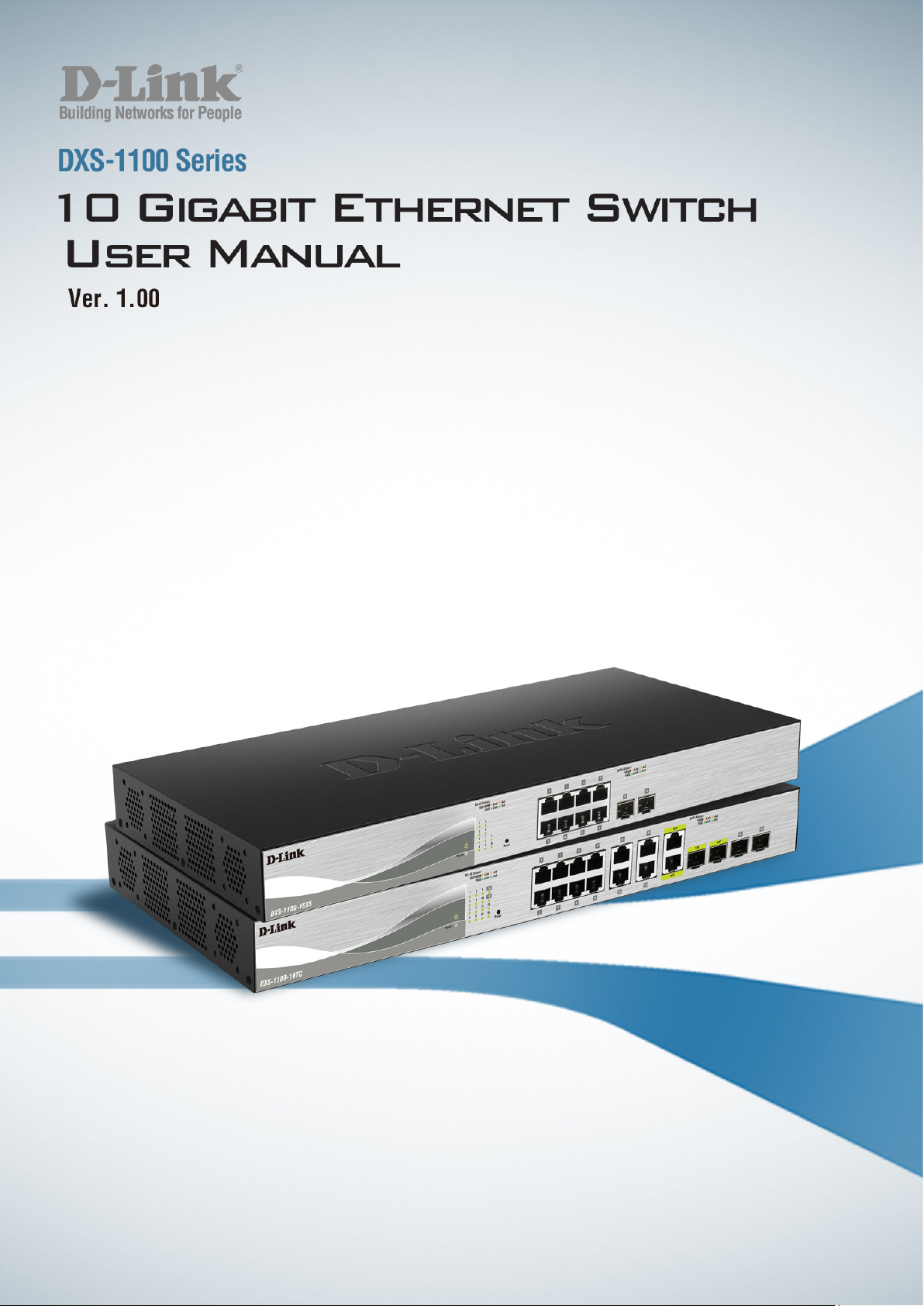
DXS-1100-10TS
The DXS-1100-10TS 10 Gigabit Ethernet Switch supports the following ports:
• Eight 100/1000/1 000 0Mb ps copper Eth er net port s.
• Two 1/10Gbps SFP+ module ports.
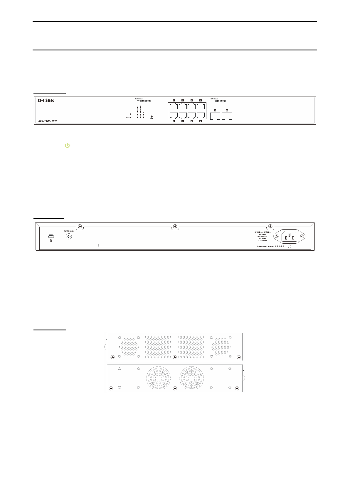
Front Panel
Figure 1.1 – DXS-1100-10TS Front Panel
Power LED
Port Link/Act/Speed LED (1-10): The Link /Act/Speed LED flashes , which indicates a net work link through
the corresponding port. Blinking indicates that the Switch is either sending or receiving data to the port.
When a port has an am ber light, this indicates that the port is running on 10 0M or 1000M. When it has a
green light it is running on 10G.
Fan Err: The LED illuminates red when the fan has run time failure and is brought offline.
Reset: By pressing and holding the Reset button inside the pinhole for 3 to 5 seconds, the Switch will
change back to the default configuration and all changes will be lost.
Rear Panel
: The Power LED lights up when the Switch is connected to a power source.
Figure 1.2 – DXS-1100-10TS Rear Panel
Power: The power port is where to connect the external power adapter.
Security Lock: Provide a Kensingt on-compat ible secur ity lock to be ab le to c onnect to a secur e imm ovable
device. Insert the lock into the notch and turn the key to secure the lock. The lock-and-cable apparatus
should be purchased separately.
Switch GND: U se an electric al grounding wire and connect o ne end of the wire to the Switch GND and the
other end of the wire to an electrical grounding point most commonly found on the switch mounting rack itself.
Side Panels
Figure 1.3 – DXS-1100-10TS Side Panels
Heat Vents: The heat vents are used to dissipate int ernal heat and fac ilitate internal a ir circulation. D o not
block these openings. Leave at least 6 inches of space at the rear and sides of the Switch for proper
ventilation. Without proper heat dissipation and air circulation, system components might overheat which
could lead to system failure or even severely damaged components.
Rack-mounting Screw Holes: T he screw holes are used for attach mounting brackets when installing the
Switch to the rack.
55
Page 13
1 Product Introduction D-Link 10 Gigabit Ethernet Switch User Manual
Fans: Switches in this series have a built-in temperature sensor that will measure the switch’s internal
temperature and then automatically adjust the speed of the fans to either high-speed or low-speed.
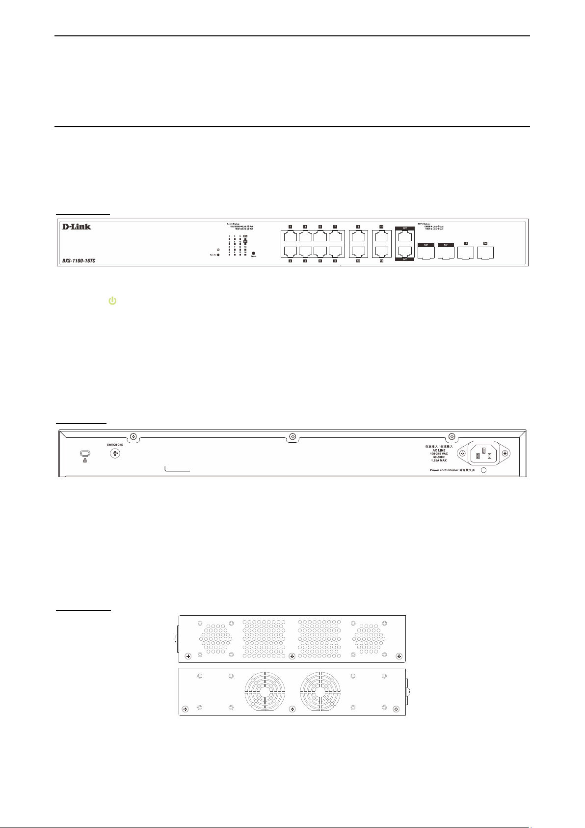
DXS-1100-16TC
The DXS-1100-16TC 10 Gigabit Ethernet Switch supports the following ports:
• Twelve 100/1000/10000Mb ps copper Eth er net por ts .
• Two 100/1000/10000Mbps copper, 1/10Gbps SFP+ combo ports
• Two 1/10Gbps SFP+ module ports.
Front Panel
Figure 1.4 – DXS-1100-16TC Front Panel
Power LED
Port Link/Act/Speed LED (1-16): The Link /Act/Speed LED flashes , which indicates a net work link through
the corresponding port. Blinking indicates that the Switch is either sending or receiving data to the port.
When a port has an am ber light, this indicates that the port is running on 10 0M or 1000M. When it has a
green light it is running on 10G.
Fan Err: The LED illuminates red when the fan has run time failure and is brought offline.
Reset: By pressing and holding the Reset button inside the pinhole for 3 to 5 seconds, the Switch will
change back to the default configuration and all changes will be lost.
Rear Panel
: The Power LED lights up when the Switch is connected to a power source.
Figure 1.5 – DXS-1100-16TC Rear Panel
Power: The power port is where to connect the AC power cord.
Security Lock: Provide a Kensingt on-compat ible secur ity lock to be ab le to c onnect to a secure imm ovable
device. Insert the lock into the notch and turn the key to secure the lock. The lock-and-cable apparatus
should be purchased separately.
Switch GND: U se an electric al grounding wire and connect o ne end of the wire to the Switch GND and the
other end of the wire to an electrical grounding point most commonly found on the switch mounting rack itself.
Side Panels
Figure 1.6 – DXS-1100-16TC Side Panels
Heat Vents: The heat vents are used to dissipate int ernal heat and fac ilitate internal a ir circulation. D o not
block these openings. Leave at least 6 inches of space at the rear and sides of the Switch for proper
66
Page 14

1 Product Introduction D-Link 10 Gigabit Ethernet Switch User Manual
ventilation. Without proper heat dissipation and air circulation, system components might overheat which
could lead to system failure or even severely damaged components.
Rack-mounting Screw Holes: The screw holes are us ed for attach mounting brack ets when installing the
Switch to the rack.
Fans: Switches in this series have a built-in temperature sensor that will measure the switch’s internal
temperature and then automatically adjust the speed of the fans to either high-speed or low-speed.
77
Page 15
2 Hardware Installation D-Link 10 Gigabit Ethernet Switch User Manual
2 Hardware Installation
This chapter provides unpacking and installation information for the Switch.
Step 1: Unpacking
Open the shipping carton and carefully unpack its contents. Please cons ult the packing list located in the
User Manual to make sure all items are present and undamaged.
One D-Link 10 Gigabit Ethernet Switch
One AC power cord
One set of Power cord retainer
Four rubber feet
Screws and two mounting brackets
One Multi-lingual Getting Started Guide
One CD with W eb UI Ref erenc e Guide, Gett ing St arted G uide, and D-Link Net work As sistant Us er
Guide.
If any item is found missing or damaged, please contact the local reseller for replacement.
Step 2: Switch Installation
For safe switch installation and operation, it is recommended that you:
Visually inspect the power cord to see that it is secured fully to the AC power connector.
Make sure that there is proper heat dissipation and adequate ventilation around the switch.
Do not place heavy objects on the switch.
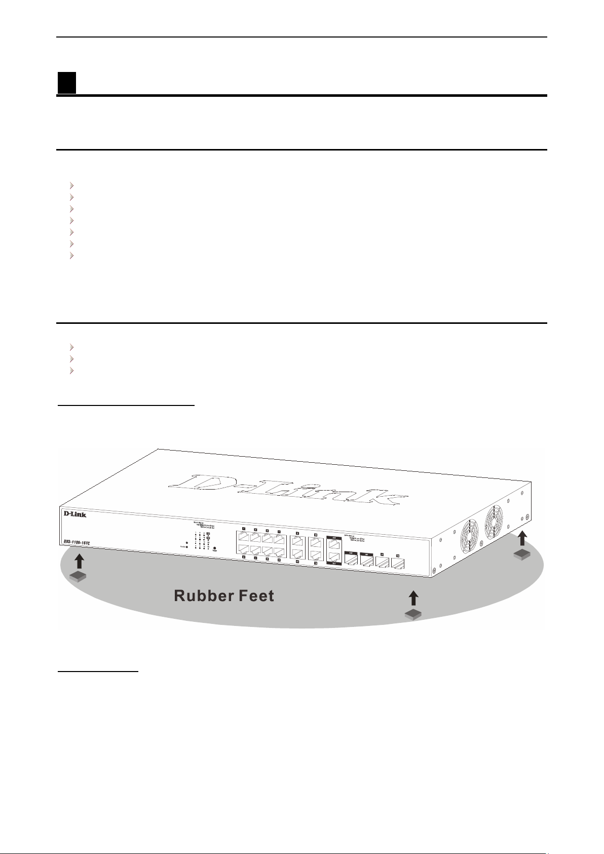
Desktop or Shelf Installation
When installing t he switch on a desktop or shelf, the r ubber feet incl uded with th e device m ust be attached
on the bottom at each corner of the device’s base. Allow enough ventilation space bet ween the device and
the objects around it.
Figure 2.1 – Attach the adhesive rubber pads to the bottom
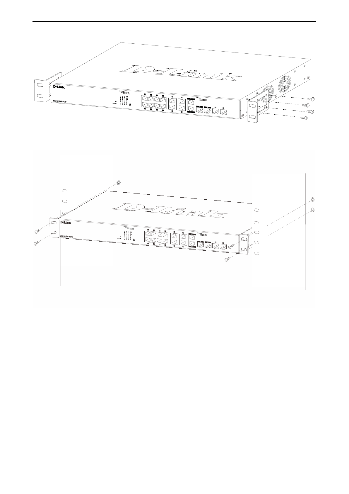
Rack Installation
The switch can be mounted in an EIA s tan dar d s i ze 19-inch rack, which c an be p lac ed in a wiring c loset with
other equipment. T o install, attac h the m ounting brack ets to the s witch’s side p anels (one on each s ide) and
secure them with the screws provided (please note that these brackets are not designed for palm size
switches).
88
Page 16
2 Hardware Installation D-Link 10 Gigabit Ethernet Switch User Manual
Figure 2.2 – Attach the mounting brackets to the Switch
Then, use the screws provided with the equipment rack to mount the switch in the rack.
Figure 2.3 – Mount the Switch in the rack or chassis
Please be aware of following safety Instructions when installing:
A) Elevated Operatin g Ambient - If installe d in a closed or multi-unit rack assembly, the operating am bient
temperature of the r ac k enviro nm ent m a y be greater t han r oom ambient. Therefo re, c onsider atio n sh ould be
given to installing the equipment in an environment compatible with the maximum ambient temperature (Tma)
specified by the manufacturer.
B) Reduced Air F low - Installat ion of the equ ipment in a r ack should be such that the am ount of air flow
required for safe operation of the equipment is not compromised.
C) Mechanical Lo ading - Mounting of th e equipment in the r ac k s hould b e s uc h th at a h a zar dous c ond iti on is
not achieved due to uneven mechanical loading.
D) Circuit Overloading - Consideration should be given to the connection of the equipment to the supply
circuit, and the eff ect that overload ing of the cir cuits m ight have on o vercurrent protection an d suppl y wiring.
Appropriate consideration of equipment nameplate ratings should be used when addressing this concern.
99
Page 17
2 Hardware Installation D-Link 10 Gigabit Ethernet Switch User Manual
E) Reliable Earthing - Reliable earthing of rack-mounted equipment should be maintained. Particular
attention should be given t o supply connec tions ot her than direc t connec tions to the branch cir cuit (e.g. use
of power strips)."
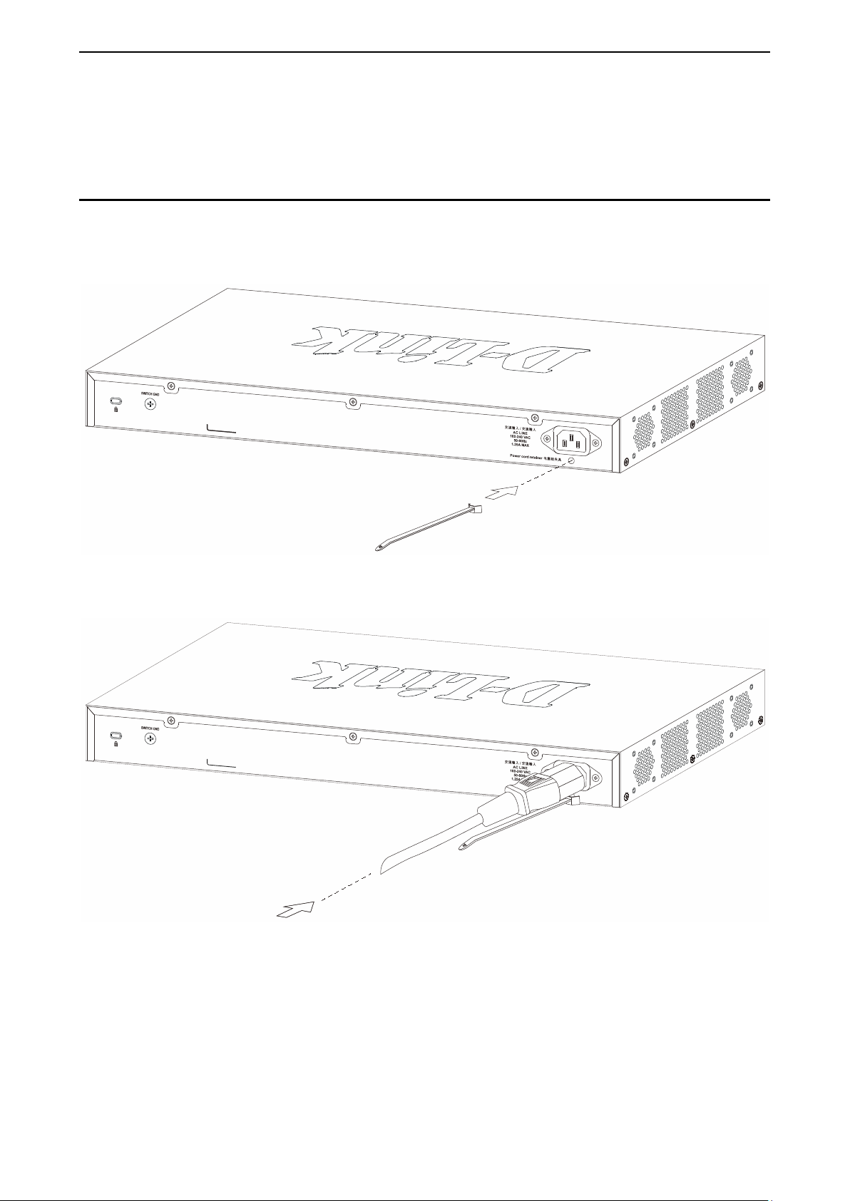
Step 3: Plugging in the AC Power Cord with Power Cord Retainer
To prevent accidenta l removal of the AC power cor d, it is recommended to inst all the power cord retainer
together with the power cord.
A) With the rough side facing down, insert the Tie Wrap into the hole below the power socket.
Figure 2.4 – Insert Tie Wrap to the Switch
B) Plug the AC power cord into the power socket of the Switch.
Figure 2.5 – Connect the power cord to the Switch
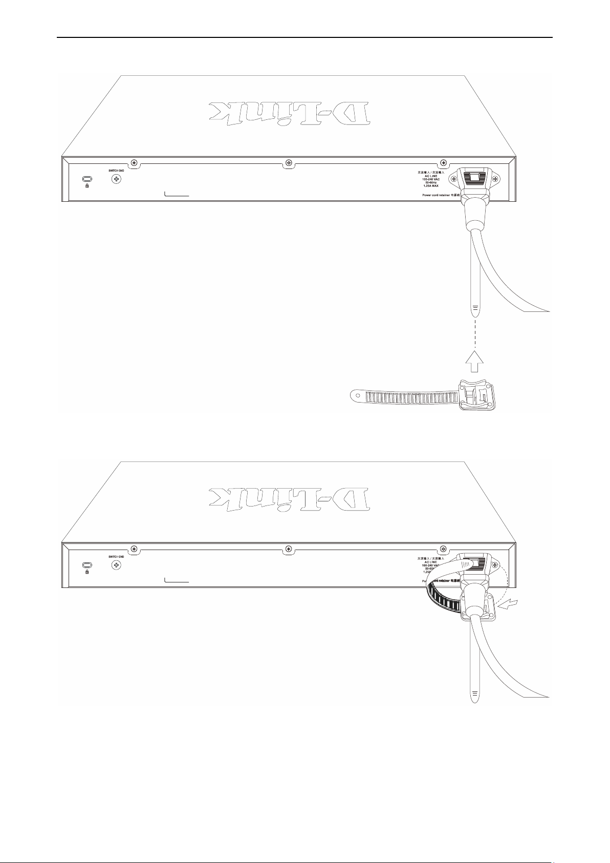
C) Slide the Retainer through the Tie Wrap until the end of the cord.
1100
Page 18
2 Hardware Installation D-Link 10 Gigabit Ethernet Switch User Manual
Figure 2.6 – Slide the Retainer through the Tie Wrap
D) Circle the tie of the Retainer around the power cord and into the locker of the Retainer.
Figure 2.7 – Circle around the power cord
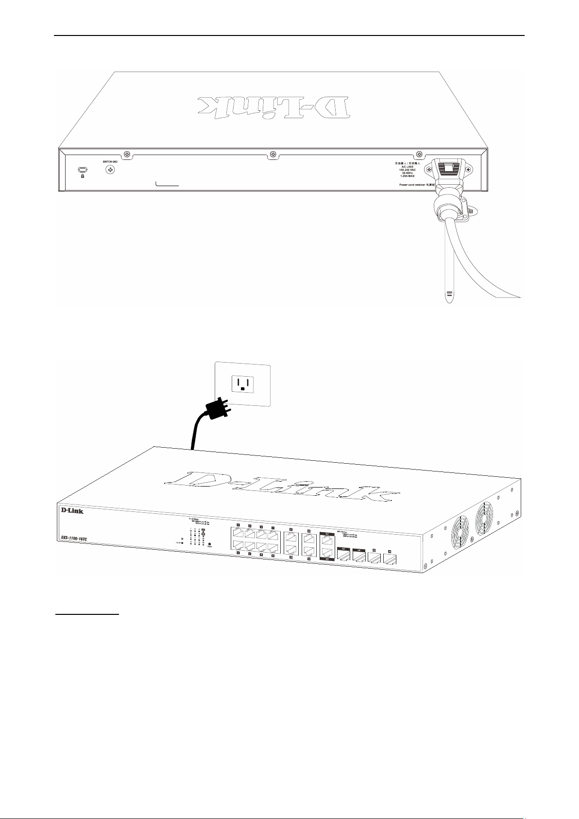
E) Fasten the tie of the Retainer until the power cord is secured.
1111
Page 19
2 Hardware Installation D-Link 10 Gigabit Ethernet Switch User Manual
Figure 2.8 – Secure the power cord
F) Users may now connect the AC po wer cord to an electrical outlet (pref erably one that is grounded and
surge protected).
Figure 2.9 – Plugging the switch into an outlet
Power Failure
As a precaution, the s witch s hould be un plugged in c ase of power failur e. W hen power is r esumed, plug the
switch back in.
1122
Page 20
3 Getting Started D-Link 10 Gigabit Ethernet Switch User Manual
3 Getting Started
This chapter introduces the management interface of the Switch.
Management Options
The D-Link Switch can be managed through any port on the device by using the Web-based Management.
Each switch must be assigned its own IP Address, whic h is used for communication with the W eb-Based
Management or a SN MP network manager. T he PC should have an IP address in the sam e range as the
switch. Each switch can allow up to four users to access the Web-Based Management concurrently.
Please refer to the follo win g ins ta llat ion ins tr uctio ns f or the Web-based Management and the D-Link Netw ork
Assistant (DNA).
Using Web-based Management
After a successful ph ysical ins ta llat ion, you can c o nf ig ure t he S witch, monitor the network stat us, and display
statistics using a web browser.
Supported Web Browsers
The embedded Web-based Management currently supports the following web browsers:
Internet Explorer (version 7 and later)
Firefox
Google Chrome
Safari
Connecting to the Switch
You will need the following equipment to begin the web configuration of your device:
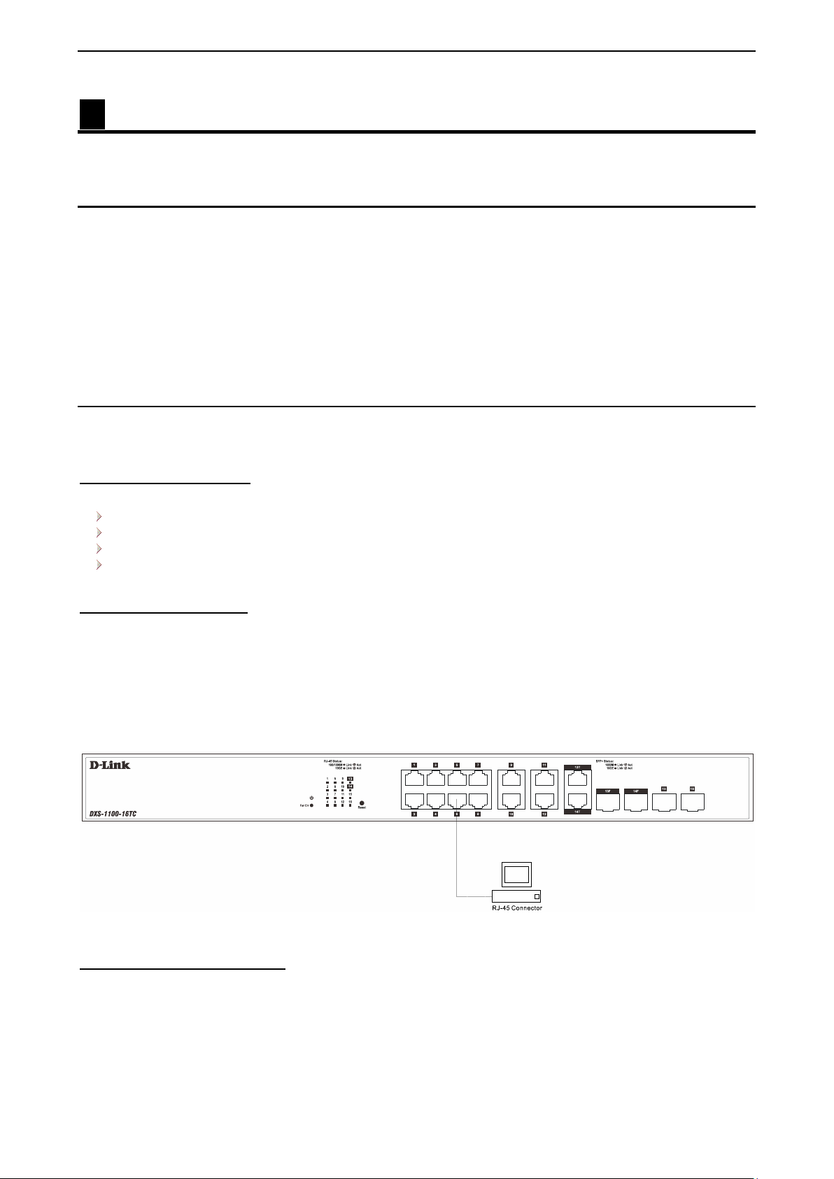
1. A PC with a RJ45 Ethernet connection
2. A standard Ethernet cable
Connect the Ethernet cable to any of the ports on the front panel of the switch and to the Ethernet port on the
PC.
Figure 3.1 – Connected Ethernet cable
Login Web-based Management
In order to login a nd c onf ig ure the switch via an Ethernet conn ec tio n, t he P C must have an I P address in the
same subnet as the s witch. For ex ample, if the switch has an I P ad dres s of 10.90.90.90, the PC should ha ve
an IP address of 10.x.y.z (where x/ y is a number between 0 and 254 and z is a n umber between 1 and 254),
and a subnet mask of 255.0.0.0. Open the web browser and enter 10.90.90.90 (the factory-default IP
address) in the address bar. Then press <Enter>.
1133
Page 21
3 Getting Started D-Link 10 Gigabit Ethernet Switch User Manual
Figure 3.2 – Enter the IP address 10.90.90.90 in the web browser
NOTE: T he Switch's f actory def ault IP ad dress is
10.90.90.90 with a subne t m ask of 255.0.0 .0 and
a default gateway of 0.0.0.0.
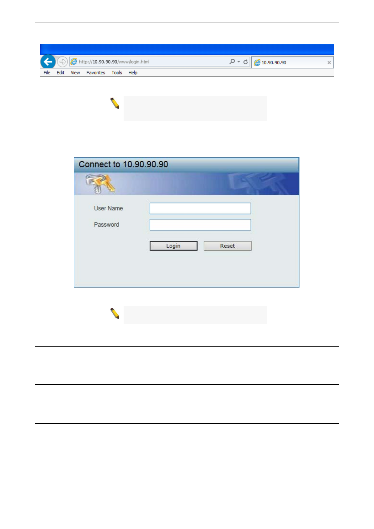
When the following logon dialog box appears, enter the User Name and Password in the cor responding
fields and click Login.
Figure 3.3 – Logon D i a log Box
NOTE: The S witch's factory def ault username is
admin and the default password is admin.
Smart Wizard
After a successful login , the Smart Wizard will guide you through es sential settings of the Switch. Please
refer to the Smart Wizard Configuration section for details.
Web-based Management
By clic k ing the Exit button in the Smart W izard, you wil l enter the W eb-based Management interf ac e. Ple as e
refer to Chapter 4 Configuration
for detailed instructions.
D-Link Network Assistant (DNA)
The D-Link Network Assistant ( DNA) , included in the installation CD, is a progra m that allows administ rators
to quickly discover all D-L ink smart switches and D-Link Discover Pr otocol (DDP) supported devices (f or a
list of supported models, refer to the D-Link Network Assistant (DNA) User Guide), that are in the same
subnet as the PC, co llect traps and log m essages, and provide q uick access to basic conf igurations of the
switch. This tool is only for computers running Windows 7, Vista, XP, or 2000 on both 32/64bit s ys tems.
There are two options for the installation of the DNA; one is thr ough the Autorun program on the ins tallation
CD and the other is manual installation.
1144
Page 22

3 Getting Started D-Link 10 Gigabit Ethernet Switch User Manual
from your PC before installing the latest
NOTE: Please be sure to uninstall any existing
DNA
DNA.
For detailed explanations of the DNA functions, please refer to D-Link Network Assistant (DNA) User Guide.
1155
Page 23
4 Configuration D-Link 10 Gigabit Ethernet Switch User Manual
4 Configuration
The features and functions of the Switch can be configured for optimum use through the Web-based
Management Utility.
Smart Wizard Configuration
After a successf ul login, the Smart W izard will guide you throu gh essential settings of the Switch. If you d o
not plan to change anything, cl ick Exit to leave th e W izard an d enter th e W eb Int erf ace. You can a lso sk ip it
by clicking Ignore the wizard next time for the next time you logon to the Web-based Management.
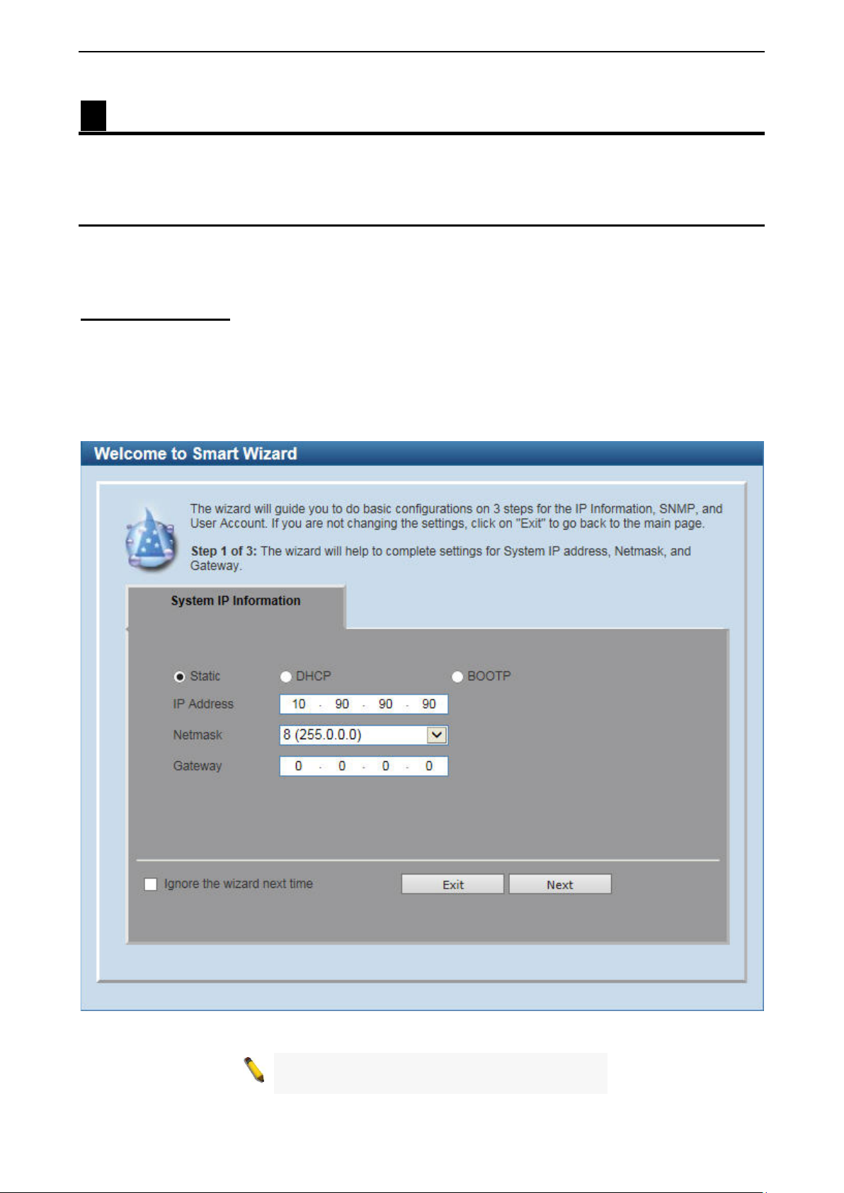
System IP Information
IP Information will guide you to do basic configurations in 3 steps for the IP Information, access password, and SNMP.
Select Static, DHCP or BOOTP, and enter the desired n ew IP Address, se lect the Netmask a nd enter th e
Gateway address, then click the Next button to enter the nex t User Accounts Settings windo w. (No need t o
enter IP Address, Netm ask and Gateway if DHCP and BOOTP ar e selected.) The Smart W izard is for the
quick setting in IPv 4 en vironm ent.
Web-based Management. You can also tick Ignore the wizard next time c heck box to skip wizard setting when the
Switch boots up
.
If you are not changing the settings, click the Exit button to go to the main page of
Figure 4.1 – System IP Information in Smart Wizard
NOTE: The Smart W izard supports quick settings
for IPv4 network.
1166
Page 24
4 Configuration D-Link 10 Gigabit Ethernet Switch User Manual
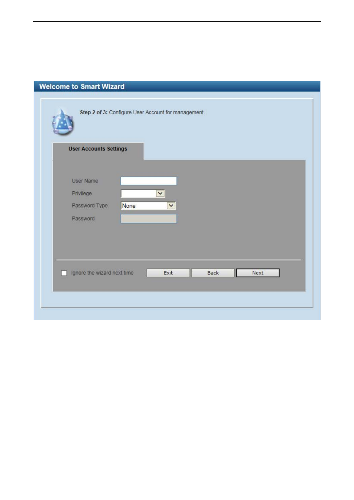
User Accounts Settings Type the desired new username in the User Name field and select the Privilege between User and
Administrator. Select Password Type among None, Plain Text and Encrypted, and type the desired
password in the Password field. Click the Next button to the SNMP window.
Figure 4.2 – User Accounts Settings in Smart Wizard
1177
Page 25
4 Configuration D-Link 10 Gigabit Ethernet Switch User Manual
Changing the system IP address will
disconnect you from the current connection.
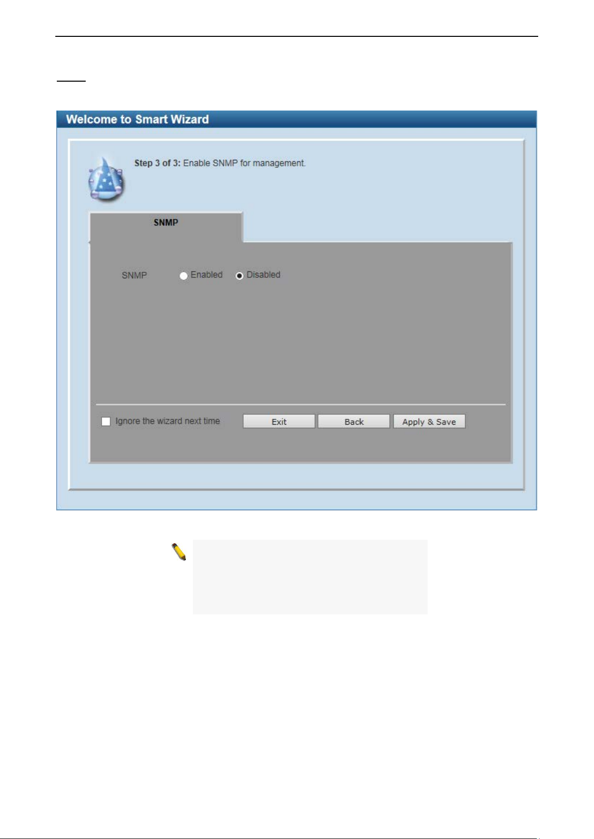
SNMP
The SNMP Sett ing allows you to quickly enable or disable the SNMP func tion. The def ault SNMP Setti ng is
Disabled. Click Enabled and then click Apply & Save to make it effective.
NOTE:
Please enter the correct IP address in the Web
browser again and make sure your PC is in the
same subnet with the switch. See Login Webbased Management for a detailed description.
Figure 4.3 – SNMP in Smart Wizard
1188
Page 26
4 Configuration D-Link 10 Gigabit Ethernet Switch User Manual
If you close the web browser without
Function Tree
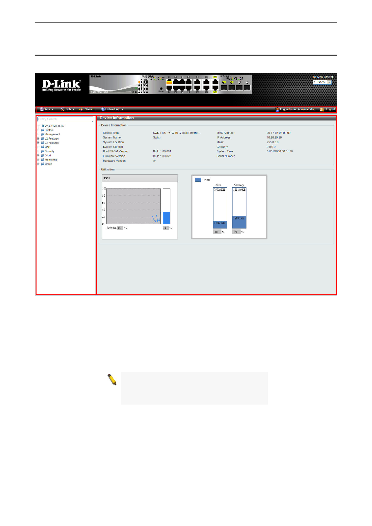
Main Configuration Screen
Tool Bar
Web-based Management
After clicking Exit in Smart Wizard, you will see the screen below:
Figure 4.4 – Web-based Management
The above image is the Web-based Managem ent s cr een. The three main areas ar e the T ool Bar on top, the
Function Tree, and the Main Configuration Screen.
The Tool Bar provides a quick and convenient way for essential utility functions like firmware and
configuration m anagement on the left, an d the userna me with cur rent IP address and the Logout button on
the right. Click Logout to end this session.
NOTE:
clicking th e Logout button f irs t , t hen it will b e s e e n
as an abnormal ex it and the log in session will s till
be occupied.
By choosing different functions in the Function Tree, you can change all the settings in the Main
Configuration Screen. The main configuration scr ee n will sho w the current stat us of your S witc h b y clic k in g
the model name on top of the function tree.
Finally, b y click ing the D-Link logo at the up per-left cor ner of the scr een you will be re directed to the D-Link
website.
1199
Page 27
4 Configuration D-Link 10 Gigabit Ethernet Switch User Manual
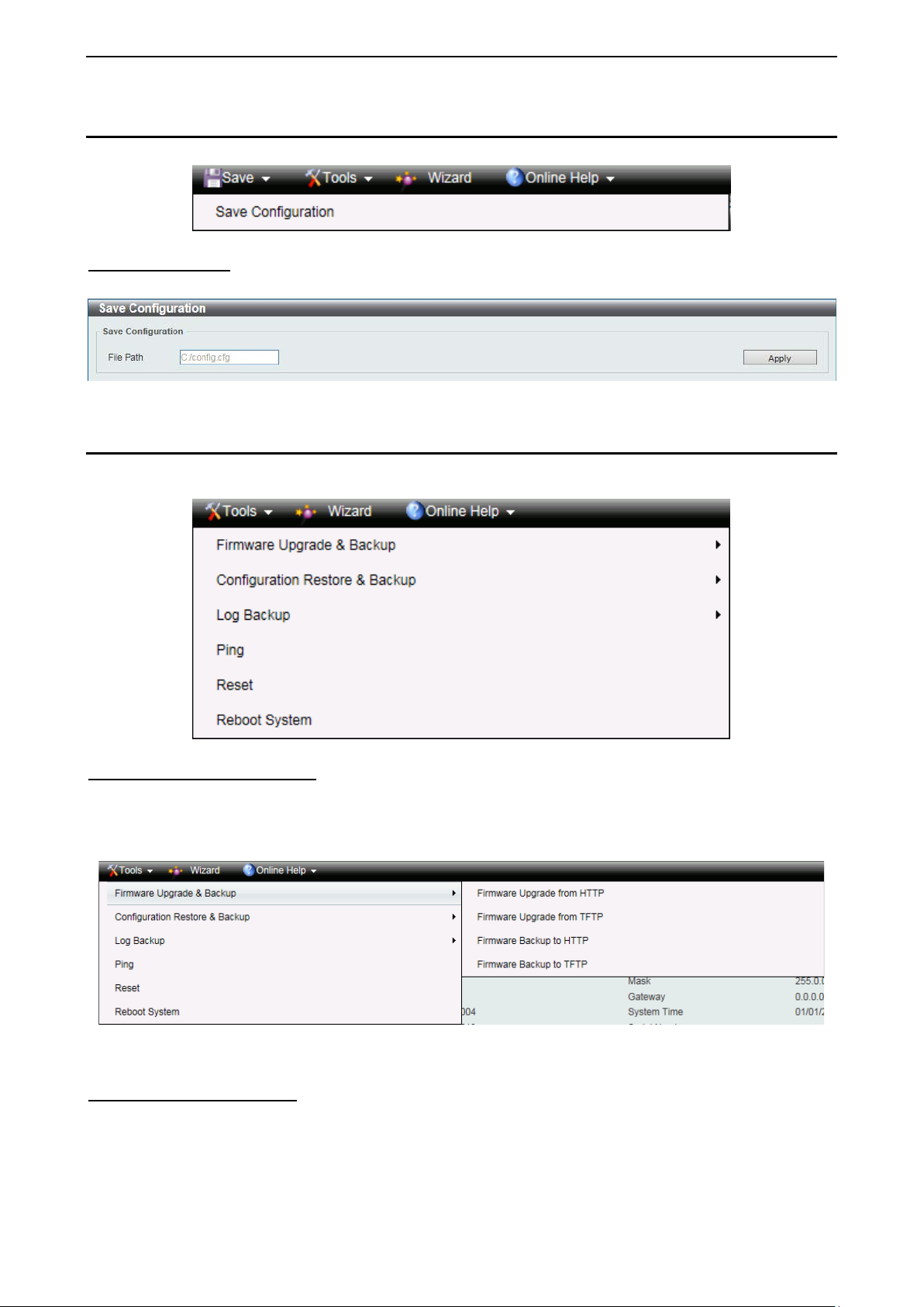
Tool Bar > Save Menu
The Save Menu provides the Save Configuration function.
Figure 4.5 – Save Menu
Save Configuration
Select to save the entire configuration changes you have made to the device to switch’s non-volatile RAM.
Figure 4.6 – Save Configuration
Tool Bar > Tools Menu
The Tools Menu offers global function controls Firmware Upgrade & Backup, Configuration Restore &
Backup, Log Backup, Ping, Reset, and Reboot System.
Figure 4.7 – Tools Menu
Firmware Upgrade and Backup
Allow for the firm ware to b e saved, or for an existing f irmware file to be uploade d to the S witch. The S witch
can only allow having maximum 2 firmware files saved in the File System. Go to Management > File
System t o delete the old firm ware files in order to upgr ade firm ware succes sfull y. The T wo m ethods can be
selected: HTTP or TFTP.
Figure 4.8 – Tools Menu > Firmware Upgrade and Backup
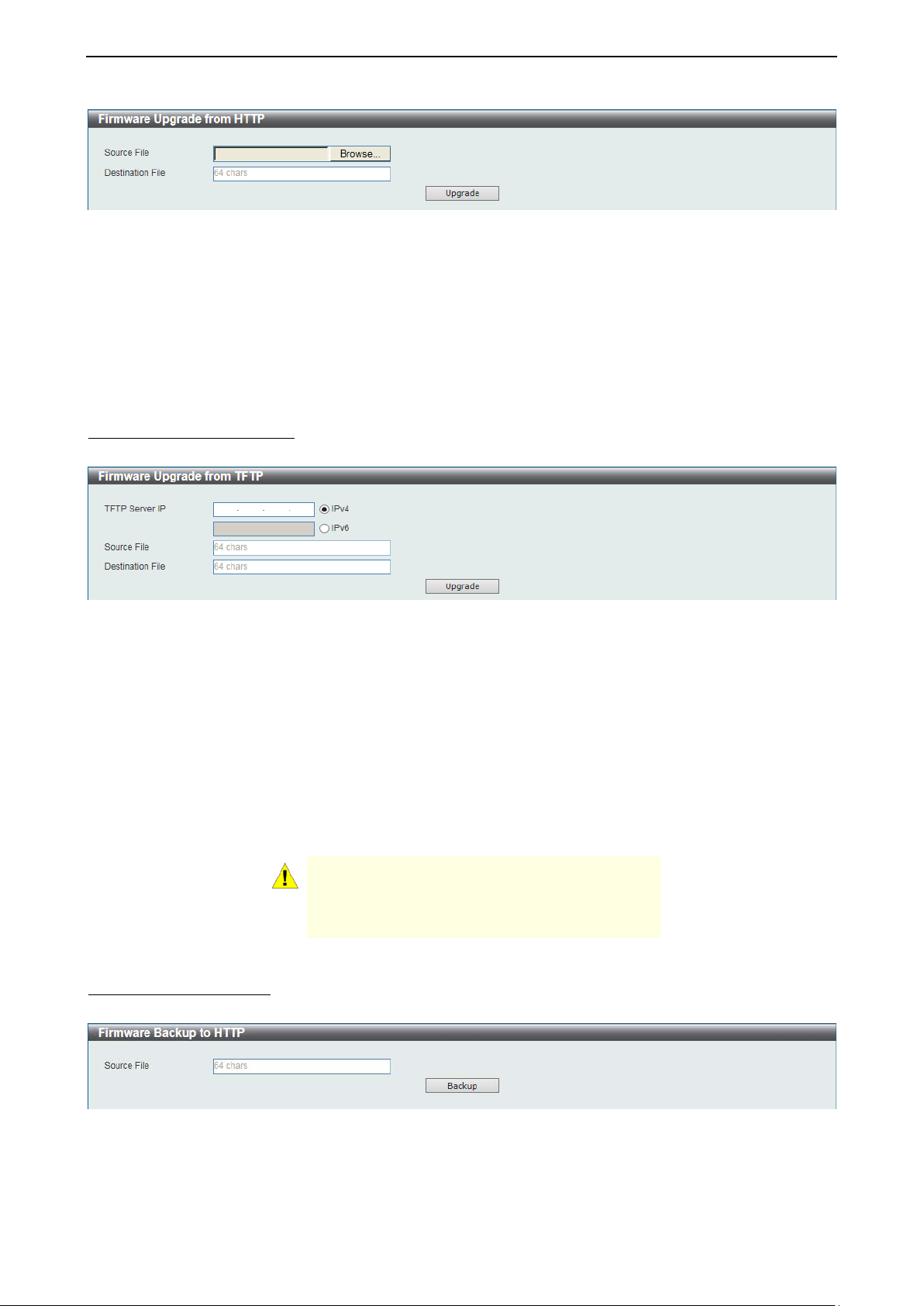
Firmware Upgrade from HTTP
This window is used to upgrade the firmware from HTTP.
2200
Page 28
4 Configuration D-Link 10 Gigabit Ethernet Switch User Manual
Figure 4.9 – Tools Menu > Firmware Upgrade and Backup > Firmwa re U pgrade fro m HTTP
The fields that can be configured are described be lo w:
Source File: Click Browse to browse your inventories for a saved firmware file.
Destination File: Enter th e destination filename and path where the new firm ware should be st ored on the
Switch. This field can be up to 64 characters long.
Click Upgrade after selecting the firmware file you want to restore.
Firmware Upgrade from TFTP
This window is used to upgrade the firmware from TFTP.
Figure 4.10 – Tools Menu > Firmware Upgrade and Backup > Firmware Upgrade from TFTP
The fields that can be configured are described below:
TFTP Server IP: Upgrade the f irmware from a remote T FTP server. Specify TFTP server IP address with
IPv4 or IPv6 address.
Source File: Enter the sour ce filename and path of th e firmware file located o n the TFTP server here. This
field can be up to 64 characters long.
Destination File: Enter th e destination filename and path where the new firm ware should be st ored on the
Switch. This field can be up to 64 characters long.
Click Upgrade after selecting the firmware file you want to restore.
CAUTION: Do not disconnect the PC or remove
the power cord from the S witch until the upgrad e
completes. The S witch m ay cras h if the f irmware
upgrade is incomplete.
Firmware Backup to HTTP
This window is used to back up the firmware to HTTP.
Figure 4.11 – Tools Menu > Firmware Upgrade and Backup > Firmware Backup to HTTP
The fields that can be configured are described below:
Source File: Enter the source filename and path of the firmware f ile located on the Switch here. T his field
can be up to 64 characters long.
2211
Page 29
4 Configuration D-Link 10 Gigabit Ethernet Switch User Manual
Click Backup to save the firmware to your disk.
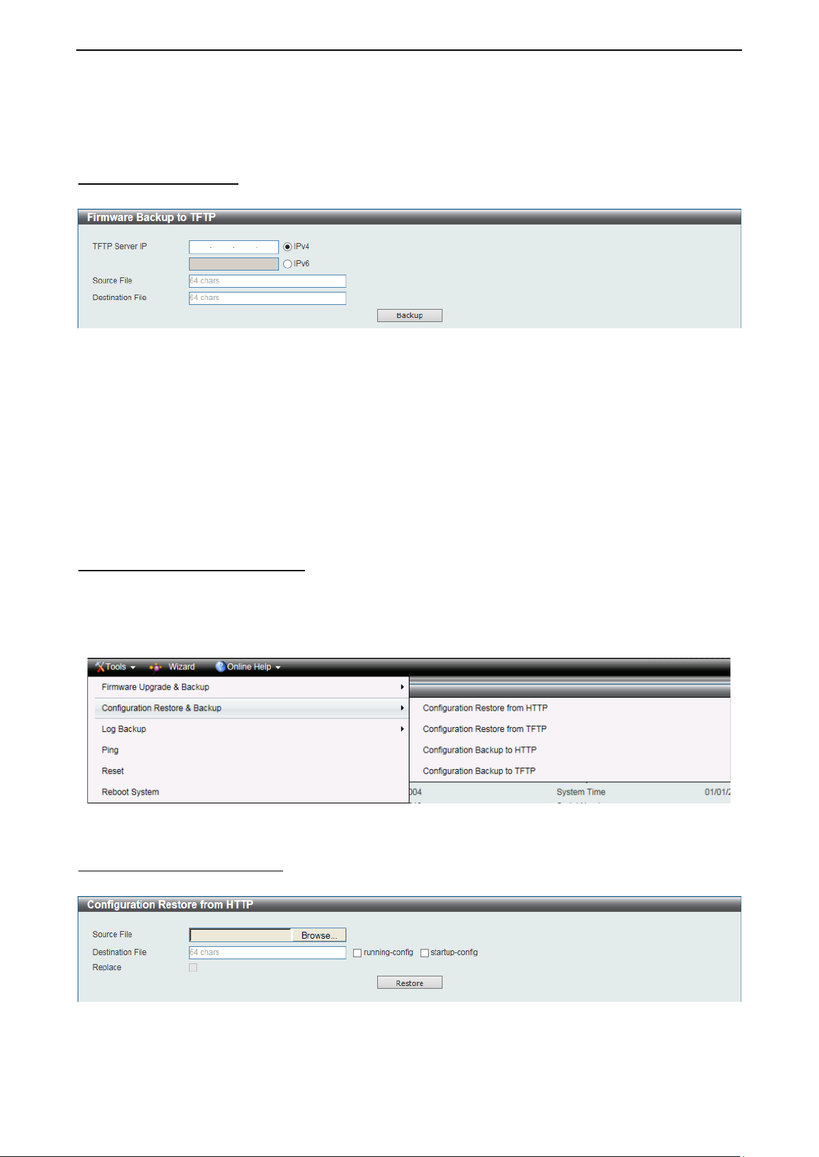
Firmware Backup to TFTP
This window is used to back up the firmware to TFTP.
Figure 4.12 – Tools Menu > Firmware Upgrade and Backup > Firmware Backup to TFTP
The fields that can be configured are described below:
TFTP Serve r IP: Bac kup the firm ware to a remote TFT P server. Specify TFTP server IP address with IPv4
or IPv6 address.
Source File: Enter the source filename and path of the firmware file loc ated on the Switch here. T his field
can be up to 64 characters long.
Destination File: Enter the destination f ilen am e and path where t he fir m ware should be store d o n the T FTP
server. This field can be up to 64 characters long.
Click Backup to save the firmware to the TFTP server.
Configuration Restore and Backup
Allow the current configura tion settings to be saved to a file (not including the pass word), and if necessary,
you can restore the configuration settings from this file. The Switch can only allow having maximum 2
configuration files saved in the File System. Go to Management > File System to delete the old
configuration files in or der to restore configurations suc cessfully. Two methods can be select ed: HTTP or
TFTP.
Figure 4.13 – Tools Menu > Configure Restore and Backup
Configuration Restore from HTTP
This window is used to restore the configuration from HTTP.
Figure 4.14 – Tools Menu > Configure Restore and Backup > Configuration Restore from HTTP
The fields that can be configured are described below:
Source File: Click Browse to browse your inventories for a saved firmware file.
2222
Page 30
4 Configuration D-Link 10 Gigabit Ethernet Switch User Manual
Destination File: Enter th e destination filename and path where the configuration file shou ld be stored on
the Switch. This field can be up to 64 characters long. Select the running-config option to restore and
overwrite the running configuration file on the Switch. Select the startup-config option to restore and
overwrite the start-up configuration file on the Switch.
Replace: Replace the current running configuration.
Click Restore after selecting the backup settings file you want to restore.
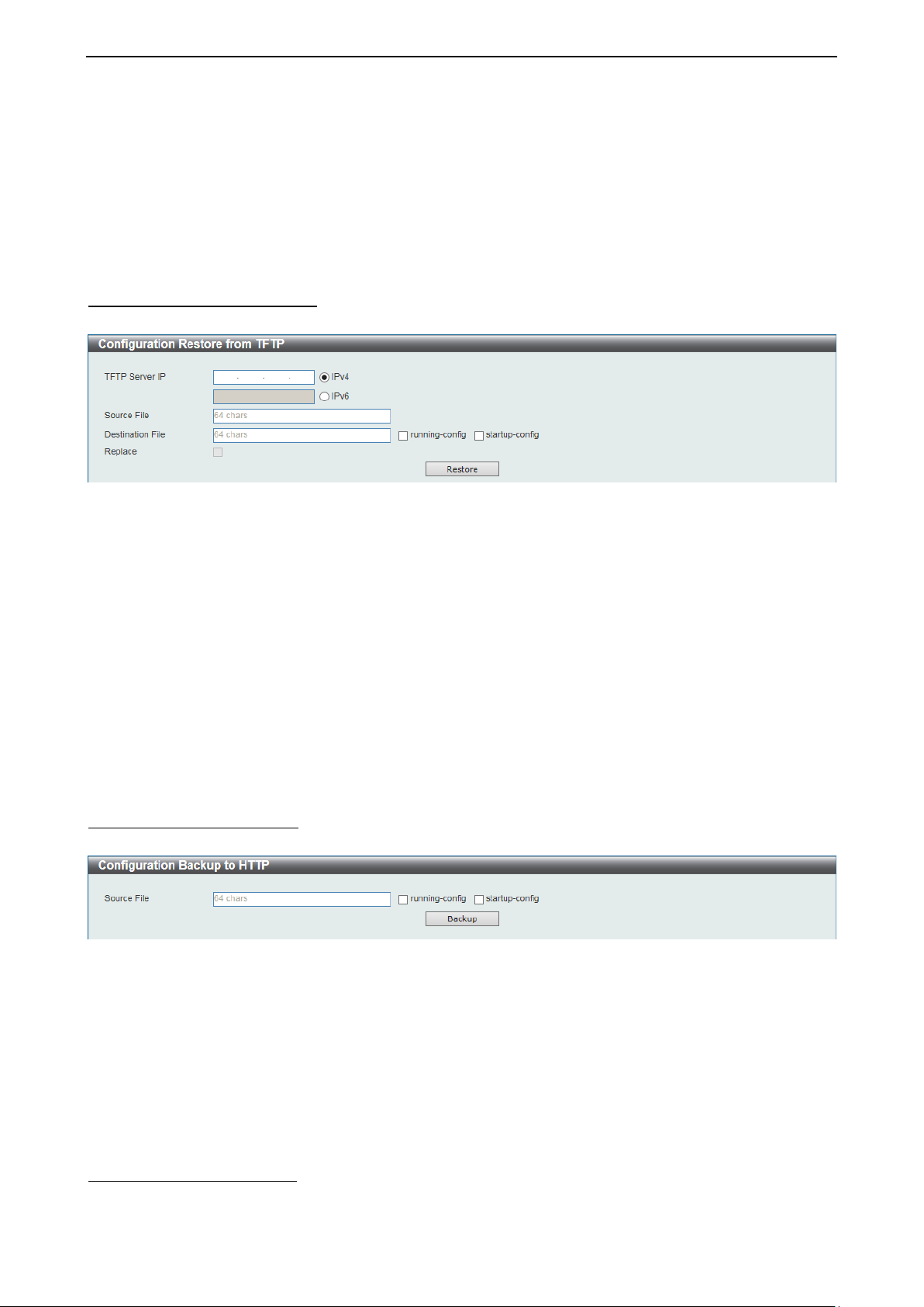
Configuration Restore from TFTP
This window is used to restore the configuration from TFTP.
Figure 4.15 – Tools Menu > Configure Restore and Backup > Configuration Restore from TFTP
The fields that can be configured are described below:
TFTP Server IP: Restore the configuration from a remote TFTP server. Specify TFTP server IP address with
IPv4 or IPv6 address.
Source File: Enter the source filenam e and path of the configuration f ile located on the T FTP server here.
This field can be up to 64 characters long.
Destination File: Enter th e destination filename and path where the configuration file shou ld be stored on
the Switch. This field can be up to 64 characters long. Select the running-config option to restore and
overwrite the running configuration file on the Switch. Select the startup-config option to restore and
overwrite the start-up configuration file on the Switch.
Replace: Replace the current running configuration.
Click Restore after selecting the backup settings file you want to restore.
Configuration Backup to HTTP
This window is used to back up the configuration to HTTP.
Figure 4.16 – Tools Menu > Configure Restore and Backup > Configuration Backup to HTTP
The fields that can be configured are described below:
Source File: Enter the sour ce filename and path of the configuration file located on the Switch here. This
field can be up to 64 charac ters long. S elect the running-config option to back up the running c onfiguratio n
file from the Switch. Select the startup-config option to back up the start-up configuration file from the
Switch.
Click Backup to save the current settings to your disk.
Configuration Backup to TFTP
This window is used to back up the configuration to TFTP.
2233
Page 31

4 Configuration D-Link 10 Gigabit Ethernet Switch User Manual
Figure 4.17 – Tools Menu > Configure Restore and Backup > Configuration Backup to TFTP
The fields that can be configured are described below:
TFTP Server IP: Back up the configuration from a remote TFTP server. Specify TFTP server IP address with
IPv4 or IPv6 address.
Source File: Enter the sour ce filename and path of the co nfiguration file located on t he switch here. This
field can be up to 64 charac ters long. Sel ect the running-config option to back up the running c onfiguratio n
file from the Switch. Select the startup-config option to back up the start-up configuration file from the
Switch.
Destination File: Enter th e destination filename and path where the configuration file shou ld be stored on
the TFTP server. This field can be up to 64 characters long.
Click Backup to save the current settings to the TFTP server.
Log Backup Allow the logs to be saved to HTTP or TFTP.
Figure 4.18 – Tools Menu > Log Backup
Log Backup to HTTP
This window is used to back up the logs to HTTP.
Figure 4.19 – Tools Menu > Log Backup > Log Backup to H TTP
The fields that can be configured are described below:
Log Type: Select the log type that will be b acked up to the local PC using HTTP. W hen the System Log
option is selected, th e s ystem log wil l be b ack ed up. When the Attack Log is se lected , the attac k log will be
backed up.
Click Backup to save the current settings to your disk.
Log Backup to TFTP
This window is used to back up the logs to TFTP.
2244
Page 32

4 Configuration D-Link 10 Gigabit Ethernet Switch User Manual
Figure 4.20 – Tools Menu > Log Backup > Log Backup to TFTP
The fields that can be configured are described below:
TFTP Server I P: Back up the log from a remote T FTP server. Specif y TFTP server IP address with IPv4 or
IPv6 address.
Destination File: Enter th e destination f ilename and path where the log f ile should be store d on the TFT P
server. This field can be up to 64 characters long.
Log Type: Select the log type that will be back ed up to the TFT P server. When the System Log optio n is
selected, the system log will be backed up. W hen the Attack Log is selected, the attack log will be backed
up.
Click Backup to save the current settings to the TFTP server.
Ping
Ping is a sm all program that sen ds ICMP Echo packets to the I P address you s pecif y. The desti nation n ode
then responds to or “echoes” the packets sent from the Switch. This is very useful to verify connectivity
between the Switch and other nodes on the network.
Figure 4.21 – Tools Menu > Ping
The fields that can be configured are described below:
Target IPv4 Address / Target IPv6 Address: Enter an IPv4 or IPv6 address to be pinged.
Ping Times: Enter th e number of times desired to a ttempt to Ping the IPv4 or IP v6 address. Users may
enter a number of times between 1 and 255. Tick Infinite to keep sending ICMP Echo packets to the
specified IPv4 or IPv6 address until the program is stopped.
Timeout: Select a tim eout period between 1 an d 99 seconds for this Ping mess age to reach its destinat ion.
If the packet fails to find the IPv4 or IPv6 address in this specified time, the Ping packet will be dropped.
Click Start to initiate the Ping Test for each individual section.
After clicking Start, the Ping Result section will appear:
2255
Page 33

4 Configuration D-Link 10 Gigabit Ethernet Switch User Manual
Figure 4.22 –Ping Result
Click Stop to halt the Ping Test.
Click Back to return to the IPv4 or IPv6 Ping section.
Reset
Provide a safe reset option for the Switch.
Figure 4.23 – Tools Menu > Reset
Select the The Switch will be reset to its factory defaults including IP address, and then will save,
reboot. option to reset the Switch’s configuration to its factory default settings.
Select the The Switch will be reset to its factory defaults except IP addre ss, an d t hen will save, reboot
option to reset the Switch’s configuration to its factory default settings. This option will exclude the IP
address from being changed.
Select the The Switch will be reset to its factory defaults including IP address option to reset the
Switch’s configuration to its factory default settings.
Click Apply to initiate the factory default reset and reboot the Switch.
Reboot System Provide a safe way to reboot the system. Click Yes and Apply to restart the Switch.
Figure 4.24 – Tools Menu > Reboot Device
Tool Bar > Wizard
By clicking the Wizard button, you can return to the Smart Wizard if you wish to make any changes there.
2266
Page 34

4 Configuration D-Link 10 Gigabit Ethernet Switch User Manual
Tool Bar > Online Help
The Online Help provides two ways of online support: D-Link Support Site will lead you to the D-Link
website where you c an find online resources s uch as updated firmware im ages; User Guide ca n offer an
immediate reference for the feature definition or configuration guide.
Figure 4.25 – Online Help
2277
Page 35

4 Configuration D-Link 10 Gigabit Ethernet Switch User Manual
Function Tree
All configuration options o n the S witc h ar e acc es sed t h rough th e F unc t ion T r ee. Cl ick the setup item that you
want to configure. The following sections provide more detailed description of each feature and function.
Figure 4.26 – Available settings in the Function Tree
Device Information
In this window, the Device Information, CPU, a nd Used status are d isplayed. It appears automaticall y when
you log in the Switch.
2288
Page 36

4 Configuration D-Link 10 Gigabit Ethernet Switch User Manual
Figure 4.27 – Device Information
System > System Information Settings
The System Information Settings allows the user to configure a System Name, System Location, and System
Contact to aid in defining the Switch.
Figure 4.28 – System > Syste m Information Settings
The fields that can be configured are described below:
System Name: Enter a s ystem name for the Switch, if so desired. This nam e will identify it in the Switch
network.
System Location: Enter the location of the Switch, if so desired. T his string can be up to 255 characters
long.
System Contact: Enter a contact name for the Switc h, if s o desir e d. This string ca n b e u p to 25 5 c haracters
long.
System > Peripheral Settings
This window is used to configure the environment trap settings and environment temperature threshold
settings.
Figure 4.29 – System > Peripheral Settings
2299
Page 37

4 Configuration D-Link 10 Gigabit Ethernet Switch User Manual
The fields that can be configured are described be lo w:
Fan Trap: Enable or disable the fan trap state for warning fan event (fan failed or fan recover).
Thermal: Select the thermal sensor ID.
High Threshold: Enter the high thr eshold value of the warni ng temper ature setting. T he range is from -100
to 200 Celsius degree. Tick Default to return to the default value. The default value is 79.
Low Threshold: Enter the low thr es ho ld val ue of t he war ning temperature sett ing. T he r an ge is from -100 to
200 Celsius degree. Tick Default to return to the default value. The default value is 11.
Click Apply to accept the changes made for each individual section.
System > Port Configuration > Port Settings
This window is used to view and configure the Switch’s port settings.
Figure 4.30 – System > Port Configuration > Port Settings
The fields that can be configured are described below:
From Port / To Port: Select the appropriate port range used for the configuration here.
Medium Type: If configuring the Combo ports, this defines the type of transport medium to be used.
State: Select this option to enable or disable the physical port here.
MDIX: Select the Medium Dependent Interface Cross over (MDIX) option her e. This is only available when
the copper port is selected. Options to choose from are Auto, Normal, and Cross.
Auto - Select this option for auto-sensing of the optimal type of cabling.
Normal - Select this opti on for normal cabli ng. If th is o ptio n is s e lec te d, the p or t is i n t he MDIX mode
and can be connected to a PC’s NI C using a straight -through cable or a p ort (in the MDIX m ode) on
another switch through a cross-over cable.
Cross - Select this opt ion for c ross cabling. If t his option is s electe d, the port is in the MDI m ode an d
can be connected to a port (in the MDIX mode) on another switch through a straight cable.
3300
Page 38

4 Configuration D-Link 10 Gigabit Ethernet Switch User Manual
Flow Control: Select to either turn flo w control On or Off here. Ports configured f or full-duplex use 8 02.3x
flow control, half-duplex ports use back-pres sure flow control, and Auto ports use an automatic s election of
the two.
Duplex: Select the duplex mode used here. Options to choose from are Auto, and Full.
Speed: Select t h e p ort s p e ed option here. T his opt io n wil l manually force the connected on t he s elec t ed port
to only connect at the spe e d s pecif ied h er e. O pt ions to c hoos e f r om are Auto, 100M, 1000M, 1000M Master,
1000M Slave, and 10G. The Switch allows users to configure two types of gigabit connections; 1000M
Master and 1000M Slave which ref er to connections r unning a 1000BASE-T cable for connectio n between
the Switch port an d another device capabl e of a gi gabit connect ion. The m aster setting ( 1000M Mast er) will
allow the port to advert ise capabilities related to duplex, speed and physic al layer type. The mas ter setting
will also determine the master and slave relationship between the two connected physical layers. This
relationship is necessary for establishing the timing control between the two physical layers. The timing
control is set on a mas ter ph ysica l la yer b y a l oc al source. The slave settin g (10 00M Slave) uses loop t im ing,
where the tim ing comes from a data stream received from the m aster. If one connection is se t for 1000M
Master, the other side of the conn ection m us t be set f or 100 0M Slav e. An y other conf igurat ion wi ll resu lt in a
link down status for both ports.
Capability Advertised: W hen the Speed is set to Auto and the copper port is selected, thes e capabilities
are advertised during auto-negotiation.
Description: Enter a 64 characters description for the corresponding port here.
Click Apply to accept the changes made.
System > Port Configuration > Port Status
This window is used to view the Switch’s physical port status and settings.
Figure 4.31 – System > Port Configuration > Port Sta tus
System > Port Configuration > Error Dis ab le Set t ings
This window is used to configure the sending of SNMP notifications for error disable state.
3311
Page 39

4 Configuration D-Link 10 Gigabit Ethernet Switch User Manual
Figure 4.32 – System > Port Configuration > Error Disable Settings
The fields that can be configured are described below:
Asserted: Select this option to enable or disable the notifications when entering into the error disabled state.
Cleared: Select this option to enab le or disa ble the notifications when exiting from the error disabled state.
Notification Rate: Enter the num ber of traps per m inute. The pac kets that exc eed the rate will be dropp ed.
The value is between 0 and 1000.
ErrDisable Cause: Select the error disable causes here. Options to choose from are All, Port Security,
Storm Control, and Loopback Detect.
State: Select this opt ion to enable or disable the auto-recovery for an error port caused by the sp ecified
cause.
Interval: Enter the time between 5 and 86400 seconds to recover the port.
Click Apply to accept the changes made for each individual section.
System > Port Configuration > Jumbo Frame
This window is used to view and configur e the Jumbo F rame size and sett ings. The Switch su pports jumbo
frames. Jumbo frames are Ethernet frames with more than 1,536 bytes of payload. The Switch supports
jumbo frames with a maximum frame size of up to 9,216 bytes.
3322
Page 40

4 Configuration D-Link 10 Gigabit Ethernet Switch User Manual
Figure 4.33 – System > Port Configuration > Jumbo Frame
The fields that can be configured are described below:
From Port / To Port: Select the appropriate port range used for the configuration here.
Maximum Receive Frame Size: Enter the maximum receive frame size value here. This value must be
between 64 and 9216 bytes. By default, this value is 1536 bytes.
Click Apply to accept the changes made.
System > System Log > System Log Settings
This window is used to vie w and c onf ig ure the system’s log settings . System logs record and manage even ts ,
as well as report errors and informational messages.
Figure 4.34 – System > System Log > System Log Settings
The fields that can be configured are described below:
Source Interface State: Enable or disable the source interface’s global state.
Buffer Log State: Enable or disable the buffer log’s global state here. Options to choose from are Enab le,
Disabled, and Default . When selecting the D efault option, the buff er log’s global state will f ollow the default
behavior.
Severity: Select the severity val ue of the t ype of inf orm ation that will b e logged. Options to cho ose fr om are
0 (Emergencies), 1 (Alerts), 2 (Critical), 3 (Errors), 4 (Warnings), 5 (Notifications), 6 (Informational),
and 7 (Debugging).
Discriminator Name: Enter the discriminator name used here. This name can be up to 15 characters long.
3333
Page 41

4 Configuration D-Link 10 Gigabit Ethernet Switch User Manual
Write Delay: Enter the interval for periodic writing of the logging buffer to FLASH. This value must be
between 0 and 65535 sec onds. By defaul t, this value is 300 sec onds. Tick Infinite to disa ble the wri te dela y
feature.
Click Apply to accept the changes made for each individual section.
System > System Log > System Log Discriminator Settings
This window is used to view and configure the system log’s discriminator settings.
Figure 4.35 – System > System Log > System Log Discriminator Settings
The fields that can be configured are described below:
Discriminator Name: Enter the discriminator name here. This name can be up to 15 characters long.
Action: Sel ect the facility’s behavi or option and the type of facilit y that will be associated with the sel ected
behavior here. Behavior options to choose from are Drops and Includes.
Severity: Select th e severity behavior option and the va lue of the type of information that will be logged.
Behavior options to choose from are Drops and Includes. Severity value options to choose from are 0
(Emergencies), 1 (Alerts), 2 (C ritical), 3 (Errors), 4 (Warnings) , 5 (Notifications), 6 (Informational), and
7 (Debugging).
Click Apply to accept the changes made.
Click Delete to remove the specified entry.
System > System Log > System Log Server Settings
This window is used to view and configure system log’s server settings.
Figure 4.36 – System > System Log > System Log Server Settings
The fields that can be configured are described below:
Host IPv4 Address: Specifies the IPv4 address of the system log server.
Host IPv6 Address: Specifies the IPv6 address of the system log server.
3344
Page 42

4 Configuration D-Link 10 Gigabit Ethernet Switch User Manual
UDP Port: Specifies the U DP port to which the s erver logs are sent. This value must be 514, or between
1024 and 65535. The default value is 514.
Severity: Select the sever ity value of the type of inform ation that w ill be logg ed. Options to choose from are
0 (Emergencies), 1 (Alerts), 2 (Critical), 3 (Errors), 4 (Warnings), 5 (Notifications), 6 (Informational),
and 7 (Debugging).
Facility: Select the facility value here. Options to choose from are 0 to 23.
Discriminator Name: Enter the discriminator name here. This name can be up to 15 characters long.
Click Apply to accept the changes made.
Click Delete to remove the specified entry.
System > System Log > System Log
This window is used t o vie w and c le ar the system log. The maximum number of entries that will be displa yed
in this table is 1,000. The index number can go up to 90,000. When this log is full, older entries will be
removed and replaced by newer ones.
Figure 4.37 – System > System Log > Sys tem Log
Click Clear Log to clear the system log entries displayed in the table.
Enter a page number and click Go to navigate to a specific page when multiple pages exist.
System > System Log > System Attack Log
This window is used to view and clear the system attack log. The m aximum number of entries that will be
displayed in this table is 1,000. The index number can go up to 90,000. When this log is full, older e ntr ies wil l
be removed and replaced by newer ones.
Figure 4.38 – System > System Log > System Attack Log
Click Clear Attack Log to clear the system attack log entries displayed in the table.
System > Time and SNTP > Clock Settings
The Simple Network Time Protocol (SNTP) is a protocol for synchronizing computer clocks through the
Internet. It provides comprehensive mechanisms to access national time and frequency dissemination
3355
Page 43

4 Configuration D-Link 10 Gigabit Ethernet Switch User Manual
services, organize th e SNTP subnet of servers and c lients, and adjust th e system clock in each participant .
This window is used to configure the time settings for the Switch.
Figure 4.39 – System > Time and SNTP > Clock Settings
The fields that can be configured are described below:
Time (HH MM:SS): Enter the current time in hours, minutes, and seconds.
Date (DD/MM/YYYY): Enter the current day, month, and year to update the system clock.
Click Apply to accept the changes made.
System > Time and SNTP > Time Zone Settings
This window is used to configure time zones and Daylight Savings Time settings for SNTP.
Figure 4.40 – System > Time and SNTP > Time Zone Settings
The fields that can be configured are described below:
Summer Time State: Select the summer time setting. Options to choose from are Disabled, Recurring
Setting, and Date Setting.
Disabled - Select to disable the summer time setting.
Recurring Setting - Select to conf igure the sum mer tim e that should s tart and e nd on the spec ified
week day of the specified month.
3366
Page 44

4 Configuration D-Link 10 Gigabit Ethernet Switch User Manual
Date Setting - Select to configure the summer time that should start and end on the specified date of
the specified month.
Time Zone: Select to specify your local time zone’s offset from Coordinated Universal Time (UTC).
From: Week of the Month: Select week of the month that summer time will start.
From: Day of the Week: Select the day of the week that summer time will start.
From: Month: Select the month that summer time will start.
From: Time (HH:MM): Select the time of the day that summer time will start.
To: Week of the Month: Select week of the month that summer time will end.
To: Day of the Week: Select the day of the week that summer time will end.
To: Month: Select the month that summer time will end.
To: Time (HH:MM): Select the time of the day that summer time will end.
Offset: Enter t he number of minutes to add during summ er time. The default value is 60. T he range of thi s
offset is 30, 60, 90 and 120.
From: Date of the Month: Select date of the month that summer time will start.
From: Month: Select the month that summer time will start.
From: Year: Enter the year that the summer time will start.
From: Time (HH:MM): Select the time of the day that summer time will start.
To: Date of the Month: Select date of the month that summer time will end.
To: Month: Select the month that summer time will end.
To: Year: Enter the year that the summer time will end.
To: Time (HH:MM): Select the time of the day that summer time will end.
Offset: Enter t he number of minutes to add during summ er time. The default value is 60. T he range of thi s
offset is 30, 60, 90 and 120.
Click Apply to accept the changes made.
System > Time and SNTP > SNTP Settings
This window is used to configure the time settings for the Switch.
Figure 4.41 – System > Time and SNTP > SNTP Settings
The fields that can be configured are described below:
SNTP State: Select this option to enable or disable SNTP.
Poll Interval: Enter the synchronizing interval in seconds. The value is from 30 to 99999 seconds. The
default interval is 720 seconds.
IPv4 Address: Enter the IP address of the SNTP server which provides the clock synchronization.
IPv6 Address: Enter the IPv6 address of the SNTP server which provides the clock synchronization.
Click Apply to accept the changes made.
3377
Page 45

4 Configuration D-Link 10 Gigabit Ethernet Switch User Manual
Click Delete to remove the specified entry.
System > Time Range
This window is used to view and configure the time range settings.
Figure 4.42 – System > Time Range
The fields that can be configured are described below:
Range Name: Enter the name of the time range. This name can be up to 32 characters long.
From: Week / To: Week: Select the start ing and ending days of the week that will be used for th is time
range. Tick Daily to use t hi s time range for every day of the week. Tick End Weekday to use t h is time range
from the starting day of the week until the end of the week, which is Sunday.
From: Time (HH:MM) / To: Time (HH:MM): Select th e starting a nd ending t ime of the da y th at will be used
for this time range . The firs t drop-down m enu selects the hour an d the sec ond drop-do wn menu se lects the
minute.
Click Apply to accept the changes made.
Click Find to locate a specific entry based on the information entered.
Click Delete Period ic to delete the periodic entry.
Click Delete to remove the specified entry.
Enter a page number and click Go to navigate to a specific page when multiple pages exist.
Management > User Accounts Settings
This window is use d to create and configure the user accoun ts. The active user accoun t sessions can be
viewed.
There are two user account privilege available, User and Administrator:
• User - This user acc ount le ve l has the lo w er pr iority of the user accounts. T he pur pos e of this t ype of
user account level is for basic system checking.
• Administrator - T his adm inistrator us er acc ount le vel can m onitor a ll s ystem inform ation and c hange
any of the system configuration settings expressed in this guide.
Figure 4.43 – Management > User Accounts Settin gs (User Management Settings)
3388
Page 46

4 Configuration D-Link 10 Gigabit Ethernet Switch User Manual
The fields that can be configured are described below:
User Name: Enter the user account name here. This name can be up to 32 characters long.
Privilege: Select the privilege level for this account.
Password Type: Select the pas sword type for this us er account here. Options to cho ose from are None,
Plain Text and Encrypted. When selecting Encr ypted, the password will not be encr ypted from the plain-
text format to the encrypted format. Instead, the encrypted password must be entered.
Password: After selecting Plain Text or Encrypted as the Password Type, enter the password for this
user account here.
Click Apply to accept the changes made.
Click Delete to remove the specified entry.
Enter a page number and click Go to navigate to a specific page when multiple pages exist.
After clicking the S ession T ab le tab, the following page will appear.
Figure 4.44 – Management > User Accounts Settings (Session Table)
A list of active user account session will be displayed.
Management > Password Encryption
This window is used to configure whether to save the encryption of the password in the configuration file.
Figure 4.45 – Management > Password En cryption
The fields that can be configured are described below:
Password Encryption State: Enable or disable the encryption of the password before stored in the
configuration file.
Click Apply to accept the changes made.
Management > SNMP > SNMP Global Settings
This window is used to configure the SNMP global settings and trap settings.
3399
Page 47

4 Configuration D-Link 10 Gigabit Ethernet Switch User Manual
Figure 4.46 – Management > SNMP > SNMP Global Settings
The fields that can be configured are described below:
SNMP Global State: Enable or disable the SNMP feature.
SNMP Response Broadcast Request: Enable or disable the server to response to broadcast SNMP
GetRequest packets.
SNMP UDP Port: Enter the SNMP UDP port number.
Trap Global State: Enable or disable the sending of all or specific SNMP notifications.
SNMP Authentication Trap: Tick this option to control the sending of SNMP authentication failure
notifications. An authenticationF ailuretrap is generated when the de vice rece ives an SNM P mess age that is
not properly authenticated. The authentication method depends on the version of SNMP being used. For
SNMPv1 or SNMPv2c, authentication failure occurs if packets are formed with an incorrect community string.
For SNMPv3, authent ication failure occurs if packets are formed with an incorrec t SHA/MD5 authentication
key.
Port Link Up: Tick this option to control the sending of port link up notifications . A linkup trap is generated
when the device recognizes that one of the communication links has come up.
Port Link Down: Tick this opt ion to control the sending of port link down notifications. A linkDown trap is
generated when the device recognizes a failure in one of the communication links.
Coldstart: Tick this option to control the sending of SNMP coldStart notifications.
Warmstart: Tick this option to control the sending of SNMP warmStart notifications.
Upload Image: Tick this option to enable the sending of notifications when the image is uploaded
successfully.
Download Image: Tick this option to enable the sending of notifications when the image is downloaded
successfully.
Upload Configuration: Tick this option to enable the sending of notifications when the configuration is
uploaded successfully.
Download Configuration: T ick this option to enable the sending of notificatio ns when the configuration is
downloaded successfully.
Save Configuration: Tick this option to enable the sending of notifications when the configuration is saved.
Click Apply to accept the changes made.
Management > SNMP > SNMP Linkchange Trap Settings
This window is used to configure the SNMP link change trap settings.
4400
Page 48

4 Configuration D-Link 10 Gigabit Ethernet Switch User Manual
Figure 4.47 – Management > SNMP > SNMP Linkchange Trap Settings
The fields that can be configured are described below:
From Port / To Port: Select the appropriate port range used for the configuration here.
Trap Sending: Enable or disable the sending of the SNMP notification traps that is generated by the system.
Trap State: Enable or disable the SNMP link change trap.
Click Apply to accept the changes made.
Management > SNMP > SNMP View Table Settings
This window is us ed to assign views t o c om munity strings th at def in e whic h MI B obj ects c an be ac c ess ed b y
a remote SNMP manager. The SNMP Group created with this table maps SNMP users (identified in the
SNMP User Table) to the views created in the previous window.
Figure 4.48 – Management > SNMP > SNMP View Table Settings
The fields that can be confi gur ed are des c ribed be lo w:
View Name: Enter an alphanum eric string of up to 32 characters. This is used to identify the new SNMP
view being created.
4411
Page 49

4 Configuration D-Link 10 Gigabit Ethernet Switch User Manual
Subtree OID: Enter th e Object Identifier (OID) Subtree for the view. The OID ident ifies an object tree ( MIB
tree) that will be included or excluded from access by an SNMP manager.
View Type: Select the view type here. Options to choose from are Included and Excluded.
Included - Select to include this object in the list of objects that an SNMP manager can access.
Excluded - Select to exclude this object from the list of objects that an SNMP manager can access.
Click Add to add a new entry based on the information entered.
Click Delete to remove the specified entry.
Management > SNMP > SNMP Community Table Settings
This window is used to create an SNMP community string to define the relationship between the SNMP
manager and an agent. The community string acts like a password to perm it access to the agent on the
Switch. One or more of the following characteristics can be associated with the community string:
• An Access List of IP addresses of SNMP managers that are permitted to use the community string to
gain access to the Switch’s SNMP agent.
• Any MIB view that defines the subset of all MIB objects will be accessible to the SNMP community.
• Read/write or read-only level permission for the MIB objects accessible to the SNMP community.
Figure 4.49 – Management > SNMP > SNMP Community Table Settings
The fields that can be configured are described below:
Key Type: Select the key type for the SNMP community. Options to choose from are Plain Text and
Encrypted.
Community Name: Enter an alphanum eric string of up to 32 c haracters that is used to ident ify mem bers of
an SNMP comm unity. This string is used l ike a password to give rem ote SNMP managers acc ess to MIB
objects in the Switch’s SNMP agent.
View Name: Enter an alphanum eric string of up to 32 char acters that is used to i dentify the group of MIB
objects that a rem ote SNMP manager is a llowed to acc ess on the Switch. T he view name m ust exist in the
SNMP View Table.
Access Right: Select the access right here. Options to choose from are Read Only, and Read Write.
Read Only - SNMP community members using the community string created can only read the
contents of the MIBs on the Switch.
Read Write - SNMP c ommunity members using the comm unity string created can read from , and
write to the contents of the MIBs on the Switch.
Click Add to add a new entry based on the information entered.
Click Delete to remove the specified entry.
Management > SNMP > SNMP Group Table Settings
An SNMP Group created with this tab le maps SNMP user s (identified in t he SNMP Us er Table) to the views
created in the previous window.
4422
Page 50

4 Configuration D-Link 10 Gigabit Ethernet Switch User Manual
Figure 4.50 – Management > SNMP > SNMP Group Table Settings
The fields that can be configured are described below:
Group Name: Enter the gr oup nam e of a m aximum of 32 character s. The s yntax is ge neral strin g that does
not allow space.
User-based Security Model: Select the security model here. Options to choose from are SNMPv1,
SNMPv2c, and SNMPv3.
SNMPv1 - Select to allow the group user to use the SNMPv1 security model.
SNMPv2c - Select to allo w the group us er to use the SNMPv2c security model.
SNMPv3 - Select to allow the group user to use the SNMPv3 security model.
Security Level: W hen selecting SNMPv3 in the User-based Security M odel drop-down list, this option is
available.
NoAuthNoPriv - Specify that there will be no authorization and no encryption of packets sent
between the Switch and a remote SNMP manager.
AuthNoPriv - Specify that authori zation will be required, but th ere will be no encryption of packets
sent between the Switch and a remote SNMP manager.
AuthPriv - Specify that authorizat ion will be required, and that packets sent between the S witch and
a remote SNMP manger will be encrypted.
Read View Name: Enter the read view name that the group user can access.
Write View Name: Enter the write view name that the group user can access.
Notify View Name: Enter a write view name that the group user c an access. The not ify view describes the
object that can be reported its status via trap packets to the group user.
Click Add to add a new entry based on the information entered.
Click Delete to remove the specified entry.
Management > SNMP > SNMP Engine ID Local Settings
The Engine ID is a unique identifier used for SNMP V3 implementations on the Switch.
Figure 4.51 – Management > SNMP > SNMP Engine ID Local Settings
The fields that can be configured are described below:
Engine ID: Enter the engine ID string with the maximum of 24 characters.
Click Default to revert the engine ID to the default.
4433
Page 51

4 Configuration D-Link 10 Gigabit Ethernet Switch User Manual
Click Apply to accept the changes made.
Management > SNMP > SNMP User Table Settings
Figure 4.52 – Management > SNMP > SNMP User Table Settings
The fields that can be configured are described below:
User Name: Enter an alphanumeric string of up to 32 characters. This is used to identify the SNMP users.
Group Name: Enter the SNMP group name to whic h the user belongs. The syntax is general string that
does not allow spaces.
SNMP Version: Select the SNMP version. Options to choose from are v1, v2c, and v3.
SNMP V3 Encryption: When selecting v3 in the SNMP Version drop-down list, this option is available.
Options to choose from are None, Password, and Key.
Auth-Protocol: W hen selec ting v3 in the SNM P Version drop-down list, and selecting either Password or
Key in the SNMP V3 Encryption drop-down list, this option is available. Select the authentication level.
Options to choose from are MD5, and SHA.
MD5 - Selec t t o us e t he HMAC-MD5-96 authentication level. T his f ie ld wi ll r eq uir e the user to e nter a
password or a key.
SHA - Specify that the HMAC-SHA authentication protocol will be use d. This field will require the
user to enter a password or a key.
Priv-Protocol: W hen selecting v3 in the SNM P Version drop-down list, and s electing either Password or
Key in the SNM P V3 Encr yption drop-down list, this option is availabl e. Select the priv ate protocol. Opt ions
to choose from are None, and DES56.
None - Specify that no authorization protocol is in use.
DES56 - Spec ify that DES 56-bit encr yption is in use, base d on the CBC-DES ( DES-56) standard.
This field will require the user to enter a password or a key.
Click Add to add a new entry based on the information entered.
Click Delete to remove the specified entry.
Management > SNMP > SNMP Host Table Settings
This window is used to configure and display the recipient of the SNMP notification.
4444
Page 52

4 Configuration D-Link 10 Gigabit Ethernet Switch User Manual
Figure 4.53 – Management > SNMP > SNMP Host Table Settings
The fields that can be configured are described below:
Host IPv4 Address: Enter the IPv4 address of the SNMP notification host.
Host IPv6 Address: Enter the IPv6 address of the SNMP notification host.
User-based Security Model: Select the security model here. Options to choose from are SNMPv1,
SNMPv2c, and SNMPv3.
SNMPv1 - Select to allow the group user to use the SNMPv1 security model.
SNMPv2c - Select to allow the group user to use the SNMPv2c security model.
SNMPv3 - Select to allow the group user to use the SNMPv3 security model.
Security Level: W hen selecting SNMPv3 in the User-based Securit y Model drop-down list, this option is
available.
NoAuthNoPriv - Specify that there will be no authorization and no encryption of packets sent
between the Switch and a remote SNMP manager.
AuthNoPriv - Specif y that authorization will be required, bu t there will be no encryption of packets
sent between the Switch and a remote SNMP manager.
AuthPriv - Specif y that author ization wil l be required, and that pack ets sent between the Switch and
a remote SNMP manger will be encrypted.
UDP Port: E nter the UDP port number. T he default trap UDP port num ber is 162. The range of UDP port
numbers is from 0 to 65535. Some port numbers may conflict with other protocols.
Community String / SNMPv3 User Name: Enter the community string to be sent with the notification
packet.
Click Add to add a new entry based on the information entered.
Click Delete to remove the specified entry.
Management > RMON > RMON Global Settings
This window is used to enable or disable remote monitoring (RMON) for the rising and falling alarm trap
feature for the SNMP function on the Switch.
Figure 4.54 – Management > RMON > RMON Global Settings
The fields that can be configured are described below:
RMON Rising Alarm Trap: Enable or disable the RMON Rising Alarm Trap Feature.
RMON Falling Alarm Trap: Enable or disable the RMON Falling Alarm Trap Feature.
Click Apply to accept the changes made.
4455
Page 53

4 Configuration D-Link 10 Gigabit Ethernet Switch User Manual
Management > RMON > RMON Statistics Settings
This window is used to configure and display the RMON statistics on the specified port.
Figure 4.55 – Management > RMON > RMON Statistics Settings
The fields that can be configured are described below:
Port: Select to choose the port.
Index: Enter the RMON table index. The value is from 1 to 65535
Owner: Enter the owner string. The string can be up to 127 characters.
Click Add to add a new entry based on the information entered.
Click Delete to remove the specified entry.
Click Show Detail to see the detail information of the specific port.
Enter a page number and click Go to navigate to a specific page when multiple pages exist.
After clicking Show Detail, the following window will appear.
Figure 4.56 – Management > RMON > RMON Statistics Table
Click Back to return to the previous window.
Management > RMON > RMON History Settings
This window is used to configure and display RMON MIB history statistics gathering on the specified port.
Figure 4.57 – Management > RMON > RMON History Settings
The fields that can be configured are described below:
Port: Select to choose the port.
Index: Enter the history group table index. The value is from 1 to 65535.
4466
Page 54

4 Configuration D-Link 10 Gigabit Ethernet Switch User Manual
Bucket Number: Enter Specifies the num ber of buck ets specified f or the RMON coll ection histor y group of
statistics. The range is from 1 to 65535. The default value is 50.
Interval: Enter the time in seconds in each polling cycle. The range is from 1 to 3600.
Owner: Enter the owner string. The string can be up to 127 characters.
Click Add to add a new entry based on the information entered.
Click Delete to remove the specified entry.
Click Show Detail to see the detail information of the specific port.
Enter a page number and click Go to navigate to a specific page when multiple pages exist.
After clicking Show Detail, the following window will appear.
Figure 4.58 – Management > RMON > RMON History Table
Click Back to return to the previous window.
Management > RMON > RMON Alarm Settings
This window is used to configure and display alarm entries to monitor an interface.
Figure 4.59 – Management > RMON > RMON Alarm Settings
The fields that can be configured are described below:
Index: Enter the alarm index. The range is from 1 to 65535.
Interval: Enter the interval in secon ds for the sampling of the variable and c hecking against the threshold.
The valid range is from 1 to 2147483647 seconds.
Variable: Enter the object identifier of the variable to be sampled.
Type: Select the monitoring type. Options to choose from are Absolute and Delta.
Rising Threshold: Enter the rising threshold value between 0 and 2147483647.
Falling Threshold: Enter the falling threshold value between 0 and 2147483647.
Rising Event Number: Enter the index of th e event entr y that is us ed to n otify th e rising threshold crossing
event. The valid range is from 1 to 65535. If not specified, no action is taken while crossing the ringing
threshold.
Falling Event Number: Enter the index of the event entry that is used to notif y the f alling thres hold cr ossing
event. The valid range is from 1 to 65535. If not specified, no action is taken while crossing the falling
threshold.
Owner: Enter the owner string up to 127 characters.
4477
Page 55

4 Configuration D-Link 10 Gigabit Ethernet Switch User Manual
Click Add to add a new entry based on the information entered.
Click Delete to remove the specified entry.
Enter a page number and click Go to navigate to a specific page when multiple pages exist.
Management > RMON > RMON Event Settings
This window is used to configure and display event entries.
Figure 4.60 – Management > RMON > RMON Event Settings
The fields that can be configured are described below:
Index: Enter the index of the alarm entry between 1 and 65535.
Description: Enter a description for the RMON event entry. The string is up to 127 characters long.
Type: Select the RMON event entry type. Options to choose from are None, Log, Trap, and Log and Trap.
Community: Enter the community string. The string can be up to 127 characters.
Owner: Enter the owner string. The string can be up to 127 characters.
Click Add to add a new entry based on the information entered.
Click Delete to remove the specified entry.
Click View Logs to see the detail information of the specific port.
Enter a page number and click Go to navigate to a specific page when multiple pages exist.
After clicking View Logs, the following window will appear.
Figure 4.61 – Management > RMON > Event Logs Table
Click Back to return to the previous window.
Management > Web
This window is used to configure the Web settings on the Switch.
4488
Page 56

4 Configuration D-Link 10 Gigabit Ethernet Switch User Manual
Figure 4.62 – Management > Web
The fields that can be configured are described below:
Port: Enter the TCP por t number used for Web-based m anagement of the Switch. T he “well-known” TCP
port for the Web-based protocol is 80.
Click Apply to accept the changes made.
Management > Session Timeout
This window is used to configure the session timeout.
Figure 4.63 – Management > Session Timeout
The fields that can be configured are described below:
Web Session Timeout: Enter the time in sec onds of the web session tim eout. Tick Default to return to th e
default setting. The value is from 60 to 36000 seconds. The default value is 180 seconds.
Click Apply to accept the changes made.
Management > File System
The File System is used to provide the user with flexible file operation on the Flash. All the firmware,
configuration information and system log information are stored in the Flash as files.
Figure 4.64 – Management > File System
The fields that can be configured are described below:
Path: Enter the path string
Click Go to navigate to the path enter ed.
Click the C: hyperlink to navigate the C: drive.
After clicking the C: hyperlink, the following window will appear:
4499
Page 57

4 Configuration D-Link 10 Gigabit Ethernet Switch User Manual
forward slash
it is then
Figure 4.65 – Management > File System (Search for Drive)
Click Previous to return to the previous window.
Click Create Directory to create a new directory within the file system of the Switch.
Click Copy to copy a specific file to the Switch.
Click Boot Up to set a specific file as either the boot-up image or boot-up configuration.
Click Rename to rename a specific file’s name.
Click Delete to remove a specific file from the file system.
Click Copy to see the following window.
Figure 4.66 – Management > File System (Copy)
When copying a f ile to the f ile system of this switch, the user m ust enter the Source and Destination path.
Tick Replace to replace the current running configuration with the indicated configuration file.
Click Apply to initiate the copy.
Click Cancel the discard the process.
NOTE: / \ : * ? " < > | and s pace are not allowed
in the file name.
NOTE: When renaming the file or folder name,
or creating a directory, the
character (/) is used to indic ate the file or folder
path except if the forward slash character is used
at the end of the file name in which
considered to be part of the file name thus, in
this usage, the forward slash character would not
be allowed.
Management > D-Link Discovery Protocol
This window is used to configure and display D-Link Discovery Protocol (DDP).
5500
Page 58

4 Configuration D-Link 10 Gigabit Ethernet Switch User Manual
Figure 4.67 – Management > D-Link Discovery Protocol
The fields that can be configured are described below:
D-Link Discovery Protocol State: Enable or disable DDP global state.
Report Timer: Select the interv al in seconds between two c onsecutive DDP report messages. Options to
choose from are 30, 60, 90,120, and Never.
From Port / To Port: Select the appropriate port range used for the configuration here.
State: Select this option to enable or disable DDP port state.
Click Apply to accept the changes made for each individual section.
L2 Features > FDB > Static FDB > Unicast Static FDB
This window is used to view and configure the static unicast forwarding settings on the Switch.
Figure 4.68 – L2 Features > FDB > Static FDB > Unicast Static FDB
The fields that can be configured are described below:
Port / Drop: The selection of the port number on which the MAC address enter ed res ides. T his opt ion coul d
also drop the MAC address from the unicast static FDB. When selecting Port, select the switch port number.
Port Number: Select the port number used here, when Port is selected in the previous drop-do w n lis t.
VID: Enter the VLAN ID on which the associated unicast MAC address resides.
5511
Page 59

4 Configuration D-Link 10 Gigabit Ethernet Switch User Manual
MAC Address: Enter the MAC ad dress to which packets will be s tatically forw arded or dropped . This mus t
be a unicast MAC address.
Click Apply to accept the changes made.
Click Delete All to delete all the entries found in the display table.
Click Delete to remove the specified entry.
Enter a page number and click Go to navigate to a specific page when multiple pages exist.
L2 Features > FDB > Static FDB > Multicast Static FDB
This window is used to view and configure the multicast static FDB settings.
Figure 4.69 – L2 Features > FDB > Static FDB > Multicast Static FDB
The fields that can be configured are described below:
From Port / To Port: Select the appropriate port range used for the configuration here.
VID: Enter the VLAN ID of the VLAN the corresponding MAC address belongs to.
MAC Address: Enter the static destin ation MAC ad dress of the m ulticast pack ets. This m ust be a multicast
MAC address. The format of the destination MAC address is 01-XX-XX-XX-XX-XX.
Click Apply to accept the changes made.
Click Delete All to delete all the entries found in the display table.
Click Delete to remove the specified entry.
Enter a page number and click Go to navigate to a specific page when multiple pages exist.
L2 Features > FDB > MAC Address Table Settings
This window is used to view and configure the MAC address table’s global settings.
Figure 4.70 – L2 Features > FDB > MAC Address Table Settings (Global Settings)
The fields that can be configured are described below:
Aging Time: Enter the MAC address table’s aging time value here. This value must be bet ween 10 and
1000000 seconds. Entering 0 will disable MAC address aging. By default, this value is 300 seconds.
Click Apply to accept the changes made.
After clicking the MAC Address Learning tab, at the top of the page, the following page will be available.
5522
Page 60

4 Configuration D-Link 10 Gigabit Ethernet Switch User Manual
Figure 4.71 – L2 Features > FDB > MAC Address Table Settings (MAC Address Learning)
The fields that can be configured are described below:
From Port / To Port: Select the range of ports that will be used for this configuration here.
State: Enable or disable the MAC address learning function on the ports specified here.
Click Apply to accept the changes made.
L2 Features > FDB > MAC Address Table
This window is used to view the entries listed in the MAC address table.
Figure 4.72 – L2 Features > FDB > MAC Address Table
The fields that can be configured are described below:
Port: Select the port that will be used for this configuration here.
VID: Enter the VLAN ID that will be used for this configuration here.
MAC Address: Enter the MAC address that will be used for this configuration here.
Click Clear Dynami c by Port to clear the dynamic MAC address listed on the corresponding port.
Click Clear Dynami c by VL AN to clear the dynamic MAC address listed on the corresponding VLAN.
Click Clear Dynamic by MAC to clear the dynamic MAC address entered.
5533
Page 61

4 Configuration D-Link 10 Gigabit Ethernet Switch User Manual
Click Find to locate a specific entry based on the information entered.
Click Clear All to clear all dynamic MAC addresses.
Click View All to display all the MAC addresses recorded in the MAC address table.
Enter a page number and click Go to navigate to a specific page when multiple pages exist.
L2 Features > FDB > MAC Notification
This window is used to view and configure MAC notification.
Figure 4.73 – L2 Features > FDB > MAC Notification (MAC Notification Settings)
The fields that can be configured are described below:
MAC Address Notification: Enable or disable MAC notification globally on the Switch.
Interval: Enter the time value between notifications. This value must be between 1 and 2147483647
seconds. By default, this value is 1 second.
History Size: Enter the maxim um number of entries listed in the history log used for notif ication. T his value
must be between 0 and 500. By default, this value is 1.
MAC Notification Trap State: Select this option to enable or disable the MAC notification trap state.
From Port / To Port: Select the range of ports that will be used for this configuration here.
Added Trap: Enable or disable the added trap for the port(s) selected.
Removed Trap: Enable or disable the removed trap for the port(s) selected.
Click Apply to accept the changes made for each individual section.
L2 Features > VLAN > 802.1Q VLAN
A VLAN is a group of ports that can be an ywhere in the net work, but communicate as tho ugh they were in
the same area.
VLANs can be eas ily or ganized t o ref lect departm ent g roups (suc h as R &D, Marketin g), usa ge groups (suc h
as e-mail), or m ulticast groups (multim edia applications suc h as video conferen cing), and therefore h elp to
5544
Page 62

4 Configuration D-Link 10 Gigabit Ethernet Switch User Manual
simplify network management by allo wing users to move devices to a new VL AN without having to change
any physical connections.
The IEEE 802.1Q VLAN Settings window provides powerful VID management functions. The original
settings have the VID as 1, VLAN Name as default, and all ports as Untagged.
Figure 4.74 – L2 Features > VLAN > 802.1Q VLAN
The fields that can be configured are described below:
VID List: Enter the VLAN ID list that will be crea ted he r e.
VID: Enter the VLAN ID that will be displayed here.
Click Apply to accept the changes made.
Click Find to locate a specific entry based on the information entered.
Click View All to locate all the entries.
Click Edit to re-configure the specific entry.
Click Delete to remove the specified entry.
Enter a page number and click Go to navigate to a specific page when multiple pages exist.
L2 Features > VLAN > Asymmetric VLAN
This window is used to configure the asymmetric VLAN function.
Figure 4.75 – L2 Features > VLAN > Asymmetric VLAN
The fields that can be configured are described below:
Asymmetric VLAN State: Enable or disable the asymmetric VLAN function
Click Apply to accept the changes made.
L2 Features > VLAN > VLAN Interface
This window is used to view and configure VLAN interface settings.
5555
Page 63

4 Configuration D-Link 10 Gigabit Ethernet Switch User Manual
Figure 4.76 – L2 Features > VLAN > VLAN Interface
Click View Detail to view more detailed information about the VLAN on the specific interface.
Click Edit to re-configure the specific entry.
After clicking VLAN Detail, the fol lo wing pag e wil l appe ar.
Figure 4.77 – L2 Features > VLAN > VLAN Interface Information
Click Back to return to the previous window.
L2 Features > VLAN > Auto Surveillance VLAN > A uto Surveillance Properties
This window is used to configure the auto surveillance VLAN global settings and display the ports
surveillance VLAN information.
5566
Page 64

4 Configuration D-Link 10 Gigabit Ethernet Switch User Manual
Figure 4.78 – L2 Features > VLAN > Auto Surveillance VLAN> Auto Surveillance Properties
The fields that can be configured are described below:
Surveillance VLAN: Enable or disable the surveillance VLAN state
Surveillance VLAN ID: Enter the surveillance VLAN ID. The range is from 2 to 4094.
Surveillance VLAN CoS: Select the priority of the surveillance VLAN from 0 to 7.
Aging Time: Enter the aging time of surveillance VL AN. The range is f rom 1 to 65535 m inutes. The def ault
value is 720 minutes. The aging time is used to remove a port from surveillance VLAN if the port is an
automatic surveill ance VLAN m ember. W hen the last surveillance device stops sending traffic and the MAC
address of this surve illance device is aged out, the surveillance V LAN aging timer will be started. The port
will be removed from the surveillance VLAN after expiration of surveillance VLAN aging timer. If the
surveillance traffic resumes during the aging time, the aging timer will be reset and stop.
From Port / To Port: Select the appropriate port range used for the configuration here.
State: Enable or disable the state of the port.
Click Apply to accept the changes made for each individual section.
L2 Features > VLAN > Auto Surveillance VLAN > MAC Settings and Surveillance Device
This window is used to configure the user-defined surveillance device OUI and display the surveillance
VLAN information.
5577
Page 65

4 Configuration D-Link 10 Gigabit Ethernet Switch User Manual
Figure 4.79 – L2 Features > VLAN > Auto Sur veill ance VLAN> MAC Settings and Surveillance Device (User-defined MAC Settings)
The fields that can be configured are described below:
Component Type: Select the surveillance component type. Options to choose from are Video
Management Server, VMS Client/Remote Viewer, Video Encoder, Network Storage, and Other IP
Surveillance Device.
Description: Enter the description for the user-defined OUI with a maximum of 32 characters.
MAC Address: Enter the OUI MAC address.
Mask: Enter the OUI MAC address matching bitmask.
Click Apply to accept the changes made.
Click Delete to remove the specified entry.
After clicking the Auto Surveillance VLAN Summary tab, the following page will appear.
Figure 4.80 – L2 Features > VLAN > Auto Sur veill ance VLAN> MAC Settings and Surveillance Device (Auto Surveillance VLAN Summary)
L2 Features > VLAN > Voice VLAN > Voice VLAN Global
Voice VLAN is a VL AN used to carry voice tr affic fr om IP phone. B ecause the s ound qualit y of an IP p hone
call will be deteriorate d if the data is unevenly sent, the quality of service (QoS) for voice traffic shall be
configured to ensure the transmission priority of voice packet is higher than normal traffic.
The switches determ ine wh ether a recei ved p ack et is a v oice pac k et by chec k ing its sourc e MAC addr ess. If
the source MAC addr esses of packets comply with the or ganizationally unique identifier (OUI) addresses
configured by the system, the packets are determined as voice packets and transmitted in voice VLAN.
Figure 4.81 – L2 Features > VLAN > Voice VLAN > Voice VLAN Global
5588
Page 66

4 Configuration D-Link 10 Gigabit Ethernet Switch User Manual
The fields that can be configured are described below:
Voice VLAN State: Enable or disable voice VLAN.
Voice VLAN ID: Enter the voice VLAN ID. The value is range from 2 to 4094.
Voice VLAN CoS: Select the priority of voice VLAN from 0 to 7.
Aging Time: Enter the aging time of voice VLAN. The range is from 1 to 65535 minutes. The default value is
720 minutes. The agi ng time is used to remove a por t from voice VLAN if the port is an automatic VLAN
member. When the last voi ce device stops sen ding tra ffic and t he MAC a ddress o f this v oice device is age d
out, the voice VLAN aging timer will be started. The port will be removed from the voice VLAN after
expiration of voice VLAN aging timer. If the voice traffic resum es during the agin g time, the aging tim er will
be reset and stop.
Click Apply to accept the changes made for each individual section.
L2 Features > VLAN > Voice VLAN > Voice VLAN Port
This window is used to show the ports voice VLAN information.
Figure 4.82 – L2 Features > VLAN > Voice VLAN > Voice VLAN Port
The fields that can be configured are described below:
From Port / To Port: Select the appropriate port range used for the configuration here.
State: Enable or disable the state of the port.
Mode: Select the mode of the port. Options to choose from are Auto Untagged, Auto Tagged, and Manual.
Click Apply to accept the changes made.
L2 Features > VLAN > Voice VLAN > Voice VLAN OUI
This window is used to c onfigure the user-defin ed voice traffic’s OUI. T he OUI is used to identify the v oice
traffic. There are a number of pre-defined OUIs. The user can further define the user-defined OUIs if needed.
The user-defined OUI cannot be the same as the pre-defined OUI.
5599
Page 67

4 Configuration D-Link 10 Gigabit Ethernet Switch User Manual
Figure 4.83 – L2 Features > VLAN > Voice VLAN > Voice VLAN OUI
The fields that can be configured are described below:
OU I Add ress: Enter the OUI MAC address.
Mask: Enter the OUI MAC address matching bitmask.
Description: Enter the description for the user-defined OUI with a maximum of 32 characters.
Click Apply to accept the changes made.
Click Delete to remove the specified entry.
L2 Features > VLAN > Voice VLAN > Voice VLAN Device
This window is used to s how voice dev ices that are connec ted to the ports. T he start tim e is the time when
the device is detected on this port.
Figure 4.84 – L2 Features > VLAN > Voice VLAN > Voice VLAN De vice
L2 Features > VLAN > Voice VLAN > Voice VLAN LLDP-MED Device
This window displays the voice VLAN LLDP-MED voice devices connected to the Switch.
Figure 4.85 – L2 Features > VLAN > Voice VLAN > Voice VLAN LLDP-ME D Device
L2 Features > STP > STP Global Settings
The Switch implements two versions of the Spanning Tree Protocol, the Rapid Spanning Tree Protocol
(RSTP) as defined b y the IEEE 802.1D-2004 specif ication and a version com patible with the IEEE 802.1D 98 STP. RSTP can operate w ith legac y equipment im plementing I EEE 802.1D-98, however the advantages
of using RSTP will be lost.
The IEEE 802.1D-200 4 Rapid Spanning Tree Protoco l (RSTP) evolved f rom the 802.1D-98 STP stand ard.
RSTP was develop ed in order to o vercom e s om e limitatio ns of STP t hat im pede the f uncti on of som e r ecent
switching innovations. The basic function and much of the terminology is the same as STP. Most of the
6600
Page 68

4 Configuration D-Link 10 Gigabit Ethernet Switch User Manual
settings configured for STP are also used for RSTP. This section introduces some new Spanning Tree
concepts and illustrates the main differences between the two protocols.
By default, Spanning Tr ee Protocol is Disabled. If en abled, the Switch will listen for BPDU packets and its
accompanying Hello packet. BPDU packets are sent even if a BPDU packet was not received. T herefore,
each link between bridges is sensitive to the status of the link. Ultimately this difference results in faster
detection of failed links, and thus faster topology adjustment.
Figure 4.86 – L2 Functions > STP > STP Global Settings
The fields that can be configured are described below:
Spanning Tree State: Enable or disable the STP global state here.
STP New Root Trap: Enable or disable the STP new root trap option here.
STP Topology Change Trap: Enable or disable the STP topology change trap option here.
STP Mode: Select the STP mode used here. Options to choose from are RSTP and STP.
Priority: Select the ST P priority value here. This value is bet ween 0 and 61440. By default, this value is
32768. The lower the value, the higher the priority.
Bridge Max Age: Enter the bridge’s maximum age value here. This value must be between 6 and 40
seconds. By default, this value is 20 seconds. The maximum age value may be set to ensure that old
information does not endlessly circulate through redundant paths in the network, preventing the effective
propagation of the new inf ormation. Set by the R oot Br idge, this value will aid in determining that the S witch
has spanning tree configuration values consistent with other devices on the bridged LAN.
Bridge Hello Time: Enter the bridge’s he llo tim e value h ere. T his value m ust be betwee n 1 and 2 seconds .
By default, this value is 2 s econds. This is the interval betwe en two transm issions of BPDU pack ets sent b y
the Root Bridge to tell all other switches that it is indeed the Root Bridge.
Bridge Forward Time: Enter the bridge’s forw arding t im e value her e. This value m ust be betw een 4 a nd 30
seconds. By default, this value is 15 seconds . Any port on the Switc h spends this tim e in the listening state
while moving from the blocking state to the forwarding state.
TX Hold Count: Enter the transm it hold count va lue here. This value must be between 1 and 10 tim es. By
default, this value is 6 times. T his va lue is us ed to s et the maximum num ber of Hell o pac k ets tr ans mitted per
interval.
Click Apply to accept the changes made for each individual section.
L2 Features > STP > STP Port Settings
This window allows t he user to c onfigure ST P param eters for individual ports or a r ange of por ts. In addi tion
to setting Spanning Tree parameters for use on the switch level, the Switch allows for the configuration of the
groups of ports, each por t-group of which will ha ve its own spanning tree, a nd will require some of its own
configuration settings.
6611
Page 69

4 Configuration D-Link 10 Gigabit Ethernet Switch User Manual
An STP Group spanning tr ee works in the same wa y as the switch-level spann ing tree, but the root bridge
concept is replaced with a root por t concept. A roo t port is a port of the group that is elected based on port
priority and port cost, t o be the connec tion to t he net work for the group. Re dunda nt link s will be bl ock ed, j ust
as redundant links are blocked on the switch level.
The STP on the switch level b locks redundant links between switches (and s imilar network devices). The
port level STP will block redundant links within an STP Group.
It is recommended to define an STP Group to correspond to a VLAN group of ports.
Figure 4.87 – L2 Functions > STP > STP Port Settings
The fields that can be configured are described below:
From Port / To Port: Select the appropriate port range used for the configuration here.
Cost: Enter the cos t value here. T his value mus t be between 1 and 2 00000000. This value defines a m etric
that indicates the relative cost of forwarding packets to the specified port list. Port cost can be set
automatically or as a metric value. The default value is 0 (auto). Setting 0 for the external cost will
automatically set the spe ed for forwarding packets to the spec ified port(s) in the list for optimal eff iciency.
The default port cost for a 100Mbps port is 200000 and the def ault port cos t for a G igabit port is 200 00. The
lower the number, the greater the probability the port will be chosen to forward packets.
State: Enable or disable the STP port state.
Guard Root: Enable or disable the guard root function.
Link Type: Select t he link type option here. Options to choose from are Auto, P2P, and Shared. A full-
duplex port is considere d to have a point-to-point (P2P) connection. On the oppos ite, a half-duplex port is
considered to have a Shared conn ection .The p ort cannot tr ansit into the forwarding s tate rapidl y by setting
the link type to Shared. By default this option is Auto.
Port Fast: Select the port fast option here. Options to choose from are Network, Disabled, and Edge. In the
Network mode, the por t will remain in the non-port-f ast state for three sec onds. The por t will change to the
port-fast state if no BPDU is received and changes to the forwarding stat e. If the port received the BPDU
later, it will change to the n on-port-fast state. In the Disabled mode, the p ort will always be in th e non-portfast state. It will always wai t for the forward-tim e delay to c hange to the f orwardin g state. In t he Edge mode,
the port will directl y change to the spanning-tree f orwarding state when a link -up occurs without waiting f or
the forward-time delay. If the interface receives a BPDU later, its operation state changes to the non-port-fast
state. By default, this option is Network.
TCN Filter: Enable or disable the TCN filter option. Enabling TC filtering on a port is useful for an I SP to
prevent the extern al bridge to a core regio n of the network , causing address flushing in that region, pos sibly
6622
Page 70

4 Configuration D-Link 10 Gigabit Ethernet Switch User Manual
because those bridges ar e not under the f ull contro l of the adm inistrator. W hen a port is set to the TC N filter
mode, the TC event received by the port will be ignored. By default, this option is Disabled.
Priority: Select the priorit y value here. Options to choose fr om are 0 to 240. By default th is option is 128. A
lower value has higher priority.
Click Apply to accept the changes made.
L2 Features > STP > STP Global Information
This window is used to display the STP global information.
Figure 4.88 – L2 Functions > STP > STP Global Inf o
L2 Features > STP > STP Port Information
This window is used to view and configure the STP port information settings.
Figure 4.89 – L2 Functions > STP > STP Port Informatio n
The fields that can be configured are described below:
Port: Select the port number that will be cleared here.
Click Clear Detected P rot oco l to clear the detected protocol settings for the port selected.
Click Find to locate a specific entry based on the information entered.
Click Edit to re-configure the specific entry.
Enter a page number and click Go to navigate to a specific page when multiple pages exist.
L2 Features > Loopback Detection
The Loopback Detection f unct ion is used t o detect t he loop cr eated b y a specif ic port. T his f eature is us ed to
temporarily shut down a p ort on the Switch when a CTP (C onfiguration Testing Protocol) pac ket has been
looped back to the Switc h. When the Switch de tects CTP packets received from a port, th is signifies a loop
on the network. The Switch will automatically block the port and send an alert to the administrator. The
Loopback Detection f unction can be implemented on a range of ports at a time. The user may enable or
disable this function using the drop-down menu.
6633
Page 71

4 Configuration D-Link 10 Gigabit Ethernet Switch User Manual
Figure 4.90 – L2 Features > Loopback Detection
The fields that can be configured are described below:
Loopback Detection State: Enable or disable loopback detection. The default is Disabled.
Mode: The loopback detection mode is Port-based.
Traps State: Select to enable or disable the loopback detection trap state.
Interval: Enter the interva l in seconds th at the device will tra nsmit all the CTP (Conf iguration Tes t Protocol)
packets to detect a loop-b ack event. The valid range is from 1 to 32767 seconds. T he default setting is 10
seconds.
From Port / To Port: Select the appropriate port range used for the configuration here.
State: Enable or disable the state of the port.
Click Apply to accept the changes made for each individual section.
L2 Features > Link Aggregation
Understanding Port Trunk Groups
Port trunk groups are us ed to combine a number of ports tog ether to make a single high-bandwidth data
pipeline.
The DXS-1100-10TS supports up to 5 port trunk groups with 1 to 4 ports in each group. The DXS-110016TC supports up to 8 port trunk groups with 1 to 8 ports in each group.
6644
Page 72

4 Configuration D-Link 10 Gigabit Ethernet Switch User Manual
Figure 4.91 – Example of Port Trunk Group
The Switch treats all ports in a trunk group as a singl e port. Data transmitted to a specific host (destinati on
address) will alwa ys be tra nsmitted over the same port in a tr unk group. This allows packets in a data stream
to arrive in the same order they were sent.
Link aggregation allows several ports to be grouped together and to act as a single link. This gives a
bandwidth that is a multiple of a single link's bandwidth.
Link aggregation is m ost c omm only used to link a ba ndwidth in tensive ne twork device or de vices, suc h as a
server, to the backbone of a network.
The DXS-1100-10TS allows the c reation of u p to 5 link aggregation gr oups, each group consis ting of 1 to 4
links (ports); and t he DXS-1100-16TC allows the cre ation of up to 8 link aggregation gr oups, each group
consisting of 1 to 8 links (ports). Each port can only belong to a single link aggregation group.
All of the ports in t he group must be members of the sam e VLAN, and their STP status, static multicast,
traffic control; traf fic segmentation and 802.1p d efault priority configuratio ns must be identical. Port l ocking
must not be enabled on the tr unk group. Further , the LACP ag gregated link s must all be of the s ame speed
and should be configured as full duplex.
Load balancing is au tomatically applied to the ports in the aggregated group, and a link f ailure within the
group causes the network traffic to be directed to the remaining links in the group.
The Spanning Tree Prot ocol will treat a link aggre gation group as a sing le link, on the switch le vel. On the
port level, the STP will use the port parameters of the Master Port in the calculation of port cost and in
determining the st ate of the l ink aggregat ion group. If two redund ant link aggregation groups are configured
on the Switch, STP will block one entire group; in the same way STP will block a single port that has a
redundant link.
6655
Page 73

4 Configuration D-Link 10 Gigabit Ethernet Switch User Manual
If any ports within the trunk group
NOTE:
become disconnected, packets intended for the
disconnected port will b e load shared among the
other linked ports of the link aggregation group.
This window is used to view and configure the link aggregation settings.
Figure 4.92 – L2 Features > Link Aggregation
The fields that can be configured are described below:
System Priorit y: Enter the s ystem’s priority v alue use d here. This valu e mus t be betw een 1 and 6553 5. B y
default, this value is 32768. The system priority determines which p orts can join a port-chann el and which
ports are put in the stand-alone mode. The lower val ue has a higher priority. If two or m ore ports have the
same priority, the port number determines the priority.
Load Balance Algorithm: Select the load balancing algorithm that will be used h ere. Options to choose
from are Source MAC, Destination MAC, Source Destination MAC, Source IP, Destination IP, and
Source Destination IP. By default, this option is Source MAC.
From Port / To Port: Select the appropriate port range used for the configuration here.
Group ID: Enter the channel group number here. T his value must be between 1 and 8. The system will
automatically create the port-c hannel when a p hysical port f irst joins a cha nnel gr oup. An interf ace can onl y
join one channel-group.
Mode: Select the mode opt ion her e. O pti ons t o cho os e f r om ar e On, Active, a nd Passive. If the mode On is
specified, the chan nel group type is static. If the m ode Active or Passive is specif ied, the channel group
type is LACP. A chan nel group ca n only cons ist of either static member s or LACP m embers. Once the type
of channel group has been determined, other types of interfaces cannot join the channel group.
Click Apply to accept the changes made for each individual section.
Click Add to add a new entry based on the information entered.
Click Delete Member Port to remove the specific member port.
Click Delete Channel to remove the specific entry.
Click Channel Detail to view more detailed information about the channel.
After clicking Channel Detail, the following page will be available.
L2 Features > L2 Multicast Control> IGMP Snooping > IGMP Snooping Settings
In order to use IGMP Snoo ping it must firs t be enabled for the entire S witch under IGMP Gl obal Settings at
the top of the w indow. You m ay then f ine-tune the settings f or eac h V LAN by clicking the c orr es pon ding Edit
button. When enab led for IG MP snooping, the Switch can open or close a port to a specific m ulticast grou p
member based on IGMP messages sent from the device to the IGMP host or vice versa. The Switch
monitors IGMP messages and discontinues forwarding multicast packets when there are no longer hosts
requesting that they continue.
6666
Page 74

4 Configuration D-Link 10 Gigabit Ethernet Switch User Manual
Figure 4.93 – L2 Features > L2 Multicast Control > IGMP Snooping > IGMP Snooping Settings
The fields that can be configured are described below:
Global State: Enable or disable IGMP snooping global state.
VID: Enter a VLAN ID from 1 to 4094, and select to enable or disable IGMP snooping on the VLAN.
VID: Enter a VLAN ID from 1 to 4094.
Click Apply to accept the changes made for each individual section.
Click Find to locate a specific entry based on the information entered.
Click Find All to view all the entries.
Click Show Detail to see the detail information of the specific VLAN.
Click Edit to re-configure the specific entry.
Enter a page number and click Go to navigate to a specific page when multiple pages exist.
After clicking Show Detail, the following window will appear.
Figure 4.94 – L2 Features > L2 Multicast Control > IGMP Snooping > IGMP Snooping VLAN Parameters
The window displays the detail information about IGMP snooping VLAN.
Click Modify to edit the information in the following window.
Click the X button at the upper-right side to close the window.
6677
Page 75

4 Configuration D-Link 10 Gigabit Ethernet Switch User Manual
After clicking Modify or Edit in IGMP Snooping Settings window, the following window will appear.
Figure 4.95 – L2 Features > L2 Multicast Control > IGMP Snooping > IGMP Snooping VLAN Settings
The fields that can be configured are described below:
Minimum Version: Select the minimum version of IGMP hosts that is allowed on the VLAN.
Querier State: Enabl e or dis able the quer ier stat e.
Query Version: Select the general query packet version sent by the IGMP snooping querier. Options to
choose from are 1, 2, and 3.
Query Interval: Enter the interval at which the IGMP snooping querier sends IGMP general query messages
periodically.
Max Response T ime: Enter the maximum response time, in seconds, advertised in IGMP snooping queries.
The range is 1 to 25.
Robustness Value: Enter the robustness variable used in IGMP snooping.
Last Member Query Interval: Enter the interval at which t he IGMP snooping querier sends IGMP group-
specific or group-source-specific (channel) query messages.
Rate Limit: Enter the IGMP snooping rate limit used. Tick No Limit to ignore the rate limit.
Click Apply to accept the changes made.
Click the X button at the upper-right side to close the window.
L2 Features > L2 Multicast Control> IGMP Snooping > IGMP Snooping Groups Settings
This window is used to configure and view the IGMP snooping static group, and view IGMP snooping group.
6688
Page 76

4 Configuration D-Link 10 Gigabit Ethernet Switch User Manual
Figure 4.96 – L2 Features > L2 Multicast Control > IGMP Snooping > IGMP Snooping Groups Settings
The fields that can be configured are described below:
VID: Enter a VLAN ID of the multicast group.
Group Address: Enter an IP multicast group address.
From Port / To Port: Select the appropriate port range used for the configuration here.
VID: Click the radio button and enter a VLAN ID of the multicast group.
Group Address: Click the radio button and enter an IP multicast group address.
Click Apply to accept the changes made.
Click Delete to remove the specified entry.
Click Find to locate a specific entry based on the information entered.
Click Find All to view all the entries.
Enter a page number and click Go to navigate to a specific page when multiple pages exist.
L2 Features > L2 Multicast Control> IGMP Snooping > IGMP Snooping Mrouter Settings
This window is used to co nf igure th e specif ied interf ace(s) as the m ulticas t router por ts or as forbi dden t o be
multicast router ports on the Switch.
Figure 4.97 – L2 Features > L2 Multicast Control > IGMP Snooping > IGMP Snooping Mrouter Setting s
The fields that can be configured are described below:
VID: Enter a VLAN ID between 1 and 4094.
Configuration: Select the port configuration. Options to choose from are Port and Forbidden Port.
6699
Page 77

4 Configuration D-Link 10 Gigabit Ethernet Switch User Manual
Port - Select to have the configured ports to be static multicast router ports.
Forbidden Port - Select to have the configured ports not to be multicast router ports.
From Port / To Port: Select the appropriate port range used for the configuration here.
Click Apply to accept the changes made.
Click Delete to remove the specified entry.
Click Find to locate a specific entry based on the information entered.
Click Find All to view all the entries.
Enter a page number and click Go to navigate to a specific page when multiple pages exist.
L2 Features > L2 Multicast Control> IGMP Snooping > IGMP Snooping Statistics Settings
This window is used to clear and display the IGMP snooping related statistics.
Figure 4.98 – L2 Features > L2 Multicast Control > IGMP Snooping > IGMP Snooping Statistics Settings
The fields that can be configured are described below:
Statistics: Select the interface here. Options to choose from are All, VLAN, and Port.
VID: Enter a VLAN ID between 1 and 4094. This is available when VLAN is selected in the Statistics list.
From Port / To Port: Select the appropri ate port range used for the configuration here. T his is available
when Port is selected in the Statistics list.
Find Type: Select the interface type. Options to choose from are VLAN and Port.
VID: Enter a VLAN ID between 1 and 4094. This is available when VLAN is selected in the Find Type list.
From Port / To Port: Select the appropri ate port range used for the configuration here. T his is available
when Port is selected in the Find Type list.
Click Clear to clear the IGMP snooping related statistics.
Click Find to locate a specific entry based on the information entered.
Click Find All to view all the entries.
Enter a page number and click Go to navigate to a specific page when multiple pages exist.
L2 Features > L2 Multicast Control> MLD Snooping > MLD Snooping Settings
Multicast Listener D iscover y (MLD) Snooping is an IP v6 function used s imilarl y to IGM P snoop ing in I Pv4. It
is used to discover ports on a VLAN that are requesting multicast d ata. Instead of flooding all ports on a
selected VLAN with multicast traffic, MLD snooping will only forward multicast data to ports that wish to
receive this data t hrough the use of quer ies and r eports produced by the r equest ing ports and th e source of
the multicast traffic.
MLD snooping is accomplished through the examination of the layer 3 part of an MLD control packet
transferred betwee n end nodes and a MLD router. When the Switch discovers that t his route is reques ting
7700
Page 78

4 Configuration D-Link 10 Gigabit Ethernet Switch User Manual
multicast traffic, it adds the port directly attached to it into the correct IPv6 multicast t able, and begins the
process of forwarding m ulticast traffic to that port. T his entry in the multicast rou ting table records the port,
the VLAN ID, and the asso ciated multicas t IPv6 m ulticast group address, an d then cons iders this port to be
an active listening port. The active listening ports are the only ones to receive multicast group data.
MLD Control Messages
Three types of m essages a re transf erred betwee n devices using M LD snoop ing. T hese three m essages ar e
all defined by four ICMPv6 packet headers, labeled 130, 131, 132, and 143.
1. Multicast Listener Quer y - Similar to th e IGMPv2 Host Membership Quer y for IPv4, and labele d as
130 in the ICMPv6 pack et header, this m essage is sent b y the router to as k if any link is r equesting
multicast data. There are two types of MLD query messages emitted by the router. The General
Query is used to advertise all multicast addresses that are ready to send multicast data to all
listening ports, and the Multic ast Spec ific query, which advertises a sp ecific m ulticast addres s th at is
also ready. These two types of messages are distinguished by a multicast destination address
located in the IPv6 header and a multicast address in the Multicast Listener Query Message.
2. Multicast Listener Report, Version 1 - Comparable to the Host Membership Report in IG MPv2,
and labeled as 131 in the ICMP packet header, this message is sent by the listening port to the
Switch stating that it is interes ted in rece iving m ultic ast data from a m ulticas t addr ess in res pons e to
the Multicast Listener Query message.
3. Multicast Listener Done - Akin to the Leav e Grou p Mes sage in IGM Pv2, and labe led as 132 in t he
ICMPv6 packet header , th i s m ess age is sent by the multicast l is ten ing port s tat in g that it is no longer
interested in receiving m ultic ast data f rom a spec ific mult icast gr oup addres s, ther efor e stating th at it
is “done” with the m ulticast dat a from this ad dress. Once th is message is r eceived by th e Switch, it
will no longer forward multicast traffic from a specific multicast group address to this listening port.
4. Multicast Listener Report, Version 2 - Comparable to the Host Membership Report in I GMPv3,
and labeled as 143 in the ICMP packet header, this message is sent by the listening port to the
Switch stating that it is interes ted in rece iving m ultic ast data from a m ulticas t addr ess in res pons e to
the Multicast Listener Query message.
This window is used to configure the MLD snooping settings.
Figure 4.99 – L2 Features > L2 Multicast Control > MLD Snooping > MLD Snooping Settings
The fields that can be configured are described below:
Global State: Enable or disable MLD snooping global state.
VID: Enter a VLAN ID from 1 to 4094, and select to enable or disable MLD snooping on the VLAN.
VID: Enter a VLAN ID from 1 to 4094.
Click Apply to accept the changes made for each individual section.
Click Find to locate a specific entry based on the information entered.
Click Find All to view all the entries.
Click Show Detail to see the detail information of the specific VLAN.
7711
Page 79

4 Configuration D-Link 10 Gigabit Ethernet Switch User Manual
Click Edit to re-configure the specific entry.
Enter a page number and click Go to navigate to a specific page when multiple pages exist.
After clicking Show Detail, the following window will appear.
Figure 4.100 – L2 Features > L2 Multicast Control > MLD Snooping > MLD Snooping VLAN Parameters
The window displays the detail information about MLD snooping VLAN.
Click Modify to edit the information in the following window.
Click the X button at the upper-right side to close the window.
After clicking Modify or Edit in MLD Snooping Settings windo w, the follo win g wind o w will appear .
Figure 4.101 – L2 Features > L2 Multicast Control > MLD Snooping > MLD Snooping VLAN Settings
7722
Page 80

4 Configuration D-Link 10 Gigabit Ethernet Switch User Manual
The fields that can be configured are described below:
Minimum Version: Select the minimum version of MLD hosts that is allowed on the VLAN.
Querier State: Enabl e or dis able the quer ier stat e.
Query Version: Select the general query packet version sent by the MLD snooping querier. Options to
choose from are 1 and 2.
Query Interval: Enter the interv al at which the MLD snooping quer ier sends MLD general query m essages
periodically.
Max Response Time: Enter the m axim um response t ime, in s econds, ad vertised in MLD sn ooping qu eries.
The range is 1 to 25.
Robustness Value: Enter the robustness variable used in MLD snooping.
Last Member Query Interval: Enter the interval at which the MLD snooping querier sends MLD group-
specific or group-source-specific (channel) query messages.
Rate Limit: Enter the MLD snooping rate limit used. Tick No Limit to ignore the rate limit.
Click Apply to accept the changes made.
Click the X button at the upper-right side to close the window.
L2 Features > L2 Multicast Control> MLD Snooping > MLD Snooping Groups Settings
This window is used to configure and view the MLD snooping static group, and view MLD snooping group.
Figure 4.102 – L2 Features > L2 Multicast Control > MLD Snooping > MLD Snooping Groups Settings
The fields that can be c onf i gur ed are des c ribed be lo w:
VID: Enter a VLAN ID of the multicast group.
Group Address: Enter an IPv6 multicast group address.
From Port / To Port: Select the appropriate port range used for the configuration here.
VID: Click the radio button and enter a VLAN ID of the multicast group.
Group Address: Click the radio button and enter an IP multicast group address.
Click Apply to accept the changes made.
Click Delete to remove the specified entry.
Click Find to locate a specific entry based on the information entered.
Click Find All to view all the entries.
Enter a page number and click Go to navigate to a specific page when multiple pages exist.
7733
Page 81

4 Configuration D-Link 10 Gigabit Ethernet Switch User Manual
L2 Features > L2 Multicast Control> MLD Snooping > MLD Snooping Mrouter Settings
This window is used to configure the specified interface(s) as the router ports or forbidden to be IPv6
multicast router ports on the VLAN interface on the Switch.
Figure 4.103 – L2 Features > L2 Multicast Control > MLD Snooping > MLD Snooping Mrouter Settings
The fields that can be configured are described below:
VID: Enter a VLAN ID between 1 and 4094.
Configuration: Select the port configuration. Options to choose from are Port and Forbidden Port.
Port - Select to have the configured ports to be static multicast router ports.
Forbidden Port - Select to have the configured ports not to be multicast router ports.
From Port / To Port: Select the appropriate port range used for the configuration here.
Click Apply to accept the changes made.
Click Delete to remove the specified entry.
Click Find to locate a specific entry based on the information entered.
Click Find All to view all the entries.
Enter a page number and click Go to navigate to a specific page when multiple pages exist.
L2 Features > L2 Multicast Control> MLD Snooping > MLD Snooping Statistics Settings
This window is used to clear and display the MLD snooping related statistics.
Figure 4.104 – L2 Features > L2 Multicast Con trol > MLD Snooping > MLD Snooping Statistics Settings
The fields that can be configured are described below:
Statistics: Select the interface here. Options to choose from are All, VLAN, and Port.
VID: Enter a VLAN ID between 1 and 4094. This is available when VLAN is selected in the Statistics list.
7744
Page 82

4 Configuration D-Link 10 Gigabit Ethernet Switch User Manual
From Port / To Port: Select the appropri ate port range used for the configuration here. T his is available
when Port is selected in the Statistics list.
Find Type: Select the interface type. Options to choose from are VLAN and Port.
VID: Enter a VLAN ID between 1 and 4094. This is available when VLAN is selected in the Find Type list.
From Port / To Port: Select the appropri ate port range used for the configuration here. T his is available
when Port is selected in the Find Type list.
Click Clear to clear the IGMP snooping related statistics.
Click Find to locate a specific entry based on the information entered.
Click Find All to view all the entries.
Enter a page number and click Go to navigate to a specific page when multiple pages exist.
L2 Features > L2 Multicast Control> Multicast Filtering
This window is used to view and configure the Layer 2 multicast filtering settings.
Figure 4.105 – L2 Features > L2 Multicast Control > Multicast Filtering
The fields that can be configured are described below:
VID List: Enter the VLAN ID list that will be used for this configuration here.
Multicast Filter Mode: Select the multicast filter mode here. Options to choose from are Forward
Unregistered, Forward All, and Filter Unregistered. When selecting the Forward Unregistered option,
registered multicast packets will be f orwarded based on the forwarding table an d all unregistered m ulticast
packets will be floode d based on the VL AN domain. When selecting the Forward All option, all m ulticast
packets will be flooded based on the VLAN domain. When selecting the Filter Unregistered option,
registered packets will be forwarded based on the forwarding table and all unregistered multicast packets will
be filtered.
Click Apply to accept the changes made.
Enter a page number and click Go to navigate to a specific page when multiple pages exist.
7755
Page 83

4 Configuration D-Link 10 Gigabit Ethernet Switch User Manual
L2 Features > LLDP > LLDP Global Settings
LLDP (Link Layer Discovery Protocol) provides IEEE 802.1AB standards-based method for switches to
advertise themselves to neighbor devices, as well as to learn a bout neighbor LLDP d evices. SNMP utiliti es
can learn the networ k topolog y by obta ining the MIB in formation in each LL DP device. The LLD P function is
disabled by default.
Figure 4.106 – L2 Features > LLDP > LLDP Global Settings
The fields that can be configured are described below:
LLDP State: Select this option to enable or disable the LLDP feature
LLDP Forward State: Selec t this option to enable or disable LLDP for ward state. When the LLD P State is
disabled and LLDP Forward Sate is enabled, the received LLDPDU packet will be forwarded.
Fast Start Repeat Count: Enter the LLDP-MED fast s tart r epe at c ou nt val ue. T hi s value must be between 1
and 10.
Message TX Interval: Enter the interval between consecutive transmissions of LLDP advertisements on
each physical interface. The range is from 5 to 32768 seconds.
Message TX Hold Multiplier: Enter the multiplier on the LLDPDUs transmission interval that used to
compute the TTL value of an LLDPDU. This value must be between 2 and 10.
Relnit Delay: Enter the delay value for LLDP initialization on an interface. This value must be between 1 and
10 seconds.
TX Delay: Enter the delay value for sending successive LLDPDUs on an interface. The valid values are from
1 to 8192 seconds and should not be greater than one-fourth of the transmission interval timer.
Click Apply to accept the changes made for each individual section.
L2 Features > LLDP > LLDP Port Settings
The Basic LLDP Port Sett ings page displa ys LLDP port inf ormation and co ntains param eters for conf iguring
LLDP port settings.
7766
Page 84

4 Configuration D-Link 10 Gigabit Ethernet Switch User Manual
should be an existing LLDP management IP
Figure 4.107 – L2 Features > LLDP > LLDP Port Settings
The fields that can be configured are described below:
From Port / To Port: Select the appropriate port range used for the configuration here.
Subtype: Select the subtype of LLDP TLV(s). Options to choose from are MAC Address and Local.
Admin State: Select the local LLDP agent and allow it to send and receive LLDP frames on the port.
Options to choose from are TX, RX, TX and RX, and Disabled.
TX - The local LLDP agent can only transmit LLDP frames.
RX - The local LLDP agent can only receive LLDP frames.
TX and RX - The local LLDP agent can b oth transmit and receive LLD P frames. This is the def ault
value.
Disabled - The local LLDP agent can neither transmit nor receive LLDP frames.
IP Subtype: Sel ect the type of the IP address inf ormation to be sent. Options to c hoose from are Default,
IPv4 and IPv6.
Action: Enable or disable the action field.
Address: Enter the IPv4 or IPv6 address that will be sent.
Click Apply to accept the changes made.
NOTE: The IPv4 or IPv6 address entered here
address.
L2 Features > LLDP > LLDP Management Address List
This window is used to view the LLDP management address list.
Figure 4.108 – L2 Features > LLDP > LLDP Management Address List
7777
Page 85

4 Configuration D-Link 10 Gigabit Ethernet Switch User Manual
The fields that can be configured are described below:
All/IPv4/IPv6: Select the subtype. Options to choose from are All, IPv4 and IPv6.
Click Find to locate a specific entry based on the information entered.
L2 Features > LLDP > LLDP Basic TLVs Settings
Type-length-value (TLV) allows the specific sendin g i nf ormation as a TLV element with in L LDP pac kets. This
window is used to enable t he s ett ings f or the B asic T LVs Sett in gs . An acti ve L LD P por t o n th e S witc h a l wa ys
included mandatory data in its outbound advertisements. There are four optional data types that can be
configured for an indiv idual port or gr oup of por ts to exc lude one or m ore of these data types f rom outbound
LLDP advertisem ents. The mandatory data type inc ludes four basic types of information (end of LLDPDU
TLV, chassis ID TLV, port ID TLV, and Time to Live TLV). The mandator y data types cannot be disabled.
There are also four data types which can be opt ionally selected. These include Port Description, System
Name, System Description and System Capability.
Figure 4.109 – L2 Features > LLDP > LLDP Basic TLVs Settings
The fields that can be configured are described below:
From Port / To Port: Select the appropriate port range used for the configuration here.
Port Description: Enable or disable the Port Description option.
System Name: Enable or disable the System Name option.
System Description: Enable or disable the System Description option.
System Capabilities: Enable or disable the System Capabilities option.
Click Apply to accept the changes made.
L2 Features > LLDP > LLDP Dot1 TLVs Settings
LLDP Dot1 TLVs are organi zationally specific T LVs which are defined in IEEE 802. 1 and used to configure
an individual port or group of ports to exclude one or m ore of the IEEE 802.1 o rganizational port VL AN ID
TLV data types from outbound LLDP advertisements.
7788
Page 86

4 Configuration D-Link 10 Gigabit Ethernet Switch User Manual
Figure 4.110 – L2 Features > LLDP > LLDP Dot1 TLVs Settings
The fields that can be configured are described below:
From Port / To Port: Select the appropriate port range used for the configuration here.
Port VLAN: Enable or disable the port VLAN ID TLV to send. The Port VLAN ID T LV is an optional fixed
length TLV that allows a VLAN bridge port to advertise the port’s VLAN identifier (PVID) that will be
associated with untagged or priority tagged frames.
VLAN Name: Enable or disable the VLAN name TLV to send, and enter the ID of the VLAN in the VLAN
name TLV.
Protocol Identity: Enable or disable the Protocol Identity TLV to send, an d the protocol nam e. Options for
protocol name to choose from are None, LACP, STP, and All.
Click Apply to accept the changes made.
L2 Features > LLDP > LLDP Dot3 TLVs Settings
This window is used to configure an individual port or group of ports to exclude one or more IEEE 802.3
organizational specific TLV data type from outbound LLDP advertisements.
7799
Page 87

4 Configuration D-Link 10 Gigabit Ethernet Switch User Manual
Figure 4.111 – L2 Features > LLDP > LLDP Dot3 TLVs Settings
The fields that can be configured are described below:
From Port / To Port: Select the appropriate port range used for the configuration here.
MAC/PHY Configuration/Status: Enab le or disable the MAC/PH Y Configuration/Status TLV t o send. The
MAC/PHY Configura tion/ Status T LV is an o ptiona l TL V that ident ifies (1) t he dup lex a nd bit-rate capabilit y of
the sending IEEE 802.3 LAN node, and (2) the current duplex and bit-rate settings of the sending IEEE
802.3 LAN node.
Link Aggregation: Enable or disable the Link Aggregation TLV to send. The Link Aggregation TLV indicates
contains the following information. Whether the link is capable of being aggregated, whether the link is
currently in an aggreg ation, and the aggregated port channel ID of the port. If the p ort is not aggregated,
then the ID is 0.
Maximum Frame Size: Enable or disable the Maximum Frame Size TLV to send. The Maximum Frame Size
TLV indicates the maximum frame size capability of the implemented MAC and PHY.
Click Apply to accept the changes made.
L2 Features > LLDP > LLDP-MED Port Settings
This window is used to enable or disable transmitting LLDP-MED TLVs.
8800
Page 88

4 Configuration D-Link 10 Gigabit Ethernet Switch User Manual
Figure 4.112 – L2 Features > LLDP > LLDP-MED Port Settings
The fields that can be confi gur ed are des c ribed be lo w:
From Port / To Port: Select the appropriate port range used for the configuration here.
Capabilities: Enable or disable transmitting the LLDP-MED capabilities TLV.
Network Policy: Enable or disable transmitting the LLDP-MED network policy TLV.
Inventory: Select this option to enable or disable transmitting the LLDP-MED inventory management TLV.
Click Apply to accept the changes made.
L2 Features > LLDP > LLDP Statistics Information
This window is used to view the neighbor detec tion activity, LLDP Statist ics and the settings for indi vidual
ports on the Switch.
8811
Page 89

4 Configuration D-Link 10 Gigabit Ethernet Switch User Manual
Figure 4.113 – L2 Features > LLDP > LLDP Statistics Information
The fields that can be configured are described below:
Port: Select the port num ber that will be disp layed.
Click Clear Counter to clear the counter information for the statistics displayed.
Click Clear All to clear all the counter information displayed.
L2 Features > LLDP > LLDP Local Port Information
This window is used to dis p lay the information on a per por t bas is c urr ently available for populat ing o utb oun d
LLDP advertisements in the local port brief table shown below.
8822
Page 90

4 Configuration D-Link 10 Gigabit Ethernet Switch User Manual
Figure 4.114 – L2 Features > LLDP > LLDP Local Port Information
The fields that can be configured are described below:
Port: Select the port num ber that will be disp layed.
Click Find to locate a specific entry based on the information entered.
Click Show Detail to view detailed information of the specific port.
After clicking Show Detail, the following window will appear.
Figure 4.115 – L2 Features > LLDP > LLDP Local Port Information (Show Detail)
To view more details about, for example, the MAC/PHY Configuration/Status, click the Show Detail
hyperlink.
Click Back to return to the previous window.
After clicking the Show Detail hyperlink, a new section will appear at the bottom of the window.
8833
Page 91

4 Configuration D-Link 10 Gigabit Ethernet Switch User Manual
Figure 4.116 – L2 Features > LLDP > LLDP Local Port Information (Show Detail)
L2 Features > LLDP > LLDP Neighbor Port Information
This window is use d to display the infor mation learned fr om the ne igh bor s . T he switch receives p ac kets from
a remote station but is able to store the information as local.
Figure 4.117 – L2 Features > LLDP > LLDP Neighbor Port Information
Port: Select the port num ber that will be disp layed.
Click Find to locate a specific entry based on the information entered.
Click Clear to clear the specific port information.
Click Clear All to clear all the port information displayed.
L3 Features > IPv4 Interface
This window is used to configure the IPv4 interface settings.
Figure 4.118 – L3 Features > IPV4 Interface (IPv4 Interface Settings)
The fields that can be configured are described below:
8844
Page 92

4 Configuration D-Link 10 Gigabit Ethernet Switch User Manual
Get IP From: Select the get I P from option here. O ptions to choose from are Static, DHCP, a nd BOOTP.
When the Static option is s elected, users can enter t he IPv4 ad dress of th is interf ace manuall y in the field s
provided. When the DHCP or BOOTP option is selected, this interface will obtain IPv4 information
automatically from the DHCP or BOOTP server located on the local network.
IP Address: Enter the IPv4 address for this interface here.
Mask: Enter the IPv6 subnet mask for this interface here.
Gateway: Enter the gateway IP address for this interface here.
Click Apply to accept the changes made.
After clicking the DHCP Client tab, the following page will appear.
Figure 4.119 – L3 Features > IPV4 Interface (DHCP Client)
The fields that can be configured are described below:
Class ID String: Enter the vendor class identif ier with the m aximum of 32 characters. T ick Hex to have the
class identifier in the hexadecimal form.
Host Name: Enter the h ost name. The max imum length is 64 characters . The host name m ust start with a
letter, end with a letter or digit, and only with interior characters letters, digits, and hyphens.
Lease: Specify the pref erred lease tim e for the IP addres s to request from the DHCP server. Enter the day
duration of the lease, or select the hour and minute duration of the lease.
Click Apply to accept the changes made.
L3 Features > IPv6 Interface
This window is used to view and configure the IPv6 interface settings.
Figure 4.120 – L3 Features > IPV6 Interface (IPv6 Interface Settings)
The fields that can be configured are described below:
IPv6 State: Select to enable or disable the IPv6 interface’s global state here.
IPv6 Address: Enter the IPv6 address for this IPv6 interface here. Select EUI-64 to configure an IPv6
address on the interf ace using the EUI-64 interface ID. Select Link Local to c onfigure a link-local addr ess
for the IPv6 interface.
Next Hop IPv6 Address: Enter the next hop IPv6 address here.
NS Interval: Enter the NS interval between 0 and 3600000 milliseconds.
8855
Page 93

4 Configuration D-Link 10 Gigabit Ethernet Switch User Manual
Click Apply to accept the changes made for each individual section.
After clicking the Int erfa ce I Pv6 Address tab, the following page will appear.
Figure 4.121 – L3 Features > IPV6 Interface (Interface IPv6 Address)
Click Delete to delete the specified entry.
After clicking the DHC Pv6 Client ta b, at the top of the page, the foll o wing pag e will be avail ab le.
Figure 4.122 – L3 Features > IPV6 Interface (DCHPv6 Client)
The fields that can be configured are described below:
Client State: Select this opt ion to enable or disabl e the DHCPv6 client state. T ick the Rapid Com mit check
box to proceed with two-message exchange for prefix delegation.
Click Apply to accept the changes made.
Click Restart to restart DHCPv6 client on an interface.
L3 Features > IPv6 Neighbor
This window is used to configure and view the IPv6 neighbor settings.
Figure 4.123 – L3 Features > IPV6 Neighbor
The fields that can be configured are described below:
IPv6 Address: Enter the IPv6 address.
MAC Address: Enter the MAC addres s .
Click Apply to accept the changes made.
Click Find to locate a specific entry based on the information entered.
Click Clear to clear all the information for the specified IPv6 address.
8866
Page 94

4 Configuration D-Link 10 Gigabit Ethernet Switch User Manual
Click Clear All to clear all the information in this table.
Click Delete to remove the specific entry.
Enter a page number and click Go to navigate to a specific page when multiple pages exist.
L3 Features > IPv6 Route Table
This window is used to view and configure the IPv6 route table.
Figure 4.124 – L3 Features > IPV6 Route Table
Enter a page number and click Go to navigate to a specific page when multiple pages exist.
QoS > Basic Settings > Port Default CoS
This window is used to view and configure the port’s default CoS settings.
Figure 4.125 – QoS > Basic Settings > Port Default CoS
The fields that can be configured are described below:
From Port / To Port: Select the appropriate port range used for the configuration here.
Default CoS: Select the default Co S optio n for the port( s) s pecif ied here. Op tions to choos e from are 0 to 7.
Select the Override option to apply the port' s default CoS to all packets (tagged or untagged) received by
the port. Select the None option to use the default settings.
Click Apply to accept the changes made.
QoS > Basic Settings > Port Scheduler Method
This window is used to view and configure the port scheduler method settings.
8877
Page 95

4 Configuration D-Link 10 Gigabit Ethernet Switch User Manual
Figure 4.126 – QoS > Basic Settings > Port Scheduler Method
The fields that can be configured are described below:
From Port / To Port: Select the appropriate port range used for the configuration here.
Scheduler Method: Select the scheduler method that will be applied to the specified port(s). Options to
choose from are Strict Priority (SP), and Weighted Round-Robin (WRR). By default, the output queue
scheduling algorithm is WRR.
SP - To set a CoS queue in the SP m ode, any higher priority CoS queu e must also b e in the strict
priority mode.
WRR - WRR operates by transmitting permitted pack ets into the transmit queue in a round robin
order. Initially, each q ueue sets its weight to a configurable weighting. Every time a packet from a
higher priority Co S queue is sent , the correspo nding weig ht is subtract ed by 1 a nd the pack et in the
next lower CoS queue wil l be serviced. When the weight of a CoS queue reaches zero, the queu e
will not be serviced until its weight is replenished. When weights of all CoS queues reach 0, the
weights get replenished at a time.
Click Apply to accept the changes made.
QoS > Basic Settings > Queue Settings
This window is used to view and configure the queue settings.
8888
Page 96

4 Configuration D-Link 10 Gigabit Ethernet Switch User Manual
Figure 4.127 – QoS > Basic Settings > Queue Settings
The fields that can be configured are described below:
From Port / To Port: Select the appropriate port range used for the configuration here.
Queue ID: Select the queue ID value here. Options to choose from are 0 to 7.
WRR Weight: Enter the WRR weight value here. T his value mus t be between 0 and 127. To satisf y the
behavior requirem ents of Expedited Forwardi ng (EF), the highest q ueue is always selected by the Per-hop
Behavior (PHB) EF an d the schedule m ode of this queue sh ould be strict pri ority scheduling. So the weight
of the last queue should be zero while the Differentiate Service is supported.
Click Apply to accept the changes made.
QoS > Basic Settings > CoS to Queue Mapping
This window is used to view and configure the CoS-to-Queue mapping settings.
Figure 4.128 – QoS > Basic Settings > CoS to Queue Mapping
8899
Page 97

4 Configuration D-Link 10 Gigabit Ethernet Switch User Manual
The fields that can be configured are described below:
Queue ID: Select the queue ID that will be mapped to the c or res po nd ing Co S va l ue. O p tio ns to choose from
are 0 to 7.
Click Apply to accept the changes made.
QoS > Basic Settings > Port Rate Limiting
This window is used to view and configure the port rate limiting settings.
Figure 4.129 – QoS > Basic Settings > Port Rate Limiting
The fields that can be configured are described below:
From Port / To Port: Select the appropriate port range used for the configuration here.
Direction: Select the direc tion option here. Options to choose f rom are Input and Output. W hen Input is
selected, the rate lim it for ingress packets is conf igured. When Output is selected, the rate lim it for egress
packets is configured.
Rate Limit: Select and enter the rate limit value here.
Bandwidth - Select to ent e r the in put/output bandwidt h v al ue used in the space provided. This value
must be between 64 a nd 10000000 kbps. Also, enter the Burst Size value in the space provi ded.
This value must be between 0 and 128000 kilobytes.
Percent - Se lect to enter the inp ut/output bandwidth percentage value use d in the space prov ided.
This value must be b etween 1 and 100 per cent (%). Also, enter the Bur st Size value in the space
provided. This value must be between 0 and 128000 kilobytes.
None - Select to remove th e r ate l imit on the specified port(s) . The specified limitation cannot exceed
the maximum speed of the specified interf ace. For the ingress bandwidth limitati on, the ingress can
trigger a pause frame or a flow control frame when the received traffic exceeds the limitation.
Click Apply to accept the changes made.
QoS > Advanced Settings > Port Trust State
This window is used to view and configure port trust state.
9900
Page 98

4 Configuration D-Link 10 Gigabit Ethernet Switch User Manual
Figure 4.130 – QoS > Advanced Settings > Port Trust State
The fields that can be configured are described below:
From Port / To Port: Select the appropriate port range used for the configuration here.
Trust State: Select the port trust state option here. Options to choose from are CoS and DSCP.
Click Apply to accept the changes made.
QoS > Advanced Settings > DSCP CoS Mapping
9911
Page 99

4 Configuration D-Link 10 Gigabit Ethernet Switch User Manual
Figure 4.131 – QoS > Advanced Settings > DSCP CoS Mapping
The fields that can be configured are described below:
From Port / To Port: Select the appropriate port range used for the configuration here.
CoS: Select the CoS value. Options to choose from are 0 to 7.
DSCP List: Enter the DSCP list value to map to the CoS value here. This value must be between 0 and 63.
Click Apply to accept the changes made.
Security > Port Security > Port Security Global Settings
This window is used to vie w and c o nf igure the port securit y global settings. Port Sec urity is a security feature
that prevents unaut horized com puters (with sour ce MAC addres ses) unknown to the Switch prior to lock ing
the port (or ports) from connecting to the Switch's locked ports and gaining access to the network.
Figure 4.132 – Security > Port Security > Port Security Global Settings
The fields that can be configured are described below:
9922
Page 100

4 Configuration D-Link 10 Gigabit Ethernet Switch User Manual
Trap State: Enable or disa ble port security traps on the Switch.
Trap Rate: Enter the number of traps per s ec ond. T he r ange is f rom 0 t o 1000. T he def ault value 0 indicates
an SNMP trap to be generated for every security violation.
System Maximum Address: Enter the maximum number of secure MAC addresses allowed. If not specified,
the default value is No Limit . The valid range is from 1 to 6656. Tick No Limit to allow the maximum number
of secure MAC address.
Click Apply to accept the changes made for each individual section.
Security > Port Security > Port Security Port Settings
This window is used to view and configure the port security port settings.
Figure 4.133 – Security > Port Security > Port Security Port Settings
The fields that can be confi gur ed are des c ribed be lo w:
From Port / To Port: Select the appropriate port range used for the configuration here.
State: Enable or disable the port security feature on the port(s) specified.
Maximum: Enter the maximum number of secure MAC addresses that will be allowed on the port(s)
specified. This value must be between 0 and 64. By default, this value is 32.
Violation Action: Se lect the violation action that will be taken here. Options to choose f rom are Protect,
Restrict, and Shutdown.
Protect - Drop all packets from the insecure hosts at the port-security proces s level, but does not
increment the security-violation count.
Restrict - Drop all packets fr om the insecure hos ts at the por t-secur ity process level and increm ents
the security-violation count and record the system log.
Shutdown - Shut down the port if there is a security violation and record the system log.
Security Mode: Select the security mode option here. Options to choose f rom are Permanent and Deleteon-Timeout.
Permanent - All learn ed MAC addresses will not be purged out un less the user manually deletes
those entries.
Delete-on-Timeout - All learned MAC addresses will be purged out when an entry is aged out or
when the user manually deletes these entries.
Aging Time: Enter the aging time val ue used for auto-lear ned dynamic secured addresses on the specified
port here. This value must be between 0 and 1440 minutes.
9933
 Loading...