

Page 1

Configuration Guide
Product Model : DWS-3000 Series
Unified Wired & Wireless Access System
Release 3.0
February 2011
©Copyright 2011. All rights reserved.
Page 2

Configuration Guide
2 © 2001- 2011 D-Link Corporation. All Rights Reserved.
Page 3

Table of Contents
List of Figures. . . . . . . . . . . . . . . . . . . . . . . . . . . . . . . . . . . . . . . . . . . 9
List of Tables . . . . . . . . . . . . . . . . . . . . . . . . . . . . . . . . . . . . . . . . . . 13
About This Book . . . . . . . . . . . . . . . . . . . . . . . . . . . . . . . . . . . . . . . 15
Document Organization . . . . . . . . . . . . . . . . . . . . . . . . . . . . . . . . . . . . . . . 15
CLI/Web Examples - Slot/Port Designations . . . . . . . . . . . . . . . . . . . . . . . 16
Audience . . . . . . . . . . . . . . . . . . . . . . . . . . . . . . . . . . . . . . . . . . . . . . . . . . . 16
CLI Documentation. . . . . . . . . . . . . . . . . . . . . . . . . . . . . . . . . . . . . . . . . . . 16
1 Getting Started . . . . . . . . . . . . . . . . . . . . . . . . . . . . . . . . . . . . . . 17
In-Band and Out-of-Band Connectivity . . . . . . . . . . . . . . . . . . . . . . . . . . . 17
Configuring for In-Band Connectivity . . . . . . . . . . . . . . . . . . . . . . . . . . . . . . 17
Configuring for Out-of-Band Connectivity . . . . . . . . . . . . . . . . . . . . . . . . . . . 19
Starting the Switch . . . . . . . . . . . . . . . . . . . . . . . . . . . . . . . . . . . . . . . . . . . 20
Initial Configuration . . . . . . . . . . . . . . . . . . . . . . . . . . . . . . . . . . . . . . . . . . 20
Unified Switch Installation . . . . . . . . . . . . . . . . . . . . . . . . . . . . . . . . . . . . . 21
Quick Starting the Networking Device . . . . . . . . . . . . . . . . . . . . . . . . . . . . . . 21
System Information and System Setup. . . . . . . . . . . . . . . . . . . . . . . . . . . . . . . 21
2 Using the Web Interface. . . . . . . . . . . . . . . . . . . . . . . . . . . . . . . 27
Configuring for Web Access . . . . . . . . . . . . . . . . . . . . . . . . . . . . . . . . . . . . 27
Starting the Web Interface. . . . . . . . . . . . . . . . . . . . . . . . . . . . . . . . . . . . . . 28
Web Page Layout. . . . . . . . . . . . . . . . . . . . . . . . . . . . . . . . . . . . . . . . . . . . . . . 28
Configuring an SNMP V3 User Profile. . . . . . . . . . . . . . . . . . . . . . . . . . . . . . 29
Command Buttons . . . . . . . . . . . . . . . . . . . . . . . . . . . . . . . . . . . . . . . . . . . . . . 30
Switching the Date/Time Zone. . . . . . . . . . . . . . . . . . . . . . . . . . . . . . . . . . . . . 31
3 Virtual LANs. . . . . . . . . . . . . . . . . . . . . . . . . . . . . . . . . . . . . . . . 33
VLAN Configuration Example . . . . . . . . . . . . . . . . . . . . . . . . . . . . . . . . . . 34
Configuring a Guest VLAN . . . . . . . . . . . . . . . . . . . . . . . . . . . . . . . . . . . . . . . 34
Configuring Dynamic VLAN Assignments . . . . . . . . . . . . . . . . . . . . . . . . . . . 34
CLI Examples . . . . . . . . . . . . . . . . . . . . . . . . . . . . . . . . . . . . . . . . . . . . . . . 35
Example #1: Create Two VLANs. . . . . . . . . . . . . . . . . . . . . . . . . . . . . . . . . . . 35
Example #2: Assign Ports to VLAN2 . . . . . . . . . . . . . . . . . . . . . . . . . . . . . . . 35
Example #3: Assign Ports to VLAN3 . . . . . . . . . . . . . . . . . . . . . . . . . . . . . . . 35
Example #4: Assign VLAN3 as the Default VLAN . . . . . . . . . . . . . . . . . . . . . 36
Example #5: Assign IP Addresses to VLAN 2 . . . . . . . . . . . . . . . . . . . . . . . . . 36
Web Interface . . . . . . . . . . . . . . . . . . . . . . . . . . . . . . . . . . . . . . . . . . . . . . . 36
Private Edge VLANs . . . . . . . . . . . . . . . . . . . . . . . . . . . . . . . . . . . . . . . . . . 37
CLI Example . . . . . . . . . . . . . . . . . . . . . . . . . . . . . . . . . . . . . . . . . . . . . . . . . . 38
Voice VLAN . . . . . . . . . . . . . . . . . . . . . . . . . . . . . . . . . . . . . . . . . . . . . . . . . 38
3
Page 4

Configuration Guide
4 Storm Control. . . . . . . . . . . . . . . . . . . . . . . . . . . . . . . . . . . . . . . .41
5 Trunking (Link Aggregation) . . . . . . . . . . . . . . . . . . . . . . . . . . .45
6 IGMP Snooping . . . . . . . . . . . . . . . . . . . . . . . . . . . . . . . . . . . . . .49
CLI Example . . . . . . . . . . . . . . . . . . . . . . . . . . . . . . . . . . . . . . . . . . . . . . . . 41
Example #1: Set Broadcast Storm Control for All Interfaces . . . . . . . . . . . . . 41
Example #2: Set Multicast Storm Control for All Interfaces . . . . . . . . . . . . . . 42
Example #3: Set Unicast Storm Control for All Interfaces . . . . . . . . . . . . . . . 42
Web Interface . . . . . . . . . . . . . . . . . . . . . . . . . . . . . . . . . . . . . . . . . . . . . . . 43
CLI Example . . . . . . . . . . . . . . . . . . . . . . . . . . . . . . . . . . . . . . . . . . . . . . . . 45
Example 1: Create two port-channels: . . . . . . . . . . . . . . . . . . . . . . . . . . . . . . 46
Example 2: Add the physical ports to the port-channels: . . . . . . . . . . . . . . . . 47
Example 3: Enable both port-channels: . . . . . . . . . . . . . . . . . . . . . . . . . . . . . 47
Web Interface Configuration — LAGs/Port-channels . . . . . . . . . . . . . . . . 48
Overview . . . . . . . . . . . . . . . . . . . . . . . . . . . . . . . . . . . . . . . . . . . . . . . . . . . 49
CLI Examples . . . . . . . . . . . . . . . . . . . . . . . . . . . . . . . . . . . . . . . . . . . . . . . 49
Example #1: show igmpsnooping . . . . . . . . . . . . . . . . . . . . . . . . . . . . . . . . . . 49
Example #2: show mac-address-table igmpsnooping . . . . . . . . . . . . . . . . . . . 50
Example #3: set igmp (Global Config Mode) . . . . . . . . . . . . . . . . . . . . . . . . . 50
Example #4: set igmp (Interface Config Mode). . . . . . . . . . . . . . . . . . . . . . . . 50
Web Examples . . . . . . . . . . . . . . . . . . . . . . . . . . . . . . . . . . . . . . . . . . . . . . . 51
7 Port Mirroring . . . . . . . . . . . . . . . . . . . . . . . . . . . . . . . . . . . . . . .57
Overview . . . . . . . . . . . . . . . . . . . . . . . . . . . . . . . . . . . . . . . . . . . . . . . . . . . 57
CLI Examples . . . . . . . . . . . . . . . . . . . . . . . . . . . . . . . . . . . . . . . . . . . . . . . 57
Example #1: Set up a Port Mirroring Session . . . . . . . . . . . . . . . . . . . . . . . . . 57
Example #2: Show the Port Mirroring Session . . . . . . . . . . . . . . . . . . . . . . . . 58
Example #3: Show the Status of All Ports . . . . . . . . . . . . . . . . . . . . . . . . . . . . 58
Example #4: Show the Status of the Source and Destination Ports. . . . . . . . . 58
Web Examples . . . . . . . . . . . . . . . . . . . . . . . . . . . . . . . . . . . . . . . . . . . . . . . 59
8 Link Layer Discovery Protocol. . . . . . . . . . . . . . . . . . . . . . . . . .61
CLI Examples . . . . . . . . . . . . . . . . . . . . . . . . . . . . . . . . . . . . . . . . . . . . . . . 61
Example #1: Set Global LLDP Parameters. . . . . . . . . . . . . . . . . . . . . . . . . . . 61
Example #2: Set Interface LLDP Parameters . . . . . . . . . . . . . . . . . . . . . . . . . 62
Example #3: Show Global LLDP Parameters . . . . . . . . . . . . . . . . . . . . . . . . . 62
Example #4 Show Interface LLDP Parameters . . . . . . . . . . . . . . . . . . . . . . . . 62
Using the Web Interface to Configure LLDP . . . . . . . . . . . . . . . . . . . . . . . 63
9 Denial of Service Attack Protection . . . . . . . . . . . . . . . . . . . . . .67
Overview . . . . . . . . . . . . . . . . . . . . . . . . . . . . . . . . . . . . . . . . . . . . . . . . . . . 67
CLI Examples . . . . . . . . . . . . . . . . . . . . . . . . . . . . . . . . . . . . . . . . . . . . . . . 67
Web Interface . . . . . . . . . . . . . . . . . . . . . . . . . . . . . . . . . . . . . . . . . . . . . . . 68
10 Port Routing . . . . . . . . . . . . . . . . . . . . . . . . . . . . . . . . . . . . . . . . .69
Port Routing Configuration . . . . . . . . . . . . . . . . . . . . . . . . . . . . . . . . . . . . 69
4 © 2001- 2011 D-Link Corporation. All Rights Reserved.
Page 5

CLI Examples . . . . . . . . . . . . . . . . . . . . . . . . . . . . . . . . . . . . . . . . . . . . . . . 70
Example 1. Enabling Routing for the Switch . . . . . . . . . . . . . . . . . . . . . . . . . 70
Example 2. Enabling Routing for Ports on the Switch . . . . . . . . . . . . . . . . . . 70
Using the Web Interface to Configure Routing. . . . . . . . . . . . . . . . . . . . . . 72
11 VLAN Routing . . . . . . . . . . . . . . . . . . . . . . . . . . . . . . . . . . . . . . 73
VLAN Routing Configuration . . . . . . . . . . . . . . . . . . . . . . . . . . . . . . . . . . . 73
CLI Examples . . . . . . . . . . . . . . . . . . . . . . . . . . . . . . . . . . . . . . . . . . . . . . . 73
Example 1: Create Two VLANs. . . . . . . . . . . . . . . . . . . . . . . . . . . . . . . . . . . . 74
Example 2: Set Up VLAN Routing for the VLANs and the Switch.. . . . . . . . . 75
Using the Web Interface to Configure VLAN Routing . . . . . . . . . . . . . . . . 76
12 Virtual Router Redundancy Protocol. . . . . . . . . . . . . . . . . . . . 79
CLI Examples . . . . . . . . . . . . . . . . . . . . . . . . . . . . . . . . . . . . . . . . . . . . . . . 79
Example 1: Configuring VRRP on the Switch as a Master Router. . . . . . . . . 80
Example 2: Configuring VRRP on the Switch as a Backup Router . . . . . . . . 81
Using the Web Interface to Configure VRRP . . . . . . . . . . . . . . . . . . . . . . . 82
13 Proxy Address Resolution Protocol (ARP). . . . . . . . . . . . . . . . 85
Overview . . . . . . . . . . . . . . . . . . . . . . . . . . . . . . . . . . . . . . . . . . . . . . . . . . . 85
CLI Examples . . . . . . . . . . . . . . . . . . . . . . . . . . . . . . . . . . . . . . . . . . . . . . . 85
Example #1 show ip interface . . . . . . . . . . . . . . . . . . . . . . . . . . . . . . . . . . . . . 85
Example #2: ip proxy-arp . . . . . . . . . . . . . . . . . . . . . . . . . . . . . . . . . . . . . . . . 86
Web Example. . . . . . . . . . . . . . . . . . . . . . . . . . . . . . . . . . . . . . . . . . . . . . . . 86
14 Routing Information Protocol (RIP). . . . . . . . . . . . . . . . . . . . . 87
Overview . . . . . . . . . . . . . . . . . . . . . . . . . . . . . . . . . . . . . . . . . . . . . . . . . . . 87
RIP Configuration . . . . . . . . . . . . . . . . . . . . . . . . . . . . . . . . . . . . . . . . . . . . . . 87
RIP Interface Configuration . . . . . . . . . . . . . . . . . . . . . . . . . . . . . . . . . . . . 88
RIP Route Redistribution Configuration . . . . . . . . . . . . . . . . . . . . . . . . . . 88
15 Access Control Lists (ACLs) . . . . . . . . . . . . . . . . . . . . . . . . . . . 91
Overview . . . . . . . . . . . . . . . . . . . . . . . . . . . . . . . . . . . . . . . . . . . . . . . . . . . 91
Limitations. . . . . . . . . . . . . . . . . . . . . . . . . . . . . . . . . . . . . . . . . . . . . . . . . . . . 91
MAC ACLs . . . . . . . . . . . . . . . . . . . . . . . . . . . . . . . . . . . . . . . . . . . . . . . . . 92
IP ACLs. . . . . . . . . . . . . . . . . . . . . . . . . . . . . . . . . . . . . . . . . . . . . . . . . . . . 92
ACL Configuration Process . . . . . . . . . . . . . . . . . . . . . . . . . . . . . . . . . . . . 93
IP ACL CLI Example . . . . . . . . . . . . . . . . . . . . . . . . . . . . . . . . . . . . . . . . . 93
Example #1: Create ACL 179 and Define an ACL Rule . . . . . . . . . . . . . . . . . 94
Example #2: Define the Second Rule for ACL 179 . . . . . . . . . . . . . . . . . . . . . 94
Example #3: Apply the rule to Inbound Traffic on Port 0/2 . . . . . . . . . . . . . . 94
MAC ACL CLI Examples . . . . . . . . . . . . . . . . . . . . . . . . . . . . . . . . . . . . . . 94
Example #4: Set up a MAC Access List . . . . . . . . . . . . . . . . . . . . . . . . . . . . . 94
Example #5: Specify MAC ACL Attributes . . . . . . . . . . . . . . . . . . . . . . . . . . . 95
Example #6 Configure MAC Access Group . . . . . . . . . . . . . . . . . . . . . . . . . . 96
Example #7 Set up an ACL with Permit Action. . . . . . . . . . . . . . . . . . . . . . . . 97
5
Page 6

Configuration Guide
16 802.1X Network Access Control. . . . . . . . . . . . . . . . . . . . . . . .105
17 Captive Portal . . . . . . . . . . . . . . . . . . . . . . . . . . . . . . . . . . . . . . 111
Example #8: Show MAC Access Lists . . . . . . . . . . . . . . . . . . . . . . . . . . . . . . . 97
Web Examples . . . . . . . . . . . . . . . . . . . . . . . . . . . . . . . . . . . . . . . . . . . . . . . 98
MAC ACL Web Pages . . . . . . . . . . . . . . . . . . . . . . . . . . . . . . . . . . . . . . . . . . . 98
IP ACL Web Pages. . . . . . . . . . . . . . . . . . . . . . . . . . . . . . . . . . . . . . . . . . . . . 101
802.1x Network Access Control Example. . . . . . . . . . . . . . . . . . . . . . . . . 106
Guest VLAN . . . . . . . . . . . . . . . . . . . . . . . . . . . . . . . . . . . . . . . . . . . . . . . 107
Configuring the Guest VLAN by Using the CLI. . . . . . . . . . . . . . . . . . . . . . . 107
Configuring the Guest VLAN by Using the Web Interface. . . . . . . . . . . . . . . 108
Configuring Dynamic VLAN Assignment . . . . . . . . . . . . . . . . . . . . . . . . . 109
Web Example. . . . . . . . . . . . . . . . . . . . . . . . . . . . . . . . . . . . . . . . . . . . . . . 111
CLI Example . . . . . . . . . . . . . . . . . . . . . . . . . . . . . . . . . . . . . . . . . . . . . . . 113
Customizing the Captive Portal Web Page . . . . . . . . . . . . . . . . . . . . . . . . 113
Client Authentation Logout Request . . . . . . . . . . . . . . . . . . . . . . . . . . . . . 116
Captive Port Rate Limiting . . . . . . . . . . . . . . . . . . . . . . . . . . . . . . . . . . . . 117
18 Port Security. . . . . . . . . . . . . . . . . . . . . . . . . . . . . . . . . . . . . . . . 119
Overview . . . . . . . . . . . . . . . . . . . . . . . . . . . . . . . . . . . . . . . . . . . . . . . . . . 119
Operation . . . . . . . . . . . . . . . . . . . . . . . . . . . . . . . . . . . . . . . . . . . . . . . . . 119
CLI Examples . . . . . . . . . . . . . . . . . . . . . . . . . . . . . . . . . . . . . . . . . . . . . . 120
Example #1: show port security. . . . . . . . . . . . . . . . . . . . . . . . . . . . . . . . . . . 120
Example #2: show port security on a specific interface . . . . . . . . . . . . . . . . 120
Example #3: (Config) port security . . . . . . . . . . . . . . . . . . . . . . . . . . . . . . . . 120
Web Examples . . . . . . . . . . . . . . . . . . . . . . . . . . . . . . . . . . . . . . . . . . . . . . 121
19 RADIUS . . . . . . . . . . . . . . . . . . . . . . . . . . . . . . . . . . . . . . . . . . .125
Client Name in Local MAC Authentication List . . . . . . . . . . . . . . . . . . . . 125
RADIUS Fail-through and Failover Server Support . . . . . . . . . . . . . . . . 126
RADIUS Configuration Examples . . . . . . . . . . . . . . . . . . . . . . . . . . . . . . 127
Configuring RADIUS for Wired Clients. . . . . . . . . . . . . . . . . . . . . . . . . . . . . 127
Configuring RADIUS Fail-through on a Managed AP . . . . . . . . . . . . . . . . . 131
20 TACACS+. . . . . . . . . . . . . . . . . . . . . . . . . . . . . . . . . . . . . . . . . .133
TACACS+ Configuration Example. . . . . . . . . . . . . . . . . . . . . . . . . . . . . . 133
Configuring TACACS+ by Using CLI Commands. . . . . . . . . . . . . . . . . . . . . 134
Configuring TACACS+ by Using the Web Interface . . . . . . . . . . . . . . . . . . . 135
21 Class of Service Queuing. . . . . . . . . . . . . . . . . . . . . . . . . . . . . .139
Ingress Port Configuration. . . . . . . . . . . . . . . . . . . . . . . . . . . . . . . . . . . . 139
Trusted and Untrusted Ports/CoS Mapping Table . . . . . . . . . . . . . . . . . . . . . 139
CoS Mapping Table for Trusted Ports . . . . . . . . . . . . . . . . . . . . . . . . . . . . . . 140
Egress Port Configuration - Traffic Shaping . . . . . . . . . . . . . . . . . . . . . . 140
Queue Configuration . . . . . . . . . . . . . . . . . . . . . . . . . . . . . . . . . . . . . . . . 140
6 © 2001- 2011 D-Link Corporation. All Rights Reserved.
Page 7

Queue Management Type . . . . . . . . . . . . . . . . . . . . . . . . . . . . . . . . . . . . . 140
CLI Examples . . . . . . . . . . . . . . . . . . . . . . . . . . . . . . . . . . . . . . . . . . . . . . 140
Web Examples . . . . . . . . . . . . . . . . . . . . . . . . . . . . . . . . . . . . . . . . . . . . . . 143
22 Differentiated Services . . . . . . . . . . . . . . . . . . . . . . . . . . . . . . . 147
CLI Example . . . . . . . . . . . . . . . . . . . . . . . . . . . . . . . . . . . . . . . . . . . . . . . 148
DiffServ Inbound Configuration . . . . . . . . . . . . . . . . . . . . . . . . . . . . . . . . . . 148
Adding Color-Aware Policing Attribute . . . . . . . . . . . . . . . . . . . . . . . . . . . . 150
Using the Web Interface to Configure Diffserv. . . . . . . . . . . . . . . . . . . . . 151
Configuring the Color-Aware Attribute by Using the Web . . . . . . . . . . . . . . 159
DiffServ for VoIP Configuration Example . . . . . . . . . . . . . . . . . . . . . . . . 161
Configuring DiffServ VoIP Support Example . . . . . . . . . . . . . . . . . . . . . . . . 162
23 DHCP Filtering . . . . . . . . . . . . . . . . . . . . . . . . . . . . . . . . . . . . . 163
Overview . . . . . . . . . . . . . . . . . . . . . . . . . . . . . . . . . . . . . . . . . . . . . . . . . . 163
Limitations . . . . . . . . . . . . . . . . . . . . . . . . . . . . . . . . . . . . . . . . . . . . . . . . 163
CLI Examples . . . . . . . . . . . . . . . . . . . . . . . . . . . . . . . . . . . . . . . . . . . . . . 164
Example #1: Enable DHCP Filtering for the Switch . . . . . . . . . . . . . . . . . . 164
Example #2: Enable DHCP Filtering for an Interface . . . . . . . . . . . . . . . . . 164
Example #3: Show DHCP Filtering Configuration . . . . . . . . . . . . . . . . . . . 164
Web Examples . . . . . . . . . . . . . . . . . . . . . . . . . . . . . . . . . . . . . . . . . . . . . . 164
24 Traceroute . . . . . . . . . . . . . . . . . . . . . . . . . . . . . . . . . . . . . . . . . 167
CLI Example . . . . . . . . . . . . . . . . . . . . . . . . . . . . . . . . . . . . . . . . . . . . . . . 167
25 Configuration Scripting . . . . . . . . . . . . . . . . . . . . . . . . . . . . . . 169
Overview . . . . . . . . . . . . . . . . . . . . . . . . . . . . . . . . . . . . . . . . . . . . . . . . . . 169
Considerations . . . . . . . . . . . . . . . . . . . . . . . . . . . . . . . . . . . . . . . . . . . . . 169
CLI Examples . . . . . . . . . . . . . . . . . . . . . . . . . . . . . . . . . . . . . . . . . . . . . . 169
Example #1: script. . . . . . . . . . . . . . . . . . . . . . . . . . . . . . . . . . . . . . . . . . . . . 169
Example #2: script list and script delete . . . . . . . . . . . . . . . . . . . . . . . . . . . . 170
Example #3: script apply running-config.scr . . . . . . . . . . . . . . . . . . . . . . . . 170
Example #4: show running-config . . . . . . . . . . . . . . . . . . . . . . . . . . . . . . . . 170
Example #5: copy nvram: script . . . . . . . . . . . . . . . . . . . . . . . . . . . . . . . . . . 171
Example #6: script validate running-config.scr . . . . . . . . . . . . . . . . . . . . . . 171
Example #7: Validate another Configuration Script. . . . . . . . . . . . . . . . . . . 172
26 Outbound Telnet . . . . . . . . . . . . . . . . . . . . . . . . . . . . . . . . . . . . 173
Overview . . . . . . . . . . . . . . . . . . . . . . . . . . . . . . . . . . . . . . . . . . . . . . . . . . 173
CLI Examples . . . . . . . . . . . . . . . . . . . . . . . . . . . . . . . . . . . . . . . . . . . . . . 173
Example #1: show network . . . . . . . . . . . . . . . . . . . . . . . . . . . . . . . . . . . . . . 174
Example #2: show telnet . . . . . . . . . . . . . . . . . . . . . . . . . . . . . . . . . . . . . . . . 174
Example #3: transport output telnet . . . . . . . . . . . . . . . . . . . . . . . . . . . . . . . 174
Example #4: session-limit and session-timeout. . . . . . . . . . . . . . . . . . . . . . . 174
Web Example. . . . . . . . . . . . . . . . . . . . . . . . . . . . . . . . . . . . . . . . . . . . . . . 175
7
Page 8

Configuration Guide
27 Pre-Login Banner . . . . . . . . . . . . . . . . . . . . . . . . . . . . . . . . . . .177
28 Simple Network Time Protocol (SNTP). . . . . . . . . . . . . . . . . .179
29 Syslog . . . . . . . . . . . . . . . . . . . . . . . . . . . . . . . . . . . . . . . . . . . . .185
Overview . . . . . . . . . . . . . . . . . . . . . . . . . . . . . . . . . . . . . . . . . . . . . . . . . . 177
CLI Example . . . . . . . . . . . . . . . . . . . . . . . . . . . . . . . . . . . . . . . . . . . . . . . 177
Overview . . . . . . . . . . . . . . . . . . . . . . . . . . . . . . . . . . . . . . . . . . . . . . . . . . 179
CLI Examples . . . . . . . . . . . . . . . . . . . . . . . . . . . . . . . . . . . . . . . . . . . . . . 179
Example #1: show sntp . . . . . . . . . . . . . . . . . . . . . . . . . . . . . . . . . . . . . . . . . 179
Example #2: show sntp client . . . . . . . . . . . . . . . . . . . . . . . . . . . . . . . . . . . . 179
Example #3: show sntp server . . . . . . . . . . . . . . . . . . . . . . . . . . . . . . . . . . . . 180
Example #4: configure sntp . . . . . . . . . . . . . . . . . . . . . . . . . . . . . . . . . . . . . . 180
Example #5: configure sntp client mode . . . . . . . . . . . . . . . . . . . . . . . . . . . . 180
Example #6: configuring sntp server . . . . . . . . . . . . . . . . . . . . . . . . . . . . . . . 181
Example #7: configure sntp client port . . . . . . . . . . . . . . . . . . . . . . . . . . . . . 181
Web Interface Examples . . . . . . . . . . . . . . . . . . . . . . . . . . . . . . . . . . . . . . 181
Overview . . . . . . . . . . . . . . . . . . . . . . . . . . . . . . . . . . . . . . . . . . . . . . . . . . 185
Interpreting Log Files . . . . . . . . . . . . . . . . . . . . . . . . . . . . . . . . . . . . . . . . . . 185
CLI Examples . . . . . . . . . . . . . . . . . . . . . . . . . . . . . . . . . . . . . . . . . . . . . . 186
Example #1: show logging. . . . . . . . . . . . . . . . . . . . . . . . . . . . . . . . . . . . . . . 186
Example #2: show logging buffered. . . . . . . . . . . . . . . . . . . . . . . . . . . . . . . . 186
Example #3: show logging traplogs . . . . . . . . . . . . . . . . . . . . . . . . . . . . . . . 187
Example 4: show logging hosts . . . . . . . . . . . . . . . . . . . . . . . . . . . . . . . . . . . 187
Example #5: logging port configuration . . . . . . . . . . . . . . . . . . . . . . . . . . . . 188
Web Examples . . . . . . . . . . . . . . . . . . . . . . . . . . . . . . . . . . . . . . . . . . . . . . 189
30 Port Description . . . . . . . . . . . . . . . . . . . . . . . . . . . . . . . . . . . . .191
CLI Example . . . . . . . . . . . . . . . . . . . . . . . . . . . . . . . . . . . . . . . . . . . . . . . 191
Example #1: Enter a Description for a Port . . . . . . . . . . . . . . . . . . . . . . . . . 191
Example #2: Show the Port Description . . . . . . . . . . . . . . . . . . . . . . . . . . . . 191
Configuring Port Description with the Web Interface . . . . . . . . . . . . . . . 192
8 © 2001- 2011 D-Link Corporation. All Rights Reserved.
Page 9

List of Figures
Figure 1. Web Interface Panel-Example .............................................................. 28
Figure 2. Web Interface Panel-Example .............................................................. 29
Figure 3. Configuring an SNMP V3 User Profile ................................................ 29
Figure 4. System Description Page....................................................................... 31
Figure 5. VLAN Example Network Diagram....................................................... 34
Figure 6. VLAN Configuration ............................................................................ 36
Figure 7. VLAN Port Configuration..................................................................... 37
Figure 8. Voice VLAN Configuration .................................................................. 39
Figure 9. Port Configuration (Storm Control) ...................................................... 43
Figure 10. LAG/Port-channel Example Network Diagram .................................. 46
Figure 11. Trunking Configuration....................................................................... 48
Figure 12. IGMP Snooping - Global Configuration and Status Page................... 51
Figure 13. IGMP Snooping - Interface Configuration Page ................................. 52
Figure 14. IGMP Snooping VLAN Configuration ............................................... 52
Figure 15. IGMP Snooping - VLAN Status Page................................................. 53
Figure 16. IGMP Snooping - Multicast Router Statistics Page ............................ 53
Figure 17. IGMP Snooping - Multicast Router Configuration Page .................... 54
Figure 18. IGMP Snooping - Multicast Router VLAN Statistics Page ................ 54
Figure 19. IGMP Snooping - Multicast Router VLAN Configuration Page ........ 55
Figure 20. Multiple Port Mirroring....................................................................... 59
Figure 21. Multiple Port Mirroring - Add Source Ports ....................................... 59
Figure 22. System - Port Utilization Summary..................................................... 60
Figure 23. LLDP Global Configuration................................................................ 63
Figure 24. LLDP Interface Configuration ............................................................ 64
Figure 25. LLDP Interface Summary ................................................................... 65
Figure 26. LLDP Statistics.................................................................................... 65
Figure 27. Denial of Service Protection Configuration ..................................... 68
Figure 28. Port Routing Example Network Diagram ........................................... 70
Figure 29. IP Configuration .................................................................................. 72
Figure 30. IP Interface Configuration................................................................... 72
Figure 31. VLAN Routing Example Network Diagram....................................... 74
Figure 32. VLAN Configuration .......................................................................... 76
Figure 33. VLAN Port Configuration................................................................... 76
Figure 34. VLAN Routing Configuration............................................................. 77
Figure 35. Enabling Routing................................................................................. 77
Figure 36. IP Interface Configuration................................................................... 78
Figure 37. VRRP Example Network Configuration............................................. 80
Figure 38. IP Configuration .................................................................................. 82
Figure 39. IP Interface Configuration................................................................... 82
Figure 40. VRRP Configuration ........................................................................... 83
Figure 41. Virtual Router Configuration .............................................................. 83
Figure 42. Proxy ARP Configuration ................................................................... 86
Figure 43. RIP Configuration ............................................................................... 88
List of Figures
9
Page 10

Configuration Guide
Figure 44. RIP Interface Configuration ................................................................ 88
Figure 45. RIP Route Redistribution Configuration............................................. 89
Figure 46. IP ACL Example Network Diagram ................................................... 93
Figure 47. MAC ACL Configuration Page - Create New MAC ACL ................. 98
Figure 48. MAC ACL Rule Configuration - Create New Rule ............................ 98
Figure 49. MAC ACL Rule Configuration Page - Add Destination MAC and MAC
Mask...................................................................................................................... 99
Figure 50. MAC ACL Rule Configuration Page - View the Current Settings ..... 99
Figure 51. ACL Interface Configuration ............................................................ 100
Figure 52. MAC ACL Summary ........................................................................ 100
Figure 53. MAC ACL Rule Summary................................................................ 101
Figure 54. IP ACL Configuration Page - Create a New IP ACL........................ 101
Figure 55. IP ACL Configuration Page - Create a Rule and Assign an ID ........ 102
Figure 56. IP ACL Rule Configuration Page - Rule with Protocol and Source IP Con-
figuration............................................................................................................. 102
Figure 57. Attach IP ACL to an Interface........................................................... 103
Figure 58. IP ACL Summary.............................................................................. 104
Figure 59. IP ACL Rule Summary ..................................................................... 104
Figure 60. DWS-3000 with 802.1x Network Access Control ............................ 106
Figure 61. CP Web Page Customization—Global Parameters........................... 114
Figure 62. CP Web Page Customization—Authentication Page........................ 115
Figure 63. CP Web Page Customization—Welcome Page ................................ 115
Figure 64. CP Web Page Customization—Logout Page .................................... 116
Figure 65. CP Web Page Customization——Logout Success Page .................. 116
Figure 66. Port Security Administration............................................................. 121
Figure 67. Port Security Interface Configuration ............................................... 121
Figure 68. Port Security Statically Configured MAC Addresses ....................... 122
Figure 69. Port Security Dynamically Learned MAC Addresses....................... 122
Figure 70. Port Security Violation Status ........................................................... 123
Figure 71. RADIUS Servers in a DWS-3000 Network ...................................... 127
Figure 72. Add a RADIUS Server ...................................................................... 128
Figure 73. Configuring the RADIUS Server ...................................................... 129
Figure 74. Create an Authentication List............................................................ 130
Figure 75. Configure the Authentication List..................................................... 130
Figure 76. Set the User Login............................................................................. 131
Figure 77. DWS-3000 with TACACS+.............................................................. 134
Figure 78. Add a TACACS+ Server................................................................... 135
Figure 79. Configuring the TACACS+ Server ................................................... 135
Figure 80. Create an Authentication List (TACACS+) ...................................... 136
Figure 81. Configure the Authentication List (TACACS+) ............................... 136
Figure 82. Set the User Login (TACACS+) ....................................................... 137
Figure 83. CoS Mapping and Queue Configuration ........................................... 141
Figure 84. CoS Configuration Example System Diagram.................................. 142
Figure 85. 802.1p Priority Mapping Page........................................................... 143
Figure 86. CoS Trust Mode Configuration Page ................................................ 143
Figure 87. IP DSCP Mapping Configuration Page............................................. 144
10 © 2001- 2011 D-Link Corporation. All Rights Reserved.
Page 11

List of Figures
Figure 88. CoS Interface Configuration Page..................................................... 144
Figure 89. CoS Interface Queue Configuration Page ......................................... 145
Figure 90. CoS Interface Queue Status Page ...................................................... 145
Figure 91. DiffServ Internet Access Example Network Diagram ...................... 148
Figure 92. DiffServ Configuration...................................................................... 152
Figure 93. DiffServ Class Configuration............................................................ 152
Figure 94. DiffServ Class Configuration - Add Match Criteria ......................... 153
Figure 95. Source IP Address ............................................................................. 153
Figure 96. DiffServ Class Configuration............................................................ 154
Figure 97. DiffServ Class Summary................................................................... 154
Figure 98. DiffServ Policy Configuration .......................................................... 155
Figure 99. DiffServ Policy Configuration .......................................................... 155
Figure 100. DiffServ Policy Class Definition..................................................... 156
Figure 101. Assign Queue .................................................................................. 156
Figure 102. DiffServ Policy Summary ............................................................... 157
Figure 103. DiffServ Policy Attribute Summary................................................ 157
Figure 104. DiffServ Service Configuration....................................................... 158
Figure 105. DiffServ Service Summary ............................................................. 158
Figure 106. DiffServ VoIP Example Network Diagram .................................... 161
Figure 107. DHCP Filtering Configuration ........................................................ 165
Figure 108. DHCP Filtering Interface Configuration......................................... 165
Figure 109. DHCP Filter Binding Information................................................... 166
Figure 110. Telnet Session Configuration .......................................................... 175
Figure 111. SNTP Settings Configuration Page ................................................. 181
Figure 112. SNTP Server Configuration Page.................................................... 181
Figure 113. SNTP Server Configuration Page.................................................... 182
Figure 114. Time Zone Configuration Page ....................................................... 182
Figure 115. Summer Time Configuration Page.................................................. 183
Figure 116. Log - Syslog Configuration Page .................................................... 189
Figure 117. Buffered Log Configuration Page ................................................... 189
Figure 118. Log - Hosts Configuration Page - Add Host ................................... 190
Figure 119. Log - Hosts Configuration Page...................................................... 190
Figure 120. Port Configuration Screen - Set Port Description ........................... 192
11
Page 12

Configuration Guide
12 © 2001- 2011 D-Link Corporation. All Rights Reserved.
Page 13

List of Tables
Table 1. Quick Start up Software Version Information . . . . . . . . . . . . . . . . . . . . 22
Table 2. Quick Start up Physical Port Data . . . . . . . . . . . . . . . . . . . . . . . . . . . . . 22
Table 3. Quick Start up User Account Management . . . . . . . . . . . . . . . . . . . . . . 23
Table 4. Quick Start up IP Address . . . . . . . . . . . . . . . . . . . . . . . . . . . . . . . . . . . 24
Table 5. Uploading from Networking Device to Out-of-Band PC (XMODEM) 25
Table 6. Downloading from Out-of-Band PC to Networking Device (XMODEM) 25
Table 7. Downloading from TFTP Server . . . . . . . . . . . . . . . . . . . . . . . . . . . . . . 26
Table 8. Setting to Factory Defaults . . . . . . . . . . . . . . . . . . . . . . . . . . . . . . . . . . 26
List of Tables
13
Page 14

Configuration Guide
14 © 2001- 2011 D-Link Corporation. All Rights Reserved.
Page 15

About This Book
This document provides an understanding of the CLI and Web configuration options for
D-Link DWS-3000 features.
Document Organization
This document shows examples of the use of the Unified Switch in a typical network. It
describes the use and advantages of specific functions provided by the Unified Switch and
includes information about configuring those functions using the command-line interface
(CLI) and Web interface.
The Unified Switch can operate as a Layer 2 switch, a Layer 3 router, or a combination switch/
router. The switch also includes support for network management and Quality of Service
functions such as Access Control Lists and Differentiated Services. The functions you choose
to activate will depend on the size and complexity of your network.
This document illustrates configuration for the following functions:
• L2 Features
- Virtual LANs (VLANs)
- Storm Control
- Trunking (Link Aggregation/Port Channels)
- Internet Group Management Protocol (IGMP) Snooping
- Port Mirroring
- Link Layer Discovery Protocol (LLDP)
- Denial of Service Attack Protection
• L3 Features
- Port Routing
- VLAN Routing
- Virtual Router Redundancy Protocol (VRRP)
- Proxy ARP
- Routing Information Protocol (RIP)
• Security Features
- 802.1x Network Access Control
- Captive Portal
- RADIUS
- TACACS+
- Port Security
• Quality of Service (QoS)
- Access Control Lists (ACLs)
- Class of Service (CoS)
- Differentiated Services
Document Organization 15
Page 16

Configuration Guide
• Management
CLI/Web Examples - Slot/Port Designations
To help you understand configuration tasks, this document contains examples from the CLI
and Web Interfaces. The examples are based on the D-Link DWS-3000 switch and use the
slot/port naming convention for interfaces, e.g. 0/2
Audience
- DHCP Filtering
- Traceroute
- Configuration Scripting
- Outbound Telnet
- Pre-Login Banner
- Simple Network Time Protocol (SNTP)
- Syslog
- Port Description
Use this guide if you are a(n):
• Experienced system administrator who is responsible for configuring and operating a net-
work using the D-Link DWS-3000 switch
• Level 1 and/or Level 2 Support provider
To obtain the greatest benefit from this guide, you should have an understanding of the Unified
Switch. You should also have basic knowledge of Ethernet and networking concepts.
CLI Documentation
The DWS-3000 CLI Command Reference gives information about the CLI commands used to
configure the switch. The document provides CLI descriptions, syntax, and default values.
Refer to the DWS-3000 CLI Command Reference for information on:
• D-Link DWS-3000 switch command overview
• Command structure
16 © 2001- 2011 D-Link Corporation. All Rights Reserved.
Page 17

Getting Started
Connect a terminal to the switch to begin configuration.
In-Band and Out-of-Band Connectivity
Ask the system administrator to determine whether you will configure the switch for in-band
or out-of-band connectivity. To use the Web Interface, you must set up your system for in-band
connectivity.
Configuring for In-Band Connectivity
In-band connectivity allows you to access the switch from a remote workstation using the
Ethernet network. To use in-band connectivity, you must configure the switch with IP
information (IP address, subnet mask, and default gateway).
1
Configure for In-band connectivity using one of the following methods:
• BootP or DHCP
• EIA-232 port
Using BootP or DHCP
You can assign IP information initially over the network or over the Ethernet service port
through BootP or DHCP. Check with your system administrator to determine whether BootP
or DHCP is enabled.
You need to configure the BootP or DHCP server with information about the switch —obtain
this information through the serial port connection using the
the server with the following values:
IP Address
Unique IP address for the switch. Each IP parameter is made up of four decimal numbers, ranging from 0 to 255. The default for all IP parameters is
10.90.90.90.
Subnet
Subnet mask for the LAN
show network command. Set up
In-Band and Out-of-Band Connectivity 17
Page 18

Configuration Guide
Gateway
MAC Address
When you connect the switch to the network for the first time after setting up the BootP or
DHCP server, it is configured with the information supplied above. The switch is ready for inband connectivity over the network.
If you do not use BootP or DHCP, access the switch through the EIA-232 port, and configure
the network information as described below.
Using the EIA-232 Port
You can use a locally or remotely attached terminal to configure in-band management through
the EIA-232 port.
1. To use a locally attached terminal, attach one end of a null-modem serial cable to the
2. Set up the terminal for VT100 terminal emulation.
IP address of the default router, if the switch is a node outside the IP range of
the LAN
MAC address of the switch
EIA-232 port of the switch and the other end to the COM port of the terminal or workstation.
For remote attachment, attach one end of the serial cable to the EIA-232 port of the switch
and the other end to the modem.
A. Set the terminal ON.
B. Launch the VT100 application.
C. Configure the COM port as follows:
I. Set the data rate to 115,200 baud.
II. Set the data format to 8 data bits, 1 stop bit, and no parity.
III. Set the flow control to none.
IV. Select the proper mode under Properties.
V. Select Terminal keys.
3. The Log-in User prompt displays when the terminal interface initializes.
Enter an approved user name and password. The default is
admin for the user name and
the password is blank.
The switch is installed and loaded with the default configuration.
4. Reduce network traffic by turning off the Network Configuration Protocol. Enter the following command:
configure network protocol none
5. Set the IP address, subnet mask, and gateway address by issue the following command:
config network parms <ipaddress> <netmask> [<gateway>]
IP Address
Unique IP address for the switch. Each IP parameter is made up of four decimal numbers, ranging from 0 to 255. The default for all IP parameters is 10.90.90.90.
18 © 2001- 2011 D-Link Corporation. All Rights Reserved.
Page 19

Subnet
Subnet mask for the LAN.
Gateway
IP address of the default router, if the switch is a node outside the IP range of the
LAN.
6. To enable these changes to be retained during a reset of the switch, type
to the main prompt, type
changes.
7. To view the changes and verify in-band information, issue the command:
8. The switch is configured for in-band connectivity and ready for Web-based management.
save config at the main menu prompt, and type y to confirm the
Configuring for Out-of-Band Connectivity
To monitor and configure the switch using out-of-band connectivity, use the console port to
connect the switch to a terminal desktop system running terminal emulation software. The
console port connector is a female DB-9 connector, implemented as a data terminal equipment
(DTE) connector.
1 Getting Started
CTRL+Z to return
show network.
The following hardware is required to use the console port:
• VT100-compatible terminal, or a desktop, or a portable system with a serial port running
VT100 terminal emulation software.
• An RS-232 cable with a male DB-9 connector for the console port and the appropriate
connector for the terminal.
Perform the following tasks to connect a terminal to the switch console port using out-of-band
connectivity:
1. Connect the RS-232 cable to the terminal running VT100 terminal emulation software.
2. Configure the terminal emulation software as follows:
A. Select the appropriate serial port (serial port 1 or serial port 2) to connect to the con-
sole.
B. Set the data rate to 115,200 baud.
C. Set the data format to 8 data bits, 1 stop bit, and no parity.
D. Set the flow control to none.
E. Select the proper mode under
F. Select Terminal keys.
NOTE: When using HyperTerminal with Microsoft Windows 2000, make sure that
you have Windows 2000 Service Pack 2 or later installed. With Windows
2000 Service Pack 2, the arrow keys function properly in HyperTerminal's
VT100 emulation. Go to www.microsoft.com
dows 2000 service packs.
Properties.
for more information on Win-
3. Connect the RS-232 cable directly to the switch console port, and tighten the captive
retaining screws.
In-Band and Out-of-Band Connectivity 19
Page 20

Configuration Guide
Starting the Switch
1. Make sure that the switch console port is connected to a VT100 terminal or a VT100 ter-
2. Locate an AC power receptacle.
3. Deactivate the AC power receptacle.
4. Connect the switch to the AC receptacle.
5. Activate the AC power receptacle.
When the power is turned on with the local terminal already connected, the switch goes
through a power-on self-test (POST). POST runs every time the switch is initialized and
checks hardware components to determine if the switch is fully operational before completely
booting. If POST detects a critical problem, the startup procedure stops. If POST passes
successfully, a valid executable image is loaded into RAM. POST messages are displayed on
the terminal and indicate test success or failure. The boot process runs for approximately 60
seconds.
minal emulator via the RS-232 crossover cable.
Initial Configuration
NOTE: The initial simple configuration procedure is based on the following assump-
tions:
• The switch was not configured before and is in the same state as when you received it.
• The switch booted successfully.
• The console connection was established and the console prompt appears on the screen of a
VT100 terminal or terminal equivalent.
The initial switch configuration is performed through the console port. After the initial
configuration, you can manage the switch either from the already-connected console port or
remotely through an interface defined during the initial configuration.
NOTE: The switch is not configured with a default user name and password.
NOTE: All of the settings below are necessary to allow the remote management of the
switch through Telnet (Telnet client) or HTTP (Web browser).
Before setting up the initial configuration of the switch, obtain the following information from
your network administrator:
• The IP address to be assigned to the management interface through which the switch is
managed.
• The IP subnet mask for the network.
• The IP address of the default gateway.
20 © 2001- 2011 D-Link Corporation. All Rights Reserved.
Page 21

Unified Switch Installation
This section contains procedures to help you become acquainted quickly with the switch
software.
Before installing the Unified Switch, you should verify that the switch operates with the most
recent firmware.
Quick Starting the Networking Device
1. Configure the switch for In-band or Out-of-Band connectivity. In-band connectivity
allows access to the Unified Switch locally or from a remote workstation. You must configure the device with IP information (IP address, subnet mask, and default gateway).
2. Turn the Power ON.
3. Allow the device to load the software until the login prompt appears. The device initial
state is called the default mode.
4. When the prompt asks for operator login, do the following steps:
- Type admin at the login prompt. Since a number of the Quick Setup commands
require administrator account rights, D-Link suggests logging into an administrator
account.
Do not enter a password because the default mode does not use a password - after typing
admin, press Enter two times.
- The CLI User EXEC prompt is displayed.
- Type enable to switch to the Privileged EXEC mode from User EXEC.
- Type configure to switch to the Global Config mode from Privileged EXEC.
- Type exit to return to the previous mode.
- Enter ? to show a list of commands that are available in the current mode.
1 Getting Started
NOTE: For more information about the configuration modes, see the CLI Command
Reference.
System Information and System Setup
This section describes the commands you use to view system information and to setup the
network device. The tables below contain the Quick Start commands that allow you to view or
configure the following information:
• Software versions
• Physical port data
• User account management
• IP address configuration
• Uploading from Networking Device to Out-of-Band PC (Only XMODEM)
• Downloading from Out-of-Band PC to Networking Device (Only XMODEM)
• Downloading from TFTP Server
• Restoring factory defaults
For each of these tasks, a table shows the command syntax, the mode you must be in to
execute the command, and the purpose and output of the command. If you configure any
network parameters, you should execute the
write command.
Unified Switch Installation 21
Page 22

Configuration Guide
This command saves the changes to the configuration file. You must be in the correct mode to
execute the command. If you do not save the configuration, all changes are lost when you
power down or reset the networking device.
Quick Start up Software Version Information
Table 1 . Quick Start up Software Version Information
show hardware
(Privileged EXEC
Mode)
Command Details
Switch: 1
System Description..................... D-Link DWS-3026
Machine Model.......................... DWS-3026
Serial Number.......................... 123456abcdef
FRU Number..............................
Maintenance Level...................... A
Manufacturer........................... 0xbc00
Burned In MAC Address.................. 00:01:17:86:34:55
Software Version....................... D.4.18.8
Additional Packages.................... QOS
Quick Start up Physical Port Data
Table 2 . Quick Start up Physical Port Data
Command Details
show port all
(Privileged EXEC
Mode)
Displays the ports
Interface - slot/port, See the CLI Command Reference for more informa-
tion about naming conventions.
Type - Indicates if the port is a special type of port.
Admin Mode - Selects the Port Control Administration State.
Physical Mode - Selects the desired port speed and duplex mode.
Physical Status - Indicates the port speed and duplex mode.
Link Status - Indicates whether the link is up or down.
Link Trap - Determines whether or not to send a trap when link status
changes.
LACP Mode - Displays whether LACP is enabled or disabled on this port.
Wireless
22 © 2001- 2011 D-Link Corporation. All Rights Reserved.
Page 23

Quick Start up User Account Management
Table 3 . Quick Start up User Account Management
Command Details
show users
(Privileged EXEC Mode)
show loginsession
(User EXEC Mode)
users passwd <username>
(Global Config Mode)
write
(Privileged EXEC Mode)
logout
(User EXEC and Privileged
EXEC Modes)
Displays all of the users who are allowed to access the networking device
Access Mode - Shows whether the user is able to change
parameters on the networking device(Read/Write) or is only
able to view them (Read Only).
As a factory default, the admin user has Read/Write access and
the guest user has Read Only access. There can only be one
Read/Write user and up to five Read Only users.
Displays all of the login session information.
Allows the user to set passwords or change passwords needed
to login
A prompt appears after the command is entered requesting the
user’s old password. In the absence of an old password, leave
the area blank. The user must press Enter to execute the command.
The system then prompts the user for a new password; then a
prompt to confirm the new password. If the new password and
the confirmed password match, a confirmation message is displayed.
A user password should not be more than eight characters in
length.
This command saves passwords and all other changes to the
device.
If you do not save the configuration by entering this command,
all configurations are lost when a power cycle is performed on
the networking device or when the networking device is reset.
Logs the user out of the networking device.
1 Getting Started
Unified Switch Installation 23
Page 24

Configuration Guide
Quick Start up IP Address
To view the network parameters the operator can access the device by the following three
methods.
• Simple Network Management Protocol - SNMP
• Te lnet
• We b Br owser
NOTE: Helpful Hint: The user should do a ‘copy system:running-config
Table 4 . Quick Start up IP Address
show network
(User EXEC Mode)
network parms <ipaddr>
<netmask> [gateway]
(Privileged EXEC Mode)
nvram:startup-config’ after configuring the network parameters so that the
configurations are not lost
Command Details
Displays the Network Configurations
IP Address - IP Address of the interface
Default IP is 10.90.90.90
Subnet Mask - IP Subnet Mask for the interface
Default is 255.0.0.0
Default Gateway - The default Gateway for this interface
Default value is 0.0.0.0
Burned in MAC Address - The Burned in MAC Address used for
in-band connectivity
Locally Administered MAC Address - Can be configured to allow a
locally administered MAC address
MAC Address Type - Specifies which MAC address should be used
for in-band connectivity
Network Configurations Protocol Current - Indicates which network protocol is being used
Default is none
Management VLAN ID - Specifies VLAN ID
Sets the IP Address, subnet mask, and gateway of the router. The IP
Address and the gateway must be on the same subnet.
IP Address range from 0.0.0.0 to 255.255.255.255
Subnet Mask range from 0.0.0.0 to 255.255.255.255
Gateway Address range from 0.0.0.0 to 255.255.255.255
24 © 2001- 2011 D-Link Corporation. All Rights Reserved.
Page 25

1 Getting Started
Quick Start up Uploading from Networking Device to Out-of-Band PC (XMODEM)
Table 5 . Uploading from Networking Device to Out-of-Band PC (XMODEM)
Command Details
copy nvram:startup-config <url>
(Privileged EXEC Mode)
copy nvram:errorlog <url>
(Privileged EXEC Mode)
Starts the upload, displays the mode and type of
upload, and confirms the upload is progressing.
The types are:
• config - configuration file
• errorlog - error log
• log- message log
• traplog - trap log
copy nvram:log <url>
(Privileged EXEC Mode)
copy nvram:traplog <url>
(Privileged EXEC Mode)
Quick Start up Downloading from Out-of-Band PC to Networking Device (XMODEM)
The
<url> must be specified as:
xmodem:<filepath>/<filename>
If you are using HyperTerminal, you must specify
where the file is to be received by the PC.
Table 6 .
copy <url> nvram:startup-config
(Privileged EXEC Mode)
copy <url> system:image
(Privileged EXEC Mode)
Downloading from Out-of-Band PC to Networking Device (XMODEM)
Command Details
Sets the destination (download) datatype to be an
image (system:image) or a configuration file
(nvram:startup-config).
<url> must be specified as:
The
xmodem:<filepath>/<filename>
If you are using Hyper Terminal, you must specify
which file is to be sent to the networking device.
Unified Switch Installation 25
Page 26

Configuration Guide
Quick Start up Downloading from TFTP Server
Before starting a TFTP server download, the operator must complete the Quick Start up for the
IP Address.
Table 7 . Downloading from TFTP Server
copy <tftp://<ipaddress>/<filepath>/
<filename>> nvram:startup-config
(Privileged EXEC Mode)
copy <tftp://<ipaddress>/<filepath>/
<filename>> system:image
(Privileged EXEC Mode)
Quick Start up Factory Defaults
Command Details
Sets the destination (download) datatype
to be an image (system:image) or a configuration file (nvram:startup-config).
The URL must be specified as:
tftp://<ipaddress>/<filepath>/<filename>.
The nvram:startup-config option downloads the configuration file using tftp and
system:image option downloads the code
file.
Table 8 .
Setting to Factory Defaults
Command Details
clear config
(Privileged EXEC Mode)
write Enter yes when the prompt pops up that asks if you want to
yes when the prompt pops up to clear all the configu-
Enter
rations made to the networking device.
save the configurations made to the networking device.
reload (or cold boot the network-
ing device)
(Privileged EXEC Mode)
Enter yes when the prompt pops up that asks if you want to
reset the system.
You can reset the networking device or cold start the networking device.
26 © 2001- 2011 D-Link Corporation. All Rights Reserved.
Page 27

Using the Web Interface
This chapter is a brief introduction to the Web interface — it explains how to access the Webbased management panels to configure and manage the system.
Tip: Use the Web interface for configuration instead of the CLI interface. Web configuration
is quicker and easier than entering multiple required CLI commands.
You can manage your switch through a Web browser and Internet connection. This is referred
to as Web-based management. To use Web-based management, the system must be set up for
in-band connectivity.
To access the switch, the Web browser must support:
• HTML version 4.0, or later
• HTTP version 1.1, or later
• JavaScript
• Java
TM
TM
version 1.2, or later
Runtime Plug-in 1.50-06 or later
2
There are equivalent functions in the Web interface and the terminal interface — both
applications usually employ the same menus to accomplish a task. For example, when you log
in, there is a Main Menu with the same functions available, etc.
There are several differences between the Web and terminal interfaces. For example, on the
Web interface the entire forwarding database can be displayed, while the terminal interface
only displays 10 entries starting at specified addresses.
To terminate the Web interface session, click the Logout button.
Configuring for Web Access
To enable Web access to the switch:
1. Configure the switch for in-band connectivity. The Getting Started section of this docu-
ment gives instructions for doing this.
2. Enable Web mode:
A. At the CLI prompt, enter the
B. Set Web Mode to Enabled.
show network command.
Configuring for Web Access 27
Page 28
Configuration Guide
Starting the Web Interface
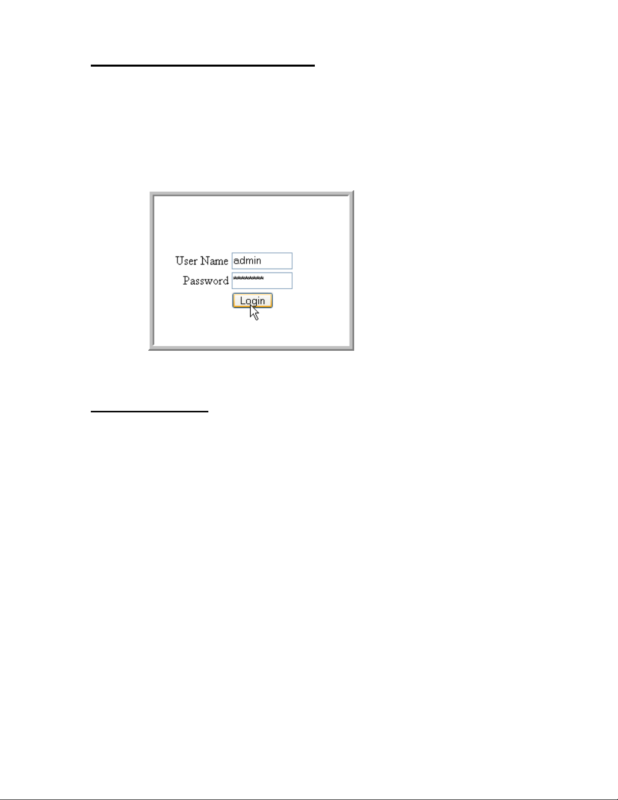
Follow these steps to start the switch Web interface:
1. Enter the IP address of the switch in the Web browser address field.
2. Enter the appropriate User Name and Password. The User Name and associated Password
Figure 1. Web Interface Panel-Example
are the same as those used for the terminal interface. Click on the Login button.
3. The System Description Menu displays as shown in Figure 2, with the navigation tree
appearing to the left of the screen.
4. Make a selection by clicking on the appropriate item in the navigation tree.
Web Page Layout
A Web interface panel for the switch Web page consists of three areas (Figure 2).
A banner graphic of the switch appears across the top of the panel.
The second area, a hierarchical-tree view appears to the left of the panel. The tree consists of a
combination of folders, subfolders, and configuration and status HTML pages. You can think
of the folders and subfolders as branches and the configuration and status HTML pages as
leaves. Only the selection of a leaf (not a folder or subfolder) will cause the display of a new
HTML page. A folder or subfolder has no corresponding HTML page.
The third area, at the bottom-right of the panel, displays the currently selected device
configuration status and/or the user configurable information that you have selected from the
tree view.
28 © 2001- 2011 D-Link Corporation. All Rights Reserved.
Page 29
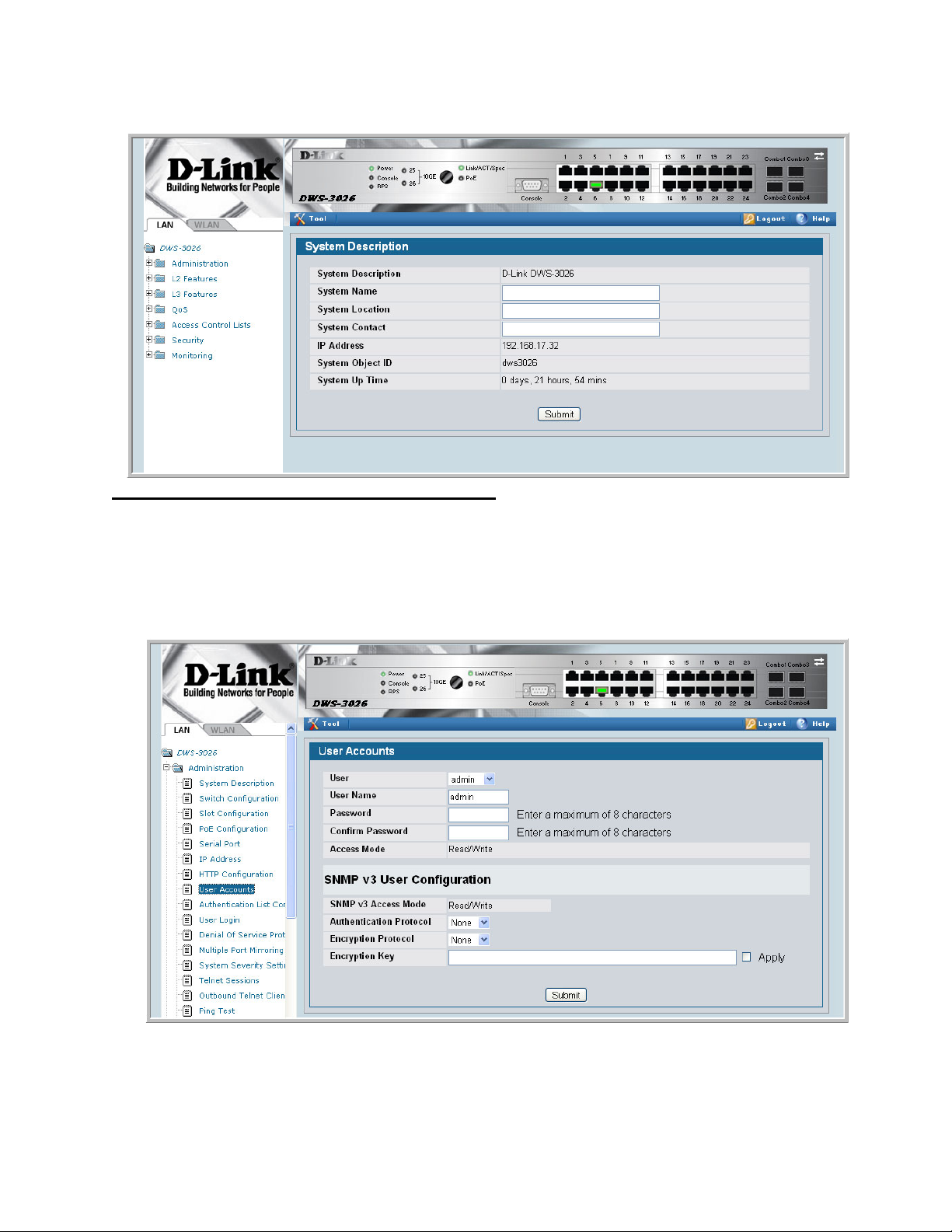
Figure 2. Web Interface Panel-Example
2 Using the Web Interface
Configuring an SNMP V3 User Profile
Configuring an SNMP V3 user profile is a part of user configuration. Any user can connect to
the switch using the SNMPv3 protocol, but for authentication and encryption, additional steps
are needed. Use the following steps to configure an SNMP V3 new user profile.
Figure 3. Configuring an SNMP V3 User Profile
1. From the LAN navigation menu, select LAN> Administration> User Accounts (see
Figure 3).
Starting the Web Interface 29
Page 30

Configuration Guide
2. Using the User pull-down menu, select Create to create a new user.
3. Enter a new user name in the User Name field.
4. Enter a new user password in the Password field and then retype it in the Confirm
NOTE: If SNMPv3 Authentication is to be implemented for this user, set a password
5. If you do not need authentication, go to Step 9.
6. To enable authentication, use the Authentication Protocol pull-down menu to select
7. If you do not need encryption, go to Step 9.
8. To enable encryption, use the Encryption Protocol pull-down menu to select DES for the
9. Click Submit.
Command Buttons
Password field.
of eight or more alphanumeric characters.
either MD5 or SHA for the authentication protocol.
encryption scheme. Then, enter an encryption code of eight or more alphanumeric
characters in the Encryption Key field.
The following command buttons are used throughout the Web interface panels for the switch:
Save Pressing the Save button implements and saves the changes you just made.
Some settings may require you to reset the system in order for them to take
effect.
Refresh Pressing the Refresh button that appears next to the Apply button in Web
interface panels refreshes the data on the panel.
Submit Pressing the Submit button sends the updated configuration to the switch.
Configuration changes take effect immediately, but these changes are not
retained across a power cycle unless a save is performed.
30 © 2001- 2011 D-Link Corporation. All Rights Reserved.
Page 31

Switching the Date/Time Zone
To configure the system date and time, from the Administration navigation menu, select
System Description (see Figure 4).
Figure 4. System Description Page
2 Using the Web Interface
Starting the Web Interface 31
Page 32

Configuration Guide
32 © 2001- 2011 D-Link Corporation. All Rights Reserved.
Page 33

Virtual LANs
Adding Virtual LAN (VLAN) support to a Layer 2 switch offers some of the benefits of both
bridging and routing. Like a bridge, a VLAN switch forwards traffic based on the Layer 2
header, which is fast. Like a router, it partitions the network into logical segments, which
provides better administration, security and management of multicast traffic.
A VLAN is a set of end stations and the switch ports that connect them. You can have many
reasons for the logical division, for example, department or project membership. The only
physical requirement is that the end station, and the port to which it is connected, both belong
to the same VLAN.
Each VLAN in a network has an associated VLAN ID, which appears in the IEEE 802.1Q tag
in the Layer 2 header of packets transmitted on a VLAN. An end station may omit the tag, or
the VLAN portion of the tag, in which case the first switch port to receive the packet may
either reject it or insert a tag using its default VLAN ID. A given port may handle traffic for
more than one VLAN, but it can only support one default VLAN ID.
3
Two features let you define packet filters that the switch uses as the matching criteria to
determine if a particular packet belongs to a particular VLAN.
• The IP-subnet Based VLAN feature lets you map IP addresses to VLANs by specifying a
source IP address, network mask, and the desired VLAN ID.
• The MAC-based VLAN feature let packets originating from end stations become part of a
VLAN according to source MAC address. To configure the feature, you specify a source
MAC address and a VLAN ID.
The Private Edge VLAN feature lets you set protection between ports located on the switch.
This means that a protected port cannot forward traffic to another protected port on the same
switch.
The feature does not provide protection between ports located on different switches.
The Voice VLAN feature lets you enable switch ports to carry traffic with defined settings so
that voice and data traffic are separated when coming onto the port.
33
Page 34

Configuration Guide
VLAN Configuration Example
The diagram in this section shows a switch with four ports configured to handle the traffic for
two VLANs. Port 0/2 handles traffic for both VLANs, while port 0/1 is a member of VLAN 2
only, and ports 0/3 and 0/4 are members of VLAN 3 only. The script following the diagram
shows the commands you would use to configure the switch as shown in the diagram.
Figure 5. VLAN Example Network Diagram
Layer 3 Switch
Port 0/1
VLAN 2
Port 0/2
VLANs 2 & 3
VLAN 2
Configuring a Guest VLAN
You can configure a Guest VLAN for clients to limit network access. If a client station fails to
authenticate using 802.1X or RADIUS, or if the client does not support 802.1X, then after the
authentication times out, the station is put on the guest VLAN configured for that switch port.
Port 0/4
VLAN 3
Port 0/3
VLAN 3
VLAN 3
For more information about how to configure a Guest VLAN for wired clients, see “Guest
VLAN” on page 107.
Configuring Dynamic VLAN Assignments
The software supports VLAN assignment for clients based on the RADIUS server
authentication. You need an external RADIUS server to use the dynamic VLAN assignment
feature. For information about how to configure the switch to allow dynamic VLAN
assignments, see “Configuring Dynamic VLAN Assignment” on page 109.
34 © 2001- 2011 D-Link Corporation. All Rights Reserved.
Page 35

CLI Examples
The following examples show how to create VLANs, assign ports to the VLANs, and assign a
VLAN as the default VLAN to a port.
Example #1: Create Two VLANs
Use the following commands to create two VLANs and to assign the VLAN IDs while leaving
the names blank.
(DWS-3024) #vlan database
(DWS-3024) (Vlan)#vlan 2
(DWS-3024) (Vlan)#vlan 3
(DWS-3024) (Vlan)#exit
Example #2: Assign Ports to VLAN2
This sequence shows how to assign ports to VLAN2, specify that frames will always be
transmitted tagged from all member ports, and that untagged frames will be rejected on
receipt.
3 Virtual LANs
(DWS-3024) #config
(DWS-3024) (Config)#interface 0/1
(DWS-3024) (Interface 0/1)#vlan participation include 2
(DWS-3024) (Interface 0/1)#vlan acceptframe vlanonly
(DWS-3024) (Interface 0/1)#exit
(DWS-3024) (Config)#interface 0/2
(DWS-3024) (Interface 0/2)#vlan participation include 2
(DWS-3024) (Interface 0/2)#vlan acceptframe vlanonly
(DWS-3024) (Interface 0/2)#exit
(DWS-3024) (Config)#exit
(DWS-3024) #config
(DWS-3024) (Config)#vlan port tagging all 2
(DWS-3024) (Config)#exit
Example #3: Assign Ports to VLAN3
This example shows how to assign the ports that will belong to VLAN 3, and to specify that
untagged frames will be accepted on port 0/4.
Note that port 0/2 belongs to both VLANs and that port 0/1 can never belong to VLAN 3.
(DWS-3024) #config
(DWS-3024) (Config)#interface 0/2
(DWS-3024) (Interface 0/2)#vlan participation include 3
(DWS-3024) (Interface 0/2)#exit
(DWS-3024) (Config)#interface 0/3
(DWS-3024) (Interface 0/3)#vlan participation include 3
(DWS-3024) (Interface 0/3)#exit
(DWS-3024) (Config)#interface 0/4
(DWS-3024) (Interface 0/4)#vlan participation include 3
(DWS-3024) (Interface 0/4)#exit
(DWS-3024) (Config)#
(DWS-3024) (Config)#exit
(DWS-3024) #config
(DWS-3024) (Config)#interface 0/4
(DWS-3024) (Interface 0/4)#vlan acceptframe all
CLI Examples 35
Page 36

Configuration Guide
(DWS-3024) (Interface 0/4)#exit
(DWS-3024) (Config)#exit
Example #4: Assign VLAN3 as the Default VLAN
This example shows how to assign VLAN 3 as the default VLAN for port 0/2.
(DWS-3024) #config
(DWS-3024) (Config)#interface 0/2
(DWS-3024) (Interface 0/2)#vlan pvid 3
(DWS-3024) (Interface 0/2)#exit
(DWS-3024) (Config)#exit
Example #5: Assign IP Addresses to VLAN 2
(DWS-3024) #vlan database
(DWS-3024) (Vlan)#vlan association subnet 192.168.10.10 255.255.255.0 2
(DWS-3024) (Vlan)#exit
(DWS-3024) #show vlan association subnet
IP Address IP Mask VLAN ID
---------------- ---------------- -------
192.168.10.10 255.255.255.0 2
(DWS-3024) #
Web Interface
You can perform the same configuration in the CLI Examples section by using the Web
interface. To create VLANs and specify port participation, use the LAN> L2 Features >
VLAN> VLAN Configuration page.
Figure 6. VLAN Configuration
36 © 2001- 2011 D-Link Corporation. All Rights Reserved.
Page 37

3 Virtual LANs
To specify the handling of untagged frames on receipt use the LAN> L2 Features > VLAN >
Port Configuration page.
Figure 7. VLAN Port Configuration
Private Edge VLANs
Use the Private Edge VLAN feature to prevent ports on the switch from forwarding traffic to
each other even if they are on the same VLAN.
• Protected ports cannot forward traffic to other protected ports in the same group, even if
they have the same VLAN membership. Protected ports can forward traffic to unprotected
ports.
• Unprotected ports can forward traffic to both protected and unprotected ports.
You can also configure groups of protected ports. Each group’s configuration consists of a
name and a mask of ports. A port can belong to only one set of protected ports. An unprotected
port can be added to a group as a protected port.
The group name is configurable by the network administrator.
Use the switchport protected command to designate a port as protected. Use the show
switchport protected command to display a listing of the protected ports.
Private Edge VLANs 37
Page 38

Configuration Guide
CLI Example
Example #1: switchport protected
(DWS-3024) #config
(DWS-3024) (Config)#interface 0/1
(DWS-3024) (Interface 0/1)#switchport protected ?
<cr> Press Enter to execute the command.
(DWS-3024) (Interface 0/1)#switchport protected
Example #2: show switchport protected
(DWS-3024) #show switchport protected
0/1
Voice VLAN
The voice VLAN feature enables switch ports to carry voice traffic with defined settings so
that voice and data traffic are separated when coming onto the port. A voice VLAN ensures
that the sound quality of an IP phone is safeguarded from deterioration when data traffic on the
port is high.
The inherent isolation provided by VLANs ensures that inter-VLAN traffic is under
management control and that network-attached clients cannot initiate a direct attack on voice
components. A QoS protocol based on the IEEE 802.1P class-of-service (CoS) protocol uses
classification and scheduling to send network traffic from the switch in a predictable manner.
The system uses the source MAC of the traffic traveling through the port to identify the IP
phone data flow.
Voice VLAN is enabled per-port basis. A port can participate only in one voice VLAN at a
time. The Voice VLAN feature is disabled by default.
To display the Voice VLAN Configuration page, click L2 Features > VLAN > Voice VLAN
Configuration.
38 © 2001- 2011 D-Link Corporation. All Rights Reserved.
Page 39

Figure 8. Voice VLAN Configuration
3 Virtual LANs
The Voice VLAN Configuration page contains the following fields:
• Voice VLAN Admin Mode — Click Enable or Disable to administratively turn the Voice
VLAN feature on or off for all ports.
• Unit/Slot/Port — Specifies Select the stack unit, slot, and port to configure this service on.
• Voice VLAN Interface Mode — Select one of the following interface modes:
- Disable: The voice VLAN service is disabled on this interface. Note that the Admin
mode field takes precedence; i.e., if a particular interface is enabled, but the Admin
Mode field is set to Disabled, then the service will not be operational.
- None: The voice VLAN service is disabled on this interface; however, unlike Disable
mode, the CoS override feature is still operational on the port.
- VLAN ID: The voice VLAN packets are uniquely identified by a number you assign.
All voice traffic carries this VLAN ID to distinguish it from other data traffic which is
assigned the port’s default VLAN ID. However, voice traffic is not prioritized differently than other traffic.
- dot1p: This parameter is set by the VoIP device for all voice traffic to distinguish
voice data from other traffic. All other traffic is assigned the port’s default VLAN ID.
This feature may not be supported by all hardware configurations.
- Untagged: Configures the phone to send untagged voice traffic.
• CoS Override Mode — Overrides the 802.1p class-of-service (CoS) value for all data
(non-voice) packets arriving at the port. Thus any rogue client that is also connected to the
voice VLAN port cannot deteriorate the voice traffic.
• Operational State — Indicates whether the voice VLAN is operational.
If you make any changes, click Submit to apply the change to the system.
Click Refresh to display the latest information from the router.
Voice VLAN 39
Page 40

Configuration Guide
40 © 2001- 2011 D-Link Corporation. All Rights Reserved.
Page 41

Storm Control
A traffic storm is a condition that occurs when incoming packets flood the LAN, which creates
performance degradation in the network. The Unified Switch’s Storm Control feature protects
against this condition.
The Unified Switch provides broadcast, multicast, and unicast storm recovery for individual
interfaces or for all interfaces.
Unicast Storm Control protects against traffic whose MAC addresses are not known by the
system.
For broadcast, multicast, and unicast storm control, if the rate of traffic ingressing on an
interface increases beyond the configured threshold for that type, the traffic is dropped.
4
To configure storm control, you’ll enable the feature for all interfaces or for individual
interfaces, and you’ll set the threshold (storm control level) beyond which the broadcast,
multicast, or unicast traffic will be dropped.
Configuring a storm-control level also enables that form of storm-control. Disabling a stormcontrol level (using the “no” version of the command) sets the storm-control level back to
default value and disables that form of storm-control. Using the “no” version of the “stormcontrol” command (not stating a “level”) disables that form of storm-control but maintains the
configured “level” (to be active next time that form of storm-control is enabled).
CLI Example
Example #1: Set Broadcast Storm Control for All Interfaces
(DWS-3024) #config
(DWS-3024) (Config)#storm-control broadcast ?
all Configure storm-control features for all ports.
(DWS-3024) (Config)#storm-control broadcast all ?
<cr> Press Enter to execute the command.
level Configure storm-control thresholds.
(DWS-3024) (Config)#storm-control broadcast all level ?
CLI Example 41
Page 42

Configuration Guide
<rate> Enter the storm-control threshold as percent of port
speed.
(DWS-3024) (Config)#storm-control broadcast all level 7
(DWS-3024) (Config)#exit
(DWS-3024)
Example #2: Set Multicast Storm Control for All Interfaces
(DWS-3024) #config
(DWS-3024) (Config)#storm-control multicast all ?
<cr> Press Enter to execute the command.
level Configure storm-control thresholds.
(DWS-3024) (Config)#storm-control multicast all level 8
(DWS-3024) (Config)#exit
(DWS-3024) #
Example #3: Set Unicast Storm Control for All Interfaces
(DWS-3024) #config
(DWS-3024) (Config)#storm-control unicast all level 5
(DWS-3024) (Config)#exit
(DWS-3024) #
42 © 2001- 2011 D-Link Corporation. All Rights Reserved.
Page 43

Web Interface
The Storm Control configuration options are available on the Port Configuration Web page
under the Administration folder.
Figure 9. Port Configuration (Storm Control)
4 Storm Control
Web Interface 43
Page 44

Configuration Guide
44 © 2001- 2011 D-Link Corporation. All Rights Reserved.
Page 45

Trunking (Link Aggregation)
This section shows how to use the Trunking feature (also known as Link Aggregation) to
configure port-channels by using the CLI and the Web interface.
The Link Aggregation (LAG) feature allows the switch to treat multiple physical links
between two end-points as a single logical link called a port-channel. All of the physical links
in a given port-channel must operate in full-duplex mode at the same speed.
You can use the feature to directly connect two switches when the traffic between them
requires high bandwidth and reliability, or to provide a higher bandwidth connection to a
public network.
You can configure the port-channels as either dynamic or static. Dynamic configuration uses
the IEEE 802.3ad standard, which provides for the periodic exchanges of LACPDUs. Static
configuration is used when connecting the switch to an external switch that does not support
the exchange of LACPDUs.
5
The feature offers the following benefits:
• Increased reliability and availability — if one of the physical links in the port-channel
goes down, traffic is dynamically and transparently reassigned to one of the other physical
links.
• Increased bandwidth — the aggregated physical links deliver higher bandwidth than each
individual link.
• Incremental increase in bandwidth — A physical upgrade could produce a 10-times
increase in bandwidth; LAG produces a two- or five-times increase, useful if only a small
increase is needed.
Management functions treat a port-channel as if it were a single physical port.
You can include a port-channel in a VLAN. You can configure more than one port-channel for
a given switch.
CLI Example
The following shows an example of configuring the Unified Switch to support Link
Aggregation (LAG) to a server and to a Layer 2 switch.
CLI Example 45
Page 46

Configuration Guide
Figure 10 shows the example network.
Figure 10. LAG/Port-channel Example Network Diagram
Server
Port 0/2
LAG_10
Port 0/8
LAG_20
Subnet
3
Port 0/3
LAG_10
Layer 3 Switch
Port 0/9
LAG_20
Layer 2 Switch
Example 1: Create two port-channels:
(DWS-3024) #config
(DWS-3024) (Config)#port-channel lag_10
(DWS-3024) (Config)#port-channel lag_20
(DWS-3024) (Config)#exit
Use the show port-channel all command to show the logical interface ids you will use to
identify the port-channels in subsequent commands. Assume that lag_10 is assigned id 3/1 and
lag_20 is assigned id 3/2.
46 © 2001- 2011 D-Link Corporation. All Rights Reserved.
Subnet 3Subnet 2
Page 47

5 Trunking (Link Aggregation)
(DWS-3024) #show port-channel all
Port- Link
Log. Channel Adm. Trap STP Mbr Port Port
Intf Name Link Mode Mode Mode Type Ports Speed Active
------ ------------- ----- ---- ---- ------ ------- ------ --------- -----3/1 lag_10 Down En. En. Dis. Dynamic
3/2 lag_20 Down En. En. Dis. Dynamic
Example 2: Add the physical ports to the port-channels:
(DWS-3024) #config
(DWS-3024) (Config)#interface 0/2
(DWS-3024) (Interface 0/2)#addport 3/1
(DWS-3024) (Interface 0/2)#exit
(DWS-3024) (Config)#interface 0/3
(DWS-3024) (Interface 0/3)#addport 3/1
(DWS-3024) (Interface 0/3)#exit
(DWS-3024) (Config)#exit
(DWS-3024) #config
(DWS-3024) (Config)#interface 0/8
(DWS-3024) (Interface 0/8)#addport 3/2
(DWS-3024) (Interface 0/8)#exit
(DWS-3024) (Config)#interface 0/9
(DWS-3024) (Interface 0/9)#addport 3/2
(DWS-3024) (Interface 0/9)#exit
(DWS-3024) (Config)#exit
Example 3: Enable both port-channels:
By default, the system enables link trap notification
(DWS-3024) #config
(DWS-3024) (Config)#port-channel adminmode all
(DWS-3024) (Config)#exit
At this point, the LAGs could be added to the default management VLAN.
CLI Example 47
Page 48

Configuration Guide
Web Interface Configuration — LAGs/Port-channels
To perform the same configuration using the Web interface, use the LAN> L2 Features >
Trunking > Configuration page.
Figure 11. Trunking Configuration
To create the port-channels, specify port participation and enable Link Aggregation (LAG)
support on the switch.
48 © 2001- 2011 D-Link Corporation. All Rights Reserved.
Page 49

IGMP Snooping
This section describes the Internet Group Management Protocol (IGMP) feature: IGMPv3 and
IGMP Snooping. The IGMP Snooping feature enables the switch to monitor IGMP
transactions between hosts and routers. It can help conserve bandwidth by allowing the switch
to forward IP multicast traffic only to connected hosts that request multicast traffic.
Overview
IGMP:
• Uses Version 3 of IGMP
• Includes snooping
• Snooping can be enabled per VLAN
6
CLI Examples
The following are examples of the commands used in the IGMP Snooping feature.
Example #1: show igmpsnooping
(DWS-3024) #show igmpsnooping ?
<cr> Press Enter to execute the command.
<slot/port> Enter interface in slot/port format.
mrouter Display IGMP Snooping Multicast Router information.
<1-3965> Display IGMP Snooping valid VLAN ID information.
(DWS-3024) #show igmpsnooping
Admin Mode...............................Enable
Multicast Control Frame Count............0
Interfaces Enabled for IGMP Snooping.....0/10
Vlans enabled for IGMP snooping..........20
Overview 49
Page 50

Configuration Guide
Example #2: show mac-address-table igmpsnooping
(DWS-3024) #show mac-address-table igmpsnooping ?
<cr> Press Enter to execute the command.
(DWS-3024) #show mac-address-table igmpsnooping
MAC Address Type Description Interfaces
----------------------- ------- ------------ -----------
00:01:01:00:5E:00:01:16 Dynamic Network Assist Fwd: 0/47
00:01:01:00:5E:00:01:18 Dynamic Network Assist Fwd: 0/47
00:01:01:00:5E:37:96:D0 Dynamic Network Assist Fwd: 0/47
00:01:01:00:5E:7F:FF:FA Dynamic Network Assist Fwd: 0/47
00:01:01:00:5E:7F:FF:FE Dynamic Network Assist Fwd: 0/47
Example #3: set igmp (Global Config Mode)
(DWS-3026) (Config)#set igmp ?
<cr> Press enter to execute the command.
groupmembership-interval Configure IGMP Group Membership Interval
(secs).
interfacemode Enable/Disable IGMP Snooping.
maxresponse Configure IGMP Max Response time (secs).
mcrtrexpiretime Sets the Multicast Router Present Expiration
time on the system.
(DWS-3026) (Config)#set igmp
Example #4: set igmp (Interface Config Mode)
(DWS-3026) (Config)#interface 0/2
(DWS-3026) (Interface 0/2)#set igmp ?
<cr> Press enter to execute the command.
fast-leave Enable/Disable Fast-Leave on a selected
interface
groupmembership-interval Configure IGMP Group Membership Interval
(secs).
maxresponse Configure IGMP Max Response time (secs).
mcrtrexpiretime Sets the Multicast Router Present Expiration
time on
the system.
mrouter Configure Multicast Router port.
(DWS-3026) (Interface 0/2)#set igmp
50 © 2001- 2011 D-Link Corporation. All Rights Reserved.
Page 51

Web Examples
The following web pages are used in the IGMP Snooping feature. Click Help for more
information on the web interface.
Figure 12. IGMP Snooping - Global Configuration and Status Page
6 IGMP Snooping
Web Examples 51
Page 52

Configuration Guide
Figure 13. IGMP Snooping - Interface Configuration Page
Figure 14. IGMP Snooping VLAN Configuration
52 © 2001- 2011 D-Link Corporation. All Rights Reserved.
Page 53

Figure 15. IGMP Snooping - VLAN Status Page
6 IGMP Snooping
Figure 16. IGMP Snooping - Multicast Router Statistics Page
Web Examples 53
Page 54

Configuration Guide
Figure 17. IGMP Snooping - Multicast Router Configuration Page
Figure 18. IGMP Snooping - Multicast Router VLAN Statistics Page
54 © 2001- 2011 D-Link Corporation. All Rights Reserved.
Page 55

Figure 19. IGMP Snooping - Multicast Router VLAN Configuration Page
6 IGMP Snooping
Web Examples 55
Page 56

Configuration Guide
56 © 2001- 2011 D-Link Corporation. All Rights Reserved.
Page 57

Port Mirroring
This section describes the Port Mirroring feature, which can serve as a diagnostic tool,
debugging tool, or means of fending off attacks.
Overview
Port mirroring selects network traffic from specific ports for analysis by a network analyzer,
while allowing the same traffic to be switched to its destination. You can configure many
switch ports as source ports and one switch port as a destination port. You can also configure
how traffic is mirrored on a source port. Packets received on the source port, transmitted on a
port, or both received and transmitted, can be mirrored to the destination port.
7
CLI Examples
The following are examples of the commands used in the Port Mirroring feature.
Example #1: Set up a Port Mirroring Session
The following command sequence enables port mirroring and specifies a source and
destination ports.
(DWS-3024) #config
(DWS-3024) (Config)#monitor session 1 mode
(DWS-3024) (Config)#monitor session 1 source interface 0/7 ?
<cr> Press Enter to execute the command.
rx Monitor ingress packets only.
tx Monitor egress packets only.
(DWS-3024) (Config)#monitor session 1 source interface 0/7
(DWS-3024) (Config)#monitor session 1 destination interface 0/8
(DWS-3024) (Config)#exit
Overview 57
Page 58

Configuration Guide
Example #2: Show the Port Mirroring Session
(DWS-3024) #show monitor session 1
Session ID Admin Mode Probe Port Mirrored Port Type
---------- ---------- ---------- ------------- ----1 Enable 0/8 0/7 Rx,Tx
(DWS-3024) #Monitor session ID “1” - “1” is a hardware limitation.
Example #3: Show the Status of All Ports
(DWS-3024) #show port all
Intf Type Mode Mode Status Status Trap Mode
---- ---- ------ -------- -------- ------ ---- ---0/1 Enable Auto Up Enable Enable
0/2 Enable Auto Down Enable Enable
0/3 Enable Auto Down Enable Enable
0/4 Enable Auto Down Enable Enable
0/5 Enable Auto Down Enable Enable
0/6 Enable Auto Down Enable Enable
0/7 Mirror Enable Auto Down Enable Enable
0/8 Probe Enable Auto Down Enable Enable
0/9 Enable Auto Down Enable Enable
0/10 Enable Auto Down Enable Enable
Admin Physical Physical Link Link LACP
Example #4: Show the Status of the Source and Destination Ports
Use this command for a specific port. The output shows whether the port is the mirror or the
probe port, what is enabled or disabled on the port, etc.
(DWS-3024) #show port 0/7
Intf Type Mode Mode Status Status Trap Mode
---- ---- ------ -------- -------- ------ ---- ---0/7 Mirror Enable Auto Down Enable Enable
(DWS-3024) #show port 0/8
Intf Type Mode Mode Status Status Trap Mode
---- ---- ------ -------- -------- ------ ---- ---0/8 Probe Enable Auto Down Enable Enable
Admin Physical Physical Link Link LACP
Admin Physical Physical Link Link LACP
58 © 2001- 2011 D-Link Corporation. All Rights Reserved.
Page 59

Web Examples
The following web pages are used with the Port Mirroring feature.
Figure 20. Multiple Port Mirroring
7 Port Mirroring
Figure 21. Multiple Port Mirroring - Add Source Ports
Web Examples 59
Page 60

Configuration Guide
Figure 22. System - Port Utilization Summary
60 © 2001- 2011 D-Link Corporation. All Rights Reserved.
Page 61

Link Layer Discovery Protocol
The Link Layer Discovery Protocol (LLDP) feature allows individual interfaces on the switch
to advertise major capabilities and physical descriptions. Network managers can view this
information and identify system topology and detect bad configurations on the LAN.
LLDP has separately configurable transmit and receive functions. Interfaces can transmit and
receive LLDP information.
CLI Examples
Example #1: Set Global LLDP Parameters
8
Use the following sequence to specify switch-wide notification interval and timers for all
LLDP interfaces.
(DWS-3024) #config
(DWS-3024) (Config)#lldp ?
notification-interval Configure minimum interval to send remote data
change notifications
timers Configure the LLDP global timer values.
(DWS-3024) (Config)#lldp notification-interval ?
<interval-seconds> Range <5 - 3600> seconds.
(DWS-3024) (Config)#lldp notification-interval 1000
(DWS-3024) (Config)#lldp timers ?
<cr> Press Enter to execute the command.
hold The interval multiplier to set local LLDP data TTL.
interval The interval in seconds to transmit local LLDP data.
reinit The delay before re-initialization.
(DWS-3024) (Config)#lldp timers hold 8 reinit 5
(DWS-3024) (Config)#exit
CLI Examples 61
Page 62

Configuration Guide
(DWS-3024) #
Example #2: Set Interface LLDP Parameters
The following commands configure interface 0/10 to transmit and receive LLDP information.
(DWS-3024) #config
(DWS-3024) (Config)#interface 0/10
(DWS-3024) (Interface 0/10)#lldp ?
notification Enable/Disable LLDP remote data change notifications.
receive Enable/Disable LLDP receive capability.
transmit Enable/Disable LLDP transmit capability.
transmit-mgmt Include/Exclude LLDP management address TLV.
transmit-tlv Include/Exclude LLDP optional TLV(s).
(DWS-3024) (Interface 0/10)#lldp receive
(DWS-3024) (Interface 0/10)#lldp transmit
(DWS-3024) (Interface 0/10)#lldp transmit-mgmt
(DWS-3024) (Interface 0/10)#exit
(DWS-3024) (Config)#exit
(DWS-3024) #
Example #3: Show Global LLDP Parameters
(DWS-3024) #show lldp
LLDP Global Configuration
Transmit Interval............................ 30 seconds
Transmit Hold Multiplier..................... 8
Reinit Delay................................. 5 seconds
Notification Interval........................ 1000 seconds
(DWS-3024) #
Example #4 Show Interface LLDP Parameters
(DWS-3024) #show lldp interface 0/10
LLDP Interface Configuration
Interface Link Transmit Receive Notify TLVs Mgmt
--------- ------ -------- -------- -------- ------- ---0/10 Down Enabled Enabled Disabled Y
TLV Codes: 0- Port Description, 1- System Name
2- System Description, 3- System Capabilities
(DWS-3024) #
62 © 2001- 2011 D-Link Corporation. All Rights Reserved.
Page 63

8 Link Layer Discovery Protocol
Using the Web Interface to Configure LLDP
The LLDP menu page contains links to the following features:
• LLDP Configuration
• LLDP Statistics
• LLDP Connections
• LLDP Configuration
Use the LLDP Global Configuration page to specify LLDP parameters.
Figure 23. LLDP Global Configuration
The LLDP Global Configuration page contains the following fields:
• Transmit Interval (1-32768) — Specifies the interval at which frames are transmitted.
The default is 30 seconds.
• Hold Multiplier (2-10) — Specifies multiplier on the transmit interval to assign to TTL.
Default is 4.
• Re-Initialization Delay (1-10) — Specifies delay before a re-initialization. Default is 2 sec-
onds.
• Notification Interval (5-3600) — Limits the transmission of notifications. The default is
5 seconds.
Using the Web Interface to Configure LLDP 63
Page 64

Configuration Guide
Use the LLDP Interface Configuration screen to specify transmit and receive functions for
individual interfaces.
Figure 24. LLDP Interface Configuration
Interface Parameters
• Interface — Specifies the port to be affected by these parameters.
• Tr a ns m it Mode — Enables or disables the transmit function. The default is disabled.
• Receive Mode — Enables or disables the receive function. The default is disabled.
• Transmit Management Information — Enables or disables transmission of management
address instance. Default is disabled.
• Notification Mode — Enables or disables remote change notifications. The default is dis-
abled.
• Included TLVs — Selects TLV information to transmit. Choices include System Name,
System Capabilities, System Description, and Port Description.
64 © 2001- 2011 D-Link Corporation. All Rights Reserved.
Page 65

Figure 25. LLDP Interface Summary
8 Link Layer Discovery Protocol
Figure 26. LLDP Statistics
You can also use the pages in the LAN> Monitoring > LLDP Status folder to view
information about local and remote devices.
Using the Web Interface to Configure LLDP 65
Page 66

Configuration Guide
66 © 2001- 2011 D-Link Corporation. All Rights Reserved.
Page 67

Denial of Service Attack Protection
This section describes the D-Link DWS-3000 switch’s Denial of Service Protection feature.
Overview
Denial of Service:
• Spans two categories:
- Protection of the Unified Switch
- Protection of the network
• Protects against the exploitation of a number of vulnerabilities which would make the host
or network unstable
• Compliant with Nessus. Nessus is a widely-used vulnerability assessment tool.
• The Unified Switch provides a number of features that help a network administrator pro-
tect networks against DoS attacks.
9
CLI Examples
Enter from Global Config mode:
(DWS-3024) #configure
(DWS-3024) (Config)#dos-control sipdip
(DWS-3024) (Config)#dos-control firstfrag
(DWS-3024) (Config)#dos-control tcpfrag
(DWS-3024) (Config)#dos-control l4port
(DWS-3024) (Config)#dos-control icmp
(DWS-3024) (Config)#exit
(DWS-3024) #show dos-control
SIPDIP Mode.................................... Enable
Overview 67
Page 68

Configuration Guide
First Fragment Mode............................ Enable
Min TCP Hdr Size............................... 20
TCP Fragment Mode.............................. Enable
TCP Flag Mode.................................. Disable
L4 Port Mode................................... Enable
ICMP Mode...................................... Enable
Max ICMP Pkt Size.............................. 512
Web Interface
You can configure the Denial of Service feature from the Denial of Service Protection
Configuration page.
Figure 27. Denial of Service Protection Configuration
68 © 2001- 2011 D-Link Corporation. All Rights Reserved.
Page 69

Port Routing
The first networks were small enough for the end stations to communicate directly. As
networks grew, Layer 2 bridging was used to segregate traffic, a technology that worked well
for unicast traffic, but had problems coping with large quantities of multicast packets. The next
major development was routing, where packets were examined and redirected at Layer 3. End
stations needed to know how to reach their nearest router, and the routers had to understand
the network topology so that they could forward traffic. Although bridges tended to be faster
than routers, using routers allowed the network to be partitioned into logical subnetworks,
which restricted multicast traffic and also facilitated the development of security mechanisms.
An end station specifies the destination station’s Layer 3 address in the packet’s IP header but
sends the packet to the MAC address of a router. When the Layer 3 router receives the packet,
at a minimum it does the following:
10
• Looks up the Layer 3 address in its address table to determine the outbound port
• Updates the Layer 3 header
• Recreates the Layer 2 header
The router’s IP address is often statically configured in the end station, although the Unified
Switch supports DHCP that allow the address to be assigned dynamically. You may assign
static entries in the routing tables used by the router.
Port Routing Configuration
The Unified Switch always supports Layer 2 bridging, but Layer 3 routing must be explicitly
enabled, first for the Unified Switch as a whole, and then for each port which is to participate
in the routed network.
The configuration commands used in this section’s example enable IP routing on ports 0/2, 0/
3, and 0/5. The router ID is set to the Unified Switch’s management IP address, or to that of
any active router interface if the management address is not configured.
After you’ve issued the routing configuration commands, the following functions are active:
• IP Forwarding - responsible for forwarding received IP packets.
• ARP Mapping - responsible for maintaining the ARP Table used to correlate IP and MAC
addresses. The table contains both static entries and entries dynamically updated based on
information in received ARP frames.
Port Routing Configuration 69
Page 70

Configuration Guide
• Routing Table Object - responsible for maintaining the routing table populated by local
CLI Examples
The diagram in this section shows a Unified Switch configured for port routing. It connects
three different subnets, each connected to a different port. The script shows the commands you
would use to configure a Unified Switch to provide the port routing support shown in the
diagram.
Figure 28. Port Routing Example Network Diagram
and static routes.
Subnet 3
Port 0/3
192.130.3.1
Unified Switch
acting as a router
Port 0/2
192.150.2.2
Subnet 2
Port 0/5
192.64.4.1
Example 1. Enabling Routing for the Switch
Use the following command to enable routing for the switch. Execution of the command
enables IP forwarding by default.
config
ip routing
exit
Subnet 5
Example 2. Enabling Routing for Ports on the Switch
Use the following commands to enable routing for ports on the switch. The default link-level
encapsulation format is Ethernet. Configure the IP addresses and subnet masks for the ports.
70 © 2001- 2011 D-Link Corporation. All Rights Reserved.
Page 71

10 Port Routing
Network directed broadcast frames are dropped and the maximum transmission unit (MTU)
size is 1500 bytes.
config
interface 0/2
routing
ip address 192.150.2.2 255.255.255.0
exit
exit
config
interface 0/3
routing
ip address 192.130.3.1 255.255.255.0
exit
exit
config
interface 0/5
routing
ip address 192.64.4.1 255.255.255.0
exit
exit
CLI Examples 71
Page 72

Configuration Guide
Using the Web Interface to Configure Routing
Use the following screens to perform the same configuration using the Graphical User
Interface:
To enable routing for the switch, as shown in Example 1. Enabling Routing for the Switch, use
the LAN> L3 Features> IP > Configuration page.
Figure 29. IP Configuration
To configure routing on each interface, as shown in Example 2. Enabling Routing for Ports on
the Switch, use the LAN> L3 Features > IP > Interface Configuration page.
Figure 30. IP Interface Configuration
72 © 2001- 2011 D-Link Corporation. All Rights Reserved.
Page 73

VLAN Routing
You can configure the Unified Switch with some ports supporting VLANs and some
supporting routing. You can also configure the Unified Switch to allow traffic on a VLAN to
be treated as if the VLAN were a router port.
When a port is enabled for bridging (default) rather than routing, all normal bridge processing
is performed for an inbound packet, which is then associated with a VLAN. Its MAC
Destination Address (MAC DA) and VLAN ID are used to search the MAC address table. If
routing is enabled for the VLAN and the MAC DA of an inbound unicast packet is that of the
internal bridge-router interface, the packet will be routed. An inbound multicast packet will be
forwarded to all ports in the VLAN, plus the internal bridge-router interface if it was received
on a routed VLAN.
Since a port can be configured to belong to more than one VLAN, VLAN routing might be
enabled for all of the VLANs on the port, or for a subset. VLAN Routing can be used to allow
more than one physical port to reside on the same subnet. It could also be used when a VLAN
spans multiple physical networks, or when additional segmentation or security is required.
11
This section shows how to configure the Unified Switch to support VLAN routing. A port can
be either a VLAN port or a router port, but not both. However, a VLAN port may be part of a
VLAN that is itself a router port.
VLAN Routing Configuration
This section provides an example of how to configure the Unified Switch to support VLAN
routing. The configuration of the VLAN router port is similar to that of a physical port. The
main difference is that, after the VLAN has been created, you must use the show ip vlan
command to determine the VLAN’s interface ID so that you can use it in the router
configuration commands.
CLI Examples
The diagram in this section shows a Unified Switch configured for VLAN routing. It connects
two VLANs, with two ports participating in one VLAN, and one port in the other. The script
shows the commands you would use to configure the Unified Switch to provide the VLAN
routing support shown in the diagram.
VLAN Routing Configuration 73
Page 74

Configuration Guide
Figure 31. VLAN Routing Example Network Diagram
Layer 3 Switch
Physical Port 0/2
VLAN Router Port 4/1
192.150.3.1
Layer 2 Switch
VLAN 10
Physical
Port 0/1
Example 1: Create Two VLANs
The following commands show an example of how to create two VLANs with egress frame
tagging enabled.
vlan database
vlan 10
vlan 20
exit
Physical Port 0/3
VLAN Router Port 4/2
192.150.4.1
Layer 2 Switch
VLAN 20
config
interface 0/1
vlan participation include 10
exit
interface 0/2
vlan participation include 10
exit
interface 0/3
vlan participation include 20
exit
exit
config
vlan port tagging all 10
vlan port tagging all 20
exit
74 © 2001- 2011 D-Link Corporation. All Rights Reserved.
Page 75

11 VLAN Routing
Next specify the VLAN ID assigned to untagged frames received on the ports.
config
interface 0/1
vlan pvid 10
exit
interface 0/2
vlan pvid 10
exit
interface 0/3
vlan pvid 20
exit
exit
Example 2: Set Up VLAN Routing for the VLANs and the Switch.
The following commands show how to enable routing for the VLANs:
vlan database
vlan routing 10
vlan routing 20
exit
show ip vlan
This returns the logical interface IDs that will be used in subsequent routing commands.
Assume that VLAN 10 is assigned ID 4/1 and VLAN 20 is assigned ID 4/2.
Enable routing for the switch:
config
ip routing
exit
The next sequence shows an example of configuring the IP addresses and subnet masks for the
VLAN router ports.
config
interface 4/1
ip address 192.150.3.1 255.255.255.0
exit
interface 4/2
ip address 192.150.4.1 255.255.255.0
exit
exit
CLI Examples 75
Page 76

Configuration Guide
Using the Web Interface to Configure VLAN Routing
You can perform the same configuration by using the Web Interface.
Use the LAN> L2 Features > VLAN> VLAN Configuration page to create the VLANs,
specify port participation, and configure whether frames will be transmitted tagged or
untagged.
Figure 32. VLAN Configuration
Use the LAN> L2 Features > VLAN > Port Configuration page to specify the handling of
untagged frames on receipt.
Figure 33. VLAN Port Configuration
76 © 2001- 2011 D-Link Corporation. All Rights Reserved.
Page 77

11 VLAN Routing
Use the LAN> L3 Features > VLAN Routing > Configuration page to enable VLAN
routing and configure the ports.
Figure 34. VLAN Routing Configuration
To enable routing for the switch, use the LAN> L3 Features > IP > Configuration page.
Figure 35. Enabling Routing
Using the Web Interface to Configure VLAN Routing 77
Page 78

Configuration Guide
Use the LAN> L3 Features > IP > Interface Configuration page to enable routing for the
ports and configure their IP addresses and subnet masks.
Figure 36. IP Interface Configuration
78 © 2001- 2011 D-Link Corporation. All Rights Reserved.
Page 79

Virtual Router Redundancy Protocol
When an end station is statically configured with the address of the router that will handle its
routed traffic, a single point of failure is introduced into the network. If the router goes down,
the end station is unable to communicate. Since static configuration is a convenient way to
assign router addresses, Virtual Router Redundancy Protocol (VRRP) was developed to
provide a backup mechanism.
VRRP eliminates the single point of failure associated with static default routes by enabling a
backup router to take over from a “master” router without affecting the end stations using the
route. The end stations will use a “virtual” IP address that will be recognized by the backup
router if the master router fails. Participating routers use an election protocol to determine
which router is the master router at any given time. A given port may appear as more than one
virtual router to the network, also, more than one port on a Unified Switch may be configured
as a virtual router. Either a physical port or a routed VLAN may participate.
12
CLI Examples
This example shows how to configure the Unified Switch to support VRRP. Router 1 will be
the default master router for the virtual route, and Router 2 will be the backup router.
CLI Examples 79
Page 80

Configuration Guide
Figure 37. VRRP Example Network Configuration
Port 0/2
192.150.2.1
Virtual Router ID 20
Virtual Addr. 192.150.2.1
Layer 3 Switch acting
as Router 1
Layer 3 Switch acting
as Router 2
Port 0/4
192.150.4.1
Virtual Router ID 20
Virtual Addr. 192.150.2.1
Layer 2 Switch
Hosts
Example 1: Configuring VRRP on the Switch as a Master Router
Enable routing for the switch. IP forwarding is then enabled by default.
config
ip routing
exit
Configure the IP addresses and subnet masks for the port that will participate in the protocol.
config
interface 0/2
routing
ip address 192.150.2.1 255.255.255.0
exit
Enable VRRP for the switch.
config
ip vrrp
exit
Assign virtual router IDs to the port that will participate in the protocol.
config
interface 0/2
ip vrrp 20
80 © 2001- 2011 D-Link Corporation. All Rights Reserved.
Page 81

12 Virtual Router Redundancy Protocol
Specify the IP address that the virtual router function will recognize. Note that the virtual IP
address on port 0/2 is the same as the port’s actual IP address, therefore this router will always
be the VRRP master when it is active. And the priority default is 255.
ip vrrp 20 ip 192.150.2.1
Enable VRRP on the port.
ip vrrp 20 mode
exit
Example 2: Configuring VRRP on the Switch as a Backup Router
Enable routing for the switch. IP forwarding is then enabled by default.
config
ip routing
exit
Configure the IP addresses and subnet masks for the port that will participate in the protocol.
config
interface 0/4
routing
ip address 192.150.4.1 255.255.255.0
exit
Enable VRRP for the switch.
config
ip vrrp 20
exit
Assign virtual router IDs to the port that will participate in the protocol.
config
interface 0/4
ip vrrp 20
Specify the IP address that the virtual router function will recognize. Since the virtual IP
address on port 0/4 is the same as Router 1’s port 0/2 actual IP address, this router will always
be the VRRP backup when Router 1 is active.
ip vrrp 20 ip 192.150.2.1
Set the priority for the port. The default priority is 100.
ip vrrp 20 priority 254
Enable VRRP on the port.
ip vrrp 20 mode
exit
CLI Examples 81
Page 82

Configuration Guide
Using the Web Interface to Configure VRRP
Use the following screens to perform the same configuration using the Graphical User
Interface:
To enable routing for the switch, use the LAN > L3 Features > IP > Configuration page.
Figure 38. IP Configuration
To enable routing for the ports and configure their IP addresses and subnet masks, use the
LAN> L3 Features > IP > Interface Configuration page.
Figure 39. IP Interface Configuration
82 © 2001- 2011 D-Link Corporation. All Rights Reserved.
Page 83

12 Virtual Router Redundancy Protocol
To enable VRRP for the switch, use the LAN> L3 Features > VRRP > VRRP
Configuration page.
Figure 40. VRRP Configuration
To configure virtual router settings, use the LAN> L3 Features > VRRP > Virtual Router
Configuration page.
Figure 41. Virtual Router Configuration
Using the Web Interface to Configure VRRP 83
Page 84

Configuration Guide
84 © 2001- 2011 D-Link Corporation. All Rights Reserved.
Page 85

Proxy Address Resolution Protocol (ARP)
This section describes the Proxy Address Resolution Protocol (ARP) feature.
Overview
• Proxy ARP allows a router to answer ARP requests where the target IP address is not the
router itself but a destination that the router can reach.
• If a host does not know the default gateway, proxy ARP can learn the first hop.
• Machines in one physical network appear to be part of another logical network.
• Without proxy ARP, a router responds to an ARP request only if the target IP address is an
address configured on the interface where the ARP request arrived.
13
CLI Examples
The following are examples of the commands used in the proxy ARP feature.
Example #1 show ip interface
(DWS-3024) #show ip interface ?
<slot/port> Enter an interface in slot/port format.
brief Display summary information about IP configuration
settings for all ports.
loopback Display the configured Loopback interface information.
(DWS-3024) #show ip interface 0/24
Routing Mode................................... Disable
Administrative Mode............................ Enable
Forward Net Directed Broadcasts................ Disable
Proxy ARP...................................... Enable
Active State................................... Inactive
Link Speed Data Rate........................... Inactive
MAC Address.................................... 00:10:18:82:06:5F
Encapsulation Type............................. Ethernet
IP MTU......................................... 1500
Overview 85
Page 86

Example #2: ip proxy-arp
DWS-3024) (Interface 0/24)#ip proxy-arp ?
<cr> Press Enter to execute the command.
(DWS-3024) (Interface 0/24)#ip proxy-arp
Web Example
The following web pages are used in the proxy ARP feature.
Figure 42. Proxy ARP Configuration
Web Example 86
Page 87

Routing Information Protocol (RIP)
This section describes the Routing Information Protocol (RIP). RIP is an Interior Gateway
Protocol (IGP) based on the Bellman-Ford algorithm and targeted at smaller networks
(network diameter no greater than 15 hops).
Overview
The routing information is propagated in RIP update packets that are sent out both periodically
and in the event of a network topology change. On receipt of a RIP update, depending on
whether the specified route exists or does not exist in the route table, the router may modify,
delete, or add the route to its route table.
14
The DWS-3000 switch supports RIP versions 1 and 2. RIPv2 supports carrying subnet
information in RIP packets, thereby enabling classless inter-domain routing. RIPv2 routers are
interoperable with RIPv1 routers on the network.
RIP Configuration
Use the RIP Configuration page to enable and configure or disable RIP in Global mode.
To display the page, click L3 Features > RIP > Configuration in the navigation tree.
Overview 87
Page 88

Configuration Guide
Figure 43. RIP Configuration
RIP Interface Configuration
Use the Interface Configuration page to enable and configure or to disable RIP on a specific
interface.
To display the page, click L3 Features > RIP > Interface Configuration in the navigation
tree.
Figure 44. RIP Interface Configuration
RIP Route Redistribution Configuration
Use the RIP Route Redistribution Configuration page to configure which routes are
redistributed to other routers using RIP. The allowable values for each fields are displayed next
to the field. If any invalid values are entered, an alert message is displayed with the list of all
the valid values.
To display the page, click L3 Features > RIP > Route Redistribution Configuration in the
navigation menu.
88 © 2001- 2011 D-Link Corporation. All Rights Reserved.
Page 89

Figure 45. RIP Route Redistribution Configuration
14 Routing Information Protocol (RIP)
RIP Route Redistribution Configuration 89
Page 90

Configuration Guide
90 © 2001- 2011 D-Link Corporation. All Rights Reserved.
Page 91

Access Control Lists (ACLs)
This section describes the Access Control Lists (ACLs) feature.
Overview
Access Control Lists (ACLs) are a collection of permit and deny conditions, called rules, that
provide security by blocking unauthorized users and allowing authorized users to access
specific resources. Normally ACLs reside in a firewall router or in a router connecting two
internal networks.
ACL Logging provides a means for counting the number of “hits” against an ACL rule. When
you configure ACL Logging, you augment the ACL deny rule specification with a ‘log’
parameter that enables hardware hit count collection and reporting. The D-Link DWS-3000
switch uses a fixed five minute logging interval, at which time trap log entries are written for
each ACL logging rule that accumulated a non-zero hit count during that interval. You cannot
configure the logging interval.
15
You can set up ACLs to control traffic at Layer 2, Layer 3, or Layer 4. MAC ACLs operate on
Layer 2. IP ACLs operate on Layers 3 and 4.
Limitations
The following limitations apply to ACLs.
• Maximum of 100 ACLs.
• Maximum rules per ACL is 10.
• The system supports ACLs set up for inbound traffic only.
• The system does not support MAC ACLs and IP ACLs on the same interface.
• It may not be possible to log every ACL rule due to limited hardware counter resources.
You can define an ACL with any number of logging rules, but the number of rules that are
actually logged cannot be determined until the ACL is applied to an interface. Furthermore, hardware counters that become available after an ACL is applied are not retroactively assigned to rules that were unable to be logged (the ACL must be un-applied then
re-applied). Rules that are unable to be logged are still active in the ACL for purposes of
permitting or denying a matching packet.
Overview 91
Page 92

Configuration Guide
• The order of the rules is important: when a packet matches multiple rules, the first rule
MAC ACLs
MAC ACLs are Layer 2 ACLs. You can configure the rules to inspect the following fields of a
packet:
• Source MAC address
• Source MAC mask
• Destination MAC address
• Destination MAC mask
• VLAN ID
• Class of Service (CoS) (802.1p)
• Ethertype
L2 ACLs can apply to one or more interfaces.
Multiple access lists can be applied to a single interface - sequence number determines the
order of execution.
takes precedence. Also, once you define an ACL for a given port, all traffic not specifically permitted by the ACL is denied access.
You can assign packets to queues using the assign queue option.
IP ACLs
IP ACLs classify for Layers 3 and 4.
Each ACL is a set of up to ten rules applied to inbound traffic. Each rule specifies whether the
contents of a given field should be used to permit or deny access to the network, and may
apply to one or more of the following fields within a packet:
• Destination IP with wildcard mask
• Destination L4 Port
• Every Packet
• IP DSCP
• IP Precedence
• IP TOS
• Protocol
• Source IP with wildcard mask
• Source L4 port
• Destination Layer 4 port
92 © 2001- 2011 D-Link Corporation. All Rights Reserved.
Page 93

ACL Configuration Process
A
To configure ACLs, follow these steps:
• Create a MAC ACL by specifying a name.
• Create an IP ACL by specifying a number.
• Add new rules to the ACL.
• Configure the match criteria for the rules.
• Apply the ACL to one or more interfaces.
IP ACL CLI Example
The script in this section shows you how to set up an IP ACL with two rules, one applicable to
TCP traffic and one to UDP traffic. The content of the two rules is the same. TCP and UDP
packets will only be accepted by the Unified Switch if the source and destination stations have
IP addresses that fall within the defined sets.
Figure 46. IP ACL Example Network Diagram
15 Access Control Lists (ACLs)
UDP or TCP packet to
192.168.88.3 rejected:
Dest. IP not in range
Unified Switch
Port 0/2
CL 179
UDP or TCP packet to
192.168.77.3 accepted:
Dest. IP in range
Layer 2
Switch
192.168.77.1 192.168.77.2192.168.77.9192.168.77.4
ACL Configuration Process 93
Page 94

Configuration Guide
Example #1: Create ACL 179 and Define an ACL Rule
After the mask has been applied, it permits packets carrying TCP traffic that matches the
specified Source IP address, and sends these packets to the specified Destination IP address.
config
access-list 179 permit tcp 192.168.77.0 0.0.0.255 192.168.77.3 0.0.0.0
Example #2: Define the Second Rule for ACL 179
Define the rule to set similar conditions for UDP traffic as for TCP traffic.
access-list 179 permit udp 192.168.77.0 0.0.0.255 192.168.77.3 0.0.0.255
exit
Example #3: Apply the rule to Inbound Traffic on Port 0/2
Only traffic matching the criteria will be accepted.
interface 0/2
ip access-group 179 in
exit
MAC ACL CLI Examples
The following are examples of the commands used for the MAC ACLs feature.
Example #4: Set up a MAC Access List
(DWS-3024)(Config)#mac access-list ?
extended Configure extended MAC Access List parameters.
DWS-3024)(Config)#mac access-list extended ?
<name> Enter access-list name up to 31 characters
in length.
rename Rename MAC Access Control List.
(DWS-3024)(Config)#mac access-list extended mac1 ?
<cr> Press Enter to execute the command.
(DWS-3024) (Config)#mac access-list extended mac1
94 © 2001- 2011 D-Link Corporation. All Rights Reserved.
Page 95

Example #5: Specify MAC ACL Attributes
(DWS-3024) (Config)#mac access-list extended mac1
(DWS-3024) (Config-mac-access-list)#deny ?
<srcmac> Enter a MAC Address.
any Configure a match condition for all the source MAC
addresses in the Source MAC Address field.
(DWS-3024) (Config-mac-access-list)#deny any ?
<dstmac> Enter a MAC Address.
any Configure a match condition for all the destination
MAC addresses in the Destination MAC Address field.
bpdu Match on any BPDU destination MAC Address.
(DWS-3024) (Config-mac-access-list)#deny any 00:11:22:33:44:55 ?
<dstmacmask> Enter a MAC Address bit mask.
(DWS-3024) (Config-mac-access-list)#deny any 00:11:22:33:44:55 00
:00:00:00:FF:FF ?
15 Access Control Lists (ACLs)
<ethertypekey> Enter one of the following keywords to specify an
Ethertype (appletalk, arp, ibmsna, ipv4, ipv6, ipx,
mplsmcast, mplsucast, netbios, novell, pppoe, rarp).
<0x0600-0xffff> Enter a four-digit hexadecimal number in the range of
0x0600 to 0xffff to specify a custom Ethertype value.
vlan Configure a match condition based on a VLAN ID.
cos Configure a match condition based on a COS value.
log Configure logging for this access list rule.
assign-queue Configure the Queue Id assignment attribute.
<cr> Press Enter to execute the command.
(DWS-3024) (Config-mac-access-list)#deny any 00:11:22:33:44:55 00:00:00:00:FF:FF log ?
assign-queue Configure the Queue Id assignment attribute.
<cr> Press Enter to execute the command.
(DWS-3024) (Config-mac-access-list)#deny any 00:11:22:33:44:55 00:00:00:00:FF:FF log
(DWS-3024) (Config-mac-access-list)#exit
(DWS-3024) (Config)#exit
(DWS-3024) #
MAC ACL CLI Examples 95
Page 96

Configuration Guide
Example #6 Configure MAC Access Group
(DWS-3024) (Config)#interface 0/5
(DWS-3024) (Interface 0/5)#mac ?
access-group Attach MAC Access List to Interface.
(DWS-3024) (Interface 0/5)#mac access-group ?
<name> Enter name of MAC Access Control List.
(DWS-3024) (Interface 0/5)#mac access-group mac1 ?
in Enter the direction <in>.
(DWS-3024) (Interface 0/5)#mac access-group mac1 in ?
<cr> Press Enter to execute the command.
<1-4294967295> Enter the sequence number (greater than 0) to
(DWS-3024) (Interface 0/5)#mac access-group mac1 in 6 ?
rank direction. A lower sequence number
has higher precedence.
<cr> Press Enter to execute the command.
(DWS-3024) (Interface 0/5)#mac access-group mac1 in 6
(DWS-3024) (Interface 0/5)#exit
(DWS-3024) (Config)#exit
(DWS-3024) #
96 © 2001- 2011 D-Link Corporation. All Rights Reserved.
Page 97

Example #7 Set up an ACL with Permit Action
(DWS-3024) (Config)#mac access-list extended mac2
(DWS-3024) (Config-mac-access-list)#permit ?
<srcmac> Enter a MAC Address.
any Configure a match condition for all the source MAC
addresses in the Source MAC Address field.
(DWS-3024) (Config-mac-access-list)#permit any ?
<dstmac> Enter a MAC Address.
any Configure a match condition for all the destination
MAC addresses in the Destination MAC Address field.
bpdu Match on any BPDU destination MAC Address.
(DWS-3024) (Config-mac-access-list)#permit any any ?
<ethertypekey> Enter one of the following keywords to specify an
Ethertype (appletalk, arp, ibmsna, ipv4, ipv6, ipx,
mplsmcast, mplsucast, netbios, novell, pppoe, rarp).
<0x0600-0xffff> Enter a four-digit hexadecimal number in the range of
0x0600 to 0xffff to specify a custom Ethertype value.
vlan Configure a match condition based on a VLAN ID.
cos Configure a match condition based on a COS value.
log Configure logging for this access list rule.
assign-queue Configure the Queue Id assignment attribute.
<cr> Press Enter to execute the command.
15 Access Control Lists (ACLs)
(DWS-3024) (Config-mac-access-list)#permit any any
(DWS-3024) (Config-mac-access-list)#
Example #8: Show MAC Access Lists
(DWS-3024) #show mac access-lists
Current number of all ACLs: 2 Maximum number of all ACLs: 100
MAC ACL Name Rules Direction Interface(s)
------------ ----- --------- -----------mac1 1 inbound 0/5
mac2 1
(DWS-3024) #show mac access-lists mac1
MAC ACL Name: mac1
Rule Number: 1
Action......................................... deny
Destination MAC Address........................ 00:11:22:33:44:55
Destination MAC Mask........................... 00:00:00:00:FF:FF
Log............................................ TRUE
(DWS-3024) #
MAC ACL CLI Examples 97
Page 98

Configuration Guide
Web Examples
Use the Web pages in this section to configure and view MAC access control list and IP access
control lists.
MAC ACL Web Pages
The following figures show the pages available to view and configure MAC ACL settings.
Figure 47. MAC ACL Configuration Page - Create New MAC ACL
Figure 48. MAC ACL Rule Configuration - Create New Rule
98 © 2001- 2011 D-Link Corporation. All Rights Reserved.
Page 99

15 Access Control Lists (ACLs)
Figure 49. MAC ACL Rule Configuration Page - Add Destination MAC and MAC Mask
Figure 50. MAC ACL Rule Configuration Page - View the Current Settings
Web Examples 99
Page 100

Configuration Guide
Figure 51. ACL Interface Configuration
Figure 52. MAC ACL Summary
100 © 2001- 2011 D-Link Corporation. All Rights Reserved.
 Loading...