

Page 1

Web/Installation Guide
Product Model:
Layer 2+ Stackable Gigabit Ethernet Switches with optional XG uplinks
TM
DWS/DXS-3200 Series
Release 2.0
©Copyright 2006. All rights reserved.
Page 2

Table of Contents
Table of Contents
DXS/DWS-3227/3227P, DXS/DWS-3250 User Guide Overview .................................................... 7
Intended Audience........................................................................................................................... 8
Device Description .................................................................................................................. 9
Viewing the Device .......................................................................................................................... 9
DXS-3250/DWS Front Panel .....................................................................................................................9
DXS/DWS-3227 Front Panel ...................................................................................................................10
DXS/DWS-3227P Front Panel.................................................................................................................10
Back Panels.............................................................................................................................................11
Ports Description ........................................................................................................................... 12
1000Base-T Gigabit Ethernet Ports.........................................................................................................12
10G XFP Fiber port..................................................................................................................................12
Optional Modules.....................................................................................................................................12
SFP Ports ................................................................................................................................................13
RS-232 Console Port...............................................................................................................................14
Stacking Ports..........................................................................................................................................14
Cable Specifications ......................................................................................................................16
LED Definitions.............................................................................................................................. 16
Port LEDs ................................................................................................................................................16
SFP LEDs ................................................................................................................................................18
System LEDs ...........................................................................................................................................18
Cable, Port, and Pinout Information ..............................................................................................20
Pin Connections for the 10/100/1000 Ethernet Interface .........................................................................20
Physical Dimensions ..................................................................................................................... 22
Mounting Device ................................................................................................................... 25
Preparing for Installation................................................................................................................ 25
Installation Precautions............................................................................................................................25
Site Requirements ...................................................................................................................................26
Unpacking................................................................................................................................................26
Installing the Device ...................................................................................................................... 27
Desktop or Shelf Installation ....................................................................................................................27
Rack Installation ......................................................................................................................................27
Connecting the Device .................................................................................................................. 30
Connecting the Switch to a Terminal.......................................................................................................30
AC Power Connection .............................................................................................................................30
Initial Configuration ............................................................................................................... 31
General Configuration Information ................................................................................................ 31
Auto-Negotiation ......................................................................................................................................31
Device Port Default Settings....................................................................................................................32
Booting the Switch.........................................................................................................................32
Configuration Overview ................................................................................................................. 34
Page 1
Page 3

DXS/DSW 3200 Series User Guide
Initial Configuration ................................................................................................................................. 35
Advanced Configuration................................................................................................................ 38
Retrieving an IP Address From a DHCP Server .....................................................................................38
Receiving an IP Address From a BOOTP Server................................................................................... 39
Security Management and Password Configuration ............................................................................... 40
Software Download and Reboot ................................................................................................... 42
Software Download through XModem .................................................................................................... 42
Software Download Through TFTP Server............................................................................................. 42
Boot Image Download............................................................................................................................. 43
Configuring Stacking ..................................................................................................................... 44
Startup Menu Functions ................................................................................................................ 46
Download Software................................................................................................................................. 46
Erase FLASH File ................................................................................................................................... 47
Erase FLASH Sectors............................................................................................................................. 47
Password Recovery ................................................................................................................................ 48
WLAN Licence Key ................................................................................................................................. 48
Getting Started...................................................................................................................... 51
Starting the D-Link Embedded Web Interface............................................................................... 52
Understanding the D-Link Embedded Web Interface.................................................................... 54
Device Representation............................................................................................................................ 55
Using the D-Link Embedded Web Interface Management Buttons ........................................................ 56
Using Screen and Table Options ..................................................................................................57
Adding Configuration Information ........................................................................................................... 57
Modifying Configuration Information ....................................................................................................... 57
Deleting Configuration Information ......................................................................................................... 58
Resetting the Device ..................................................................................................................... 59
Logging Off from the Device ......................................................................................................... 60
Managing Device Information ............................................................................................... 61
Defining the System Description ................................................................................................... 61
Defining Advanced System Settings ............................................................................................. 63
Managing Power over Ethernet Devices............................................................................... 65
Defining PoE System Information .................................................................................................66
Displaying and Editing PoE System Information........................................................................... 68
Managing Stacking ...............................................................................................................71
Understanding the Stack Topology ............................................................................................... 72
Stacking Failover Topology........................................................................................................... 72
Stacking Members and Unit ID ............................................................................................................... 72
Removing and Replacing Stacking Members .........................................................................................73
Exchanging Stacking Members.....................................................................................................74
Switching the Stacking Master ...................................................................................................... 74
Configuring Stacking ..................................................................................................................... 75
Page 2
Page 4

Table of Contents
Configuring Device Security.................................................................................................. 77
Configuring Management Security ................................................................................................ 78
Configuring Authentication Methods ........................................................................................................78
Configuring Passwords............................................................................................................................95
Configuring Network Security ........................................................................................................99
Network Security Overview......................................................................................................................99
Defining Network Authentication Properties ..........................................................................................101
Defining Port Authentication ..................................................................................................................103
Configuring Traffic Control.....................................................................................................................108
Defining DOS Protection Security ............................................................................................... 113
Configuring Ports ................................................................................................................ 115
Viewing Port Properties ............................................................................................................... 118
Aggregating Ports ...............................................................................................................121
Configuring LACP........................................................................................................................ 122
Defining LAG Members .........................................................................................................................124
Configuring VLANs ............................................................................................................. 125
Defining VLAN Properties............................................................................................................ 126
Defining VLAN Membership ........................................................................................................128
Defining VLAN Interface Settings ................................................................................................130
Configuring GARP ....................................................................................................................... 132
Defining GARP ......................................................................................................................................132
Defining GVRP ......................................................................................................................................134
Configuring Multicast VLANs ....................................................................................................... 136
Defining VLAN Groups ................................................................................................................ 137
Defining WLAN ...................................................................................................................141
Defining WLAN System Properties.............................................................................................. 142
Enabling WLAN .....................................................................................................................................142
Defining WLAN Security ........................................................................................................................143
Viewing WLAN Rogues .........................................................................................................................147
Viewing WLAN Stations.........................................................................................................................149
Defining WLAN Access Points .................................................................................................... 150
Defining WLAN Access Point Properties ...............................................................................................151
Adding a New Access point ...................................................................................................................152
Configuring WLAN VLANs.....................................................................................................................153
Configuring WLAN Template Settings ...................................................................................................154
Configuring WLAN Radio Settings .............................................................................................. 156
Defining WLAN Radio Settings..............................................................................................................156
Defining BSS Settings ...........................................................................................................................158
Defining WLAN Power Settings .............................................................................................................162
Viewing WLAN Statistics .............................................................................................................164
Viewing Access Point Statistics.............................................................................................................164
Viewing Radio Interfaces Statistics........................................................................................................166
Viewing BSS Statistics...........................................................................................................................168
Page 3
Page 5

DXS/DSW 3200 Series User Guide
Viewing WLAN Stations ........................................................................................................................ 169
Configuring IP Information .................................................................................................. 171
Configuring IP Interfaces............................................................................................................. 171
Defining IP Addresses .......................................................................................................................... 172
Defining Default Gateways ................................................................................................................... 174
Configuring DHCP ................................................................................................................................ 175
Configuring ARP ................................................................................................................................... 177
Configuring Domain Name Servers ............................................................................................ 179
Defining DNS Servers........................................................................................................................... 179
Defining DNS Host Mapping ................................................................................................................. 181
Defining the Forwarding Database and Static Routes........................................................ 183
Defining Static Forwarding Database Entries ............................................................................. 184
Defining Dynamic Forwarding Database Entries ........................................................................ 186
Configuring Routing .................................................................................................................... 188
Configuring Spanning Tree................................................................................................. 191
Defining Classic Spanning Tree..................................................................................................192
Defining STP on Interfaces ......................................................................................................... 194
Defining Rapid Spanning Tree....................................................................................................197
Defining Multiple Spanning Tree .................................................................................................198
Defining MSTP Instance Settings ......................................................................................................... 200
Defining MSTP Interface Settings......................................................................................................... 202
Configuring Multicast Forwarding ....................................................................................... 205
Defining IGMP Snooping............................................................................................................. 206
Defining Multicast Bridging Groups............................................................................................. 208
Defining Multicast Forward All Settings ................................................................................................ 210
Configuring Multicast TV ............................................................................................................. 212
Defining IGMP Snooping for Multicast TV ............................................................................................ 212
Viewing Multicast TV Members............................................................................................................. 214
Configuring SNMP .............................................................................................................. 215
SNMP v1 and v2c ....................................................................................................................... 215
SNMP v3 ..................................................................................................................................... 215
Configuring SNMP Security ........................................................................................................ 215
Defining SNMP Security ....................................................................................................................... 216
Defining SNMP Views........................................................................................................................... 217
Defining SNMP Group Profiles ............................................................................................................. 219
Defining SNMP Group Members .......................................................................................................... 222
Defining SNMP Communities ............................................................................................................... 225
Configuring SNMP Notifications..................................................................................................227
Defining SNMP Notification Global Parameters....................................................................................228
Defining SNMP Notification Filters ........................................................................................................ 229
Defining SNMP Notification Recipients ................................................................................................. 231
Page 4
Page 6

Table of Contents
Configuring Quality of Service ............................................................................................ 237
Quality of Service Overview ........................................................................................................ 238
VPT Classification Information...............................................................................................................238
CoS Services.........................................................................................................................................238
Defining General QoS Settings ...................................................................................................238
Configuring QoS General Settings ........................................................................................................238
Restoring Factory Default QoS Interface Settings.................................................................................241
Configure Bandwidth Settings ...............................................................................................................241
Defining Queues ....................................................................................................................................243
Configuring QoS Mapping ........................................................................................................... 244
Mapping CoS Values to Queues ...........................................................................................................244
Mapping DSCP Values to Queues ........................................................................................................245
Configuring Advanced QoS Settings ........................................................................................... 246
Defining Policy Properties......................................................................................................................246
Defining Tail Dropping ...........................................................................................................................248
Defining Policy Profiles ..........................................................................................................................253
Managing System Files....................................................................................................... 257
File Management Overview.........................................................................................................257
Downloading System Files .......................................................................................................... 258
Firmware Download...............................................................................................................................258
Configuration Download ........................................................................................................................259
Uploading System Files............................................................................................................... 260
Upload Type ..........................................................................................................................................260
Software Image Upload .........................................................................................................................261
Configuration Upload.............................................................................................................................261
Activating Image Files ................................................................................................................. 262
Copying Files............................................................................................................................... 263
Restoring the Default Configuration File................................................................................................263
Managing System Files ............................................................................................................... 264
Managing System Logs ...................................................................................................... 265
Enabling System Logs.................................................................................................................266
Viewing the Device Memory Logs ............................................................................................... 268
Clearing Device Memory Logs...............................................................................................................268
Viewing the FLASH Logs............................................................................................................. 269
Clearing FLASH Logs ............................................................................................................................269
Defining Servers Log Parameters ............................................................................................... 270
Managing Device Diagnostics............................................................................................. 273
Configuring Port Mirroring ........................................................................................................... 274
Viewing Integrated Cable Tests...................................................................................................277
Viewing Optical Transceivers ...................................................................................................... 279
Viewing the CPU Utilization .........................................................................................................280
Page 5
Page 7

DXS/DSW 3200 Series User Guide
Configuring System Time.................................................................................................... 281
Configuring Daylight Savings Time ............................................................................................. 281
Configuring SNTP ....................................................................................................................... 285
Polling for Unicast Time Information ..................................................................................................... 285
Polling for Anycast Time Information .................................................................................................... 285
Broadcast Time Information.................................................................................................................. 285
Defining SNTP Global Settings ...................................................................................................286
Defining SNTP Authentication..................................................................................................... 288
Defining SNTP Servers ............................................................................................................... 290
Defining SNTP Interface Settings ............................................................................................... 292
Viewing Statistics ................................................................................................................ 295
Viewing Interface Statistics ......................................................................................................... 295
Viewing Device Interface Statistics....................................................................................................... 296
Resetting Interface Statistics Counters................................................................................................. 297
Viewing Port Utilization Statistics.......................................................................................................... 298
Viewing Etherlike Statistics ................................................................................................................... 299
Resetting Etherlike Statistics Counters................................................................................................. 300
Viewing GVRP Statistics....................................................................................................................... 301
Resetting GVRP Statistics Counters..................................................................................................... 302
Viewing EAP Statistics.......................................................................................................................... 303
Managing RMON Statistics ......................................................................................................... 305
Viewing RMON Statistics ...................................................................................................................... 306
Resetting RMON Statistics Counters.................................................................................................... 307
Configuring RMON History ................................................................................................................... 308
Defining RMON Alarms......................................................................................................................... 315
Appendix A, WLAN Country Settings ....................................................................................... 317
Appendix B, Device Specifications & Features ........................................................................ 325
Appendix B, Troubleshooting ................................................................................................... 333
Problem Management................................................................................................................. 334
Troubleshooting Solutions........................................................................................................... 334
Contacting D-Link Technical Support.......................................................................................... 337
Warranty...................................................................................................................................... 365
Product Registration.................................................................................................................... 369
International Offices .................................................................................................................... 371
Page 6
Page 8

Preface
DXS/DWS-3227/3227P, DXS/DWS-3250 User Guide Overview
Preface
The Embedded Web System (EWS) is a network management system. The D-Link Embedded Web Interface configures, monitors, and troubleshoots network devices from a remote web browser. The D-Link Embedded Web
Interface web pages are easy-to-use and easy-to-navigate. In addition, The D-Link Embedded Web Interface provides real time graphs and RMON statistics to help system administrators monitor network performance.
This preface provides an overview to the D-Link Embedded Interface User Guide, and includes the following sections:
• DXS/DWS-3227/3227P, DXS/DWS-3250 User Guide Overview
• Intended Audience
DXS/DWS-3227/3227P, DXS/DWS-3250 User Guide
Overview
This section provides an overview to the D-Link Web System Interface User Guide. The D-Link Web System Interface User Guide provides the following sections:
• Section 1, Device Description — Provides a system description including the hardware components.
• Section 2, Mounting Device — Provides step-by-step instructions for installing the device.
• Section 3, Initial Configuration — Provides step-by-step instructions for the initial device configuration.
• Section 4, Getting Started — Provides information about using the EWS, including The D-Link Embedded
Web Interface interface, management, and information buttons, as well as information about adding, modifying, and deleting device information.
• Section 5, Managing Device Information — Provides information about opening the device zoom view,
defining general system information, and enabling Jumbo frames.
• Section 6, Managing Power over Ethernet Devices — Provides information about configuring PoE on the
device.
• Section 7, Managing Stacking — Provides information about stacking devices.
• Section 8, Configuring Device Security — Provides information about configuring device security for man-
agement security, traffic control, and network security.
• Section 9, Configuring Ports — Provides information about configuring ports.
• Section 10, Aggregating Ports — Provides information about configuring Link Aggregated Groups and
LACP.
• Section 11, Configuring VLANs — Provides information about configuring and managing VLANs, including
information about GARP and GVRP, and defining VLAN groups.
• Section 12, Defining WLAN — Provides information for managing and monitoring WLAN access points.
• Section 13, Configuring IP Information — Provides information about defining device IP addresses, ARP,
and Domain Name Servers.
• Section 14, Defining the Forwarding Database and Static Routes — Provides information about configur-
ing and managing both static and dynamic MAC addresses.
• Section 15, Configuring Spanning Tree — Provides information about configuring Spanning Tree Protocol
and the Rapid Spanning Tree Protocol.
• Section 16, Configuring Multicast Forwarding — Provides information about Multicast Forwarding.
• Section 17, Configuring SNMP — Provides information about defining SNMP v1,v2c, and v3 management,
including SNMP filters and notifications.
Page 7
Page 9

DXS/DWS 3200 Series User Guide
• Section 18, Configuring Quality of Service — Provides information about configuring Quality of Service on
the device.
• Section 19, Managing System Files — Provides information about downloading, uploading, and copying
system files.
• Section 20, Managing System Logs — Provides information about enabling and defining system logs.
• Section 21, Managing Device Diagnostics — Provides information about configuring port mirroring, testing
copper and fiber cables, and viewing device health information.
• Section 22, Configuring System Time — Provides information about configuring system time, including
Daylight Savings Time parameters and Simple Network Time Protocol (SNTP) parameters.
• Section 23, Viewing Statistics — Provides information about viewing device statistics, including RMON sta-
tistics, device history events, and port and LAG utilization statistics.
• Appendix A, WLAN Country Settings — Provides information for configuring WLAN, including the country
codes, power regulations, and frequency ranges.
• Appendix B, Troubleshooting — Provides basic troubleshooting for installing the device.
Intended Audience
This guide is intended for network administrators familiar with IT concepts and terminology.
Page 8
Page 10
Device Description
Viewing the Device
Section 1. Device Description
This section contains a description of the D-Link DWS/DXS-3250 and D-Link DWS/DXS-3227/3227P, and contains the following topics:
• Viewing the Device
• Ports Description
• Cable Specifications
• LED Definitions
• Cable, Port, and Pinout Information
• Physical Dimensions
Viewing the Device
The devices described in this section are stackable Gigabit Ethernet Managed Switches. Device management is
performed using an Embedded Web Server (EWS) or through a Command Line Interface (CLI). The device configuration is performed via an RS-232 interface.
This section contains descriptions for the following:
• DXS-3250/DWS Front Panel
• DXS/DWS-3227 Front Panel
• DXS- 3227P Front Panel
• Back Panels
DXS-3250/DWS Front Panel
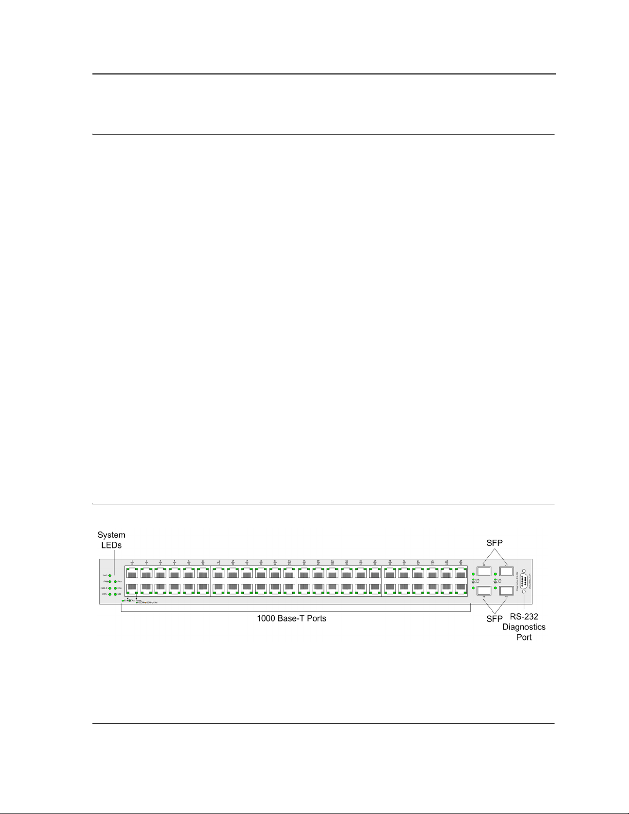
The D-Link DXS/DWS-3250 is a 48 port Gigabit Ethernet Managed Switch. The device contains 48 gigabit network ports and 4 SFP Ports on the front panel for network connectivity, and 2 stacking ports on the back panel.
The following figure illustrates the DXS-3250 front panel.
Figure 1: DXS/DWS-3250 Front Panel
Page 9
Page 11
DXS/DWS 3200 Series User Guide
The device front panel is configured as follows:
• 48 Gigabit Ethernet ports — RJ-45 ports designated as 10/100/1000Base-T . The RJ-45 ports are desig-
nated as ports Ports 1-48.
• RS-232 Console port — An asynchronous serial console port supporting the RS-232 electrical specification.
The port is used to connect the device to the console managing the device.
• 4 SFP Ports — There are four SFP port, which contains 1000Base-X (fiber) connections.
On the front panel there are the Port activity LEDs on each port with the system LEDs displayed separately.
DXS/DWS-3227 Front Panel
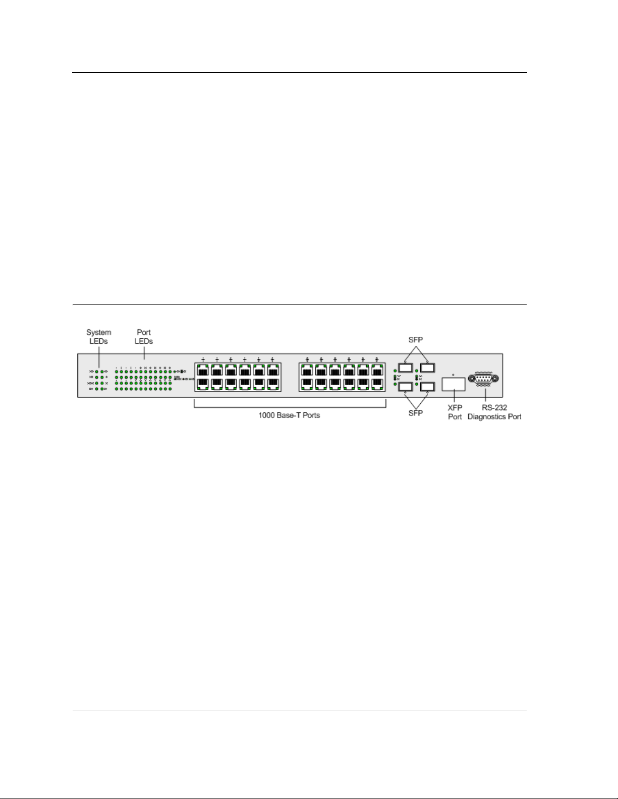
The D-Link DXS-3227 is a 24 port Gigabit Ethernet Managed Switch. The device contains 24 gigabit network
ports, 4 SFP ports and 1XFP 10G port on the front panel for network connectivity, and 2 optional stacking or uplink
module bays on the back panel.
The following figure illustrates the DXS-3227 front panel:
Figure 2: DXS/DWS-3227 Front Panel
The device front panel is configured as follows:
• 24 Gigabit Ethernet ports — RJ-45 ports designated as 10/100/1000Base-T . The RJ-45 ports are desig-
nated as ports Ports 1-24.
• RS-232 Console port — An asynchronous serial console port supporting the RS-232 electrical specification.
The port is used to connect the device to the console managing the device.
• 4 SFP Ports — There are four SFP port, which contains 1000Base-X (fiber) connections.
• XFP port — Hot-swappable optical interface for 10 Gigabit, Fibre Channel, Gigabit Ethernet, and other appli-
cations.
On the front panel there are the Port activity LEDs on each port with the system LEDs displayed separately.
DXS/DWS-3227P Front Panel
The D-Link DXS-3227P is a 24 port Gigabit Ethernet Managed Switch. The device contains 24 gigabit network
ports, 4 SFP ports and 1XFP 10G port on the front panel for network connectivity, and 2 optional stacking or uplink
module bays on the back panel. The DXS-3227P model also supports Power Over Ethenret.
Page 10
Page 12

Device Description
Viewing the Device
The following figure illustrates the DXS-3227 front panel:
Figure 3: DXS/DWS-3227P Front Panel
The device front panel is configured as follows:
• 24 Gigabit Ethernet ports — RJ-45 ports designated as 10/100/1000Base-T . The RJ-45 ports are desig-
nated as ports Ports 1-24.
• RS-232 Console port — An asynchronous serial console port supporting the RS-232 electrical specification.
The port is used to connect the device to the console managing the device.
• 4 SFP Ports — There are four SFP port, which contains 1000Base-X (fiber) connections.
• XFP port — Hot-swappable optical interface for 10 Gigabit and other applications.
On the front panel there are the Port activity LEDs on each port with the system LEDs displayed separately.
Back Panels
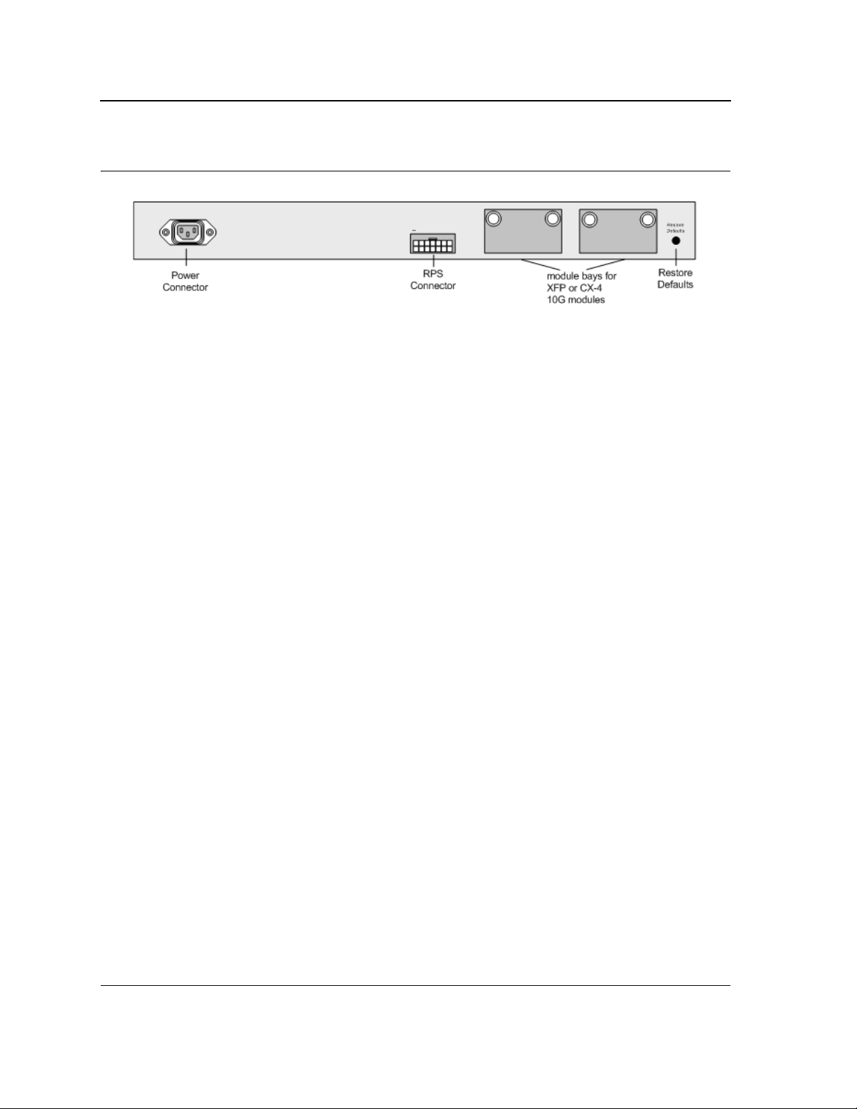
The following figures illustrate DXS-3250, DXS-3227 and DXS-3227P back panels:
Figure 4: DXS/DWS-3250 and DXS/DWS-3227 Back Panel
Page 11
Page 13
DXS/DWS 3200 Series User Guide
Figure 5: DXS/DWS-3227P Back Panel
The DXS-3200 series back panel is configured as follows:
• Reset Button — Resets the device. The Reset button does not extend beyond the device’s front panel sur-
face. This it to avoid accidental device resetting.
• 2 Stacking Connectors — The devices provide two stacking 12 Link(XG) interface ports.
•
RPS Connector — Redundant Power Supply (RPS) DC connector.
• Power Connector — AC power supply interface.
Ports Description
This section describes the device ports and includes the following topics:
• 1000Base-T Gigabit Ethernet Ports
• 10G XFP Fiber port
• CX-4 Copper Port
• SFP Ports
• Cable Specifications
1000Base-T Gigabit Ethernet Ports
The device contains a 1000 Base-TX Gigabit 24/48 port. The port is an RJ-45 port which supports half- and fullduplex mode 10/100/1000 Mbps.
10G XFP Fiber port
10Gigabit XFP fiber port. One fixed in DXS/DWS-3227/3227P models.
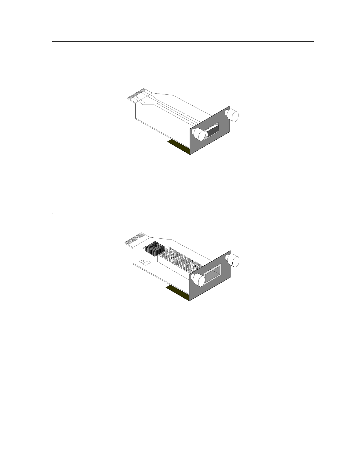
Optional Modules
The 3200 series have module bays located on the back panel into which optional modules (DEM-411X and DEM411XT) can be inserted and then provide additional 10Gigabit copper or fiber port.
CX-4 Copper Port
An optional 10Gigabit copper port. DEM-411T expansion module is inserted in one or two bays located on the
back panel.
The following figure describes the DEM - 411T module used for a copper port:
Page 12
Page 14
Device Description
Ports Description
Figure 6: CX-4 Expansion Module
10G XFP Fiber port
An optional 10Gigabit fiber port that can be inserted to the modules bays located on the back panel.
The following figure describes the DEM - 411X module used for a fiber port: Transceivers can be purchased separately from D-Link.
Figure 7: XFP Expansion Module
SFP Ports
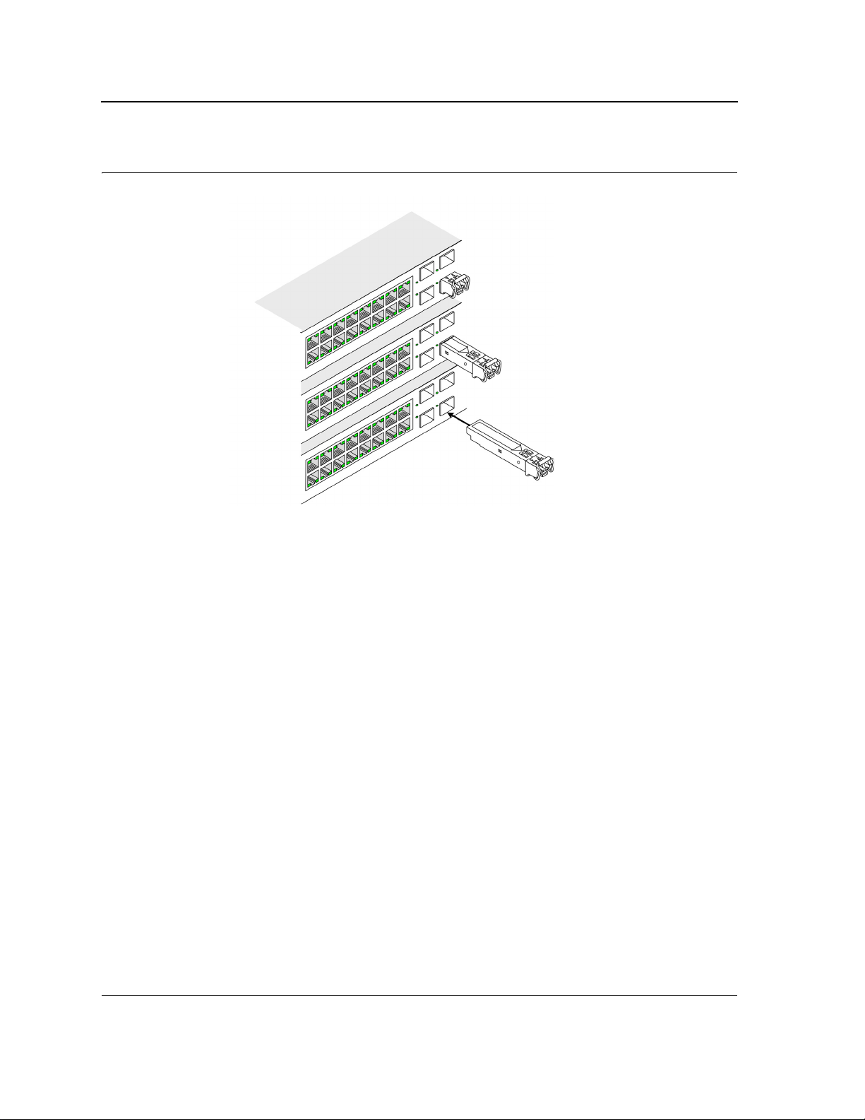
Small Form Factor Pluggable (SFP) Optical Transceivers are integrated duplex data mini-GBIC links for bi-directional communication over multimode optical fiber, designed for high-speed Fiber Channel data links. The SFP
port is designated as 1000Base-X.
The SFP (mini-GBIC) port can be removed and inserted as required. The following figure illustrates the mini-GBIC
insertion.
The following figure illustrates how to insert an SFP into the device:
Page 13
Page 15
DXS/DWS 3200 Series User Guide
Figure 8: Inserting an SFP into the Device
RS-232 Console Port
The RS-232 port is an asynchronous serial console port supporting the RS-232 electrical specification. The port is
used to connect the device to a console managing the device. This interface configuration is as follows:
• Eight data bits.
• One stop bit.
• No parity.
• Baud rate is 9600 (default). The user can change the rate from 115200 down to 9600 bps.
• Console speeds of 57600 and 115200.
Stacking Ports
The device has two optional stacking interface ports. One stacking port provides an Up connection, while the second provides a Down stacking connection. A 4X to 4X Infinidband Cable is used to connect devices in the stacking
configuration.
The DEM - 411S Stacking kit includes:
a) 0.5m CX-4 cable
b) Two DEM - 411T modules
The following figure descrives the DEM - 411S Stacking kit’s components:
Page 14
Page 16
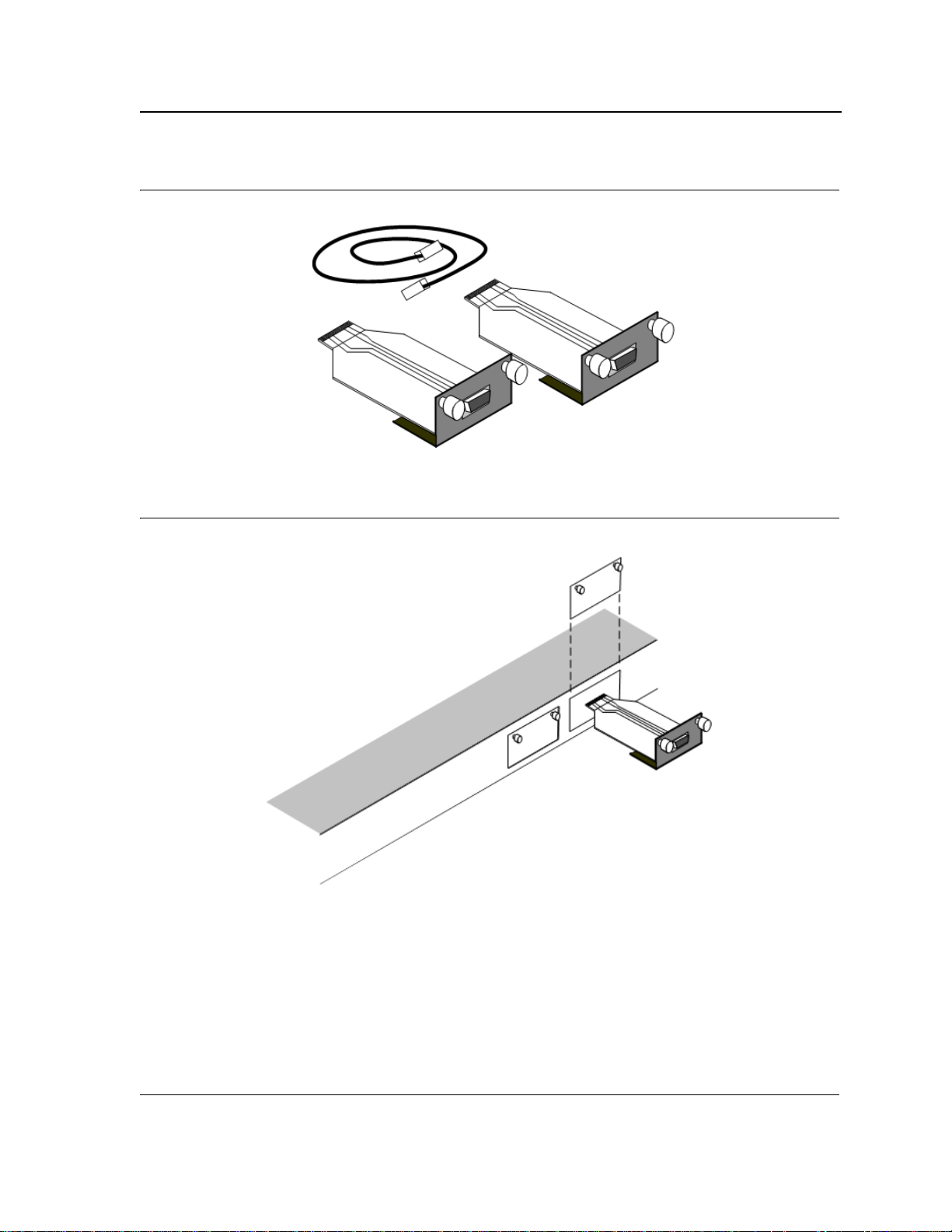
Figure 9: Stacking Kit (Optional)
Figure 10: Inserting a Module Into a Device
Device Description
Ports Description
To insert a module into a device:
1. Release bay cover bolts.
2. Remove bay cover.
3. Carefully Insert module into its proper slot.
4. Ensure that the module is inserted correctly.
5. Secure module bolts.
Page 15
Page 17

DXS/DWS 3200 Series User Guide
Cable Specifications
The following table contains the various cable specification for the DXS/DWS-3200 series:
Table 1: DXS-3250/DXS-3227P Cables and Optical Modules Specifications
Cable Type Description
1000Base-T UTP Cat. 5e (100 meters max.)
UTP Cat. 5 (100 meters max.)
EIA/TIA-568B 150-ohm STP (100 meters max.)
10G CX-4 10Gigabit copper port (Up to 15m)
1000BASE-LX Single-mode fiber module (10Km)
1000BASE-SX Multi-mode fiber module (550m)
1000BASE-LH Single-mode fiber module (40km)
1000BASE-ZX Single-mode fiber module (80km)
10Gigabit - XFP
Please refer to the D-Link
datasheet for DEM-421XT and
DEM-422XT should there be
any questions
Single/Multiple fiber XFP transceiver
LED Definitions
The device front panels contain Light Emitting Diodes (LED) that indicate the device status.The different LED
types are as follows:
• Port LEDs — Indicate each port status.
• SFP Ports — Indicate SFP port status.
• System — Indicating the device power supply status.
Port LEDs
1000Base-T Gigabit Ethernet RJ-45 Port LEDs
The LEDs on the three devices are differently indicated. The following figure illustrates the DXS-3250 port LEDs.
Page 16
Page 18
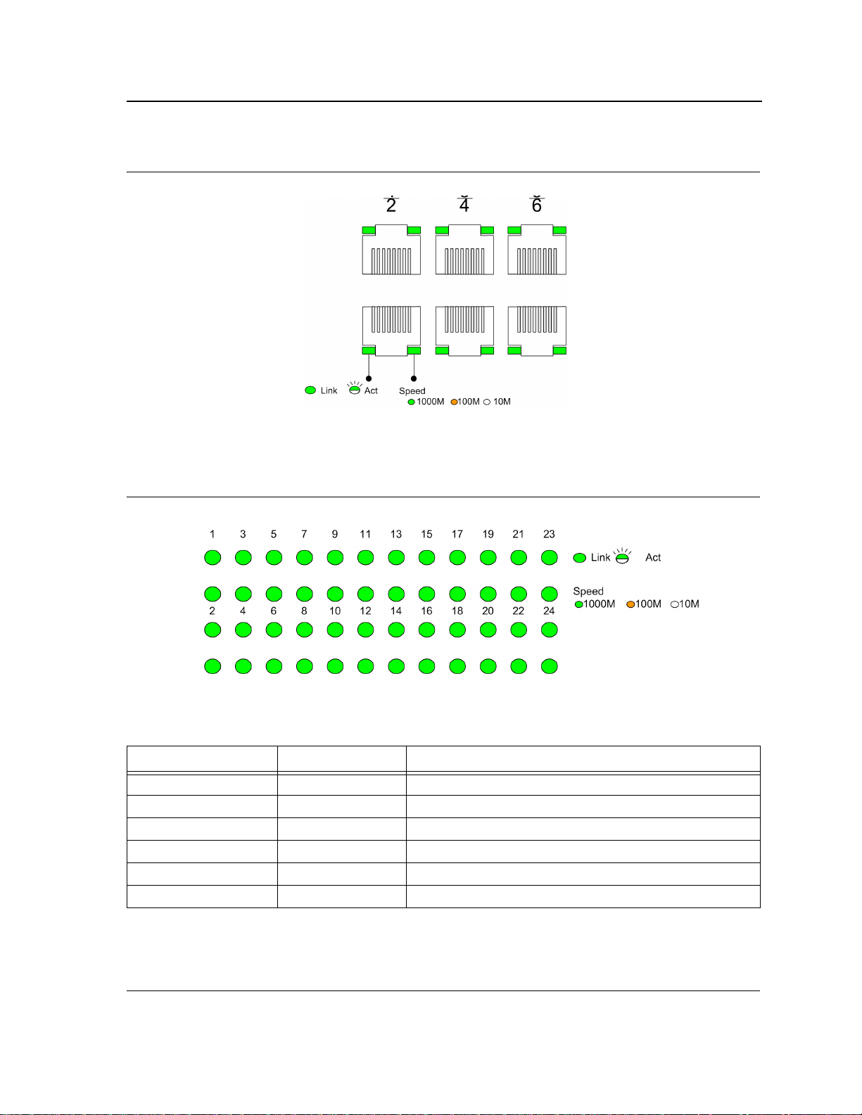
Figure 10: DXS-3250 1000Base-T Gigabit Ethernet RJ-45 Port LEDs
The DXS-3227 device has the LED indications on a LED panel on the left side of the device.
The following figure illustrates the port LEDs:
Device Description
LED Definitions
Figure 11: DXS-3227 1000Base-T Gigabit Ethernet RJ-45 Port LEDs
The RJ-45 ports on both devices have two LEDs, one for speed, and one for Link /activity. The LED indications are
described in the following table:
Table 2: 1000Base-T Gigabit Ethernet RJ-45 Port LED Indications
Port Description LED Indication Description
Speed Green A 1000-Mbps link is established on the port.
Amber A 100-Mbps link is established on the port.
Off A 10-Mbps link is established on the port.
Link/Activity LED Green A link is established on the port.
Flashing Green There is data transmission on the port.
Off No link is established on the port.
Page 17
Page 19
DXS/DWS 3200 Series User Guide
SFP LEDs
The following figure illustrates the port LEDs.
Figure 12: SFP LEDs
The Fiber ports each have one LED. The LED indications are described in the following table:
Table 3: SFP LED Indications
LED Indication Description
Green A link is established on the port.
Flashing Green There is data transmission on the port.
Off No link is established on the port.
System LEDs
The three devices have different system LEDs.
DXS-3250
The sytstem LEDs on the DXS-3250 device in on the left side of the device. The following figure illustrates the
DXS-3250 system LEDs:
Figure 13: DXS-3250 System LEDs
Page 18
Page 20
Device Description
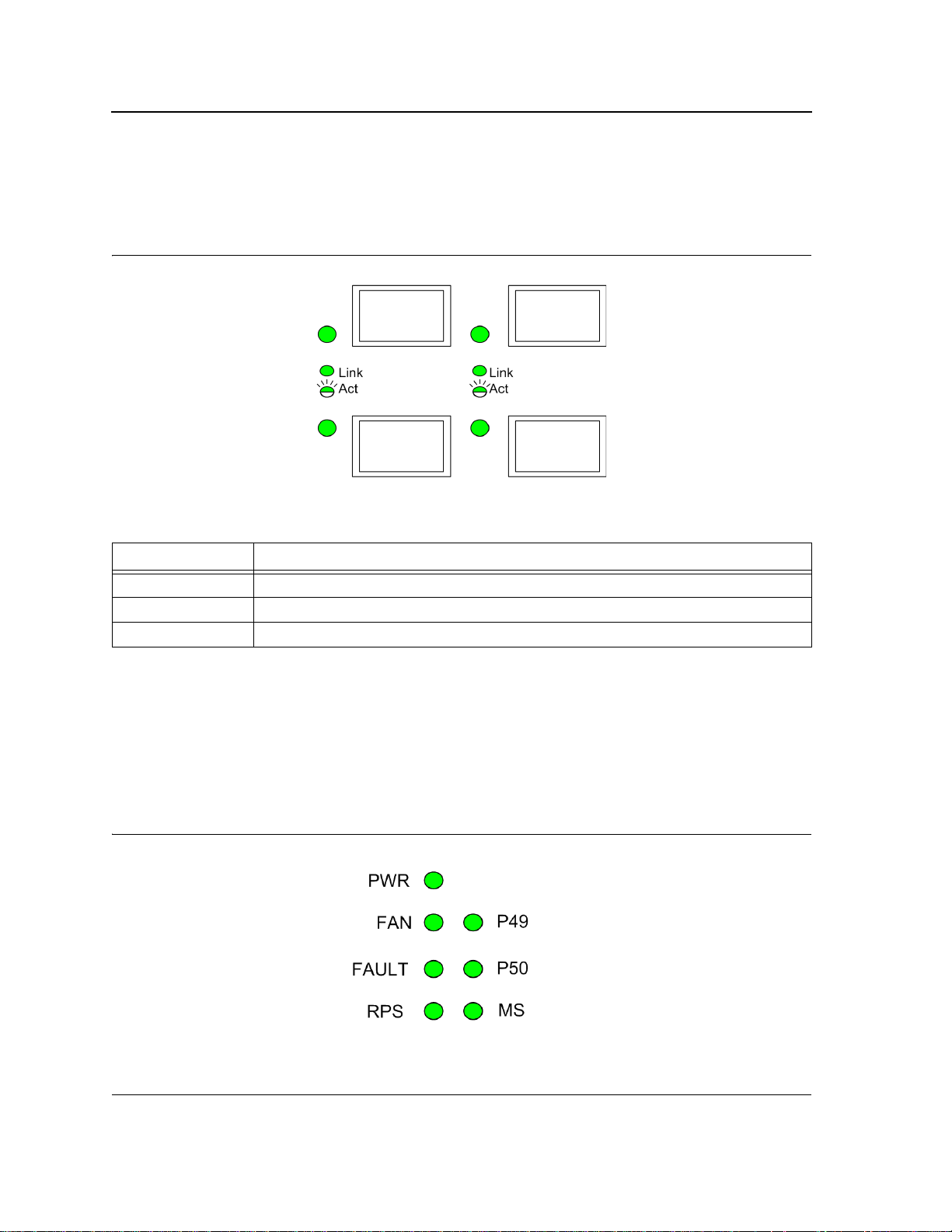
DXS/DWS-3227/3227P
The sytstem LEDs are on the DXS/DWS-3227/3227P device in on the left side of the device.
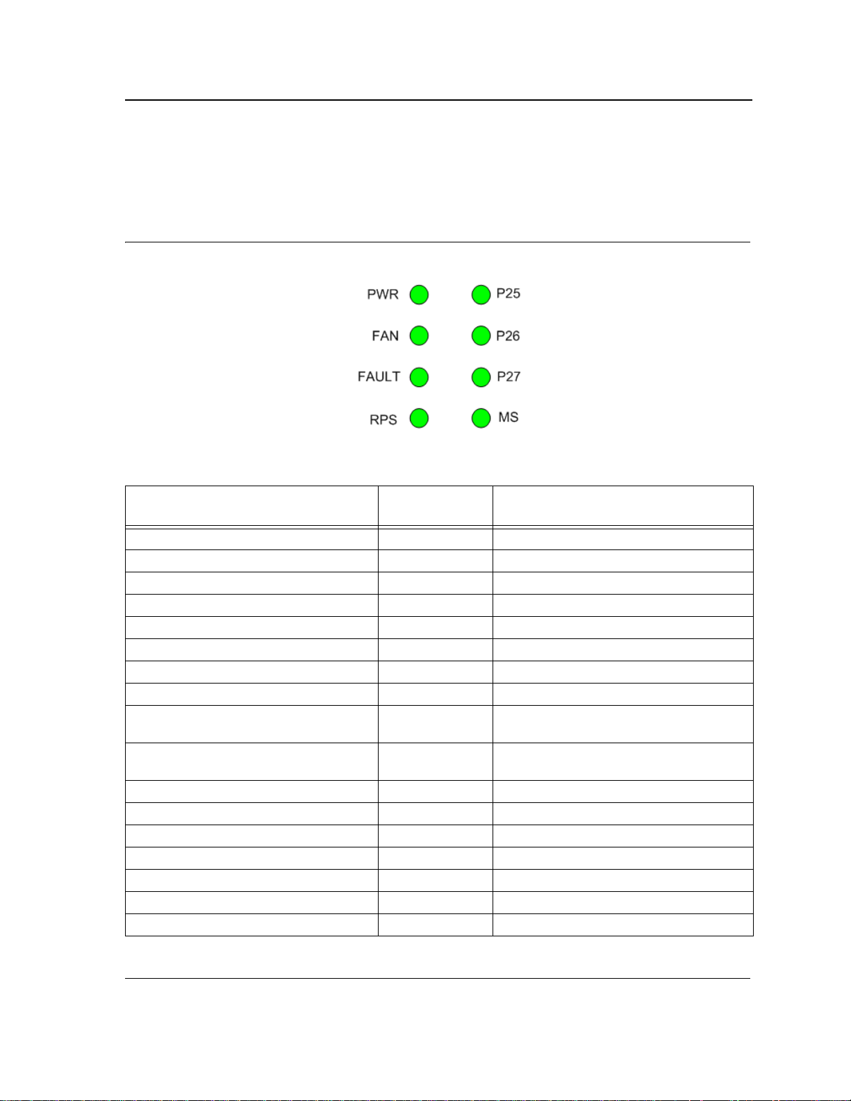
The following figure illustrates the DXS/DWS-3227/3227P system LEDs:
Figure 14: DXS/DWS-3227/3227P LEDs
The LED indications are described in the following table:
LED Definitions
Table 4: System’s LED Indications
LED Description LED
Indication
PWR Green The device is powered up.
Off The device is not powered up.
FAN Red Indicates a faulty fan.
Off All fans are functioning correctly.
Fault Red Flashing The device is currently running POST.
Red The device detected POST running error.
RPS Green The device is powered through the RPS.
Off The device is powered through the AC.
P49/P50 (DXS/DWS-3250) - Link/Act for
XG port
P25/P26/P27 (DXS/DWS-3227/3227P) Link/Act for XG port
MS Red Device is designated as the stack Master.
PoE Green Power is provided at this port
Green Link established on the port.
Green Link established on the port.
Green Flashing There is data transmission on the port.
Off No link is established on the port.
Green Device is designated as stack member.
Off Not a member of a stack (standalone).
Off Power is not provided at this port
Description
Page 19
Page 21
DXS/DWS 3200 Series User Guide
Table 4: System’s LED Indications
LED Description LED
Indication
Amber An error is occurred at this port
Off There is no error at this port
alternating Green
and Amber
Description
An error is occurred at this port
Cable, Port, and Pinout Information
This section describes the devices physical interfaces and provides information about cable connections. Stations
are connected to the device ports through the physical interface ports on the front panel. For each station, the
appropriate mode (Half/Full Duplex, Auto Negotiation) is set. The default is Auto Negotiation.
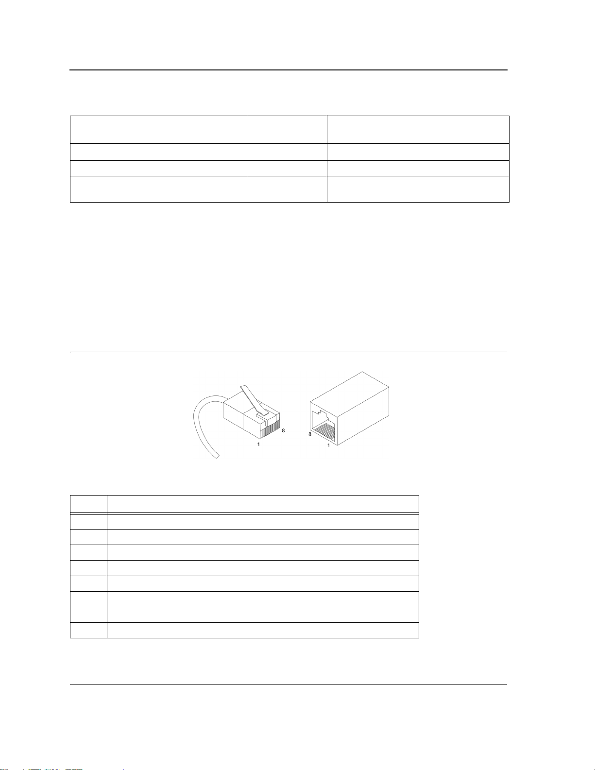
Pin Connections for the 10/100/1000 Ethernet Interface
The switching port can connect to stations wired in standard RJ-45 Ethernet station mode using straight cables.
Transmission devices connected to each other use crossed cables. The following figure illustrates the pin allocation.
Figure 15: RJ-45 Pin Allocation
The following table describes the pin allocation:
Table 5: RJ-45 Pin Connections for 10/100/1000 Base-TX
Pin Use
1
2
3
4
5
6
7
8 TxRx 4-
TxRx 1+
TxRx 1-
TxRx 2+
TxRx 2-
TxRx 3+
TxRx 3-
TxRx 4+
Page 20
Page 22
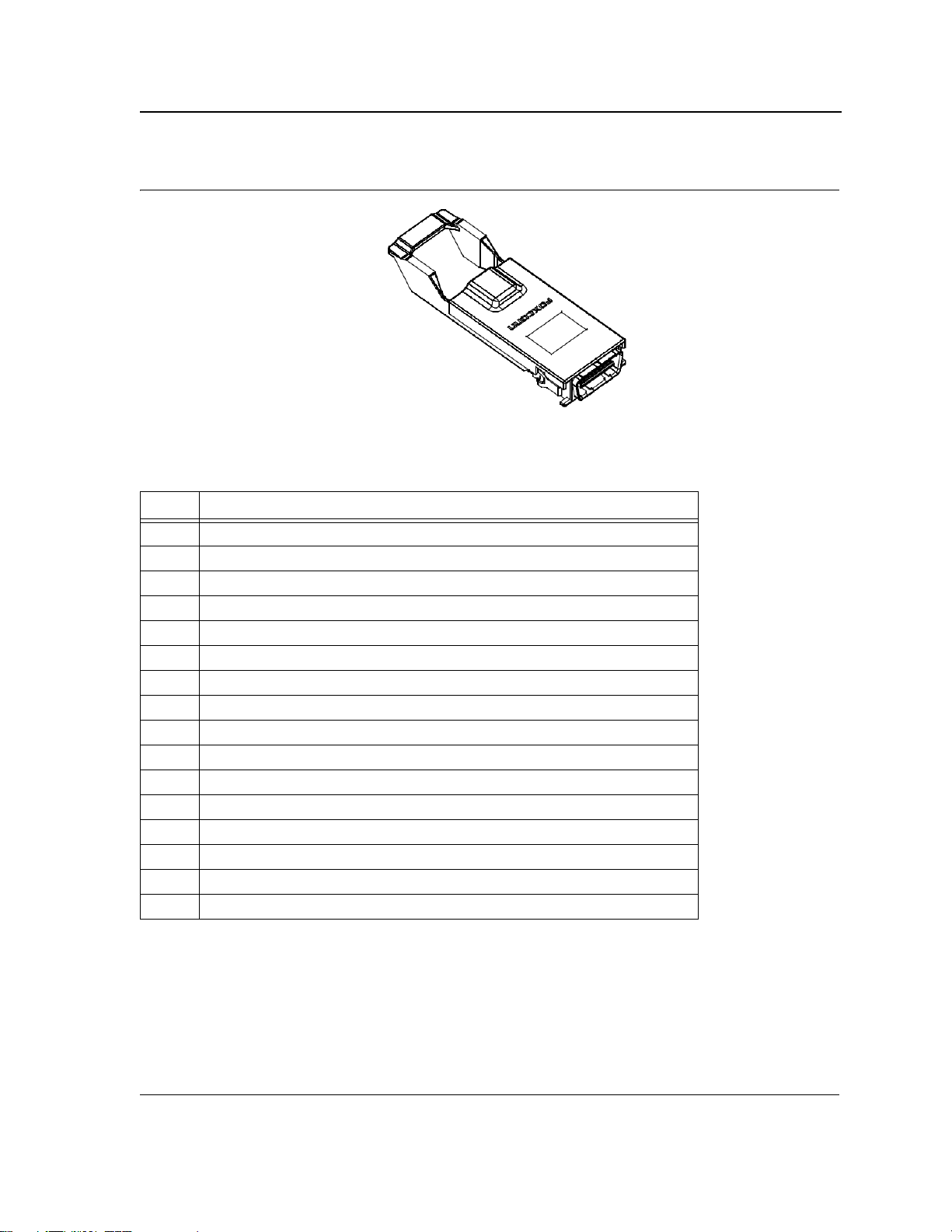
Figure 16: CX-4 Pin Allocation
The following table describes the pin allocation
Table 6: CX-4 Port Pin Connections
Pin Use
S1
2
3
4
5
6
7
8 Rx 3-
9
10
11
12
13
14
15
16 Tx 0+-
Rx 0+
Rx 0-
Rx 1+
Rx 1-
Rx 2+
Rx 2-
Rx 3+
Tx 3-
Tx 3+
Tx 2-
Tx 2+
Tx 1-
Tx 1+
Tx 0-
Device Description
Cable, Port, and Pinout Information
Page 21
Page 23
DXS/DWS 3200 Series User Guide
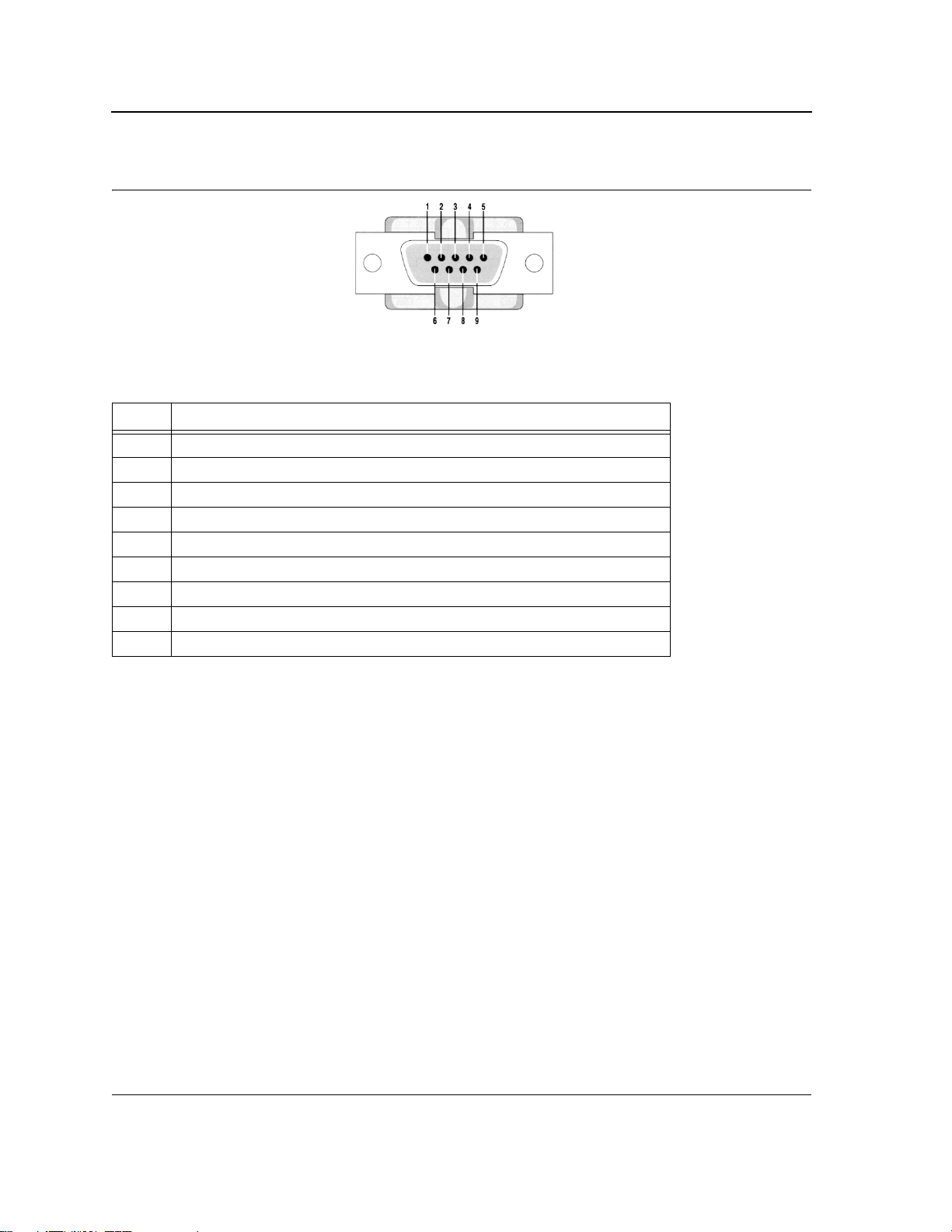
Figure 17: DB-9 Pin Allocation
The following table describes the pin allocation
Table 7: DB-9 Port Pin Connections
Pin Use
1
2
3
4
5
6
7
8 N/A
9 N/A
N/A
RXD
TXD
N/A
GND
N/A
N/A
Physical Dimensions
The device has the following physical dimensions:
DXS/DWS - 3250 / DXS/DWS - 3227P
• Width: 440 mm (17.32 inch)
• Depth: 430mm (16.93 inch)
• Height: 44 mm (1.77 inch)
DXS/DWS - 3227
• Width: 440 mm (17.32 inch)
• Depth: 310 mm (12.20 inch)
• Height: 44 mm (1.77 inch)
Page 22
Page 24

Device Description
Physical Dimensions
This page is left blank intentionally.
Page 23
Page 25

DXS/DWS 3200 Series User Guide
Page 24
Page 26

Mounting Device
Preparing for Installation
Section 2. Mounting Device
This section contains information for installing the device, and includes the following sections:
• Preparing for Installation
• Installing the Device
• Connecting the Device
• Rack Installation
Preparing for Installation
This section provides an explanation for preparing the installation site, and includes the following topics:
• Installation Precautions
• Site Requirements
• Unpacking
Installation Precautions
Warnings
• The surface on which the switch is placed should be adequately secured to prevent it from becoming
unstable and/or falling over.
• Ensure the power source circuits are properly grounded.
• Observe and follow service markings. Do not service any product except as explained in your system
documentation. Opening or removing covers marked with a triangular symbol with a lighting bolt may
cause electrical shock. These components are to be serviced by trained service technicians only.
• Ensure the power cable, extension cable, and/or plug is not damaged.
• Ensure the product is not exposed to water.
• Ensure the device is not exposed to radiators and/or heat sources.
• Do not push foreign objects into the device, as it may cause a fire or electric shock.
• Use the device only with approved equipment.
• Allow the product to cool before removing covers or touching internal equipment.
• Ensure the switch does not overload the power circuits, wiring, and over-current protection. To determine the possibility of overloading the supply circuits, add together the ampere ratings of all devices
installed on the same circuit as the device being installed. Compare this total with the rating limit for
the circuit. The maximum ampere ratings are usually printed on the switch, near their AC power connectors.
Cautions
• Ensure the air flow around the front, sides, and back of the switch is not restricted.
• Ensure the cooling vents are not blocked.
• Do not install the switch in an environment where the operating ambient temperature might exceed
40ºC (104ºF).
Page 25
Page 27

DXS/DWS 3200 Series User Guide
Site Requirements
The device is placed on a table-top. Before installing the unit, verify that the location chosen for installation meets
the following site requirements.
• General — Ensure that the power supply is correctly installed.
• Power — The unit is installed within 1.5 m (5 feet) of a grounded, easily accessible outlet 100-250 VAC, 50-
60 Hz.
• Clearance — There is adequate frontal clearance for operator access. Allow clearance for cabling, power
connections and ventilation.
• Cabling — The cabling is routed to avoid sources of electrical noise such as radio transmitters, broadcast
amplifiers, power lines and fluorescent lighting fixtures.
• Ambient Requirements — The ambient unit operating temperature range is 0 to 40ºC (32 to 104ºF) at a rel-
ative humidity of up to 95%, non-condensing. Verify that water or moisture cannot enter the device casing.
Unpacking
This section contains information for unpacking the device, and includes the following topics:
• Package Contents
• Unpacking Essentials
Package Contents
While unpacking the device, ensure that the following items are included:
• The device
• Four rubber feet with adhesive backing
• Rack kit
• An AC power cable
• Console RS-232 cable with DB-9 connector
• Documentation CD
Unpacking Essentials
Note
Before unpacking the device, inspect the package and report any evidence of damage immediately.
To unpack the device perform the following:
1. It is recommended to put on an ESD wrist strap and attach the ESD clip to a metal surface to act as ground.
An ESD strap is not supplied with the device.
2. Place the container on a clean flat surface and cut all straps securing the container.
3. Open the container.
4. Carefully remove the device from the container and place it on a secure and clean surface.
5. Remove all packing material.
6. Inspect the product for damage. Report any damage immediately.
If any item is found missing or damaged, please contact your local D-Link reseller for replacement.
Page 26
Page 28
Mounting Device
Installing the Device
Installing the Device
The device can be installed on a flat surface or mounted in a rack. This section includes the following topics:
• Desktop or Shelf Installation
• Rack Installation
Desktop or Shelf Installation
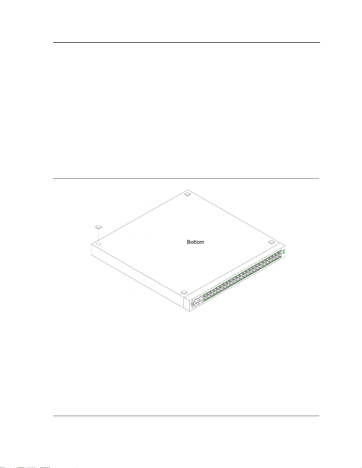
When installing the switch on a desktop or shelf, the rubber feet included with the device should first be attached.
Attach these cushioning feet on the bottom at each corner of the device.
Ensure the surface is be able to support the weight of the device and the device cables.
To install the device on a surface, perform the following:
1. Attach the rubber feet on the bottom of the device. The following figure illustrates the rubber feet installation
on the device.
Figure 18: Installing Rubber Feet
2. Set device down on a flat surface, while leaving 2 inches on each side and 5 inches at the back.
3. Ensure that the device has proper ventilation by allowing adequate space for ventilation between the device
and the objects around the device.
Rack Installation
The device can be mounted in an EIA standard-sized, 19-inch rack, which can be placed in a wiring closet with
other equipment. To install, the device the mounting brackets must first be attached on the devices’s sides.
Page 27
Page 29
DXS/DWS 3200 Series User Guide
Notes
• Disconnect all cables from the unit before mounting the device in a rack or cabinet.
• When mounting multiple devices into a rack, mount the devices from the bottom up.
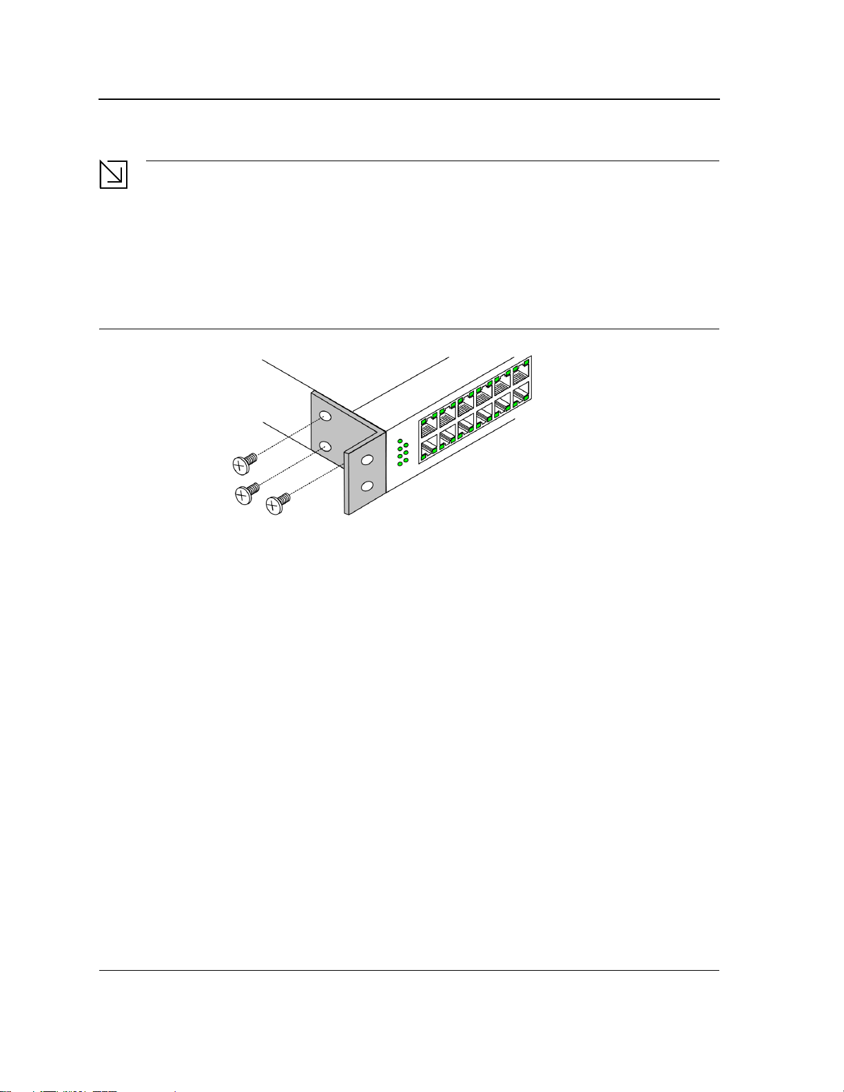
To install the device in a rack, perform the following:
1. Place the supplied rack-mounting bracket on one side of the device ensuring the mounting holes on the
device line up to the mounting holes on the rack mounting bracket. The following figure illustrates where to
mount the brackets.
Figure 19: Attaching the Mounting Brackets
2. Insert the supplied screws into the rack mounting holes and tighten with a screwdriver.
3. Repeat the process for the rack-mounting bracket on the other side of the device.
4. Insert the unit into the 19-inch rack ensuring the rack-mounting holes on the device line up to the mounting
hole on the rack. The following figure illustrates lining up and mounting the device in the rack.
Page 28
Page 30
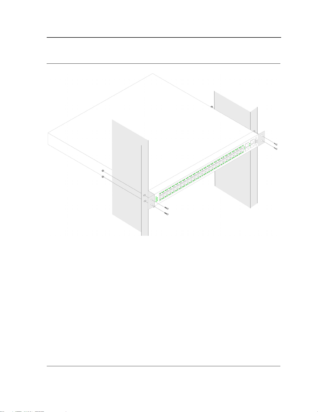
Figure 20: Mounting Device in a Rack
Mounting Device
Installing the Device
5. Secure the unit to the rack with the rack screws (not provided). Fasten the lower pair of screws before the
upper pair of screws. This ensures that the weight of the unit is evenly distributed during installation. Ensure
that the ventilation holes are not obstructed.
Page 29
Page 31

DXS/DWS 3200 Series User Guide
Connecting the Device
This section describes how to connect the device, and includes the following sections:
• Connecting the Switch to a Terminal
• AC Power Connection
Connecting the Switch to a Terminal
The device is connected to a terminal through an console port on the front panel, which enables a connection to a
terminal desktop system running terminal emulation software for monitoring and configuring the device.
The terminal must be a VT100 compatible terminal or a desktop or portable system with a serial port and running
VT100 terminal emulation software.
To connect a terminal to the device Console port, perform the following:
1. Connect a cable to the terminal running VT100 terminal emulation software.
2. Ensure that the terminal emulation software is set as follows:
a) Select the appropriate port to connect to the device.
b) Set the data rate to 9600 baud.
c) Set the data format to 8 data bits, 1 stop bit, and no parity.
d) Set flow control to none.
e) Under Properties, select VT100 for Emulation mode.
f) Select Terminal keys for Function, Arrow, and Ctrl keys. Ensure that the setting is for Terminal keys (not
Windows keys).
Note
When using HyperTerminal with Microsoft Windows 2000, ensure that you have Windows 2000 Service
Pack 2 or later installed. With Windows 2000 Service Pack 2, the arrow keys function properly in
HyperTerminal’s VT100 emulation. Go to www.microsoft.com for information on Windows 2000 service
packs.
3. Connect the cable to the console port on the device front panel.
AC Power Connection
To connect the power supply perform the following:
1. Using a 5-foot (1.5 m) standard power cable with safety ground connected, connect the power cable to the
AC main socket located on the back panel.
2. Connect the power cable to a grounded AC outlet.
3. Confirm that the device is connected and operating by checking that the Power Supply LED on the front panel
is green.
Page 30
Page 32

Initial Configuration
General Configuration Information
Section 3. Initial Configuration
This section describes the initial device configuration and includes the following topics:
• General Configuration Information
• Booting the Switch
• Configuration Overview
• Advanced Configuration
• Software Download and Reboot
• Configuring Stacking
• Startup Menu Functions
After completing all external connections, connect a terminal to the device to monitor the boot and other procedures. The order of installation and configuration procedures is illustrated in the following figure. For the initial configuration, the standard device configuration is performed. Other functions can be performed, but doing so
suspends the installation process and causes a system reboot.
Performing other functions is described later in this section.
General Configuration Information
Your device has predefined features and setup configuration.
Auto-Negotiation
Auto-negotiation allows a device to advertise modes of operation and share information with another device that
shares a point-to-point link segment. This automatically configures both devices to take maximum advantage of
their abilities.
Auto-negotiation is performed completely within the physical layers during link initiation, without any additional
overhead to either the MAC or higher protocol layers. Auto-negotiation allows the ports to do the following:
• Advertise their abilities
• Acknowledge receipt and understanding of the common modes of operation that both devices share
• Reject the use of operational modes that are not shared by both devices
• Configure each port for the highest-level operational mode that both ports can support
If connecting a port of the switch to the network interface card (NIC) of a terminal that does not support auto-negotiation or is not set to auto-negotiation, both the device port and the NIC must be manually set with the Web
browser interface or CLI commands to the same speed and duplex mode.
Note
If the station on the other side of the link attempts to auto-negotiate with a port that is manually configured
to full duplex, the auto-negotiation results in the station attempting to operate in half duplex. The resulting
mismatch may lead to significant frame loss. This is inherent in the auto-negotiation standard.
Page 31
Page 33

DXS/DWS 3200 Series User Guide
Device Port Default Settings
The following table describes the device port default settings:.
Table 8: Device Port Default Settings
Function Default Settings
Port speed and mode 1000M Auto-negotiation
Port forwarding state Enabled
Head of line blocking
prevention
Flow Control Off
Back Pressure Off
Note
These default settings can be modified once the device is installed.
The following is an example for changing the port speed on port g1 using CLI commands:
On (Enabled)
Console(config)# interface ethernet 1
Console(config-if)#
speed 100
The following is an example for enabling flow control on port g1 using CLI commands:
Console(config)#
Console(config-if)#
interface ethernet 1
flowcontrol on
The following is an example for enabling back pressure on port g1 using CLI commands.
Console(config)#
Console(config-if)#
interface ethernet 1
back-pressure
Booting the Switch
To boot the switch, perform the following:
1. Ensure that the device console is connected to a VT100 terminal device or VT100 terminal emulator.
2. Deactivate the AC power receptacle.
3. Connect the device to the AC receptacle.
4. Activate the AC power receptacle.
When the power is turned on with the local terminal already connected, the switch goes through Power On Self
Test (POST). POST runs every time the device is initialized and checks hardware components to determine if the
device is fully operational before completely booting. If a critical problem is detected, the program flow stops. If
POST passes successfully, a valid executable image is loaded into RAM. POST messages are displayed on the
terminal and indicate test success or failure.
Page 32
Page 34

Initial Configuration
Booting the Switch
As the switch boots, the bootup test first counts the device memory availability and then continues to boot. The following screen is an example of the displayed POST.
------ Performing the Power-On Self Test (POST) ------
UART Channel Loopback Test........................PASS
Testing the System SDRAM..........................PASS
Boot1 Checksum Test...............................PASS
Boot2 Checksum Test...............................PASS
Flash Image Validation Test.......................PASS
BOOT Software Version x.x.x.xx Built 07-Jan-200x 10:53:05
Processor: xxxxxx xxxxx xxxx, xx MByte SDRAM.
I-Cache 8 KB. D-Cache 8 KB. Cache Enabled.
Autoboot in 2 seconds - press RETURN or Esc. to abort and enter prom.
The boot process runs approximately 30 seconds.
The auto-boot message that appears at the end of POST (see the last lines) indicates that no problems were
encountered during boot.
During boot, the Startup menu can be accessed if necessary to run special procedures. To enter the Startup menu,
press <Esc> or <Enter> within the first two seconds after the auto-boot message is displayed. For information on
the Startup menu, see "Startup Menu Functions."
If the system boot is not interrupted by pressing <Esc> or <Enter>, the system continues operation by decompressing and loading the code into RAM. The code starts running from RAM and the list of numbered system ports
and their states (up or down) are displayed.
Page 33
Page 35

DXS/DWS 3200 Series User Guide
Note
The following screen is an example configuration.Items such as addresses, versions, and dates may differ
for each device.
Preparing to decompress...
Decompressing SW from image-1
638000
OK
Running from RAM...
*********************************************************************
*** Running SW Ver. x.x.x.x Date 11-Jan-200x Time 15:43:13 ***
*********************************************************************
HW version is
Base Mac address is: 00:00:b0:24:11:80
Dram size is: xxM bytes
Dram first block size is: 47104K bytes
Dram first PTR is: 0x1200000
Flash size is: xM
Devices on SMI BUS:
------------------smi dev id = 16, dev type=0xd0411ab, dev revision=0x1
Device configuration:
Prestera based - Back-to-back system
Slot 1 - DB-DX240-24G HW Rev. xx.xx
Tapi Version: xx.x.x-x
Core Version: xx.x.x-x
01-Jan-200x 01:01:22 %INIT-I-InitCompleted: Initialization task is
completed
Console> 01-Jan-200x 01:01:23 %LINK-I-Up: e1
01-Jan-200x 01:01:23 %LINK-W-Down: e2
01-Jan-200x 01:01:23 %LINK-I-Up: Vlan 1
01-Jan-200x 01:01:23 %LINK-W-Down: e4
.
.
.
01-Jan-200x 01:01:23 %LINK-W-Down: e46
01-Jan-200x 01:01:23 %LINK-W-Down: e47
01-Jan-200x 01:01:23 %LINK-W-Down: e48
After the switch boots successfully, a system prompt appears (console>) and the local terminal can be used to
begin configuring the switch. However, before configuring the switch, ensure that the software version installed on
the device is the latest version. If it is not the latest version, download and install the latest version. See "Software
Download and Reboot."
Configuration Overview
Before assigning a static IP address to the device, obtain the following information from the network administrator:
• A specific IP address allocated by the network administrator for the switch to be configured
• Network mask for the network
There are two types of configuration: Initial configuration consists of configuration functions with basic security
considerations, whereas advanced configuration includes dynamic IP configuration and more advanced security
considerations.
Page 34
Page 36

Initial Configuration
Configuration Overview
After making any configuration changes, the new configuration must be saved before rebooting. To save the configuration, enter the following CLI command:
Console# copy running-config startup-config
Initial Configuration
Initial configuration, which starts after the device has booted successfully, includes static IP address and subnet
mask configuration, and setting user name and privilege level to allow remote management. If the device is to be
managed from an SNMP-based management station, SNMP community strings must also be configured. The following configurations are completed:
• Static IP Address and Subnet Mask
• Static Route Configuration
• User Name
• SNMP Community strings
Static IP Address and Subnet Mask
IP interfaces can be configured on each port of the device. After entering the configuration command, it is recommended to check if a port was configured with the IP address by entering the “show ip interface” command.
The commands to configure the device are port specific.
To manage the switch from a remote network, a static route must be configured, which is an IP address to where
packets are sent when no entries are found in the device tables. The configured IP address must belong to the
same subnet as one of the device IP interfaces. To use the ip route command, the device mode must be changed
from switch to router.
To configure a static route, enter the command at the system prompt as shown in the following configuration
example where 101.101.101.101 is the specific management station, and 5.1.1.100 is the static route:
Console# configure
Console(config)# interface vlan 1
Console(config-if)#
Console(config-if)#
Console# ip route 192.168.2.0/24 100.1.1.33
ip address 100.1.1.1 255.255.255.0
exit
Note
100.1.1.33 is the IP address of the next hop that can be used to reach the management network
192.168.2.0.
Console#
Proxy ARP is disabled
IP Address I/F Type Directed
----------- -------- ----------- -------------
100.1.1.1/24 vlan 1 static disable
show ip interface
Broadcast
The above example is for router mode.
Page 35
Page 37

DXS/DWS 3200 Series User Guide
User Name
A user name is used to manage the device remotely, for example through SSH, Telnet, or the Web interface. To
gain complete administrative (super-user) control over the device, the highest privilege (15) must be specified.
Note
Only the administrator (super-user) with the highest privilege level (15) is allowed to manage the device
through the Web browser interface.
For more information about the privilege level, see the CLI Reference Guide.
The configured user name is entered as a login name for remote management sessions. To configure user name
and privilege level, enter the command at the system prompt as shown in the configuration example:
Console> enable
Console# configure
Console(config)# username admin password lee privilege 15
SNMP Community Strings
Simple Network Management Protocol (SNMP) provides a method for managing network devices. Devices supporting SNMP run a local software (agent). The SNMP agents maintain a list of variables, used to manage the
device. The variables are defined in the Management Information Base (MIB). The MIB presents the variables
controlled by the agent. The SNMP agent defines the MIB specification format, as well as the format used to
access the information over the network.
Access rights to the SNMP agents are controlled by access strings and SNMP community strings.
The device is SNMP-compliant and contains an SNMP agent that supports a set of standard and private MIB variables. Developers of management stations require the exact structure of the MIB tree and receive the complete
private MIBs information before being able to manage the MIBs.
All parameters are manageable from any SNMP management platform, except the SNMP management station IP
address and community (community name and access rights). The SNMP management access to the switch is
disabled if no community strings exist.
Note
The device switch is delivered with no community strings configured.
Page 36
Page 38

The following screen displays the default device configuration:
console# show snmp
Community-String Community-Access View name IP address
-------------------- ------------------ -------------- ------------
Community-String Group name IP address Type
------------------ ------------ ------------------- ------
Traps are enabled.
Authentication-failure trap is enabled.
Version 1,2 notifications
Target Address Type Community Version Udp Filter To Retries
Port name Sec
---------------- -------- ----------- ---------- ----- ------- ----- ---
------
Version 3 notifications
Target Address Type Username Security Udp Filter To Retries
Level Port name Sec
---------------- -------- ----------- -------- ----- ------- ----- -----
----
System Contact:
System Location:
Initial Configuration
Configuration Overview
The community-string, community-access, and IP address can be configured through the local terminal during the
initial configuration procedure.
The SNMP configuration options for the Community String are as follows:
• Access rights options: ro (read only), rw (read-and-write) or su (super).
• An option to configure IP address or not: If an IP address is not configured, it means that all community mem-
bers having the same community name are granted the same access rights.
Common practice is to use two community strings for the switch one (public community) with read-only access
and the other (private community) with read-write access. The public string allows authorized management stations to retrieve MIB objects, while the private string allows authorized management stations to retrieve and modify MIB objects.
During initial configuration, it is recommended to configure the device according to the network administrator
requirements, in accordance with using an SNMP-based management station.
To configure SNMP station IP address and community string(s) perform the following:
1. At the console prompt, enter the command
2. Enter the command
configure and press <Enter>.
3. In the configuration mode, enter the SNMP configuration command with the parameters including community
name (private), community access right (read and write) and IP address, as shown in the following example:
Enable. The prompt is displayed as #.
Page 37
Page 39

DXS/DWS 3200 Series User Guide
console# configure
console(config)# snmp-server community priate rw 10.1.1.1 view bobi
console(config)# exit
console# show snmp
Community-String Community-Access View name IP address
-------------------- ------------------ -------------- ----------- priate read write bobi 10.1.1.1
private read write bobi 10.1.1.2
Community-String Group name IP address Type
------------------ ------------ ------------------- ------
Traps are enabled.
Authentication-failure trap is enabled.
Version 1,2 notifications
Target Address Type Community Version Udp Filter To Retries
Port name Sec
---------------- -------- ----------- ---------- ----- ------- ----- ---
------
Version 3 notifications
Target Address Type Username Security Udp Filter To Retries
Level Port name Sec
---------------- -------- ----------- -------- ----- ------- ----- -----
----
System Contact:
System Location:
This completes the initial configuration of the device from a local terminal. The configured parameters enable further device configuration from any remote location.
Advanced Configuration
This section provides information about dynamic allocation of IP addresses and security management based on
the authentication, authorization, and accounting (AAA) mechanism, and includes the following topics:
• Configuring IP Addresses through DHCP
• Configuring IP Addresses through BOOTP
• Security Management and Password Configuration
When configuring/receiving IP addresses through DHCP and BOOTP, the configuration received from these servers includes the IP address, and may include subnet mask and default gateway.
Retrieving an IP Address From a DHCP Server
When using the DHCP protocol to retrieve an IP address, the device acts as a DHCP client. To retrieve an IP
address from a DHCP server, perform the following steps:
1. Select and connect any port to a DHCP server or to a subnet that has a DHCP server on it, in order to retrieve
the IP address.
2. Enter the following commands to use the selected port for receiving the IP address. In the following example,
the commands are based on the port type used for configuration.
– Assigning Dynamic IP Addresses:
console#
console(config)# interface ethernet 1
console(config-if)#
configure
ip address dhcp hostname <string>
Page 38
Page 40

Initial Configuration
Advanced Configuration
The interface receives the IP address automatically.
1. To verify the IP address, enter the show IP interface command at the system prompt as shown in the follow-
ing example.
Console# show ip interface
Gateway IP Address Activity status Type
-------- --------------- ------
10.6.41.97 Active Static
IP address I?F Type
------------- --------- -------
10.6.41.101/27 VLAN 1 Static
Notes
• The device configuration does not have to be deleted to retrieve an IP address for the DHCP server.
• When copying configuration files, avoid using a configuration file that contains an instruction to
enable DHCP on an interface that connects to the same DHCP server, or to one with an identical
configuration. In this instance, the switch retrieves the new configuration file and boots from it. The
device then enables DHCP as instructed in the new configuration file, and the DHCP instructs it to
reload the same file again.
Receiving an IP Address From a BOOTP Server
The standard BOOTP protocol is supported and enables the switch to automatically download its IP host configuration from any standard BOOTP server in the network. In this case, the device acts as a BOOTP client.
To retrieve an IP address from a BOOTP server:
1. Select and connect any port to a BOOTP server or subnet containing such a server, to retrieve the IP
address.
2. At the system prompt, enter the delete startup configuration command to delete the startup configuration from
flash. The device reboots with no configuration and in 60 seconds starts sending BOOTP requests. The
device receives the IP address automatically.
Note
When the device reboot begins, any input at the ASCII terminal or keyboard automatically cancels the
BOOTP process before completion and the device does not receive an IP address from the BOOTP
server.
Page 39
Page 41

DXS/DWS 3200 Series User Guide
The following example illustrates the process:
Console> enable
Console# delete startup-config
Startup file was deleted
Console#
You haven’t saved your changes. Are you sure you want to continue (y/n)[n]?
This command will reset the whole system and disconnect your current
session.Do you want to continue (y/n)[n]?
******************************************************
/*the device reboots */
reload
To verify the IP address, enter the show ip interface command. The device is now configured with an IP address.
Security Management and Password Configuration
System security is handled through the AAA (Authentication, Authorization, and Accounting) mechanism that
manages user access rights, privileges, and management methods. AAA uses both local and remote user databases. Data encryption is handled through the SSH mechanism.
The system is delivered with no default password configured; all passwords are user-defined. If a user-defined
password is lost, a password recovery procedure can be invoked from the Startup menu. The procedure is applicable for the local terminal only and allows a one-time access to the device from the local terminal with no password entered.
Configuring Security Passwords Introduction
The security passwords can be configured for the following services:
• Console
• Telnet
• SSH
• HTTP
• HTTPS
Passwords are user-defined.
When creating a user name, the default priority is "1," which allows access but not configuration rights. A priority of
"15" must be set to enable access and configuration rights to the device. Although user names can be assigned
privilege level 15 without a password, it is recommended to always assign a password. If there is no specified
password, privileged users can access the Web interface with any password.
Configuring an Initial Console Password
To configure an initial console password, enter the following commands:
Console(config)#
Console(config)# aaa authentication enable default line
Console(config)# line console
Console(config-line)# login authentication default
Console(config-line)# enable authentication default
Console(config-line)# password george
When initially logging on to a device through a console session, enter george at the password prompt.
When changing a device’s mode to enable, enter george at the password prompt.
aaa authentication login default line
Page 40
Page 42

Initial Configuration
Advanced Configuration
Configuring an Initial Telnet Password
To configure an initial Telnet password, enter the following commands:
Console(config)# aaa authentication login default line
Console(config)# aaa authentication enable default line
Console(config)# line telnet
Console(config-line)# login authentication default
Console(config-line)# enable authentication default
Console(config-line)# password bob
When initially logging onto a device through a Telnet session, enter bob at the password prompt.
When changing a device mode to enable, enter bob.
Configuring an Initial SSH password
To configure an initial SSH password, enter the following commands:
Console(config)#
Console(config)# aaa authentication enable default line
Console(config)# line ssh
Console(config-line)# login authentication default
Console(config-line)# enable authentication default
Console(config-line)# password jones
aaa authentication login default line
When initially logging onto a device through a SSH session, enter ”jones” at the password prompt.
When changing a device mode to enable, enter “jones”.
Configuring an Initial HTTP Password
To configure an initial HTTP password, enter the following commands:
Console(config)#
Console(config)# username admin password user1 level 15
ip http authentication local
Configuring an initial HTTPS Password
To configure an initial HTTPS password, enter the following commands:
Console(config)#
Console(config)# username admin password user1 level 15
Enter the following commands once when configuring to use a console, a Telnet, or an SSH session in order to
use an HTTPS session.
In the Web browser enable SSL 2.0 or greater for the content of the page to appear.
Console(config)# ip https server
Console(config)# crypto certificate 1 generate key-generate
Generating RSA private key, 1024 bit long modulus
Console(config)# ip https certificate 1
ip https authentication local
When initially enabling an http or https session, enter admin for user name and user1 for password.
Note
HTTP and HTTPS services require level 15 access and connect directly to the configuration level access.
Page 41
Page 43

DXS/DWS 3200 Series User Guide
Software Download and Reboot
Software Download through XModem
This section contains instructions for downloading device software (system and boot images) using XModem,
which is a data transfer protocol for updating back-up configuration files.
To download a boot file using XModem:
1. Enter the command “xmodem:boot”. The switch is ready to receive the file via the XModem protocol and displays text similar to the following:
Console# copy xmodem:boot
Please download program using XMODEM.
console#
2. Specify the path of the source file within 20 seconds. If the path is not specified within 20 seconds, the command times out.
To download a software image file using XModem:
1. Enter the command “xmodem:image”. The switch is ready to receive the file via the XModem protocol.
2. Specify the path of the source file to begin the transfer process. The following is an example of the information that appears:
Console# copy xmodem:image
Please download program using XMODEM
console#
Software Download Through TFTP Server
This section contains instructions for downloading device software (system and boot images) through a TFTP
server. The TFTP server must be configured before downloading the software.
The switch boots and runs when decompressing the system image from the flash memory area where a copy of
the system image is stored. When a new image is downloaded, it is saved in the other area allocated for the additional system image copy.
On the next boot, the switch decompresses and runs the currently active system image unless chosen otherwise.
To download an image through the TFTP server:
1. Ensure that an IP address is configured on one of the device ports and pings can be sent to a TFTP server.
2. Ensure that the file to be downloaded is saved on the TFTP server (the DOS file).
3. Enter the command “show version” to verify which software version is currently running on the device. The
following is an example of the information that appears:
Console# show version
SW version x.xx.xx (date xx-xxx-2004 time 13:42:41)Boot version
x.xx.x (date x-xxx-2003 time 15:12:20) HW version
4. Enter the command “show bootvar” to verify which system image is currently active. The following is an
example of the information that appears:
Console# show bootvar
Images currently available on the Flash Image-1 active (selected for
next boot)Image-2 not active
Console#
Page 42
Page 44

Initial Configuration
Software Download and Reboot
5. Enter the command “copy tftp://{tftp address}/{file name}image” to copy a new system image to the device.
When the new image is downloaded, it is saved in the area allocated for the other copy of system image
(image-2, as given in the example). The following is an example of the information that appears:
Console# copy tftp://176.215.31.3/file1 image Accessing file file1 on
176.215.31.3...
Loading file1 from
176.215.31.3:!!!!!!!!!!!!!!!!!!!!!!!!!!!!!!!!!!!!!!!!!!!!!!!!!!!!!!
!!!!!!!!!!!!!!!!!!!!!!!!!!!!!!!!!!!!!!!!!!!!!!!!!!!!!!!!!!!!!!!!!!!
!!!!!!!!!!!
Copy took 00:01:11 [hh:mm:ss]
Exclamation symbols indicate that a copying process is in progress. A period indicates that the copying process is timed out. Many periods in a row indicate that the copying process failed.
6. Select the image for the next boot by entering the boot system command. After this command, enter the com-
mand “show bootvar” to verify that the copy indicated as a parameter in the boot system command is
selected for the next boot. The following is an example of the information that appears:
Console# boot system image-2
Console# sh bootvar
Images currently available on the Flash Image-1 active Image-2 not
active (selected for next boot)
If the image for the next boot is not selected by entering the boot system command, the system boots from
the currently active image (image-1,as given in the example).
7. Enter the command “reload”. The following message is displayed:
Console# reload
This command will reset the whole system and disconnect your current
session.Do you want to continue (y/n)[n]?
8. Enter “Y” to reboot the switch.
Boot Image Download
Loading a new boot image from the TFTP server and programming it into the flash updates the boot image. The
boot image is loaded when the switch is powered on.
To download a boot file through the TFTP server:
1. Ensure that an IP address is configured on one of the device ports and pings can be sent to a TFTP server.
2. Ensure that the file to be downloaded (the .rfb file) is saved on the TFTP server.
3. Enter the command “show version” to verify which boot version is currently running on the device. The follow-
ing is an example of the information that appears:
Console# show version
SW version x.xx.xx (date xx-xxx-2004 time 13:42:41)Boot version
x.xx.xx (date xx-xx-2004 time 15:12:20)HW version xx.xx.xx (date xxxxx-2004 time 12:12:20)
4. Enter the command “copy tftp://{tftp address}/{file name} boot” to copy the boot image to the switch. The fol-
lowing is an example of the information that appears:
Console# copy tftp://176.215.31.3/6024_boot-10013.rfb
Erasing file
...done.!!!!!!!!!!!!!!!!!!!!!!!!!!!!!!!!!!!!!!!!!!!!!!!!!!!!!!!!!!!
!!!!!!!!!!!!!!!!!!!!!!!!!!!!!!!!!!!!!!!!!!!!!!!!!!!!!!!!!!!!!!!!!!!
!!!!!!Copy:393232 bytes copied in 00:00:05 [hh:mm:ss]
Page 43
Page 45

DXS/DWS 3200 Series User Guide
5. Enter the command “reload”. The following message is displayed:
Console# reload
This command will reset the whole system and disconnect your current
session. Do you want to continue (y/n)[n]?
6. Enter “Y” to reboot the switch.
Configuring Stacking
Configuring stacking is performed during the bootup process. To configure a device as part of a stack, the bootup
process must be interrupted straight after the Power On Self Test (POST).
To configure the device for stacking, perform the following:
1. Ensure that the device console is connected to a VT100 terminal device or VT100 terminal emulator.
2. Deactivate the AC power receptacle.
3. Connect the device to the AC receptacle.
4. Activate the AC power receptacle.
When the power is turned on with the local terminal already connected, the switch goes through POST. POST
runs every time the device is initialized and checks hardware components to determine if the device is fully
operational before completely booting. If a critical problem is detected, the program flow stops. If POST
passes successfully, a valid executable image is loaded into RAM. POST messages are displayed on the terminal and indicate test success or failure.
As the switch boots, the bootup test first counts the device memory availability and then continues to boot.
The following screen is an example of the displayed POST.
------ Performing the Power-On Self Test (POST) ------
UART Channel Loopback Test........................PASS
Testing the System SDRAM..........................PASS
Boot1 Checksum Test...............................PASS
Boot2 Checksum Test...............................PASS
Flash Image Validation Test.......................PASS
BOOT Software Version x.x.x.xx Built 07-Jan-200x 10:53:05
Processor: xxxxxx xxxxx xxxx, xx MByte SDRAM.
I-Cache 8 KB. D-Cache 8 KB. Cache Enabled.
Autoboot in 2 seconds - press RETURN or Esc. to abort and enter prom.
The boot process runs approximately 30 seconds.
The auto-boot message that appears at the end of POST (see the last lines) indicates that no problems were
encountered during boot.
5. Suspend the startup process by pressing
<Esc> or <Enter> within two seconds and the following message is
displayed:
Autoboot in 2 seconds -press RETURN or Esc.to abort and enter prom.
The Startup Menu is displayed and contains the following configuration functions:
Startup Menu
[1]Download Software
[2]Erase Flash File
[3]Erase Flash Sectors
[4]Password Recovery Procedure
[5]Enter Diagnostic Mode
[6]Stack Menu
[7]Back Enter your choice or press 'ESC' to exit:
Page 44
Page 46

6. On the Startup Menu, press “6”.
The following Stack Menu is displayed:
Stack menu
[1] Set unit number in stack
[2] Change stacking ports
[3] Stack info
[4] Back
Enter your choice or press 'ESC' to exit:
7. To Set a unit number press “1” on the Stack Menu.
The following prompt is displayed:
Enter your choice or press 'ESC' to exit:
Unit number in stack: [0-8,0 marks standalone unit] 1
Stacking Ports List - 1 2
Change stacking ports.
Enter #1 stacking port (valid range 1-48 and 49-50) use 'k' to keep
current setting (port 1):49
Enter #2 stacking port (valid range 1-48 and 49-50) use 'k' to keep
current setting (port 2):50
==== Press Enter To Continue ====
Initial Configuration
Configuring Stacking
8. Enter the first stacking port.
9. Enter the second stacking port.
10. Press <Enter>. The device is defined within the stack.
11. To change stacking ports press “2” on the Stack Menu.
The following prompt is displayed:
Enter your choice or press 'ESC' to exit:
Stacking Ports List - 1 2
Change stacking ports.
Enter #1 stacking port (valid range 1-48 and 49-50) use 'k' to keep
current setting (port 1):
k
Enter #2 stacking port (valid range 1-48 and 49-50) use 'k' to keep
current setting (port 2):
k
==== Press Enter To Continue ====
12. Enter the first stacking port.
13. Enter the second stacking port.
14. Press <Enter>. The device is defined within the stack.
15. For a stack info press “3” on the Stack Menu.
The following prompt is displayed:
Enter your choice or press 'ESC' to exit:
Stack Info:
----------Unit stack ID - 1
Stacking Ports List - 49 50
==== Press Enter To Continue ====
Page 45
Page 47

DXS/DWS 3200 Series User Guide
16. From the Stack menu, press “4”. The Startup menu is displayed.
17. From the Startup menu, press “10”. The Startup menu is closed and the device continues the Startup process.
Note
Once the device is booted up and operational in the stack, the configuration can be modified through the
Web or CLI.
Startup Menu Functions
Additional configuration functions can be performed from the Startup menu.
To display the Startup menu:
1. During the boot process, after the first part of the POST is completed press
onds after the following message is displayed:
Autoboot in 2 seconds -press RETURN or Esc.to abort and enter prom.
The Startup menu is displayed and contains the following configuration functions:
Startup Menu
[1]Download Software
[2]Erase Flash File
[3]Erase Flash Sectors
[4]Password Recovery Procedure
[5]Enter Diagnostic Mode
[6]Stack Menu
[7]Back Enter your choice or press 'ESC' to exit:
<Esc> or <Enter> within two sec-
The following sections describe the Startup menu options. If no selection is made within 25 seconds (default), the
switch times out and the device continues to load normally.
Only technical support personnel can operate the Diagnostics Mode. For this reason, the
Enter Diagnostic Mode
option of the Startup menu is not described in this guide.
Download Software
Use the software download option when a new software version must be downloaded to replace corrupted files,
update, or upgrade the system software.
To download software from the Startup menu:
1. On the Startup menu, press “1”.
The following prompt is displayed:
Downloading code using XMODEM
2. When using HyperTerminal, click
3. From the Transfer menu, click
4. Enter the file path for the file to be downloaded.
5. Ensure the protocol is defined as Xmodem.
6. Click
Send.
The software is downloaded. Software downloading takes several minutes. The terminal emulation application, such as HyperTerminal, may display the progress of the loading process.
After software downloads, the device reboots automatically.
Transfer on the HyperTerminal menu bar.
Send File. The Send File window is displayed.
Page 46
Page 48

Initial Configuration
Startup Menu Functions
Erase FLASH File
In some cases, the device configuration must be erased. If the configuration is erased, all parameters configured
via CLI, Web browser interface, or SNMP must be reconfigured.
To erase the device configuration:
1. From the Startup menu, press “2” within 6 seconds to erase flash file. The following message is displayed:
Warning! About to erase a Flash file.
Are you sure (Y/N)?y
2. Press “Y”.
Note
Do not press <Enter>.
The following message is displayed.
Write Flash file name (Up to 8 characters, Enter for none.):config
File config (if present) will be erased after system initialization
========Press Enter To Continue ========
3. Enter config as the name of the flash file. The configuration is erased and the device reboots.
4. Perform the switch’s initial configuration.
Erase FLASH Sectors
For troubleshooting purposes, the flash sectors may need to be erased. If the flash is erased, all software files
must be downloaded and installed again.
To erase the FLASH:
1. From the Startup menu, press “3” within 6 seconds. The following message is displayed:
Warning! About to erase Flash Memory! FLASH size =16252928.blocks =64
Are you sure (Y/N)
2. Confirm by pressing <Y>. The following message is displayed:
Enter First flash block (1 -63):
3. Enter the first flash block to be erased and press
Enter Last flash block (1 -63):
4. Enter the last flash block to be erased and press
Are you sure (Y/N)
5. Confirm by pressing
Erasing flash blocks 1 -63: Done.
<Y>. The following message is displayed:
<Enter>. The following message is displayed:
<Enter>. The following message is displayed:
Page 47
Page 49

DXS/DWS 3200 Series User Guide
Password Recovery
If a password is lost, use the Password Recovery option on the Startup menu. The procedure enables the user to
enter the device once without a password.
To recover a lost password for the local terminal only:
1. From the Startup menu, select “4” and press <Enter>. The password is deleted.
2. To ensure device security, reconfigure passwords for applicable management methods.
WLAN Licence Key
To upgrade a DXS- model into a DWS model with WLAN support, the user must enter a Licence key. The following
section describes the procedures for entering a Licence Key.
As the switch boots, the bootup test first counts the device memory availability and then continues to boot. The following screen is an example of the displayed POST.
------ Performing the Power-On Self Test (POST) ------
UART Channel Loopback Test........................PASS
Testing the System SDRAM..........................PASS
Boot1 Checksum Test...............................PASS
Boot2 Checksum Test...............................PASS
Flash Image Validation Test.......................PASS
BOOT Software Version x.x.x.xx Built 07-Jan-200x 10:53:05
Processor: xxxxxx xxxxx xxxx, xx MByte SDRAM.
I-Cache 8 KB. D-Cache 8 KB. Cache Enabled.
Autoboot in 2 seconds - press RETURN or Esc. to abort and enter prom.
The boot process runs approximately 30 seconds.
The auto-boot message that appears at the end of POST (see the last lines) indicates that no problems were
encountered during boot.
To enter a WLAN licence key perform the following:
1. Suspend the startup process by pressing
<Esc> or <Enter> within two seconds and the following message is
displayed:
Autoboot in 2 seconds -press RETURN or Esc.to abort and enter prom.
The Startup Menu is displayed and contains the following configuration functions:
Startup Menu
[1] Download Software
[2] Erase Flash File
[3] Password Recovery Procedure
[4] Enter Diagnostic Mode
[5] Set Terminal Baud-Rate
[6] Stack menu
[7] License menu
[8] Back
2. From the Startup Menu, press “7”.
Page 48
Page 50

The following Licence Menu is displayed:
License menu
[1] Add license
[2] Remove license
[3] Show license
[4] Back
Enter your choice or press 'ESC' to exit:
3. From the License Menu, press “1”.
The following prompt is displayed:
Enter licence:
4. Enter the licence key.
5. Press <Enter>
6. To remove a licence press “2” . The licence is removed (no prompt text appears).
7. To show a licence press “3”.
The following prompt is displayed:
Enter your choice or press 'ESC' to exit:
License number is:
N1-000000092948-25-0-A48D74999AC805DD
==== Press Enter To Continue ====
Initial Configuration
Startup Menu Functions
8. Press <Escape>
Page 49
Page 51

DXS/DWS 3200 Series User Guide
This page is left blank intentionally.
Page 50
Page 52

Section 4. Getting Started
This section provides an introduction to the user interface, and includes the following topics:
• Starting the D-Link Embedded Web Interface
• Understanding the D-Link Embedded Web Interface
• Using Screen and Table Options
• Resetting the Device
• Logging Off from the Device
Getting Started
Page 51
Page 53

DXS/DWS 3200 Series User Guide
Starting the D-Link Embedded Web Interface
Notes
• Disable the popup blocker before beginning device configuration using the EWS.
This section contains information on starting the D-Link Embedded Web interface. To access the D-Link user
interface:
1. Open an Internet browser.
2. Ensure that pop-up blockers are disabled. If pop-up blockers are enable, edit, add, and device information
messages may not open.
3. Enter the device IP address in the address bar and press Enter. The Enter Network Password Page opens:
Figure 21: Enter Network Password Page
4. Enter your user name and password.
Notes
• The device is configured with a user name that is admin and a password that is blank, and can be
configured without entering a password.
• Passwords are case sensitive.
• To operate the device, disable all pop-ups with a popup blocker.
5. Click . The D-Link Embedded Web Interface Home Page opens:
Page 52
Page 54

Notes
• The screen captures in this Guide represent the 48 port device. The Web pages in the 24 port device
may vary slightly.
Figure 22: D-Link Embedded Web Interface Home Page
Getting Started
Starting the D-Link Embedded Web Interface
Page 53
Page 55

DXS/DWS 3200 Series User Guide
Understanding the D-Link Embedded Web Interface
The D-Link Embedded Web Interface Home Page contains the following views:
• Port LED Indicators — Located at the top of the home page, the port LED indicators provide a visual repre-
sentation of the ports on the D-Link front panel.
• Tab A r e a — Located under the LED indicators, the tab area contains a list of the device features and their
components.
• Device View — Located in the main part of the home page, the device view provides a view of the device, an
information or table area, and configuration instructions.
Figure 23: D-Link Embedded Web Interface Components
The following table lists the user interface components with their corresponding numbers:
Table 9: Interface Components
View Description
1 Tree View Tree View provides easy navigation through the configurable device
features. The main branches expand to display the sub-features.
2 Device View
Device View provides information about device ports, current
configuration and status, table information, and feature
components. Device View also displays other device information
and dialog boxes for configuring parameters.
Page 54
Page 56

Getting Started
Understanding the D-Link Embedded Web Interface
Table 9: Interface Components
View Description
3 Tab Area The Tab Area enables navigation through the different device fea-
tures. Click the tabs to view all the components under a specific feature.
4 Zoom View Provides a graphic of the device on which D-Link Web Interface
runs.
5 D-Link Web Interface Information Tabs
This section provides the following additional information:
Provide access to online help, and contain information about the
EWS.
• Device Representation — Provides an explanation of the D-Link user interface buttons, including both man-
agement buttons and task icons.
• Using the D-Link Embedded Web Interface Management Buttons — Provides instructions for adding,
modifying, and deleting configuration parameters.
Device Representation
The D-Link Embedded Web Interface Home Page contains a graphical panel representation of the device.
Figure 24: Device Representation
Page 55
Page 57

DXS/DWS 3200 Series User Guide
Using the D-Link Embedded Web Interface Management Buttons
Configuration Management buttons and icons provide an easy method of configuring device information, and
include the following:
Table 10: D-Link Web Interface Configuration Buttons
Button Button Name Description
Clear Logs Clears system logs.
Create
Edit Modifies configuration settings.
Submit
Test Performs cable tests.
Query Queries the device table.
Table 11: D-Link Web Interface Information Tabs
Tab Tab Name Description
Help Opens the online help.
Logout Opens the Logout page.
Enables creation of configuration
entries.
Saves configuration changes to the
device.
Page 56
Page 58

Getting Started
Using Screen and Table Options
Using Screen and Table Options
D-Link contains screens and tables for configuring devices. This section contains the following topics:
• Adding Configuration Information
• Modifying Configuration Information
• Deleting Configuration Information
Adding Configuration Information
User-defined information can be added to specific D-Link Web Interface pages, by opening a new Add page. To
add information to tables or D-Link Web Interface pages:
1. Open an D-Link Web Interface page.
2. Click . An add page opens, such as the Add SNTP Interface Page:
Figure 25: Add SNTP Interface
3. Define the fields.
4. Click . The configuration information is saved, and the device is updated.
Modifying Configuration Information
1. Open The D-Link Embedded Web Interface page.
2. Select a table entry.
3. Click . A modification page, such as the IP Interface Settings Page opens:
Page 57
Page 59

DXS/DWS 3200 Series User Guide
Figure 26: IP Interface Settings Page
4. Modify the fields.
5. Click . The fields are modified, and the information is saved to the device.
Deleting Configuration Information
1. Open The D-Link Embedded Web Interface page.
2. Select a table row.
3. Select the Remove checkbox.
4. Click . The information is deleted, and the device is updated.
Page 58
Page 60

Resetting the Device
The Reset page enables resetting the device from a remote location.
Note
To prevent the current configuration from being lost, save all changes from the running configuration file
to the startup configuration file before resetting the device. For instructions, see Copying Files.
To reset the device:
1. Click System > General > Reset. The Reset page opens.
Figure 27: Reset Page
Getting Started
Resetting the Device
2. Click . A confirmation message is displayed.
3. Click . The device is reset, and a prompt for a user name and password is displayed.
4. Enter a user name and password to reconnect to the web Interface.
Page 59
Page 61

DXS/DWS 3200 Series User Guide
Logging Off from the Device
1. Click . The Logout Page opens.
2. Click . The D-Link Embedded Web Interface Home Page closes.
Page 60
Page 62

Managing Device Information
Defining the System Description
Section 5. Managing Device Information
This section contains information for setting general system information, and includes the following sections:
• Defining the System Description
• Defining Advanced System Settings
Defining the System Description
The System Description Page contains parameters for configuring general device information, including the system name, location, and contact, the system MAC Address, System Object ID, System Up Time, and MAC
addresses, and both software, boot, and hardware versions. To define the general system information:
1. Click System > General > Description. The System Description Page opens:
Figure 28: System Description Page
The System Description Page contains the following fields:
• Model Name — Displays the device model number and name.
• System Name — Defines the user-defined device name. The field range is 0-160 characters.
• System Location — Defines the location where the system is currently running. The field range is 0-160
characters.
• System Contact — Defines the name of the contact person. The field range is 0-160 characters.
Page 61
Page 63

DXS/DWS 3200 Series User Guide
• System Object ID — Displays the vendor’s authoritative identification of the network management sub-
system contained in the entity.
• System Up Time — Displays the amount of time since the most recent device reset. The system time is dis-
played in the following format: Days, Hours, Minutes, and Seconds. For example, 41 days, 2 hours, 22 minutes and 15 seconds.
• Base MAC Address — Displays the device MAC address.
• Hardware Version — Displays the installed device hardware version number.
• Software Version — Displays the installed software version number.
• Boot Version — Displays the current boot version running on the device.
Page 62
Page 64

Managing Device Information
Defining Advanced System Settings
Defining Advanced System Settings
The Mode Page allows network managers to enable Jumbo Frames on the device. Jumbo Frames enable the
transportation of identical data in fewer frames. This ensures less overhead, lower processing time, and fewer
interruptions.
To define advanced system settings:
1. Click System > General > Mode. The Mode Page opens.
Figure 29: Mode Page
The Mode Page contains the following field:
• Enable Jumbo Frames — Indicates if Jumbo Frames are enabled on the device. Maximum packet length
supported is 10Kb. The possible field values are:
– Checked — Enables Jumbo Frames on the device.
– Unchecked — Disables Jumbo Frames on the device.
2. Check the Enable Jumbo Frames field.
3. Click . Jumbo frames are enabled on the device.
Note
New settings will take effect only after resetting the device
Page 63
Page 65

DXS/DWS 3200 Series User Guide
This page is left blank intentionally.
Page 64
Page 66

Managing Power over Ethernet Devices
Section 6. Managing Power over Ethernet Devices
Power over Ethernet (PoE) provides power to devices over existing LAN cabling, without updating or modifying
the network infrastructure. Power over Ethernet removes the necessity of placing network devices next to power
sources. Power over Ethernet can be used with:
• IP Phones
• Wireless Access Points
• IP Gateways
• PDAs
• Audio and video remote monitoring
Powered Devices are devices which receive power from the device power supplies, for example IP phones. Powered Devices are connected to the device via Ethernet ports.
PoE is enabled for the DXS-3227P only.
This section includes the following topics:
• Defining PoE System Information
• Displaying and Editing PoE System Information
Page 65
Page 67

DXS/DWS 3200 Series User Guide
Defining PoE System Information
The PoE Properties Page contains system PoE information for enabling PoE on the device, monitoring the current
power usage, and enabling PoE traps.To enable PoE on the device:
1. Click the System > Power over Ethernet > Properties tab. The PoE Properties Page opens:
Figure 30: PoE Properties Page
The PoE Properties Page contains the following fields:
• Unit No. — Indicates the stacking member for which the POE is configured.
• Nominal Power — Indicates the actual amount of power the device can supply. The field value is displayed
in Watts.
• Power Status — Indicates the inline power source status. The possible field values are:
– On — Indicates that the power supply unit is functioning.
– Off — Indicates that the power supply unit is not functioning.
– Faulty — Indicates that the power supply unit is functioning, but an error has occurred. For example, a
power overload or a short circuit.
• Consumed Power — Indicates the amount of the power used by the device. The field value is displayed in
Watts.
• System Usage Threshold — Indicates the percentage of power consumed before an alarm is generated.
The field value is 1-99 percent. The default is 95 percent.
• Enable Traps — Indicate if PoE device traps are enabled. The possible field values are:
– Checked — Enables PoE traps on the device.
– Unchecked — Disables PoE traps on the device.This is the default value.
2. Modify the Unit No., Power Status, and Powered Device fields.
Page 66
Page 68

Managing Power over Ethernet Devices
Defining PoE System Information
3. Define the Unit No. and the System Usage Threshold field.
4. Check the Trap s checkbox.
5. Click . The system PoE parameters are defined, and the device is updated.
Page 67
Page 69

DXS/DWS 3200 Series User Guide
Displaying and Editing PoE System Information
The PoE Interface Page displays system PoE information on the device, monitoring the current power usage, and
enabling PoE traps. To display system PoE information on the device:
1. Click the System > Power over Ethernet > Interface tab. The PoE Interface Page opens:
Figure 31: PoE Interface Page
The PoE Interface Page contains the following fields:
• Unit No. — Indicates the stacking member for which the POE is configured.
• Port — Indicates the specific interface for which PoE parameters are defined, and assigned to the powered
interface connected to the selected port.
• Admin Status — Indicates the device PoE mode. The possible field values are:
– Auto — Enables the Device Discovery protocol, and provides power to the device using the PoE module.
The Device Discovery Protocol enables the device to discover Powered Devices attached to the device
interfaces, and to learn their classification. This is the default settings.
– Never — Disables the Device Discovery protocol, and stops the power supply to the device using the
PoE module.
• Operation Status — Indicates if the port is enabled to work on PoE. The possible field values are:
– On — Indicates the device is delivering power to the interface.
– Off — Indicates the device is not delivering power to the interface.
– Test F a il —Indicates the powered device test has failed. For example, a port could not be enabled and
cannot be used to deliver power to the powered device.
– Testing — Indicates the powered device is being tested. For example, a powered device is tested to
confirm it is receiving power from the power supply.
Page 68
Page 70

Managing Power over Ethernet Devices
Displaying and Editing PoE System Information
– Searching — Indicates that the device is currently searching for a powered device. Searching is the
default PoE operational status.
– Fault — Indicates that the device has detected a fault on the powered device. For example, the powered
device memory could not be read.
• Priority Level — Determines the port priority if the power supply is low. The port power priority is used if the
power supply is low. The field default is low. For example, if the power supply is running at 99% usage, and
port 1 is prioritized as high, but port 3 is prioritized as low, port 1 is prioritized to receive power, and port 3 may
be denied power. The possible field values are:
– Low — Defines the PoE priority level as low. This is the default level.
– High — Defines the PoE priority level as high.
– Critical — Defines the PoE priority level as Critical. This is the highest PoE priority level.
• Powered Device — Provides a user-defined powered device description. The field can contain up to 24 char-
acters.
2. Click . The PoE Interface Edit Page opens:
Figure 32: PoE Interface Edit Page
In addition to the fields in the PoE Interface Page, the PoE Interface Edit Page contains the following additional
fields:
• Overload Counter — Indicates the total power overload occurrences.
• Short Counter — Indicates the total power shortage occurrences.
• Denied Counter — Indicates times the powered device was denied power.
• Absent Counter — Indicates the times the power supply was stopped to the powered device because the
powered device was no longer detected.
Page 69
Page 71

DXS/DWS 3200 Series User Guide
• Invalid Signature Counter — Indicate the times an invalid signature was received. Signatures are the
means by which the powered device identifies itself to the PSE. Signature are generated during powered
device detection, classification, or maintenance.
3. Modify the PoE Admin Status, Power Priority Level, and Powered Device fields.
4. Click . The system PoE parameters are edited, and the device is updated.
Page 70
Page 72

Managing Stacking
Section 7. Managing Stacking
Stacking provides multiple switch management through a single point as if all stack members are a single unit. All
stack members are accessed through a single IP address through which the stack is managed. The stack is can
be managed from the following:
• Web-based Interface
• SNMP Management Station
• Command Line Interface (CLI)
Devices support stacking up to eight units per stack, or can operate as stand-alone units.
During the Stacking setup, one switch is selected as the Stacking Master and another stacking member can be
selected as the Secondary Master. All other devices are selected as stack members, and assigned a unique Unit
ID.
Switch software is downloaded separately for each stack members. However, all units in the stack must be running the same software version.
Switch stacking and configuration is maintained by the Stacking Master. The Stacking Master detects and reconfigures the ports with minimal operational impact in the event of:
• Unit Failure
• Inter-unit Stacking Link Failure
• Unit Insertion
• Removing a Stacking Unit
This section provides an introduction to the user interface, and includes the following topics:
• Understanding the Stack Topology
• Stacking Failover Topology
• Exchanging Stacking Members
• Switching the Stacking Master
• Configuring Stacking
Page 71
Page 73

DXS/DWS 3200 Series User Guide
Understanding the Stack Topology
The 32XX series Stacked devices operate in a Ring topology. A stacked Ring topology is where all devices in the
stack are connected to each other forming a circle. Each stacked device accepts data and sends it to the device to
which it is physically connected. The packet continues through the stack until it reaches the destination port. The
system automatically discovers the optimal path on which to send traffic.
Figure 33: Stacking Ring Topology
Most difficulties incurred in Ring topologies occur when a device in the ring becomes non-functional, or a link is
severed. In a stack, the system automatically switches to a Stacking Failover topology without any system downtime. An SNMP message is automatically generated, but no stack management action is required. However, the
stacking link or stacking member must be repaired to ensure the stacking integrity.
After the stacking issues are resolved, the device can be reconnected to the stack without interruption, and the
Ring topology is restored.
Stacking Failover Topology
If a failure occurs in the stacking topology, the stack reverts to Stacking Failover Topology. In the Stacking Failover
topology, devices operate in a chain formation. The Stacking Master determines where the packets are sent. Each
unit is connected to two neighboring devices, except for the top and bottom units.
Stacking Members and Unit ID
Stacking Unit IDs are essential to the stacking configuration. The stacking operation is determined during the boot
process. The Operation Mode is determined by the Unit ID selected during the initialization process. For example,
if the user selected stand-alone mode, the device boots as a stand-alone device.
The device units are shipped with the default Unit ID of the stand-alone unit. If the device is operating as a standalone unit, all stacking LEDs are off. Once the user selects a different Unit ID, the default Unit ID not erased, and
remains valid, even if the unit is reset.
Unit ID 1 and Unit ID 2 are reserved for Master enabled units. Unit IDs 3 to 8 can be defined for stack members.
When the Master unit boots or when inserting or removing a stack member, the Master unit initiates a stacking discovering process.
Page 72
Page 74

Managing Stacking
Stacking Failover Topology
Notes
• If two members are discovered with the same Unit ID the stack continues to function, however only
the unit with the older join time joins the stack. A message is sent to the user, notifying that a unit failed
to join the stack.
Removing and Replacing Stacking Members
Stacking member 1 and Stacking member 2 are Stacking Master enabled units. Unit 1 and Unit 2 are either designated as Master Unit or Secondary Master Unit. The Stacking Master assignment is performed during the configuration process. One Master enabled stack member is elected Master, and the other Master enabled stack member
is elected Secondary Master, according to the following decision process:
• If only one Stacking Master enabled unit is present, it is elected Master.
• If two Stacking Masters enabled stacking members are present, and one has been manually configured as
the Stacking Master, the manually configured member is elected Stacking Master.
• If two Master enabled units are present and neither has been manually configured as the Stacking Master, the
one with the longer up-time is elected Stacking Master.
• If the two Master enabled stacking members are the same age, Unit 1 is elected Stacking Master.
Notes
• Two stacking member are considered the same age if they were inserted within the same ten minute
interval.
For example, Stack member 2 is inserted in the first minute of a ten-minute cycle, and Stack member 1 is inserted
in fifth minute of the same cycle, the units are considered the same age. If there are two Master enabled units that
are the same age, then Unit 1 is elected master.
The Stacking Master and the Secondary Master maintain a Warm Standby. The Warm Standby ensures that the
Secondary Master takes over for the Stacking Master if a failover occurs. This guarantees that the stack continues
to operate normally.
During the Warm Standby, the Master and the Secondary Master are synchronized with the static configuration
only. When the Stacking Master is configured, the Stacking Master must synchronize the Stacking Secondary
Master. The Dynamic configuration is not saved, for example, dynamically learned MAC addresses are not saved.
Each port in the stack has a specific Unit ID, port type, and port number, which is part of both the configuration
commands and the configuration files. Configuration files are managed only from the device Stacking Master,
including:
• Saving to the FLASH
• Uploading Configuration files to an external TFTP Server
• Downloading Configuration files from an external TFTP Server
Whenever a reboot occurs, topology discovery is performed, and the master learns all units in the stack. Unit IDs
are saved in the unit and are learned through topology discovery. If a unit attempts to boot without a selected Master, and the unit is not operating in stand-alone mode, the unit does not boot.
Configuration files are changed only through explicit user configuration. Configuration files are not automatically
modified when:
• Units are Added
• Units are Removed
• Units are reassigned Unit IDs
Page 73
Page 75

DXS/DWS 3200 Series User Guide
• Units toggle between Stacking Mode and Stand-alone Mode
Each time the system reboots, the Startup Configuration file in the Master unit is used to configure the stack. If a
stack member is removed from the stack, and then replaced with a unit with the same Unit ID, the stack member
is configured with the original device configuration. Only ports which are physically present are displayed in the DLink Web Management Interface home page, and can be configured through the web management system. Nonpresent ports are configured through the CLI or SNMP interfaces.
Exchanging Stacking Members
If a stack member with the same Unit ID replaces an existing Unit ID with the same Unit ID, the previous device
configuration is applied to the inserted stack member. If the new inserted device has either more than or less ports
than the previous device, the relevant port configuration is applied to the new stack member. For example:
Switching the Stacking Master
The Secondary Master replaces the Stacking Master if the following events occur:
• The Stacking Master fails or is removed from the stack.
• Links from the Stacking Master to the stacking members fails.
• A soft switchover is performed with either via web interface or the CLI.
Switching between the Stacking Master and the Secondary Master results in a limited service loss. Any dynamic
tables are relearned if a failure occurs. The running configuration file is synchronized between Stacking Master
and the Secondary Master, and continues running on the Secondary Master.
Page 74
Page 76

Managing Stacking
Configuring Stacking
Configuring Stacking
The Stack Page allows network managers to either reset the entire stack or a specific device. Device
configuration changes that are not saved before the device is reset are not saved. If the Stacking Master is reset, the entire stack is reset. To open the Stack Page:
•
Click System > General tab. The Stack Page opens.
Figure 34: Stack Page
The Stack Page contains the following fields:
•
Top Unit— Indicates the top most stacking member’s number. Possible values are Master and 1-8.
• Bottom Unit — Indicates the lower most stacking member’s number. Possible values are Master and 1-8.
• Stack Order — Displays the stacking unit order based on the Unit IDs.
• Neighbor 1 — Displays the selected stacking unit’s neighbor.
• Neighbor 2 — Displays the selected stacking unit’s neighbor.
• Switch Stack Control from Unit 2 to Unit 1 — Changes the stack control from the Backup Master to the
Stack Master. The possible field values are:
– Checked — Enables switching the stack control to the Stack Master.
– Unchecked — Maintains the current stacking control.
Switching Between Stack Masters:
1. Open the Stack Page.
2. Check the Switch Stack Control from Unit 1 to Unit 2 check box.
3. Click . A confirmation message displays.
Page 75
Page 77

DXS/DWS 3200 Series User Guide
This page is left blank intentionally.
Page 76
Page 78

Configuring Device Security
Section 8. Configuring Device Security
This section provides access to security pages that contain fields for setting security parameters for ports, device
management methods, users, and server security. This section contains the following topics:
• Configuring Management Security
• Configuring Network Security
Page 77
Page 79

DXS/DWS 3200 Series User Guide
Configuring Management Security
This section provides information for configuring device management security. This section includes the following
topics:
• Configuring Authentication Methods
• Configuring Passwords
Configuring Authentication Methods
This section provides information for configuring device authentication methods. This section includes the topics:
• Defining Access Profiles
• Defining Profile Rules
• Defining Authentication Profiles
• Mapping Authentication Methods
• Defining RADIUS Settings
Page 78
Page 80

Configuring Device Security
Configuring Management Security
Defining Access Profiles
Access profiles are profiles and rules for accessing the device. Access to management functions can be limited to
user groups. User groups are defined for interfaces according to IP addresses or IP subnets. Access profiles contain management methods for accessing and managing the device. The device management methods include:
• All
• Telnet
• Secure Telnet (SSH)
• HTTP
• Secure HTTP (HTTPS)
• SNMP
Management access to different management methods may differ between user groups. For example, User
Group 1 can access the switch module only via an HTTPS session, while User Group 2 can access the switch
module via both HTTPS and Telnet sessions. The Access Profile Page contains the currently configured access
profiles and their activity status.
Assigning an access profile to an interface denies access via other interfaces. If an access profile is assigned to
any interface, the device can be accessed by all interfaces. To configure access profiles:
1. Click System > Management Security > Authentication > Access Profiles. The Access Profile Page
opens.
Figure 35: Access Profile Page
The Access Profile Page contains the following fields:
• Access Profile Name — Defines the access profile name. The access profile name can contain up to 32
characters.
• Current Active Active Profile — Defines the access profile currently active.
• Remove — Removes the selected access profile. The possible field values are:
– Checked — Removes the selected access profile. Access Profiles cannot be removed when Active.
Page 79
Page 81

DXS/DWS 3200 Series User Guide
– Unchecked — Maintains the access profiles.
2. Click . The Add Access Profile Page opens:
Figure 36: Add Access Profile Page
In addition to the fields in the Access Profile Page, the Add Access Profile Page contains the following fields:
• Access Profile Name — Defines the access profile name. The access profile name can contain up to 32
characters.
• Rule Priority — Defines the rule priority. When the packet is matched to a rule, user groups are either
granted permission or denied device management access. The rule number is essential to matching packets
to rules, as packets are matched on a first-fit basis. The rule priorities are assigned in the Profile Rules Page.
• Management Method — Defines the management method for which the rule is defined. Users with this
access profile can access the device using the management method selected. The possible field values are:
– All — Assigns all management methods to the rule.
– Teln et — Assigns Telnet access to the rule. If selected, users accessing the device using Telnet meeting
access profile criteria are permitted or denied access to the device.
– Secure Telnet (SSH) — Assigns SSH access to the rule. If selected, users accessing the device using
Telnet meeting access profile criteria are permitted or denied access to the device.
– HTTP — Assigns HTTP access to the rule. If selected, users accessing the device using HTTP meeting
access profile criteria are permitted or denied access to the device.
– Secure HTTP (HTTPS) — Assigns HTTPS access to the rule. If selected, users accessing the device
using HTTPS meeting access profile criteria are permitted or denied access to the device.
– SNMP — Assigns SNMP access to the rule. If selected, users accessing the device using SNMP
meeting access profile criteria are permitted or denied access to the device.
• Interface — Defines the interface on which the access profile is defined. The possible field values are:
– Port — Specifies the port on which the access profile is defined.
– LAG — Specifies the LAG on which the access profile is defined.
– VLAN — Specifies the VLAN on which the access profile is defined.
Page 80
Page 82

Configuring Device Security
Configuring Management Security
• Source IP Address — Defines the interface source IP address to which the access profile applies. The
Source IP Address field is valid for a subnetwork.
3. Define the Access Profile Name, Rule Priority, Management Method, Interface, Source IP Address, Network
Mask or Prefix Length, and Action fields.
4. Click . The access profile is created, and the device is updated.
Page 81
Page 83

DXS/DWS 3200 Series User Guide
Defining Profile Rules
Access profiles can contain up to 128 rules that determine which users can manage the switch module, and by
which methods. Users can also be blocked from accessing the device. Rules are composed of filters including:
• Rule Priority
• Interface
• Management Method
• Source IP Address
• Prefix Length
• Forwarding Action
The rule order is essential as packets are matched on a first-fit basis. To define profile rules:
1. Click System > Management Security > Authentication > Profile Rules. The Profile Rules Page opens.
Figure 37: Profile Rules Page
The Profile Rules Page contains the following fields:
• Access Profile Name — Displays the access profile to which the rule is attached.
• Priority — Defines the rule priority. When the packet is matched to a rule, user groups are either granted per-
mission or denied device management access. The rule number is essential to matching packets to rules, as
packets are matched on a first-fit basis.
• Interface — Indicates the interface type to which the rule applies. The possible field values are:
– Port — Attaches the rule to the selected port.
– LAG — Attaches the rule to the selected LAG.
– VLAN — Attaches the rule to the selected VLAN.
• Management Method — Defines the management method for which the rule is defined. Users with this
access profile can access the device using the management method selected. The possible field values are:
– All — Assigns all management methods to the rule.
Page 82
Page 84

Configuring Device Security
Configuring Management Security
– Teln et — Assigns Telnet access to the rule. If selected, users accessing the device using Telnet meeting
access profile criteria are permitted or denied access to the device.
– Secure Telnet (SSH) — Assigns SSH access to the rule. If selected, users accessing the device using
Telnet meeting access profile criteria are permitted or denied access to the device.
– HTTP — Assigns HTTP access to the rule. If selected, users accessing the device using HTTP meeting
access profile criteria are permitted or denied access to the device.
– Secure HTTP (HTTPS) — Assigns HTTPS access to the rule. If selected, users accessing the device
using HTTPS meeting access profile criteria are permitted or denied access to the device.
– SNMP — Assigns SNMP access to the rule. If selected, users accessing the device using SNMP
meeting access profile criteria are permitted or denied access to the device.
• Source IP Address — Defines the interface source IP address to which the rule applies.
• Prefix Length — Defines the number of bits that comprise the source IP address prefix, or the network mask
of the source IP address.
• Action —Defines the action attached to the rule. The possible field values are:
– Permit — Permits access to the device.
– Deny — Denies access to the device. This is the default.
• Remove — Removes rules from the selected access profiles. The possible field values are:
– Checked — Removes the selected rule from the access profile.
– Unchecked — Maintains the rules attached to the access profile.
2. Click . The Add Profile Rule Page opens:
Figure 38: Add Profile Rule Page
3. Define the Access Profile Name, Priority, Management Method, Interface, Source IP Address, Network Mask
or Prefix Length, and Action fields.
4. Click . The profile rule is added to the access profile, and the device is updated.
Page 83
Page 85

DXS/DWS 3200 Series User Guide
To modify a Profile Rule:
1. Click System > Management Security > Authentication > Profile Rules. The Access Profile Page opens
2. Click . The Profile Rules Setting Page opens:
3. Modify the fields.
4. Click . The profile rule is modified, and the device is updated.
Page 84
Page 86

Configuring Device Security
Configuring Management Security
Defining Authentication Profiles
Authentication profiles allow network administrators to assign authentication methods for user authentication.
User authentication can be performed either locally or on an external server. User authentication occurs in the
order the methods are selected. If the first authentication method is not available, the next selected method is
used. For example, if the selected authentication methods are RADIUS and Local, and the RADIUS server is not
available, then the user is authenticated locally. To define Authentication profiles:
1. Click System > Management Security > Authentication > Authentication Profiles. The Authentication
Profile Page opens.
Figure 39: Authentication Profile Page
The Authentication Profile Page contains the following fields:
• Profile Name — Contains a list of user-defined authentication profile lists to which user-defined authentica-
tion profiles are added.
• Methods — Defines the user authentication methods. The possible field values are:
– None — Assigns no authentication method to the authentication profile.
– Local — Authenticates the user at the device level. The device checks the user name and password for
authentication.
– RADIUS — Authenticates the user at the RADIUS server. For more information, see “Defining RADIUS
Settings."
– Line — Authenticates the user using a line password.
– Enable — Authenticates the user using an enable password.
– TACACS+ — Authenticates the user at the TACACS+
• Remove — Removes the selected authentication profile. The possible field values are:
– Checked — Removes the selected authentication profile.
– Unchecked — Maintains the authentication profiles.
Page 85
Page 87

DXS/DWS 3200 Series User Guide
2. Click . The Add Authentication Profile Page opens.
Figure 40: Add Authentication Profile Page
3. Define the Profile Method, Profile Name and Authentication Methods fields.
4. Click . The authentication profile is defined, and the device is updated.
To modify an authentication profile:
1. Click System > Management Security > Authentication > Authentication Profiles. The Authentication
Profile Page opens.
2. Click . The Authentication Profile Settings Page opens:
3. Select an authentication method from the Optional Methods list.
4. Click . The authentication method is selected, and the device is updated.
Page 86
Page 88

Configuring Device Security
Configuring Management Security
Mapping Authentication Methods
After authentication profiles are defined, they can be applied to management access methods. For example, console users can be authenticated by Authentication Profile List 1, while Telnet users are authenticated by Authentication Method List 2.
Authentication methods are selected using arrows. The order in which the methods are selected is the order by
which the authentication methods are used.
To map authentication methods:
1. Click System > Management Security > Authentication > Authentication Mapping. The Authentication
Mapping Page opens.
Figure 41: Authentication Mapping Page
The Authentication Mapping Page contains the following fields:
• Console — Indicates that Authentication profiles are used to authenticate console users.
• Tel net — Indicates that Authentication profiles are used to authenticate Telnet users.
• Secure Telnet (SSH) — Indicates that Authentication profiles are used to authenticate Secure Shell (SSH)
users. SSH provides clients secure and encrypted remote connections to a device.
• Secure HTTP — Indicates that Authentication methods used for Secure HTTP access. Possible field values
are:
Page 87
Page 89

DXS/DWS 3200 Series User Guide
– None — Indicates that no authentication method is used for access.
– RADIUS — Indicates that authentication occurs at the RADIUS server.
– TACACS+ — Indicates that authentication occurs at the TACACS+
– Local — Indicates that authentication occurs locally.
• HTTP — Indicates that Authentication methods are used for HTTP access. Possible field values are:
– None — Indicates that no authentication method is used for access.
– RADIUS — Indicates that Authentication occurs at the RADIUS server.
– TACACS+ — Indicates that authentication occurs at the TACACS+
– Local — Indicates that authentication occurs locally.
1. Define the Console, Telnet, and Secure Telnet (SSH) fields.
2. Map the authentication method in the Secure HTTP selection box.
3. Map the authentication method in the HTTP selection box.
4. Click . The authentication mapping is saved, and the device is updated.
Page 88
Page 90

Configuring Device Security
Configuring Management Security
Defining RADIUS Settings
Remote Authorization Dial-In User Service (RADIUS) servers provide additional security for networks. RADIUS
servers provide a centralized authentication method for web access.
The default parameters are user-defined, and are applied to newly defined RADIUS servers. If new default parameters are not defined, the system default values are applied to newly defined RADIUS servers.
To configure RADIUS servers:
1. Click System > Management Security > Authentication > RADIUS. The RADIUS Page opens:
Figure 42: RADIUS Page
The RADIUS Page contains the following fields:
• Retries — Defines the number of transmitted requests sent to the RADIUS server before a failure occurs.
Possible field values are 1-10. The default value is 3.
• Timeout for Reply — Defines the amount of time (in seconds) the device waits for an answer from the
RADIUS server before retrying the query, or switching to the next server. Possible field values are 1-30. The
default value is 3.
• Dead Time — Defines the default amount of time (in minutes) that a RADIUS server is bypassed for service
requests. The range is 0-2000. The default value is 0.
• Key String — Defines the default key string used for authenticating and encrypting all RADIUS-communica-
tions between the device and the RADIUS server. This key must match the RADIUS encryption.
• Source IP Address — Defines the default IP address of a device accessing the RADIUS server.
The RADIUS Page also contains the following fields:
• IP Address — Lists the RADIUS server IP addresses.
• Priority — Displays the RADIUS server priority. The possible values are 1-65535, where 1 is the highest
value. The RADIUS server priority is used to configure the server query order.
Page 89
Page 91

DXS/DWS 3200 Series User Guide
• Authentication Port — Identifies the authentication port. The authentication port is used to verify the
RADIUS server authentication. The authenticated port default is 1812.
• Number of Retries — Defines the number of transmitted requests sent to the RADIUS server before a failure
occurs. The possible field values are 1-10. Three is the default value.
• Timeout for Reply — Defines the amount of time (in seconds) the device waits for an answer from the
RADIUS server before retrying the query, or switching to the next server. The possible field values are 1-30.
Three is the default value.
• Dead Time — Defines the amount of time (in minutes) that a RADIUS server is bypassed for service
requests. The range is 0-2000. The default is 0 minutes.
• Key String — Defines the default key string used for authenticating and encrypting all RADIUS-communica-
tions between the device and the RADIUS server. This key must match the RADIUS encryption.
• Source IP Address — Defines the source IP address that is used for communication with RADIUS servers.
• Usage Type — Specifies the RADIUS server authentication type. The default value is All. The possible field
values are:
– Log in — Indicates the RADIUS server is used for authenticating user name and passwords.
– 802.1X — Indicates the RADIUS server is used for 802.1X authentication.
– All — Indicates the RADIUS server is used for authenticating user names and passwords, and 802.1X
port authentication.
• Remove— Removes a RADIUS server. The possible field values are:
– Checked — Removes the selected RADIUS server.
– Unchecked — Maintains the RADIUS servers.
2. Click . The Add Radius Server Page opens:
Figure 43: Add Radius Server Page
3. Define the fields.
4. Click . The RADIUS server is added, and the device is updated.
Page 90
Page 92

Configuring Device Security
Configuring Management Security
To edit RADIUS Server Settings:
1. Click System > Management Security > Authentication > Radius. The RADIUS Page opens.
2. Click . The RADIUS Server Settings Page opens:
Figure 44: RADIUS Server Settings Page
3. Define the Host IP Address, Priority, Source IP Address, Key String, Number of Retries, Authentication Port,
Timeout for Reply, Dead Time, and Usage Type fields.
4. Click . The RADIUS server settings are saved, and the device is updated.
Page 91
Page 93

DXS/DWS 3200 Series User Guide
Defining TACACS+ Authentication
Terminal Access Controller Access Control System (TACACS+) provides centralized security user access validation. The sytem supports up-to 4 TACACS+ servers.
TACACS+ provides a centralized user management system, while still retaining consistency with RADIUS and
other authentication processes. TACACS+ provides the following services:
• Authentication — Provides authentication during login and via user names and user-defined passwords.
• Authorization — Performed at login. Once the authentication session is completed, an authorization session
starts using the authenticated user name.
The TACACS+ protocol ensures network integrity through encrypted protocol exchanges between the client and
TACACS+ server.
The TACACS+ default parameters are user-assigned defaults. The default settings are applied to newly defined
TACACS+ servers. If default values are not defined, the system defaults are applied to the new TACACS+ new
servers.
To define TACACS+ authentication settings:
1. Click System > Management Security > Authentication > TACACS+. The TACACS+ Page opens.
Figure 45: TACACS+ Page
The Default Parameters section contains the following fields:
• Source IP Address — Defines the default device source IP address used for the TACACS+ session between
the device and the TACACS+ server.
• Key String — Defines the default authentication and encryption key for TACACS+ communication between
the device and the TACACS+ server.
• Timeout for Reply — Defines the default time that passes before the connection between the device and the
TACACS+ times out. The default is 5.
Page 92
Page 94

Configuring Device Security
Configuring Management Security
The TACACS+ Page also contains the following fields:
• Host IP Address — Defines the TACACS+ Server IP address.
• Priority — Defines the order in which the TACACS+ servers are used. The field range is 0-65535. The
default is 0.
• Source IP Address — Defines the device source IP address used for the TACACS+ session between the
device and the TACACS+ server.
• Authentication Port (0-65535) — Defines the port number via which the TACACS+ session occurs. The
default port is port 49.
• Timeout for Reply— Defines the amount of time in seconds that passes before the connection between the
device and the TACACS+ times out. The field range is 1-1000 seconds.
• Single Connection — Maintains a single open connection between the device and the TACACS+ server.
The possible field values are:
– Checked — Enables a single connection.
– Unchecked — Disables a single connection.
• Status — Indicates the connection status between the device and the TACACS+ server. The possible field
values are:
– Connected — Indicates there is currently a connection between the device and the TACACS+ server.
– Not Connected — Indicates there is not currently a connection between the device and the TACACS+
server.
• Remove — Removes TACACS+ server. The possible field values are:
– Checked — Removes the selected TACACS+ server.
– Unchecked — Maintains the TACACS+ servers.
2. Click . The TACACS+ Page opens.
Figure 46: Add TACACS+ Host Page
3. Define the Host IP Address, Priority, Source IP Address, Key String, Authentication Port, Timeout for Reply,
and Single Connection.
4. Click . The TACACS+ server is defined, and the device is updated.
Page 93
Page 95

DXS/DWS 3200 Series User Guide
To edit a TACACS+ server settings:
1. Click System > Management Security >Authentication > TACACS+. The TACACS+ Page opens.
2. Select TACACS+ server entry.
3. Click . The Add TACACS+ Host Page opens.
Figure 47: TACACS+ Host Settings Page
4. Define the fields.
5. Click . The TACACS+ host settings are saved, and the device is updated.
Page 94
Page 96

Configuring Device Security
Configuring Management Security
Configuring Passwords
This section contains information for defining device passwords, and includes the following topics.
• Defining Local Users
• Defining Line Passwords
• Defining Enable Passwords
Defining Local Users
Network administrators can
Page. To define local users:
1. Click System > Management Security > Passwords > Local Users. The Local User Page opens:
Figure 48: Local User Page
define users, passwords, and access levels for users using the Local User
The Local User Page contains the following fields:
• User Name — Displays the user name.
• Access Level — Displays the user access level. The lowest user access level is 1 and the highest is 15.
Users with access level 15 are Privileged Users.
• Remove — Removes the user from the User Name list. The possible field values are:
– Checked — Removes the selected local user.
– Unchecked — Maintains the local users.
2. Click . The Add Local User Page opens:
Figure 49: Add Local User Page
Page 95
Page 97

DXS/DWS 3200 Series User Guide
In addition to the fields in the Local User Page, the Add Local User Page contains the following fields:
• User Name — Defines the user name.
• Access Level — Define the user access level. The lowest user access level is 1 and the highest is 15. Users
with access level 15 are Privileged Users.
• Password — Defines the local user password. Local user passwords can contain up to 159 characters.
• Confirm Password — Verifies the password.
To edit the settings for a local user:
1. Click System > Management Security > Passwords > Local Users. The Local User Page opens.
2. Click . The Local User Settings Page opens:
Figure 50: Local User Settings Page
3. Define the User Name, Access Level, Password, and Confirm Password fields.
4. Click . The local user passwords settings are saved, and the device is updated.
Page 96
Page 98

Configuring Device Security
Configuring Management Security
Defining Line Passwords
Network administrators can define line passwords in the Line Password Page. After the line password is defined,
a management method is assigned to the password. The device can be accessed using the following methods:
• Console Passwords
• Telnet Line Passwords
• Secure Telnet Line Passwords
To define line passwords:
1. Click System > Management Security > Passwords > Line Password. The Line Password Page opens:
Figure 51: Line Password Page
The Line Password Page contains the following fields:
• Console Line Password — Defines the line password for accessing the device via a Console session. Pass-
words can contain a maximum of 159 characters.
• Telnet Line Password — Defines the line password for accessing the device via a Telnet session. Pass-
words can contain a maximum of 159 characters.
• Secure Telnet Line Password — Defines the line password for accessing the device via a secure Telnet
session. Passwords can contain a maximum of 159 characters.
2. Define the Console Line Password, Telnet Line Password, and Secure Telnet Line Password fields.
3. Redefine the Confirm Password field for each of the passwords defined in the previous steps to verify the
passwords.
4. Click . The line passwords are saved, and the device is updated.
Page 97
Page 99

DXS/DWS 3200 Series User Guide
Defining Enable Passwords
The Enable Password Page sets a local password for a particular access level. To enable passwords:
1. Click System > Management Security > Passwords > Enable Password. The Enable Password Page
opens:
Figure 52: Enable Password Page
The Enable Password Page contains the following fields:
• Level — Defines the access level associated with the enable password. Possible field values are 1-15.
• Password — Defines the enable password.
• Confirm Password — Confirms the new enable password. The password appears in the ***** format.
2. Define the Select Enable Access Level, Password, and Confirm Password fields.
3. Click . The enable password is defined, and the device is updated.
Page 98
Page 100

Configuring Device Security
Configuring Network Security
Configuring Network Security
Network security manages both access control lists and locked ports. This section contains the following topics:
• Network Security Overview
• Defining Network Authentication Properties
• Defining Port Authentication
• Configuring Traffic Control
Network Security Overview
This section provides an overview of network security and contains the following topics:
• Port-Based Authentication
• Advanced Port-Based Authentication
Port-Based Authentication
Port-based authentication authenticates users on a per-port basis via an external server. Only authenticated and
approved system users can transmit and receive data. Ports are authenticated via the RADIUS server using the
Extensible Authentication Protocol (EAP). Port-based authentication includes:
• Authenticators — Specifies the device port which is authenticated before permitting system access.
• Supplicants — Specifies the host connected to the authenticated port requesting to access the system ser-
vices.
• Authentication Server — Specifies the server that performs the authentication on behalf of the authentica-
tor, and indicates whether the supplicant is authorized to access system services.
Port-based authentication creates two access states:
• Controlled Access — Permits communication between the supplicant and the system, if the supplicant is
authorized.
• Uncontrolled Access — Permits uncontrolled communication regardless of the port state.
The device currently supports port-based authentication via RADIUS servers.
Advanced Port-Based Authentication
Advanced port-based authentication enables multiple hosts to be attached to a single port. Advanced port-based
authentication requires only one host to be authorized for all hosts to have system access. If the port is unauthorized, all attached hosts are denied access to the network.
Advanced port-based authentication also enables user-based authentication. Specific VLANs in the device are
always available, even if specific ports attached to the VLAN are unauthorized. For example, Voice over IP does
not require authentication, while data traffic requires authentication. VLANs for which authorization is not required
can be defined. Unauthenticated VLANs are available to users, even if the ports attached to the VLAN are defined
as authorized.
Advanced port-based authentication is implemented in the following modes:
• Single Host Mode — Allows port access only to the authorized host.
• Multiple Host Mode — Multiple hosts can be attached to a single port. Only one host must be authorized for
all hosts to access the network. If the host authentication fails, or an EAPOL-logoff message is received, all
attached clients are denied access to the network.
• Guest VLANs — Provides limited network access to authorized ports. If a port is denied network access via
port-based authorization, but the Guest VLAN is enabled, the port receives limited network access. For exam-
Page 99
 Loading...