

Page 1

D-Link AirPlus Xtreme G
DWL-2100AP
®
802.11g Wireless
108Mbps Access Point
Manual
V2.50
Building Networks for People
Page 2

Contents
Package Contents ................................................................................3
Introduction ........................................................................................... 4
Connections.......................................................................................... 5
Features and Benets .......................................................................... 7
Wireless Basics ....................................................................................8
Getting Started ....................................................................................11
Using the Conguration Menu ............................................................ 13
Using the AP Manager ........................................................................47
Networking Basics .............................................................................. 67
Troubleshooting .................................................................................. 82
Technical Specications ..................................................................... 89
2
Page 3
Package Contents
Contents of Package:
D-Link AirPlus Xtreme G DWL-2100AP
802.11g Wireless 108Mbps Access Point
Power Adapter-DC 5V, 2.0A
Manual and Warranty on CD
Quick Installation Guide
Ethernet Cable
If any of the above items are missing, please contact your reseller.
Note: Using a power supply with a different voltage rating than the one included with
the DWL-2100AP will cause damage and void the warranty for this product.
®
System Requirements for Conguration:
Computers with Windows, Macintosh, or Linux-based
operating systems with an installed Ethernet adapter
Internet Explorer Version 6.0 or Netscape Navigator Version
6.0 and Above
3
Page 4

Introduction
At up to fteen times the maximum wireless signal rate of previous wireless devices (up
to 108Mbps* in Super G mode), you can work faster and more efciently, increasing
productivity. With the DWL-2100AP, bandwidth-intensive applications like graphics or
multimedia will benet signicantly because large les are able to move across the
network quickly.
The DWL-2100AP is capable of operating in one of 5 different modes to meet your
wireless networking needs. The DWL-2100AP can operate as an access point, access
point-to-multi-point bridging mode with AP function, access point-to-multi-point bridging
mode without ap function, repeater, or wireless client mode.
The DWL-2100AP is an ideal solution for quickly creating and extending a wireless local
area network (WLAN) in ofces or other workplaces, trade shows and special events.
Unlike most access points, the DWL-2100AP provides data transfers at up to 108
Mbps in Super G mode when used with other D-Link AirPlus Xtreme G products. The
802.11g standard is backwards compatible with 802.11b devices.
The DWL-2100AP has the newest, strongest, most advanced security features available
today. When used with other 802.11g WPA (WiFi Protected Access) compatible products
in a network with a RADIUS server, the security features include:
WPA:
For home users that will not incorporate a RADIUS server in their network, the security
for the DWL-2100AP, used in conjunction with other WPA-compatible 802.11 products,
will still be much stronger than ever before. Utilizing the Pre-Shared Key mode of WPA,
the DWL-2100AP will obtain a new security key every time it connects to the 802.11
network. You only need to input your encryption information once in the conguration
menu. No longer will you have to manually input a new WEP key frequently to ensure
security. With the DWL-2100AP, you will automatically receive a new key every time
you connect, vastly increasing the safety of your communication.
Wi-Fi Protected Access which authorizes and identies users based
on a secret key that changes automatically at regular intervals. WPA
uses TKIP (Temporal Key Integrity Protocol) to change the temporal
key every 10,000 packets (a packet is a kind of message transmitted
over a network.) This insures much greater security than the standard
WEP security. (By contrast, the previous WEP encryption implementation
required the keys to be changed manually.)
®
*Maximum wireless signal rate derived from IEEE Standard 802.11g specications.
Actual data throughput will vary. Network conditions and environmental factors lower
actual data throughput rate.
4
Page 5
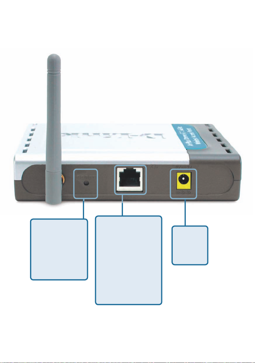
Connections
Pressing the
Reset Button
restores the
DWL-2100AP
to its original
factory default
settings.
The LAN Port is
Auto-MDI/MDIX.
You can insert
either a straightthrough or a
crossover Ethernet
cable in this port in
order to connect the
DWL-2100AP to the
local network.
5
Receptor
for the
Power
Adapter.
Page 6
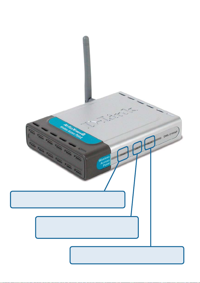
LEDs
LED stands for Light-Emitting Diode. The DWL-2100AP Wireless Access Point has 3
LEDs as shown below:
Power: Solid green light indicates connection.
Blinking green light indicates activ-
LAN:
ity on the Ethernet Port; solid green
light indicates connection.
WLAN: Blinking green light indicates wireless
activity; solid green light indicates connection.
6
Page 7

Features
5 Different Operation modes - Capable of operating in one of ve different
operation modes to meet your wireless networking requirements: Access Point,
AP-to-multipoint bridge with AP function, AP-to-Multipoint Bridging without AP
function , Repeater, or Wireless Client.
Faster wireless networking with the 802.11g standard to provide a wireless
data rate of up to 54Mbps (108Mbps in Super G mode).
Compatible with the 802.11b standard to provide a wireless data rate of up
to 11Mbps - that means you can migrate your system to the 802.11g standard
on your own schedule without sacricing connectivity.
Better security with WPA. The DWL-2100AP can securely connect to wireless
clients on the network using WPA (Wi-Fi Protected Access) providing a much
higher level of security for your data and communications than has previously
been available. AES is also supported by the DWL-2100AP to maximize the
network security with data encryption.
AP Manager Setup Wizard -The new Setup Wizard makes networks con-
guration quick and simple.
SNMP for Management - The DWL-2100AP is not just fast but it also
supports SNMP v.3 for a better network management. Superior wireless
AP manager software is bundled with the DWL-2100AP for network
conguration and rmware upgrade. Systems administrators can also setup
the DWL-2100AP easily with the Web-based conguration. A D-Link D-
View module will be downloadable for network administration and real-time
network trafc monitoring with D-Link D-View software.
Utilizes OFDM technology (Orthogonal Frequency Division Multiplexing).
Operates in the 2.4GHz frequency range.
Web-based interface for managing and conguring.
7
Page 8

Wireless Basics
D-Link wireless products are based on industry standards to provide easy-to-use and
compatible high-speed wireless connectivity within your home, business or public
access wireless networks. D-Link wireless products will allow you access to the data
you want, when and where you want it. You will be able to enjoy the freedom that
wireless networking brings.
A Wireless Local Area Network (WLAN) is a computer network that transmits and
receives data with radio signals instead of wires. WLANs are used increasingly in both
home and ofce environments, and public areas such as airports, coffee shops and
universities. Innovative ways to utilize WLAN technology are helping people to work
and communicate more efciently. Increased mobility and the absence of cabling and
other xed infrastructure have proven to be benecial for many users.
Wireless users can use the same applications they use on a wired network. Wireless
adapter cards used on laptop and desktop systems support the same protocols as
Ethernet adapter cards.
People use WLAN technology for many different purposes:
Mobility
within the operating range of the WLAN. Management decisions based on real-time
information can signicantly improve worker efciency.
- Productivity increases when people have access to data in any location
Low Implementation Costs - WLANs are easy to set up, manage, change
and relocate. Networks that frequently change can benet from WLANs ease of
implementation. WLANs can operate in locations where installation of wiring may be
impractical.
Installation and Network Expansion - Installing a WLAN system can be fast and
easy and can eliminate the need to pull cable through walls and ceilings. Wireless
technology allows the network to go where wires cannot go - even outside the home
or ofce.
Inexpensive Solution - Wireless network devices are as competitively priced as
conventional Ethernet network devices.
Scalability - WLANs can be congured in a variety of ways to meet the needs of
specic applications and installations. Congurations are easily changed and range
from Peer-to-Peer networks suitable for a small number of users to larger Infrastructure
networks to accommodate hundreds or thousands of users, depending on the number
of wireless devices deployed.
8
Page 9

Wireless Basics (continued)
The DWL-2100AP is compatible, in default mode, with the following wireless products:
D-Link AirPlus Xtreme GTM DWL-G650
Wireless Cardbus Adapters used with laptop computers
D-Link AirPlus XtremeTM G DWL-G520
Wireless PCI cards used with desktop computers
The DWL-2100AP is also interoperable with other 802.11g and 802.11b
standards-compliant devices.
Standards-Based Technology
The DWL-2100AP Wireless Access Point utilizes the 802.11b and the 802.11g
standards.
The IEEE 802.11g standard is an extension of the 802.11b standard. It increases the
data rate up to 54 Mbps (108Mbps in Super G mode) within the 2.4GHz band, utilizing
OFDM technology.
This means that in most environments, within the specied range of this device, you
will be able to transfer large les quickly or even watch a movie in MPEG format over
your network without noticeable delays. This technology works by transmitting high-
speed digital data over a radio wave utilizing OFDM (Orthogonal Frequency Division
Multiplexing) technology. OFDM works by splitting the radio signal into multiple smaller
sub-signals that are then transmitted simultaneously at different frequencies to the
receiver. OFDM reduces the amount of crosstalk (interference) in signal transmissions.
The D-Link DWL-2100AP will automatically sense the best possible connection speed
to ensure the greatest speed and range possible.
802.11g offers the most advanced network security features available today, including:
WPA , TKIP, AES and Pre-Shared Key mode.
9
Page 10

Wireless Basics (continued)
Installation Considerations
The D-Link AirPlus Xtreme G
wireless connection, from virtually anywhere within its operating range. Keep in mind,
however, that the number, thickness and location of walls, ceilings, or other objects
that the wireless signals must pass through, may limit the range. Typical ranges vary
depending on the types of materials and background RF (radio frequency) noise in
your home or business. The key to maximizing wireless range is to follow these basic
guidelines:
Keep the number of walls and ceilings between the DWL-2100AP and other network
1
devices to a minimum - each wall or ceiling can reduce your DWL-2100AP’s range
from 3-90 feet (1-30 meters.) Position your devices so that the number of walls or
ceilings is minimized.
Be aware of the direct line between network devices. A wall that is 1.5 feet thick
2
(.5 meters), at a 45-degree angle appears to be almost 3 feet (1 meter) thick. At a
2-degree angle it looks over 42 feet (14 meters) thick! Position devices so that the
signal will travel straight through a wall or ceiling (instead of at an angle) for better
reception.
Building materials can impede the wireless signal - a solid metal door or aluminum
3
studs may have a negative effect on range. Try to position wireless devices and
computers with wireless adapters so that the signal passes through drywall or open
doorways and not other materials.
Keep your product away (at least 3-6 feet or 1-2 meters) from electrical devices or
4
appliances that generate RF noise.
TM
DWL-2100AP lets you access your network, using a
10
Page 11

Getting Started
On the following pages we will show you an example of an Infrastructure Network
incorporating the DWL-2100AP.
An Infrastructure network contains an access point or a wireless router. The
Infrastructure Network example shown on the following page contains the following
D-Link network devices (your existing network may be comprised of other devices):
A wireless access point -
D-Link AirPlus Xtreme G
A wireless router - D-Link AirPlus Xtreme GTM DI-624
A laptop computer with a wireless adapter -
D-Link AirPlus Xtreme
A desktop computer with a wireless adapter -
D-Link AirPlus Xtreme GTM DWL-G520
A cable modem - D-Link DCM-201
TM
DWL-2100AP
TM
G DWL-G650
11
Page 12
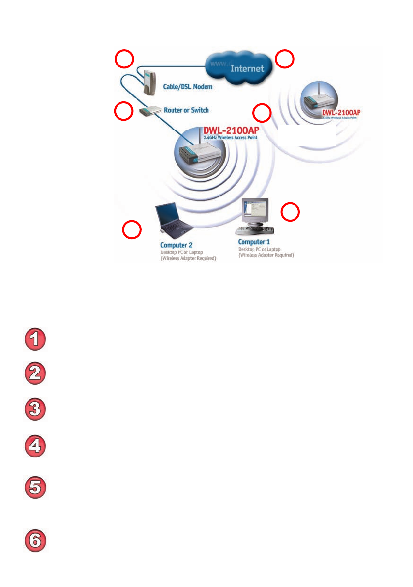
Getting Started (continued)
1
4
Setting up
a Wireless
Infrastructure
Network
2
3
5
6
Please remember that D-Link AirPlus XtremeTM G wireless devices are pre-congured
to connect together, right out of the box, with their default settings.
For a typical wireless setup at home (as shown above), please do the
following:
You will need broadband Internet access (a Cable or DSL-subscriber line into
your home or ofce).
Consult with your Cable or DSL provider for proper installation of the modem.
Connect the Cable or DSL modem to the DI-624 Router (see the printed
Quick Installation Guide included with your router.)
Connect the Ethernet Broadband Router to the DWL-2100AP (See the printed
Quick Installation Guide included with the DWL-2100AP.)
If you are connecting a desktop computer to your network, install the D-Link
AirPlus XtremeTM G DWL-G520 wireless PCI adapter into an available PCI
slot on your desktop computer.
(See the printed Quick Installation Guide included with the network adapter.)
Install the drivers for the D-Link DWL-G650 wireless Cardbus adapter into a
laptop computer.
(See the printed Quick Installation Guide included with the DWL-G650.)
12
Page 13
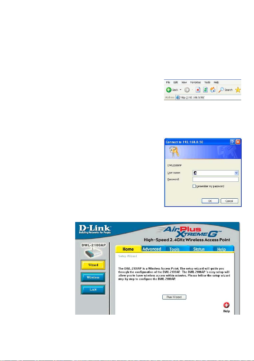
Using the Conguration Menu
After you have completed the Setup Wizard (please see the Quick Installation Guide that
came with the product) you can access the Conguration menu at any time by opening
the Web browser and typing in the IP address of the DWL-2100AP. The DWL-2100AP
default IP address is shown below:
Open the Web browser
Type in the IP address of the
DWL-2100AP
Note: if you have changed the default IP address assigned to the DWL-2100AP, make sure to
enter the correct IP address.
The Home>Wizard
screen will appear.
Please refer to the
Quick Installation
Guide for more infor-
mation regarding the
Setup Wizard.
Type admin in the User Name eld
Leave the Password blank.
(However, if you have changed the
password, please enter the correct
password.)
Click OK
admin
Home > Wizard
13
Page 14
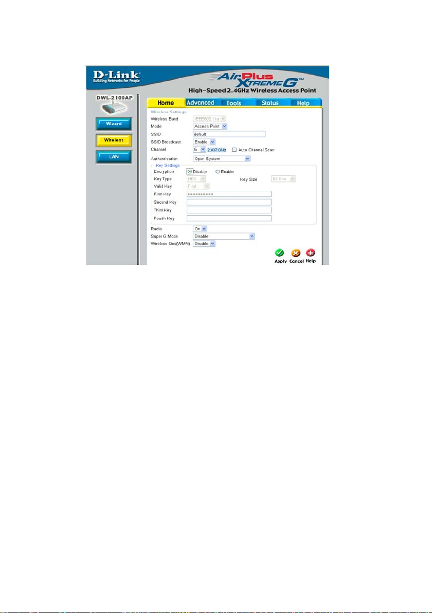
Using the Conguration Menu (continued)
Home > Wireless > AP Mode
Wireless
Band-
Mode- Access Point is selected from the pull down menu..
SSID-
SSID Broadcast-
Channel- 6 is the default channel. All devices on the network must share the same
Auto Channel
Scan-
Radio- Select On or Off.
Super G Mode-
IEEE 802.11g.
Service Set Identier(SSID)is the name designated for a specic wireless local area network(WLAN).The SSID factpru default setting is default.The SSID can be easily changed to connect to an existing network
or to establish a new wireless network.
Enable or Disable SSID Broadcast. Enabling this feature broadcasts the
SSID across the network.
channel.
Select Enable or Disable.(Enable this feature to auto-select the channel
for best wireless performance.)
Super G is a group of performance enhancement features that
increase end user application throughput in an 802.11g network.
Super G is backward compatible to standard 802.11g devices.
For top performance, all wireless devices on the network should be Super
G capable. Select either Disabled, Super G without Turbo, or Super G
with Dynamic Turbo.
14
Page 15

Using the Conguration Menu (continued)
Home > Wireless> AP Mode(continued)
Disabled: Standard 802.11g support, no enhanced capabilities.
Super G without Turbo: Capable of Packet Bursting, Fast Frames,
Compression, and no Turbo mode.
Super G with Dynamic Turbo: Capable of Packet Bursting, Fast Frames,
Compression, and Dynamic Turbo mode.This setting is backwards
compatible with non-Turbo (legacy) devices. Dynamic Turbo mode is
only enabled when all devices on the wireless network are congured
with Super G with Dynamic Turbo enabled.
WMM- Select Enable or Disable, Disable is selected by default. WMM stands
Authentication:
for Wi-Fi Multimedia, by enabling this feature it will improve the user
experience for audio and video applications over a Wi-Fi network.
Open System
Shared Key
Open System/Shared Key
WPA-EAP
WPA-PSK
WPA2-EAP
WPA2-PSK
WPA-Auto-EAP
WPA-Auto-PSK
Select Open System to communicate the key across the network.
Select Shared Key to limit communication to only those devices that share the same
WEP settings.
Select Open System/Shared Key to allow either form of data encryption.
Select WPA-EAP, WPA2-EAP, WP A-Auto-EAP to secure your network with the inclusion
of a RADIUS server.
Select WPA-PSK, WPA2-PSK, WPA-Auto-PSK to secure your network using a
password and dynamic key changes. (No RADIUS server required).
Home > Wireless>AP Mode>WEP Encryption
Encryption:
Key Type*:
Key Size:
Valid Key:
First through
Fourth keys:
*Hexadecimal digits consist of the numbers 0-9 and the letters A-F
ASCII (American Standard Code for Information Interchange) is a code for
representing English letters as numbers from 0-127
Select Disabled or Enabled. (Disabled is selected here).
Select HEX or ASCII.
Select 64-, 128-, 152-bits.
Select the 1st through the 4th key to be the active key.
Input up to four keys for encryption. You will select one of these
keys in the valid key eld.
15
Page 16
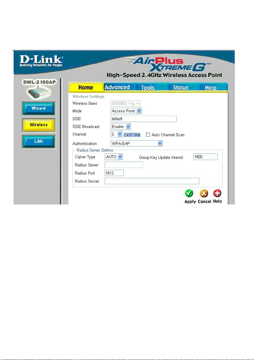
Using the Conguration Menu (continued)
Home>Wireless>AP Mode>WPA-EAP, WPA2-EAP, WPA-Auto-EAP
Cipher TypeGroup Key
Update Interval-
Radius ServerRadius PortRadius Secret-
Select AES, AUTO or TKIP from the pull down menu.
Select the interval during which the group key will be valid.
1800 is the recommended value. A lower interval may reduce data transfer
rate.
Enter the IP address of the Radius server.
Enter the Radius port.
Enter the the Radius secret.
16
Page 17
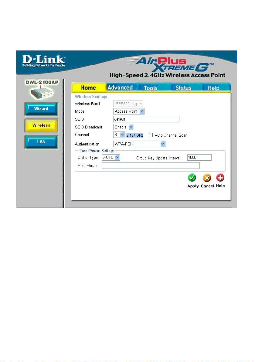
Using the Conguration Menu (continued)
Home>Wireless>AP Mode>WPA-PSK, WPA2-PSK, WPA-Auto-PSK
Cipher TypeGroup Key Up-
date IntervalPassPhrase-
Select AES, AUTO or TKIP from the pull down menu.
Select the interval during which the group key wll be valid. The default
value of 1800 is recommended.
Enter a PassPhrase in the corresponding eld.
17
Page 18
Using the Conguration Menu (continued)
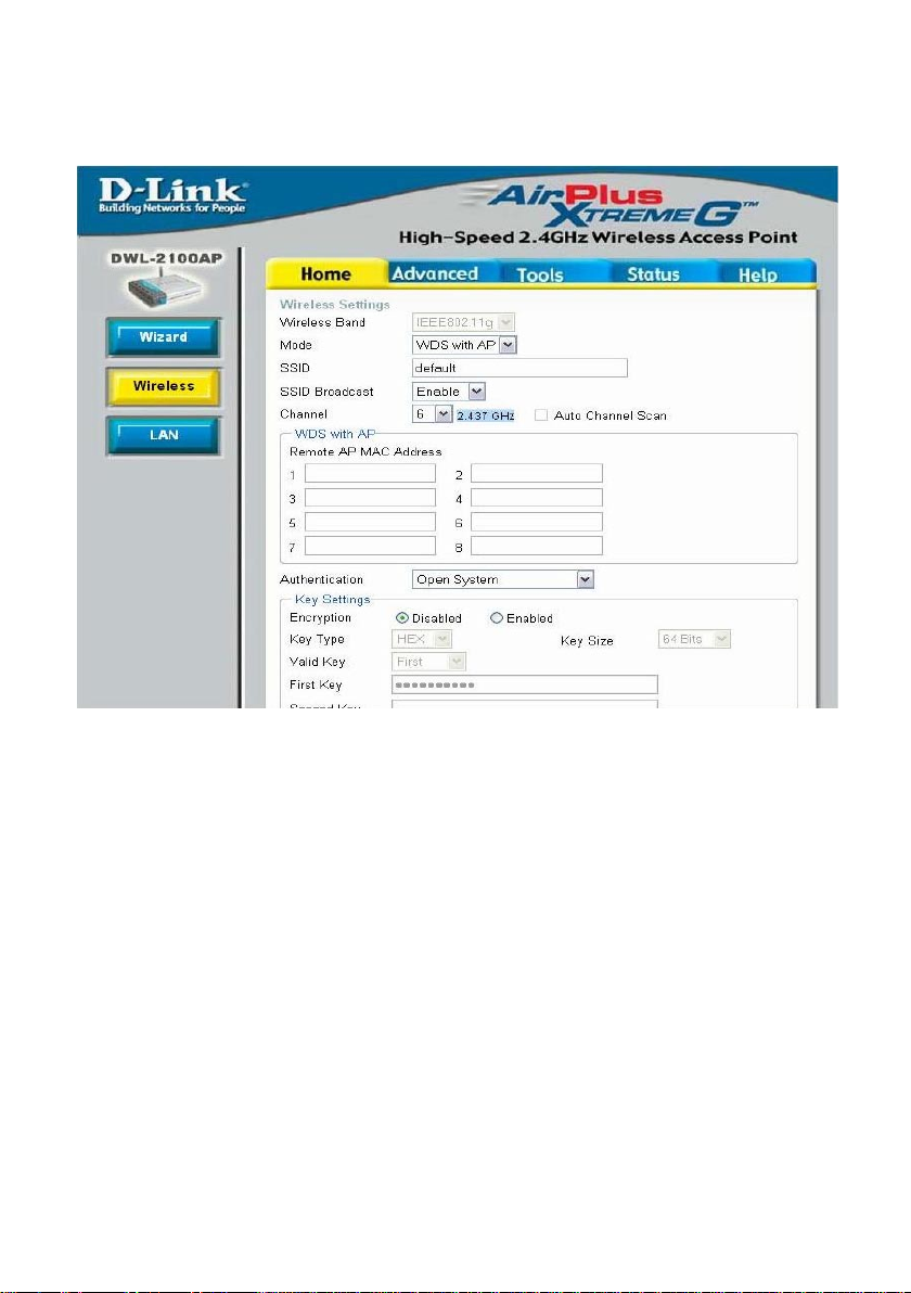
Home > Wireless > WDS with AP Mode
WDS (Wireless Distribution System) with AP mode can set APs to work
as PtP/PtMP Bridge and Access Point function simultaneously with the
same security setting. But all APs need to set as the same SSID.
Wireless
Band-
Mode-
SSID-
SSID Broadcast-
Channel- 6 is the default channel. All devices on the network must share the same
Auto Channel
Scan-
IEEE 802.11g.
WDS with AP mode is selected from the pull-down menu.
Service Set Identier(SSID)is the name designated for a specic wireless local area network(WLAN).The SSID factpru default setting is default.The SSID can be easily changed to connect to an existing network
or to establish a new wireless network.
Enable or Disable SSID Broadcast. Enabling this feature broadcasts the
SSID across the network.
channel.
Select Enable or Disable.(Enable this feature to auto-select the channel
for best wireless performance.)
18
Page 19

Using the Conguration Menu (continued)
Home > Wireless> WDS with AP Mode(continued)
Remote AP MAC
Address-
Enter the MAC address of the APs in your network that will serve
as bridges to wirelessly connect multiple networks.
Authentication
:
Open System
Shared Key
Open System/Shared Key
WPA-PSK
WPA2-PSK
WPA-Auto-PSK
Select Open System to communicate the key across the network.
Select Shared Key to limit communication to only those devices that share the same
WEP settings.
Select Open System/Shared Key to allow either form of data encryption.
Select WPA-PSK, WPA2-PSK, WPA-Auto-PSK to secure your network using a
password and dynamic key changes. (No RADIUS server required).
Home > Wireless> WDS with AP Mode> WEP Encryption
Encryption:
Key Type*:
Key Size:
Valid Key:
First through
Fourth keys:
*Hexadecimal digits consist of the numbers 0-9 and the letters A-F
ASCII (American Standard Code for Information Interchange) is a code for
representing English letters as numbers from 0-127
Select Disabled or Enabled. (Disabled is selected here).
Select HEX or ASCII.
Select 64-, 128-, 152-bits.
Select the 1st through the 4th key to be the active key.
Input up to four keys for encryption. You will select one of these
keys in the valid key eld.
Home > Wireless> WDS with AP Mode> WPA-PSK, WPA2-PSK,
WPA-Auto-PSK
Cipher
Type:
Group Key
Update Interval:
PassPhrase:
Select AES or AUTO from the pull down menu.
Select the interval during which the group key wll be valid. The
default value of 1800 is recommended.
Enter a PassPhrase in the corresponding eld.
19
Page 20
Using the Conguration Menu (continued)
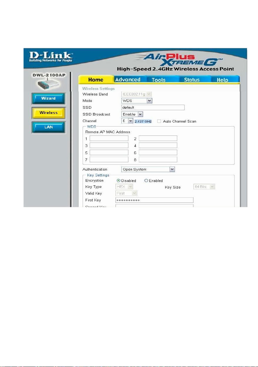
Home > Wireless >WDS Mode
WDS (Wireless Distribution System) mode can set APs to work as
PtP/PtMP Bridge. But all APs need to set as the same SSID.
Wireless
Band-
Mode WDS is selected from the pull-down menu.
SSID
SSID Broadcast-
Channel- 6 is the default channel. All devices on the network must share the same
Auto Channel
Scan
IEEE 802.11g.
Service Set Identier(SSID)is the name designated for a specic wireless local area network(WLAN).The SSID factpru default setting is default.The SSID can be easily changed to connect to an existing network
or to establish a new wireless network.
Enable or Disable SSID Broadcast. Enabling this feature broadcasts the
SSID across the network.
channel.
Select Enable or Disable.(Enable this feature to auto-select the channel for
best wireless performance.)
20
Page 21

Using the Conguration Menu (continued)
Home > Wireless>WDS Mode(continued)
Remote AP Mac
Address-
Authentication
Enter the MAC address of the APs in your network that will serve as
bridges to wirelessly connect multiple networks.
:
Open System
Shared Key
Open System/Shared Key
WPA-PSK
WPA2-PSK
WPA-Auto-PSK
Select Open System to communicate the key across the network.
Select Shared Key to limit communication to only those devices that share the same
WEP settings.
Select Open System/Shared Key to allow either form of data encryption.
Select WPA-PSK, WPA2-PSK, WPA-Auto-PSK to secure your network using a
password and dynamic key changes. (No RADIUS server required).
Home > Wireless> WDS Mode> WEP Encryption
Encryption:
Key Type*:
Key Size:
Valid Key:
First through
Fourth keys:
*Hexadecimal digits consist of the numbers 0-9 and the letters A-F
Select Disabled or Enabled. (Disabled is selected here).
Select HEX or ASCII.
Select 64-, 128-, 152-bits.
Select the 1st through the 4th key to be the active key.
Input up to four keys for encryption. You will select one of these
keys in the valid key eld.
ASCII (American Standard Code for Information Interchange) is a code for
representing English letters as numbers from 0-127
Home>Wireless>WDS Mode>WPA-PSK, WPA2-PSK, WPA-Auto-PSK
Cipher
Type:
Group Key
Update Interval:
PassPhrase:
AES is used here.
Select the interval during which the group key wll be valid. The
default value of 1800 is recommended.
Enter a PassPhrase in the corresponding eld.
21
Page 22
Using the Conguration Menu (continued)
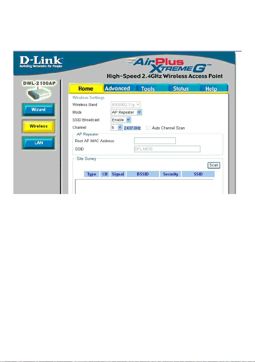
Home > Wireless > AP Repeater Mode
AP Repeater mode only can work with DWL-2100AP in the same H/W &
F/W version.
Wireless
Band-
Mode
Remote AP Mac
Address or
Site Survey-
IEEE 802.11g.
AP Repeater is selected from the pull-down menu.
Enter the MAC address of the root AP or site survey to choose the root
AP in your network that will allow you to repeat the wireless signal of the
root AP.
22
Page 23

Using the Conguration Menu (continued)
Home > Wireless>AP Repeater Mode(continued)
Authentication
:
Open System
Shared Key
Select Open System to communicate the key across the network.
Select Shared Key to limit communication to only those devices that share the same
WEP settings.
Home > Wireless> AP Repeater Mode> WEP Encryption
Encryption:
Key Type*:
Key Size:
Valid Key:
First through
Fourth keys:
*Hexadecimal digits consist of the numbers 0-9 and the letters A-F
ASCII (American Standard Code for Information Interchange) is a code for
representing English letters as numbers from 0-127
Select Disabled or Enabled. (Disabled is selected here).
Select HEX or ASCII.
Select 64-, 128-, 152-bits.
Select the 1st through the 4th key to be the active key.
Input up to four keys for encryption. You will select one of these
keys in the valid key eld.
23
Page 24
Using the Conguration Menu (continued)
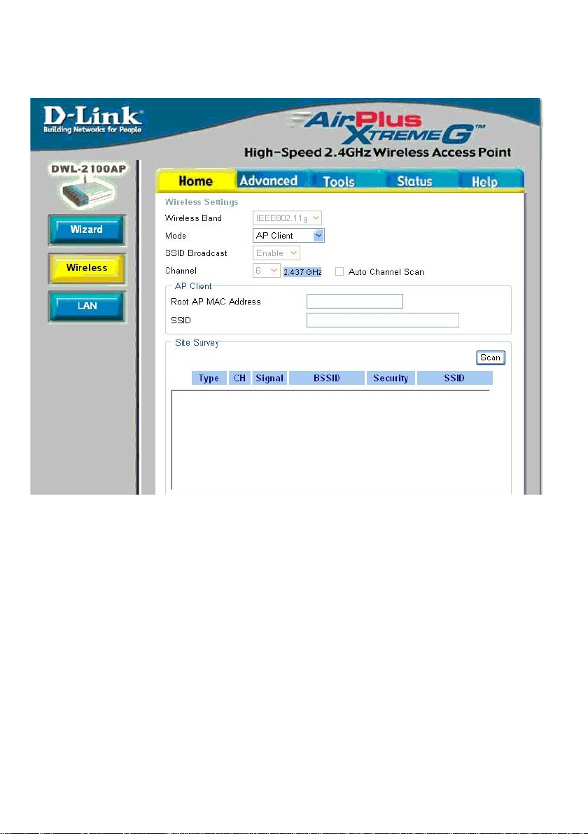
Home > Wireless > AP Client Mode
AP Client mode can only support single wired station for best
compatibility.
Wireless
BandModeRemote AP
Site Survey-
IEEE 802.11g.
AP Client is selected from the pull-down menu.
Will transform any IEEE 802.3 device(e.g., a computer, printer, etc.).
into an 802.11b wireless client when it communicates with another
DWL-2100AP that is acting as the root AP. Site survey to choose the
root AP in your network.
24
Page 25

Using the Conguration Menu (continued)
Home > Wireless>AP Client Mode(continued)
Authentication
:
Open System
Shared Key
WPA-PSK
WPA2-PSK
Select Open System to communicate the key across the network.
Select Shared Key to limit communication to only those devices that share the same
WEP settings.
Select WPA-PSK, WPA2-PSK to secure your network using a password and
dynamic key changes. (No RADIUS server required).
Home > Wireless> AP Client Mode> WEP Encryption
Encryption:
Key Type*:
Key Size:
Valid Key:
First through
Fourth keys:
*Hexadecimal digits consist of the numbers 0-9 and the letters A-F
ASCII (American Standard Code for Information Interchange) is a code for
representing English letters as numbers from 0-127
Select Disabled or Enabled. (Disabled is selected here).
Select HEX or ASCII.
Select 64-, 128-, 152-bits.
Select the 1st through the 4th key to be the active key.
Input up to four keys for encryption. You will select one of these
keys in the valid key eld.
Home> Wireless> AP Client Mode> WPA-PSK, WPA2-PSK
Cipher
Type:
Group Key
Update Interval:
PassPhrase:
Select AES or TKIP from the pull down menu.
Select the interval during which the group key wll be valid. The
default value of 1800 is recommended.
Enter a PassPhrase in the corresponding eld.
25
Page 26
Using the Conguration Menu (continued)
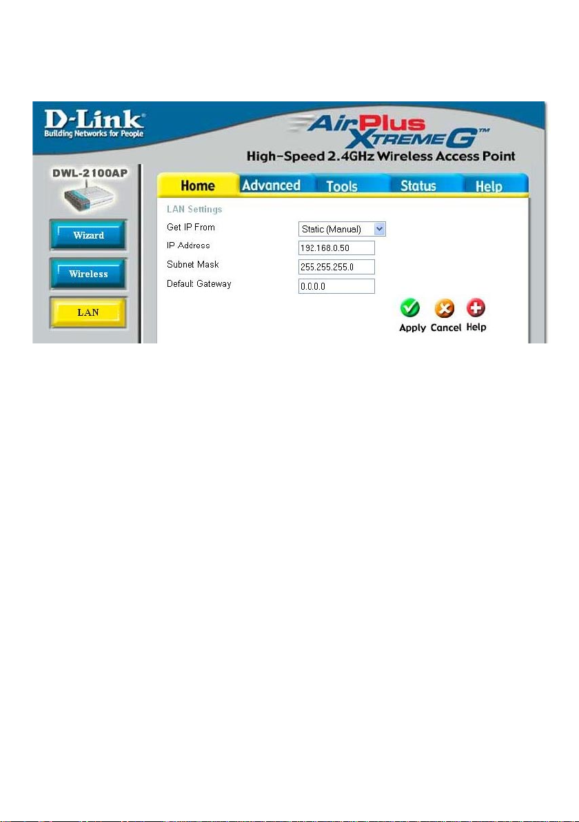
Home > LAN
LAN is short for Local Area Network. This is considered your internal network. These
are the IP settings of the LAN interface for the DWL-2100AP. These settings may be
referred to as private settings. You may change the LAN IP address if needed. The LAN
IP address is private to your internal network and cannot be seen on the Internet.
Get IP From-
IP Address- The IP address of the LAN interface. The default IP address is:
Subnet Mask- The subnet mask of the LAN interface.
Default Gateway- This eld is optional. Enter in the lP address of the gateway on
Apply-
Select Static (Manual) or Dynamic (DHCP) as the method you
will use to assign an IP address to the DWL-2100AP.
192.168.0.50
The default subnet mask is 255.255.255.0
your network.
Click Apply to save the changes.
26
Page 27
Using the Conguration Menu (continued)
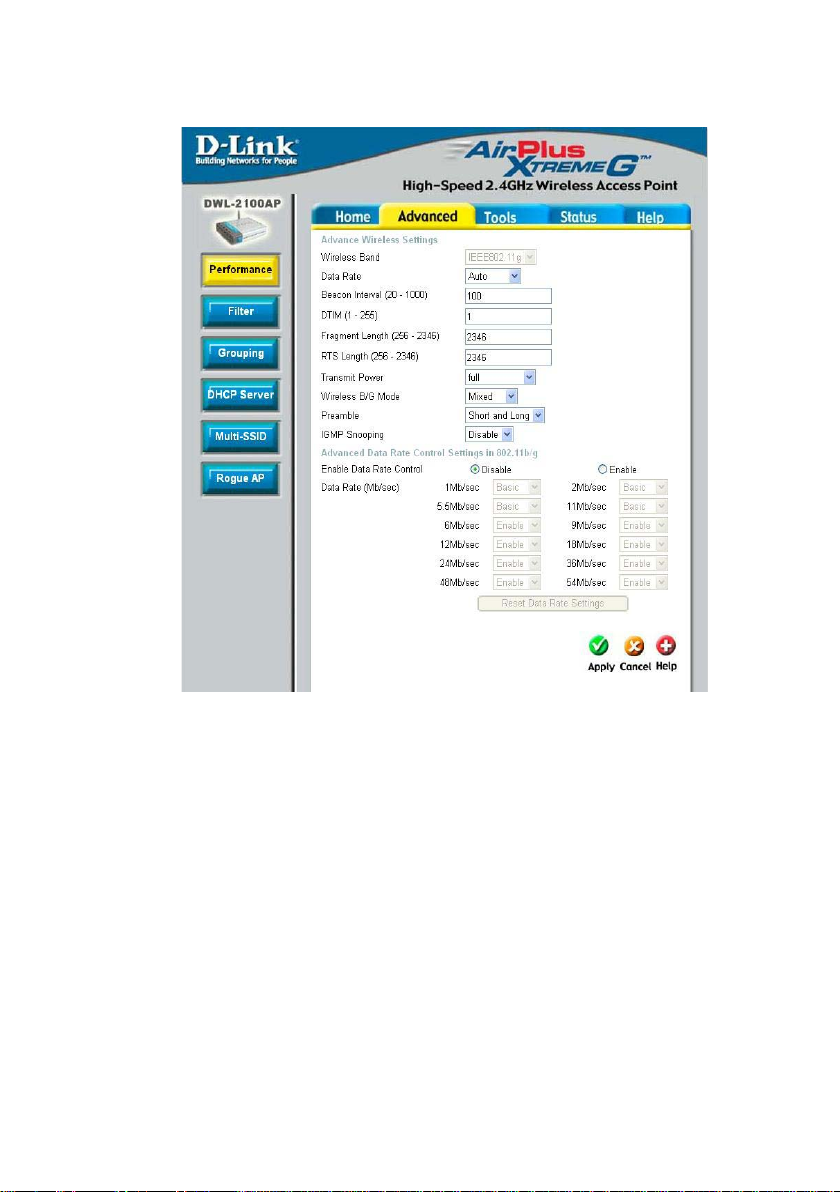
Advanced > Performance
Wireless BandData Rate-
Beacon Interval-
DTIM-
Fragment Length-
RTS Length-
Transmit Power-
IEEE 802.11g
The Data Rates are Auto, 1Mbps, 2Mbps, 5.5Mbps, 6Mbps, 9Mbps,
11Mbps, 12Mbps, 18Mbps, 24Mbps, 36Mbps, 48Mbps, 54Mbps.
Beacons are packets sent by an access point to synchronize a network.
Specify a beacon interval value. The default (100) is recommended.
(Delivery Trafc Indication Message)- 3 is the default setting. DTIM
is a countdown informing clients of the next window for listening to
broadcast and multicast messages.
The fragmentation threshold, which is specied in bytes, determines
whether packets will be fragmented. Packets exceeding the 2346 byte set-
ting will be fragmented before transmission. 2346 is the default setting.
This value should remain at its default setting of 2,346. If you encoun-
ter inconsistent data ow, only minor modications to the value range
between 256 and 2,346 are recommended.
Choose full, half (-3dB), quarter (-6dB), eighth (-9dB), minimum
power.
27
Page 28

Wireless B/G
Mode-
This function allows you to congure the wireless network with IEEE
802.11g only, IEEE 802.11b only, or IEEE 802.11g with backward in-
teroperability with IEEE 802.11b.
PreambleAntenna Diversity
(continued)-
IGMP Snooping:
Advanced Data
Rate Settings-
Select the default value Short and Long, or Long Only.
Diversity: The DWL-2100AP will auto switch to the antenna with better
RSSI value.
Left Antenna: The AP will not switch antenna and the radio will use the
left antenna (when facing the AP) to transmit and receive packets.
Right Antenna: AP won’t switch antenna and the radio will use the right
antenna (when facing the AP) to transmit and receive packets.
Internet Group Management Protocol (IGMP) snooping allows the AP
to recognize IGMP queries and reports sent between routers and an
IGMP host (wireless STA). When enabled IGMP snooping, the AP will
forward multicast packets to IGMP host based on IGMP messages
passing through the AP.
Specify the data rates at which the DWL-2100AP should transmit signals.
For 802.11b, choose from 5.5Mbps, 11Mbps. For 802.11g, choose from
9Mbps, 18Mbps, 36Mbps, 48Mbps, 54Mbps. For 802.11b/g, choose
from 6Mbps, 9Mbps, 12Mbps, 18Mbps, 24Mbps, 36Mbps, 48Mbps,
54Mbps.
28
Page 29

Using the Conguration Menu (continued)
Advanced > Filters > Wireless Access Settings
The following elds are available for conguration in this window:
IEEE 802.11g.Wireless Band-
Access Control- Select Disabled to disable the lters function.
MAC Address- Enter the MAC addresses of the devices that you wish to control
Ac ces s Co ntr ol
List-
Select Accept to accept only those devices with MAC addresses in
the Access Control List.
Select Reject to reject the devices with MAC addresses in the Access
Control List.
here. Click Save to add to the Access Control List.
The MAC addresses in this list can be accepted or rejected for
inclusion in the network, depending upon the Access Control selec-
tion. Click on the Delete icon next to the MAC address to delete
it from the list.
Click Apply to save the changesApply-
29
Page 30

Using the Conguration Menu (continued)
Advanced > Filters > WLAN Partition
Wireless Band-
Internal Station
Connection-
Ethernet to
WLAN Access-
IEEE 802.11g
Enabling this feature allows wireless clients to communicate
with each other. If this feature is disabled, wireless stations of
the selected band are not allowed to exchange data through the
access point.
Enabling this feature allows Ethernet devices to communicate with
wireless clients. If this feature is disabled, all data from the Ethernet
to associated wireless devices is blocked, but wireless devices can
still send data to the Ethernet.
30
Page 31

Using the Conguration Menu (continued)
Advanced > Grouping
The D-Link DWL-2100AP allows you to balance the distribution of wireless client
connections across multiple access points. Using load balancing, you can prevent
scenarios where a single access point in your network shows performance
degradation because it is handling a disproportionate share of the wireless trafc.
Load Balance-
User Limit-
Link Intergrate-
Eth ernet Link
Status-
Select Enabled or Disabled.
When Load Balance is enabled, select the user limit.
Select Enabled or Disabled
Displays the link status of the Ethernet connect.
31
Page 32

Using the Conguration Menu (continued)
DHCP Server
Control-
Enable or
Disable the DHCP
function here.
Dynamic Pool
Settings
IP Assigned
From-
Input the rst IP address available for
assignment in your
network.
The Range of Pool
(1-255)-
Enter the number of
IP addresses
available for
assignment.
SubMask-
Advanced > DHCP Server > Dynamic Pool Settings
Enter the subnet mask.
Gateway-
Wins-
DNS-
Domain NameLease Time (60-
31536000 sec)-
Status Apply-
Enter the IP address of the router on the network.
Windows Internet Naming Service is a system that determines the
IP address of a network computer that has a dynamically assigned IP
address.
Enter the IP address of the DNS server. The DNS server translates
domain names such as www.dlink.com into IP addresses.
Enter the Domain Name of the DWL-2100AP.
The Lease Time is the period of time before the DHCP server will
assign a new IP address.
Turn the Dynamic Pool Settings ON or OFF here.
Click Apply if you have made any changes.
32
Page 33

Using the Conguration Menu (continued)
Advanced > DHCP Server > Static Pool Settings*
DHCP Server
Control-
Enable or
Disable the DHCP
function here.
Static Pool
Settings
Assigned lP-
Enter the static IP
address of the
device here.
Assigned MAC
Address-
Enter the MAC
address of the
device here.
SubMask-
Enter the subnet
mask here.
Gateway-
Enter the IP address of the gateway on the network.
Wins-
Windows Internet Naming Service is a system that determines the IP address of the a
network computer that has a dynamically assigned IP address.
DNS-
Enter the IP address of the DNS server. The DNS server translates domain names such as
www.dlink.com into IP addresses.
Domain Name-
Enter the Domain Name of the DWL-2100AP.
Status-
Turn the Static Pool Settings ON or OFF here.
Assigned Static Pool
After you have input the Static Pool Settings for each device, click Apply and the
prole will appear in this list at the bottom of the window.
*Please note that IPs assigned in the Static Pool Settings must not be in the same
range as those in the Dynamic Pool Settings.
33
Page 34

Using the Conguration Menu (continued)
Advanced > DHCP Server > Current IP Mapping List
This screen displays information about the current DHCP dynamic and static IP address
pools. This information is available when you enable the DHCP function of the DWL-2100AP
and assign dynamic and static IP address pools.
Current DHCP
Dynamic Pools-
Binding MAC
address-
Assigned IP
address-
Lease TimeCurrent DHCP
Static PoolsBinding MAC
addressAssigned IP
address-
These are IP address pools to which the DHCP server function has
assigned dynamic IP addresses.
The MAC address of a device on the network that is within the DHCP
dynamic IP address pool.
The current corresponding DHCP-assigned dynamic IP address
of the device.
The length of time that the dynamic IP address will be valid.
These are IP address pools to which the DHCP server function has
assigned static IP addresses.
The MAC address of a device on the network that is within the DHCP
static IP address pool.
The current corresponding DHCP-assigned static IP address of
the device.
34
Page 35

Using the Conguration Menu (continued)
Advanced > Multi-SSID
If you want to congure the Guest and Internal networks on Virtual LAN (VLANs), the
switch and DHCP server you are using must suppport VLANs. As a prerequisite step,
congure a port on the switch for handling VLAN tagged packets as described in the
IEEE802.1Q standard.
35
Page 36

Using the Conguration Menu (continued)
Advanced > Multi-SSID(continued)
Index- The Primary SSID and Security cannot be changed here.Those values
SSID- When you Enable Multi-SSID you can name each Multi-SSID.
follow the setting in Home>Wireless.
Security-
VLAN
Group ID-
The Security option for these seven Multi-SSIDs are
None, Open System or Shared Key, WPA-EAP, WPA-PSK,
WP A2-EAP, WPA2-PSK, WPA-Auto-EAP, WPA-Auto-PSK
When you Enable VLAN State and congure internal and Multi-SSID net-
works on VLANs, this eld will be enable.
Provide a number between 1 and 4094 for internal VLAN.
This will cuase the access point to send DHCP request woth the VLAN tags.
The switch and the DHCP server must support VLAN IEEE802.1Q frames.
The access point must be able to reach the DHCP Server .
Check with the Administator greading the VLAN and DHCP congurations
Advanced > Multi-SSID > WEP Encryption
Key TypeKey Size-
Key-
Select HEX or ASCII
Select 64-,128-,152-bits
Select the 1st through the 4th key to b the active key. Enter key here.
Advanced > Multi-SSID > WPA-PSK, WPA2-PSK, WPA-Auto-PSK
Cipher
Type:
Select AES, AUTO or TKIP from the pull down menu.
Group Key
Update Interval:
PassPhrase:
Note: If any of the SSID uses security of WPA-PSK, WPA2-PSK, WPA-Auto-PSK,
WPA-EAP, WPA2-EAP, WPA-Auto-EAP, it will occupy the key space 2 and 3, leaves
only key 1 and key 4 for other SSIDs to use for WEP key.
The Multi-SSID’s security can be WPA-EAP, WPA2-EAP, or WPA-Auto-EAP only when
the Primary SSID’s security is at the same security level. Also, they must connect to the
same RADIUS server.
Select the interval during which the group key wll be valid. The
default value of 1800 is recommended.
Enter a PassPhrase in the corresponding eld.
36
Page 37

Using the Conguration Menu (continued)
Advanced > Rogue AP
BSS Type-
Band-
Security-
Rogue AP List-
AP ListRogue AP Pro-
tection-
The Basic Service Set Type allows you to select from AP BSS, Ad Hoc, or
Both.
Select the type of network (bands 11b and 11g) that you would like the AP
detection to search on.
Select the Security type OFF, WEP, WPA-Enterprise, WPA-Personal,
WP A2-Enterprise, WPA2-Personal, WPA-Auto-Enterprise, and WP A-
Auto-Personal that you would like to consider during AP detection.
This window shows all of the neighbor APs detected, which is based on
your criteria from above (BSS Type, Band, and Security). If the AP is in
the same network, or if you know the AP, just click on “Add” to save it to
the AP list.
This window shows all of the APs that are allowed access on the network.
Enable this function to keep the connection with the authorized clients
even though there are rogue APs around.
37
Page 38

Using the Conguration Menu (continued)
Tools > Admin
Administrator AP
with WLAN-
Limit Administrator
VLAN ID-
Limit Administrator
IP-
IP Range-
User NameOld PasswordNew Password-
Conrm New
PasswordConsole
Protocol-
Check to enable the administrator can manage AP from WLAN.
Check the box provided and enters the specic VLAN ID that the
administrator will be allowed to log in from.
Check to enable the Limit Administrator IP address.
Enter the IP address range that the administrator will be allowed to
log in from and then click the Add button.
Enter a user name; admin is the default setting.
To change your password, enter your old password here.
Enter your new password here.
Enter your new password again.
Choose None, Telnet or SSH.
38
Page 39

Time Out-
Select a time period after which a session timeout will occur.
Community
String-
Trap Sever IP-
Enter the Public/Private Community string as the password to
access the SNMP service.
Enter the trap server IP when you enable User status notication.
39
Page 40

Using the Conguration Menu (continued)
Tools > System
Apply Settings and
Restart-
Click Restart to ap-
ply the system settings and restart the
DWL-2100AP.
Restore to
Factory Default Settings-
Click Restore to
return the
DWL-2100AP to its
factory default
settings.
Tools > Firmware
Update File-
After you have downloaded the most
recent version of the
rmware from www.
support.dlink.com
you can browse
your hard drive to
locate the
downloaded le and
click OK to update
the rmware.
40
Page 41

Using the Conguration Menu (continued)
Tools > Cfg File
Update File-
Load Settings to
the Local Hard
Drive-
Browse for the conguration settings that you have saved to your hard
drive. Click OK when you made your selection.
Click OK to load the selected
settings.
41
Page 42

Using the Conguration Menu (continued)
Status > Device Info
This window displays the settings of the DWL-2100AP, as well as the Firmware version
and the MAC address.
42
Page 43

Using the Conguration Menu (continued)
Status > Stats
This window displays the statistics of the wireless local area network.
43
Page 44

Using the Conguration Menu (continued)
Status > Client Info
Client Information Select this option to obtine infomation on wireless clients.(A client is a
device on the network that is communicating with the DWL-2100AP)
44
Page 45

Using the Conguration Menu (continued)
Status > Log
The log information will include, but not limited to, the following items:
• Upgrade Firmware
• Client associate and disassociate with AP
• Web loginIf you require
Log Sever-
Log Server/IP
Address-
Log Type-
If you require more space to hold your logs, please provide the
IP address of the Server that will store your logs. The embedded
memory can only have up to 300 logs.
Enter the IP address of the log server.
Check the box for the type of activity you want to log. There are
three types: System Activity, Wireless Activity, and Notice.
45
Page 46

Using the Conguration Menu (continued)
Help
At this window you can access the help screens for the topics listed.
46
Page 47

Using the AP Manager
The AP Manager is a convenient tool to manage the conguration of your network
from a central computer. With AP Manager there is no need to congure devices
individually.
To launch the AP Manager:
• Go to the Start Menu
• Select Programs
• Select D-Link AirPlus Xtreme G
AP Manager
• Select DWL-2100AP
Discovering Devices
®
Click on this button to discover the
devices available on the network.
47
Page 48

Using the AP Manager (continued)
Selecting Devices
The AP Manager allows you to congure multiple devices all at once. To select a single
device, simply click on the device you want to select. To select multiple devices, hold
down the Ctrl key while clicking on each additional device. To select an entire list, hold
the Shift key, click on the rst AP on the list and then click on the last AP on the list.
IP Conguration
You can assign an IP address to an AP or assign IP
addresses to multiple AP’s by clicking on this button
after selecting the device(s).
Select the AP that you want to assign an IP address to and click the IP button. Enter
the IP address and IP netmask for the selected device and click OK.
You can congure multiple AP’s with IP addresses all at once. Click on the IP button
after you’ve selected all of the AP’s you want to assign an IP address. Enter the IP
address you want to assign the rst unit and the AP manager will automatically assign
sequential IP addresses.
48
Page 49

Using the AP Manager (continued)
Device Conguration
Click on this button to access the conguration
properties of the selected device(s).
The device conguration window allows you to congure settings but does not actually
apply the settings to the device unless you click the Apply button. You can also save
and load conguration les from this window. When you load a conguration le, you
must click Apply if you want the settings to be applied to the selected device(s).
The Check All button will select all congurable options. Any setting
that has a checkmark next to it is applied to the device or saved to
the conguration le.
The Clear Checks button deselects all congurable options. This
feature is useful if you only want to change a few settings. Deselect
all items and only check the items that you want to modify.
Refresh will revert to the actual device settings of the selected
device(s).
To save settings to the device, you must click the Apply button. Only
settings that have a checkmark next to them will be applied.
The open button is used to load a previously saved conguration le.
After opening a conguration le, you must click the Apply button to
save the settings to the selected device(s).
The save button allows you to save a conguration le of the selected
device settings. Only settings that have a checkmark next to them
are saved. You cannot save a conguration le if you selected more
than one device in the device list.
The Exit button will close the device conguration window. Any settings
that haven’t been applied will be lost.
49
Page 50

Using the AP Manager (continued)
Device Conguration>General
When selecting multiple devices for conguration, some options are unavailable for
conguration as noted(*) below:
• Device Name(*): This allows you to change the device name for the selected
access point. You must place a checkmark in the Device Name box to change
the name. This option can only be congured when one access point is selected for
conguration.
• IP address and Subnet Mask(*): If you’ve selected one device for conguration and
you want to change the IP address of the device, check the IP Address box. You can
then enter an IP address and Subnet Mask for the selected access point. This option
is only congurable when one access point is selected for conguration. To congure
multiple devices with an IP address at one time, please reference the previous page.
• Gateway: Enter the IP address of your gateway, typically your router address.
• DHCP client: There is a pulldown menu to select enabled or disabled. When
enabled, the selected device(s) will function as a DHCP client(s). This allows them to
receive IP conguration information from a DHCP server. When disabled, the access
point(s) must have a static IP address assigned to them.
50
Page 51

Using the AP Manager (continued)
Device Conguration>General (continued)
Telnet Support: This pulldown selection enables or disables the ability to Telnet
•
into the selected device(s).
Telnet Timeout: This pulldown selection denes the timeout period during a Telnet
•
session with the selected device(s).
51
Page 52

Using the AP Manager (continued)
Device
Conguration>Wireless
• SSID: The Service Set (network)
Identier of your wireless network.
• Channel: Allows you to select a
channel. 6 is the default setting.
• SSID Broadcast: Allows you to
enable or disable the broadcasting
of the SSID to network clients.
• Super G: Super G is a group of
performance enhancement features
that increase end user application
throughput in an 802.11g network.
Super G is backwards compatible
with standard 802.11g devices.
For ideal performance, all wireless
devices on the network should be
Super G capable. The modes are
listed below:
• Radio Wave: Enable or disable the wireless functionality of the selected device(s).
• Data Rate: A pulldown menu to select the maximum wireless signal rate for the
selected devices(s).
• Beacon Interval (20~1000): Beacons are packets sent by an access point to
synchronize a network. Specify the beacon value for the selected device(s) here.
The default value of 100 is recommended.
• DTIM (1~255): DTIM (Delivery Trafc Indication Message) is a countdown informing
clients of the next listening window for broadcast and multicast messages.
• Fragment Length (256~2346): This sets the fragmentation threshold (specied
in bytes). Packets exceeding the value set here will be fragmented. The default is
2346.
• RTS Length (256~2346): The RTS value should not be changed unless you encounter
inconsistent data ow. The default value is 2346.
• Tx Power: A pulldown menu for selecting the transmit power of the selected
device(s).
• Auto Channel Scan: Enable to scan for the least populated channel.
52
Page 53
Using the AP Manager (continued)
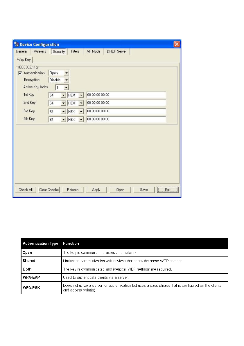
Device Conguration>Security
The Security tab contains the WEP conguration settings on the intial page. If you select
WPA as the authentication type, an additional tab will appear with the WPA conguration
options based on your selection.
• Authentication Type: Select from the pulldown menu the type of authentication to
be used on the selected device(s).
• Encryption: Enable or disable encryption on the selected device(s).
• Active Key Index: Select which dened key is active on the selected device(s).
• Key Values: Select the key size (64-bit, 128-bit, or 152-bit) and key type (HEX or
ASCII) and then enter a string to use as the key. The key length is automatically
adjusted based on the settings you choose.
53
Page 54

Using the AP Manager (continued)
Device Conguration>Security>WPA-EAP
• Cipher Type: Select auto, TKIP, or AES from the pulldown menu.
• Group Key Update Interval: Select the interval during which the group key will
be vaild. 1800 is the recommended setting. A lower interval may reduce transfer
rates.
• RADIUS Server: Enter the IP address of the RADIUS server.
• RADIUS Port: Enter the port used on the RADIUS server.
• RADIUS Secret: Enter the RADIUS secret.
54
Page 55

Using the AP Manager (continued)
Device Conguration>Security>WPA-PSK
• Cipher Type: Select auto, TKIP, or AES from the pulldown menu.
• Group Key Update Interval: Select the interval during which the group key will
be vaild. 1800 is the recommended setting. A lower interval may reduce transfer
rates.
• PassPhrase: Enter a PassPhrase between 8-63 characters in length .
55
Page 56

Using the AP Manager (continued)
Device Conguration>Filters
• Internal Station Connection: Enabling this allows wireless clients to communicate
with each other. When this option is disabled, wireless stations are not allowed to
exchange data through the access point.
• Ethernet to WLAN Access: Enabling this option allows Ethernet devices to
communicate with wireless clients. When this option is disabled, all data from
Ethernet to wireless clients is blocked. Wireless devices can still send data to the
Ethernet devices when this is disabled.
• Access Control: When disabled access control is not ltered based on the MAC
address. If Accept or Reject is selected, then a box appears for entering MAC
addresses. When Accept is selected, only devices with a MAC address in the list
are granted access. When Reject is selected, devices in the list of MAC addresses
are not granted access.
56
Page 57

Using the AP Manager (continued)
Device Conguration>AP Mode
• Access Point: The default setting used to create a wireless LAN.
• WDS with AP: Allows you to connect multiple wireless LANs together,while still functioning
as an AP.If enable, you must enter the MAC address of the other DWL-2100APs.
• WDS: Allows you to connect mulitple wireless LANs together. All other LANs must be
using DWL-2100APs.When enable , you must enterthe MAC address of the other
DWL-2100APs.
• AP Repeater: Allows you to repeat the wireless signal of the root access point. When
enabled you must enter the MAC address of the root access point.
• AP Client: Allows any device with an Ethernet connection to connect to the wireless
network via another DWL-2100AP, such as a printer, gaming console (Xbox, PS2), or
a computer. You will need to enter the SSID of the DWL-2100AP that is functioning as
an AP.
57
Page 58

Using the AP Manager (continued)
Device Conguration>DHCP
• DHCP Server: Enable or disable the DHCP server function.
• Dynamic Pool Settings: Click to enable Dynamic Pool Settings. Congure the IP
address pool in the elds below.
• Static Pool Settings: Click to enable Static Pool Settings. Use this function to assign the
same IP address to a device at every restart. The IP addresses assigned in the Static
Pool list must NOT be in the same IP range as the Dynamic Pool.
• IP Assigned From: Enter the initial IP address to be assigned by the DHCP server.
• Range of Pool (1~255): Enter the number of allocated IP addresses.
• SubMask: Enter the subnet mask.
• Gateway: Enter the gateway IP address, typically a router.
• Wins: Wins (Windows Internet Naming Service) is a system that determines the IP
address of a network computer with a dynamically assigned IP address, if applicable.
• DNS: The IP address of the DNS server, if applicable.
• Domain Name: Enter the domain name of the DWL-2100AP, if applicable.
• Lease Time: The period of time that the client will retain the assigned IP address.
• Status: This option turns the dynamic pool settings on or off.
58
Page 59

Using the AP Manager (continued)
Device Conguration>Client Info
Client Info.
Mac Address
Band
Authentication
RSSI
Power Mode
Select the option to obtain information on wireless clients.(A client is a
device on the network that is communicating with the DWL-2100AP)
Displays the MAC address of the client.
Displays the wireless band.
Displays the type of authentication that is enabled.
Indicates the strength of the signal.
Displays the status of the power saving feature.
59
Page 60

Using the AP Manager (continued)
Device Conguration>Multi-SSID
The DWL-2100AP offers congure using Multiple SSIDs. allowing of a vitually sepegated
station by sharing the same channel. One primary SSIDcan be assocaited with up to 3
guest SSIDs. Becuase guest SSIDs cannot be scanned by site survey tools uers cannnot
assocaite with guest SSIDs unless thy know the exact SSID and security setting. The
VLAN function can been enabled for both the primary SSID and the guest SSID.
60
Page 61

Using the AP Manager (continued)
Conguration Files
The DWL-2100AP allows you to save the device settings to a conguration le. To save
a conguration le, follow these steps:
• Select a device from the Device List on the main screen of the AP Manager.
• Click the device conguration button.
• Click the Save button after you have all of the settings as you want them.
• A popup window will appear prompting you for a le name and location. Enter the
le name, choose a le destination, and click Save.
Device Conguration button.
To load a previously saved conguration le, follow these steps:
• Select a device or devices from the Device List on the main screen of the AP
Manager.
• Click the device conguration button.
• Click the Open button.
• A popup window will appear prompting you to locate the conguration le. Locate the
le and click Open.
• The conguration le is loaded into the AP Manager but has not actually been written to
the device(s). If you want to use the newly loaded conguration for the selected device(s),
click Apply
and the conguration settings will be written to the device(s).
Device Conguration button.
You must alw ays clic k
Apply in the Conguration
window if you want the
settings to take effect.
61
Page 62

Using the AP Manager (continued)
Firmware
You can upgrade the rmware by clicking on
this button after selecting the device(s).
To upgrade the rmware:
• Download the latest rmware upgrade from http://support.dlink.com to an easy
to nd location on your hard drive.
• Click on the rmware button as shown above.
• A popup window will appear. Locate the rmware upgrade le and click Open.
IMPORTANT! DO NOT DISCONNECT POWER FROM THE UNIT WHILE THE
FIRMWARE IS BEING UPGRADED.
System Settings
You can customize the basic System Settings for
the DWL-2100AP by clicking on this button.
• Access Password: This sets the admin password for
the selected device(s).
• Auto Refresh: This setting allows you to enable auto
refreshing of the network device list. By default this option
is disabled. If you choose to enable it, you must enter the
refresh interval in seconds.
All other settings on this screen should
be left at the default setting.
62
Page 63

Using the AP Manager (continued)
Setup Wizard
This button will launch the Setup Wizard that will
guide you through device conguration.
Click Next
Enter a Password and retype it
in the Verify Password eld.
Click Next
63
Page 64

Using the AP Manager (continued)
Setup Wizard (continued)
Enter the SSID and the
Channel for the network.
Click Next
If you want to enable Encryp-
tion, enter the Encryption values
here.
Click Next
64
Page 65
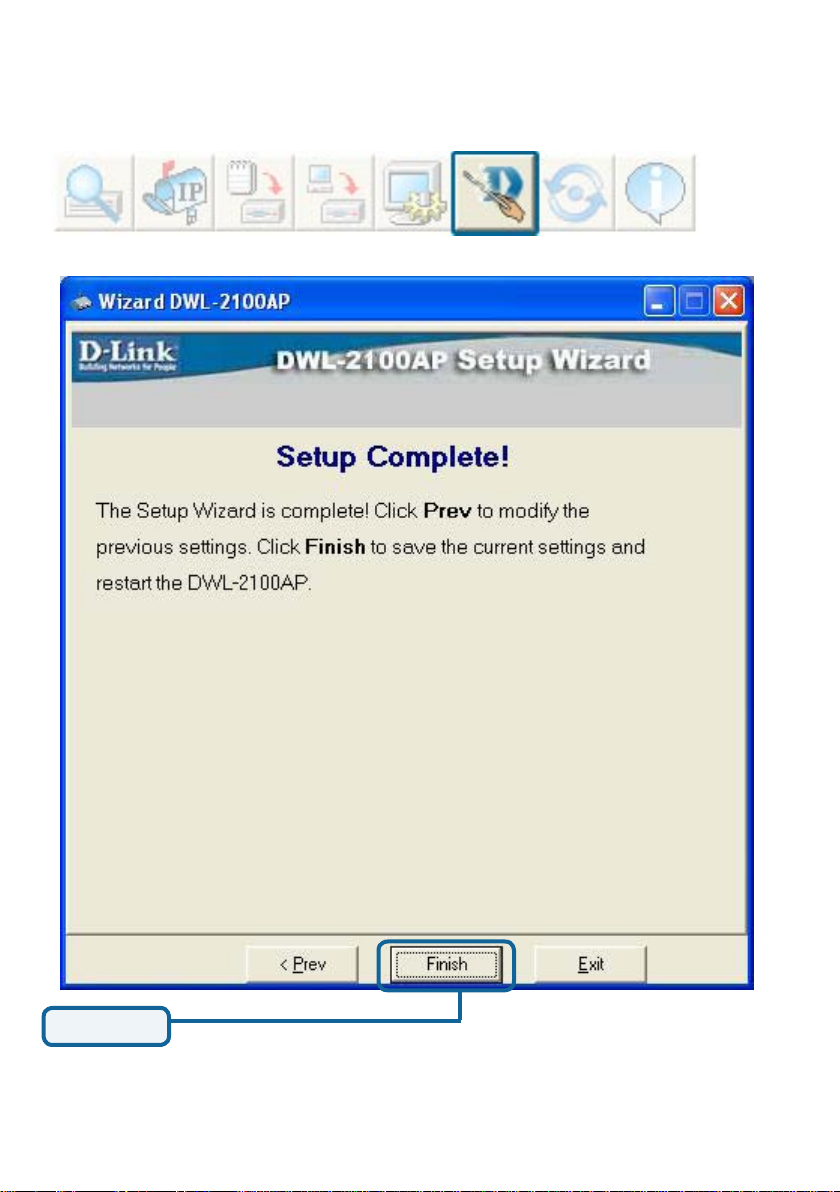
Using the AP Manager (continued)
Setup Wizard (continued)
Click Finish
The DWL-2100AP setup is complete!
65
Page 66

Using the AP Manager (continued)
Refresh
Click on this button to refresh the list
of devices available on the network.
Devices with a checkmark
next to them are still
available on the network.
Devices with an X are no
longer available on the
network.
About
Click on this button to view the version
of AP Manager.
66
Page 67

Networking Basics
Using the Network Setup Wizard in Windows XP
In this section you will learn how to establish a network at home or work, using
Microsoft Windows XP.
Note: Please refer to websites such as http://www.homenethelp.com
and http://www.microsoft.com/windows2000 for information about networking
computers using Windows 2000,/Me/98SE.
Go to Start>Control Panel>Network Connections
Select Set up a home or small ofce network
When this screen appears, click Next.
67
Page 68

Networking Basics (continued)
Please follow all the instructions in this window:
Click Next.
In the following window, select the best description of your computer. If your
computer connects to the Internet through a router, select the second option as
shown.
Click Next.
68
Page 69

Networking Basics (continued)
Enter a Computer description and a Computer name (optional.)
Click Next.
Enter a Workgroup name. All computers on your network should have the same
Workgroup name.
Click Next.
69
Page 70

Networking Basics (continued)
Please wait while the Network Setup Wizard applies the changes.
When the changes are complete, click Next.
Please wait while the Network Setup Wizard congures the computer.
This may take a few minutes.
Format the disk if you wish, and click Next.
70
Page 71

Networking Basics (continued)
In the window below, select the option that ts your needs. In this example, Create
a Network Setup Disk has been selected. You will run this disk on each of the
computers on your network. Click Next.
Please wait while the Network Setup Wizard copies the les.
Insert a disk into the Floppy Disk Drive, in this case drive A.
Click Next.
71
Page 72

Networking Basics (continued)
Please read the information under Here’s how in the screen below. After you complete
the Network Setup Wizard you will use the Network Setup Disk to run the Network
Setup Wizard once on each of the computers on your network. Click Next.
72
Page 73

Networking Basics (continued)
Please read the information on this screen, then click Finish to complete the
Network Setup Wizard.
The new settings will take effect when you restart the computer. Click Yes to restart
the computer.
You have completed conguring this computer. Next, you will need to run the Network
Setup Disk on all the other computers on your network. After running the Network
Setup Disk on all your computers, your new wireless network will be ready to use.
73
Page 74

Networking Basics (continued)
Naming your Computer
To name your computer using Windows XP, please follow these directions:
Click Start (in the lower left corner of the screen).
Right-click on My Computer.
Select Properties.
Select the Computer
Name Tab in the System
Properties window.
You may enter a Comput-
er Description if you wish;
this eld is optional.
To rename the computer
and join a domain, click
Change.
74
Page 75

Networking Basics (continued)
Naming your Computer
In this window, enter the
Computer name.
Select Workgroup and enter
the name of the Workgroup.
All computers on your
network must have the same
Workgroup name.
Click OK.
Checking the IP Address in Windows XP
The adapter-equipped computers in your network must be in the same IP address range
(see Getting Started in this manual for a denition of IP address range.) To check on
the IP address of the adapter, please do the following:
Right-click on the
Local Area Connection icon in the
task bar.
Click on Status.
75
Page 76

Networking Basics (continued)
Checking the IP Address in Windows XP
This window will appear.
Click the Support
tab.
Click Close.
Assigning a Static IP Address in Windows XP/2000
Note: DHCP-capable routers will automatically assign IP addresses to the computers
on the network, using DHCP (Dynamic Host Conguration Protocol) technology. If you
are using a DHCP-capable router you will not need to assign static IP addresses.
If you are not using a DHCP capable router, or you need to assign a static IP address,
please follow these instructions:
Go to Start.
Double-click on
Control Panel.
76
Page 77

Networking Basics (continued)
Assigning a Static IP Address in Windows XP/2000
Click on Internet Protocol
(TCP/IP)
Click Properties
Double-click on Network
Connections.
Select Use the following
IP address in the Internet
Protocol (TCP/IP) Properties
window (shown below)
Right-click on Local Area
Connections.
Double-click on
Properties.
77
Page 78

Networking Basics (continued)
Assigning a Static IP Address
Click on Internet Protocol
(TCP/IP).
Click Properties.
Input your IP address and
subnet mask. (The IP
addresses on your network
must be within the same
range. For example, if
one computer has an IP
address of 192.168.0.2,
the other computers should
have IP addresses that are
sequential, like 192.168.0.3
and 192.168.0.4. The subnet
mask must be the same for
all the computers on the
network.)
D-Link DWL-G650
Input your DNS server
addresses. (Note: If you are
entering a DNS server, you
must enter the IP Address of
the Default Gateway.)
The DNS server information will be supplied
by your ISP (Internet Service Provider.)
Click OK.
78
Page 79

Networking Basics (continued)
Assigning a Static IP Address with Macintosh OSX
Go to the Apple Menu
and select System Preferences.
cClick on Network.
Select Built-in Ethernet in
the Show pull-down menu.
Select Manually in the
Congure pull-down menu.
Built-in Ethernet
Input the Static IP Address,
the Subnet Mask and the
Router IP Address in the
appropriate elds.
Click Apply Now.
79
Page 80

Networking Basics (continued)
Selecting a Dynamic IP Address with Macintosh OSX
Go to the Apple Menu and select
System Preferences.
Click on Network.
Select Built-in Ethernet in the
Show pull-down menu.
Select Using DHCP in the
Congure pull-down menu.
Built-in Ethernet
Manually
Using DHCP
Click Apply Now.
The IP Address, Subnet mask,
and the Router’s IP Address
will appear in a few seconds.
80
Page 81

Networking Basics (continued)
Checking the Wireless Connection by Pinging in Windows XP/ 2000
Go to Start > Run >
type cmd. A window
similar to this one
will appear. Type
ping xxx.xxx.xxx.
xxx, where xxx is
the IP address of
the wireless router or
access point. A good
wireless connection
will show four replies
from the wireless
router or access
point, as shown.
Checking the Wireless Connection by Pinging in Windows Me/98
Go to Start > Run
> type command.
A window similar
to this will appear.
Type ping xxx.xxx.
xxx.xxx where xxx
is the IP address
of the wireless
router or access
point. A good wireless connection will
show four replies
from the wireless
router or access
point, as shown.
81
Page 82

Troubleshooting
This Chapter provides solutions to problems that can occur during the installation and
operation of the DWL-2100AP Wireless Access Point. We cover various aspects of
the network setup, including the network adapters. Please read the following if you are
having problems.
Note: It is recommended that you use an Ethernet connection to
congure the DWL-2100AP Wireless Access Point.
1. The computer used to congure the DWL-2100AP cannot access
the conguration menu.
Check that the Ethernet LED on the DWL-2100AP is ON. If the LED
is not ON, check that the cable for the Ethernet connection is securely
inserted.
Check that the Ethernet adapter is working properly. Please see item
3 (Check that the drivers for the network adapters are installed
properly) in this Troubleshooting section to check that the drivers are
loaded properly.
Check that the IP address is in the same range and subnet as the
DWL-2100AP. Please see Checking the IP Address in Windows XP
in the Networking Basics section of this manual.
Note: The IP address of the DWL-2100AP is 192.168.0.50. All the computers on
the network must have a unique IP address in the same range, e.g., 192.168.0.x.
Any computers that have identical IP addresses will not be visible on the network.
They must all have the same subnet mask, e.g., 255.255.255.0
Do a Ping test to make sure that the DWL-2100AP is responding. Go
to Start>Run>Type Command>Type ping 192.168.0.50. A successful
ping will show four replies.
82
Note: If you have changed
the default IP address, make
sure to ping the correct IP
address assigned to the
DWL-2100AP.
Page 83

Troubleshooting (continued)
2. The wireless client cannot access the Internet in Infrastructure
mode.
Make sure the wireless client is associated and joined with the correct access point. To
check this connection: Right-click on the local area connection icon in the taskbar>
select View Available Wireless Networks. The Connect to Wireless Network screen
will appear. Please make sure you have selected the correct available network, as
shown in the illustration below.
• Go to Start
• Right-click on My Computer
• Click Properties
default
Check that the IP address assigned to the wireless adapter is within the s ame IP
address range as the access point and gateway. (Since the DWL-2100AP has
an IP address of 192.168.0.50, wireless adapters must have an IP address in
the same range, e.g., 192.168.0.x. Each device must have a unique IP address;
no two devices may have the same IP address. The subnet mask must be the
same for all the computers on the network.) To check the IP address assigned
to the wireless adapter, double-click on the local area connection icon in
the taskbar > select the Support tab and the IP address will be displayed.
(Please refer to Checking the IP address in the Networking Basics section
of this manual.)
If it is necessary to assign a static IP address to the wireless adapter, please
refer to the appropriate section in Networking Basics. If you are entering a DNS
server address you must also enter the default gateway address. (Remember
that if you have a DHCP-capable router , you will not need to assign a static IP
address. See Networking Basics: Assigning a Static IP Address.)
83
Page 84

Troubleshooting (continued)
2. The wireless client cannot access the Internet in the
Infrastructure mode (continued).
Check to make sure that the router in your network is functioning properly
by pinging it. If the router is not functioning properly, it will not connect to the
Internet. If you need to nd out how to ping network devices, please refer to
Checking the Wireless Connection by pinging in the Networking Basics
section of this manual.
Check to make sure that the DNS server in your network is functioning
properly by pinging it. If the DNS server is not functioning properly, you
may be unable to access the Internet. Typically, your ISP (Internet Service
Provider) will be able to give you the DNS server information.
3. Check that the drivers for the network adapters are installed
properly.
You may be using different network adapters than those illustrated here, but this procedure
will remain the same, regardless of the type of network adapters you are using.
Go to Start > My Computer >
Properties.
Select the Hardware Tab.
Click Device Manager.
84
Page 85

Troubleshooting (continued)
Double-click on Net-
work Adapters.
Right-click on D-Link
AirPlus DWL-G650
Wi rele ss Card bus
Adapter (In this example
we use the DWL-G650;
you may be using other
network adapters, but the
procedure will remain the
same.)
Select Properties to
check that the drivers are
installed properly.
D-Link AirPlus DWL-G650 Wireless Cardbus Adapter
D-Link AirPlus DWL-G650
Look under Device
Status to check that the
device is working
properly.
Click OK.
D-Link AirPlus DWL-G650 Wireless Cardbus Adapter
85
Page 86

Troubleshooting (continued)
4. What variables may cause my wireless products to lose reception?
D-Link products let you access your network from virtually anywhere you want. However,
the positioning of the products within your environment will affect the wireless range. Please
refer to Installation Considerations in the Wireless Basics section of this manual for further
information about the most advantageous placement of your D-Link wireless products.
5. Why does my wireless connection keep dropping?
Antenna Orientation- Try different antenna orientations for the DWL-2100AP. Try to
keep the antenna at least 6 inches away from the wall or other objects.
If you are using 2.4GHz cordless phones, X-10 equipment or other home security
systems, ceiling fans, and lights, your wireless connection will degrade dramatically
or drop altogether. Try changing the channel on your router, access point and wire-
less adapter to a different channel to avoid interference.
Keep your product away (at least 3-6 feet) from electrical devices that generate
RF noise, like microwaves, monitors, electric motors, etc.
When deploying several access points and wireless devices, please make sure that
access points in close proximity do not have overlapping channels. Nearby access
points should be assigned channels that are at least 4 channels apart to prevent
interference. For example, with a group of 3 access points you could assign the rst
to channel 1, the second to channel 6, and the third to channel 1 1.
6. Why can’t I get a wireless connection?
If you have enabled encryption on the DWL-2100AP, you must also enable encryption
on all wireless clients in order to establish a wireless connection.
The encryption settings are: 64-, 128-, or 152-bit. Make sure that the encryption
bit level is the same on the access point and the wireless client.
Make sure that the SSID on the access point and the wireless client are exactly
the same. If they are not, wireless connection will not be established.
Move the DWL-2100AP and the wireless client into the same room and then
test the wireless connection.
Disable all security settings. (WEP, MAC Address Control)
86
Page 87

Troubleshooting (continued)
6. Why can’t I get a wireless connection? (continued)
Turn off your DWL-2100AP and the client. Turn the DWL-2100AP back on again,
and then turn on the client.
Make sure that all devices are set to Infrastructure mode.
Check that the LED indicators are indicating normal activity. If not, check that
the AC power and Ethernet cables are rmly connected.
Check that the IP address, subnet mask, and gateway settings are correctly
entered for the network.
If you are using 2.4GHz cordless phones, X-10 equipment or other home se-
curity systems, ceiling fans, and lights, your wireless connection will degrade
dramatically or drop altogether. Try changing the channel on your DWL-2100AP,
and on all the devices in your network to avoid interference.
Keep your product away (at least 3-6 feet) from electrical devices that generate
RF noise, like microwaves, monitors, electric motors, etc.
7. I forgot my encryption key.
Reset the DWL-2100AP to its factory default settings and restore the other
devices on your network to their default settings. You may do this by pressing
the Reset button on the back of the unit. You will lose the current conguration
settings.
87
Page 88

Troubleshooting (continued)
8. Resetting the DWL-2100AP to Factory Default Settings
After you have tried other methods for troubleshooting your network, you may choose
to Reset the DWL-2100AP to the factory default settings.
Reset
To hard-reset the D-Link DWL-2100AP to the Factory Default Settings, please do the
following:
Locate the Reset button on the back of the
DWL-2100AP.
Use a paper clip to press the Reset button.
Hold for about 5 seconds and then release.
After the DWL-2100AP reboots (this may take a few
minutes) it will be reset to the factory Default settings.
88
Page 89

Technical Specications
Standards
• IEEE 802.11b
• IEEE 802.11g
• IEEE 802.3
• IEEE 802.3u
• IEEE 802.3x
Device Management
• Web-Based – Internet Explorer v6 or later; Netscape Navigator v6 or later; or other
Java-enabled browsers.
• Telnet
• AP Manager
• SNMP v.3
Data Rate
For 802.11g:
• 108, 54, 48, 36, 24, 18, 12, 9 and 6Mbps
For 802.11b:
• 11, 5.5, 2, and 1Mbps
Security
• 64-, 128-, 152-bit WEP
• WPA & WPA 2 – Wi-Fi Protected Access
(WPA & WPA2-TKIP/PSK/AES)
• MAC Address Access Control List
Wireless Frequency Range
• 2.4GHz to 2.4835GHz
Wireless Operating Range*
802.11g (Full Power with 2dBi gain diversity dipole antenna)
Indoors:
• 98ft (30m) @ 54Mbps
• 105ft (32m) @ 48Mbps
• 121ft (37m) @ 36Mbps
• 148ft (45m) @ 24Mbps
• 197ft (60m) @ 18Mbps
• 223ft (68m) @ 12Mbps
• 253ft (77m) @ 9Mbps
• 295ft (90m) @ 6Mbps
* Environmental factors may adversely affect the wireless range
Outdoors:
• 312ft (95m) @ 54Mbps
• 951ft (290m) @ 11Mbps
• 1378ft (420m) @ 6Mbps
Antenna Type
• Dipole antenna with 2dBi gain
Operating Voltage
• 5VDC +/- 10%
89
Page 90

Technical Specications (continued)
Radio and Modulation Type
For 802.11g:
OFDM:
• BPSK @ 6 and 9Mbps
• QPSK @ 12 and 18Mbps
• 16QAM @ 24 and 36Mbps
• 64QAM @ 48 and 54Mbps
DSSS:
• DBPSK @ 1Mbps
• DQPSK @ 2Mbps
• CCK @ 5.5 and 11Mbps
For 802.11b:
DSSS:
• DBPSK @ 1Mbps
• DQPSK @ 2Mbps
• CCK @ 5.5 and 11Mbps
Wireless Transmit Power
Typical RF Output Power at each Data Rate
For 802.11g:
• 31mW (15dBm) @ 54 and 108Mbps
• 40mW (16dBm) @ 48Mbps
• 63mW (18dBm) @ 36, 24, 18, 12, 9, and 6Mbps
For 802.11b:
• 63mW (18dBm) @ 11, 5.5, 2, and 1Mbps
LEDs
• Power
• 10M/100M
• WLAN
Temperature
• Operating: 32ºF to 104ºF
• Storing: -4ºF to 149ºF
Receiver Sensitivity
For 802.11g:
• 1Mbps: -94dBm
• 2Mbps: -91dBm
• 5.5Mbps: -89dBm
• 6Mbps: -91dBm
• 9Mbps: -90dBm
• 11Mbps: -86dBm
• 12Mbps: -89dBm
• 18Mbps: -87dBm
• 24Mbps: -84dBm
• 36Mbps: -80dBm
• 48Mbps: -76dBm
• 54Mbps: -73dBm
For 802.11b:
• 1Mbps: -94dBm
• 2Mbps: -90dBm
• 5.5Mbps: -88dBm
• 11Mbps: -85dBm
90
Page 91

Technical Specications (continued)
Humidity
• Operating: 10%~90% (non-condensing)
• Storing: 5%~95% (non-condensing)
Certications
• FCC Part 15
• CE
• CSA
• Wi-Fi
Dimensions
• L = 5.59 inches (142mm)
• W = 4.29 inches (109mm)
• H = 1.22 inches (31mm)
Weight
• 0.44 lbs (200g)
91
 Loading...