

Page 1

i
D-Link AirPremier
DWL-1800
Wireless Outdoor Bridge
User’s Manual
First Edition (July 2002)
Printed in Taiwan
RECYCLABLE
Page 2

ii
TABLE OF CONTENTS
1. Introduction.......................................................................................... 1
1.1 Using this Guide...................................................................................1
1.2 System Description...............................................................................1
1.2.1 General.............................................................................................1
1.2.2 D-Link AirPremier DWL-1800 DWL-1800 Functional Description ......2
1.2.2.1 DWL-1800 (BU) Wireless Base Unit ................................................2
1.2.2.2 DWL-1800(RB) Wireless Bridge .....................................................3
1.2.3 D-Link AirPremier DWL-1800 Compatibility and Standards ................3
2. Installation............................................................................................ 4
2.1 Packing List .........................................................................................4
2.2 Installation Overview ............................................................................4
2.3 Outdoor Installation Considerations .......................................................5
2.3.1 Collocating DWL-1800 Outdoor Units................................................6
2.3.2 Site Selection Factors .........................................................................6
2.3.3 Rooftop Installation ...........................................................................7
2.3.4 Antennas for Outdoor Applications .....................................................7
2.3.5 Antenna Polarization..........................................................................8
2.3.6 Cell Size/Link Distance......................................................................8
2.3.7 Using Outdoor Range Tables ..............................................................8
2.3.8 Precautions......................................................................................8
2.3.9 Compliance with Radio Regulations..................................................9
2.4 Installing the Outdoor Unit ....................................................................9
2.4.1 Connecting the Ground and Antenna Cables ......................................11
2.4.2 Connecting the Indoor -to-Outdoor Cable ...........................................11
2.5 Installing the Indoor Unit .................................................................... 12
2.5.1 Configuring Parameters.................................................................... 14
2.5.2 Antenna Alignment.......................................................................... 14
2.6 Verifying Correct Operation................................................................ 16
2.6.1 Verifying Correct Operation of the Indoor Unit.................................. 16
2.6.2 Verifying Correct Operation of the Outdoor Unit ............................... 17
3. The DWL -1800 Configuration Utility...................................................18
3.1 Installing and Running the Configuration Utility ...................................19
Page 3

3.2 Configuration Utility Modes................................................................ 19
3.2.1 Unit Configuration Mode ................................................................. 20
3.2.1.1 The Control Window..................................................................... 21
3.2.1.2 Application Control Buttons .......................................................... 23
3.2.1.3 Configuration Utility Tabs ............................................................. 24
3.2.2 Firmware Upgrade Mode.................................................................. 37
3.2.2.1 Advanced TFTP Settings ............................................................... 40
3.2.3 Multiple Unit Configuration Mode.................................................... 41
3.3 Resetting the SNMP Community Strings .............................................. 42
3.4 Reloading Factory Default Settings...................................................... 42
4. System Troubleshooting ....................................................................... 43
4.1 Troubleshooting Guide ....................................................................... 43
5. Technical Specifications ....................................................................... 45
5.1 Supported Standards ........................................................................... 45
5.2 Configuration and Management ...........................................................45
5.3 Radio ................................................................................................. 45
5.4 Range ................................................................................................ 46
5.5 Security ............................................................................................. 46
5.6 Outdoor Unit -to-Indoor Unit Communication .......................................46
5.7 Interfaces........................................................................................... 46
5.8 Electrical............................................................................................ 47
5.9 Mechanical Dimensions ...................................................................... 48
5.10 Environmental.................................................................................. 48
5.11 Standards Compliance, General .........................................................48
APPENDIX A. DWL -1800 FAQ................................................................. 49
General....................................................................................................... 49
Collocation ................................................................................................. 51
Performance............................................................................................... 52
Firmware.................................................................................................... 53
Configuration.............................................................................................. 54
Management............................................................................................... 55
APPENDIX B. PREPARING THE INDOOR TO OUTDOOR CABLE... 56
APPENDIX C. RADIO SIGNAL PROPAGATION ................................... 57
iii
Page 4

TABLE OF FIGURES
Figure 1: DWL-1800 Point-to-Multipoint Application .....................................2
Figure 2: General Installation Scheme - Pole Mounting ...................................5
Figure 3: Holes/Grooves/Screw Holes........................................................ 10
Figure 4: 3” Pole Mounting Installation Using the Supplied Brackets............. 11
Figure 5: The Waterproof Seal..................................................................... 11
Figure 6: Wall Mounting the Indoor Unit ...................................................... 13
Figure 7: Indoor Unit Bottom Panel.............................................................. 13
Figure 8: Indoor Unit Top Panel................................................................... 14
Figure 9: DWL-1800 Configuratio n Utility Main Window (Station Control Tab)
.................................................................................................................. 21
Figure 10 : The Set IP Dialog Box.................................................................22
Figure 11: Station Status Tab .......................................................................24
Figure 12: IP Parameters Tab....................................................................... 25
Figure 13: SNMP Parameters Tab................................................................ 26
Figure 14: Counters Tab (BU Units) .............................................................27
Figure 15: Counters Tab (RB Units)............................................................. 27
Figure 16: WLAN Parameters Tab (BU Units).............................................. 29
Figure 17: WLAN Parameters Tab (RB Units).............................................. 30
Figure 18: The Station Control Tab.............................................................. 33
Figure 19: Security Tab............................................................................... 34
Figure 20: Advanced Tab............................................................................. 35
Figure 21: Trap Monitor Tab........................................................................ 37
Figure 22 : Firmware Upgrade Mode dialog box ............................................38
Figure 23 : Firmware Upgrade Process..........................................................39
Figure 24: Advanc ed TFTP Setup dialog box ................................................40
Figure 25: Multiple Configuration Mode dialog box...................................... 41
Figure 26 : Ethernet Connector Pin Assignments .........................................56
Figure 27 : A Typical Radio System............................................................ 577
Figure 28: Attenuation of an RF signal.......................................................588
Figure 29 : Radiation Pattern of Directional Antenna ......................................60
Figure 30: Multipath Reception.................................................................... 62
Figure 31 : Fresnel Zone ...............................................................................63
Figure 32: Fresnel Zone Clear of Obs tacles...................................................64
iv
Page 5

TABLE OF TABLES
Table 1: Indoor Unit LEDs .......................................................................... 16
Table 2: Outdoor Unit LEDs ........................................................................17
Table 3: Regulatory Domains Specifications ................................................. 32
Table 4: Frequency List.............................................................................321
v
Page 6

1. INTRODUCTION
1.1 Using this Guide
This User's Manual provides instructions for planning and setting up a Wireless link
based on the D-Link Air Premier DWL-1800 Series wireless base unit and remote
bridge.
Chapter 1: Introduction - Explains how to use this manual and presents the
D-Link Air Premier DWL-1800 series.
Chapter 2: Installation - Describes how to install the units.
Chapter 3: The DWL -1800 Series Configuration Utility - Describes how to use
the DWL-1800 Config uration Utility to setup, configure, and manage D-Link Air
Premier DWL-1800 series units.
Chapter 4: System Troubleshooting - Solves some of the more common problems
which may occur when installing and using the D-Link Air Premier DWL-1800
products.
Chapter 5: Software Download Procedure - Explains how to perform software
upgrades using a TFTP application.
Chapter 6: Technical Specifications - Lists the technical specifications for the
D-Link Air Premier DWL-1800 series units.
Appendix A: DWL-1800 FAQ - Answers questions frequently asked by customers.
Appendix B: Preparing the Indoor to Outdoor Cable: Explains how to prepare
and install the cable connecting the indoor to the outdoor unit.
Appendix C: Radio Signal Propagation - Explains many of the terms and
concepts related to antennas and RF (Radio Frequency) systems.
1.2 System Description
1.2.1 General
The D-Link AirPremier DWL -1800 Wireless Base Unit (DWL-1800B) and
Wireless Remote Bridge (DWL-1800R) are designed to provide long-range
point-to-multipoint links for outdoor applications. The products use direct sequence
spread spectrum radio technology operating at the frequency range of 2.4 – 2.4835
GHz, a part of the FCC's unlicensed Industrial, Scientific, Medical (ISM) band.
Page 7
Data is transmitted at rates of up to 11 Mbps, providing network users with full
10BaseT Ethernet speeds.
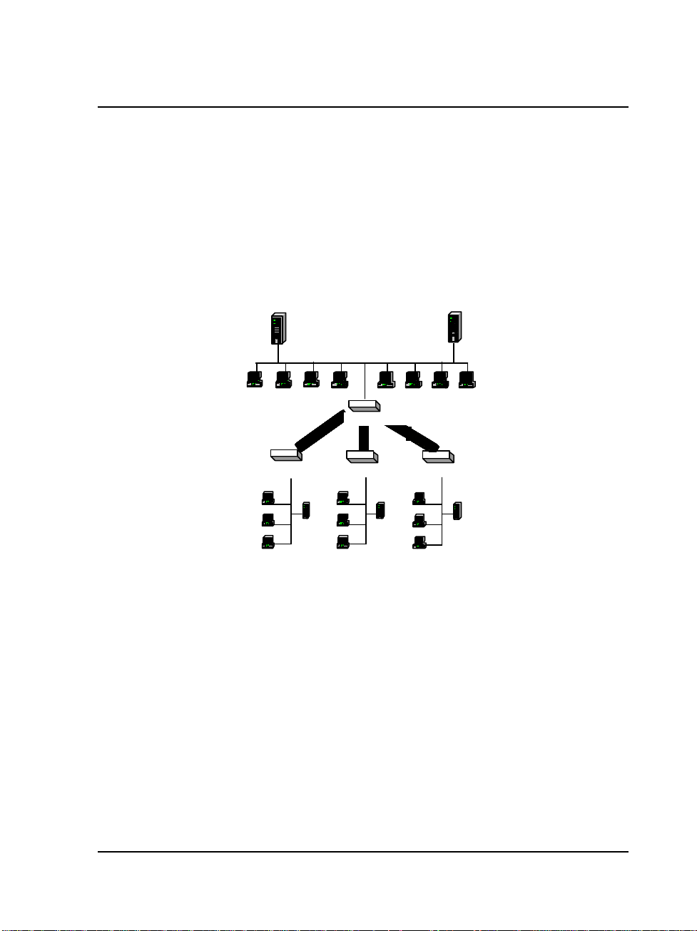
1.2.2 D-Link AirPremier DWL-1800 Functional
Description
The D-Link Air Premier DWL-1800Series, DWL-1800B (BU) and
DWL-1800R(RB), can be used as high-speed connections between two or more
remote networks.
Server
File
Central Network
BU-DS.11
DWL-1800B (BU)
Base Unit
Mail
Server
RB-DS.11
DWL-1800R (RB) DWL-1800R (RB) DWL-1800R (RB)
1
RB-DS.11
2
ServerServer
Remote Network 2Remote Network 1
RB-DS.11
3
Server
Remote Network 3
Figure 1: DWL-1800 Point-to-Multipoint Application
1.2.2.1 DWL-1800B (BU) Wireless Base Unit
The DWL-1800B is an IEEE 802.11b compliant base station that connects one or
more remote sites to a central server or Internet connection. In a point-to-multi-point
configuration the DWL-1800B is the central unit while in point-to-point
configurations it should be installed at one end of the link.
The DWL-1800B is the basic unit, equipped with an antenna inte grated into the
front cover of the outdoor unit.
2
Page 8

1.2.2.2 DWL-1800R (RB) Wireless Bridge
The DWL-1800 Wireless Bridge connects a remote Ethernet network to a central
network server or Internet site via a DWL-1800 Multipoint Base .
The maximum number of MAC addresses that the unit can handle at any specific
time is 1024 and the Aging algorithm is applied at all times.
When a station on the Ethernet LAN sends a message that is not destined for a local
station, the DWL-1800R forwards the message to the DWL-1800B. Whe n the
DWL-1800B receives a message destined for a station on the DWL-1800R's LAN,
the DWL-1800B wirelessly forwards it to the DWL-1800R. In this manner, the
DWL-1800R and the DWL-1800B work together like a standard network bridge.
The first time each station on the DWL-1800R’s LAN sends a message, the station’s
address is registered by both the DWL-1800R and the DWL-1800B. It is possible
for the DWL-1800R and DWL-1800B to store all the addresses necessary to support
an entire LAN connected to a DWL-1800R.
The DWL-1800R is the basic unit, equipped with an antenna integrated into the
front cover of the outdoor unit.
1.2.3 D-Link AirPremier DWL- 1800 Compatibility and
Standards
D-Link Air Premier DWL-1800 products are compatible with the following
standards and are interoperable with other IEEE 802.11b compatible, 2.4 GHz direct
sequence products.
?? IEEE 802.11b Wireless LAN.
?? IEEE 802.3 10BaseT Ethernet.
?? DHCP for automatic IP address assignment.
?? SNMP for system management.
3
Page 9

2. INSTALLATION
2.1 Packing List
Verify that all of the following items are included with the unit:
?? Indoor unit.
?? Outdoor unit (includes integrated antenna).
?? Pole mounting kit for the Outdoor unit (includes two brackets and four
sets of screws, nuts and washers).
?? 110/220 VAC Power Cord.
?? 20 meter Indoor -to-Outdoor cable.
?? 3 shielded RJ-45 connectors.
?? Configuration Utility CD including manual.
2.2 Installation Overview
1. Select appropriate locations for the outdoor unit, the antenna and
the Indoor unit.
2. Mount the outdoor unit.
3. Connect a ground cable from the outdoor unit to an appropriate
grounding point.
4. Connect the Indoor-to-Outdoor cable to the outdoor unit and route it
to the location selected for the indoor unit. Refer to Appendix B for
instructions on preparing the Indoor -to-Outdoor cable.
5. Mount the indoor unit. Connect the Indoor -to-Outdoor cable to the
indoor unit’s Radio port.
6. Connect the indoor unit’s Ethernet port to the user’s network
using an Ethernet cable.
7. Configure the unit’s parameters.
8. Align the antenna and verify connectivity with any other units.
NOTE: The indoor unit should be connected to the power source only
after it has been connected to the outdoor unit.
4
Page 10

Figure 2: General Installation Scheme - Pole Mounting
NOTE: Use a straight Ethernet cable to connect the indoor unit to a hub, or
use a crossed cable to connect it directly to a PC’s Network Interface
Card (NIC).
2.3 Outdoor Installation Considerations
This chapter describes various considerations to take into account when planning an
outdoor installation including site selection, antenna alignment, antenna
polarization and cell size.
5
Page 11

2.3.1 Collocating DWL-1800 Outdoor Units
Up to three DWL-1800B units with integrated antennas (the exact number depends on
the number of non-overlapping channels available in the relevant regulatory domain)
can be collocated on the same building top or tower. Collocating more then three units
may decrease performance depending upon the type of antenna and its direction. Each
unit should be assigned to one of the non-overlapping channels: 1, 7, or 13 in ETSI or
1, 6 or 11 in FCC.
2.3.2 Site Selection Factors
When selecting a location for outdoor units and external antennas, remember to take
into consideration the following guidelines:
?? Minimum distance between sites.
?? Maximum height above the ground.
?? Maximum line of sight clearance.
Path of Clearest Propagation
A propagation path is the path that signals traverse between the antennas of any two
units. The “line” between two antenna sites is an imaginary straight line, which may
be drawn between the two antennas. Any obstacles in the path of the “line” degrade
the propagation path. The best propagation path is, therefore, a clear line of sight
with good clearance between the “line” and any physical obstacle.
Physical Obstacles
Any buildings or other physical structures such as trees, mountains or other
geographic features higher than the antenna and situated in the path between the two
sites can constitute obstructions and cause signal attenuation. Install outdoor
antennas high enough to avoid any obstacles, which may block the signal.
6
Page 12

Path Loss
Path loss is determined mainly by several factors:
?? Distance between sites – Path loss is lower and system performance
better when distances between sites are shorter.
?? Clearance – Path loss is minimized when there exists a clear line of
sight. The number, location, size, and makeup of obstacles determine
their contribution to path loss.
?? Antenna height – Path loss is lower when antennas are positioned
higher. Antenna height is the distance from the imaginary line
connecting the antennas at the two sites to ground level. Ground level in
an open area is the actual ground. In dense urban areas, ground level is
the average height of the buildings between the antenna sites.
2.3.3 Rooftop Installation
Rooftop installations offer several advantages:
?? Fewer obstacles in the path.
?? Improved performance due to greater height.
2.3.4 Antennas for Outdoor Applications
The D-Link AirPremier DWL-1800 series can be used in point-to-point or
point-to-multipoint configurations.
Point-to-Point
The DWL-1800B/DWL-1800R is equipped with a directional antenna. The required
antenna gain depends on the required range and performance.
Point-to-Multipoint
Setting up a point-to-multipoint link requires the use of a base unit equipped with an
integrated antenna and at least two remote units also equipped with integrated
antennas.
7
Page 13

2.3.5 Antenna Polarization
Antenna polarization must be the same at both ends of the link. In most applications,
the preferred orientation is vertical polarization, which is best for above ground
propagation.
2.3.6 Cell Size/Link Distance
Cell size is determined by the maximum possible distance between the DWL-1800B
and a DWL-1800R unit. For open outdoor areas with an unobstructed line of sight
between the BU-DWL-1800B and the DWL-1800R units, the suggested maximum
distance is up to 6 miles (10Km) where ETSI is the regulatory domain and 15 Miles
(25 Km) where FCC is the regulatory domain.
2.3.7 Using Outdoor Range Tables
Specific range tables, guidelines and information about extended cables can be
obtained from your local dealer or the D-Link central offices.
Outdoor installations must have a clear line-of-sight between antennas. Solid
obstacles such as buildings or hills can prevent the establishment of a link while
partial obstacles such as trees or traffic can reduce range. Extended coaxial cables
can cause an increase in signal loss and a reduction in range.
2.3.8 Precautions
NOTE: Outdoor units and antennas should be installed ONLY by experienced antenna
installation professionals who are familiar with local building and safety codes
and, wherever applicable, are licensed by the appropriate government
regulatory authorities.
The system complies with the ETS 300 385 standard and is protected against
secondary lightning strikes when its outdoor unit is properly grounded
according to the applicable country-specific industry standards for protection
against lightning. The system complies with EN 61000-4-5, test level 3 (2kV).
Failure to do so may void the D-Link Air Premier DWL-1800 Product
Warranty and may expose the end user to legal and financial liabilities. D-Link
and its resellers or distributors are not liable for injury, damage or violation of
government regulations associated with the installation of detached antennas.
8
Page 14

2.3.9 Compliance with Radio Regulations
Regulations regarding maximum antenna gains vary from country to country. It is
the responsibility of the end user to operate within the limits of these regulations as
well as to ensure that the professional installer is aware of these regulations.
Violat ion of government regulations exposes the end user to legal and financial liabilities.
D-Link , its resellers and distributors shall not be liable for expense or damage incurred as
a result of installations that exceed local transmit power limitations.
2.4 Installing the Outdoor Unit
The outdoor unit can be secured to the pole using one of the following options:
?? Special brackets sets (supplied with each unit). There are two pairs of
screw holes on the units, allowing the use of the brackets with various
pole widths.
?? U-bolts - size A (inner installation holes, up to 2" pole).
?? U-bolt - size B (outside installation holes, up to 3" pole).
?? Metal bands (9/16” wide, minimum 12” long).
Figure 3 shows the locations of the holes, grooves and screw holes on the back of
the unit.
Figure 4 illustrates the method of installing a unit on a pole using the supplied
brackets.
NOTE: Make sure to install the unit with the bottom panel (the panel with the signal
strength bar and LEDs) facing downward.
9
Page 15

Figure 3: Holes/Grooves/Screw Holes
10
Page 16

Figure 4: 3” Pole Mounting Installation Using the Supplied Brackets
NOTE: When inserting the open-ended screws, make sure to insert them with the
grooves pointing outwards; these grooves are intended to allow fastening of the
screws with a screwdriver.
2.4.1 Connecting the Ground and Antenna Cables
The Ground terminal (marked ) is located on the bottom panel of the outdoor unit.
1. Connect one end of the grounding cable to the Ground terminal and
connect the other end to a good ground connection.
2.4.2 Connecting the Indoor-to-Outdoor Cable
1. Remove the two screws holding the waterproof seal to the outdoor unit
and remove the waterproof seal.
2. Unscrew the top nut from the waterproof seal.
Figure 5: The Waterproof Seal
11
Page 17

3. Route a straight, uncrimped Ethernet cable (8-wire, 24 AWG) through
both the top nut and the waterproof seal.
NOTE: The 8-wire cable should be shielded.
4. Insert and crimp the RJ-45 connector. Refer to Appendix B for
instructions on preparing the RJ-45 cable connector.
5. Connect the Ethernet cable to the Outdoor unit RJ-45 connector.
6. Replace the waterproof seal and then the top nut. Make sure that the
external jack of the cable is well inside the waterproof seal to guarantee a
good seal.
7. Route the cable to the location selected for the Indoor unit.
2.5 Installing the Indoor Unit
Route the Indoor -to-Outdoor cable into the building so that it conveniently reaches
the indoor unit while avoiding interference sources. It is recommended that the
cable be a little longer then necessary. The cable is supplied open ended so it can be
conveniently threaded as shown into the building.
1. Remove the wall-mounting bracket clipped to the back of the indoor unit
and mount it on a wall as shown in Figure 6. Mount the indoor unit on
the mounting bracket.
2. Assemble an RJ-45 connector with a protective cover on the indoor side
of the Indoor -to-Outdoor cable. Refer to Appendix B for instructions on
preparing the RJ-45 cable connector.
3. Connect the Indoor -to-Outdoor cable to the Radio connector, located on
the top panel of the indoor unit shown in Figure 8 on page 14. The
Indoor-to-Outdoor cable should be connected to the unit before the unit
is connected to the mains power.
12
Page 18

Figure 6: Wall Mounting the Indoor Unit
NOTE: The color codes of the power cable are:
brown phase ~
blue neutral 0
yellow/green grounding
4. After connecting the outdoor unit to the indoor unit using the
Indoor-to-Outdoor cable, connect the power cord to the unit’s AC
socket, located on the bottom panel shown in Figure 7. Connect the other
end of the power cord to the AC mains after verifying that the unit is
rated for the voltage in the country of use; the AC rating is indicated on
the bottom panel of the Indoor unit.
Figure 7: Indoor Unit Bottom Panel
13
Page 19

5. Verify that the yellow POWER LED located on the top panel is lit,
indicating that the unit is supplying power to the radio port.
Figure 8: Indoor Unit Top Panel
6. Connect the 10BaseT connector to the network. The cable connection
should be straight Ethernet if connecting the Indoor unit to a Hub and a
crossed cable if connecting it directly to a PC Network Interface Card
(NIC).
NOTE: The length of the Ethernet cable connecting the indoor unit to the
user's equipment, together with the length of the Indoor-to-Outdoor
cable, should not exceed 90 meters.
2.5.1 Configuring Parameters
Before aligning the antenna, certain key parameters must be configured to
enable connectivity with linked units.
See Unit Configuration Mode on page 209 for more information.
2.5.2 Antenna Alignment
Usually, low gain antennas do not require alignment due to their very wide radiation
pattern. High gain antennas, including the integral antenna of DWL-1800 units,
have a narrow beamwidth necessitating an alignment procedure in order to optimize
the link.
Check the antenna alignment by using the RSSI bar on the bottom panel of the
DWL-1800R unit.
To align the antenna:
1. Confirm that the units at both ends of the link are receiving power.
14
Page 20

2. Synchronize the units by aligning the antennas at the central and remote
sites until maximum signal quality is obtained. Check the signal quality
RSSI bar on the bottom panel of the DWL-1800R. The first LED lights
red to indicate that the unit is working. The remaining nine LEDs light
green to indicate the signal strength. The stronger the signal, the more
LEDs are lit. Rotate the antenna to the left or right until you reach the
point of maximum RSSI reading. Make sure that at all times the front of
the antenna faces the general direction of the DWL-1800B.
15
Page 21

2.6 Verifying Correct Operation
2.6.1 Verifying Correct Operation of the Indoor Unit
To verify proper operation, check the LED indicators located on the top panel of the
indoor unit as shown in Figure 8 on page 14, and as described in Table 1.
Name Description Functionality
POWER Power indication
LINK Self Test and Ethernet
Link indication
Table 1: Indoor Unit LEDs
Green - 48VDC is present on the Radio
RJ45 port.
Off - No power is supplied to the Radio
RJ45 port.
The LINK LED indicates end-to-end
connection between the outdoor unit and
the Ethernet connection to the indoor
unit.
Off – No Ethernet connectivity has been
detected between the outdoor unit and
the device connected to the indoor unit.
Orange– Self -test passed and Ethernet
connection is confirmed by the Outdoor
unit (Ethernet integrity check passed).
16
Page 22
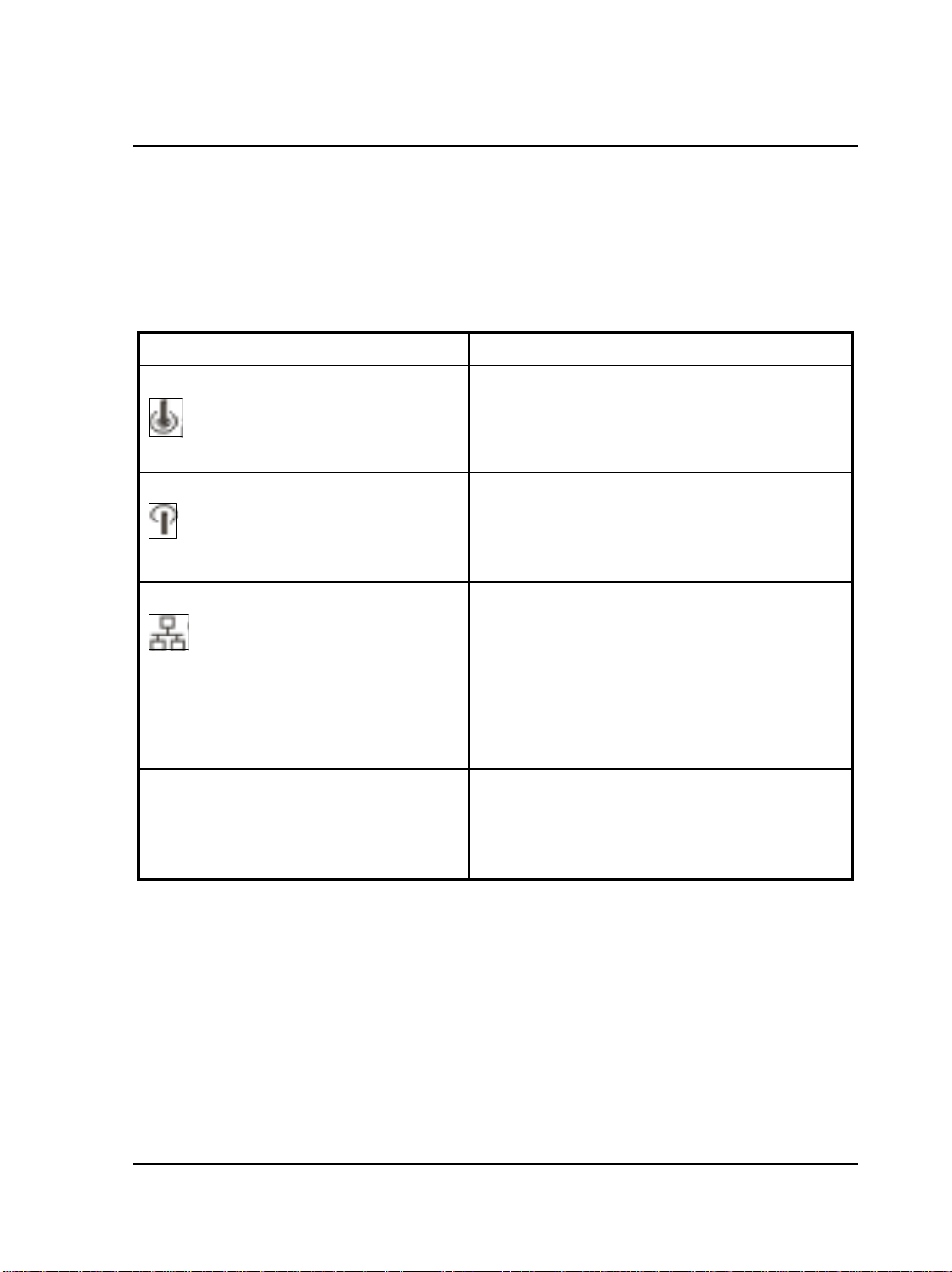
2.6.2 Verifying Correct Operation of the Outdoor Unit
To verify proper operation, check the LED indicators located on the bottom panel of
the outdoor unit.
Name Description Functionality
WLAN Wireless Link
Indicator
DC Power Self Test and Power
indication
ETH
Ethernet activity/
connectivity indication
RSSI
DWL-1800R: Received Signal Strength
BAR
Blinking Green – Data received or
transmitted on the wireless link. Blinking
rate is slower when there is less wireless
traffic.
Green – Power is available and self test
passed.
Red – Self test failed. Firmware did not
load successfully.
OFF –Ethernet connectivity is OK.
No traffic activity detected on the port.
Blinking Green –Ethernet connectivity is
OK, with traffic on the port.
Red – No Ethernet connectivity. When
this state occurs, check the Ethernet cable
and Indoor -to-Outdoor cable connections.
Indication
DWL-1800B: Number of associated
RB-DWL-1800R units
Table 2: Outdoor Unit LEDs
What to do if the Self Test fails
If the Self -Test failed (DC Power LED light remains red), try the following:
?? Reset unit (Disconnect/reconnect the power).
?? Check the Indoor -to-Outdoor cable.
?? Reset to factory defaults (see page 42).
?? Contact technical support.
17
Page 23

3. THE D-LINK AIRPREMIER DWL-1800
CONFIGURATION UTILITY
The D-Link Air Premier DWL-1800 Configuration Utility is an SNMP -based utility
that provides a consistent view of the wireless network. The system administrator
can use the D-Link AirPremier DWL-1800 Configuration Utility to control a large
number of DWL-1800 units from a single location. The Configuration Utility can be
used to manage DWL-1800B(BU) and DWL-1800R (RB)units as well as other
members of the D-Link wireless family including D-Link Air and Air Plus Series
i.e. DWL-900AP, DWL-900AP+, DWL-520, DWL-520+, DWL-650, DWL-650+.
The description in this manual, however, is limited to management and
configuration of DWL-1800B and DWL-1800R units.
Using the Configuration Utility you can:
?? Assign radio channels for optimal cell operation.
?? Configure units with a specified IP address.
?? Set the SNMP Read/Write Community strings.
?? Verify the status of all units in the network.
?? Configuration of a wide range of operational parameters, including
WLAN, IP and Security parameters.
?? View Tx and Rx counters.
?? Obtain general information such as the Firmware version and system
name.
18
Page 24

3.1 Installing and Running the Configuration
Utility
The Configuration Utility is provided for installation on a 3.5” diskette.
1. Insert the provided diskette into the computer where you wish to
install the Configuration Utility.
2. Run Brzmgr mgr.exe.
3. Follow all instructions until you are informed that the Utility was
installed successfully.
4. Run the Configuration Utility from the Start menu by selecting it in
the D-Link AirPremier DWL-1800 Configuration Utility folder under
Programs.
3.2 Configuration Utility Modes
There are several D-Link AirPremier DWL-1800 Configuration Utility modes of
operation; these options are selected via the Mode menu in the configuration utility
main window (shown below). The selected mode(s) is indicated by a check mark in
the menu.
?? Unit configuration - This is the default mode and is used for setting
parameters as detailed in this manual.
?? Firmware upgrade – Used for upgrading the embedded software in
managed units; refer to Section 3.2.2 for instructions on using this
feature.
?? Multiple configuration – Used for setting configuration parameters for
more than one unit simultaneously; refer to Section 3.2.3 for
instructions on using this feature.
19
Page 25

?? Trap quick view - When set to this mode, the PC (if set as described in
Section 3.2.1.3.3) switches automatically to the Trap Monitor tab when
Unit Configuration mode is selected.
3.2.1 Unit Configuration Mode
The Control Window Section
In this section, you can:
?? Discover the units that are connected to the network.
?? View DWL-1800 units that have been discovered by their IP address.
?? Select the units you wish to manage.
?? Locate units behind a router that cannot be detected by the autodiscovery
feature
?? Assign unit IP addresses based on unit MAC addresses.
?? Set the SNMP Community string.
If there are many units in the managed network, you can enlarge the list box by
clicking on the horizontal line above the list; click again to toggle back the default
display state. The list box also displays the Location of each unit, as set in the
Station Status dialog box (see Section 3.2.1.3.1).
The Tabs Section
This section consists of several tabs, each containing parameters required for the
management of the selected unit; the number of tabs displayed varies between the
type of managed unit. The different tabs are described in the following sections.
When you switch between the tabs, the unit selection section with the selected unit
address remains displayed.
20
Page 26

Control
Window
Tabs
Section
Figure 9: D-Link AirPremier DWL-1800 Configuration Utility Main Window (Station
Control Tab)
3.2.1.1 The Control Window
3.2.1.1.1 Selecting Units
You can select a unit to manage in one of the following ways:
?? Click the Network Autodiscovery button. All the IP addresses of units in
the same domain but not hidden behind a router (under the selected
community) are displayed in the list box underneath the button. Click on
an address to select the corresponding unit for viewing and
configuration.
?? Type the unit's IP address in the Locate Unit field (for stations which are
located behind a router) and click . This will add the unit
information to the selection list.
21
Page 27

3.2.1.1.2 Setting the SNMP Community String
Type the known Read/Write Community string in the Community field (the default
string is public for read and private for read/write) and click the button to
confirm.
3.2.1.1.3 Assigning and Editing IP Addresses Manually (based on MAC
addresses)
1. Click the Set IP button. The Set IP dialog box appears.
Figure 10: The Set IP Dialog Box
2. Type the parameters in the appropriate fields and click OK; the MAC
address is shown on the bottom label of the Indoor and Outdoor units. A
message box is displayed notifying you when the changes are to take
affect. This feature can be used only if the D-Link AirPremier
DWL-1800 Configuration Utility is on the same Ethernet segment as the
unit and not behind the router.
22
Page 28

NOTE: In order to see the unit after assigning the IP address, the PC with
the Configuration utility should be on the same IP subnet as the
assigned IP address.
Units receive auto IP address if there is no DHCP server and the unit
is configured to work in the Smart mode as described in Section
3.2.1.3.2. The IP address will be chosen randomly in the 169.254.x.x
range with a subnet mask of 255.255.0.0.
3.2.1.2 Application Control Buttons
The following buttons always appear at the bottom of the Configuration Utility
window. Additional buttons, specific to certain tabs, are explained when relevant.
?? Hide to Tray – Minimizes the application into the icon, placed in
the Windows task bar (at the bottom of the Windows desktop). To
restore the application, click the icon.
?? Apply – Implements any changes you made.
?? Refresh – Refreshes the window with the most recent data from the unit.
?? Cancel – Closes the window without implementing any changes you
made.
.
23
Page 29

3.2.1.3 Configuration Utility Tabs
3.2.1.3.1 Station Status Tab
The Station Status tab displays general information regarding the unit's firmware
and hardware versions as well as general unit address information.
Figure 11: Station Status Tab
?? System Name - The name of the selected unit.
?? Location - A user-defined description of the location of the selected
unit, up to 28 ASCII characters long (optional).
?? MAC Address - MAC address of the selected unit.
?? Firmware - The current firmware version.
?? BSS Address (DWL-1800R units only) - Defines the MAC address of
the BSS, which is the DWL-1800B the unit is associated with.
3.2.1.3.2 IP Parameters Tab
The IP Parameters tab allows you to define or edit the IP parameters of units.
24
Page 30

Figure 12: IP Parameters Tab
?? IP Address - The IP address of the selected unit.
?? Subnet mask - The Subnet mask of the selected unit.
?? Default gateway - The default gateway of the selected unit.
?? DHCP - Sets the way your system utilizes the Dynamic Host
Configuration Protocol (DHCP, used for automatic IP assignment).
Always - The system searches for a DHCP server each time the unit
is turned on.
Smart - The system searches for a DHCP server only if no IP
address was assigned. If an IP address was assigned manually, the
system will not search for a DHCP server.
Never - The system never searches for a DHCP server.
The default value is Smart.
NOTE: When the unit is configured to use a DHCP server and none exists, the unit will
assign itself an automatic class B address in the range 169.254.X.X; this can be
used with Auto Discovery when the MAC address is not available.
25
Page 31

3.2.1.3.3 SNMP Parameters Tab
The SNMP parameters tab allows you to define or edit the SNMP community
strings and the SNMP -related parameters.
Figure 13: SNMP Parameters Tab
?? Read - The read-only community string of the unit. Default is public.
?? Read/Write - The read/write community string of the unit. Default is
private. This value is displayed as asterisks for security purposes.
?? Trap Host IP Address - The IP address of the host to which SNMP
traps are sent.
Click the icon directly beneath this field to apply the defined Trap Host
IP address.
Click the icon directly beneath this field to disable the sending of traps
(inserts a value of 255.255.255.255).
26
Page 32

3.2.1.3.4 Counters Tab
Figure 14: Counters Tab (BU/DWL-1800B Units)
Figure 15: Counters Tab (RB/DWL-1800R Units)
Using the Counters windows, you can view a wide range of performance data at
both sides of the link. For RB units, you can monitor the received signal strength
through the RSSI (Received Signal Strength Indication) bar indicator at the bottom
of the window. This RSSI bar can be used to optimize antenna alignment and
improve link quality.
27
Page 33

Additional performance counters displayed in this window include the following.
To obtain a graph that displays the counter values, select a counter and drag it to the
icon.
?? Tx Counters
Tx Fragments - The number of transmitted frames. The count includes data,
control, management frames and the number of retransmissions of data
frames (for example, if the same data frame is retransmitted ten times then the
count will increase ten times).
Tx Frames - The number of frames transmitted to the wireless media. The
count includes the first transmission of data frames (without retransmissions),
and the number of control and management frames.
Multicast Tx Frames- The number of transmitted multicast frames.
Retry Count - The number of retransmissions.
Multiple Retry - This counter is incremented when a packet is successfully
transmitted after more than one retransmission.
Failed Count - This counter is incremented when a packet is not transmitted
successfully due to the number of transmit attempts exceeding either the
Short Retry Limit or Long Retry Limit.
?? Rx Counters
Rx Fragments - The number of frames received, including data, control, and
duplicate data frames.
Multicast Rx - The number of received multicast frames.
FCS Error - The number of CRC errors, in addition to the percentage of
CRC errors out of the total frames.
Frame Duplicate - The number of duplicate frames that were sent or
received.
?? Link Counters
The Tx Success and Tx Fail counters displayed at the end of the counters
list are link-specific; to activate these counters for a specific link, select
the MAC address of the unit at the other end of the link and click Apply.
When you click the Reset Counters button, these counters are actually
reset (unlike the other counters which are only reset on screen).
Tx Success - The number of successfully sent Request To Send frames.
28
Page 34

Tx Fail - The number of frames which the station failed to send.
?? Resetting Counters
You can reset the counters displayed in the Counters tab by clicking the Reset
Counters button. All displayed values are reset to display zero.
Note that this action does not reset the counters stored in the actual unit, but
just resets the values displayed in the screen (an exception to this are the Link
Counters). Therefore, if you exit the Counters tab, after performing a reset
and reopen it at a later time the counter values are displayed to reflect the
values stored in the unit. To reset the counters in the unit, turn off the unit and
then turn it back on.
3.2.1.3.5 WLAN Parameters Tab
The WLAN parameters tab allows you to define or edit parameters related to the
Wireless LAN environment in which the selected unit is operating. The window
displayed varies depending on the type of unit selected.
Figure 16: WLAN Parameters Tab (BU/DWL-1800B)
29
Page 35

Figure 17: WLAN Parameters Tab (RB/DWL-1800R)
?? Regulatory Domain - Displays the regulatory authorities in the relevant
country of use (e.g., Canada, ETSI, FCC, Japan).
?? Power - Displays the current output power level at the antenna port.
?? ESSID - An ASCII string of up to 32 characters used to identify a
WLAN that prevents the unintentional merging of two co-located
WLANs. It is essential that the ESSID is set to the same value in all
Remote Bridges and Base Units that should communicate with each
other. The ESSID field is case-sensitive.
?? Maximum data rate - By default, the unit adaptively selects the highest
possible rate for transmission. Under certain conditions (for range/speed
trade-off) you may decide not to use the higher rates. Possible values are
2, 5.5 or 11 Mbps. The default value is 11 Mbps.
?? Transmit diversity - The antenna diversity option, which must be set to
Antenna No. 1.
NOTE: In the present product release, antenna diversity is not supported;
therefore, always select Antenna No. 1.
30
Page 36

?? Range - The operative range of your WLAN or Wireless Link in the
drop down list. This parameter affects the acknowledge delay time
which needs to be increased in long links. The default value is up to
5 km.
?? Channel - Channel selection varies, depending on the type of unit.
For DWL-1800B units, select the channel that the unit will use by
selecting a value (range: 1-13, depending on your regulatory domain)
from the Channel drop down menu. Refer to Table 4 on page 32 for the
list of corresponding frequencies.
For DWL-1800R units, there are two channel setting options: if you
select the Fixed Channel option by clicking the appropriate radio button,
then the DWL-1800R will search for the DWL-1800B unit on the
selected channel (from the Channel pull down field) and synchronize
with it. The channel you select must match the channel selected in the
DWL-1800B unit at the other end of the link.
If you select the Scanning Mode option (by selecting the appropriate
radio button), you can specify preferred channels by clicking one or
more of the buttons displayed at the bottom of the window. In this mode,
the DWL-1800R will first search for the DWL-1800B unit on the
channel you select in the Channel pull down field and synchronize with
it if the link is established. If the DWL-1800R does not find the
DWL-1800B, it will scan and search for one of the preferred channel
frequencies you selected. If it does not find the DWL-1800B on any of
the preferred channels, it will continue to scan until it finds the
DWL-1800B on one of the channels permitted according to the
regulatory domain.
Table 3 describes the channels used in each regulatory domain, the
default channel, the maximum output power and the default output
power.
Regulatory
Domain
Lowest
Channel
Highest
Channel
Default
Channel
Max.
Output
Power
Default
Output
Power
ETSI 1 13 7 14 4
FCC 1 11 6 24 24
TELEC 1 13 7
31
14
6
Page 37

France 10 13 11 14 4
Canada 1 11 6 24 24
Table 3: Regulatory Domains Specifications
Channel Frequency
1 2412 MHz
2 2417 MHz
3 2422 MHz
4 2427 MHz
5 2432 MHz
6 2437 MHz
7 2442 MHz
8 2447 MHz
9 2452 MHz
10 2457 MHz
11 2462 MHz
12 2467 MHz
13 2472 MHz
Table 4: Frequency List
NOTE: The frequencies listed in the table are at the center of the channel. Each
channel occupies 22MHz, therefore each channel occupies
-11MHz to +11 MHz from the frequency specified.
32
Page 38

3.2.1.3.6 Station Control Tab
Figure 18: The Station Control Tab
?? Station Control - Click the Default button for all parameters to revert
to the factory defaults.
?? Reset Unit - Click the Reset button to reset the unit and apply any
changes made to the system parameters.
?? Export Configuration - Click the Export button to export the
current basic configuration of this unit to a file. A popup window is
displayed prompting you to specify the name of the file. The created
file can be used to save the configuration information or to send it to
tech support as a reference for troubleshooting.
33
Page 39

3.2.1.3.7 Security Tab
Figure 19: Security Tab
This tab displays information regarding the unit’s security configuration. Wired
Equivalent Privacy (WEP) is an authentication algorithm that protects authorized
Wireless LAN users against eavesdropping and is implemented in D-Link
AirPremier DWL-1800 units. WEP is defined in the IEEE 802.11b standard. This
encryption is applicable for both authentication and data and the key length is
40 bits.
D-Link AirPremier DWL-1800 units can use one of the following authentication
algorithms (as defined in the IEEE 802.11b standard).
?? Open System – Any station in the WLAN can associate with any
other unit and receive and transmit data freely(null authentication).
?? Shared Key – Only stations using a shared key encryption are
allowed to associate.
The default authentication algorithm is Open System.
34
Page 40

If you select the Shared Key algorithm, set the following parameters:
?? Default Key ID – Sets the key for encryption.
?? WEP Key – Defines the encryption keys used. Define each key by
clicking the appropriate WEP Key row and entering ten hexadecimal
characters (five sets of two characters each) for each of the four
keys. After clicking Apply, the WEP Key values are displayed as
zeros for security reasons.
The default WEP key is the first key.
NOTE: All units in the same cell should use the same key.
3.2.1.3.8 Advanced Tab
The Advanced tab provides additional performance parameters.
Figure 20: Advanced Tab
?? CW Min/Max - The size of the contention window. The contention
window backoff algorithm is a method used to resolve contention
between different stations trying to access the medium. The valid
range is from 7 to 1023.
Defaults are 31 for CW Min and 1023 for CW Max.
?? RTS Threshold - The minimum packet size required for an RTS
(Request to Send) to be sent. For packets with a size below the RTS
35
Page 41

Threshold value, an RTS is not sent and the data packet is transmitted
directly to the WLAN.
?? Short Retry Limit - The maximum number of transmission attempts
for a frame that is shorter than or equal to the RTS Threshold. The
default value is 8.
?? Long Retry Limit - The maximum number of transmission attempts
for a frame that is longer than the RTS Threshold. The default value
is 4.
?? Basic Rate - The maximum rate of multicast, broadcast and control
frames transmissions. Multicast and broadcast transmissions are not
acknowledged; therefore there is a chance that such transmissions
will not be properly received without the possibility of using the
acknowledgement mechanism for retransmission. Therefore, it is
recommended to use a lower rate for transmission of broadcast,
multicast and control frames, to increase the probability that they will
be received without errors. Enter the data rate at which broadcast,
multicast and control frames are transmitted. The default value is 2
Mbps.
NOTE: The Basic Rate parameter should be changed only if you are sure
that all units in the cell can handle the defined rate. Use this
parameter with caution, as it may bring the link down.
?? Power – The transmit power level. The possible range is
from –4dBm to +24dBm.
NOTE: The Power setting should not exceed the maximum output allowed
in the applicable regulatory domain according to Table 3 on
page 32.
36
Page 42

3.2.1.3.9 Trap Monitor Tab
Figure 21: Trap Monitor Tab
When an event occurs, a trap is sent to the defined host address (the
setting is made in the SNMP Parameters tab described in Section
3.2.1.3.3). This window displays the recorded traps.
Click the Clear List button to clear the display area.
3.2.2 Firmware Upgrade Mode
This mode allows the embedded software in managed units to be
upgraded. When you select this mode from the Options menu, the
following dialog box is displayed.
37
Page 43

Figure 22: Firmware Upgrade Mode dialog box
NOTE: The Configuration utility does not resolve the topology of the cell. Therefore,
firmware upgrades should be made from the central point where the
BU/DWL-1800B are located.
The list box on the left-hand side of the dialog box displays the managed units; it is
sorted sequentially by DWL-1800B followed by DWL-1800R units.
To upgrade firmware:
1. Select the units that you wish to upgrade from the list box. Use
Shift-click and/or Ctrl-click to select multiple units, or select multiple
units by dragging with the mouse.
2. Specify the firmware file you wish to use in the Local file name fields;
there are separate fields for files of different device type. The field text is
displayed in blue when corresponding unit types are selected in the list
box.
3. In the Remote File Name field, enter the Read/Write community string of the
unit(s).
4. Click Advanced if you wish to change the settings of the TFTP session
used in the upgrade download (see 3.2.2.1).
5. Click Start to initiate the firmware upgrade; progress bars are displayed
38
Page 44

indicat ing the progress of the operation. If both DWL-1800B and
DWL-1800R devices are selected, the program will upgrade
DWL-1800R units first.
At the end of the upgrade session, the following window is displayed
indicating that the operation was successful.
Figure 23: Firmware Upgrade Process
NOTE: Do not disconnect any cables or try to stop the process before downloading is
completed.
All configured parameters are saved during the upgrade/download procedure.
39
Page 45

3.2.2.1 Advanced TFTP Settings
Figure 24: Advanced TFTP Setup dialog box
The Advanced TFTP Setup window enables you to tune the TFTP session
parameters for a more efficient firmware upgrade, depending on your actual
deployment.
?? Packet timeout - Defines the time (in seconds) it takes for a packet
to timeout. The range is from 1 to 30 seconds with a default of
3 seconds.
?? Packet Retries - Defines the number of times that a packet will be
sent after it timeouts in a TFTP session. The range is from 1 to 5
retries with a default of 3 retries.
?? Session Retries - Defines the number of times a TFTP session
will be repeated before the firmware upgrade operation is
designated a failure. The range is 1-5 retries with a default of 3
retries.
40
Page 46

3.2.3 Multiple Unit Configuration Mo de
This feature allows configuration parameters to be downloaded to multiple units
simultaneously. When you select this option in the Options menu, all configuration
windows become write -only. Irrelevant parameters are disabled.
NOTE: The Configuration Utility does not resolve the topology of the cell. Therefore,
multiple unit configuration operations should be done at the location where the
DWL-1800B is are located.
Select the units that you wish to upgrade from the list box on the left-hand side of
any dialog box tabs. Use Shift-click and/or Ctrl-click to select multiple units.
Enter the configuration parameter values and click Apply. The following dialog box
is displayed.
Figure 25: Multiple Configuration Mode dialog box
This dialog box lists the selected units and displays the configuration changes to be
made during the multiple configuration session. Select the Reset units after setting
parameters check box to reset all selected units.
A log of the multiple configuration session is displayed during and after the operation.
41
Page 47

3.3 Resetting the SNMP Community Strings
The SNMP Read/Write Community strings are an SNMP security feature to restrict
management access to authorized persons only. Refer to Section 3.2.1.1.2
To reset the SNMP community strings, insert a paper clip or another suitable tool
into the Reset button on the top panel of the unit while the unit is operating. The
community strings are reset to the default values, private (Write) and public (Read).
3.4 Reloading Factory Default Settings
To reset the unit to the factory defaults:
1. Disconnect the power cable from the indoor unit.
2. Insert a paper clip or another suitable tool into the Reset button on the
top panel of the unit (see Figure 8 on page 14). Keep the Reset button
pressed while inserting the power cable back into its socket.
42
Page 48

4. SYSTEM TROUBLESHOOTING
The following troubleshooting guide provides answers to some of the more
common problems that may occur when installing and using the D-Link Air Premier
DWL-1800. If problems not mentioned in this guide should arise, checking the
Ethernet and WLAN counters may help (see Section 3.2.1.3.4). If the problem
persists, please feel free to contact your local distributor or the D-Link Technical
Support Department.
4.1 Troubleshooting Guide
Problem and
Indication
No power to unit.
Power LED is off.
Failure to establish
wireless link.
WIRELESS LINK
LED is off and unit
resets every few
minutes.
Possible Cause Corrective Action
Power cord is not properly
connected.
1. Power supply to units
may be faulty
2. The DWL-1800R units
may not have the same
ESSID as the
DWL-1800B.
Verify power cord is properly connected to
the DWL-1800 unit and to the power outlet.
1. Verify power to units.
2. Verify that all units in the network have
the same ESSID (ESSID must be identical
in all units in the WLAN; the ESSID is case
sensitive). Check that the units are on the
same channel.
3. Verify wireless link
?? Set DWL-1800B and
DWL-1800R units side by side.
?? Power on each unit and see if a
wireless link is established (even
“D” models without their external
antennas should establish a link if
placed side by side).
?? If the units fail to associate, reset
units to factory default values (see
Section 3.4). The units should
now establish a wireless link.
43
Page 49

Problem and
Indication
Failure to establish
wireless link (“D”
models/external
antennas)
Wireless link
established, but
there is no
Ethernet activity
(DWL-1800B and
DWL-1800R
units).
Possible Cause Corrective Action
1. Power supply to
units may be faulty.
2. Cables may be
improperly connected
3. There may be some
problem with antenna
installation.
1. Verify power to units.
2. Verify that all cables are connected securely.
3. Refer to previous Section and
verify wireless link between the
units.
4. Verify that the antenna(s) are
properly installed (see relevant
section in this manual):
?? Check antenna alignment.
?? Verify that antenna
polarization is the same at
both ends.
?? Verify that the range
matches specifications.
?? Verify line-of-sight/antenna
alignment/antenna height.
1. Ethernet hub port or
UTP cable is faulty.
2. Ethernet port in unit
is faulty.
3. The DWL-1800R
is associated to a
DWL-1800B unit that
is not connected
correctly to the LAN.
1. Check that the LINK LED is lighted
Green. If this is not the case, the port is
inactive. Try another port on the hub or
another UTP cable.
2. Verify that Ethernet port in unit is
working. Ping unit to verify Ethernet
connection.
3. Verify that you are using a cross-over
UTP cable (pins 1 & 3, 2 & 6) if
connected directly to a workstation, or a
straight-through cable if connected to a
hub.
4. Check the unit’s LINK LED indicator
and check the Ethernet counter s in the
monitor to verify Ethernet activity (see
Section 3.2.1.3.4).
5. Check that the DWL-1800B is
correctly connected to the LAN.
44
Page 50

5. TECHNICAL SPECIFICATIONS
5.1 Supported Standards
?? Compliant with ETS 300 328 and ETS 300 826 (CE marked).
?? IEEE 802.11b HR standard for Wireless LAN at 11 and 5.5
Mbps.
?? IEEE 802.11b standard for 1 and 2 Mbps.
5.2 Configuration and Management
Management and
Setup
Site Survey Tool
SNMP Agents
Software Upgrade
LED Indicators
5.3 Radio
Frequency Range
Radio Type
Wireless LAN
Standards
Selectable sub
Channels
SNMP based Configuration Utility
Integrated into the configuration utility
MIB II, Bridge MIB, DWL-1800 Private MIBs
Simultaneous multiple units software
upgrade using the configuration utility
TFTP download
Indoor Interface
Unit
Power status Power Status
End-to-end
Ethernet status
Ethernet Status / Traffic
2.4 - 2.4835 GHz ISM band (ETSI, FCC)
2.4 - 2.4835 GHz (Japan)
Direct Sequence Spread Spectrum (DSSS)
Compliant with IEEE 802.11b HR
FCC 1-11
ETSI 1-13
Japan TELEC 1-13
Outdoor Unit
10-LED display bar:
RSSI in the RB/ Load
Gauge in BU
Wireless Link Status /
Traffic
Page 51

France 10-13
2, 4, 6, 12, 14
Output Power
(at the antenna
port)
FCC -4, -2, 4, 6, 12, 14, 20, 24
ETSI -4, -
(dBm)
Japan TELEC -4, -2, 4, 6, 12, 14
Data Rate Sensitivity Modulation
Sensitivity
(BER 10E-6)
Processing Gain
Integrated
11 Mbit/s -85 dBm 256 CCK
5.5 Mbit/s -88 dBm 16 CCK
2 Mbit/s -90 dBm DQPSK
1 Mbit /s -93 dBm DBPSK
10.4 dB Nominal
Flat Panel 16 dBi, 20? Vertical /Horizontal
Antenna Type
5.4 Range
Europe/ ETSI (20
dBm EIRP)
US FCC Up to 25 km (15 miles)
Up to 10 km
5.5 Security
Authentication
and Data
40-bit RC4 WEP
5.6 Outdoor Un it-to-Indoor Unit Communication
Cable Type
Maximum Cable
length between units
5.7 Interfaces
RF (antenna) connector
in the outdoor unit
(DWL-1800D models)
Cat 5 FTP 4x2x24 Double Jacket
90 m (280 feet)
N-Type jack, lightning protected
46
Page 52

Baseband
(indoor-to-outdoor
units)
Ethernet
5.8 Electrical
Power Consumption
Outdoor units: Shielded RJ-45 with
special water proof sealed cap
Indoor units: Shielded RJ-45
Indoor units: 10BaseT, (RJ-45) with 2
embedded LEDs
110 /220 V
500 /250 mA
47
Page 53

5.9 Mechanical Dimensions
Outdoor Unit
30 x 30 x 7.2 cm
12 x 4.7 x 2 in
Indoor Unit
15.4 x 8.4 x 5.6 cm
6.1 x 3.3 x 2.2 in
5.10 Environmental
Operating Temperature
Operating Humidity
Indoor unit: 0?C to 40?C
Outdoor unit: -40?C to 55?C
5% to 95% non -condensing. Outdoor
units are weather protected.
5.11 Standards Compliance, General
EMC
Safety
Environmental
Radio
EN 300-385, FCC Part 15
EN 60950, UL 1950
ETS 300 019
ETSI ETS 300 328, FCC Part 15
48
Page 54

APPENDIX A. DWL-1800 FAQ
General
Can the DWL-1800R indoor unit be placed outdoors?
It is not recommended. The DWL-1800 indoor units are specified to operate
between 0?C and 40?C and is not weather proof so it is best to mount the
DWL -1800R indoors or in a protective cabinet.
Do DWL-1800 units support 802.1Q VLAN?
Yes, but the support is limited to transparent operation. This means that the
DWL -1800 does not take any action on 802.1Q frames, but will transparently
pass them within a VLAN network.
What is the maximum number of networked PCs the DWL-1800B/
DWL-1800R can learn?
1024 network MAC addresses can be learned by the DWL-1800B/DWL-1800R
from the LAN side.
Can the DWL-1800B/DWL-1800R be used for multi-point as well as
point-to-point links?
Yes. The DWL-1800B can support multiple DWL-1800R units creating a
point-to-multi -point network.
How many DWL-1800R units can one DWL-1800B support?
The maximum number of associations is 128.
What is the practical limit to the number of DWL-1800R units per
DWL-1800B? And, what performance can I expect for a multi-point link?
This depends upon average throughput expectations. All clients would have the
maximum throughput available for burst traffic, however the overall average would
depend on the utilization of the network. For example, in a heavily utilized network
needing about 350Kbps to 500kbps average net throughput per site, 9 to 12
DWL-1800R’s would be the limit. For a moderately utilized network needing about
175Kbps to 258Kbps average, 18 to 24 DWL-1800R’s should be used, and for a
lightly used network needing 32Kbps to 48Kbps average net throughput per site
could use up to 128 DWL-1800R’s.
What is the range of the DWL-1800B/ DWL-1800R Bridges?
49
Page 55

15 miles/24Km (FCC) or 10 KM (ETSI) can be achieved using the UNI-24 antenna
kit for a point-to-point link. Consult the antenna and accessory guide range tables
for distances using other antennas.
Does the DWL-1800B supports 802.1d spanning tree protocol?
No, the DWL-1800B/DWL-1800R does not support spanning tree.
What is the normal PER (Packet Error Rate) for the
DWL-1800B/DWL-1800R?
The error rate will be about 4%-6% (transmitted fragments vs. retry count). This is typical
when operating in a non-interference environment at maximum range for bi-directional
traffic loads. If the traffic load is more uni-directional, then the PER will be less.
What is the best value for the CW min parameter on the DWL-1800?
Setting the CW min parameter to 31 for heavy bi-directional traffic loads will
minimize the PER. Setting the CW min to 15 will improve performance for mor e
uni-directional traffic loads. CW min 7 should only be used for short-range
point-to-point links, and 63 should be used for large, long-range multi-point links.
Is the D-Link Air Premier DWL-1800 compatible with other D-Link
wireless equipment from other vendors?
Yes. However, for the outdoor bridges, interoperability can vary from vendor to vendor
and in some cases it may not operate if the manufacturer’s implementation is not pure
802.11b. The DWL-1800B/DWL -1800R can operate at 1, 2Mbps 5.5Mbps and 11Mbps
with D-Link Air and Air Plus wireless family products. D-Link Air Premier DWL -1800
units are fully WI-FI compliant.
50
Page 56

Collocation
How many DWL-1800B or DWL-1800R units can be collocated on the
same building or tower?
You can collocate up to 3 DWL-1800B or DWL-1800R units on the same structure.
Each unit is assigned to one of the non-overlapping channels, 1, 6, or 11.
Can a Frequency Hopping network operate in the same area as the
D-Link Air Premier DWL-1800?
Yes, but in a collocated network both products will suffer some a decrease in
performance. The degree of performance loss depends on network utilization. For
example, the higher the utilization of the Frequency Hopping network, the higher
the level of impact on the Direct Sequence (DWL-1800) network, and vice versa.
Typically, in light to moderately utilized networks, the performance loss is not
significant.
Can I use D-Link Air Premier DWL-1800 Bridges to feed a Frequency
Hopping distribution point?
Yes, bandwidth sharing between the Direct Sequence and Frequency Hopping
products can be minimized if the network is designed using cross-polarized
directional antennas with as much spatial separation as possible. Contact technical
support for more information.
51
Page 57

Performance
What is the throughput of the D-Link Air Premier DWL-1800?
The DWL-1800B/DWL-1800R bridge link typical performance is 4.2Mbps using
TCP and 6.2Mbps using UDP. For long-range links, the performance drops by
about 5%.
What if the D-Link Air Premier DWL-1800 link experiences interference?
If interference is affecting the DWL-1800 link, one of the other channels may be
selected to operate away from the frequency of the interference. Also, physically
re-locating the antennas may help.
What is the typical latency of a DWL-1800B/DWL-1800R?
A point-to-point link would realize about 3mS latency.
52
Page 58

Firmware
Can the DWL-1800B/ DWL-1800R firmware be upgraded?
Yes, the firmware in the DWL-1800B/DWL-1800R is stored in flash and is
upgraded using the built in Configuration Utility or the TFTP server.
Can the DWL-1800B/DWL-1800R flash be erased or the firmware
changed by an unauthorized person?
No, the TFTP server in the DWL-1800B/DWL-1800R requires the SNMP write
community name (password) to perform an upgrade.
Can the firmware flash be corrupted when upgrading to a new version?
Yes, if the TFTP file transfer is interrupted during a flash update the firmware may
be corrupted. The D-Link Air Premier DWL-1800 has a backup flash, which
contains the previous version for firmware. If the primary flash is corrupt, then the
backup is automatically used to return the unit to an operating state.
When does the back up flash image get upgraded?
After completing a firmware upgrade, the backup flash containing the old firmware
version is overwritten with the new version on the new power on cycle.
Can D-Link Air Premier DWL-1800 firmware be downgraded?
Yes, an earlier version of firmware can overwrite a newer version.
Can the previous version of firmware be kept?
The previous version of firmware cannot be kept on the DWL-1800 itself, but can
be stored on your PC and loaded if needed.
53
Page 59

Configuration
Can the regulatory domain (country) of a DWL-1800 unit be changed?
No. The regulatory domain is factory set.
How can the DWL-1800 be configured or managed if the SNMP
Community name has been forgotten?
Press the reset button on the top panel with a paper clip. This will set the read and
write Community names to public and private, respectively.
How can the DWL-1800 unit be returned to factory default settings?
There are two ways. One way is to use the Default button on the Station Control Tab
in the DWL-1800 Configuration Utility. The other is to press and hold the reset
button on the back of the unit while powering on the unit. Remember that all
settings including IP addresses will be lost when setting defaults.
54
Page 60

Management
What management options are available for the DWL-1800?
The DWL-1800/DWL-1800D comes with a graphical Configuration Utility that
operates on any Windows based network ready PC. With this utility you can
configure and monitor every DWL-1800 on your network. You can also use the
DWL-1800 SNMP MIB on standard management platforms like SNMPc, and HP
Openview.
Does the DWL-1800 offer out-of-band management?
No, the DWL-1800 does not offer out-of-band management, suc h as a serial port.
The DWL-1800 is managed in -band only via the DWL-1800 Configuration Utility
or SNMP.
What installation and site survey tools are available for
DWL-1800/DWL-1800?
The DWL-1800 comes with a Windows based manager utility. With this utility you
can configure link parameters and monitor signal quality and RSSI (received signal
strength indication). Optimizing antenna alignment is done using the signal quality
and RSSI display. Any computer on the network can use this utility to manage the
DWL-1800B/DWL-1800R.
55
Page 61

APPENDIX B. PREPARING THE INDOOR
3 + 6
TO OUTDOOR CABLE
The Indoor-to-Outdoor cable provides pin-to-pin connection on both sides. It is
supplied open-ended at both sides, to allow the installer to conveniently route the
cable into the waterpr oof seal off the Outdoor unit and through holes in walls.
Figure 26 shows the wire pair connections required for the Indoor -to-Outdoor cable.
1 2 3 4 5 6 7 8
4 + 5
1 + 2
Figure 26: Ethernet Connector Pin Assignments
7 + 8
Use a crimp tool for RJ-45 connectors to prepare the wires, insert them into the
appropriate pins and use the crimp tool to crimp the connector. Make sure to do the
following:
a) Remove as small a length as possible of the external jacket. Verif y that the
external jacket is well inside the service box to ensure good sealing.
b) Take back the shield drain wire before inserting the cable into the RJ-45
connector, to ensure a good connection with the connector’s shield after
crimping.
56
Page 62

APPENDIX C. RADI O SIGNAL
PROPAGATION
Introduction
This section explains and simplifies many of the terms relating to antennas and RF
(Radio Frequency) used when dealing with an RF installation system.
The following diagram depicts a typical radio system:
Figure 27: A Typical Radio System
A radio system transmits information to the transmitter. The information is
transmitted through an antenna that converts the RF signal into an electromagnetic
wave. The transmission medium for electromagnetic wave propagation is free
space.
The electromagnetic wave is intercepted by the receiving antenna, which converts it
back to an RF signal. Ideally, this RF signal is the same as that originally generated
by the transmitter. The original information is then demodulated back to its original
form.
RF Terms and Definitions
dB
The dB convention is an abbreviation for decibels. It shows the relationship between
two values.
57
Page 63

RF Power Level
RF power level at either the transmitter output or the receiver input is expr essed in
Watts. It can also be expressed in dBm. The relation between dBm and Watts can be
expressed as follows:
P
= 10 x Log Pmw
dBm
For example: 1 Watt = 1000 mW; P
100 mW; P
10 x Log 1000 = 30 dBm
dBm =
= 10 x Log 100 = 20 dBm
dBm
For link budget calculations, the dBm convention is more convenient than the Watts
convention.
Attenuation
Attenuation (fading) of an RF signal is defined as follows:
Figure 28: Attenuation of an RF signal
P
is the incident power level before attenuation
in
P
is the output power level after attenuation
out
Attenuation is expressed in dB as follows: PdB = -10 x Log (P
For example: If, due to attenuation, half the power is lost (P
)
out/Pin
/Pin = 1/2),
out
attenuation in dB is -10 x Log (1/2) = 3dB
Path Loss
Loss of power of an RF signal traveling (propagating) through space. It is expressed
in dB. Path loss depends on:
?? The distance between transmitting and receiving antennas
?? Line of sight clearance between the receiving and transmitting antennas
?? Antenna height
58
Page 64

Free Space Loss
Attenuation of the electromagnetic wave while propagating through space. This
attenuation is calculated using the following formula:
Free space loss = 32.4 + 20xLog(F
) + 20xLog(RKm)
MHz
F is the RF frequency expressed in MHz.
R is the distance between the transmitting and receiving antennas (expressed in
Km).
At 2.4 GHz, this formula is: 100+20xLog(RKm)
59
Page 65

Antenna Characteristics
Isotropic Antenna
A hypothetical antenna having equal radiation intensity in all directions. Used as a
zero dB gain reference in directivity calculation (gain).
Antenna Gain
A measure of directivity. It is defined as the ratio of the radiation intensity in a given
direction to the radiation intensity that would be obtained if the power accepted by
the antenna was radiated equally in all directions (isotropically). Antenna gain is
expressed in dBi.
Radiation Pattern
A graphical representation in either polar or rectangular coordinates of the spatial
energy distribution of an antenna.
Side Lobes
The radiation lobes in any direction other than that of the main lobe.
Directional Antenna
Radiates and receives most of the signal power in one direction. The following
diagram shows the radiation pattern of a directional antenna with its side lobes in
polar form:
Figure 29: Radiation Pattern of Directional Antenna
Antenna Beamwidth
The directiveness of a directional antenna. Defined as the angle between two
half-power (-3 dB) points on either side of the main lobe of radiation.
60
Page 66

System Characteristics
Receiver Sensitivity
The minimum RF signal power level required at the input of a receiver for certain
performance (e.g. BER).
EIRP (Effective Isotropic Radiated Power)
The antenna transmitted power. Equal to the transmitted output power minus cable
loss plus the transmitting antenna gain.
P
- Output power transmitted in dBm
out
Ct - Transmitter cable attenuation in dB
Gt - Transmitting antenna gain in dBi
Gr - Receiving antenna gain in dBi
Pl - Path loss in dB
Cr - Receiver cable attenuation in dB
Si - Received power level at receiver input in dBm
Ps - Receiver sensitivity in dBm
Si = P
EIRP = P
- Ct + Gt - Pl + Gr - Cr
out
- Ct + Gt
out
Example:
Link Parameters:
Frequency: 2.4 GHz
P
= 4 dBm (2.5 mW)
out
Tx and Rx cable length (Ct and Cr) = 10 m. cable type RG214 (0.6 dB/meter)
Tx and Rx antenna gain (Gt and Gr) = 18 dBi
Distance between sites = 3 Km
Receiver sensitivity (Ps) = -84 dBm
61
Page 67

Link Budget Calculation
EIRP = P
- Ct + Gt = 16 dBm
out
Pl = 32.4 + 20xLog(FMHz) + 20xLog(RKm) ??110 dB
Si = EIRP - Pl + Gr - Cr = -82 dBm
In conclusion, the received signal power is above the sensitivity threshold, so the
link should work. The problem is that there is only a 2 dB difference between
received signal power and sensitivity. Normally, a higher margin is desirable due to
fluctuation in receiv ed power as a result of signal fading.
Signal Fading
Fading of the RF signal is caused by several factors:
?? Multipath
The transmitted signal arrives at the receiver from different directions, with different path lengths, attenuation and delays. The summed signal at the receiver may
result in an attenuated signal.
Figure 30: Multipath Reception
?? Bad Line of Sight
An optical line of sight exists if an imaginary straight line can connect the antennas
on either side of the link.
Radio wave clear line of sight exists if a certain area around the optical line of sight
(Fresnel zone) is clear of obstacles. A bad line of sight exists if the first Fresnel zone
is obscured.
?? Distance
?? Weather conditions (rain, wind, etc.)
At high rain intensity (150 mm/hr), the fadin g of an RF signal at 2.4 GHz may reach
a maximum of 0.02 dB/Km. Wind may cause fading due to antenna motion.
62
Page 68

?? Interference
Interference may be caused by another system on the same frequency range,
external noise, or some other co-located system.
The Line of Sight Concept
An optical line of sight exists if an imaginary straight line can be drawn connecting
the antennas on either side of the link.
Clear Line of Sight
A clear line of sight exists when no physical objects obstruct viewing one antenna
from the location of the other antenna.
A radio wave clear line of sight exists if a defined area around the optical line of
sight (Fresnel Zone) is clear of obstacles.
Fresnel Zone
The Fresnel zone is the area of a circle around the line of sight.
The Fresnel Zone is defined as follows:
Figure31: Fresnel Zone
R = ½ ????xD????????
R: radius of the first Fresnel zone.
???wavelength (expressed in feet).
D: distance between sites (expressed in Km).
63
Page 69

Figure 32: Fresnel Zone Clear of Obstacles
When at least 80% of the first Fresnel Zone is clear of obstacles, propagation loss is
equivalent to that of free space.
64
Page 70

FCC Warning
This equipment has been tested and found to comply with the limits for a
Class B digital device, pursuant to part 15 of the FCC Rules. These limits are
designed to provide reasonable protection against harmful interference in a
residential installation. This equipment generates, uses and can radiate radio
frequency energy and, if not installed and used in accordance with the
instructions, may cause harmful interference to radio communication.
However, there is no guarantee that interference will not occur in a particular
installation. If this equipment does cause harmful interference to radio or
television reception, which can be determined by turning the equipment off
and on, the user is enc ouraged to try to correct the interference by one or more
of the following measures:
• Reorient or relocate the receiving antenna.
• Increase the separation between the equipment and receiver.
• Connect the equipment into an outlet on a circuit different from that
to which the receiver is connected.
• Consult the dealer or an experienced radio/TV technician for help.
The Class B digital apparatus meet all requirements of the Canadian
Interference-Causing Equipment Regulation.
Cet appareil numerique de la class B respecte toutes les exigences du
Reglement sur le materiel brouilleur du Canada.
65
Page 71

AVERTISSEMENT AUX UTILISATEURS
La décision N° 01-480 en date du 23 mai 2001 prise par l’Autorité de
Régulation des Télécommunications (ART) autorise l’utilisation d’une
partie de la bande de fréquences 2400-2483,5 MHz pour les réseaux
locaux radioéléctriques (RLAN)
Au niveau national, seule la bande 2446,5-2483,5 MHz est autorisée
pour des produits ayant une puissance limitée à 100 mW
Cette bande de fréquences correspond aux canaux 10,11,12 et 13.
En installant et utilisant les produits réseaux sans fils de la gamme
proposée par D-Link, vous vous engagez donc à respecter cette
réglementation et à n’utiliser que ces 4 canaux.
WARNING
The Decision N° 01-480 taken by ART (Autorité de Régulation de
Télécommunications) on May 23, 2001 authorizes the utilisation of a
part of the 2400-2483.5MHz band for Radio Local Area Network (RLAN)
in France.
Only the 2446.5-2483.5MHz band is authorized for RLAN with products
with a limited power to 100mW.
This band concerns the channels 10, 11, 12 and 13.
Using and installing D-Link Wireless solutions for RLAN, you commit to
respect this regulation et to use only these four channels.
66
Page 72

LIMITED WARRANTY
D-Link provides this limited warranty for its product only to the person or entity who originally purchased the product from
D-Link or its authorized reseller or distributor.
Limited Hardware Warranty: D-Link warrants that the hardware portion of
the D-Link products described below (“Hardware”) will be free from material
defects in workmanship and materials from the date of original retail purchase
of the Hardware, for the period set forth below applicable to the product type
(“Warranty Period”) if the Hardware is used and serviced in accordance with
applicable documentation; provided that a completed Registration Card is
returned to an Authorized D-Link Service Office within ninety (90) days after
the date of original retail purchase of the Hardware. If a completed
Registration Card is not received by an authorized D-Link Service Office
within such ninety (90) period, then the Warranty Period shall be ninety (90)
days from the date of purchase.
Product Type Warranty
Period
Product (excluding power supplies and fans)
One (1) Year
Power Supplies and Fans One (1) Year
Spare parts and spare kits
Ninety (90)
days
D-Link’s sole obligation shall be to repair or replace the defective Hardware at no charge to the original owner. Such repair or
replacement will be rendered by D-Link at an Authorized D-Link Service Office. The replacement Hardware need not be
new or of an identical make, model or part; D-Link may in its discretion may replace the defective Hardware (or any part
thereof) with any reconditioned product that D-Link reasonably determin es is substantially equivalent (or superior) in all
material respects to the defective Hardware. The Warranty Period shall extend for an additional ninety (90) days after any
repaired or replaced Hardware is delivered. If a material defect is incapable of correction, or if D-Link determines in its sole
discretion that it is not practical to repair or replace the defective Hardware, the price paid by the original purchaser for the
defective Hardware will be refunded by D-Link upon return to D-Link of the defective Hardware. All Hardware (or part
thereof) that is replaced by D-Link, or for which the purchase price is refunded, shall become the property of D-Link upon
replacement or refund.
Limited Software Warranty: D-Link warrants that the software portion of the product (“Software”) will substantially conform
to D-Link’s then current functional specifications for the Software, as set forth in the applicable documentation, from the date
of original delivery of the Software for a period of ninety (90) days (“Warranty Period”), if the Software is properly installed
on approved hardware and operated as contemplated in its documentation. D-Link further warrants that, during the Warranty
Period, the magnetic media on which D-Link delivers the Software will be free of physical defects. D -Link’s sole obligation
shall be to replace the non-conforming Software (or defective media) with software that substantially conforms to D-Link’s
functional specifications for the Software. Except as otherwise agreed by D-Link in writing, the replacement Software is
provided only to the original licensee, and is subject to the terms and conditions of the license granted by D-Link for the
Software. The Warranty Period shall extend for an additional ninety (90) days after any replacement Software is delivered.
If a material non-conformance is incapable of correction, or if D-Link determines in its sole discretion that it is not practical to
replace the non-conforming Software, the price paid by the original licensee for the non-conforming Software will be refunded
by D-Link; provided that the non-conforming Software (and all copies thereof) is first returned to D-Link. The license
granted respecting any Software for which a refund is given automatically terminates.
67
Page 73

What You Must Do For Warranty Service:
Registration Card. The Registration Card provided at the back of this manual must be completed and returned to an
Authorized D-Link Service Office for each D-Link product within ninety (90) days after the product is purchased and/or
licensed. The addresses/telephone/fax list of the nearest Authorized D-Link Service Office is provided in the back of this
manual. FAILURE TO PROPERLY COMPLETE AND TIMELY RETURN THE REGISTRATION CARD MAY
AFFECT THE WARRANTY FOR THIS PRODUCT.
Submitting A Claim . Any claim under this limited warranty must be submitted in writing before the end of the Warranty
Period to an Authorized D-Link Service Office. The claim must include a written description of the Hardware defect or
Software nonconformance in sufficient detail to allow D-Link to confirm the same. The original product owner must obtain a
Return Material Authorization (RMA) number from the Authorized D-Link Service Office and, if requested, provide written
proof of purchase of the product (such as a copy of the dated purchase invoice for the product) before the warranty service is
provided. After an RMA number is issued, the defective product must be packaged securely in the original or other suitable
shipping package to ensure that it will not be damaged in transit, and the RMA number must be prominently marked on the
outside of the package. The packaged product shall be insured and shipped to D-Link, 53 Discovery Drive, Irvine CA 92618,
with all shipping costs prepaid. D-Link may reject or return any product that is not packaged and shipped in strict compliance
with the foregoing requirements, or for which an RMA number is not visible from the outside of the package. The product
owner agrees to pay D-Link’s reasonable handling and return ship ping charges for any product that is not packaged and
shipped in accordance with the foregoing requirements, or that is determined by D-Link not to be defective or non-conforming.
What Is Not Covered:
This limited warranty provided by D-Link does not cover:
Products that have been subjected to abuse, accident, alteration, modification, tampering, negligence, misuse, faulty
installation, lack of reasonable care, repair or service in any way that is not contemplated in the documentation for the product,
or if the model or serial number has been altered, tampered with, defaced or removed;
Initial installation, installation and removal of the product for repair, and shipping costs;
Operational adjustments covered in the operating manual for the product, and normal maintenance;
Damage that occurs in shipment, due to act of God, failures due to power surge, and cosmetic damage; and
Any hardware, software, firmware or other products or services provided by anyone other than D-Link.
Disclaimer of Other Warranties: EXCEPT FOR THE LIMITED WARRANTY SPECIFIED HEREIN, THE PRODUCT IS
PROVIDED “AS-IS” WITHOUT ANY WARRANTY OF ANY KIND INCLUDING, WITHOUT LIMITATION, ANY
WARRANTY OF MERCHANTABILITY, FITNESS FOR A PARTICULAR PURPOSE AND NON-INFRINGEMENT.
IF ANY IMPLIED WARRANTY CANNOT BE DISCLAIMED IN ANY TERRITORY WHERE A PRODUCT IS SOLD,
THE DURATION OF SUCH IMPLIED WARRANTY SHALL BE LIMITED TO NINETY (90) DAYS. EXCEPT AS
EXPRESSLY COVERED UNDER THE LIMITED WARRANTY PROVIDED HEREIN, THE ENTIRE RISK AS TO
THE QUALITY, SELECTION AND PERFORMANCE OF THE PRODUCT IS WITH THE PURCHASER OF THE
PRODUCT.
Limitation of Liability: TO THE MAXIMUM EXTENT PERMITTED BY LAW, D-LINK IS NOT LIABLE UNDER
ANY CONTRACT, NEGLIGENCE, STRICT LIABILITY OR OTHER LEGAL OR EQUITABLE THEORY FOR
ANY LOSS OF USE OF THE PRODUCT, INCONVENIENCE OR DAMAGES OF ANY CHARACTER, WHETHER
DIRECT, SPECIAL, INCIDENTAL OR CONSEQUENTIAL (INCLUDING, BUT NOT LIMITED TO, DAMAGES
FOR LOSS OF GOODWILL, WORK STOPPAGE, COMPUTER FAILURE OR MALFUNCTION, LOSS OF
INFORMATION OR DAT A CONTAINED IN, STORED ON, OR INTEGRATED WITH ANY PRODUCT RETURNED
TO D-LINK FOR WARRANTY SERVICE) RESULTING FROM THE USE OF THE PRODUCT, RELATING TO
WARRANTY SERVICE, OR ARISING OUT OF ANY BREACH OF THIS LIMITED WARRANTY, EVEN IF D-LINK
HAS BEEN ADVISED OF THE POSSIBILITY OF SUCH DAMAGES. THE SOLE REMEDY FOR A BREACH OF
THE FOREGOING LIMITED WARRANTY IS REPAIR, REPLACEMENT OR REFUND OF THE DEFECTIVE OR
NON-CONFORMING PRODUCT.
GOVERNING LAW : This Limited Warranty shall be governed by the laws of the state of California.
68
Page 74

Some states do not allow exclusion or limitation of incidental or consequential damages, or limitations on how long an
implied warranty lasts, so the foregoing limitations and exclusions may not apply. This limited warranty provides specific
legal rights and the product owner may also have other rights which vary from state to state.
Trademarks
Copyright ? 1999 D-Link Corporation. Contents subject to change without
prior notice. D-Link is a registered trademark of D-Link Corporation/D-Link
Systems, Inc. All other trademarks belong to their respective proprietors.
Copyright Statement
No part of this publication may be reproduced in any form or by any means or used to make any derivative such as translation,
transformation, or adaptation wi thout permission from D-Link Corporation/D-Link Systems Inc., as stipulated by the United
States Copyright Act of 1976.
69
Page 75

Offices
AUSTRALIA D-LINK AUSTRALIA
Unit 16, 390 Eastern Valley Way, Roseville, NSW 2069, Australia
TEL: 61-2-9417-7100 FAX: 61-2-9417-1077
TOLL FREE: 1800-177-100 (Australia), 0800-900900 (New Zealand)
E-MAIL: support@dlink.com.au, info@dlink.com.au URL: www.dlink.com.au
BENELUX D-LINK BENELUX
CANADA D-LINK CANADA
#2180 Winston Park Drive, Oakville, Ontario, L6H 5W1 Canada
TEL: 1-905-829-5033 FAX: 1-905-829-5095 FREE CALL: 1-800-354-6522
E-MAIL: techsup@dlink.ca URL: www.dlink.ca FTP: ftp.dlinknet.com
CHILE D-LINK SOUTH AMERICA
Isidora Goyeechea 2934 of 702, Las Condes, Santiago – Chile S.A.
TEL: 56-2-232-3185 FAX: 56-2-232-0923
E-MAIL: ccasassu@dlink.cl, tsilva@dlink.cl URL: www.dlink.cl
CHINA D-LINK CHINA
2F., Sigma Building, 49 Zhichun Road, Haidian District, 100080 Beijing, China
TEL: 86-10-85182533 FAX: 86-10-85182250
DENMARK D-LINK DENMARK
Naverland 2, DK-2600 Glostrup, Copenhagen, Denmark
TEL:45-43-969040 FAX:45-43-424347
E-MAIL: info@dlink.dk URL: www.dlink.dk
EGYPT D-LINK MIDDLE EAST
7 Assem Ebn Sabet Street, Heliopolis Cairo, Egypt
TEL: 202-2456176 FAX: 202-2456192
E-MAIL: support@dlink-me.com URL: www.dlink-me.com
FINLAND D-Link FINLAND
FRANCE D-LINK FRANCE
Le Florilege #2, Allee de la Fresnerie, 78330 Fontenay le Fleury France
TEL: 33-1-302-38688 FAX: 33-1-3023-8689
E-MAIL: info@dlink-france.fr URL: www.dlink-france.fr
GERMANY D-LINK Central Europe/D-Link Deutschland GmbH
Schwalbacher Strasse 74, D-65760 Eschborn, Germany
TEL: 49-6196-77990 FAX: 49-6196-7799300
INFO LINE: 00800-7250-0000 (toll free) HELP LINE: 00800-7250-4000 (toll free)
REPAIR LINE: 00800-7250-8000
E-MAIL: info@dlink.de URL: www.dlink.de
IBERIA D-LINK IBERIA
INDIA D-LINK INDIA
Plot No.5, Kurla -Bandra Complex Road, Off Cst Road, Santacruz (E), Bombay - 400 098 India
TEL: 91-22-652-6696 FAX: 91-22-652-8914
E-MAIL: service@dlink.india.com URL: www.dlink-india.com
ITALY D-LINK ITALIA
Via Nino Bonnet No. 6/b, 20154 Milano, Italy
TEL: 39-02-2900-0676 FAX: 39-02-2900-1723
E-MAIL: info@dlink.it URL: www.dlink.it
JAPAN D-LINK JAPAN
10F, 8-8-15 Nishi-Gotanda, Shinagawa-ku, Tokyo 141, Japan
TEL: 81-3-5434-9678 FAX: 81-3-5434-9868
E-MAIL: kida@d-link.co.jp URL: www.d-link.co.jp
NORWAY D-LINK NORWAY
RUSSIA D-LINK RUSSIA
Michurinski Prospekt 49, 117607 Moscow, Russia
TEL: 7-095-737-3389, 7-095-737-3492 FAX: 7-095-737-3390
E-MAIL: vl@dlink.ru URL: www.dlink.ru
SINGAPORE D-LINK INTERNATIONAL
1 International Business Park, #03-12 The Synergy, Singapore 609917
TEL: 65-774-6233 FAX: 65-774-6322
E-MAIL: info@dlink.com.sg URL: www.dlink-intl.com
S. AFRICA D-LINK SOUTH AFRICA
102-106 Witchhazel Avenue, Einetein Park 2, Block B, Highveld Technopark Centurion, South Africa
TEL: 27(0)126652165 FAX: 27(0)126652186
E-MAIL: attie@d-link.co.za URL: www.d-link.co.za
SWEDEN D-LINK SWEDEN
P.O. Box 15036, S-167 15 Bromma Sweden
TEL: 46-(0)8564-61900 FAX: 46-(0)8564-61901
E-MAIL: info@dlink.se URL: www.dlink.se
TAIWAN D-LINK TAIWAN
2F, No. 119 Pao-Chung Road, Hsin-Tien, Taipei, Taiwan,
TEL: 886-2-2910-2626 FAX: 886-2-2910-1515
E-MAIL: dssqa@tsc.dlinktw.com.tw URL: www.dlinktw.com.tw
U.K. D-LINK EUROPE
4th Floor, Merit House, Edgware Road, Colindale, London, NW9 5AB, U.K.
TEL: 44-20-8731-5555 FAX: 44-20-8731-5511
E-MAIL: info@dlink.co.uk URL: www.dlink.co.uk
U.S.A. D-LINK U.S.A.
53 Discovery Drive, Irvine, CA 92618 USA
TEL: 1-949-788-0805 FAX: 1-949-753-7033 INFO LINE: 1-877-453-5465
BBS: 1-949-455-1779, 1-949-455-9616
E-MAIL: tech@dlink.com, support@dlink.com URL: www.dlink.com
Fellenoord 130, 5611 ZB Eindhoven, The Netherlands
TEL: 31-40-2668713 FAX: 31-40-2668666
E-MAIL:info@dlink-benelux.nl, info@dlink-benelux.be URL: www.dlink-benelux.nl/, www.dlink-benelux.be/
Thlli-ja Pakkahuone Katajanokanlaituri 5, FIN-00160 Helsinki, Finland
TEL: 358-9-622-91660 FAX: 358-9-622-91661
E-MAIL: info@dlink-fi.com URL: www.dlink-fi.com
Gran Via de Carlos III, 84, 3° Edificio Trade, 08028 BARCELONA
TEL. 34 93 4090770 FAX 34 93 4910795
E-MAIL: info@dlinkiberia.es URL: www.dlinkiberia.es
Waldemar Thranesgt. 77, 0175 Oslo, Norway
TEL: 47-22-991890 FAX: 47-22-207039
70
Page 76

Registration Card
Print, type or use block letters.
Your name: Mr./Ms _____________________________________________________________________________
Organization: ________________________________________________ Dept. ____________________________
Your title at organization: ________________________________________________________________________
Telephone: _______________________________________ Fax:________________________________________
Organization's full address: ______________________________________________________________________
____________________________________________________________________________________________
Country: _____________________________________________________________________________________
Date of purchase (Month/Day/Year): _______________________________________________________________
Product Model Product Serial No. * Product installed in type of
(* Applies to adapters only)
Product was purchased from:
Reseller's name: ______________________________________________________________________________
Telephone: _______________________________________ Fax:________________________________________
Reseller's full address: _________________________________________________________________________
_________________________________________________________________________
_________________________________________________________________________
Answers to the following questions help us to support your product:
1. Where and how will the product primarily be used?
?Home ?Office ?Travel ?Company Business ?Home Business ?Personal Use
2. How many employees work at installation site?
?1 employee ?2-9 ?10-49 ?50-99 ?100-499 ?500-999 ?1000 or more
3. What network protocol(s) does your organization use ?
?XNS/IPX ?TCP/IP ?DECnet ?Others_____________________________
4. What network operating system(s) does your organization use ?
?D-Link LANsmart ?Novell NetWare ?NetWare Lite ?SCO Unix/Xenix ?PC NFS ?3Com 3+Open
?Banyan Vines ?DECnet Pathwork ?Windows NT ?Windows NTAS ?Windows '95
?Others__________________________________________
5. What network management program does your organization use ?
? ?D-View ?HP OpenView/Windows ?HP OpenView/Unix ?SunNet Manager ?Novell NMS
? ?NetView 6000 ?Others________________________________________
6. What network medium/media does your organization use ?
? ?Fiber-optics ?Thick coax Ethernet ?Thin coax Ethernet ?10BASE-T UTP/STP
?100BASE-TX ?100BASE-T4 ?100VGAnyLAN ?Others_________________
7. What applications are used on your network?
? ?Desktop publishing ?Spreadsheet ?Word processing ?CAD/CAM
?Database management ?Accounting ?Others_____________________
8. What category best describes your company?
? ?Aerospace ?Engineering ?Education ?Finance ?Hospital ?Legal ?Insurance/Real Estate ?Manufacturing
? ?Retail/Chainstore/Wholesale ?Government ?Transportation/Utilities/Communication ?VAR
?System house/company ?Other________________________________
9. Would you recommend your D-Link product to a friend?
?Yes ?No ?Don't know yet
10.Your comments on this product?
__________________________________________________________________________________________
__________________________________________________________________________________________
computer (e.g., Compaq 486)
* Product installed in
computer serial No.
71
Page 77

72
 Loading...