

Page 1

DVG-2004S VoIP Gateway
Quick User Guide
Version 1.0
Page 2

TABLE OF CONTENTS
1. INTRODUCTION..................................................................................................1
ABOUT THIS MANUAL.................................................................................................1
ABOUT REGISTERED TRADEMARKS.............................................................................1
SAFETY RECOMMENDATIONS...................................................................................... 1
1.1 FEATURE............................................................................................................ 2
1.2 UNPACKING LIST .................................................................................................3
1.3 G/W INTERFACE .................................................................................................4
2. INSTALLATION.................................................................................................... 6
2.1 INSTALLATION ENVIRONMENT ............................................................................... 6
2.2 CONNECTION OF POWER SUPPLY CABLE AND GROUNDING CABLE............................6
3. UTILITY CONFIGURATION .................................................................................7
3.1 SETUP WITH VOIP-REMOTECONFIG ...................................................................... 7
4. WEB CONFIGURATION ......................................................................................9
4.1 SET UP TA USING WEB BROWSER .......................................................................9
4.2 MANAGEMENT .................................................................................................. 11
4.2.1 GENERAL SETTING ....................................................................................... 11
4.2.2 FIRMWARE UPDATE ...................................................................................... 12
4.2.3 LINE STATUS ................................................................................................ 13
4.3 USER SETTING.................................................................................................. 13
4.3.1 NETWORK SETTING ...................................................................................... 13
4.3.2 CALL SETTING.............................................................................................. 17
IALING PLAN ..................................................................................................19
4.4 D
4.4.1 G
ENERAL SETTING ....................................................................................... 19
4.4.2 LOCAL SETTING............................................................................................ 20
4.4.3 URI PHONE BOOK........................................................................................ 21
4.5 ADMINISTRATOR SETTING ..................................................................................23
4.5.1 SIP SETTING ............................................................................................... 23
4.5.2 VOICE SETTING ............................................................................................ 25
4.5.3 PORT SETTING ............................................................................................. 26
4.5.4 RESTORE SETTING ....................................................................................... 27
4.6 CALL LOG ........................................................................................................28
4.6.1 EVENT LOG.................................................................................................. 28
4.6.2 CALL DETAIL RECORD................................................................................... 28
4.6.3 SYS LOG ..................................................................................................... 29
YSTEM REBOOT .............................................................................................. 29
4.7 S
5. TELNET..............................................................................................................30
Page 3

6. FEATURE SUMMARY........................................................................................ 33
APPENDIX A TROUBLESHOOTING AND MAINTENANCE.............................. 34
Page 4

1. Introduction
Thank you for selecting this VoIP Gateway (DVG-2004S). Please read through this manual before
starting to enjoy the benefit of VoIP technology.
About this manual
Since this product provides software upgrade function, it is necessary to read through this manual before
operating if the version updates.
About registered trademarks
The company name, brand name and pictures that are indicated in this manual are the trademarks or
registered trademarks of each company.
Safety recommendations
Please follow these guidelines to ensure general safety.
Please use the required power only.
System:DC12V
Power supply adapter:Input AC 100~240V 50~60Hz, output DC12V, 1.25A
To prevent the electrical danger to user and damage to this product, please do not disassemble the
product.
Please do not splash liquid over this product or soak in water. If this product gets wet, please unplug
the power supply and do not use it. Please contact local dealer or customer support center.
Please use UTP (Unshielded Twisted Pair) category 5 Ethernet cable for RJ-45 port.
1
Page 5

1.1 Feature
VoIP Gateway (DVG-2004S and shorted to G/W) supports the following features.
Easy to setup.
There are three methods to setup G/W.
Configure by RS232 console port
Please refer to 3.1 for more setup detail.
Configure by Web
Please refer to 4.1 for more setup detail.
Configure by Telnet
Please refer to 3.1 for more setup detail.
If the idle status continues more than for 5 minutes, it becomes timeout and logs out
automatically.
Monitor ability
There are two methods to supervise the status of G/W.
SYSLOG
The status of the system can be supervised through the system log function on a Web page.
Line status
Since the state of each port is displayed by the line state function on a Web page, a circuit
state can be supervised from Web.
2
Page 6
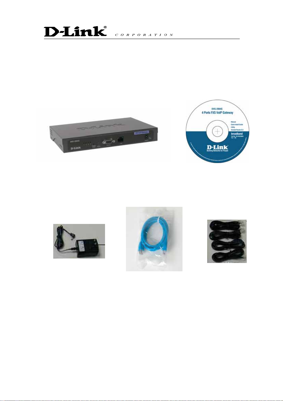
1.2 Unpacking list
Please check enclosed product and its accessories before installation. (Please refer to the item number).
This is a pre-release version only and will be updated for official release.
VoIP Gateway (Model: DVG-2004S)
Ethernet Cable (1.6 metre)Power Adaptor (12V DC) RJ-11
CD
3
Page 7
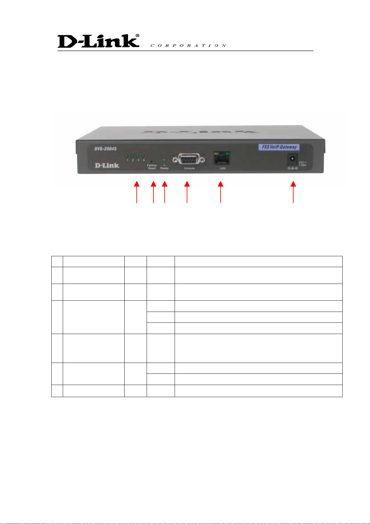
1.3 G/W interface
G/W front view (Please refer to the following number).
(2) (3) (4)
The LED lights show the status of TA where list on the front panel of G/W.
No. Label Color Display Status
(1) FXS 1-4 Green On The phone line is active
(2) Reset Reset the G/W
(3) Ready Green
(4) CONSOLE PORT
(5) LAN (10/100M) Amber
(6) PWR A power supply cable is inserted
(1)
LED display list
On Power on
Flash System is rebooting
Off Power off
It is a RS-232 port for system managements.
It connects with the serial port of a personal computer by the
RS-232 cable
On Network connected
Flash Packet is through this port
(5)
(6)
4
Page 8
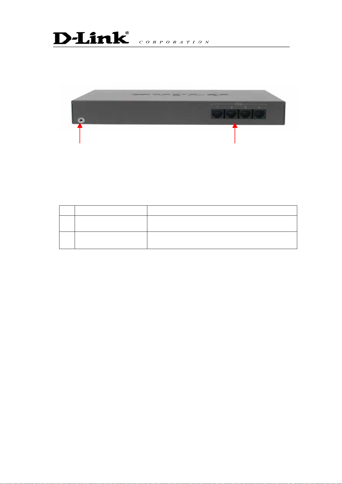
TA rear view (Please refer to the following number).
Please refer to the following table that indicates the description of each port. Please connect the required
cable/line according to this table
No. Port Description
(1) (2)
(1) Grounding cable The plug of the grounding cable is carried out.
FXS 1〜4
(2)
It connects with telephone RJ-11 analog line.
5
Page 9

2. Installation
2.1 Installation environment
Please confirm the environment for installing G/W.
Power supply
The following conditions are fulfilled and it checks that the power supply of this equipment can use
near the installation place.
Voltage:Input AC 100~240V 50~60Hz, output DC12V, 1.25A
Power supply frequency:50Hz±2Hz/60 Hz±2Hz
Grounding
It checks that the 1st-sort ground of 10Ω or less of grounding resistance which connects FG earth
wire can use near the installation place.
Temperature, Humidity.
An installation place is an airy even place and it checks fulfilling the following environmental
conditions of operation moreover. Temperature, humidity.
Temperature range:-40°C〜+70°C
Relative humidity:10%〜90%(Non-condensing)
2.2 Connection of power supply cable and grounding cable
FG grounding cable is connected.
The tip of FG grounding cable is connected to FG terminal in this equipment back.
Another tip of FG grounding cable is connected to the 1st-sort ground.
A power supply cable is connected.
A plug is inserted in a power supply wall socket.
6
Page 10
3. Utility Configuration
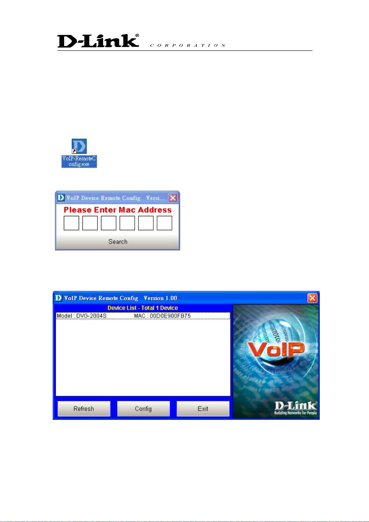
3.1 Setup with VoIP-Remoteconfig
Once you finish installing, a new icon is created on your desktop.
Double click this icon.
Click on the empty field and enter the MAC address (printed on the back of your TA). If you cannot find
the MAC address, click “Search” to view all the available MAC addresses in the LAN. You will see the
following window.
Device list: List all the devices installed in the LAN.
This window contains 3 buttons -
Refresh: Refresh the information on the Device List.
Config: Configure the device.
7
Page 11
Exit: Exit VoIP Device Remote Config.
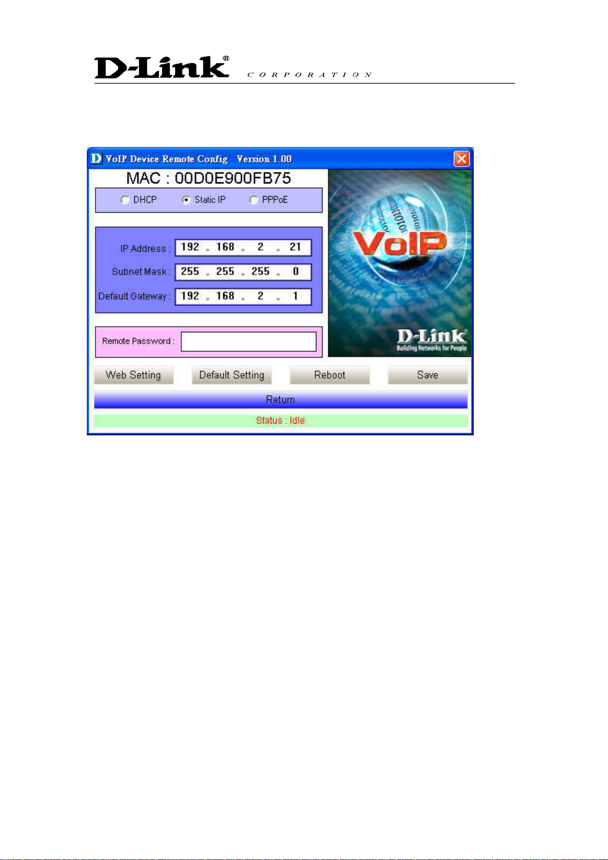
After you click the Config button, you will see the following window.
There are 3 ways to setup the IP address: DHCP, PPPoE, and Static IP. Select your Network
settings. These are the most common setup:
For LAN, please choose Static IP
For xDSL, please chose PPPoE
For cable internet, please choose DHCP
For other Network setup, please consult your Network Administrator.
Before you can save these settings, the TA will ask you to enter the password on the Remote
Password field.
Remote Password: Default password is “1234”. After you enter the correct password, you may
select “Default Setting”, “Reboot” or “Save”.
Web Setting: Link user directly to the web setting interface.
Default setting: Restore to factory default settings.
Reboot: Restart the system.
Save: Save any changes and restart the system.
Status: Displays the device’s current status (Idle, Rebooting etc).
Return: Return to the “Device List” window.
8
Page 12
4. WEB Configuration
4.1 Set up TA Using Web Browser
Load a web browser, i.e., Internet Explorer or Netscape Navigator.
In the URL field, type in the ip address followed by :9999 and press ENTER.
(example: http://210.80.83.197:9999
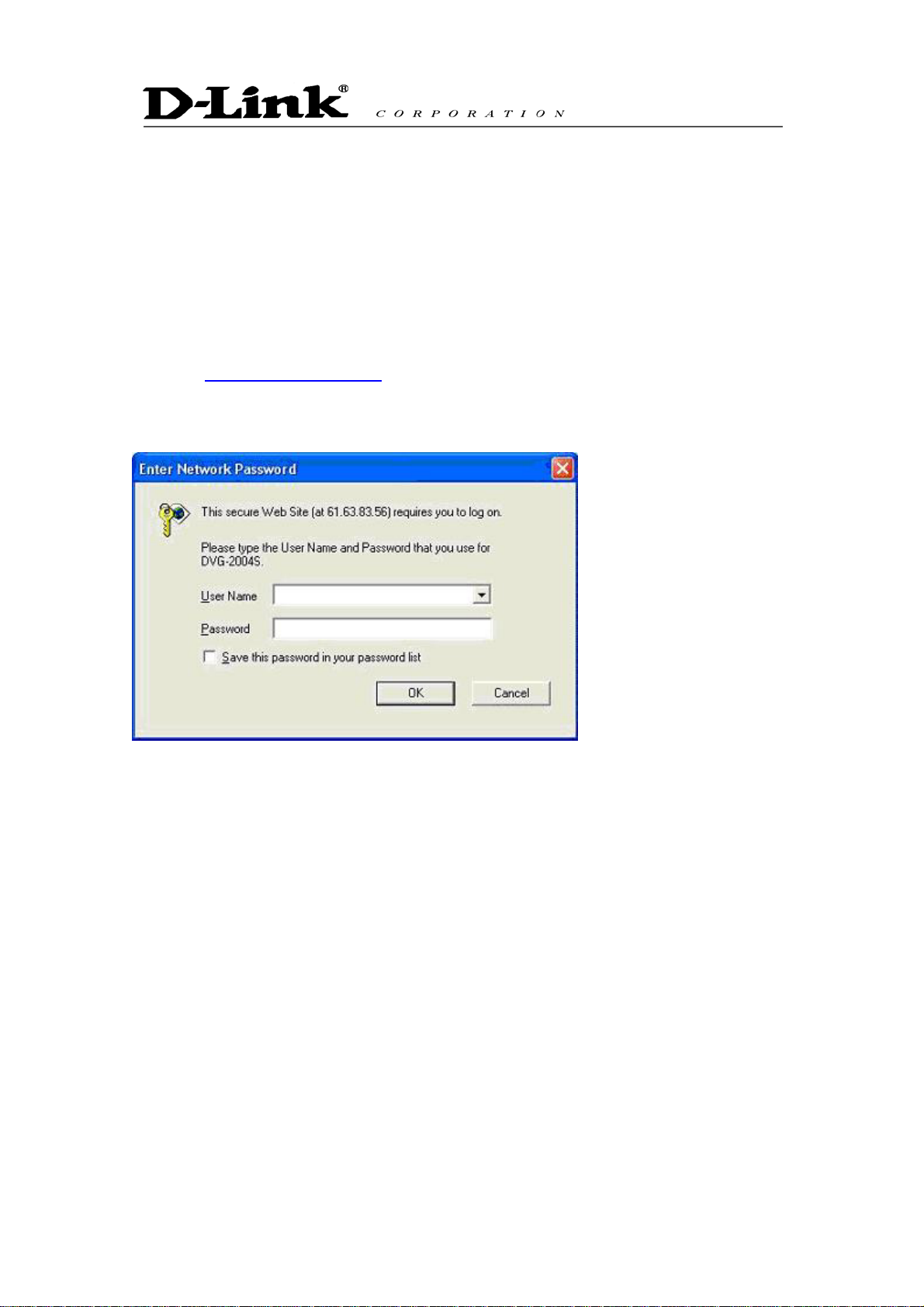
You may access the configuration menu as an Administrator or as a User.
Administrator mode
Administrator can access all the menus, including Management, User Setting, Dial Plan,
Administrator Setting and Call Log.
)
(Default admin username: admin / Password: admin)
To access the adapter as an administrator, use admin for username and admin for password.
9
Page 13

User mode
You can access Management, User Setting, and Dial Plan.
(Default username: user / Password: user)
To access the adapter as user, use user for username and user for password.
Version Information and Reboot Function:
Firmware Version
MAC Address
System Reboot
Hardware version
Media Access Control Address of the terminal adapter
Reboot the terminal adapter.
10
Page 14

4.2 Management
4.2.1 General Setting
Click on Management and select General Setting. The following window will display on the screen.
ID and Password
ID
Password
Date / Time Setup
NTP Time Server
Manual Time Setting
NTP Server IP
Login name (default is admin).
For security reasons please change the password
(default is admin) often.
Protocol used to help match your system clock with an
accurate time source. For example atomic clock or a
server.
Set up the time manually.
NTP server IP address.
11
Page 15

Time Zone
Remote Monitor Server Setup
Syslog Server IP
IPConfig Password
NOTE: Only alphabet and numbers can be used.
Click [Submit] to confirm the change. Click [Cancel] to restore the previous value.
Choose your time zone. Default setting is
‘GMT+09:00’Osaka, Tokyo, Seoul’.Please check the
daylight saving box if your region has daylight saving.
System log server IP address.
Remote password to modify Network Setting from
“VoIP software”. Default password is “1234”. You may
obtain this software from your supplier.
4.2.2 Firmware Update
Select Firmware Update from the Management menu.
NOTE: You must setup firmware update menu to enable the terminal adapter to automatically download
and update firmware. Do not modify these settings unless you are the network administrator, the
technician or the distributor.
TFTP Server IP
Firmware Filename
Server IP address in which the updated firmware can be
downloaded.
TFTP firmware filename.
12
Page 16

Mode
Click [Update] to begin the firmware update process.
File Transmission mode.
4.2.3 Line Status
Select Line Status from the Management menu.
This window displays the Port and Loop Line Type (IDLE, NG and etc.)
Click Refresh Status to retrieve the terminal adapter status.
4.3 User Setting
4.3.1 Network Setting
Select Network setting from the Management menu.
There are 3 ways to setup the IP address: DHCP, PPPoE, and Static IP. Please select one of the
following depending on your network setup. For example, if you use ADSL, please select PPPoE. For
cable internet users, select DHCP. If your ISP provide you with all the WAN addresses, select static IP
and enter the IP address provided.
DHCP (Dynamic Host Configuration Protocol)
When you select DHCP, IP address is obtained automatically from the DHCP server. The terminal
adapter will not work properly if there is no DHCP server in your LAN.
13
Page 17

DNS Server
Domain Name
Telnet
NAT IP Address
Assigned DNS server IP address
The unique name that identifies the internet site
Protocol for remote computing on the internet
NAT (Network Address Translation) serves three purposes:
1. Provides security by hiding internal IP addresses.
Acts like firewall.
2. Enables a company to access internal IP addresses.
Internal IP addresses that are only available within the
company will not conflict with public IP.
3. Allows a company to combine multiple ISDN
connections into a single internet connection.
DHCP Server
IP Pool
Lease Time
Enable/Disable DHCP server. Another method to enable
DHCP is by entering ***886# from the phone keypad
Default IP range is: 16 ~ 128
Lease time from DHCP server. Default lease time is 259200
seconds (3 days).
14
Page 18

Click [Submit] to confirm the change. Click [Cancel] to restore the previous value.
PPPoE (Point-to-Point Protocol Over Ethernet)
Select PPPoE if you use ADSL. PPPoE ID and password are provided by your ISP.
DNS Server
Domain Name
Telnet
NAT IP Address
Assigned DNS server IP address.
The unique name that identifies the internet site.
Protocol for remote computing on the internet.
NAT (Network Address Translation) serves three purposes
1. Provides security by hiding internal IP addresses.
Acts like a firewall.
2. Enables a company to access internal IP addresses.
Internal IP addresses that are only available within the
company will not conflict with public IP.
3. Allows a company to combine multiple ISDN
connections into a single internet connection.
DHCP Server
IP Pool
Enable/Disable DHCP server. Another method to enable
DHCP is by entering ***886# from the phone keypad.
Default IP range is: 16 ~ 128
15
Page 19

Lease Time
Click [Submit] to confirm the change. Click [Cancel] to restore the previous value.
Static IP
Select static IP and enter the IP address provided if your ISP provide you with all the WAN addresses.
Lease time from DHCP server. Default is 259200 seconds.
DNS Server
Domain Name
Telnet
NAT IP Address
Assigned DNS server IP address.
The unique name that identifies the internet site.
Protocol for remote computing on the internet.
NAT (Network Address Translation) serves three purposes:
1. Provides security by hiding internal IP addresses. Acts
like firewall.
2. Enables a company to access internal IP addresses.
Internal IP addresses that are only available within the
company will not conflict with public IP.
3. Allows a company to combine multiple ISDN
connections into a single internet connection.
DHCP Server
Enable/Disable DHCP server. Another method to enable DHCP
is entering ***886# from the phone keypad.
16
Page 20

IP Pool
Lease Time
Click [Submit] to confirm the change. Click [Cancel] to restore the previous value.
Default IP range is: 16 ~ 128
Legal use the given IP during that time. Default is 259200s.
4.3.2 Call Setting
17
Page 21

Call Waiting
Anonymous Call
Anonymous Reject
Call Forward
Call waiting ensures that all important calls get to you. For
example, if you are on the phone when another person tries to
call you, an audible beep will inform you that someone is waiting
on the other line. You can decide whether or not you want to put
the current caller on hold and take the incoming call.
This is an optional service that lets you decide whether or not
you want to block your phone number from displaying on the
receiver’s phone.
Anonymous Caller Rejection is a service that rejects callers with
anonymous name/phone number. However, you will still receive
calls users with anonymous telephone number.
Call forward allows you to forward incoming calls to a
pre-designated telephone number. It includes No Answer, Busy
and Unconditional. Please enter IP address, URI or number
registered with SIP server.
18
Page 22

Incoming No Answer Timer
Click [Submit] to confirm the change. Click [Cancel] to restore the previous value.
The time duration for the next action if no one answers the
phone. The default is 20 seconds.
4.4 Dialing Plan
There are 4 options in this pull down menu, General Setting, Local Setting, PSTN Seting, and URI
Phone Book.
4.4.1 General Setting
Select General Setting from the Dialing Plan menu. The following window will load.
LATT (Local Address Translation Table) / Dialing through SIP Server
LATT
Dialing through SIP
Server
Inter-digit Timeout
First Digit timeout
When you dial any number, TA will look for the number in Local
Setting (Refer to sec. 4.4.2 Local Setting for details)
SIP server will define all the calling rules. You can skip sec.
4.4.2 Local Setting and sec. 4.4.4 URI Phone Book.
If no other number is being dialed within this interval, the
terminal adapter will terminate the call.
If you pick up the phone without dialing any number within this
period of time, the tone will change to busy tone.
19
Page 23

Send Sign
Switch Key:
URI Phone Book:
Click [Submit] to confirm the change. Click [Cancel] to restore the previous value.
Setting a button as a default send button. When this button is
pressed, the number will dial immediately. Default button is #
key in the phone pad.
Setting a button or a set of buttons to switch between LATT
mode and SIP server mode. Default button is ## key on the
phone pad.
URI (Uniform Resource Identifier Phone Book) lets you define a
button or a set of buttons to link to a specific number defined in
URI Phone Book (refer to sec. 4.4.4 for details about URI
Phone Book). Default button set is *# key on the phone pad.
You can enter from *#1 to *#10 dial key to call the recorded URI
numbers.
4.4.2 Local Setting
Select Local Setting from the Dialing Plan menu.
Local dialing plan allows users to dial out to a VoIP Device using a pre-defined number. Users do not
have to change their dialing habit.
Prefix
Numbers defined in this field will be inserted at the
beginning of the dialing pattern. Maximum input length is
6 digits.
20
Page 24

Min Digit
Max Digit
Delete Digit
Add Prefix
Remote IP
Remote PORT
Minimum digit user can key in.
Maximum digit user can key in.
Number of digit defined in this field will be removed from
the dialing pattern. For example, lets assume the phone
number 81352109378. If delete digit is 2 then the dialed
number is 352109378. First 2 digits are removed.
Maximum delete digit is 3 digits.
Numbers in this field are added at the beginning of the
dialing pattern. For example, if 001 is in this field, the
number dialed is 001+the rest of the numbers. The input
length is limited to 6 digits.
Remote side Gateway IP addresses.
Remote side port number to use. The input length is
limited to 5 digits.
Memo
[Insert]
[Add]
[Delete]
[Change]
Memo field for user to make remark. The input length is
limited to 18 characters.
Insert a record where the current record is located
(Current record is marked as different color).
Add a new record to the bottom of the list.
Delete a record.
Modify the value of the record in the LATT.
Click [Submit] to confirm the change. Click [Cancel] to restore the previous value
4.4.3 URI Phone Book
Select URI Phone Book from the Dialing Plan menu.
User can pre-define the other TA’s URI. You may use URI Phone Book to add, edit and save the URI
records.
21
Page 25

Click [Submit] to confirm the change. Click [Cancel] to restore the previous value.
22
Page 26

4.5 Administrator Setting
4.5.1 SIP Setting
Select SIP Setting from the Administrator Setting menu.
23
Page 27

Display Name
Request URI
Login Name
Password
Port No.
Register Server IP Address
Register Server IP Address
Port
Outbound Proxy
Name displayed on the LCD for the caller.
URI displayed on the LCD for the caller.
User name to log in the SIP server.
User password to log in to the SIP server.
SIP port number of TA.
SIP Register Server IP address.
Port number of SIP Register Server.
Outbound Proxy server IP address.
Outbound Proxy Port
Backup Proxy
Backup Proxy Port
Register Expires
Start Media Port
Session Timer
Session Type
Session Refresher
Port number of Outbound Proxy Server.
Backup Proxy Server IP address.
Port number of Backup Proxy Server.
.
Timer for registration.
Port number for initial of sending RTP packet.
The time interval in which the phone periodically refresh SIP
sessions by sending repeated INVITE or Update request,
depending on session type.
Select Re-invite or Update for this function.
Select UAC (User agent client) or UAS (User agent server) for this
Pre-Ack
function.
Ensure the correct signal transmission. Select enable or disable.
24
Page 28

UDP Timeout
UDP Retry Tim e
UPnP
STUN IP Address
Timeout time of an INVITE request (it is set as 100 - 3000 msec).
The number of times to send INVITE requests (Available interval is
0 - 6 times).
Universal Plug and Play. Enable or disable this function.
Simple Traversal of UDP through NATs (Network Address
Translation). Enter the Stun IP Address.
4.5.2 Voice Setting
Select Voice Setting from the Administrator Setting menu.
Default Codec
G.729A, G.711 uLaw,
G.711 aLaw
DTMF Method
VAD
Default voice codec.
A RTP packet is sent out every specified time cycle.
Please choose Out Band, In Band (default) or SIP Info for DTMF
method.
Enable / disable Voice Activity Detector.
25
Page 29

CNG
Jitter Buffer Size
TOS Field
G.168 Echo Cancellation
Click [Submit] to confirm the change. Click [Cancel] to restore the previous value.
Enable / disable Comfort Noise Generator.
The size of the buffer which absorbs the attainment delay
fluctuation of a RTP packet specified time (ms).
Service type.
Enable / Disable G.168 echo cancellation.
4.5.3 Port Setting
Select Port Setting from the Administrator Setting menu.
Setting the phone number assigned to each channel, such as FXS and FXO.
Card 0_[ FXS ] The number assigned to FXS channel
Disable If this check box is turned ON, dispatch/arrival will become
invalid
Loop Service Line
Type
There is an option, like an analog, a number display, being
dial-in, modem being dial-in, and it is intact (intact : state where
26
Page 30

the port belonging to this group is not used with FXO and FXS,
either).
Dial-In Direct Digits
FXS Reverse A specific signal indicating the status of the
Tone Setting Adjust the tone frequency according to each
Line Detect On Hook Detect, Off Hook Detect, Hook Flash
Caller ID Setup by area code.
Voice TX Gain
(-48db ~
24db)
Voice RX Gain
(-48db ~
24db)
DID set as PBX is set up by 0-4. If 0 is chosen, it will be set as
4. Usually, a setup of PBX is followed
conversation.
country.
Detect: On Hook, Off Hook, and Hook timing
setting. Line detect basically detects the current
phone status.
Sets a specific sound intensity for transmitting
sound.
Sets a specific sound intensity for receiving
sound.
Click [Submit] to confirm the change. Click [Cancel] to restore the previous value.
4.5.4 Restore Setting
Select Restore Setting from the Administrator Setting menu.
When you select “Restore” you will see the following display:
To restore all the parameters back to factory default setting, click “Default Setting?”. However dialing
plan and IP address will remain the same.
27
Page 31

4.6 Call Log
Call log keeps a list of your calls. There are four submenus: Even Log, Call Detail Record and Sys
Log.
4.6.1 Event Log
Select Event Log from the Call Log menu.
The status of the call can be checked from Event Log.
4.6.2 Call Detail Record
Select Call Detail Record from the Call Log menu.
When you click the [Call Detail Record] you will see the following widow:
28
Page 32

4.6.3 Sys Log
Select Sys Log from the Call Log menu.
All the operations performed by the terminal adapter are listed on SysLog.
4.7 System Reboot
Reboot the system if you update any information. Please click the hyperlink character System Reboot
on the bottom left of the menu to reboot.
29
Page 33

5. Telnet
Telnet configuration is designed for advanced users, Network Administrators or System Engineers. Any
improper use will affect the performance of the terminal adapter.
TA reserves port 4748 for telnet use only.
At command prompt type in <telnet IP address> : 4649. For example, telnet 63.81.83.173:4649 then
press [Enter]. System will ask user to input username and password (default username and password
is admin)
These are available commands for Telnet configuration:
config {<adm>|<net>|<dialplan>|<sip>|<voice>|<tel>|<mis>}
quit Quit the shell
reboot Reboot the system
show Show the setup info. Same as “?”
write Write the data which have been modified
xdef Restore to default values manufacturer
portstatus Port status log
logout Shell logout
For network administrator configuration:
config adm
exit Exit to previous folder
name Gateway name
pw Password for gateway
sntp Setup SNTP IP
tz Time zone configuration
ver Firmware Version
uyear Set year
umonth Set month
uday Set day
uhour Set hour
uminute Set minute
usecond Set seconds
tscheck Time server check
syslog System log server
snmp SNMP server
30
Page 34

snmppo SNMP server port
snmpti SNMP trap interval
For network configuration:
config net
dhcp Setup HDCP
dns DNS Server IP
domain Domain Name
ipconfig Config IP, Subnet, Router
mac MAC address
pppoe Config PPPoE
For dial plan configuration:
dp Dial plan base info configuration
dpl Dial plan Local setup
dpr Dial plan Remote setup
dpp Dial plan PSTN setup
For sip configuration:
sip SIP display name
sipn SIP login name
spipw SIP password
sippo SIP port
sipsvr SIP server
sipsvrpo SIP server port
udpto UDP time out
udprt UDP retry time
stun Stun server
sipf SIP request_URI
For voice configuration:
codec Setup default codec
g711a G.711_alaw packet size
g711u G.711_ulaw packet size
g729a G729a packet size
jbuf Jitter buffer size
silence Setup send silence
tos Setup tos value into IP header
31
Page 35

vadcng Setup VAD & CNG
echo Echo cancellation
For telephone configuration:
telno Setup telephone number
gainrxv The voice gain of rx
gaintxv The voice gain of tx
fxogainrxv The FXO voice gain of rx (This is for FXO port use ONLY)
fxogaintxv The FXO voice gain of tx (This is for FXO port use ONLY)
For other configuration:
ctl Call trace log
ping To verify that the HOST is still active
For best G/W performance, we strongly recommend users to use web UI to do the configuration. Telnet
command is for experienced system users.
32
Page 36

6. Feature Summary
Item Specification
Protocol IETF SIP (RFC 3261)
Supplementary service Call Hold, Call Transfer, Call Waiting, Call Forward,
In Band DTMF
Codec 8K of G.729a
64K PCM,G.711aLaw/G.711uLaw
5.3K/6.3K of G.723.1(optional)
Network Interface 10/100BaseT x 1
Phone Interface (FXS) RJ-11 x 4
Voice Quality VAD (Voice Activity Detection)
CNG (Comfort Noise Generation)
AEC (Acoustic Echo Cancellation) G.168
QoS ToS field identify
Tone DTMF / CPT (Call Progress Tone) generation
Ring tone
Ring back tone
Dial tone
Busy tone
Caller ID For FSK, DTMF& Bell core
IP Assign Static IP/DHCP/PPPoE
TCP/IP IP/TCP/UDP/DHCP/RTP/RTCP/ICMP/HTTP/NTP/TFTP/DNS
Console
Configuration
Upgrade
Power Input AC 100-240V AC, 50/60 Hz
Telnet
Web browser
Firmware upgrade through network by TFTP.
Output 12V DC,1.25A
Operation Temp. 0° C to 40° C
Humidity 10% to 90 % (Non-condensing)
33
Page 37

Appendix A Troubleshooting and Maintenance
Troubleshooting
Please follow the setup direction described in 1
your G/W still does not work, follow the instructions provided below to troubleshooting.
Step 1 – Unplug the power and wait for 3 seconds before reconnecting the power.
Step 2 – After the power is turned on, start checking if all the cable connections are in place. Make
sure your TA WAN port is connected to your XDSL/Cable.
Step 3 – Try to ping your G/W’s IP address described in section 3.2. You will be able to determine
whether the problem is from the network problem or terminal adapter.
Step 4 – If it is network problem, please contact your ISP or your network administrator and have
them resolve this.
st
section after you purchase the terminal adaptor. If
Step 5 – If problems still exist, please contact your authorized G/W distributor. Before you contact
them, please have your module and series number ready, so the issue can be resolved faster.
Maintenance
We strongly recommend users to operate the terminal adaptor under a safe environment. These are
few tips that you can do to maintain your G/W:
Do not block the airflow entrance of the G/W to avoid the potential over heating problem.
Do not put heavy objects on top of the G/W.
Periodically clean up the dust near the G/W operation area. Do not use a wet material to
clean up the G/W.
If you are not using the connectors (2 RJ11 and 2 RJ 45). Please seal them up to avoid
getting dust into the G/W.
This device complies with Part 15 of the FCC Rules.
Operation is subject to the following two condition s:
(1) this device may not cause harmful interference, and
(2) this device must accept any interference received,
including interference that may cause undesired operation.
34
 Loading...