

Page 1

DVC-1100
i2eye
TM
(Patent Pending)
Wireless Broadband VideoPhone
Manual
Building Networks for People
v1.03
Page 2

Page 3

Contents
Introduction ......................................................................................................3
Package Contents ...........................................................................................4
System Requirements ......................................................................................4
Features & Benefits ......................................................................................... 5
Connections ....................................................................................................5
LEDs................................................................................................................6
Getting Started ................................................................................................. 7
Using the Remote Control ................................................................................ 7
Using the Onscreen Keyboard ......................................................................... 9
Using the Setup Wizard .................................................................................10
Using a Telephone with the DVC-1100 .......................................................... 17
Using the DVC-1100 ...................................................................................... 18
Using the Configuration Menu ....................................................................... 27
Using the DVC-1100 with D-Link Routers ...................................................... 47
Using the DVC-1100 with Routers, Gateways or Modems ............................. 48
Troubleshooting ............................................................................................. 53
Frequently Asked Questions .......................................................................... 62
Glossary of Terms .......................................................................................... 65
Technical Specifications.................................................................................69
List of Country Codes .................................................................................... 71
Contacting Technical Support ........................................................................73
Warranty and Registration .............................................................................74
Page 4

Introduction
Imagine having high-quality, low-cost videoconferencing from a standalone, easy
to use communication appliance that supports your existing wireless network.
The D-Link i2eye
accomplishes this. D-Link i2eye introduces the world of videoconferencing over
the Internet, to bring you and your family, friends and colleagues together, in
real time, anytime! The previously complicated process of conducting a video
conference is simplified with the i2eye DVC-1100. Since the DVC-1100 is a
standalone device, you do not need a computer to video conference over the
Internet. The i2eye DVC-1100 is such a revolutionary leap in technology that
D-Link calls it a VideoPhone. Connect a television for viewing, an optional
standard telephone for privacy, connect wirelessly to your broadband Internet
connection and you are ready to use your i2eye DVC-1100 Wireless VideoPhone.
Using advanced video compression technology, the i2eye DVC-1100 Wireless
VideoPhone maximizes the image and audio quality within the available
bandwidth. It is an ideal solution for consumers and small businesses with highspeed broadband Internet access. There is no delay in waiting for a PC to boot
up before using your i2eye
have to be a computer expert. Using the Internet, in place of conventional dialup phone lines, maximizes your existing broadband investment. The remote
control included with the i2eye DVC-1100 makes it easy to answer an incoming
videoconference call or dial out to start your own videoconference. The built-in
caller ID provides privacy protection. You know who is calling before you answer
and the audio or video can be turned off whenever desired.
TM
DVC-1100 Wireless Broadband VideoPhone
DVC-1100 Wireless VideoPhone, and you don’t
This manual provides the instructions to install and use your D-Link i2eye
DVC-1100 Wireless Broadband VideoPhone and will help to make your Wireless
VideoPhone experience go as smoothly as possible.
Page 5

Package Contents
D-Link i2eye
Power Adapter
Instruction Manual
Quick Installation Guide
Remote Control with Batteries
Standard Composite RCA Audio / Video Cable
Cat 5 RJ-45 Ethernet Cable
Wireless Antenna
Note: Using a power supply with a different voltage than the one included with
the DVC-1100 will cause damage and void the warranty for this product.
TM
DVC-1100 Wireless Broadband VideoPhone
System Requirements
Connection to broadband Internet (Cable modem, DSL modem, wireless network
or Ethernet network)
Television with standard composite audio and video inputs (white and yellow RCA
jacks) or with a RF modulator to enable a TV without AV jacks to be connected
using the antenna terminal
Optional (but recommended): Standard telephone attached directly to the
DVC-1100
Optional: An external microphone can be connected to the pink Mic port on the
rear of the device for improved audio quality when a group of people are involved in
the DVC-1100 call
Optional: You can connect the DVC-1100 to a PC equipped with a videocapture
device that allows input of standard composite video (using RCA Jacks)
4
Page 6
Features & Benefits
Standalone operation - No computer needed
Supports enhanced 802.11b wireless networks up to 22 Mbps
Uses broadband cable/DSL or network connections for high-quality video
H.323 Internet videoconferencing standard compliant
Uses the D-Link Directory Service for ease of use dialing
Easy to use
Easy Setup Wizard
Picture-in-Picture view or full-screen view
Remote control included
Flexible calling formats for worldwide use
Speed Dialing
Built-in Caller ID
Answer incoming calls using telephone or remote control
Auto mapping of IP Address
Advanced video and audio privacy protection
Video and / or audio mute
Adjustable tilt and focus lens
Up to 30 frames per second
High quality 352 x 288 resolution
Automatic detection of system upgrades
1 Year Warranty
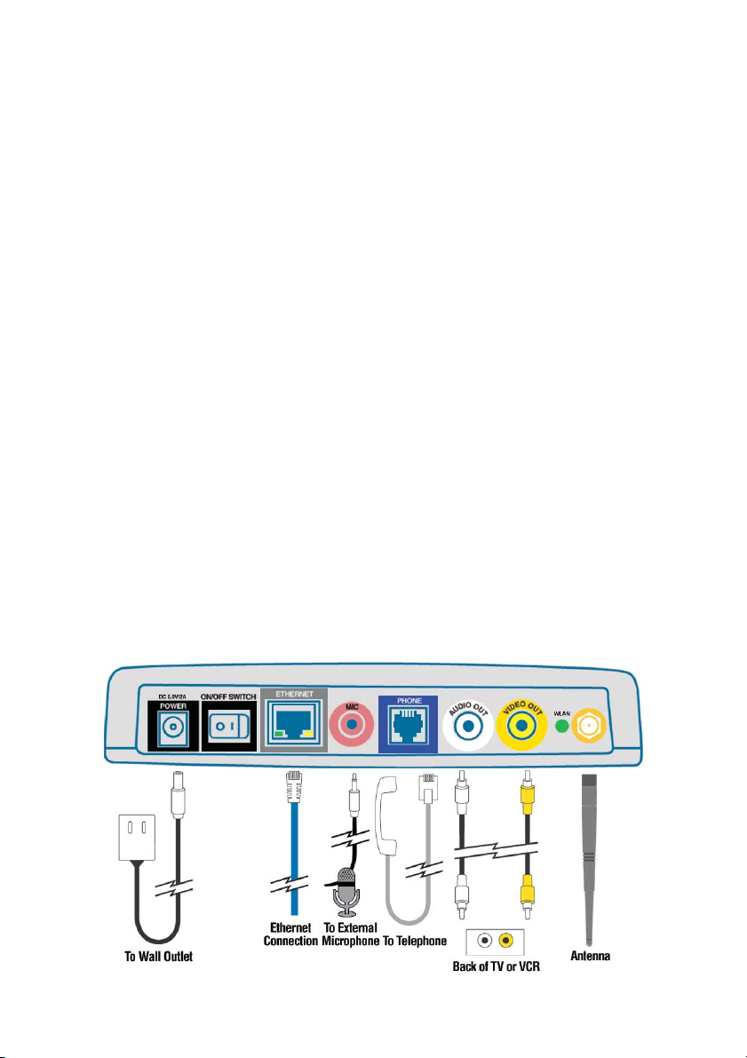
Connections
The connection diagram above also appears on the bottom of
the DVC-1100 to assist you in setting up your VideoPhone.
5
Page 7
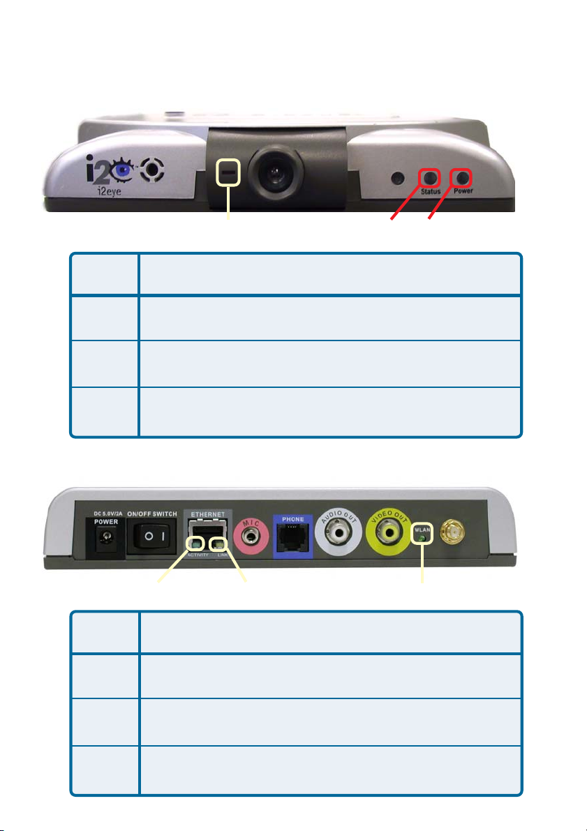
LEDs
LED stands for Light-Emitting Diode. The i2eye
following LEDs for monitoring its operation.
Call Monitor
LED
Power
Status
Call
Monitor
A green light indicates the DVC-1100 is ON
This LED turns on briefly at power up. It is then off during
normal operation
Steady red light indicates video is being sent and a call is in
progress
Front LED Location
TM
DVC-1100 has the
Status
Power
LED
Activity
Link
Status
WLAN
Link StatusActivity
WLAN
Back LED Location and Activity
Steady or blinking green light indicates the
DVC-1100 is transmitting data
Steady yellow light indicates the network connection is good
Wireless LAN, green light indicates activity on the wireless
network
6
Page 8

Getting Started
BEFORE YOU BEGIN!
Read the section on using the DVC-1100 with routers, gateways or broadband
modems starting on page 47 in this manual if you are using the DVC-1100
VideoPhone with a router, gateway or broadband modem.
The DVC-1100 needs to be setup before use. You can use the Quick
Installation Guide (included with the DVC-1100) to perform the hardware
installation. Each cable (video, audio, Ethernet and AC power) supplied for the
DVC-1100 has a different color on the end that connects to the DVC-1100.
Plug the cables into the matching color coded connector on the back of DVC-
1100. You can also plug an optional telephone and/or external microphone
into the DVC-1100. If you are using the DVC-1100 wirelessly, screw the included antenna into the antenna connector on the back of the DVC-1100. To
help you with these connections, there is an illustration on the bottom of the
unit.
There is an easy to use Setup Wizard built-in to the DVC-1100 to accomplish
the setup. You will need to enter your name, a videophone number, wireless
network settings and your Internet connection information in order to use your
VideoPhone.
Using the Remote Control
By using the remote control included with the DVC-1100, you can answer an
incoming call, start a call by dialing the other videophone’s number or select a
number to call from the Speed Dial list.
Information for the Setup Wizard is entered by using the remote control. The
remote is used to enter numbers, letters, special characters and to make selections from an on-screen keyboard. The on-screen keyboard is activated by pressing ENTER on the remote control whenever the on-screen cursor is located in a
field where text is required.
You will use the arrow keys on the remote control along with the ENTER,
CANCEL and number keys to enter information in the Setup Wizard screens.
Where a numeric input is required, such as a telephone number or IP address,
enter it directly by pressing the number keys. The * (asterisk--sometimes called
a “star” key) is used to enter a “.” (period also called a “dot”.)
When you are entering numbers or letters, the left arrow key performs a backspace, deleting the character to the left of the cursor. The following page contains a breakdown of the features of the remote control.
7
Page 9
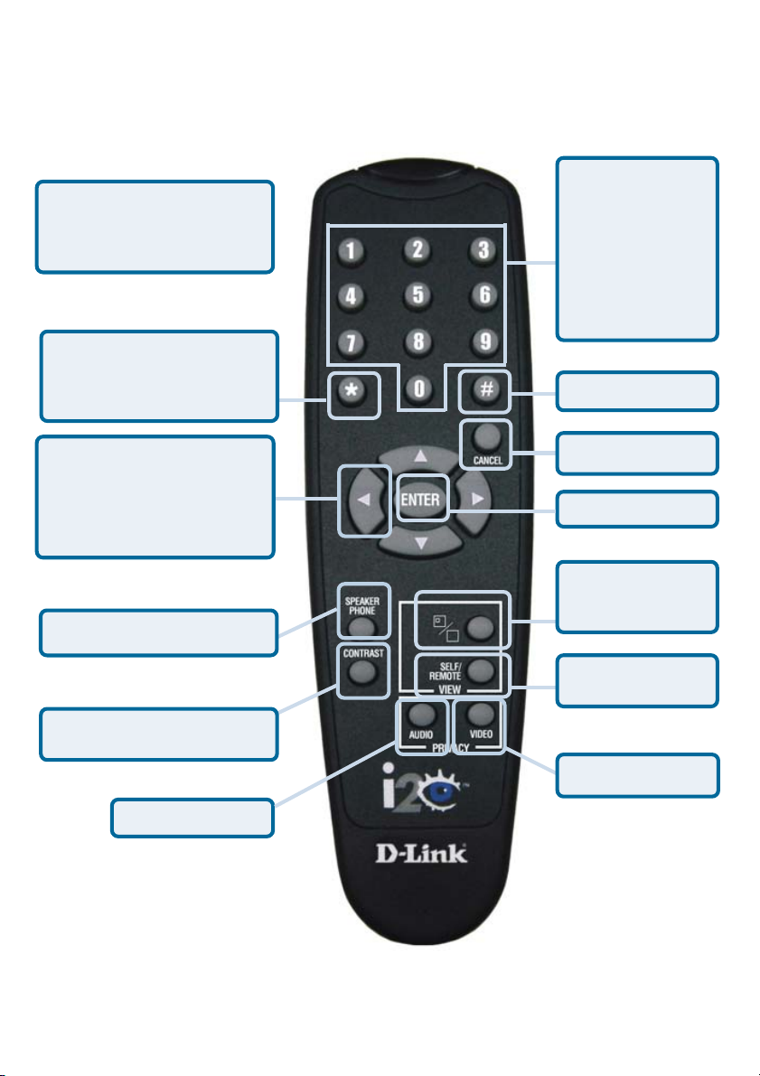
Remote Control Layout
Use the arrow keys along
with the Enter, Cancel and
number keys to enter
information when required.
The * (asterisk--sometimes
called a “star” key) is used
to enter a “.” (period also
called a “dot”.)
When entering alphanumeric
information, the left arrow
key performs a backspace,
deleting the character to the
left of the on-screen cursor.
Speakerphone Mode
When a numeric
input is required,
(e.g., a telephone
number or IP
Address) enter it
directly by pressing the number
keys.
Number sign
Cancel
ENTER key
Full-screen or
Picture-inPicture
Self-view or
Remote View
Adjust Contrast
Mute Audio
i2eyei2eye
i2eye
i2eyei2eye
Mute Video
8
Page 10

Using the On-Screen Keyboard
The DVC-1100 uses a keyboard that appears on-screen to enter text into the
Setup Wizard screens. When the cursor is located in a setup screen that
requires characters to be entered, press the ENTER key to bring up the
on-screen keyboard.
The keyboard will only appear if the cursor is located in an area of the screen
that allows text or numbers to be entered.
To enter text, use the arrow keys on the remote control to move the cursor to the
required character. Press the ENTER key on the remote control to put the
character on the screen. Continue entering characters until you have “typed”
the characters that are needed.
When you are finished entering text and numbers, move the cursor to highlight
OK on the screen and press ENTER; or alternatively you can press the
CANCEL key on the remote to remove the keyboard from the screen, leaving
what you typed on the screen.
The keyboard allows entering any of the following:
• Numbers 0 through 9
• Upper case Letters A through Z and lower case letters a through z
• Special characters: period (.), dash (-), colon (:), at sign (@), space,
backspace (to delete a character to the left), Clear (CLR) to clear the
entered text, comma (,) , and a slash (/)
When you are entering letters, the first letter entered is automatically entered
as UPPER case. The bottom left “arrow” on the screen is a Shift key. This
allows you to change from UPPER to lower case and UPPER case shift lock.
The keyboard features “wraparound” capability. If you press repeatedly on the
left or right arrow keys, the cursor will wraparound to the letter on the opposite
end of the row to speed up moving around the keyboard.
9
Page 11
Using the Setup Wizard
The following descriptions of the Setup Wizard screens will help you understand
the purpose and procedures for providing the required information.
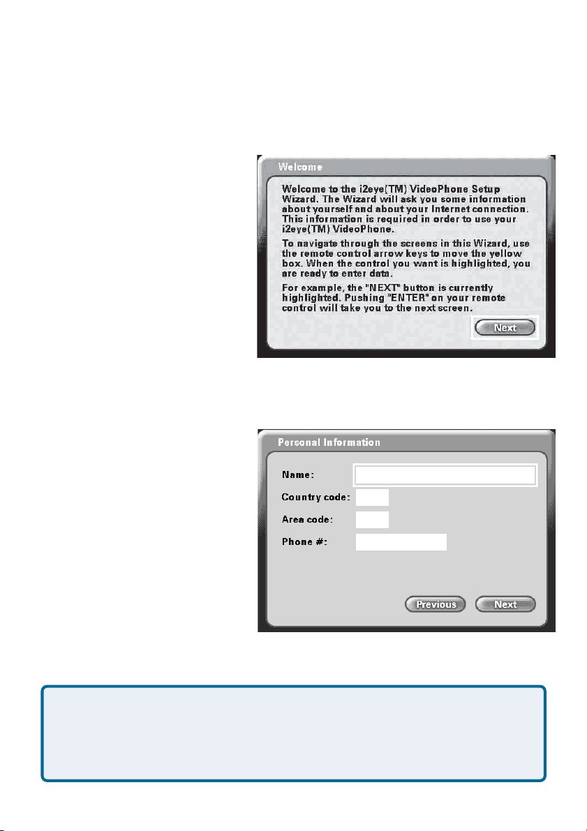
Welcome Screen
The first screen that displays on the
initial startup is the Welcome
Screen. This screen explains what
information is needed to complete
the setup and also explains how to
use the remote control to navigate
through the Setup Wizard. Press
ENTER on the remote control to
continue to the next screen.
Personal Information Screen
Enter your Name, Country code,
Area code and Phone number.
Note: The Country code for the
United States and Canada is “1”.
See the Appendix of the
DVC-1100 manual for Country
codes of other countries.
After the information is entered highlight the NEXT button and press ENTER on the
remote control to continue.
The Phone number you enter is one you create for family, friends and others
to call you over the Internet from another DVC-1100 VideoPhone. You can use
your regular phone number or make up a new one. Only your name will be
displayed at the other end of the video call. Your phone number will not be
visible to anyone else.
10
Page 12
Using the Setup Wizard (continued)
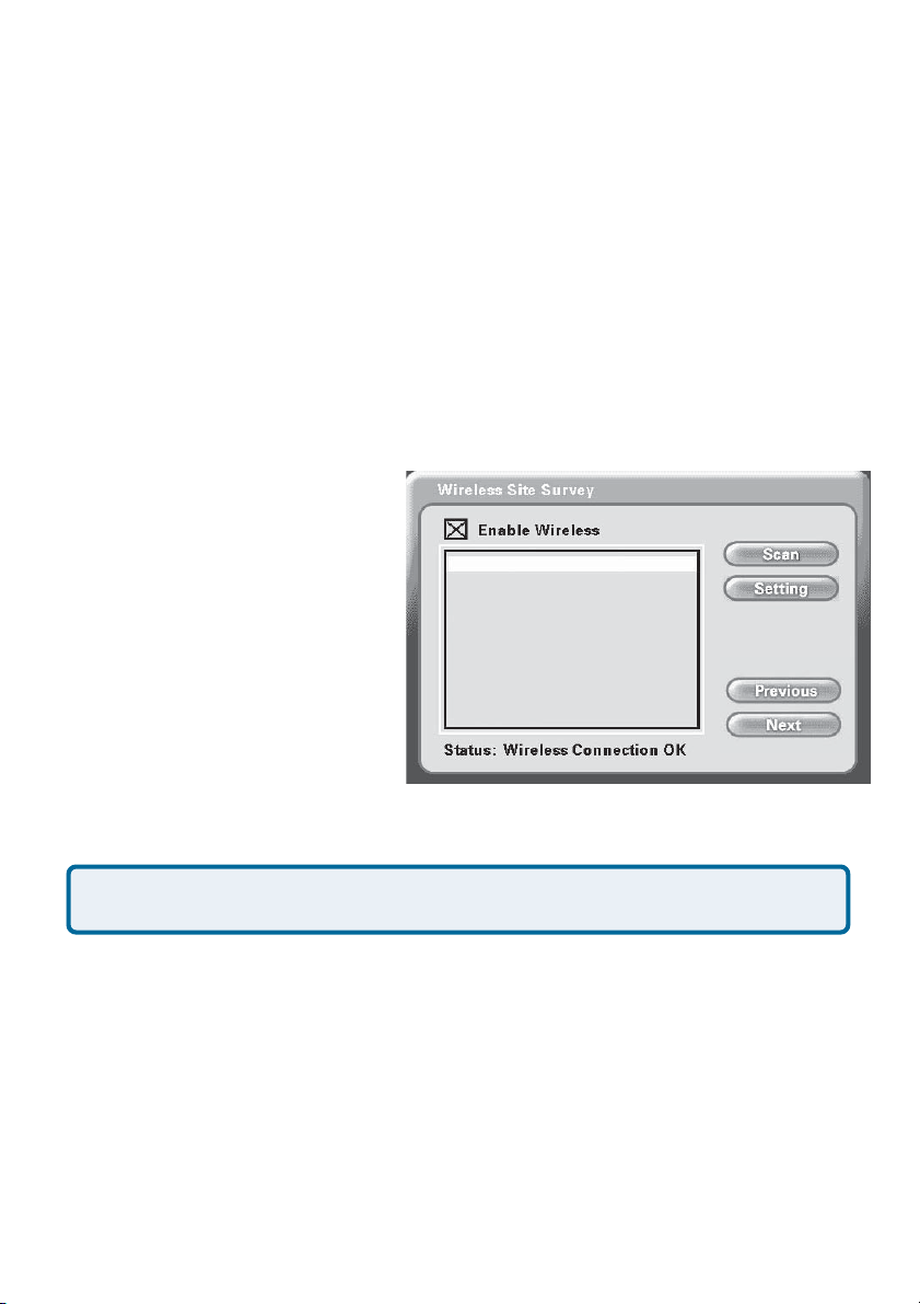
Wireless Site Survey Screen
To use your DVC-1100 wirelessly, it is necessary to find an available wireless
network. The Wireless Site Survey screen makes this simple. Upon starting,
the DVC-1100 performed a “site survey” looking for wireless network devices
the DVC-1100 can connect to. These discovered wireless devices are displayed
by their SSID name on the Wireless Site Survey screen. On a home network,
you may have just one entry. In a business, there may be numerous wireless
devices listed.
The Enable Wireless checkbox is checked by default. This allows the
DVC-1100 to be used wirelessly. If an Ethernet network cable is used instead,
uncheck this checkbox and press Next to continue setup for a wired network as
described on page 15.
To setup for wireless operation,
use the remote control
up/down arrow button to select
the SSID of the device you will
47 i2eye AP
42 Router
36 Default
36 Daisy95
33 Study001
18 Sam’s AP
connect the DVC-1100 to. Typically, this will be a wireless router
or access point.
Press ENTER on the remote to select this SSID and the Wireless Settings
screen will appear (described on the following page).
Note: The number to the left of the SSID indicates the signal strength of
the available access point on the wireless network.
If necessary, you can press the Scan button to perform an updated wireless site
survey scan. The DVC-1100 will update the SSID list.
To access the Wireless Settings screen without selecting a SSID, press the
Settings button.
Press the Next button to proceed to the Wireless Settings screen (if you are
using the DVC-1100 wirelessly) or the Network Address screen (if you are
using an Ethernet cable.)
11
Page 13
Using the Setup Wizard (continued)
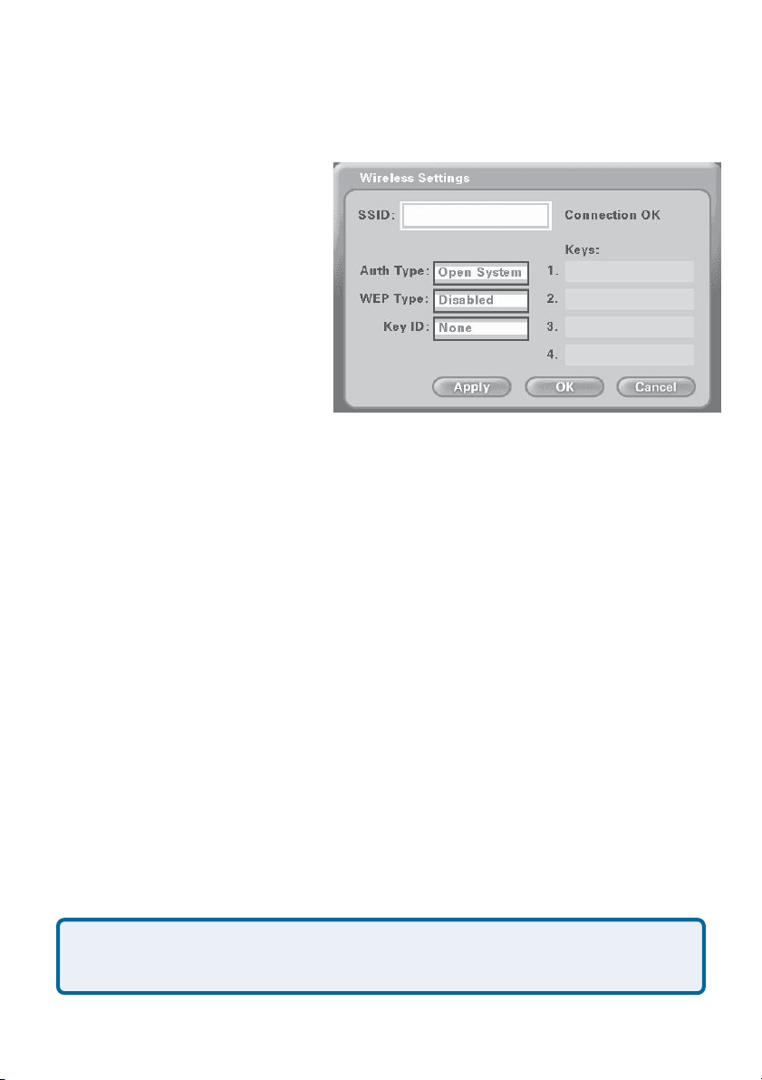
Wireless Settings Screen
The Wireless Settings screen
shows the SSID of the selected
wireless device the DVC-1100
will attach to and allows setting
the DVC-1100 for WEP encryption. The DVC-1100 has WEP
encryption disabled by default.
Encryption will make your wireless network more secure, but
may slow down the network due
to the increased traffic caused by
the encryption.
SSID
The SSID name selected on the Wireless Site Survey screen appears here.
It can be entered/edited using the on-screen keyboard. This may be necessary if a SSID does not appear in the Wireless Site Survey screen because
SSID broadcast feature is disabled on the wireless router or access point.
i2eye AP
Auth Type
Press the down arrow on the remote to select the authentication type (Auth
Type). Select one of the authentication types by pressing Enter. The authentication type must match the type used by the wireless network if encryption is
enabled.
Open System: Communicates the key across the network.
Shared Key: Allows communication only with devices with identical en-
cryption settings.
WEP (Wired Equivalent Privacy) is an industry standard encryption
technology used by 802.11b wireless devices. See “WEP” in the
Glossary for more details.
12
Page 14

Using the Setup Wizard (continued)
Wireless Settings Screen (continued)
WEP Type
Press the down arrow on the remote to select the WEP Type. Select one of the
WEP Types by pressing Enter. The WEP Type must match the type used by
the wireless network if encryption is enabled.
Disabled: No WEP encryption (Default)
64-bit
128-bit
256-bit
Key ID
Press the down arrow on the remote to select the Key ID
You can enter up to four encryption keys that is used to encrypt data passed
wirelessly over the network. Only one of the keys are used for encryption.
You can enter a key for use, enter up to three other keys for later use and
easily change from one key to another by changing the Key ID that controls
which key is in use.
.
Keys
Enter encryption keys in the four boxes by using the remote control number pad
or the on-screen keyboard. To connect to an encrypted wireless device, the key
you enter in the DVC-1100 must match the key of the wireless device. These
keys are entered in hexadecimal format, meaning you can use the numbers 0
through 9 and the letters A through F. The key must be entered as a specific
number of characters to be accepted as detailed below:
A 64-bit encryption key must be exactly 10 characters in length. (Example:
12345678FA is a valid string of 10 characters for 64-bit encryption.)
A 128-bit encryption key must be exactly 16 characters in length. (Example:
456FBCDF12340012 is a valid string of 16 characters for 128-bit encryption.)
13
Page 15

Using the Setup Wizard (continued)
Wireless Settings Screen (continued)
A 256-bit encryption key must be exactly 58 characters in length. The box for
entering a key will scroll to allow entering numbers that do not fit in the box.
(Example:12345678901234567890123456789012345678901234567890FFAAABBE
is a valid string of 58 characters for 256-bit encryption.)
Only one key needs to be entered. Press the down arrow after entering the first
key to enter a second key. Enter another key or press the down arrow to
navigate down the screen. Continue for all four Key boxes. When you have
entered all the keys needed, press the down arrow and press the Apply button.
The DVC-1100 will attempt to connect to the selected SSID, using the settings
on the Wireless Settings screen. If the connection fails (probably due to a
wireless network settings incompatibility) the message Connection Failed appears. You will need to determine what wireless network settings are causing
the failed wireless connection. See the Troubleshooting section on page 58
for help.
If the Connection OK message appears, the DVC-1100 has successfully connected to the selected SSID.
Press the OK button to save any changes and return to the Wireless Site
Survey screen.
Press Next on the Wireless Site Survey screen to continue.
14
Page 16
Using the Setup Wizard (continued)
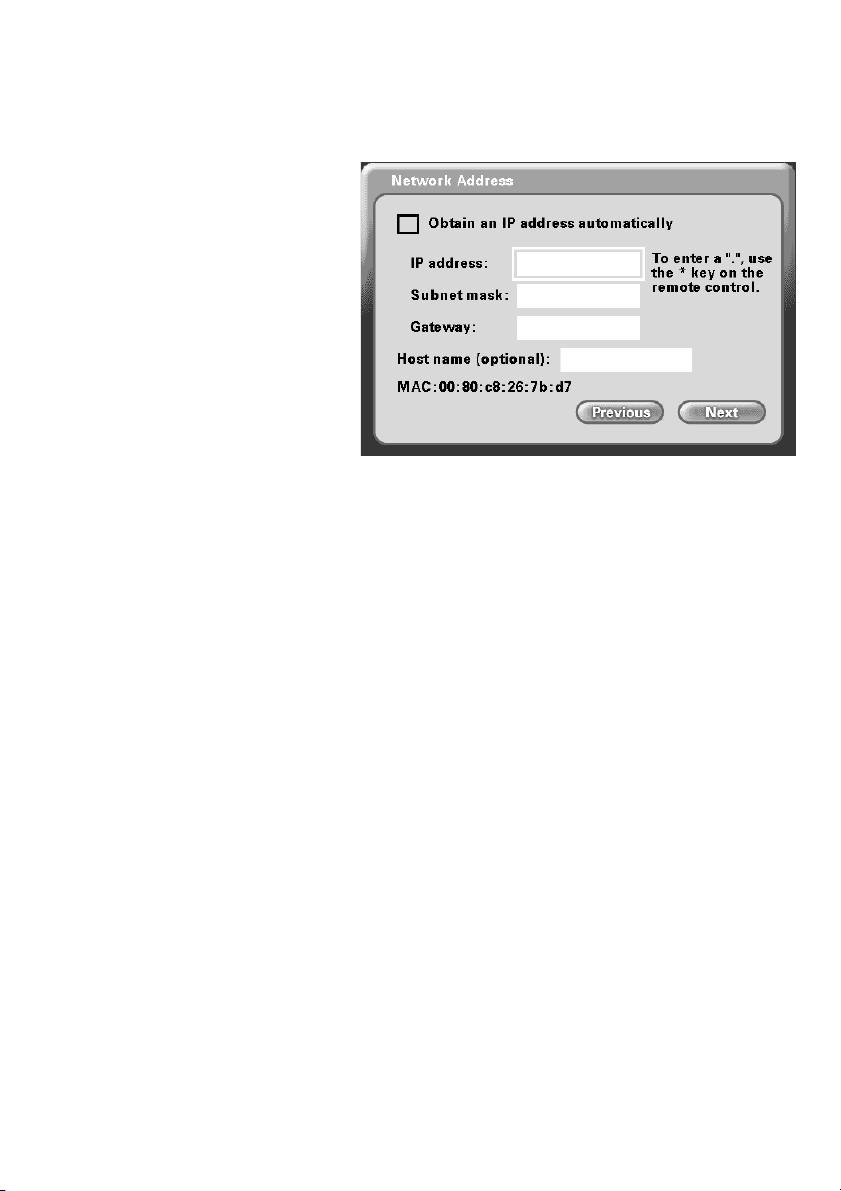
Network Address Screen
The Network Address screen
asks for information that is
needed to connect a DVC-1100
call over the Internet. Most home
users with a cable or DSL
modem can leave the checkbox
checked to obtain an IP address
automatically.
If you know you cannot be assigned an IP Address automatically through a DHCP server
then uncheck the checkbox and enter your IP Address, Subnet mask and
Gateway.
Obtain an IP Address automatically (Default)
The application will attempt to obtain the IP address from the DHCP server.
When this is checked, the other settings on this screen are automatically grayed.
Also, if this setting is checked, you will skip the DNS screen, described on the
next page, as the DNS will be set automatically.
IP Address, Subnet mask, Gateway
If necessary, enter each of these settings for the DVC-1100. You will be able to
obtain the IP address, subnet mask and gateway address from your router
configuration settings, ISP or network administrator.
Host name (optional):
Your Internet Service provider may require you to provide a host name to connect
to the Internet. If this is required you can enter it here. Today, this is rarely
required on a broadband connection and this setting is optional.
MAC: xx:xx:xx:xx:xx:xx
MAC (Media Access Control) is a unique identifier for the Ethernet hardware of
your DVC-1100. If you need to know the MAC address of your DVC-1100, it can
be found on this screen.
Press Next to continue.
15
Page 17
Using the Setup Wizard (continued)
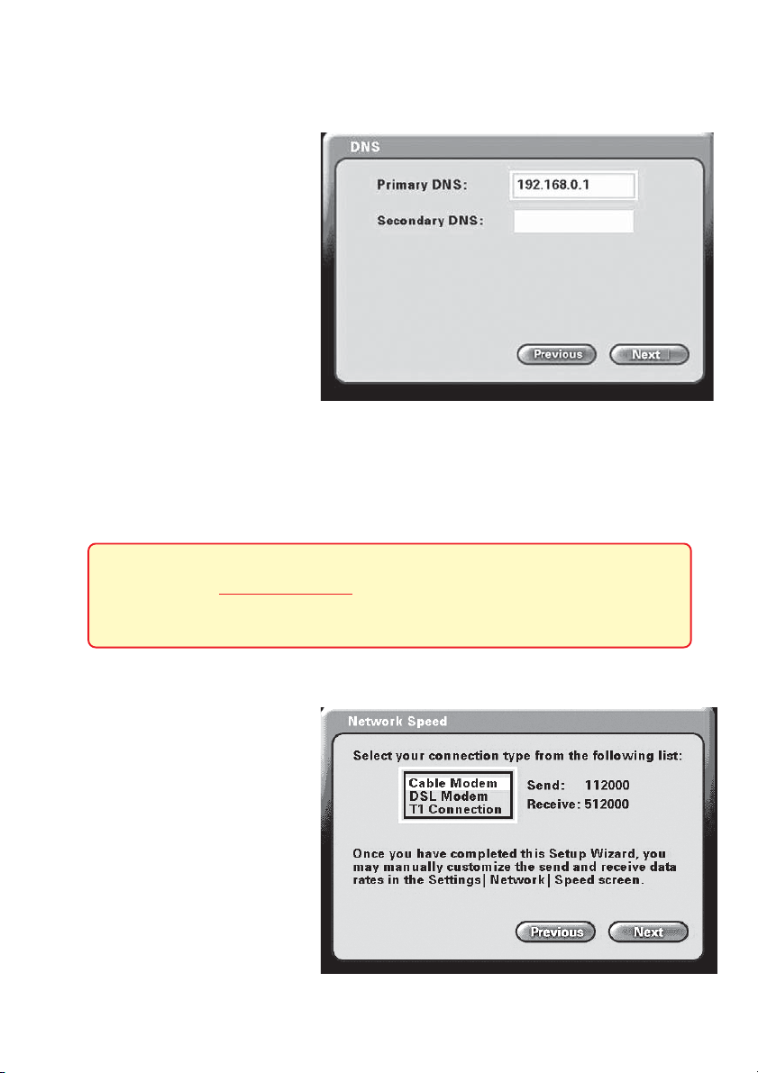
DNS (Domain Naming System) Screen
If you entered an IP address in
the Network Address screen
(described on the previous
page) you will see the screen
for setting DNS server
addresses. The DNS screen
asks for information regarding
the Domain Name System
(DNS) server.
You should be able to get both
of these settings from your
router configuration settings, ISP or your network administrator. Only the primary
DNS server address is required, though it is best to have both the primary and
secondary addresses.
Press Next to continue.
The Domain Name System (DNS) translates Internet domain names
(for example www.dlink.com, which is easy for humans to use and
remember) to IP Addresses, which are what computers use to find
each other on the Internet.
Network Speed Screen
The Network Speed screen
asks you to select the type of
broadband Internet connection
you use. Each choice has default send and receive speeds
defined for you. If you need to
change these settings after
completing the Setup Wizard,
this can be done by selecting
the Settings > Network >
Speed screen.
Press Next to continue.
16
Page 18
Using the Setup Wizard (continued)
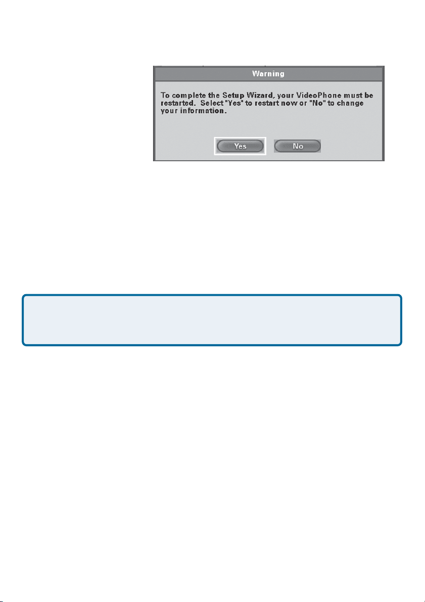
System Restart
A message appears asking
to restart the DVC-1100 to
complete the setup. Press
the Yes button to accomplish a restart.
Congratulations! You are now ready to make and
receive i2eye VideoPhone calls.
Using a Telephone with the DVC-1100
Although optional, it is recommended that you connect a standard telephone to
the DVC-1100 VideoPhone.
The telephone that you use for the DVC-1100 VideoPhone will not
be connected to your phone wall jack. You will use the telephone as
a means of conducting and receiving calls over the Internet only.
The telephone handset is used to place video calls over the Internet, similar to
how you would with a regular phone call. You dial a VideoPhone number to
reach a party on the other end of the VideoPhone call. You can speak through
the telephone, listen to the other party in privacy, and even switch to the
Speakerphone Mode on the DVC-1100 to share the audio with others. This
can all be controlled by the remote control. When the phone is picked up, the
built-in and external microphones are muted. When you receive a VideoPhone
call, the telephone rings.
You can use a cordless phone, a telephone with a speakerphone to replace the
built-in microphone to share the call with others and even use a phone recorder
to allow recording of an audio message when someone calls your VideoPhone
and you are not available.
The DVC-1100 supports dialing methods throughout the world. Please refer to
page 24 for details on how to dial local video calls, calls outside of your Area
code and calls outside of your Country code.
17
Page 19
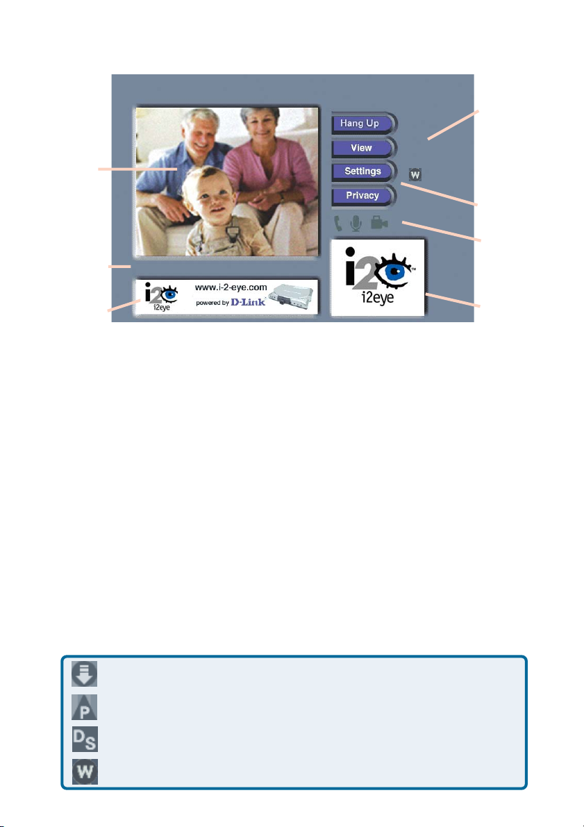
Using the DVC-1100
Status
Icons
Main
Window
Status
Message
Area
Banner
Window
After the DVC-1100 VideoPhone is setup by using the Setup Wizard, you will
see the above Main Screen each time you turn on the VideoPhone.
There is a larger Main Window that displays the self-view until a call is connected.
Once you have connected to another VideoPhone the main window displays the
party you are calling. The smaller Self-View Window then displays the selfview.
To switch the images that are in the Main Window and Self-View Window,
press the Self/Remote button on the remote control.
Ready for call
Layout of the i2eye Main Screen
Main
Settings
Buttons
Privacy
Status
Icons
Self-View
Window
Status Icons
The Status Icons appear only briefly at startup. The DVC-1100 uses these icons
to indicate its status. The icons display on the top right side of the Main Screen.
This is a list of the status icons:
Looking for i2eye updates
Obtaining the Public IP Address (Router’s Address)
DVC-1100 is registering with the Directory Service
Connecting to a Wireless network
18
Page 20

Using the DVC-1100 (continued)
If a Status Icon is displayed, this indicates the operation the icon represents is
not complete. The i2eye Update status icon appears at startup. While the
icon appears, the DVC-1100 is quickly determining if auto-update is enabled. If it
is enabled, the DVC-1100 will determine if an update exists. When this is complete,
the icon disappears.
If the DVC-1100 cannot connect to the update server, the operation was
unsuccessful and the icon will show as: Typically, this means the DVC-1100
is not connected to the Internet.
The Public IP Status Icon, appears at startup when the DVC-1100 attempts
to connect to the Internet and determine the Public IP address of your Internet
connection. If this operation is unsuccessful and the icon shows as: the
DVC-1100 cannot be used over the Internet. It can be used on an internal network
as an internal videoconferencing system.
The Directory Service Status Icon is displayed at startup, showing the
DVC-1100 is registering with the i2eye Directory Service to allow phone number
dialing. If the Directory Service cannot be reached, the icon appears. This
means you cannot use telephone numbers call other VideoPhones, but you can
still make VideoPhone calls by inputting the IP address of the phone that you are
calling. (See Entering IP Addresses on page 26.)
The Wireless Status Icon appears at startup while the i2eye attempts to
connect to the selected wireless network. If the DVC-1100 cannot connect to
the selected wireless network, the icon appears, indicating a wireless
configuration problem exists.
For help, see the Troubleshooting section starting on page 53 if any of the
Status Icons show an unsuccessful operation has occurred.
19
Page 21

Using the DVC-1100 (continued)
Privacy Status Icons
Privacy Status Icons appear on the Main Screen.
Please see page 18 for an illustration.
If you select Audio Privacy in the Privacy Settings
Audio
window, the other party will not hear you and the audio
icon will appear with a slash through it.
Video
Do Not
Disturb
If you select Video Privacy in the Privacy Settings
window, the other party will not see you and the video
icon will appear with a slash through it.
If you select Do Not Disturb in the Privacy Settings
window, your VideoPhone will not ring if dialed and the
other party will receive a message that you are not
taking calls.
Answering an Incoming VideoPhone call
Just like a regular phone call, picking up the telephone handset will answer the
DVC-1100 VideoPhone. You may also use the remote control to answer by pressing the ENTER key when the “Answer” button on the screen is highlighted in a
dialog box.
If the telephone attached to your DVC-1100 is a cordless
model, press TALK on your phone to accept the call.
Placing a Manually Dialed VideoPhone Call with a Telephone
Handset
Pick up the telephone handset.
The DVC-1100 VideoPhone senses the phone is off the hook and a
prompt appears on the screen asking you to either enter a phone
number or press # key to select the Speed Dial List.
Enter the phone number into the DVC-1100 similar to the way you
would if you were using a regular phone. See Entering Phone
Numbers on page 24 for help on completing a videocall.
The DVC-1100 rings while you wait for your call to be answered by
the party on the other end of the call.
When the other party answers, the VideoPhone call is connected.
20
Page 22

Using the DVC-1100 (continued)
Placing a Speed-dial VideoPhone Call with the Telephone
Handset
To add a VideoPhone number or IP address as a Speed Dial entry, please see
page 29.
Pick up the telephone handset.
The DVC-1100 VideoPhone senses the telephone is off the hook and a
prompt appears on the screen asking you to either enter a phone number
or press # key to select the Speed Dial List.
The Speed Dial List appears, displaying the speed dial number assigned
to the party you want to call. Press the speed dial number on the handset.
The DVC-1100 VideoPhone rings while you wait for your call to be
answered by the party on the other end of the call.
When the other party answers, the VideoPhone call is connected.
If the other party has activated their video privacy, you will not see them;
but you will be able to hear them. If they have activated audio privacy,
you can see them; but not hear them. If you have activated your video
privacy, the other party will not see you and if you activated audio privacy,
the other party will not hear you.
Placing a Manually Dialed VideoPhone Call Using the Remote
From the DVC-1100 VideoPhone Main Menu, select DIAL. The
Manual Dial screen appears.
Navigate with the arrow keys on the remote control to the Manual
Dial button and press ENTER.
You can enter a phone number if you and the party you are calling
are connected to the i2eye Directory Service, or you can enter an
IP address (See page 26 for an example of an IP address). If you
are not connected to the i2eye Directory Service, the phone number
box will be grayed out on your screen.
Enter the phone number or IP address and select Dial.
You will hear ringing while you wait for your call to be accepted.
21
Page 23
Using the DVC-1100 (continued)
Placing a Speed-dial VideoPhone Call with the Remote
To add a VideoPhone number or IP address as a Speed Dial entry, please see
page 29.
From the Main Menu, select DIAL. In the Dial screen the Speed
Dial List box is highlighted and the first speed dial entry is selected.
Navigate with the arrow keys to select the speed dial number
assigned to the party you want to call and press ENTER.
The DVC-1100 VideoPhone rings while you wait for your call to be
answered by the party on the other end of the call.
When the other party answers, the VideoPhone call is connected.
When you dial another VideoPhone, the other party must
answer within 10 rings (one minute) or the call will be dropped
and you will receive an “Incomplete Call” message.
Speakerphone Mode
The DVC-1100 has a Speakerphone Mode if the call needs to be shared with
more than one person, or when it is desirable to talk without using the telephone
handset. In Speakerphone Mode, the speaker on the television and either the
built-in microphone in the DVC-1100 or an external microphone are used.
When a call is answered using the remote control, or a call is placed using the
remote control, the DVC-1100 VideoPhone is automatically in Speakerphone
Mode.
Switching From a Speakerphone Call to a Private Call
If you are sharing a VideoPhone call with a group using the Speakerphone
Mode and wish to conduct a private conversation, pick up the telephone handset
and turn down the audio on the television. The others in the group will not be
able to hear the conversation.
If Speakerphone Mode is not enabled by pressing the
‘Speakerphone’ button on the remote control, hanging up the
handset will end the video call.
22
Page 24
Using the DVC-1100 (continued)
Switching From a Private Call to a Speakerphone Call
If a VideoPhone call is in progress using a telephone handset, Speakerphone
Mode can be enabled:
Press the Speakerphone button on the DVC-1100 remote control.
When the dialog appears on the video display telling you to hang up
the phone, go ahead and hang up the phone.
Speakerphone Mode is now active.
When in Speakerphone Mode with the built-in microphone, you should face the
DVC-1100 VideoPhone unit when you speak so the microphone will pick up all
your words. Speak louder as you move further from the microphone. The
recommended distance from the microphone in Speakerphone Mode is 6 to 8
feet. The volume of the built-in microphone can be adjusted from the
Settings>Mic Vol Screen (see page 45.)
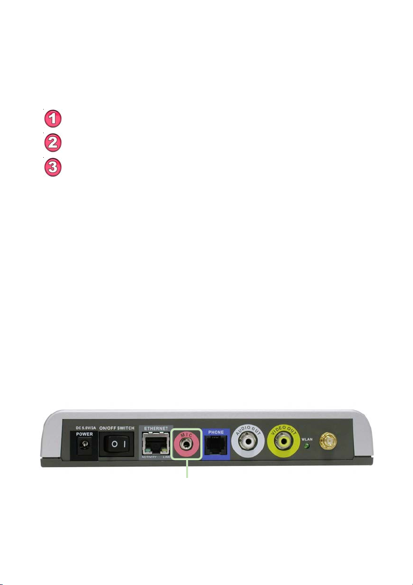
Using an External Microphone for Speakerphone Calls
To enhance the audio in a group videoconference, an external microphone can
be plugged into the external microphone connector on the back of the
DVC-1100. When an external microphone is used, the built-in microphone on
the front of the DVC-1100 is disabled.
External
Microphone
Connector
23
Page 25

Using the DVC-1100 (continued)
Entering Phone Numbers
The DVC-1100 can connect with other DVC-1100 VideoPhones throughout the
world. During the setup of the DVC-1100, you entered a Country code into the
Personal Information screen, along with an Area code and a Phone number.
To make calling a VideoPhone similar to using a regular telephone, you enter
VideoPhone numbers in a format similar to your local telephone system.
Videocalls can be made using the remote control from the Manual Dial screen or
from an attached telephone. When using a telephone, the Country code and
Area code must be dialed along with the Phone number on all calls.
After entering the number into the Phone number box when using the remote
control to make a call, click on the Dial button to begin the VideoPhone call.
Calling a VideoPhone with the Same Country & Area Codes
In the Manual Dial screen, the Country code and Area code you entered for
your VideoPhone are set as the default entries. To complete a call to another
VideoPhone with the same Country and Area codes (i.e., a local video call),
simply enter the Phone number of the party you are calling.
Example: The VideoPhone you are calling has the local VideoPhone number
of 555-1212, you would leave the default Country and Area code boxes and
enter phone number 5551212. To make this call with a telephone handset, you
would dial 12125551212 (Country code+Area code+phone number.)
1
212
5551212
24
Page 26

Using the DVC-1100 (continued)
Calling a VideoPhone with a Different Area Code
To complete a call to another VideoPhone with the same Country code, but a
different Area code (i.e., “a long-distance” call), enter the Area code and Phone
number of the party you are calling. (Remember: The DVC-1100 uses the Internet
for completing calls and not long-distance phone lines!)
Example: The VideoPhone you are calling has an Area code of 949 and a
phone number of 555-1212, you would leave the default Country code box,
enter 949 into the Area code box and then enter Phone number 5551212. From
a telephone handset you would dial 19495551212 to complete this call.
1
949
5551212
Calling a VideoPhone with a Different Country Code
To complete a call to another VideoPhone with a different Country code (i.e., an
“international call”), you need to enter the Country code, Area code and Phone
number of the other party.
Example: The VideoPhone you are calling has a Country code of 886, an Area
code of 2 and a phone number of 5555-1212, you would enter 886 into the
Country code box, 2 into the Area code box and then enter Phone number
55551212. From a telephone handset, you dial 886255551212 to complete
this call.
886
2
55551212
25
Page 27

Using the DVC-1100 (continued)
Entering IP Addresses
Calling a VideoPhone or H.323 Device with an IP Address
If you are unable to Dial another DVC-1100 by using its Phone number, you can
complete a call by entering the IP Address of the VideoPhone you want to call.
This will require obtaining the IP Address for the device you want to call.
To complete a call to another VideoPhone or any other compatible H.323compliant videoconferencing device, ignore the Country code, Area code and
Phone number boxes in the Manual Dial screen. Use the remote control to
move the cursor to the Enter an IP Address box.
Example: The VideoPhone or other device you are calling has an IP Address of
205.104.32.20, you would use the remote control to enter:
205 and then press the * key to enter a period
104 and then press the * key to enter a period
32 and then press the * key to enter a period
20 and then press the * key to enter a period.
Then click the Dial button to complete this call.
205.104.32.20
The DVC-1100 supports domain name lookup. This means you can use the
domain name of a website as the IP address, if a VideoPhone is connected
to this website. For example, you can avoid entering an IP address number
and instead use the on-screen keyboard to dial an address such as:
www.myvideophone.com
26
Page 28

Using the Configuration Menu
Main Screen
Ready for call
After starting the DVC-1100 VideoPhone, the Main Screen is displayed. The
self-view image should be displaying in the larger window. The following buttons
reside on the main screen:
Dial
Set up a speed dial list and choose from several methods of
placing a call to other VideoPhones. You can make a call by
entering an i2eye VideoPhone number, by entering an IP
address, or select an entry on the speed dial list.
View
Settings
Privacy
If this warning screen appears, click OK
and you will be shown the IP address
configuration screen. Manually input the
IP Address. Please see #19 in the
Troubleshooting Section in this manual
for more information.
Allows you to specify what is seen on the main application screen.
Choose full screen view or the default view, as well as Internet
connection status.
Change settings relating to video calls, personal information
and network information.
Select from several methods of audio and video privacy.
27
Page 29

Using the Configuration Menu (continued)
Main Screen > Dial
D-Link
Grandma
Mary
Mom and Dad
School
Ted’s Farm Supply
Work
The Dial screen contains the Speed Dial List as well as buttons to manage
the Speed Dial List and make manual VideoPhone calls
Speed Dial List
Manual Dial
This list contains up to 50 Speed Dial entries. Click the
Add button to add to this list. A name is dialed by highlighting
the item and pressing the ENTER button on the remote.
After 10 entries are created, the Speed Dial List will scroll
to display entries 11 through 50.
Allows the manual dialing of another user by telephone
number or IP Address. When you click Manual Dial in the
screen above, the window below will appear. To enter the
phone number or IP Address, use the remote’s number pad
or the on-screen keyboard.
Click Dial to start the VideoPhone call.
28
Page 30

Using the Configuration Menu (continued)
Main Screen > Dial (continued)
Add
Remove
Edit
To add a Speed Dial entry, enter a name and a number
(or an IP address) using the remote’s number pad or the
on-screen keyboard.
John Smith
1
949
555-1212
Click OK to complete the addition of a Speed Dial entry.
Removes a selected entry from the Speed Dial List.
Allows the modification of either the name or number (or
IP address) of a selected Speed Dial entry.
Close
If this Warning screen
appears, an invalid IP
address has been
entered. Please correct
the IP Address and try
again.
Closes the Dial screen, saving the current entries in the
Speed Dial List.
29
Page 31

Using the Configuration Menu (continued)
Main Screen > View
The View screen allows the user to modify what the Main Screen may look like.
Default View
Full Screen View
Display Connection
Status
Details (Button)
View Connection Details
This is the standard view showing both the larger
main view window and the smaller self-view
window.
The main video window is seen in this view. When
no call is in progress, the self-view will display.
Once a call is connected, the remote caller’s video
will display as well as a self-view picture-in-picture.
This view is the same as the default view with the
addition of connection status information
appearing in the lower left corner of the main
screen.
Click this button to view the connection details.
Items such as video and audio formats and call
rates will be displayed. The connection details can
be viewed only while the DVC-1100 VideoPhone
is on a call.
30
Page 32

Using the Configuration Menu (continued)
Main Screen > Settings
The Settings screen contains six buttons that allow the DVC-1100 to be
customized in different ways. Each of these settings are detailed starting on the
next page.
General
Controls settings that adjust the way you view, listen and
use the DVC-1100 VideoPhone.
Personal
Information
Network
Update
Video
Mic Vol
Close
Contains information about the user and allows editing of
user information.
The Network Settings screen has six buttons that allow you
to setup your network address, DNS address, public IP Address, transmit and receive network speeds, a PING network diagnostic tool and wireless settings.
DVC-1100 will look for system updates each time it starts
up. This setting allows you to search for an update manually.
Adjustments to the video display settings can be made.
Used for adjusting the volume of the built-in microphone
on your DVC-1100.
Closes the Settings Screen and returns you to the Main
screen.
31
Page 33

Using the Configuration Menu (continued)
Main Screen > Settings >General
Always answer
incoming calls
Turn on video privacy
when answering calls
Play sound with
user input
Automatically adjust
video contrast
Selecting this checkbox allows the DVC-1100 to
automatically accept any incoming call. You will hear
two short beeps if a call is received with auto-answer
enabled. If this checkbox is not selected and a call is
received, a dialog box appears asking if you want to
accept the incoming call.
When this checkbox is selected, Video Privacy will be
turned on whenever a call is received. This blocks a
caller from seeing the you until you turn off video
privacy.
Select this checkbox to hear a beep with each function
pressed on the remote control. You will hear no sound
when using the remote control if this is not selected.
Selecting this checkbox causes an automatic
adjustment of the video contrast every 30 seconds.
When this is selected the Video button on the
Settings screen is unavailable and the video settings
cannot be adjusted (see page 44). The Contrast
button on the remote control triggers a manual
adjustment of the video contrast regardless of the
selection state of the checkbox.
32
Page 34

Using the Configuration Menu (continued)
Main Screen >Settings > Personal Information
John Smith
1
555-1212
949
555-1212
Name
Country
Code
Area Code
& Phone #
Enter your name here. When a call is placed from your
VideoPhone, the name you enter will be displayed as a Caller
ID on the remote end of the call. Unless the VideoPhone you
call has auto-answer turned on, the party you wish to call will
decide whether or not to accept your call based on this name.
Each country is assigned a Country code for making video calls
between countries, similar to the regular international telephone
system. The Country code for the United States and Canada is
“1”. Other Country codes are listed on page 71. Enter your
Country code here (up to 3 digits).
The Phone number is one you create for friends, family, and
others to call you. This is not associated with your home phone,
though you may wish to use your home phone number to make
remembering the number easier. Or you may make up a new
one. This phone number will not be visible to any other users.
The DVC-1100 can support global phone number formats.
(up to 4 digit area codes and up to 9 digit phone numbers are
supported).
33
Page 35

Using the Configuration Menu (continued)
Main Screen > Settings > Network
Address
DNS
Public IP
Speed
PING
Wireless
Controls how the DVC-1100 obtains an IP address.
Allows you to enter a primary and secondary DNS
address.
This screen controls how a public IP address is
obtained. If the Public IP button is “grayed out”, it
means that your DVC-1100 is in the process of searching for a public IP address. If this lasts for more than
30 seconds, the DVC-1100 will most likely not find a
public IP address. Please see #16 in the Trouble-
shooting section in this manual for more information.
Allows for setting transmit and receive speeds that
best match your current connection.
The PING network utility allows you to test the
network connection of the DVC-1100 by “pinging” an
IP address.
Allows Wireless mode to be enabled and the wireless
settings to be accessed.
34
Page 36

Using the Configuration Menu (continued)
Main Screen > Settings > Network > Address
X
Obtain an IP Address
automatically
IP Address,
Subnet mask &
Gateway
Host name (optional)
MAC:xx:xx:xx:xx:xx:xx
When this screen
appears, Click OK to
save the changes and
restart the system.
The DVC-1100 VideoPhone will attempt to obtain the
IP Address from the DHCP server. When this is
checked (the default), the other settings on this screen
are automatically grayed.
These are all Internet settings that need to be provided
by your router configuration settings, ISP or network
administrator. These will be grayed if the checkbox
(above) is checked.
Used for reporting the host name to the router/home
gateway in the DHCP table. This is rarely used and is
optional.
MAC (Media Access Control) is a unique identifier for
the Ethernet hardware of your DVC-1100. If you need
to know the MAC address of your DVC-1100, it can be
found on this screen.
35
Page 37

Using the Configuration Menu (continued)
Main Screen > Settings > Network > DNS
Primary DNS
Secondary DNS
The Domain Name System (DNS) translates Internet domain names
(for example www.dlink.com which is easy for people to use and
remember) to IP addresses, which are what computers use to find
each other on the Internet.
Enter the Primary Internet DNS (Domain Name System).
These are Internet server addresses that you should be
able to obtain from your router configuration settings, ISP
or network administrator.
Enter the Secondary DNS address if you have one. Though
both primary and secondary DNS addresses are preferred,
only the primary address is required.
36
Page 38

Using the Configuration Menu (continued)
Main Screen > Settings > Network > Public IP Address
This screen allows you to view or edit the VideoPhone’s public IP address.
If you are sharing a broadband connection with another device (such as a PC),
you typically will need a router to accomplish the sharing of the connection.
Your router will usually have a Network Address Translation (NAT) mode installed. The NAT affects the IP address of the DVC-1100 and any other devices
sharing your Internet Connection. See the Glossary on page 67 for a description
of a NAT.
Auto-detect public
IP address
Use Private IP
address
Specify public IP
Public IP address
This is the default and recommended setting. If the
DVC-1100 is behind a NAT router, and you leave this
checkbox selected, the VideoPhone will automatically use
your public IP address for placing and receiving calls. On
the majority of Cable and DSL broadband systems, leaving
this checked will result in simplified installation and use.
(Optional) Select this checkbox if you want to use your
VideoPhone ONLY within a private network (LAN). If you
select Use Private IP address, the VideoPhone will not
be able to place or receive calls outside the private network
and the Status Icons on the Main Screen will appear with
an “X” to indicate the DVC-1100 is not connected to the
public Internet.
(Optional) Select this checkbox if you want to manually
change the DVC-1100 VideoPhone’s public IP address.
Using the number pad on the remote or the on-screen
keyboard, enter the public IP address. (Only available for
editing when Specify public IP is selected.)
37
Page 39

Using the Configuration Menu (continued)
Main Screen > Settings > Network > Network Speed
The Network Speed screen offers you the option of selecting the speed that
is the best match for your current network or connection.
Change the settings by selecting the send or receive Change button and
select the value desired by moving the selection up or down in the list box.
Overestimating these settings may affect the call quality and is not
recommended. Contact your ISP, network administrator, or look in your
modem manual for correct values. The send and receive settings can
be different speeds. Typically Cable and DSL modems receive at a higher
speed and send at a lower speed.
38
Page 40

Using the Configuration Menu (continued)
Main Screen > Settings > Network > PING
PING is a network or Internet utility, used to test a network or Internet connection. If you are having problems establishing a connection to another
VideoPhone after the setup of the DVC-1100, you can use the PING function to
test if your Internet connection is working correctly.
To use the PING function, from the remote control enter a known IP Address on
your network or on the Internet into the Input Host Address box. Press the
PING button. If the IP address is valid, and the connection is made
successfully, a “Pass. Host is Reachable” message is received. If you enter a
valid IP Address and the PING utility fails to reach the host, you will receive a
“Fail. Host is not Reachable.” message. This indicates that a possible problem
with your Internet connection exists.
Press OK after you are done to return to the Network Settings screen.
39
Page 41

Using the Configuration Menu (continued)
Main Screen > Settings > Network > Wireless Site Survey
47 i2eye AP
42 Router
36 Default
36 Daisy95
33 Study001
18 Sam’s AP
Upon startup, the DVC-1100 performs a “site survey” looking for available wireless networks. Any discovered wireless devices are displayed by their SSID
name. On a home network, you may have just one entry. In a business, there
may be numerous wireless devices listed. The number to the left of a SSID
indicates the signal strength of the available access point on the wireless network.
The DVC-1100 also displays the result of the SSID that is currently selected. A
Connection OK message appears if the connection is successful. If the connec-
tion fails the message Connection Failed appears. See the Troubleshooting
section starting on page 53 for help.
Enable Wireless
The checkbox is checked by default, allowing the
DVC-1100 to be used wirelessly. If an Ethernet network cable is used to connect to a network instead,
uncheck this checkbox and press Close to return to
the Network Settings screen.
Scan
Settings
Press to update the SSID list of wireless devices.
Press the Settings button to access the Wireless Set-
tings screen to edit the SSID name and to set wireless
encryption settings.
Close
Press to return to the Network Settings screen.
Use the remote control up/down arrow buttons to select the SSID of the device
you will connect the DVC-1100 to. Press ENTER on the remote to select this
SSID and the Wireless Settings screen will appear (see next page.)
40
Page 42

Using the Configuration Menu (continued)
Main Screen > Settings > Network > Wireless Site Survey > Wireless
Settings
i2eye AP
The Wireless Settings screen controls the following wireless connection and
encryption settings on the DVC-1100:
SSID
The name of the selected wireless device from the Wireless Site Survey screen. This name can be entered
or edited using the on-screen keyboard (e.g., if the SSID
broadcast feature on a wireless device was disabled
and the SSID did not appear on the Wireless Site Sur-
vey screen). The connection status for the selected
SSID device is displayed next to the SSID (Connection
OK or Connection Failed).
Auth Type
WEP Type
Select one of the following authentication modes:
Open Key: Communicates the key across the network.
Shared Key: Allows communication only with devices
with identical encryption settings.
The WEP Encryption key can be set to 64, 128 or 256
bit-length. The WEP Type must match the WEP en-
cryption bit-length on the wireless network.
41
Page 43

Using the Configuration Menu (continued)
Main Screen > Settings > Network > Wireless Site Survey > Wireless
Settings (continued)
Key ID
Keys
Details on Entering Encryption Keys
Keys are entered in hexadecimal format, meaning you can use the numbers 0
through 9 and the letters A through F. The key must be entered as a specific
number of characters to be accepted as a valid key. See page 13 for additional
details on entering encryption keys.
Only one key needs to be entered. Press the down arrow after entering the first
key to continue to the next box. When you have entered all the keys desired,
press the down arrow and press the Apply button.
Selects which of the four keys, listed to the right on the
screen, is the active encryption key. You can enter up to
four encryption keys that are used to encrypt data
passed wirelessly over the network. Only one of the
keys are used for encryption. You can enter a key for
use, enter up to three other keys for later use and easily
change from one key to another by changing the Key
ID that controls which key is in use.
The four numbered boxes are used to enter from one to
four encryption keys. To connect to an encrypted wireless device, the key you enter in the DVC-1100 must
match the key of the wireless device.
The DVC-1100 will attempt to connect to the selected SSID, using the settings
on the Wireless Settings screen. If the connection fails (probably due to a
wireless network settings incompatibility), the message Connection Failed
appears. You will need to determine what wireless network settings are causing
the failed wireless connection. See the Troubleshooting section on page 58
for help.
If the Connection OK message appears, the DVC-1100 has successfully connected to the selected SSID.
Press the OK button to save any changes and return to the Wireless Site
Survey screen (see page 40).
42
Page 44

Using the Configuration Menu (continued)
Main Screen > Settings > Update
The Update screen has several functions:
Click the box to automatically check for updates of the DVC-1100
VideoPhone. It is recommended this checkbox is checked to allow
updates to be found.
Check for an update right now.
Displays the current version information.
Set Defaults will restore all settings to factory defaults. This will also
erase all speed dial entries that have been added.
If you select Check Now for an Update then the DVC-1100 will check for an
update. If an update is found the following message will appear.
Clicking YES will begin an update of the firmware in the DVC-1100. A restart
of the DVC-1100 is required after the update is complete.
43
Page 45

Using the Configuration Menu (continued)
Main Screen > Settings > Video
You can fine tune the video display from the Video Settings screen. Control
over the following settings is available:
• Color Saturation
• Image Brightness
• Image Contrast
• Video AGC Gain
To adjust any of the four video controls:
1. Use the up/down remote control arrow keys to select which control
needs adjustment.
2. Press the right arrow to increase the setting and the left arrow to
decrease the setting.
Note: You are changing the Video Settings for the local Self-view only. You cannot
change the settings of a remote VideoPhone you are on a call with.
Press OK after you are done to return to the Settings screen.
If the Video button is grayed out on the Settings screen, the Automatically adjust
video contrast has been activated on the Settings>General screen. The
Automatically adjust video contrast checkbox needs to be unchecked to allow
access to the Video Settings. The default setting is unchecked, allowing access to
the Video Settings.
44
Page 46

Using the Configuration Menu (continued)
Main Screen > Settings > Mic Vol
You can adjust the volume of the built-in microphone from the Volume
Adjustment screen. This adjustment will control how the party on the other
end of the VideoPhone connection hears you.
To adjust the volume, press the right arrow on the remote control to increase
the setting and the left arrow to decrease the setting. The slider bar will
indicate the volume level.
Click the Apply button to save the change.
Press OK after you are done to return to the Settings screen.
Note: A high microphone volume may cause audible feedback, resulting in
an echo that can affect how clearly the other party hears you.
45
Page 47

Using the Configuration Menu (continued)
Main Screen > Privacy
Audio Privacy
Video Privacy
Do Not Disturb
Audio Privacy prevents the audio on your side from
being sent to the remote caller. No one on the other
end of the VideoPhone call will be able to hear you if
this setting is checked, although they can see you.
Video Privacy keeps your video from being sent to
the remote caller. The person on the other end of the
videoconference call will not be able to see you if this
setting is checked.
This setting will keep a caller from being able to connect
to your VideoPhone. When a caller tries to connect with
you, they will receive a message indicating that you are
unavailable.
46
Page 48

Using the DVC-1100 with D-Link Routers
Most D-Link routers now support a feature that allows for easy one-click
configuration of the DVC-1100. You will not need to manually configure the
ports. Upgrading your router to the latest firmware might be necessary to
support this feature. If you have other routers or you are having difficulty
with the DVC-1100, please read the information on pages 48 through
page 52 to learn how to open ports on routers.
To complete the configuration that allows the DVC-1100 to work with your
D-Link router, the D-Link DI-614+ router is shown above. In the DI-614+
configuration utility, go to the Advanced>Virtual Server screen and check the
DVC-1000 box from the list on the page. No other configuration is needed, with
supported D-Link routers, to use the DVC-1100.
47
Page 49

Using the DVC-1100 with Routers, Gateways or Broadband Modems
Opening Ports on Your Routers and Gateways
The firewall security features built into most routers and gateways may prevent
users from accessing the video and audio of their DVC-1100.
A router connects to the Internet through a series of numbered ports. The ports
used by the DVC-1100 are often blocked from access over the Internet by the
firewall features of the router.
You may be able to connect to another VideoPhone, but not receive any video
or audio. This is a typical scenario of a firewall blocking the ports needed by the
DVC-1100 to send audio and video.
If this is the case, you need to open the ports on your router to the Internet to
allow access to the DVC-1100.
The port numbers used by the DVC-1100 are:
1720
15328
15329
15330
15331
15332
15333
The router or gateway that you are using may be different from the D-Link
DI-614+ wireless router example shown on the following pages. However, the
general procedure for opening ports will be similar. (If you do not have a D-Link
router, look for Virtual Server, Firewall Rules, Port Forwarding, Advanced or
Firewall in your router’s configuration utility.)
In the example that follows, we begin by opening the DI-614+ Web configuration utility and going to Advanced > Virtual Server.
Follow the steps on the next 2 pages to open the ports on your router for successful operation of the DVC-1100.
48
Page 50

Using the DVC-1100 with Routers, Gateways or Broadband Modems (continued)
Opening Ports on Your Routers and Gateways (continued)
How to open ports on a router
A
B
C
D
15328
E
15328
F
G
A total of 7 ports must be opened for the DVC-1100 to work with most routers
or firewalls. To open these ports, please do the following:
A. Click Enabled
B. Give the Virtual Server a Name (such as i2eye)
C. Under Private IP, enter the IP Address obtained from the
DVC-1100
(How to obtain an IP Address from the DVC-1100:
Turn the DVC-1100 ON. Using the remote control
highlight the Settings button on the Main Screen.
Navigate to Settings>Network>Network Address
>IP Address)
D. Under Protocol Type, choose Both (TCP and UDP)
E. Under Private Port and Public Port, enter 15328
F. Under Schedule, click Always
G. Click Apply to save this entry
49
Page 51

Using the DVC-1100 with Routers, Gateways
or Broadband Modems (continued)
Opening Ports on Your Routers and Gateways (continued)
You have now completed the entering of one port to be opened. You will need to
open six more ports.
Repeat steps A through G five more times for each one of the following five
ports: 15329, 15330, 15331, 15332 and 15333.
The last port will be opened slightly differently:
Repeat steps A through C on the previous page.
Choose TCP as the Protocol Type
Enter 1720 as the Private Port and Public Port
Under Schedule, Click Always
Click Apply to complete
You have now completed the opening of the 7 ports. Your DVC-1100 is ready to
use with your router or gateway!
(Important: Not all routers and gateways are the same; please refer to your
user manual for specific instructions on opening ports.)
50
Page 52

Using the DVC-1100 with Routers, Gateways, or Broadband Modems (continued)
From the following sections, choose the heading that best applies to your
equipment or networking configuration.
Network With Multiple Public IP Addresses
A Public IP Address is visible on the Internet. (Most commonly found in business
environments.)
Recommended Procedure: If there is an available public IP address, simply
enter the IP address, subnet mask, and gateway into the applicable fields in the
Network Settings screen. If the network has a DHCP server, select the checkbox
under the Network Settings that says, “Automatically obtain IP address.” (The
network administrator will be able to tell you whether or not the network has a
DHCP server.)
Potential Issues: Some firewalls are configured in a way that could potentially
restrict H.323 data flow. Most current corporate firewalls are H.323 compliant.
If this is the case, configuring the firewall is accomplished by simply opening
the necessary H.323 ports into the network:
Port 1720 (TCP)
Ports 15328 – 15333 (UDP & TCP)
If your particular firewall does not have this option, consult the firewall’s
documentation on how to open specific ports needed for H.323 communications.
Broadband Modem and One PC
(This is the most common scenario found in a home or home office that currently
has one PC connected to its broadband modem.)
Recommended Procedure: Request from your ISP an additional public IP address.
With a second public IP address, the VideoPhone will be visible to the outside
world just as the existing PC. The ISP can either assign a static IP address or
allow you to dynamically request the IP address via DHCP. Follow the instructions
in Broadband Modem Only section, below, depending on what your ISP requires.
Because most broadband modems have only one Ethernet port, it will be
necessary to install a hub or switch between the modem and the rest of the
network. Using an Ethernet cable, connect the modem’s Ethernet port to the
applicable uplink port on the hub. Once that is done, you can plug the PC and
DVC-1100 VideoPhone into any other available port.
51
Page 53

Using the DVC-1100 with Routers, Gateways, or Broadband Modems (continued)
Broadband Modem, Multiple PCs and a Hub
Commonly found in small offices, home offices, or homes with more than one
PC where multiple public IP addresses are available.
In order to install the DVC-1100 VideoPhone as another device behind a hub
assign an available public IP address to the VideoPhone.
Refer to the Broadband Modem Only section, below, for detailed installation
instructions.
Broadband Modem, Multiple PCs and a Router
Commonly found in small offices, home offices, or homes with more than one
PC where only one public IP address is available.
Refer to the Using the DVC-1100 with Routers, Gateways or Broadband Modems
section starting on page 48 for detailed installation instructions.
Broadband Modem Only
This section applies only in the instance that the broadband connection is used
exclusively with the DVC-1100 VideoPhone and there are no PCs or other devices
connected to the broadband modem. Broadband cable modems allow this type
of installation.
Recommended Procedure: Many ISPs act as DHCP servers and dynamically
assign a public IP address whenever the modem requests one. If your ISP has a
DHCP server, select the checkbox under the network settings that says,
“Automatically obtain IP address.” By choosing this option, you are not required
to know the IP address, gateway, subnet mask, or DNS numbers. They will all
be filled in automatically.
If DHCP is not an option, all of the networking values will have to be manually
entered. Simply enter the public IP address, subnet Mask, gateway, and DNS
numbers given to you by the ISP into the appropriate network settings fields.
Potential Issues: In order for the DVC-1100 VideoPhone to function properly
over the Internet, there must exist a public IP address for the world to see. If
your ISP is acting as a NAT and assigning private IP addresses, you will have to
request a public IP address in order for your VideoPhone to be able to receive
calls.
52
Page 54

Troubleshooting
1. Cannot make a call using a phone number.
Check that you did not misdial the number.
Remember to dial a country code and area code for all calls when using
a telephone handset to make video calls.
The VideoPhone is not connected to the Internet.
The VideoPhone is not registered with the Directory Service. It
may take the VideoPhone up to 10 minutes to register. Verify all network
settings, including DNS.
Far side of the call is not registered with the Directory Service. If
you are calling someone who has an videoconference
endpoint besides a DVC-1100 VideoPhone, you will have to make direct
IP calls to them. If the far side has a DVC-1100 VideoPhone and you
cannot connect to them via the Directory Service, they are probably not
registered.
2. Cannot make direct IP calls.
VideoPhone is not connected to the Internet. See the Internet
Connection section (starting with #19) in this Troubleshooting Guide.
The person you are trying to call is unreachable. Ensure the IP
address of the person you are trying to call is correct.
3. Telephone or television produces an off-hook signal.
Telephone is off the hook. Hang up the phone.
4. Telephone or television produces a fast busy signal.
Person you are trying to call is not registered with the directory
service. Call the person using direct IP or wait until the person is
registered with the directory service.
Person you are trying to call is in a call or has rejected your call.
Try your call at a later time.
53
Page 55

Troubleshooting (continued)
5. Picking up the phone displays a window with speed dial list or
brings up a message about no entries in the speed dial list.
VideoPhone is not registered with the Directory Service.
Sometimes it takes the VideoPhone up to ten minutes to register.
Verify all network settings, including DNS.
6. Telephone doesn’t ring with an incoming call.
VideoPhone is set for Auto-Answer. If the VideoPhone is set up for
Auto-Answer then the phone will not ring with an incoming call. Fix by
turning off Auto-Answer via the Settings>General menu.
Telephone is not properly plugged in. Ensure that the phone is
properly plugged into the VideoPhone. If the telephone is not selfpowered, ensure that it is properly plugged into a power supply. Consult
your telephone user manual for reference.
Telephone ringer is off. Make sure the ringer on the phone is turned
on. Consult your telephone user manual for reference.
7. VideoPhone freezes-up while answering a call.
VideoPhone is not functioning properly behind a firewall.
See next section, “No video in a call” solution.
8. Poor video in a call.
Camera out of focus. The far site should focus their camera by twisting
the knob on the VideoPhone until the image is in focus.
Incorrect Network Speeds. See # 23 Incorrect Network Speeds in
this Troubleshooting Guide.
Excessive motion in the picture you are receiving. A background
with less motion provides a better, smoother video picture.
54
Page 56

Troubleshooting (continued)
9. No video in a call.
Video cables are not plugged in correctly. Ensure that your video
cables are correctly plugged into the TV. Make sure that the TV is set for
video input. Consult your TV manual for reference.
Incorrect network speeds. See #23 Incorrect Network Speeds Section
in this Troubleshooting Guide.
VideoPhone is not functioning properly behind a firewall.
Place the IP address of the VideoPhone in the DMZ of the firewall. Consult
your router’s documentation or your network administrator for help on
doing this.
Port forward the appropriate ports to the VideoPhone. The
VideoPhone needs ports 1720 (TCP) and ports 15328-15333 (TCP and
UDP) open to function properly. See the section Using the DVC-1100
with Routers, Gateways or Broadband Modems on page 48, or consult
your router’s documentation or your network administrator for help on
doing this.
VideoPhone is not functioning properly behind NAT.
Go to Settings>Network>Public IP. Press Enter on the remote when
the cursor is over “Auto detect public IP Address.” If the VideoPhone is
unable to detect the public IP Address, it should be entered manually
using “Use specific IP Address.” The VideoPhone’s public IP Address is
given to you by either your ISP or network administrator.
10. Video freezes during a call.
Far side muted their video. If the far side mutes their video you will
not be able to see him or her.
Network is congested. Give the VideoPhone a couple of minutes to try
to recover, or disconnect the call and try again at a later time.
55
Page 57

Troubleshooting (continued)
11. No audio in call.
Audio cables are not plugged in correctly. Ensure that your audio
cables are correctly plugged into the TV. Make sure that the TV is set for
video input. Check the volume level on the TV. Consult your TV manual
for reference.
Telephone is not setup properly. Plug the telephone into the back of
the VideoPhone. If the telephone is powered (cordless) make sure that it
is plugged into a power supply. Consult your telephone user manual for
reference.
Port forward the appropriate ports to the VideoPhone. The
VideoPhone needs ports 1720 (TCP) and ports 15328-15333 (TCP and
UDP) open to function properly. See the section Using the DVC-1100
with Routers, Gateways or Broadband Modems on page 48, or consult
your router’s documentation or your network administrator for help on
doing this.
VideoPhone is not functioning properly behind NAT. Go to the
Settings>Network>Public IP screen. Select “Auto detect public IP
Address.” If the VideoPhone is unable to detect the public IP Address, it
should be entered manually using “Use specific IP Address.” The public
IP Address is given to you by either your ISP or your network administrator.
Incorrect network speeds. See the #23 Incorrect Network Speeds
section in this Troubleshooting Guide
Volume is adjusted incorrectly. You can adjust the volume on the TV
as you would when watching a television show. You might also be able
to adjust the volume on your telephone. Consult your TV and/or telephone
user guide for support.
12.
Audio stops during a call.
Far side muted their audio. If the far side mutes their audio you will not
be able to hear him or her.
Network is congested. Give the VideoPhone a couple of minutes to try
to recover, or disconnect the call and try again at a later time.
56
Page 58

Troubleshooting (continued)
13. Audio has an echo.
Far side television is too loud. The far side television volume needs
to be turned down.
14. Excessive delay during a conversation.
Incorrect network speed settings (too fast). Decrease the send/
receive speeds from the Settings>Network>Speed screen and attempt
the call again.
15. Error
Unable to find the Update Server.
No connection to the Internet.
Local setting may be incorrect.
Firewall not allowing FTP out.
In the above cases, consult your router manual/network administrator.
Update Server is temporarily unavailable.
If the Update Status Icon is the only one showing as “failed”, you will
not be prevented from making and receiving videocalls.
16. Error
VideoPhone cannot obtain public IP Address (Router’s address).
See “VideoPhone cannot obtain IP Address automatically” section, #19
below.
17. Error displays on main screen.
VideoPhone could not register with the Directory Service.
Sometimes it takes the VideoPhone up to ten minutes to register. Verify
all network settings, including DNS. Check your network settings. If this
is the only Status Icon showing as “failed”, you will not be able dial a
VideoPhone number to make a call. It will be necessary to dial using an
IP address.
displays on Main Screen.
displays on main screen.
57
Page 59

Troubleshooting (continued)
18. Error message displays on main screen.
VideoPhone could connect to the selected wireless network.
Check the status of other wireless devices on the network. Confirm the
wireless router and any access points are configured and operating
normally.
Wireless settings do not match wireless network settings.
Check the wireless settings for the network wireless router or access
point. Confirm the SSID, authentication type, key length match. Make
sure encryption is enabled or disabled on all wireless devices.
Move the VideoPhone closer to the selected wireless device. The
wireless range to the router or access point may be a problem. Also,
see #25 Wireless Network Hints and Tips below.
19. VideoPhone cannot obtain IP Address automatically
Not properly connected to a DHCP server. Check connection to LAN,
by verifying a link light on the back of the VideoPhone. Make sure that
the router is setup for DHCP. Consult either your router’s user manual
for reference or your network administrator.
IP Address is not accessible to the VideoPhone.
Need to statically assign an IP Address, subnet mask, gateway and DNS
values. If the VideoPhone is on a private network consult your router’s
user manual or network administrator.
Broadband Modem not enabled to assign more than one private
IP (This is common in DSL environments)
Reset modem. Once booted, connect the VideoPhone and allow the
DHCP function to assign an IP (be sure both the Obtain an IP address
automatically checkbox on the Network Address screen and the Auto-
detect Public IP checkbox on the Public IP Address screen are checked.
20. Public IP button is not enabled.
VideoPhone hasn’t been able to detect IP Address yet.
The VideoPhone can take up to ten minutes to auto detect the public IP
Address. Be sure you wait long enough. Also check the DNS settings in
the Network>DNS screen.
58
Page 60

Troubleshooting (continued)
21. VideoPhone reports packet loss.
Incorrect Network Speeds. See Incorrect Network Speeds section in
this Troubleshooting Guide.
Network line is congested. If the packet loss is from one to six percent
it will probably be due to network congestion. The VideoPhone will be
able to recover.
22. VideoPhone is not connected to the Internet.
Ethernet cable is not properly plugged into the VideoPhone. Ensure
that the RJ-45 cable is properly plugged into the back of the VideoPhone.
A steady green light on the Ethernet port indicates a valid link has been
made.
Invalid DNS entries. The VideoPhone requires at least one valid DNS
entry. Consult your ISP or network administrator for the DNS IP Addresses.
Invalid IP, subnet mask and/or gateway. All three of these values
have to be correct for the VideoPhone to function properly. Recheck all
of these values. Consult your ISP or network administrator for these
values.
23. Incorrect network speeds.
Incorrect entries for network speed. Consult your ISP or network
administrator to verify the correct send and receive speeds for your
VideoPhone.
Incorrect entries for network speed. While in a call, turn on
Connection Status from the View menu. If the VideoPhone is reporting
packet loss, decrease your receive speed until the VideoPhone reports
zero percent packet loss. If you are not reading any packet loss, increase
your download speed, to the point where you do not report packet loss.
The far side might need to increase their upload speed to be greater
than or equal to your download speed.
59
Page 61

Troubleshooting (continued)
24. VideoPhone does not boot up.
Video is not being displayed on television.
Ensure that the video and audio cables are plugged in correctly to both
the VideoPhone and television. The television should be set for video
input. Consult your television user manual for support.
The VideoPhone doesn’t have power or is not turned on.
Ensure that the AC adapter is plugged into an outlet and the other end is
plugged into the VideoPhone. The switch on the back of the VideoPhone
must be set to 1 to power on.
Not enough time given to finish booting.
The boot up process could take several minutes. Be sure you wait long
enough. If the VideoPhone still doesn’t boot up, turn it off for one to two
minutes and then turn it back on.
25. Wireless Network Hints and Tips
A wireless network lets you place your DVC-1100 nearly anywhere you
want. However, keep in mind, that range is limited by the number of walls,
ceilings, or other objects that the wireless signals must pass through.
Typical ranges vary depending on the types of materials and background
RF noise in your home or business. The key to maximizing range is to
follow these basic principles:
1. Keep the number of walls and ceilings to a minimum - Each wall or
ceiling can rob your D-Link Air Wireless product of 3-90 ft. of range.
Position your Access Points, Residential Gateways, and computers so
that the number of walls or ceilings is minimized.
2. Be aware of the direct line between Access Points, Residential
Gateways, and Computers - A wall that is 1.5 feet thick, at a 45 degree
angle, appears to be almost 3 feet thick. At a 2-degree angle it looks over
42 feet thick! Try to make sure that the Access Point and Adapters are
positioned so that the signal will travel straight through a wall or ceiling
for better reception.
3. Building Materials make a difference - A solid metal door or aluminum
studs may have a negative effect on range. Try to position Access Points,
Residential Gateways, and Computers so that the signal passes through
drywall or open doorways and not other materials.
60
Page 62

Troubleshooting (continued)
4. Make sure that the antenna is positioned for best reception by using
the software signal strength tools included with your product.
5. Keep your product away (at least 3-6 feet) from electrical devices that
generate RF noise, like microwaves, Monitors, electric motors, etc.
6. If you are using 2.4GHz cordless phones or X-10 (wireless products
such as ceiling fans, lights, and home security systems), your wireless
connection will degrade dramatically or drop completely.
7. For the average home, range should not be a problem. If you
experience low or no signal strength in areas of your home that you wish
to access, consider positioning the Access Point in a location directly
between the Residential Gateways.
8. If you would like to extend your wireless range, you may purchase a
DWL-800AP+, DWL-900AP+ or DWL-1000AP+ to extend the wireless
network. For questions on wireless repeaters please contact sales at
1800-326-1688 There are wireless booster antennas available online,
unfortunately D-Link is unable to support/warranty that.
For more troubleshooting information on D-Link wireless devices,
please visit http://support.dlink.com and search the FAQ section.
61
Page 63

Frequently Asked Questions
1
What is D-Link´s i2eye?
i2eye (TM) is a breakthrough communications video appliance that provides
IP videoconferencing and connects to any standard television. Simple to
install and use, the small unit sits on top of the television and contains a
video camera that can stream up to 30 frames per second over the Internet
to friends, family and business associates.
When connecting my DVC-1100 behind a router or firewall, what
2
ports do I need to open?
The VideoPhone needs ports 1720 (TCP) and ports 15328-15333 (TCP
and UDP) open to function properly.
1100 with Routers, Gateways or Broadband Modems on page 48, or
consult your router’s documentation or your network administrator for
help on doing this. See page 47 when connecting to a D-Link router.
3
I’ve seen videophones that connect using the phone line, and the
picture is always small and choppy. How is i2eye different?
i2eye connects over high-speed broadband, and it delivers up to 30 frames
per second. Videophones using a slow analog plain old telephone line can’t
deliver smooth video pictures over their small LCD display. They show what
appears to be a series of still pictures rather than full motion video
See the section Using the DVC-
4
What is the D-Link Directory Service?
The D-Link Directory Service is a D-Link hosted server which allows you to
register a “phone number” with your DVC-1100 VideoPhone. When someone with a DVC-1100 dials this “phone number”, your DVC-1100 will ring
and you will be able to accept a call. In the same manner you can call
others by dialing their “phone number”. This allows you to contact another
DVC-1100 without knowing its IP address. Any DVC-1100 connected to a
broadband modem will have the capability of using the
Directory Service.
5
Can I use the DVC-1100 with a computer and monitor instead of a
TV?
Yes. The DVC-1100 can be used with a computer and monitor instead of a
TV. However, you will need a TV Tuner / Video Capture device or a video
card that accepts video input from an RCA jack.
62
Page 64

Frequently Asked Question (continued)
6
How large will the image be?
As large as the TV screen. The DVC-1100 supports three screen formats.
The first is a picture-in-picture mode that has the incoming video covering
about half the television screen and the outbound video in a smaller window. The second is full screen mode. This mode displays the incoming
video across the entire television screen. The third is connection status
mode. This mode displays the picture-in-picture mode and gives you an
idea of the upload and download speed.
7
Can I use the DVC-1100 with a non-D-Link directory service?
No. The DVC-1100 is designed to automatically connect to the D-Link
Directory Service. This is a free service and is available to anyone with a
DVC-1100. The Directory Service allows for calling another DVC-1100
VideoPhone by using a phone number instead of using an IP Address.
8
Do I need a PC to use i2eye?
i2eye is a complete standalone system that handles all the communications,
so you don’t need a PC. Just connect it to the TV and broadband connection
and go. You can also use it with any PC with video input capabilities.
9
How easy is i2eye to setup?
Very easy. When users first turn on i2eye they will be walked through a
Setup Wizard that is designed to get the VideoPhone up and working
quickly. The wizard asks for the information needed to connect to a
broadband Internet connection. Once the information is sent, i2eye will
connect to the D-Link i2eye server. The server will assign an “Internet
telephone number” to the device. It will not be necessary to work with
cumbersome IP addresses when you want to communicate using the
i2eye.
63
Page 65

Frequently Asked Question (continued)
11
What devices can I connect to with the DVC-1100?
With the DVC-1100 you can connect to any hardware or software that is
H.323 compatible. If you are not sure if your hardware or software is H.323
compatible, please contact the manufacturer/developer. If you are using a
PC with a Windows operating system, you can use Microsoft NetMeeting
with any webcam to connect to the DVC-1100. NetMeeting is a common
H.323-compatible videoconferencing software application.
What standards drive i2eye?
12
i2eye is based on the H.323 industry standard video streaming over IP
protocol. This ensures that any H.323 compliant device will
communicate together seamlessly. i2eye is a broadband appliance that
draws from D-Link’s seventeen years of experience as a leading
Ethernet manufacturer. The DVC-1100 wireless broadband VideoPhone
uses the 802.11b standard to connect to a wireless network.
Do I have to take every call?
13
i2eye’s configuration menu provides settings for three types of privacy:
Audio Privacy, Video Privacy, and Do Not Disturb, so you are in control.
When the Audio Privacy is activated, incoming callers will be able to see
video from your end, but not hear you. When the Video Privacy is activated,
incoming callers will be able to hear audio from your end, but not see you.
When Do Not Disturb is activated, incoming callers will receive a message
indicating that you are not available. If you do not answer a call within 10
rings (one minute), the call will terminate and the caller will receive an
“Incomplete Call” message.
64
Page 66

Glossary of Terms
802.11b: A wireless networking standard that supports data encryption and up
to 11Mbps bandwidth.
Authentication: The process of verifying a user on a network is who they say
they are and preventing unauthorized users from network access.
Bandwidth: A measure of the rate at which data can be sent and received
through the network. This value is usually given in bits per second (bps)
or Megabits per second (Mbps).
CIF (Common Intermediate Format): An intermediate video format. When
DVC-1100 video is transmitted over a network, the sizes will be CIF,
QCIF, or SQCIF. The VideoPhone will default to CIF. CIF resolution is
352 x 288.
Data Encryption: Encoding network traffic so users without proper decryption
rights cannot properly decode the data.
DHCP (Dynamic Host Configuration Protocol): A protocol that network devices
use to obtain an IP address, subnet mask, gateway and DNS addresses
automatically. A DHCP server can be a router, ISP server, or PC running
Internet connection sharing. See Static IP address.
Directory Service: A service that allows users to make videoconferencing
calls with telephone numbers. It does this by correlating telephone
numbers to actual public IP addresses.
DNS (Domain Name System): A system used to translate computer names
into IP addresses. For example, a DNS server would translate
www.dlink.com into 64.7.210.132.
DSL (Digital Subscribers Line): A technology that delivers digital information
at a high speed through a user’s telephone line. The most common
DSL is ADSL (Asymmetrical Digital Subscribers Line) where the
download speed is usually much higher than the upload speed.
Ethernet: The port on the back of the DVC-1100 VideoPhone that is used to
send and receive data over a network.
65
Page 67

Glossary of Terms (continued)
Far side: The remote connection of the videoconference. Your connection is
the Local Connection.
Firewall: A security mechanism placed between networks, which restricts certain
types of data to devices behind the firewall.
H.323: Standard defining videoconferencing over the Internet.
Home Gateway: A term commonly interchanged with router. Also called a
residential gateway.
IP Address (Internet Protocol Address): An IP Address is a number that
identifies a computer connected to the Internet. Every computer that is
connected to the Internet must have a unique IP Address. An IP Address
consists of four sections separated by periods. Each section contains
an 8-bit value represented as a number ranging from 0 to 255.
Public IP Address: An IP Address that is not behind a NAT router. This
IP Address is visible from the Internet.
Private IP Address: An IP Address that is behind a NAT, which is not
visible to the Internet. The preferred ranges for private IP Address are
either 192.168.x.x or 10.0.0.x.
Dynamic IP Address: An IP Address for a particular network device
(PC, VideoPhone, router) that is dynamically assigned by a router or
ISP and will not remain the same from session to session. See DHCP.
Static IP Address: An IP Address for a particular network device (PC,
VideoPhone, router) that doesn’t change. See DHCP.
ISP (Internet Service Provider): A commercial organization that provides
subscribers with access to the Internet.
Keys (Encryption): Encryption keys allow you to easily change wireless
encryption settings to maintain a secure network. The encryption key
can be of various lengths (e.g., 64, 128 or 256-bit).
66
Page 68

Glossary of Terms (continued)
LAN (Local Area Network): A network that is designed to span small distances.
These are most commonly used in small buildings, businesses and homes
with multiple PCs. See WAN.
NAT (Network Address Translation): A technology that allows multiple network
devices to share the same IP Address. NAT devices forward all incoming
and outgoing information to the correct network devices. Most NAT
devices have firewall capabilities.
QCIF (Quarter Common Intermediate Format): An intermediate video format.
QCIF resolution is 176x144. The DVC-1100 VideoPhone will send QCIFsized video only if the remote endpoint cannot decode CIF.
QoS (Quality of Service): Allows guaranteed bandwidth and packet delivery
between
Router: A device that attaches two or more network devices and forwards data
accordingly. Most consumer type routers act as DHCP servers, NATs
and simple firewalls.
DMZ (Demilitarized Zone): Devices set up to be in the router’s DMZ will see
all network traffic.
network devices over a network.
Port Forwarding: The router will forward public-side incoming information to a
specified device on the private side. The router will forward only the
data that is received on the specified ports. This is usually set through
the advanced settings in the router’s web interface. Also known as
Virtual Server or Firewall Rules.
Ports: A port is a specified path in which data travels. Each type of data that is
transmitted over the Internet travels down a specified port. A router will
forward information from one port to another, and a firewall will open
only a specified number of ports.
SQCIF (Subquarter Common Intermediate Format): An intermediate video
format. SQCIF resolution is 128x96. The DVC-1100 VideoPhone will send
SQCIF-sized video only if the remote endpoint cannot decode CIF or
QCIF.
67
Page 69

Glossary of Terms (continued)
SLIC (Subscriber-Line Interface Circuit): Provides a phone’s analog dial
tone, busy tone, dual-tone multiple-frequency (DTMF) generation and
decoding, caller ID and ring-signaling functions. The SLIC allows the
DVC-1100 to work with a standard telephone without connecting to the
phone system.
SSID: Service Set Identifier (SSID) is the name designated for a specific
wireless local area network (WLAN). The SSID can be easily changed
to connect to an existing wireless network.
TCP (Transmission Control Protocol): An Internet protocol used by the
DVC-1100 VideoPhone in addition to UDP.
UDP (User Datagram Protocol): The Internet protocol most commonly used
by the DVC-1100 VideoPhone to send and receive audio and video data.
WAN (Wide Area Network): A network that is designed to span large distances.
See LAN.
WEP: (Wired Equivalent Protocol): A wireless security protocol for Wireless
Local Area Networks (WLAN). WEP provides security by encrypting the
data that is sent over the WLAN. The DVC-1100 supports 3 levels
of encryption: 64, 128 and 256-Bit encryption. WEP is disabled by
default. The WEP setting can be changed to fit an existing wireless
network or to customize your wireless network.
WLAN (Wireless Local Area Network): A network without wires, connecting
users and devices over a small distance. (See WAN and LAN.)
68
Page 70

Technical Specifications
Internal Processor
ARM-9 ASIC Communications Processor
Standards Compliant
ITU H.323 (IP communications)
Video: H.263
Audio: G.711, G.723
Data Rates/Frame Rates
96 Kbps—512 Kbps
Up to 30fps
Video
Up to 30fps CIF (352 x 288 pixels), QCIF (176 x 144)
Picture-In-Picture (PIP)
Automatic contrast control
DVC-1100 Robust Video
Audio
Telephone interface- Full Duplex Audio
Echo cancellation
Voice only to and from Voice over IP endpoints
DVC-1100 Robust Audio
Half-duplex speakerphone
Input/Output
Power
Audio Out
Video Out
10BaseT Ethernet (RJ-45)
SLIC for telephone
External Microphone
802.11b antenna
Camera
Manual tilt
Manual focus
69
Page 71

Technical Specifications (continued)
LED Indicators
Power
Status
Video monitor
WLAN activity
Network link and transmit
Dialing Capabilities
Speed dial list allows up to 50 entries
Manual dialing with telephone handset using Directory Service
Manual dialing with direct IP entry
Remote Software Update
Software update, automatic or manual
Network
Standard:IEEE 802.3
IP-based network including Ethernet, Cable, DSL, or T-1
DHCP compliant or fixed IP with subnet mask, DNS and gateway
Wireless
Standard: IEEE 802.11b
Data rate: 1, 2, 5.5 & 11 Mbps
WEP Encryption: 64-bit, 128-bit & 256-bit
Wireless Frequency: 2.4 GHz
Physical
Height x Depth x Width
1.50" (38mm) x 7.48" (190mm) x 8.07" (205mm)
Weight:
17 oz. (.48 kg)
Electrical
Power supply:
Auto-switching 2 Amp; 5.0 Volt output
Patent Pending
70
Page 72

List of Country Codes
Code Country
93 Afghanistan
355 Albania
213 Algeria
684 American Samoa
376 Andorra
244 Angola
809 Anguilla
268 Antigua
54 Argentina
374 Armenia
297 Aruba
247 Ascension Island
61 Australia
43 Austria
994 Azerbaijan
242 Bahamas
973 Bahrain
880 Bangladesh
246 Barbados
375 Belarus
32 Belgium
501 Belize
229 Benin
809 Bermuda
975 Bhutan
591 Bolivia
387 Bosnia and Hercegovina
267 Botswana
55 Brazil
284 British Virgin Islands
673 Brunei
359 Bulgaria
257 Burundi
855 Cambodia
237 Cameroon
1 Canada
238 Cape Verdi
345 Cayman Islands
236 Central African Republic
235 Chad
56 Chile
86 China
57 Colombia
269 Comoros and Mayotte
242 Congo
682 Cook Islands
506 Costa Rica
385 Croatia
53 Cuba
357 Cyprus
420 Czech Republic
45 Denmark
246 Diego Garcia
Code Country
253 Djibouti
767 Dominca
809 Dominican Republic
593 Ecuador
20 Egypt
503 El Salvador
240 Equatorial Guinea
291 Eritrea
372 Estonia
251 Ethiopia
500 Falkland Islands
679 Fiji
358 Finland
33 France
596 French Antilles
594 French Guiana
241 Gabon
220 Gambia
995 Georgia
49 Germany
233 Ghana
350 Gibraltar
30 Greece
299 Greenland
473 Grenada
671 Guam
502 Guatemala
224 Guinea
245 Guinea-Bissau
592 Guyana
509 Haiti
504 Honduras
852 Hong Kong
36 Hungary
354 Iceland
91 India
62 Indonesia
98 Iran
964 Iraq
353 Ireland
972 Israel
39 Italy
225 Ivory Coast
876 Jamaica
81 Japan
962 Jordan
7 Kazakhstan
254 Kenya
965 Kuwait
856 Laos
371 Latvia
961 Lebanon
266 Lesotho
71
Page 73

List of Country Codes (Continued)
Code Country
231 Liberia
218 Libya
423 Liechtenstein
370 Lithuania
352 Luxembourg
853 Macao
389 Macedonia
261 Madagascar
265 Malawi
60 Malaysia
960 Maldives
223 Mali
356 Malta
692 Marshall Islands
222 Mauritania
230 Mauritius
52 Mexico
373 Moldova
33 Monaco
976 Mongolia
473 Montserrat
212 Morocco
258 Mozambique
95 Myanmar (Burma)
264 Namibia
674 Nauru
977 Nepal
31 Netherlands
599 Netherlands Antilles
869 Nevis
687 New Caledonia
64 New Zealand
505 Nicaragua
227 Niger
234 Nigeria
683 Niue
850 North Korea
967 North Yemen
47 Norway
968 Oman
92 Pakistan
680 Palau
507 Panama
675 Papua New Guinea
595 Paraguay
51 Peru
63 Philippines
48 Poland
351 Portugal
974 Qatar
40 Romania
7 Russia
250 Rwanda
Code Country
670 Saipan
378 San Marino
239 Sao Tome and Principe
966 Saudi Arabia
221 Senegal
381 Serbia and Montenegro
248 Seychelles
232 Sierra Leone
65 Singapore
421 Slovakia
386 Slovenia
677 Solomon Islands
252 Somalia
27 South Africa
82 South Korea
34 Spain
94 Sri Lanka
290 St. Helena
869 St. Kitts/Nevis
249 Sudan
597 Suriname
268 Swaziland
46 Sweden
41 Switzerland
963 Syria
886 Taiwan
7 Tajikistan
255 Tanzania
66 Thailand
228 Togo (Togolese Republic)
690 Tokelau
676 Tonga
216 Tunisia
90 Turkey
688 Tuvalu (Ellice Islands)
256 Uganda
380 Ukraine
971 United Arab Emirates
44 United Kingdom
598 Uruguay
1 USA
7 Uzbekistan
678 New Hebrides
39 Vatican City
58 Venezuela
84 Viet Nam
681 Wallis and Futuna
685 Western Samoa
381 Yemen
243 Zaire
260 Zambia
263 Zimbabwe
72
Page 74

Contacting Technical Support
Technical Support
You can find the most recent software and user documentation on the i2eye
website.
D-Link provides free technical support for customers within the United States and
Canada for the duration of the warranty period on this product.
U.S. and Canadian customers can contact D-Link Technical Support through our
web site or by phone.
Tech Support for customers within the United States:
D-Link i2eye Technical Support over the Telephone:
(800) 93-i2EYE
24 hours a day, seven days a week
D-Link Technical Support over the Internet:
http://www.i-2-eye.com
email: support@i-2-eye.com
Tech Support for customers within Canada:
D-Link Technical Support over the Telephone:
(800) 361-5265
Monday to Friday 8:30am to 9:00pm EST
D-Link Technical Support over the Internet:
http://support.dlink.ca
email:support@dlink.ca
73
Page 75

Subject to the terms and conditions set forth herein, D-Link Systems, Inc. (“D-Link”) provides this Limited
warranty for its product only to the person or entity that originally purchased the product from:
• D-Link or its authorized reseller or distributor and
• Products purchased and delivered within the fifty states of the United States, the District of Columbia,
U.S. Possessions or Protectorates, U.S. Military Installations, addresses with an APO or FPO.
Limited Warranty: D-Link warrants that the hardware portion of the D-Link products described below will be
free from material defects in workmanship and materials from the date of original retail purchase of the
product, for the period set forth below applicable to the product type (“Warranty Period”), except as otherwise
stated herein.
1-Year Limited Warranty for the Product(s) is defined as follows:
• Hardware (excluding power supplies and fans) One (1) Year
• Power Supplies and Fans One (1) Year
• Spare parts and spare kits Ninety (90) days
D-Link’s sole obligation shall be to repair or replace the defective Hardware during the Warranty Period at no
charge to the original owner or to refund at D-Link’s sole discretion. Such repair or replacement will be
rendered by D-Link at an Authorized D-Link Service Office. The replacement Hardware need not be new or
have an identical make, model or part. D-Link may in its sole discretion replace the defective Hardware (or
any part thereof) with any reconditioned product that D-Link reasonably determines is substantially equivalent
(or superior) in all material respects to the defective Hardware. Repaired or replacement Hardware will be
warranted for the remainder of the original Warranty Period from the date of original retail purchase. If a
material defect is incapable of correction, or if D-Link determines in its sole discretion that it is not practical
to repair or replace the defective Hardware, the price paid by the original purchaser for the defective Hardware
will be refunded by D-Link upon return to D-Link of the defective Hardware. All Hardware (or part thereof) that
is replaced by D-Link, or for which the purchase price is refunded, shall become the property of D-Link upon
replacement or refund.
Limited Software Warranty: D-Link warrants that the software portion of the product (“Software”) will
substantially conform to D-Link’s then current functional specifications for the Software, as set forth in the
applicable documentation, from the date of original retail purchase of the Software for a period of ninety (90)
days (“Warranty Period”), provided that the Software is properly installed on approved hardware and operated
as contemplated in its documentation. D-Link further warrants that, during the Warranty Period, the magnetic
media on which D-Link delivers the Software will be free of physical defects. D-Link’s sole obligation shall be
to replace the non-conforming Software (or defective media) with software that substantially conforms to DLink’s functional specifications for the Software or to refund at D-Link’s sole discretion. Except as otherwise
agreed by D-Link in writing, the replacement Software is provided only to the original licensee, and is subject
to the terms and conditions of the license granted by D-Link for the Software. Software will be warranted for
the remainder of the original Warranty Period from the date or original retail purchase. If a material nonconformance is incapable of correction, or if D-Link determines in its sole discretion that it is not practical to
replace the non-conforming Software, the price paid by the original licensee for the non-conforming Software
will be refunded by D-Link; provided that the non-conforming Software (and all copies thereof) is first returned
to D-Link. The license granted respecting any Software for which a refund is given automatically terminates.
Non-Applicability of Warranty: The Limited Warranty provided hereunder for hardware and software of DLink’s products will not be applied to and does not cover any refurbished product and any product purchased
through the inventory clearance or liquidation sale or other sales in which D-Link, the sellers, or the liquidators
expressly disclaim their warranty obligation pertaining to the product and in that case, the product is being
sold “As-Is” without any warranty whatsoever including, without limitation, the Limited Warranty as described
herein, notwithstanding anything stated herein to the contrary.
Submitting A Claim: The customer shall return the product to the original purchase point based on its
return policy. In case the return policy period has expired and the product is within warranty, the customer
shall submit a claim to D-Link as outlined below:
• The customer must submit with the product as part of the claim a written description of the Hardware
defect or Software nonconformance in sufficient detail to allow D-Link to confirm the same.
74
Page 76

• The original product owner must obtain a Return Material Authorization (“RMA”) number from the
Authorized D-Link Service Office and, if requested, provide written proof of purchase of the product (such
as a copy of the dated purchase invoice for the product) before the warranty service is provided.
• After an RMA number is issued, the defective product must be packaged securely in the original or
other suitable shipping package to ensure that it will not be damaged in transit, and the RMA number
must be prominently marked on the outside of the package. Do not include any manuals or accessories
in the shipping package. D-Link will only replace the defective portion of the Product and will not ship
back any accessories.
• The customer is responsible for all in-bound shipping charges to D-Link. No Cash on Delivery
(“COD”) is allowed. Products sent COD will either be rejected by D-Link or become the property of DLink. Products shall be fully insured by the customer and shipped to D-Link Systems, Inc., 17595 Mt.
Herrmann, Fountain Valley, CA 92708. D-Link will not be held responsible for any packages that are
lost in transit to D-Link. The repaired or replaced packages will be shipped to the customer via UPS
Ground or any common carrier selected by D-Link, with shipping charges prepaid. Expedited shipping is
available if shipping charges are prepaid by the customer and upon request.
D-Link may reject or return any product that is not packaged and shipped in strict compliance with the
foregoing requirements, or for which an RMA number is not visible from the outside of the package. The
product owner agrees to pay D-Link’s reasonable handling and return shipping charges for any product that
is not packaged and shipped in accordance with the foregoing requirements, or that is determined by D-Link
not to be defective or non-conforming.
What Is Not Covered: This limited warranty provided by D-Link does not cover: Products, if in D-Link’s
judgment, have been subjected to abuse, accident, alteration, modification, tampering, negligence, misuse,
faulty installation, lack of reasonable care, repair or service in any way that is not contemplated in the
documentation for the product, or if the model or serial number has been altered, tampered with, defaced or
removed; Initial installation, installation and removal of the product for repair, and shipping costs; Operational
adjustments covered in the operating manual for the product, and normal maintenance; Damage that occurs
in shipment, due to act of God, failures due to power surge, and cosmetic damage; Any hardware, software,
firmware or other products or services provided by anyone other than D-Link; Products that have been
purchased from inventory clearance or liquidation sales or other sales in which D-Link, the sellers, or the
liquidators expressly disclaim their warranty obligation pertaining to the product. Repair by anyone other
than D-Link or an Authorized D-Link Service Office will void this Warranty.
Disclaimer of Other Warranties: EXCEPT FOR THE LIMITED WARRANTY SPECIFIED HEREIN, THE
PRODUCT IS PROVIDED “AS-IS” WITHOUT ANY WARRANTY OF ANY KIND WHATSOEVER INCLUDING,
WITHOUT LIMITATION, ANY WARRANTY OF MERCHANTABILITY, FITNESS FOR A PARTICULAR PURPOSE
AND NON-INFRINGEMENT. IF ANY IMPLIED WARRANTY CANNOT BE DISCLAIMED IN ANY TERRITORY
WHERE A PRODUCT IS SOLD, THE DURATION OF SUCH IMPLIED WARRANTY SHALL BE LIMITED TO
NINETY (90) DAYS. EXCEPT AS EXPRESSLY COVERED UNDER THE LIMITED WARRANTY PROVIDED
HEREIN, THE ENTIRE RISK AS TO THE QUALITY, SELECTION AND PERFORMANCE OF THE PRODUCT
IS WITH THE PURCHASER OF THE PRODUCT.
Limitation of Liability: TO THE MAXIMUM EXTENT PERMITTED BY LAW, D-LINK IS NOT LIABLE UNDER
ANY CONTRACT, NEGLIGENCE, STRICT LIABILITY OR OTHER LEGAL OR EQUITABLE THEORY FOR
ANY LOSS OF USE OF THE PRODUCT, INCONVENIENCE OR DAMAGES OF ANY CHARACTER,
WHETHER DIRECT, SPECIAL, INCIDENTAL OR CONSEQUENTIAL (INCLUDING, BUT NOT LIMITED TO,
DAMAGES FOR LOSS OF GOODWILL, LOSS OF REVENUE OR PROFIT, WORK STOPPAGE, COMPUTER
FAILURE OR MALFUNCTION, FAILURE OF OTHER EQUIPMENT OR COMPUTER PROGRAMS TO WHICH
D-LINK’S PRODUCT IS CONNECTED WITH, LOSS OF INFORMATION OR DATA CONTAINED IN, STORED
ON, OR INTEGRATED WITH ANY PRODUCT RETURNED TO D-LINK FOR WARRANTY SERVICE)
RESULTING FROM THE USE OF THE PRODUCT, RELATING TO WARRANTY SERVICE, OR ARISING
OUT OF ANY BREACH OF THIS LIMITED WARRANTY, EVEN IF D-LINK HAS BEEN ADVISED OF THE
POSSIBILITY OF SUCH DAMAGES. THE SOLE REMEDY FOR A BREACH OF THE FOREGOING LIMITED
WARRANTY IS REPAIR, REPLACEMENT OR REFUND OF THE DEFECTIVE OR NON-CONFORMING
PRODUCT. THE MAXIMUM LIABILITY OF D-LINK UNDER THIS WARRANTY IS LIMITED TO THE PURCHASE
PRICE OF THE PRODUCT COVERED BY THE WARRANTY. THE FOREGOING EXPRESS WRITTEN
WARRANTIES AND REMEDIES ARE EXCLUSIVE AND ARE IN LIEU OF ANY OTHER WARRANTIES OR
REMEDIES, EXPRESS, IMPLIED OR STATUTORY
Governing Law: This Limited Warranty shall be governed by the laws of the State of California. Some states
do not allow exclusion or limitation of incidental or consequential damages, or limitations on how long an
implied warranty lasts, so the foregoing limitations and exclusions may not apply. This limited warranty
provides specific legal rights and the product owner may also have other rights which vary from state to state.
Trademarks: D-Link is a registered trademark of D-Link Systems, Inc. Other trademarks or registered
trademarks are the property of their respective manufacturers or owners.
75
Page 77

Copyright Statement: No part of this publication or documentation accompanying
this Product may be reproduced in any form or by any means or used to make any
derivative such as translation, transformation, or adaptation without permission from
D-Link Corporation/D-Link Systems, Inc., as stipulated by the United States
Copyright Act of 1976. Contents are subject to change without prior notice.
Copyright© 2002 by D-Link Corporation/D-Link Systems, Inc. All rights reserved.
CE Mark Warning: This is a Class B product. In a domestic environment, this product may cause radio
interference, in which case the user may be required to take adequate measures.
FCC Statement: This equipment has been tested and found to comply with the limits for a Class B digital
device, pursuant to part 15 of the FCC Rules. These limits are designed to provide reasonable protection
against harmful interference in a residential installation. This equipment generates, uses, and can radiate
radio frequency energy and, if not installed and used in accordance with the instructions, may cause harmful
interference to radio communication. However, there is no guarantee that interference will not occur in a
particular installation. If this equipment does cause harmful interference to radio or television reception,
which can be determined by turning the equipment off and on, the user is encouraged to try to correct the
interference by one or more of the following measures:
• Reorient or relocate the receiving antenna.
• Increase the separation between the equipment and receiver.
• Connect the equipment into an outlet on a circuit different from that to which the receiver is connected.
• Consult the dealer or an experienced radio/TV technician for help.
For detailed warranty outside the United States, please contact corresponding local
D-Link office.
Register online your D-Link product at http://support.dlink.com/register/
(02/28/2003)
76
 Loading...