

Page 1
Quick Installation Guide
This document will guide you through the
basic installation process for your new D-Link
Unmanaged Switch.
DSS-100E-9P
INSTALLATIONSANLEITUNG
GUIDE D’INSTALLATION
GUÍA DE INSTALACIÓN
GUIDA DI INSTALLAZIONE
Documentation is also available on
the D-Link website
Page 2
Before You Begin
This Quick Installation Guide gives you step-by-step
ENGLISH
instructions for setting up your DSS-100E-9P 9-port
10/100 PoE Surveillance Switch. The model you have
purchased may appear slightly dierent from the
one shown in the illustrations.
Package Contents
This DSS-100E-9P package should include the
following items:
• 1 x DSS-100E-9P
• 1 x Power cord
• 1 x Power adaptor
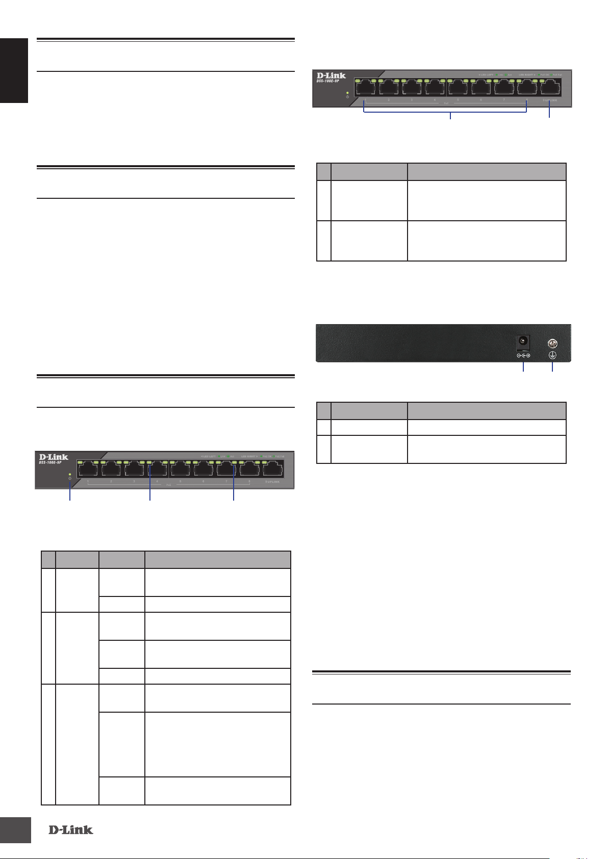
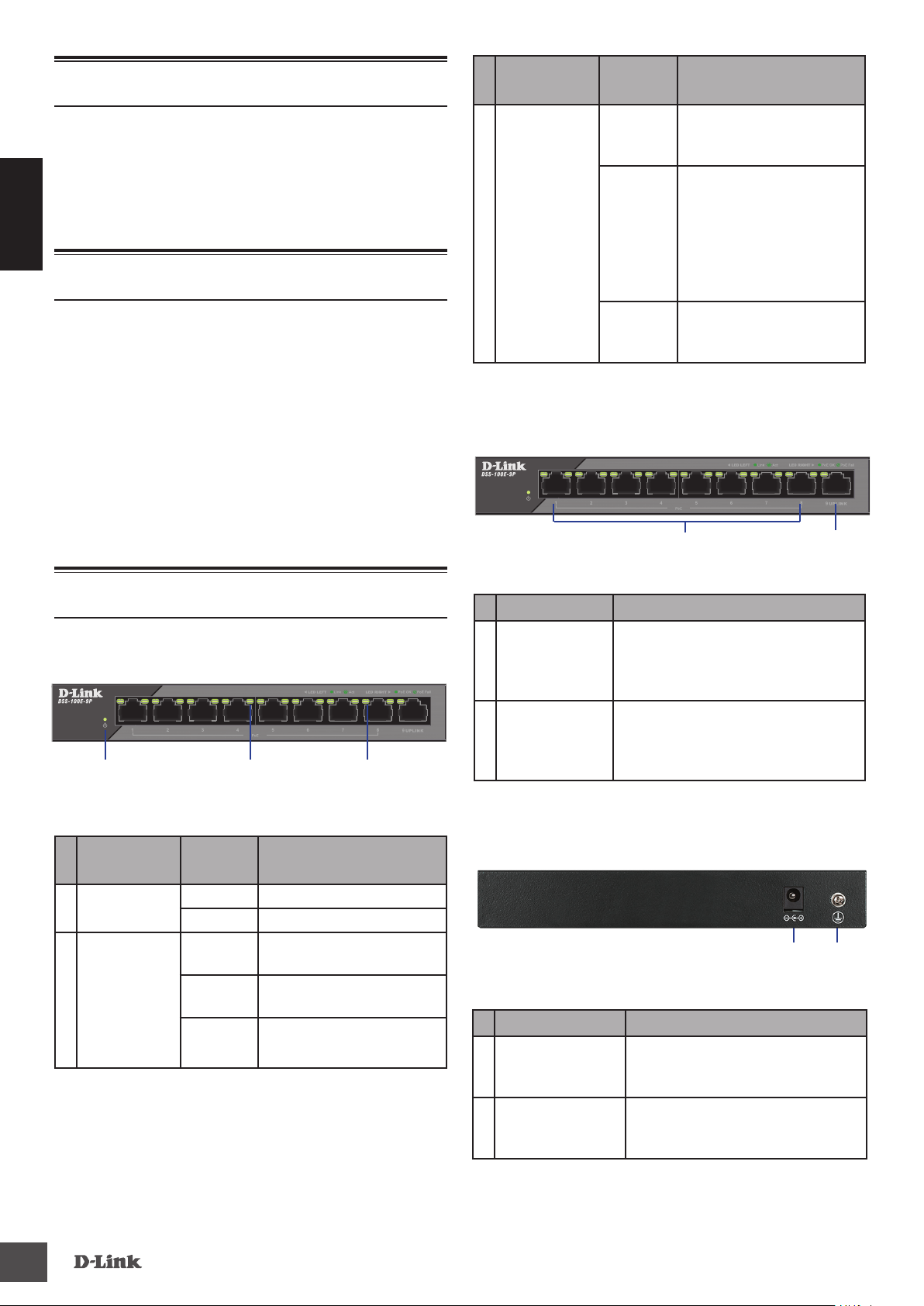
Front Panel Connectors
1
Figure 2: Front panel connectors
# Interface Description
10/100 Mbps PoE-capable ports,
1 Ports 1 - 8
2 Ports 9
Table 2: Front connector description
used for connecting Ethernet
devices and PoE-powered devices.
10/100/1000 Mbps Ethernet
port for uplink connections to
NVR, storage or core switch.
2
• 1 x Quick Installation Guide
If any of the above items are damaged or missing,
please contact your local D-Link reseller.
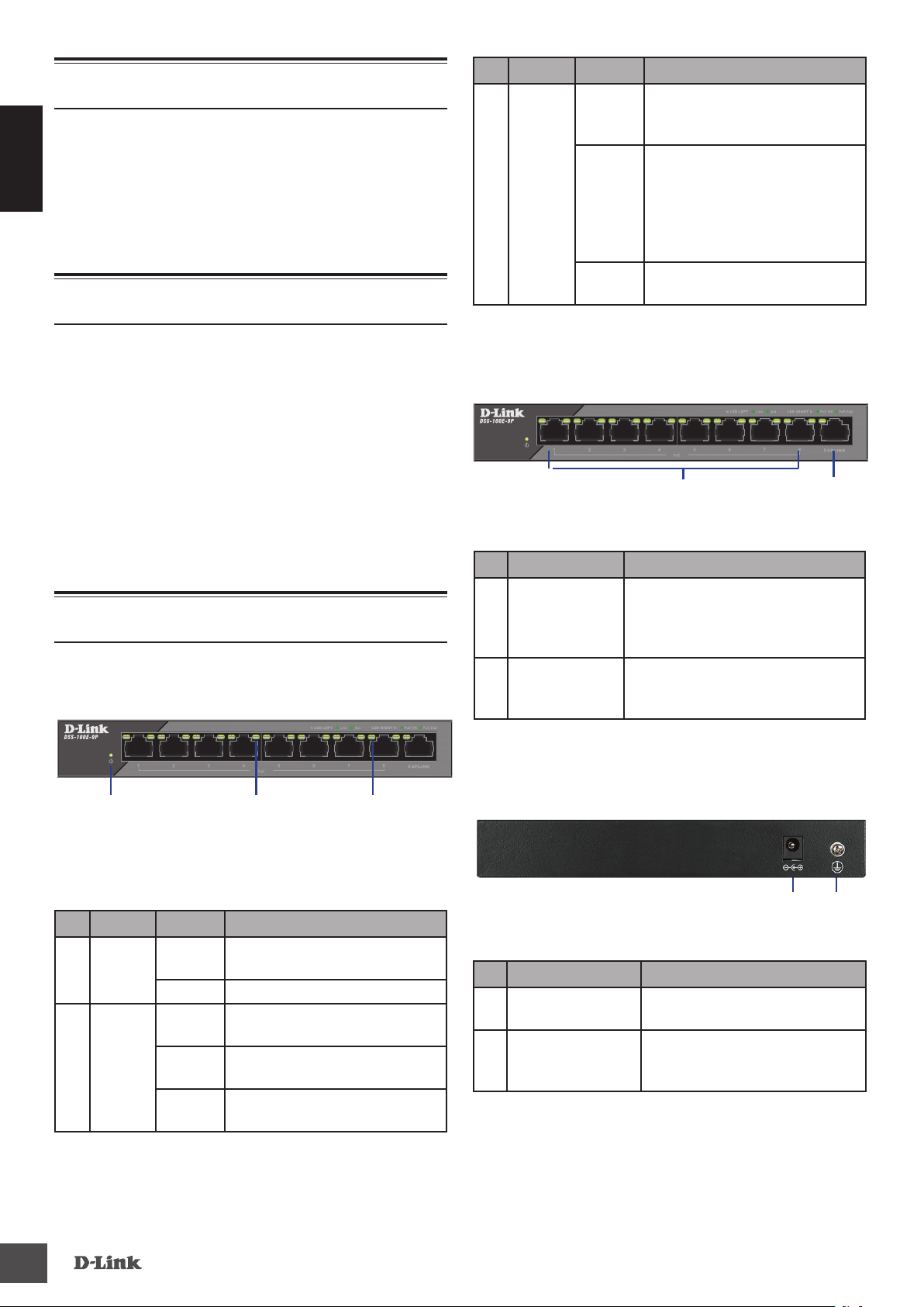
Hardware Overview
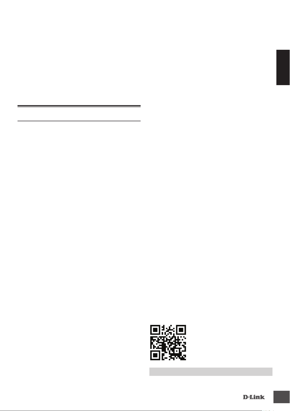
LED Indicators
1 2
Figure 1: Front panel LEDs
# LED Status Description
1 Power
Link/
ACT/
2
Speed
(Left
Led)
PoE
3
(Right
Led)
Solid
green
O The switch is turned o.
Solid
green
Blinking
green
O There is no active link on this port.
Solid
green
Blinking
green
O There is no PoE-powered device
The switch is powered on.
There is an active link negotiated
on this port.
There is trac on the port.
The port is providing power to the
connected PoE-powered device.
Indicates a PoE-powered device
is connected to this PoE port,
but the switch has insufficient
remaining power budget to
power the device.
connected to this port.
3
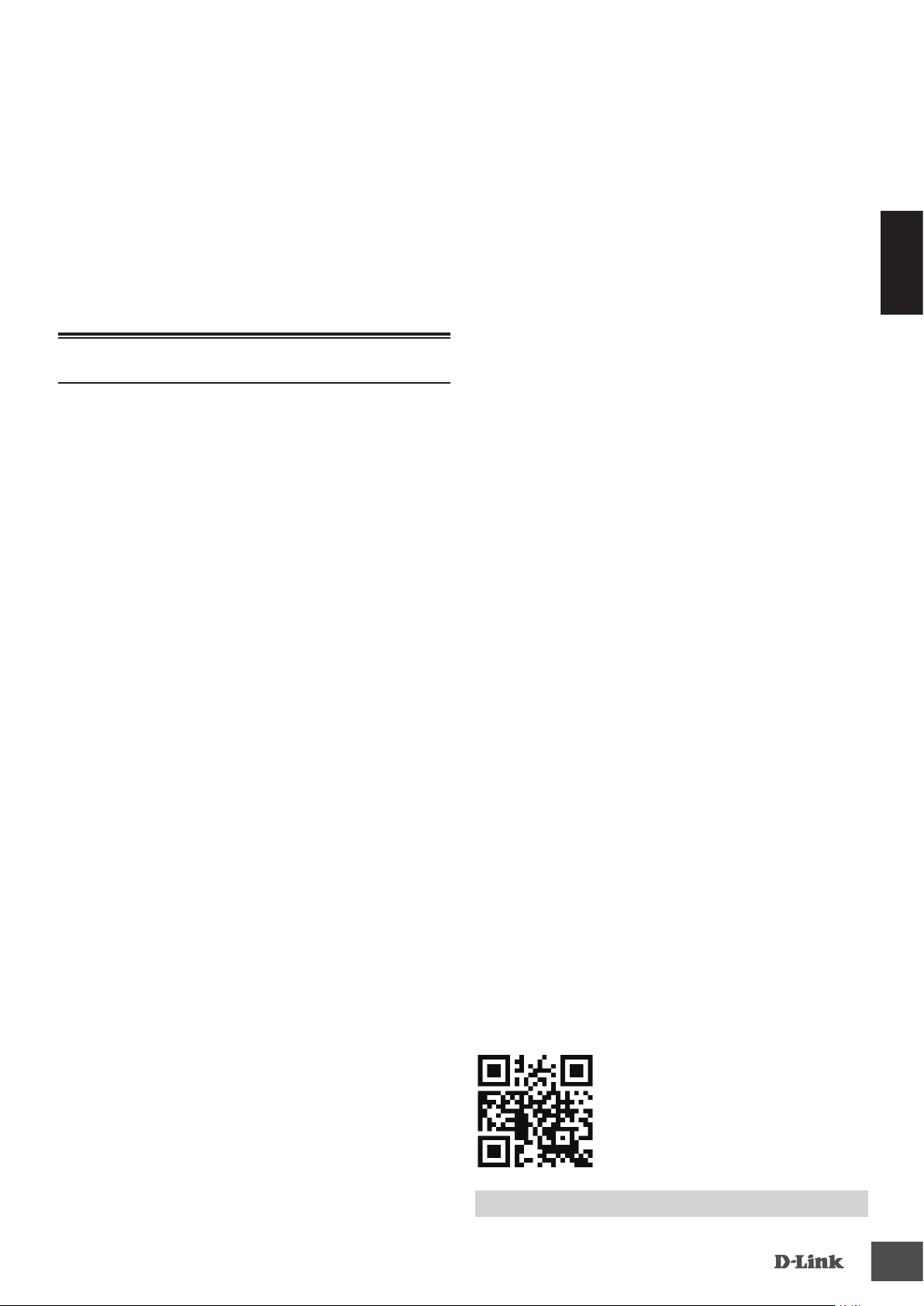
Rear Panel Connectors
Figure 3: Rear panel connectors
# Connector Description
1 DC Power Input Input jack for the power adapter.
2 SWITCH GND
Table 3: Rear connector description
Screw used to secure a grounding
wire to connect the switch to ground.
1 2
Extended Mode
The DSS-100E-9P can automatically detect the long
reach requirement and activate Extended without
manual conguration.
P.S. The actual transmission distance will be aected
by cable quality or connected IP Camera design. The
device can support up to 250m application with
Cat5e above ethernet cable, but the transmission
may drop to 10Mbps speed or below.
Hardware Installation
Installation Precautions
For safe switch installation and operation, it is
recommended to:
Table 1: LED overview
2
DSS-100E-9P
Page 3

• Visually inspect the DC power jack and make sure
that it is fully secured to the power adapter.
• Make sure that there is proper heat dissipation
and adequate ventilation around the switch.
• Install the switch in a site free from strong
electromagnetic sources, vibration, dust, and
direct sunlight.
• Not place heavy objects on the switch.
Grounding the Switch
The following steps explain the procedure for
connecting the switch to a protective ground:
1. Verify that the system is powered o.
2. Remove the ground screw and place the #8
terminal lug ring at one end of the ground cable
on top of the ground screw opening.
3. Insert the ground screw back into the ground
screw opening.
ENGLISH
4. Using a screwdriver, tighten the ground screw to
secure the ground cable to the switch.
5. Attach the terminal lug ring at the other end
of the grounding cable to an appropriate
grounding source.
6. Verify that the connections from the ground
connector on the switch to the grounding source
are securely attached.
Powering On the Switch
After connecting the switch to the network using
a compatible category 5/6/7 UTP network cable,
simply connect the switch to a power outlet to power
the device.
TECHNICAL SUPPORT
DSS-100E-9P
dlink.com/support
3
Page 4
Vor der Inbetriebnahme
In dieser Installationsanleitung erhalten Sie
schrittweise Anweisungen zur Einrichtung Ihres
DSS-100E-9P 9-port 10/100 PoE Surveillance Switch.
DEUTSCH
Beachten Sie, dass das von Ihnen erworbene Modell
sich möglicherweise geringfügig von denen der
Abbildungen unterscheidet.
Packungsinhalt
Dieses DSS-100E-9P-Paket muss Folgendes enthalten:
Nr. LED Status Beschreibung
3
PoE
(Rechte
LED)
Konstant
grün
Grün
blinkend
Aus An diesem Port ist kein PoE-
Tabelle 1: LED-Übersicht
Das über PoE gespeiste
angeschlossene Gerät wird über
den Port mit Strom versorgt.
Zeigt an, dass ein PoE-gespeistes
Gerät an diesem PoE-Port
angeschlossen, das verbleibende
Strombudget des Switch für die
Versorgung des Geräts aber nicht
ausreichend ist.
gespeistes Gerät angeschlossen.
• 1 x DSS-100E-9P
• 1 x Netzkabel
• 1 x Netzteil
• 1 x Installationsanleitung
Sollte eines der oben aufgeführten Teile beschädigt
sein oder fehlen, wenden Sie sich bitte an Ihren
D-Link-Händler vor Ort.
Hardware-Übersicht
LED-Anzeigen
1 2
3
Anschlüsse an der Vorderseite
1
Abbildung 2: Anschlüsse an der Vorderseite
Nr. Schnittstelle Beschreibung
10/100 Mbit/s PoE-fähige Ports,
1 Ports 1 - 8
2 Port 9
Tabelle 2: Beschreibungen der vorderen Anschlüsse
verwendet für den Anschluss
von Ethernet-Geräten und
PoE-betriebenen Geräten.
10/100/1000 Mbit/s Ethernet-Port
für Uplink-Verbindungen zu NVR,
Speichergerät oder Core-Switch.
Anschlüsse an der Rückseite
2
Abbildung 1: Vorderseite LEDs
Nr. LED Status Beschreibung
1 Strom
Link/
ACT/
2
Speed
(Linke
LED)
Konstant
grün
Aus Der Switch ist ausgeschaltet.
Konstant
grün
Grün
blinkend
Aus An diesem Port besteht keine
Der Switch ist eingeschaltet.
Für diesen Port ist eine aktive
Verknüpfung gewählt.
Über den Port wird Datenverkehr
geleitet.
aktive Verbindung.
4
1 2
Abbildung 3: Anschlüsse an der Rückseite
Nr. Anschluss Beschreibung
1
Stromversorgung
2 SWITCH GND
Tabelle 3: Beschreibungen der hinteren Anschlüsse
DC-
Buchse zum Anschließen des
Netzteils.
Schraube zum Anschließen eines
Erdungsdrahts zum Verbinden
des Switch mit Erde.
DSS-100E-9P
Page 5
Erweiterter Modus
Der DSS-100E-9P kann die Anforderungen an eine
lange Reichweite automatisch erkennen und den
Erweiterten Modus ohne manuelle Konguration
aktivieren.
P.S.: Die tatsächliche Übertragungsdistanz ist von der
Kabelqualität oder dem Design der angeschlossenen
IP-Kamera abhängig. Das Gerät kann bis zu 250 m
mit Cat5e über Ethernet-Kabel unterstützen, die
Übertragungsgeschwindigkeit kann jedoch auf 10
Mbit/s oder weniger sinken.
Hardware-Installation
Sicherheitshinweise für die Installation
Um eine sichere Installation und einen sicheren
Betrieb zu gewährleisten, wird Folgendes empfohlen:
5. Bringen Sie den Ringkabelschuh am anderen
Ende des Erdungskabels an einer geeigneten
Erdungseinrichtung an.
6. Überprüfen Sie, dass die Verbindungen vom
Erdungsanschluss am Switch zur Erdungsquelle
sicher angebracht sind.
Stromversorgung des Switch
Schließen Sie den Switch, nachdem Sie ihn mit einem
kompatiblen UTP-Netzwerkkabel der Kategorie
5/6/7 mit dem Netzwerk verbunden haben, einfach
an eine Steckdose an, um ihn mit Strom zu versorgen.
DEUTSCH
• Vergewissern Sie sich, dass das Netzteilkabel fest
in die Stromeingangsbuchse eingesteckt ist.
• Achten Sie darauf, dass eine korrekte
Wärmeableitung und eine ausreichende
Belüftung um den Switch gewährleistet sind.
• Installieren Sie den Switch an einem Ort, an dem
er keinen starken elektromagnetischen Quellen,
Vibrationen, Staub und direktem Sonnenlicht
ausgesetzt ist.
• Stellen Sie keine schweren Gegenstände auf den
Switch.
Erdung des Switch
In den folgenden Schritten wird das Anschließen des
Switch an eine Schutzerde erläutert:
1. Vergewissern Sie sich, dass das System
ausgeschaltet ist.
2. Entfernen Sie die Erdungsschraube und platzieren
Sie den Ringkabelschuh Nr. 8 an einem Ende
des Erdungskabels, oberhalb der Önung der
Erdungsschraube.
3. Setzen Sie die Erdungsschraube wieder in die
Önung für die Erdungsschraube ein.
4. Ziehen Sie die Erdungsschraube mithilfe eines
Schraubendrehers fest, um das Erdungskabel
am Switch zu befestigen.
DSS-100E-9P
TECHNISCHER SUPPORT
dlink.com/support
5
Page 6
Avant de commencer
Ce guide d'installation rapide vous fournit des
instructions pas à pas pour la conguration de votre
commutateur de surveillance PoE 10/100 à 9 ports
DSS-100E-9P. Le modèle que vous avez acheté peut
légèrement diérer de celui illustré.
FRANÇAIS
Contenu de la boîte
Cette boîte DSS-100E-9P doit comprendre les
éléments suivants:
# Voyant
lumineux
PoE
3
(voyant de
droite)
État Description
Vert xe Le por t fournit l'alimentation
au périphérique connecté
alimenté via PoE.
Vert
clignotant
Désactivé Il n'existe pas de
Indique qu'un périphérique
alimenté par PoE est
connecté à ce port PoE, mais
le commutateur n'a pas
un budget d'alimentation
susant pour alimenter le
périphérique.
périphérique alimenté via
PoE sur ce port.
• 1 x DSS-100E-9P
• 1 x cordon d'alimentation
• 1 x adaptateur d'alimentation
• 1 x Guide d'installation rapide
Si l'un des éléments ci-dessus est endommagé ou
manquant, contactez votre revendeur local D-Link.
Vue d'ensemble du matériel
Voyants lumineux
1 2 3
Figure 1: Voyants de la façade
Tableau 1: Présentation des voyants
Connecteurs de façade
1 2
Figure 2: Connecteurs de façade
# Interface Description
Ports 10/100 Mbits/s compatibles
1 Ports 1 - 8
2 Port 9
Tableau 2: Description des connecteurs de façade
PoE, utilisés pour connecter des
périphériques Ethernet et des
périphériques alimentés via PoE.
Port Ethernet 10/100/1000 Mbps
pour les connexions de liaison
montante au NVR, au stockage
ou au commutateur principal.
# Voyant
1 Alimentation
2
6
lumineux
Link/ACT/
Speed
(Liaison/
Activité/
Vitesse)
(voyant de
gauche)
État Description
Vert xe Le commutateur est allumé.
Désactivé Le commutateur est éteint.
Vert xe Il existe une liaison active
négociée sur ce port.
Vert
clignotant
Désactivé Il n'y a pas de liaison active
Ce port présente du trac.
sur ce port.
Connecteurs du panneau arrière
1 2
Figure 3: Connecteurs du panneau arrière
# Connecteur Description
Entrée
1
d'alimentation
CC
MISE À LA
2
TERRE DU
COMMUTATEUR
Tableau 3: Description des connecteurs du panneau
Prise d'entrée pour l'adaptateur
secteur.
Vis utilisée pour xer un câble de
mise à la terre pour raccorder le
commutateur à la terre.
arrière
DSS-100E-9P
Page 7
Mode Prolongateur
Le DSS-100E-9P peut détecter automatiquement
les exigences de longue portée et activer le mode
prolongateur sans conguration manuelle.
P.S. La distance de transmission réelle est aectée par
la qualité du câble ou la conception de la caméra IP
connectée. Le périphérique peut prendre en charge
une utilisation jusqu’à 250 m avec un câble Ethernet
supérieur à la catégorie Cat5e, mais la transmission
peut chuter à une vitesse de 10 Mbps ou moins.
Installation du matériel
Précautions d'installation
Pour une installation et une utilisation sûres du
commutateur, les points suivants sont recommandés:
5. Fixez l'anneau de cosse de l'autre extrémité du
câble de mise à la terre à la source appropriée de
mise à la terre.
6. Vériez que les raccordements entre le connecteur
de mise à la terre du commutateur et la source
de mise à la terre sont fermes.
Mise sous tension du commutateur
Après avoir connecté le commutateur au réseau à
l'aide d'un câble réseau compatible de catégorie
5/6/7 UTP, branchez simplement le commutateur
sur une prise de courant pour alimenter l'appareil.
FRANÇAIS
• Inspectez visuellement la prise d'alimentation CC
et assurez-vous qu'il est fermement connecté à
l'adaptateur secteur.
• Veillez à assurer une dissipation appropriée de
la chaleur et une bonne ventilation autour du
commutateur.
• Installez le commutateur dans un endroit exempt
de sources de champs électromagnétiques
intenses, de vibrations, de poussière et à l'abri
des rayons du soleil.
• Ne placez pas des objets lourds sur le
commutateur.
Mise à la terre du commutateur
Les étapes suivantes explique la procédure de
raccordement du commutateur à la terre en guise
de protection:
1. Vériez que le système est hors tension.
2. Retirez la vis de mise à la terre et placez l'anneau
de la cosse n°8 à une extrémité du câble de mise
à la terre, en haut de l'ouverture pour la vis de
mise à la terre.
3. Réinsérez la vis de mise à la terre dans l'ouverture
correspondante.
4. Utilisez un tournevis pour serrer la vis de mise à
la terre an de xer le câble de mise à la terre au
commutateur.
DSS-100E-9P
SUPPORT TECHNIQUE
dlink.com/support
7
Page 8

Antes de empezar
Esta guía de instalación rápida le ofrece instrucciones
paso a paso para configurar el conmutador de
vigilancia PoE 10/100 de 9 puertos DSS-100E9P. El modelo que ha adquirido puede tener un
aspecto ligeramente diferente al mostrado en las
ilustraciones.
ESPAÑOL
Contenido de la caja
La caja de este DSS-100E-9P debe incluir los
elementos siguientes:
• 1 DSS-100E-9P
• 1 cable de alimentación
# LED Estado Descripción
3
Verde
continuo
Verde
intermitente
PoE
(Led rojo)
Des. No hay ningún
Tabla 1: Visión general de los LED
El puerto proporciona
alimentación al
dispositivo conectado y
alimentado por PoE.
Indica que un dispositivo
alimentado por PoE
está conectado a este
puerto PoE, pero al
conmutador no le queda
una asignación eléctrica
suficiente como para
alimentar al dispositivo.
dispositivo alimentado
por PoE que esté
conectado a este puerto.
• 1 adaptador de corriente
• 1 guía de instalación rápida
Si cualquiera de los artículos anteriores falta o está
dañado, póngase en contacto con su proveedor
local de D-Link.
Descripción general del hardware
In- dicadores LED
1 2 3
Figura 1: LED del panel frontal
# LED Estado Descripción
1 Alimentación
Enlace/ACT./
Velocidad
2
(Led
izquierdo)
Verde
continuo
Des. El conmutador está
Verde
continuo
Verde
intermitente
Des. No hay ningún enlace
El conmutador está
encendido.
apagado.
Hay un enlace activo
negociado en este
puerto.
Hay tráco en el puerto.
activo en este puerto.
Conectores del panel frontal
1
Figura 2: Conectores del panel frontal
# Interfaz Descripción
Puertos con capacidad PoE de
1 Puertos 1 a 8
2 Puerto 9
Tabla 2: Descripción de los conectores delanteros
10/100 Mbps, usados para la
conexión de dispositivos Ethernet y
dispositivos alimentados por PoE.
Puerto Ethernet 10/100/1000
Mbps para conexiones de enlace
ascendente a NVR, almacenamiento
o conmutador central.
Conectores del panel posterior
1 2
Figura 3: Conectores del panel posterior
# Conector Descripción
Entrada de
1
alimentación
CC
TOMA DE
2
TIERRA DEL
CONMUTADOR
Toma de entrada para el adaptador de
alimentación.
Tornillo que se usa para asegurar un
cable de toma de tierra para conectar
el conmutador a tierra.
2
Tabla 3: Descripción de los conectores traseros
8
DSS-100E-9P
Page 9
Modo extendido
El DSS-100E-9P puede detectar automáticamente
el requisito de largo alcance y activar el modo
extendido sin necesidad de conguración manual.
Nota. La distancia de transmisión real se verá
afectada por la calidad del cable o por el diseño de
la cámara IP conectada. El dispositivo puede admitir
una aplicación de hasta 250 m con Cat5e sobre el
cable Ethernet, pero la transmisión podría caer hasta
una velocidad de 10 Mbps o inferior.
Instalación del hardware
Precauciones durante la instalación
Para conseguir una instalación y funcionamiento
seguros del conmutador, se recomienda que haga
lo siguiente:
6. Compruebe que las conexiones del conector
de tierra en el conmutador y en la fuente de
conexión a tierra están acopladas rmemente.
Encendido del conmutador
Después de conectar el conmutador a la red mediante
un cable de red compatible UTP de categoría 5/6/7,
solo tendrá que conectar el conmutador a una toma
de corriente para alimentar el dispositivo.
ESPAÑOL
• Inspeccione visualmente la clavija de alimentación
CC y asegúrese de que esté totalmente asentada
en el adaptador de alimentación.
• Asegúrese de que existe una disipación correcta
del calor y ventilación adecuada alrededor del
conmutador.
• Instale el conmutador en un lugar en el que
no existan fuentes electromagnéticas intensas,
vibraciones, polvo ni luz solar directa.
• No coloque objetos pesados sobre el conmutador.
Conexión a tierra del conmutador
En los pasos siguientes se explica el procedimiento
para conectar el conmutador a una toma de tierra
de protección:
1. Compruebe que el sistema está apagado.
2. Retire el tornillo de toma de tierra y coloque el
aro de orejeta del terminal n.º 8 en un extremo
del cable de tierra, en la parte superior de la
apertura del tornillo de tierra.
3. Inserte de nuevo el tornillo de conexión a tierra
en la abertura del tornillo de conexión a tierra.
4. Utilizando un destornillador, apriete el tornillo de
conexión a tierra para jar el cable de conexión
a tierra al conmutador.
5. Acople el aro de orejeta del terminal situado en
el otro extremo del cable de conexión a tierra a
una conexión a tierra adecuada.
DSS-100E-9P
ASISTENCIA TÉCNICA
dlink.com/support
9
Page 10

Prima di iniziare
In questa Guida per l'installazione rapida sono
riportate istruzioni dettagliate per congurare lo
switch DSS-100E-9P 9-port 10/100 PoE Surveillance.
Il modello acquistato potrebbe essere leggermente
diverso da quello ragurato nelle illustrazioni.
Contenuto della confezione
Questo DSS-100E-9P pacchetto deve includere i
seguenti elementi:
ITALIANO
• 1 x DSS-100E-9P
# LED Stato Descrizione
Verde sso La porta fornisce
alimentazione al
dispositivo alimentato
da PoE collegato.
3
(Led destro)
PoE
Verde
lampeggiante
O Nessun dispositivo PoE
Tabella 1: Panoramica LED
Indica che un dispositivo
alimentato PoE è
connesso a questa porta
PoE, ma l'alimentazione
disponibile restante dello
switch è insuciente per
accendere il dispositivo.
connesso a questa porta.
• 1 x cavo di alimentazione
• 1 x Adattatore alimentazione
• 1 x Guida di installazione rapide
Se uno o più degli articoli sopra elencati risultano
danneggiati o mancanti, contattare il rivenditore
D-Link locale.
Panoramica hardware
Indicatori LED
1 2 3
Figura 1: LED del pannello frontale
Connettori pannello frontale
1 2
Figura 2: Connettori pannello frontale
# Interfaccia Descrizione
Porte basate su PoE 10/100 Mbps,
1 Porte 1 - 8
2 Porte 9
Tabella 2: Descrizione connettore anteriore
usate per la connessione di
dispositivi Ethernet e dispositivi
con alimentazione PoE.
Porta Ethernet 10/100/1000 Mbps
per connessioni uplink a NVR,
archiviazione o switch core.
Connettori pannello posteriore
# LED Stato Descrizione
1 Accensione
Link/ACT/
Speed
2
(Led
sinistro)
Verde sso Lo switch è acceso.
O Lo switch è spento.
Verde sso In questa porta è presente
un collegamento attivo
negoziato.
Verde
lampeggiante
O Nessun link attivo su
Traco sulla porta.
questa porta.
10
Figura 3: Connettori pannello posteriore
# Connettore Descrizione
Ingresso di
1
alimentazione
CC
2 SWITCH GND
Tabella 3: Descrizione connettore posteriore
Jack di ingresso per l'adattatore di
alimentazione.
Vite usata per ssare un lo di messa a
terra e collegare l'interruttore a terra.
1 2
DSS-100E-9P
Page 11

Modalità extender
DSS-100E-9P consente di rilevare automaticamente
il requisito di ricerca prolungata e di attivare
l'estensione senza congurazione manuale.
P.S. La distanza di trasmissione effettiva sarà
interessata dalla qualità del cavo o dal design della
telecamera IP connessa. Il dispositivo supporta
un'applicazione no a 250 m con Cat5e sopra il cavo
Ethernet, ma la trasmissione potrebbe scendere a 10
Mbps di velocità o meno.
Installazione dell'hardware
Precauzioni per l'installazione
Per un’installazione e un funzionamento sicuri dello
switch, si consiglia di:
6. Vericare che i collegamenti del connettore di
messa a terra nello switch alla fonte di messa
a terra siano agganciati correttamente.
Accensione dello switch
Dopo avere collegato lo switch alla rete utilizzando
un cavo di rete UTP di categoria 5/6/7 compatibile,
sarà suciente collegare lo switch a una presa di
alimentazione per accendere il dispositivo.
ITALIANO
• Controllare visivamente il jack di alimentazione
CC e vericare che sia completamente ssato
all'adattatore di alimentazione.
• Vericare che la dissipazione di calore sia corretta
e che la ventilazione sia adeguata attorno allo
switch.
• Installare lo switch in un luogo non soggetto
a forti campi elettromagnetici, lontano da
vibrazioni, polvere e luce diretta del sole.
• Non collocare oggetti pesanti sullo switch.
Messa a terra dello switch
I seguenti passaggi descrivono la procedura di
collegamento dello switch a una messa a terra di
protezione:
1. Vericare che il sistema sia spento.
2. Rimuovere la vite di messa a terra e posizionare
il capocorda con anello #8 ad una estremità
del cavo di messa a terra, sulla parte superiore
dell'apertura della vite di messa a terra.
3. Re-inserire la vite di messa a terra nell'apposita
apertura.
4. Utilizzando un cacciavite, serrare la vite di messa
a terra per ssare il cavo di messa a terra allo
switch.
5. Agganciare il capocorda ad anello all'altra
estremità del cavo di messa a terra a un'apposita
fonte di messa a terra.
DSS-100E-9P
ASSISTENZA TECNICA
dlink.com/support
11
Page 12

Ver. 1.01(EU)_130X183
2020/05/21
 Loading...