

Page 1
D-Link Diagnostics Utility User Guide
D-Link Diagnostics Utility User Guide
1. Using the Diagnostics Utility software
(This utility is only for Windows 2000 and XP )
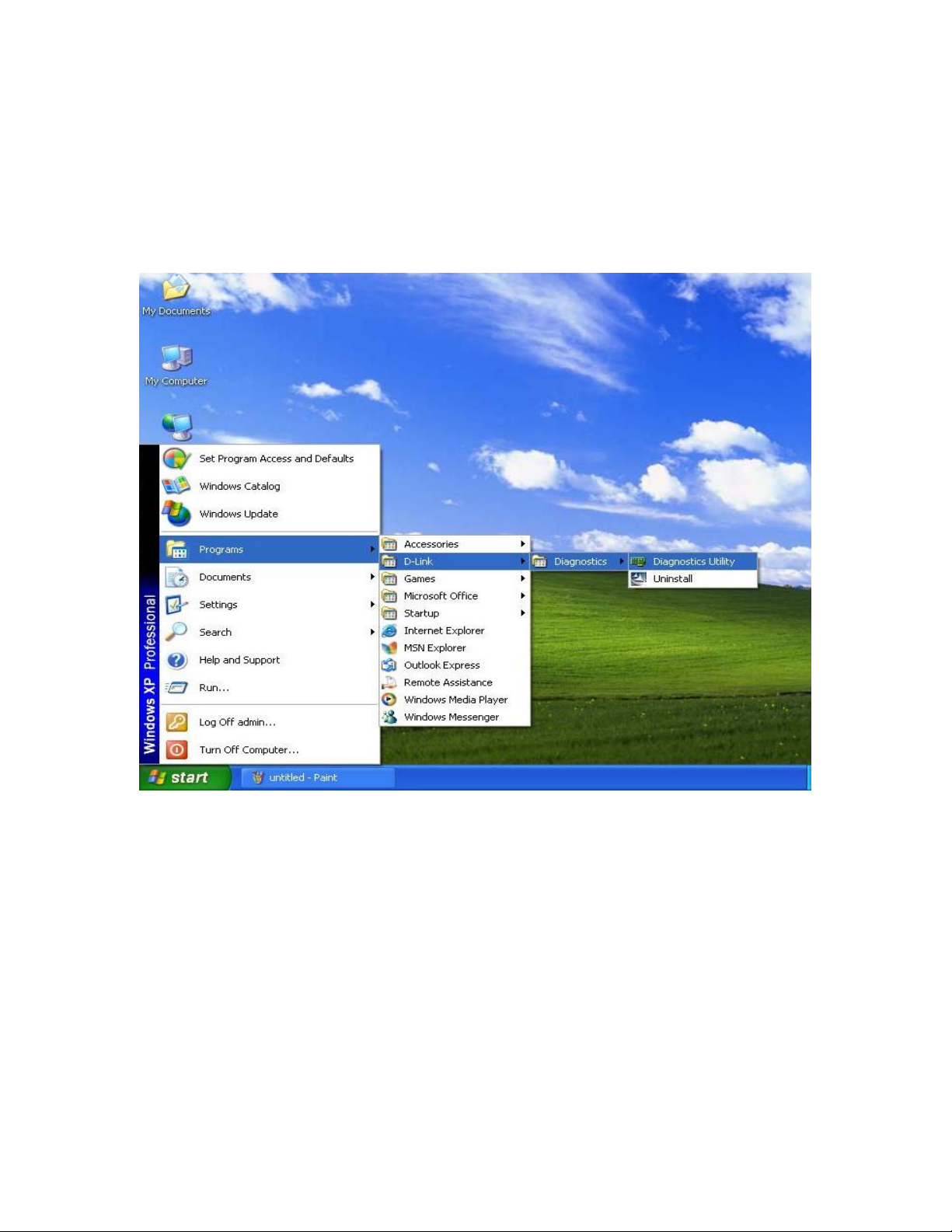
1.1 Start the Utility software
From the start up menu, left click the icon in Programs->D-Link->Diagnostics Utility, as
shown in the figure below:
1
Page 2
D-Link Diagnostics Utility User Guide
1.2 Functions
The utility provides 7 main functions, such as “General”, “VLAN”, “Driver”,
“Diagnostics”, “Statistics”, “Cable” and “Wake On LAN” which are explained in more
details in the following sections.
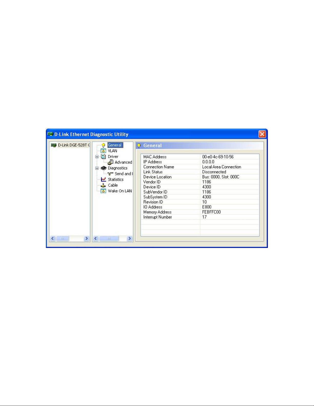
1.2.1 General
The General section provides the general information about this Ethernet card, including
“MAC Address”, “IP Address”, “Connection Name”, “Link Status”, “Device Location”,
“Vendor ID”, “Device ID”, “SubVendor ID”, “SubSystem ID”, “Revision ID”, “IO
Address”, “Memory Address” and “Interrupt Number”. An example is shown in the
figure below:
2
Page 3
D-Link Diagnostics Utility User Guide
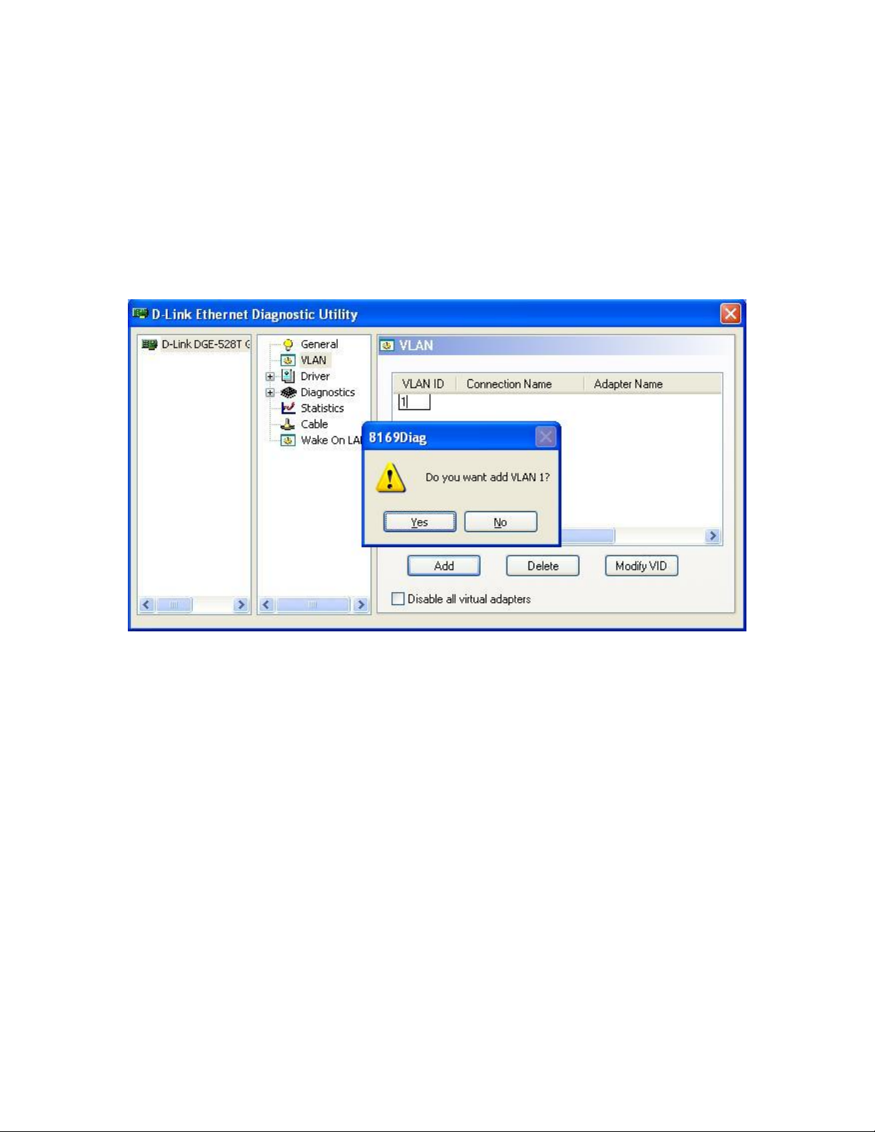
1.2.2 VLAN
The VLAN section provides the management functions for user to maintain any Virtual
Adapters related to this Ethernet card. There are 4 functions: Add, Delete, Modify and
Disable all VLAN.
1.2.2.1 Add a new VLAN
Click the Add button, type in the “VLAN ID” and press Enter, a prompt will show for
confirmation, click yes.
3
Page 4
D-Link Diagnostics Utility User Guide
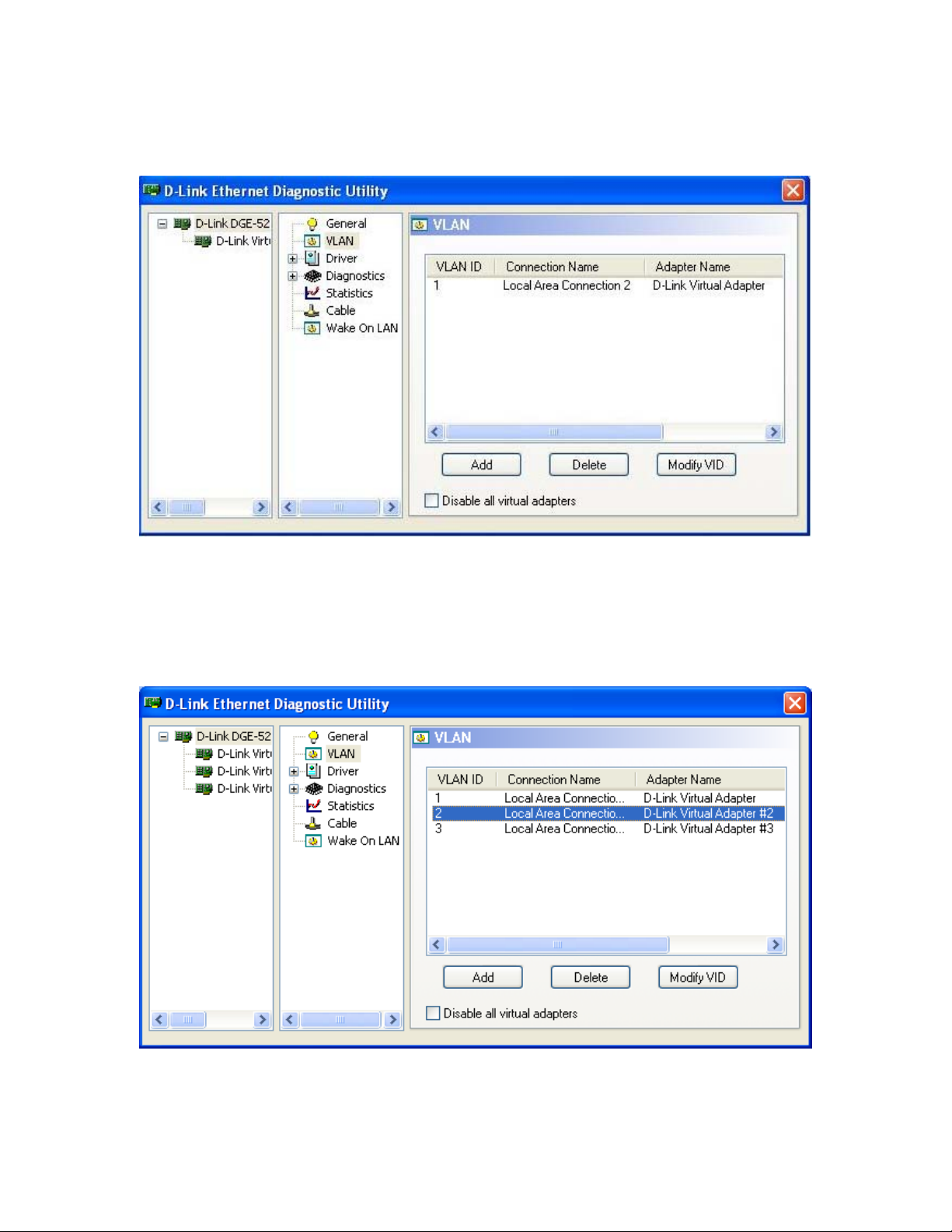
A new Virtual adapter will be installed; the utility display will be refreshed and updated.
The new added VLAN will be listed in the VLAN section as shown in the following
figures.
Note: 1. VLAN id must be numbers ranged between 1 and 4096
2. The maximum number of VLAN allowed is 64
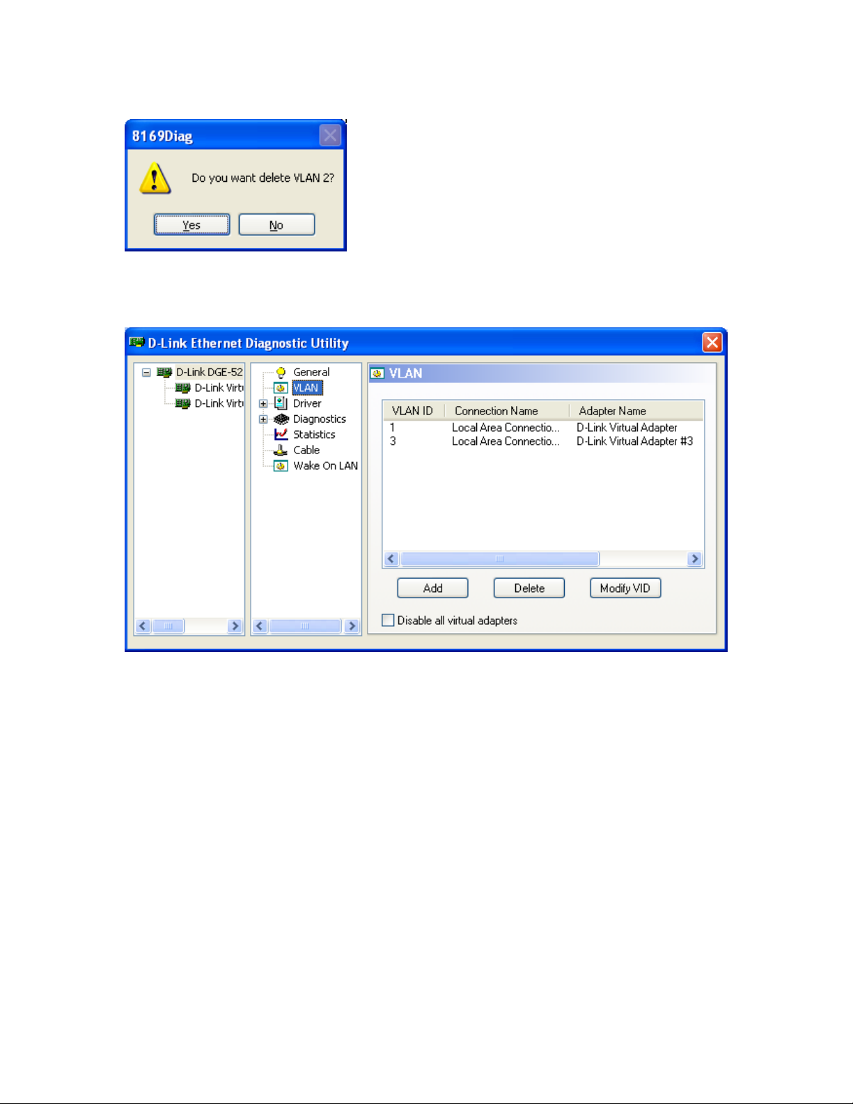
1.2.2.2 Delete an existing VLAN
1.Select the VLAN from the list (e.g. VALN ID 2)
4
Page 5
D-Link Diagnostics Utility User Guide
2.Click Delete, and press Yes in the confirmation prompt.
3.The selected Virtual adapter will be removed; the utility display will be refreshed and
updated. The remaining VLAN will be listed in the VLAN section as shown in the
following figures.
5
Page 6
D-Link Diagnostics Utility User Guide
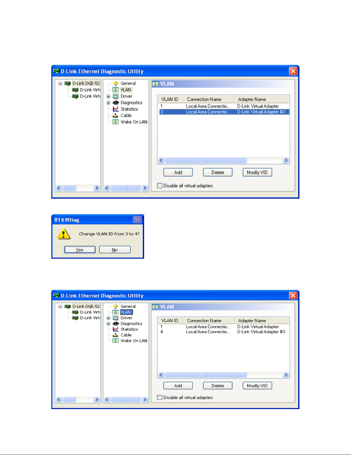
1.2.2.3 Modifying an existing VLAN
1. Select the VLAN from the list (e.g. VALN ID 3)
2. Click Modify VID, change the VLAN id and press Yes in the confirmation prompt.
3.The selected VLAN id will be modified; the utility display will be refreshed and
updated. The modified VLAN will be listed in the VLAN section as shown in the
following figures
6
Page 7

D-Link Diagnostics Utility User Guide
1.2.2.4 Disable all virtual adapters
Tick the “Disable all virtual adapters” checkbox; all virtual adapters will be disabled.
All virtual adapters can be enabled by simply un-tick the checkbox.
7
Page 8

D-Link Diagnostics Utility User Guide
1.2.3 Driver
The Driver section listed the information about the Driver including “Description”,
“Provider”, “Version”, “Date”, “INF Path” and “Binary Path”.
8
Page 9

D-Link Diagnostics Utility User Guide
1.2.3.1 Advanced Setting
Properties available for this network adapter can be changed in the Advanced Setting
section. Those properties include “Flow Control”, “Jumbo Frame”, “Link Speed/Duplex
Mode”, Network Address”, “Offload Checksum”, and “Offload TCP_LargeSend”.
1.2.3.1.1 Flow Control
Flow control can be set to enable or disable.
1.2.3.1.2 Jumbo Frame
Jumbo Frame size can be set from 2KB MTU up to 7KB MTU.
9
Page 10
D-Link Diagnostics Utility User Guide
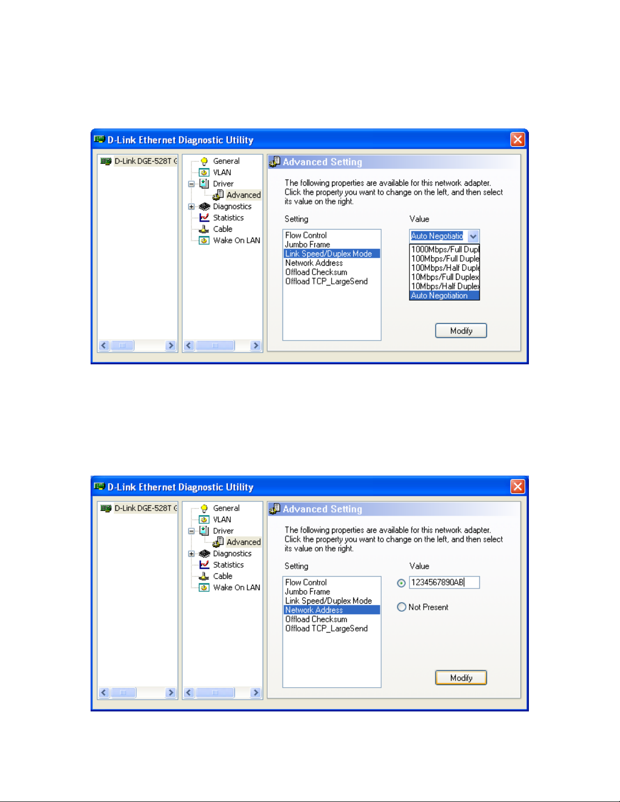
1.2.3.1.3 Link Speed / Duplex Mode
The Link Speed / Duplex Mode can be set to a range of combinations as shown in the
figure below:
1.2.3.1.4 Network Address
The Network Address can be modified by type in a new network address in the Value
field and press Modify.
The following figure demonstrates the modification of the Network
Address to “1234567890AB”
10
Page 11

D-Link Diagnostics Utility User Guide
As shown in the following figure, the MAC Address has been changed to 12-34-56-7890-ab
1.2.3.1.5 Offload Checksum
The options available for Offload Checksum are “Tx/Rx Checksum”, “Tx Checksum”,
“Rx Checksum” and “Disable”.
11
Page 12

D-Link Diagnostics Utility User Guide
1.2.3.1.6 Offload TCP_LargeSend
The Offload TCP_LargeSend property can be set to Enable or Disable in this section.
12
Page 13

D-Link Diagnostics Utility User Guide
1.2.4 Diagnostics
The diagnostics tool tests the Register, EEPROM and Loopback functions.
To start the test, user should tick the items, and press “Start Test” button.
The following figure shows the result of a single test run.
13
Page 14

D-Link Diagnostics Utility User Guide
User could also tick the “Repeat” option, which would repeat the tests until the “Stop
Test” button is pressed.
1.2.4.1 Send and Receive
This function tests the send and receive ability of this network adapter, it requires two
computer both installed this Utility, one computer should acts as the Initiator by tick the
Initiator option, the other computer should tick the Responder option. Then both press the
Start button.
The following figure shows the result from the Initiator PC.
14
Page 15

D-Link Diagnostics Utility User Guide
The following figure shows the result from the Responder PC.
Note: The screen capture of the responder PC is taken later than the Initiator PC, thus the
numbers of Packet Sent and Received is greater than in the Initiator PC.
15
Page 16

D-Link Diagnostics Utility User Guide
1.2.5 Statistics
This section displays the real-time Throughput (Send, Receive and Total), Packet (Send,
Receive) and Error (Send, Receive) statistics.
1.2.6 Cable
This section lists the status of the Cable connected to this network adapter. The status for
a properly connected cable is displayed as “Normal”, it would also display the length of
the cable; The following figure shows the status of the Cable connecting between 2
Gigabit Ethernet adapters.
16
Page 17

D-Link Diagnostics Utility User Guide
If the cable is not properly connected, the “Open” status will be displayed, the following
figure shows the status of the Cable when it is not properly connected.
17
Page 18

D-Link Diagnostics Utility User Guide
1.2.7 Wake On LAN
This function provides 3 methods to Wake up a computer in the same network. These
methods are “Ethernet Address”, “IP Address” and “NetBIOS Name”.
1.2.7.1 Ethernet Address
To Wake up a computer that is in “Standby”/”Hibernate”/”Shutdown” mode, user could
type in the Ethernet Address of the computer that needs to be waken, and press “Wake
Up” button. ( e.g. To wake up a computer with Ethernet Address = 1234567890AB,
shown in the following figure )
18
Page 19

D-Link Diagnostics Utility User Guide
1.2.7.2 I.P. Address
To Wake up a computer that is in “Standby”/”Hibernate” mode, user could type in the
I.P. Address of the computer that needs to be waken, and press “Wake Up” button.
( e.g. To wake up a computer with I.P. Address = 192.168.1.2, shown in the following
figure )
1.2.7.3 NetBIOS Name
To Wake up a computer that is in “Standby”/”Hibernate” mode, user could type in the
NetBIOS Name of the computer that needs to be waken, and press “Wake Up” button.
( e.g. To wake up a computer with NetBIOS Name = TestPC, shown in the following
figure )
19
 Loading...