

Page 1

D-Link
DI-524UP
802.11g
Wireless Router
Manual
Building Networks for People
Ver 1.00
Page 2

Contents
Package Contents ..........................................................................................................iv
Introduction......................................................................................................................1
Connections.....................................................................................................................2
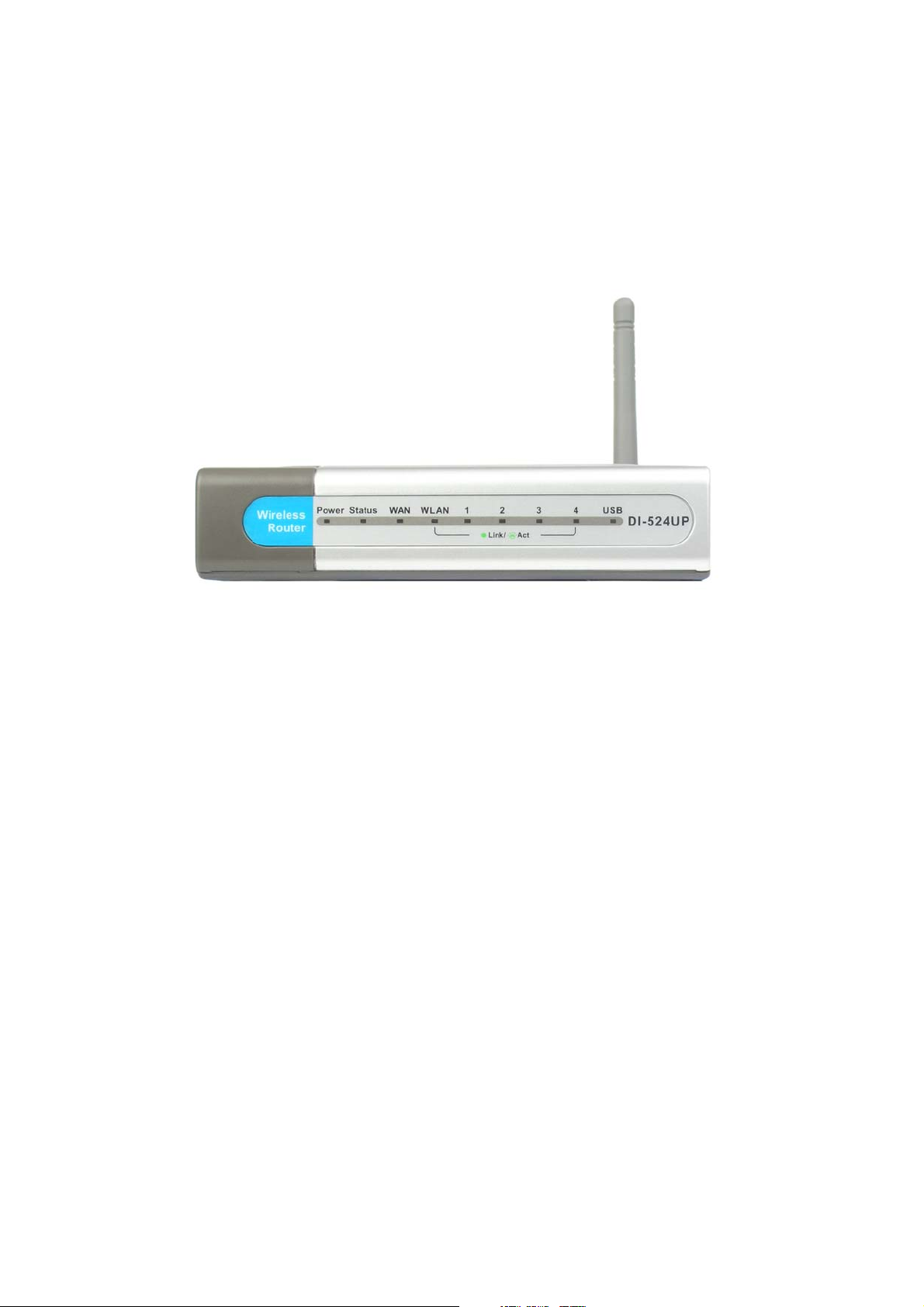
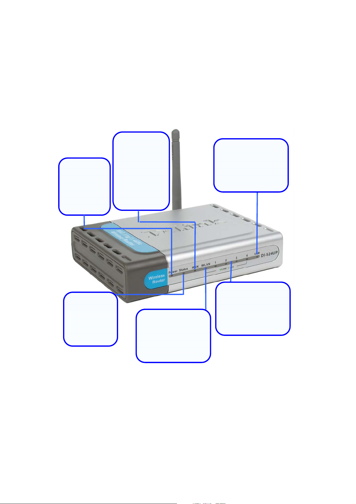
LEDs .................................................................................................................................3
Features............................................................................................................................4
Wireless Basics ...............................................................................................................6
Standards-Based Technology......................................................................................7
Installation Considerations ...........................................................................................7
Getting Started ................................................................................................................8
Using the Configuration Wizard................................................................................... 10
Home > Wireless........................................................................................................11
Home > WAN .............................................................................................................16
Home > LAN............................................................................................................... 24
Advanced > Virtual Server .........................................................................................25
Advanced > Applications............................................................................................28
Advanced > Filters .....................................................................................................29
Advanced > Parental Control .....................................................................................32
Advanced > Firewall...................................................................................................35
Advanced > DMZ .......................................................................................................37
Advanced > DDNS .....................................................................................................38
Advanced > QoS ........................................................................................................40
Advanced > Performance ..........................................................................................48
ii
Page 3

Tools > Admin ............................................................................................................51
Tools > Time ..............................................................................................................53
Tools > System ..........................................................................................................54
Tools > Firmware .......................................................................................................55
Tools > Misc. ..............................................................................................................56
Tools > Cable Test .....................................................................................................58
Status > Device Info...................................................................................................59
Status > Log ...............................................................................................................61
Status > Statistics.......................................................................................................62
Status > Wireless Info ................................................................................................63
Status > Printer Info ...................................................................................................64
Status - Active Session ..............................................................................................65
Help ............................................................................................................................67
Technical Specifications .............................................................................................. 68
Appendix ........................................................................................................................75
iii
Page 4
Package Contents
Contents of Package:
• D-Link DI-524UP Wireless Router
• Power Adapter-DC 5V, 2A
• Manual and Warranty on CD
• Quick Installation Guide
• Ethernet Cable (All the DI-524UP¡ƒs Ethernet p or t s ar e
Auto-MDIX)
Note: Using a power supply with a different voltage rating than the one included with the
DI-524UP will cause damage and void the warranty for this product.
If any of the above items are missing, please contact your reseller.
iv
Page 5

Introduction
The D-Link DI-524UP Wireless Router is an 802.11b/g high-performance, wireless
router that supports high-speed wireless networking at home, at work or in public
places.
The 802.11g standard is backwards compatible with 802.11b products. This means that
you do not need to change your entire network to maintain connectivity. You may
sacrifice some of 802.11g¡ƒs s peed when ou mix 802.11b and 802.11g devices, but you
will not lose the ability to communicate when you incorporate the 802.11g standard into
your 802.11b network. You may choose to slowly change your network by gradually
replacing the 802.11b devices with 802.11g devices.
In addition to offering faster data transfer speeds when used with other 802.11g
products, the DI-524UP has the newest, strongest, most advanced security features
available today. When used with other 802.11g WPA or WPA2 (WiFi Protected Access)
and 802.1x compatible products in a network with a RADIUS server, the security
features include:
• WPA Wi-Fi Protected Access authorizes and identifies users based on a secret
key that changes automatically at a regular interval. WPA uses TKIP (Temporal
Key Integrity Protocol) to change the temporal key every 10,000 packets (a packet
is a kind of message transmitted over a network.) This insures much greater
security than the standard WEP security. (By contrast, the older WEP encryption
required the keys to be changed manually.)
• WPA2, based on the IEEE 802.1i Wi-Fi certified standard, goes a level beyond
the previous WPA by enhancing security with a new encryption code.
Employing AES (Advanced Encryption Standard), and yet still backwards
compatible with WPA, WPA2 utilizes 802.1X and EAP (Extensible
Authentication Protocol) to verify users on the wireless network using a
Pre-Shared Key. Once all users on the LAN have been authenticated, there can
be a securely encrypted flow of information between all parties on the LAN.
For home users that will not incorporate a RADIUS server in their network, the security for
the DI-524UP, used in conjunction with other 802.11g products, will still be much
stronger than ever before. Utilizing the Pre Shared Key mode of WPA, the DI-524UP will
obtain a new security key every time it connects to the 802.11g network. You only need
to input your encryption information once in the configuration menu. No longer will you
have to manually input a new WEP key frequently to ensure security, with the DI-524UP,
you will automatically receive a new key every time you connect, vastly increasing the
safety of your communications.
The DI-524UP also comes equipped with one USB 1.1 port on the rear panel that
supports printer sharing.
1
Page 6
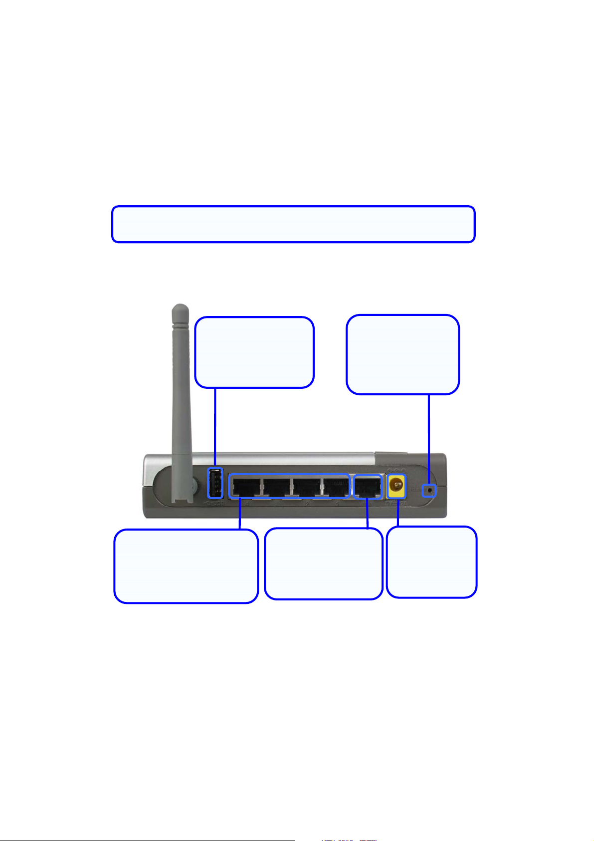
Connections
g
All Ethernet Ports (WAN and LAN) are auto MDI/MDIX, meaningyou can
use either a strai
ht-through or a crossover Ethernet cable.
USB 1.1 Connection
Use this port to
connect your USB
printer.
Auto MDI/MDIX LAN Ports
Connect the Ethernet
cable from computers on
your LAN to these ports.
Factory Reset Button
Pressing this button
will restore the router
to its factory default
WAN Port
Connect the Ethernet
cable from your ADSL
modem to this port.
settings.
Power Adapter
Connect your
5V 2.5A power
adapter here.
2
Page 7
LEDs
p
y
Power LED
A solid light
indicates a valid
connection to
the power
supply.
Status LED
A blinking LED
indicates the
DI-524UP is
functioning
properly.
WAN LED
An active LED
indicates a link
has been
established. A
blinking LED
indicates
activity on the
WAN port.
WLAN LED
An active LED indicates
a link has been
established. A blinking
LED indicates activity
on the WLAN
ort.
USB LED
An active LED indicates
a link has been
established. A blinking
LED indicates activity
on the USB port.
LAN LEDs
An active LED indicates
a link has been
established. A blinking
LED indicates activit
the LAN port.
on
3
Page 8

Features
• Fully compatible with the 802.11g standard to provide a wireless data rate of up
to 54Mbps
• Backwards compatible with the 802.11b standard to provide a wireless data rate
of up to 11 Mbps
• WPA authorizes and identifies users based on a secret key that changes
automatically at a regular interval, for example, TKIP (Temporal Key Integrity
Protocol), in conjunction with a RADIUS server, changes the temporal key every
10,000 packets, ensuring greater security
• Pre Shared Key mode means that the home user, without a RADIUS server, will
obtain a new security key every time the he or she connects to the network,
vastly improving the safety of communications on the network
• New WPA2 enhanced wireless security authenticates using 802.1X and a
Pre-Shared key, and encrypts the data with the AES encryption standard. Wi-Fi
certified, WPA2 is also compatible with WPA and can be used for a large
network or for the SOHO environment
• 802.1x Authentication in conjunction with the RADIUS server verifies the identity
of would be clients
• Utilizes OFDM technology (Orthogonal Frequency Division Multiplexing)
• User-friendly configuration and diagnostic utilities
• Operates in the 2.4GHz frequency range
• Connects multiple computers to a Broadband (Cable or DSL) modem to share
the Internet connection
• Advanced Firewall features
• Supports NAT with VPN pass-through, providing added security
• MAC Filtering
4
Page 9

• IP Filtering
• URL Filtering
• Domain Blocking
• Scheduling
• DHCP server supported enables all networked computers to automatically
receive IP addresses
• Web-based interface for Managing and Configuring
• Access Control to manage users on the network
• Supports special applications that require multiple connections
• Equipped with 4 10/100Mbps Ethernet ports, 1 WAN port, Auto MDI/MDIX
• Equipped with one USB 1.1 port at the rear of the router used to connect with a
USB printer
• VPN Pass-Through
• DMZ and DDNS functions
• Stateful Packet Inspection for protection against unwanted packets
• Quality of Service (QoS) for prioritizing ports and IP addresses
• Multiple users and administrators with configurable privileges for each
• Intrusion detection for ICMP, SYN, UDP flood, Land, IP spoof, Ping of Death,
Port Scan, Smurf, Steal Fin, Syn with data, Tear Drop, and UDP bomb attacks
• Statistics for all main functions on the router
5
Page 10

Wireless Basics
D-Link wireless products are based on industry standards to provide easy-to-use and
compatible high-speed wireless connectivity within your home, business or public
access wireless networks. D-Link wireless products will allow you access to the data
you want, when and where you want it. You will be able to enjoy the freedom that
wireless networking brings.
A WLAN is a cellular computer network that transmits and receives data with radio signals
instead of wires. WLANs are used increasingly in both home and office environments, and
public areas such as airports, coffee shops and universities. Innovative ways to utilize
WLAN technology are helping people to work and communicate more efficiently.
Increased mobility and the absence of cabling and other fixed infrastructure have proven to
be beneficial for many users.
Wireless users can use the same applications they use on a wired network. Wireless
adapter cards used on laptop and desktop systems support the same protocols as
Ethernet adapter cards.
People use wireless LAN technology for many different purposes:
Mobility -Productivity increases when people have access to data in any location
within the operating range of the WLAN. Management decisions based on real-time
information can significantly improve worker efficiency.
Low Implementation Costs WLANs are easy to set up, manage, change and
relocate. Networks that frequently change can benefit from WLANs ease of
implementation. WLANs can operate in locations where installation of wiring may be
impractical.
Installation and Network Expansion - Installing a WLAN system can be fast and
easy and can eliminate the need to pull cable through walls and ceilings. Wireless
technology allows the network to go where wires cannot go - even outside the home or
office.
Scalability WLANs can be configured in a variety of topologies to meet the needs
of specific applications and installations. Configurations are easily changed and range
from peer-to-peer networks suitable for a small number of users to larger infrastructure
networks to accommodate hundreds or thousands of users, depending on the number of
wireless devices deployed.
Inexpensive Solution - Wireless network devices are as competitively priced as
conventional Ethernet network devices.
6
Page 11

Standards-Based Technology
The DI-524UP Wireless Router utilizes the new 802.11g standard.
The IEEE 802.11g standard is an extension of the 802.11b standard. It increases the
data rate up to 54 Mbps within the 2.4GHz band, utilizing OFDM technology.
This means that in most environments, within the specified range of this device, you will
be able to transfer large files quickly or even watch a movie in MPEG format over your
network without noticeable delays. This technology works by transmitting high speed
digital data over a radio wave utilizing OFDM (Orthogonal Frequency Division
Multiplexing) technology. OFDM works by splitting the radio signal into multiple smaller
sub-signals that are then transmitted simultaneously at different frequencies to the
receiver. OFDM reduces the amount of crosstalk (interference) in signal transmissions.
The DI-524UP is backwards compatible with 802.11 b devices. This means that if you
have an existing 802.11 b network, the devices in that network will be compatible with
802.11g devices at speeds of up to 11 Mbps in the 2.4GHz range.
Installation Considerations
The D-Link DI-524UP lets you access your network, using a wireless connection, from
virtually anywhere within its operating range. Keep in mind, however, that the number,
thickness and location of walls, ceilings, or other objects that the wireless signals must
pass through, may limit the range. Typical ranges vary depending on the types of
materials and background RF (radio frequency) noise in your home or business. The
key to maximizing wireless range is to follow these basic guidelines:
1. Keep the number of walls and ceilings between the DI-524UP and other
network devices to a minimum - each wall or ceiling can reduce your D-Link
wireless product¡ƒs r angefr o m-90 feet (1-30 meters.) Position your devices so
that the number of walls or ceilings is minimized.
2. Be aware of the direct line between network devices. A wall that is 1.5 feet thick
(.5 meters), at a 45-degree angle appears to be almost 3 feet (1 meter) thick. At a
2-degree angle it looks over 42 feet (14 meters) thick! Position devices so that
the signal will travel straight through a wall or ceiling (instead of at an angle) for
better reception.
3. Building Materials can impede the wireless signal - a solid metal door or
aluminum studs may have a negative effect on range. Try to position wireless
devices and computers with wireless adapters so that the signal passes
through drywall or open doorways and not other materials.
4. Keep your product away (at least 3-6 feet or 1-2 meters) from electrical
devices or appliances that generate extreme RF noise.
7
Page 12

Getting Started
Setting up a Wireless Infrastructure Network
Please remember that D-Link AirPlus G wireless devices are pre-configured to connect
together, right out of the box, with their default settings. For a typical wireless setup at
home (as shown above), please do the following:
1. You will need broadband Internet access (a Cable or DSL-subscriber line
into your home or office)
8
Page 13

2. Consult with your Cable or DSL provider for proper installation of the
modem
3. Connect the Cable or DSL modem to the DI-524UP Wireless Router (see
the printed Quick Installation Guide included with your router.)
4. If you are connecting a desktop computer to your network, install the D-Link
AirPlus G DWL-G520 wireless PCI adapter into an available PCI slot on
your desktop computer. You may also install the DWL-G520. (See the
printed Quick Installation Guide included with the network adapter.)
5. Install the D-Link DWL-G650 wireless Cardbus adapter into a laptop
computer. (See the printed Quick Installation Guide included with the
DWL-G650.)
6. Install the D-Link DFE-530TX+ adapter into a desktop computer. The four
Ethernet LAN ports of the DI-524UP are Auto MDI/MDIX and will work with
both Straight-Through and Cross-Over cable. (See the printed Quick
Installation Guide included with the DFE-530TX+.)
Connect your printer to the printer port on the DI-524UP. Please refer to the quick
installation guide for loading the print server software.
9
Page 14
Using the Configuration Wizard
yp
s
pp
k
g
p
g
y
e
e
e
g
g
g
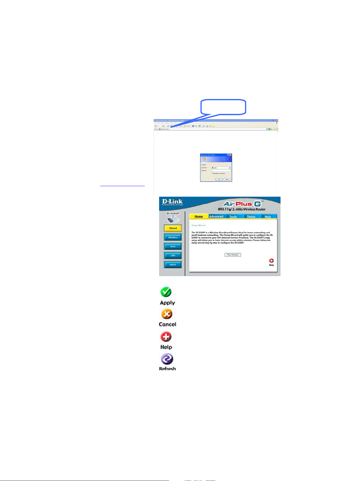
Whenever you want to configure
your network or the DI-524UP, you
can access the Configuration Menu
by opening the web-browser and
typing in the IP Address of the
DI-524UP. The DI-524UP default IP
Address is shown to the right:
• Open the web browser
• Type in the IP Address of the
Router (http://192.168.0.1
• T
e ¡§ad min¡ ¤i nthe U
Name field
)
• Leave the Password blank
• Click OK
The Home > Wizard window will
ear. Please refer to the Quic
a
Installation Guide for more information re
Wizard.
ardingthe Setu
192.168.0.1
These buttons appear on most of the
uration windows in this
confi
section. Please click on the
appropriate button at the bottom of
each window after
configuration change.
Note: if you have changed th
default IP Address assigned to th
DI-524UP, make sure to enter th
correct IP Address.
ou have made a
Clickingthis button will save configured
settings to the router.
Clickin
made to the current page.
Clickin
helpful information about the current
window.
Clickin
of the current window.
10
Cancel will clear changes
Helpwillprovide the user with
refresh will refresh the statistics
Page 15
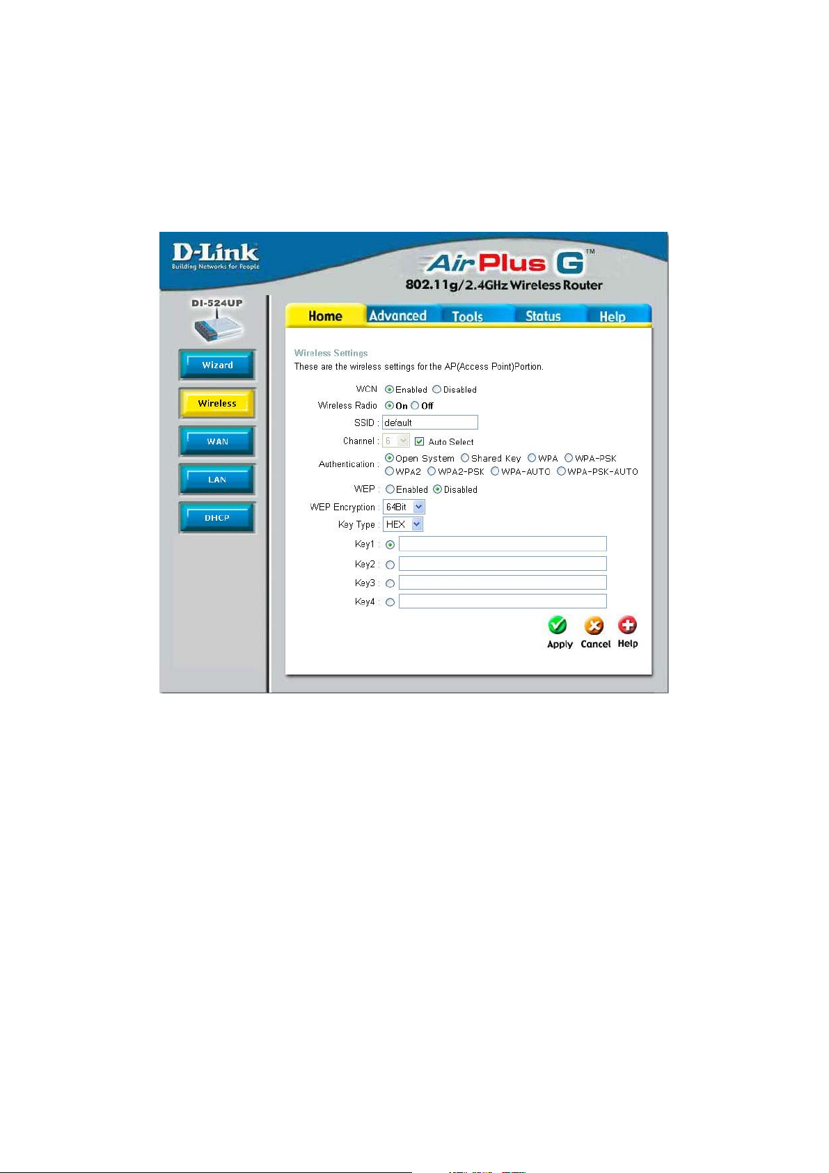
Home > Wireless
WCN WCN or Windows Connect Now Technology is used to
automatically configure the wireless settings for this device. The
WCN must be previously configured on computer running a
Windows XP operating system, which has Service Pack 2
installed. Once the configuration has been completed by
running the Wireless Network Setup Wizard, it must be saved
to a USB enabled memory device and then uploaded
automatically to the router and any other device to be put on
this wireless network, using this method. No configuration will
be necessary except for ensuring that this WCN radio button is
enabled before connecting the memory drive to the router. For
a concise explanation on configuring the WCN on Windows XP,
see the Appendix at the back of this manual. (Note: For the
11
Page 16

client implementation of this function, please see the user
manual for the associated client PC)
Wireless Radio Click the appropriate radio button to enable or disable the
Wireless Access part of this device.
SSID Service Set Identifier (SSID) is the name designated for a spe-
cific wireless local area network (WLAN). The SSID¡ƒs f act or y
default setting is DI-524UP. The SSID can be easily changed to
connect to an existing wireless network or to establish a new
wireless network. This field will be automatically configured for
users who have uploaded a WCN configuration.
Channel What channels are available for use by the access point
depends on the local regulatory environment. Remember that
all devices communicating with the device must use the same
channel (and use the same SSID). Use the drop-down menu to
select the channel used for your 802.11b wireless LAN.
Authentication This router employs three basic types of Authentication for
access to the router¡ƒs wir eless net w or k, Op e n S y st e m/Shared
Key 802.1X (RADIUS) and PSK (Pre-Shared Key), which can
be selected by clicking the corresponding radio button. Each
selection will alter the window to accommodate the entry of the
selected Authentication. See the explanation below for more
information.
Open System/Shared Key
The Open System/Shared Key choice for Authentication will produce the same window
for the user¡ƒs confi gur ati onThe Open System choice is for general use and utilizes the
basic WEP encryption. The Shared Key choice is used between cooperating devices
that share a common encryption key. WEP (Wireless Encryption Protocol or W ired
Equivalent Privacy) encryption can be enabled for security and privacy. WEP encrypts
the data portion of each frame transmitted from the wireless adapter using one of the
predefined keys. Decryption of the data contained in each packet can only be done if
the both the receiver and transmitter have the correct shared key.
12
Page 17
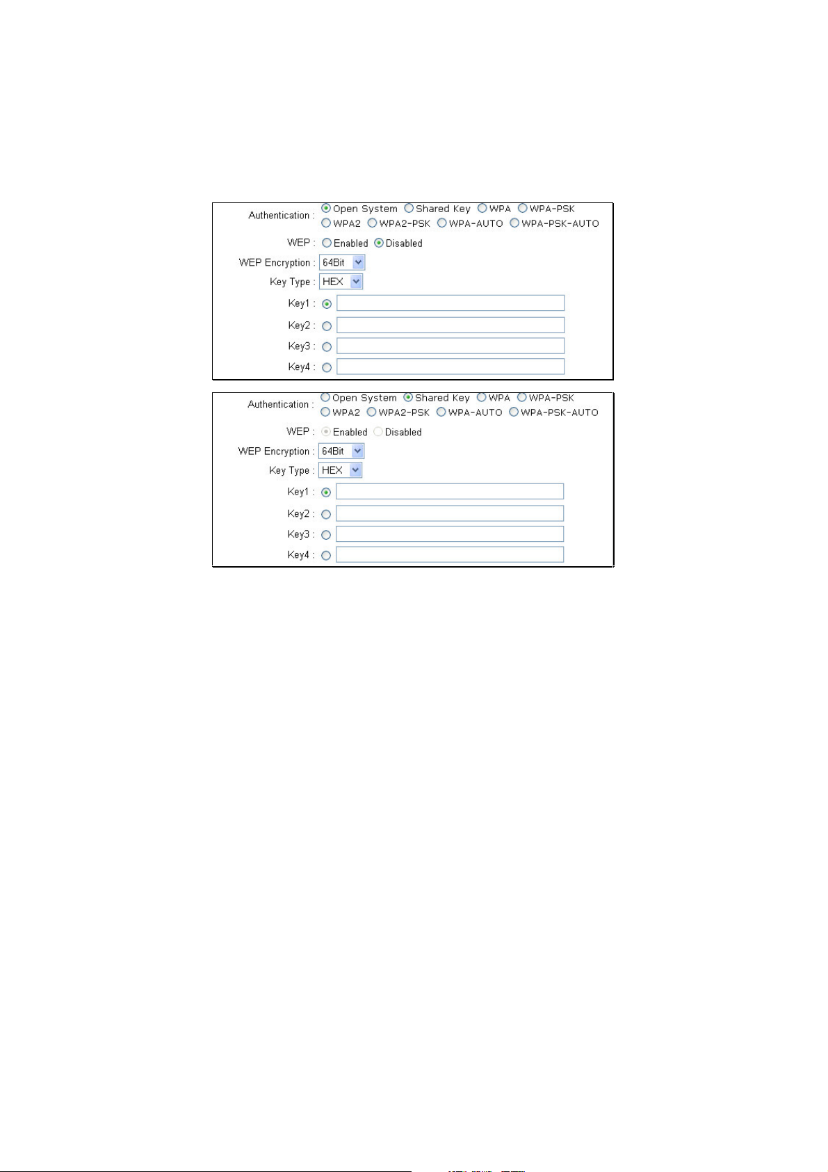
WEP Click the Enabled radio button to employ WEP encryption on the router.
WEP Encryption Use the drop-down menu to select the type of WEP encryption.
Select 64 Bit to enabled 64 bit Hexadecimal encryption, 128 Bit to enable 128 bit
Hexadecimal encryption. For 64-bit encryption, the (ASCII) characters are converted
automatically and listed as 10-digit hexadecimal keys. 64-bit encryption allows you to
select one of four active keys. For 128-bit encryption, the characters are converted and
listed as a 26 digit hexadecimal key. 128-bit encryption allows you to select one of four
active keys. 128-bit keys are to be from 5-13 inputted characters in length and 256-bit
keys must be from 10-26 inputted characters in length. Failing to have the same key on
the server and its clients will result in the clients not receiving any information from the
router or its connected devices.
Key Type Use the pull-down menu to select the type of Key to be used for encryption.
The user may choose HEX (Hexidecimal) or ASCII (American Standard Code for
Information Interchange). Both will require the user to enter a key in the following field.
Key The user may enter up to four keys to be used for encryption. Only the key
selected using the corresponding radio button will be used for encryption.
Click Apply to set the information in the router¡ƒs memor y (Note: For the client
implementation of this function, please see the user manual for the associated client
13
Page 18
PC)
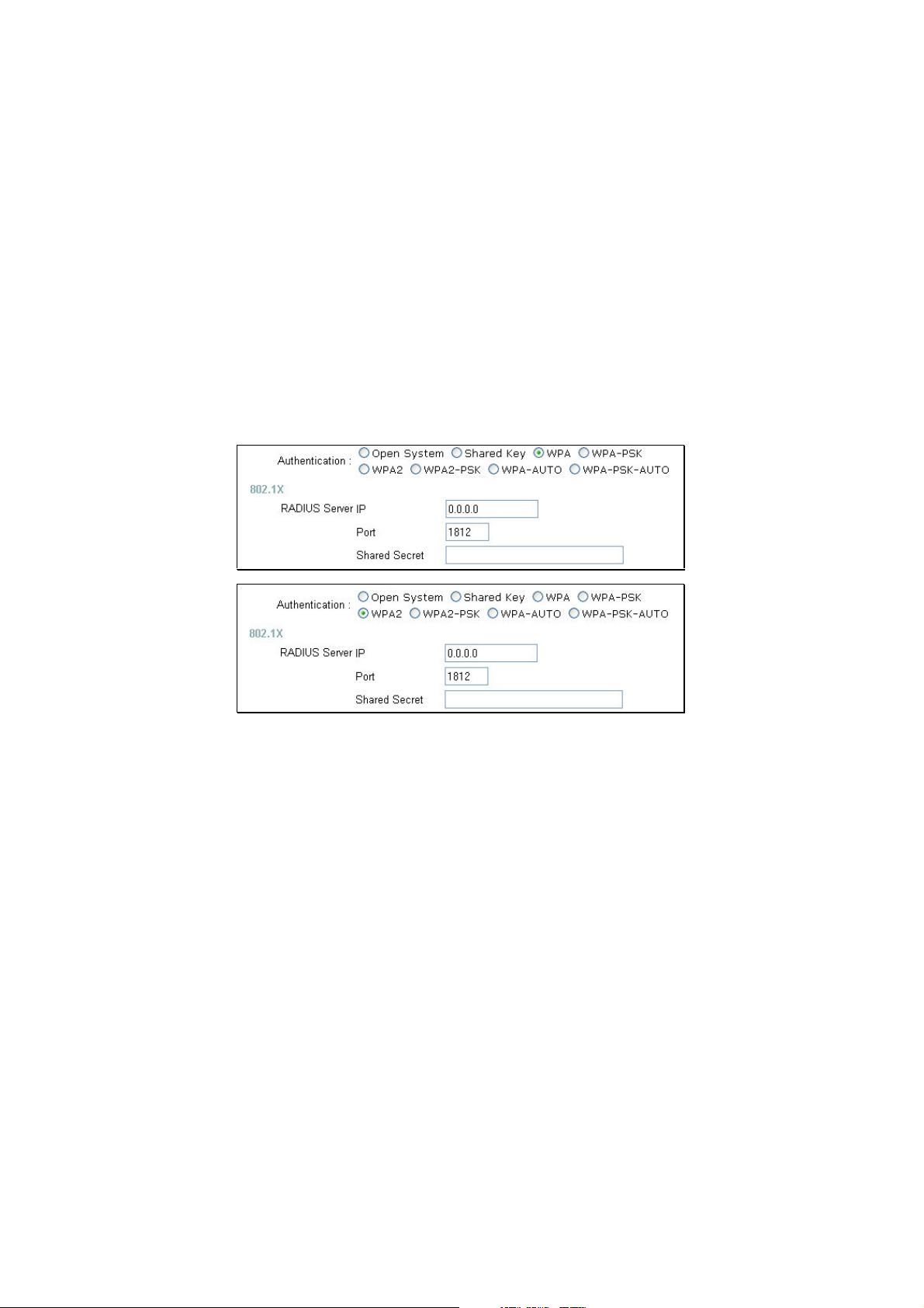
WPA/WPA2
WPA or Wireless Protection Access is a new an improved standard of wireless security.
WPA offers encryption keys of up to 256-bits that automatically change frequently. On
this router, the W PA utilizes the RADIUS protocol, which utilizes a server to authorize
the user by matching a Shared Secret password listed in its RADIUS database. There
are two choices for the user to choose from. WPA and WPA2, both use the Advanced
Encryption Standard (AES). In order to use this function, a RADIUS server must be
established on a computer on the LAN. This RADIUS server must be configured to have
thesamekeyastheusersontheLANaccessingit.
RADIUS Server IP Enter the IP address of the remote RADIUS server through which
you will be authenticated.
Port Enter the virtual port number to which to connect through the RADIUS server.
Common port numbers for RADIUS are 1812 and 1813.
Shared Secret Enter the password that will be used to authenticate you on the
wireless network. This password must be the same on the RADIUS server in order for
youtobeauthorized.(Note: For the client implementation of this function, please see
the user manual for the associated client PC.)
WPA-PSK/WPA2-PSK
WPA-PSK (Pre-Shared Key) uses the same encryption as the WPA but is implemented
differently. All devices on the wireless network share the same key (Passphrase) to
activate the WPA security. There are two choices for the user to choose from.
WPA-PSK and WP A2-PSK, which both use the Advanced Encryption Standard (AES).
To utilize, select one of the previous choices, enter the Passphrase, confirm it in the
14
Page 19
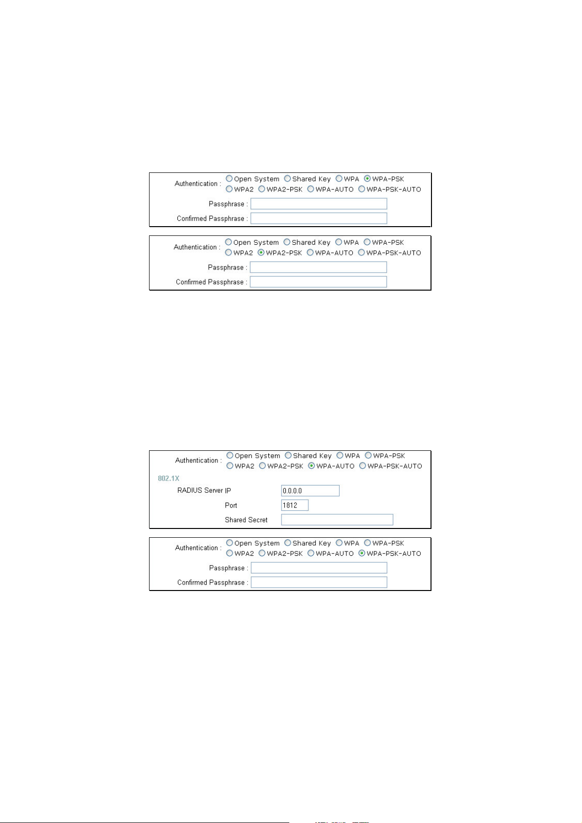
second field and click Apply. (Note: For the client implementation of this function,
please see the user manual for the associated client PC.)
WPA-AUTO/WPA-PSK-AUTO
In addition to standard Wireless Protection Access and WPA-PSK (Pre-Shared Key)
functions, the DI-524UP allows users an automatic option for both WPA and WPA-PSK.
In order to use the WPA-Auto function, a RADIUS server must be established on a
computer on the LAN. This RADIUS server must be configured to have the same key as
theusersontheLANaccessingit
To utilize the WPA-PSK-Auto function, select one of the previous choices, enter the
Passphrase, confirm it in the second field, and then click Apply.
(Note: For the client implementation of this function, please see the user manual for the
associated client PC.)
15
Page 20
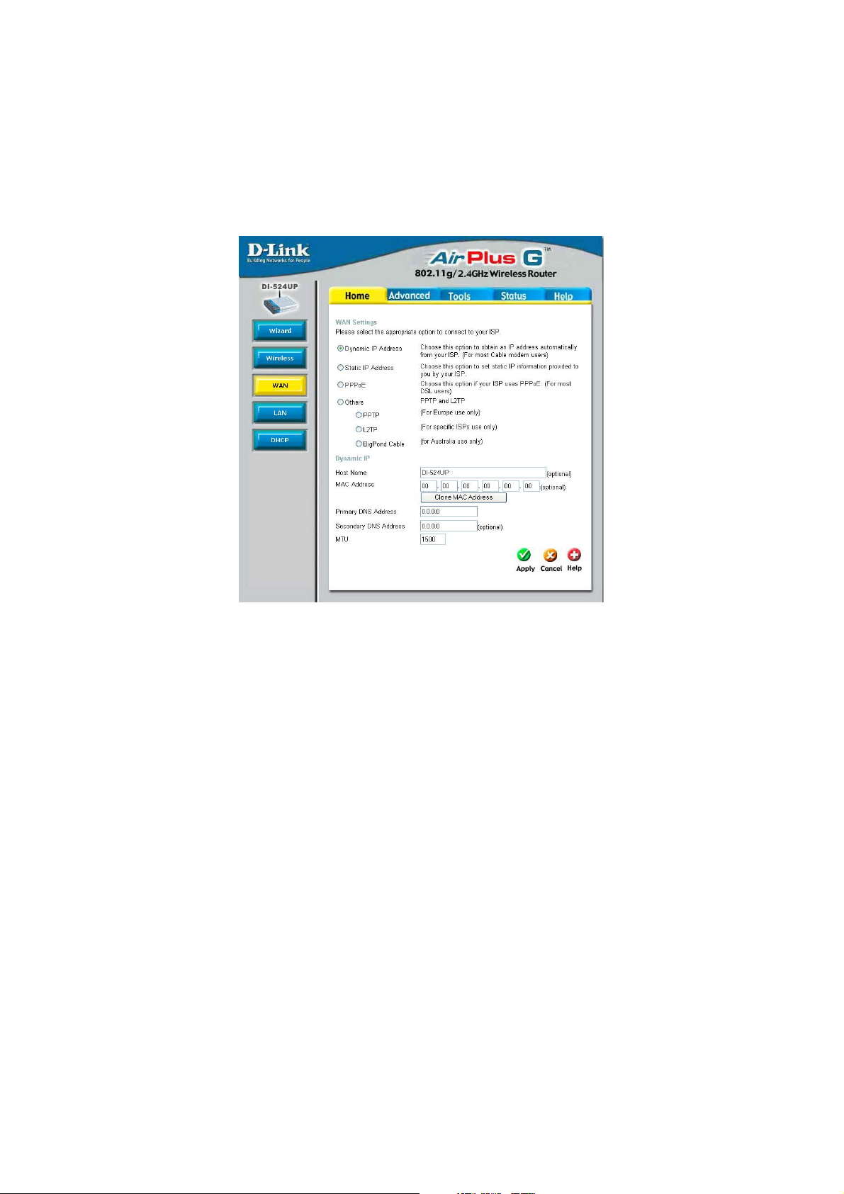
Home > WAN
y
y
Dynamic IP Address Choose Dynamic IP Address to obtain IP address information
automatically from your ISP. This option should be selected if
your ISP has not supplied you with an IP address. This option is
commonly used for Cable modem services.
Host Name The Host Name is optional but may be required by some ISPs.
The default host name is the device name of the Router and
may be changed.
MAC Address The default MAC Address is set to the WAN¡ƒs physicalinterface
MAC address on the Broadband Router. It is not recommended
that you change the default MAC address unless required by
your ISP.
Clone MAC Address The default MAC address is set to the WAN¡ƒs physicalinteface
MAC address on the Broadband Router. You can use the Clone
MAC Address button to copy the MAC address of the Ethernet
Card installed by your ISP and replace the WAN MAC address
with the MAC address of the router. It is not recommended that
you change the default MAC address unless required by your
Primar
DNS Address
/Secondar
ISP.
16
Page 21
Enter a DNS Address if you wish not to use the address
provided by your ISP.
MTU Enter an MTU value only if required by your ISP. Otherwise,
leave it at the default setting.
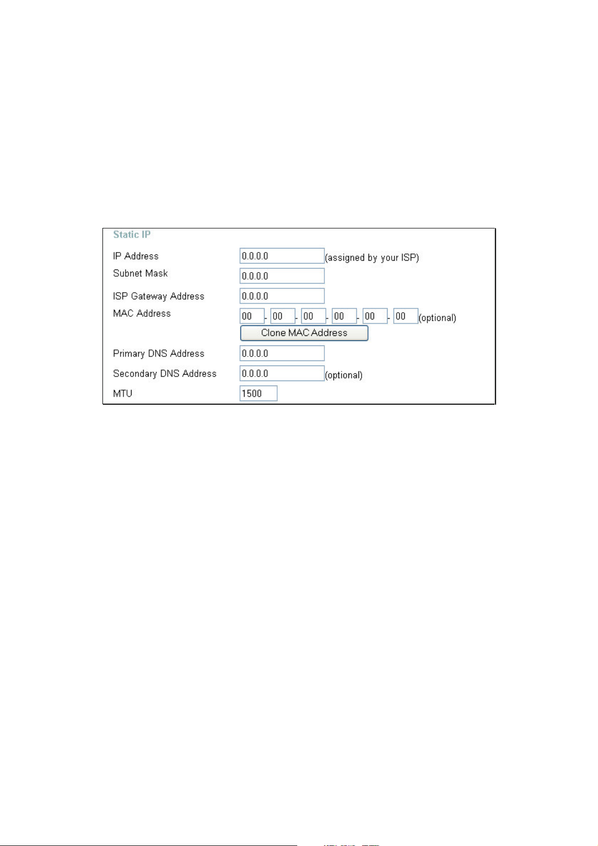
Home>WAN>StaticIPAddress
Static IP Address Choose Static IP Address if all WAN IP information is provided
to you by your ISP. You will need to enter in the IP address,
subnet mask, gateway address, and DNS address(es) provided
to you by your ISP. Each IP address entered in the fields must
be in the appropriate IP form, which are four octets separated
by a dot (x.x.x.x). The Router will not accept the IP address if it
is not in this format.
IP Address Input the public IP Address provided by your ISP.
Subnet Mask Input your Subnet mask. (All devices in the network must have
the same subnet mask.)
ISP
Gateway Address Input the public IP address of the ISP to which you are
connecting.
MAC Address The default MAC Address is set to the WAN¡ƒs physicalinterface
MAC address on the Broadband Router. It is not recommended
that you change the default MAC address unless required by
your ISP.
Primary
17
Page 22
DNS Address Input the primary DNS (Domain Name Server) IP address
y
p
p
provided by your ISP
Secondary DNS
Address This is an optional DNS Address entry to be used if the primary
DNS fails.
MTU Enter an MTU value only if required by your ISP. Otherwise,
leave it at the default setting.
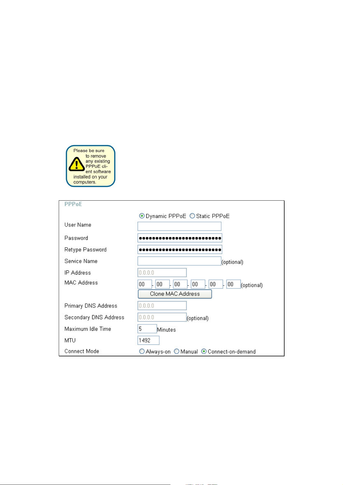
Home > WAN > PPPoE
Choose PPPoE (Point to Point Protocol over Ethernet) if
ISP uses a PPPoE connection. Your ISP will
with a username and
assword. This option is typicallyused
rovideyou
our
for DSL services. Select Dynamic PPPoE to obtain an IP
address automatically for your PPPoE connection. Select
Static PPPoE to use a static IP address for your PPPoE
connection.
PPPoE Choose this option if your ISP uses PPPoE. (Most DSL users
will select this option.)
18
Page 23

Dynamic PPPoE Choose this option to receive an IP Address
automatically from your ISP.
Static PPPoE Choose this option to you have an assigned
(static) IP Address.
Password Enter The PPPoE user name provided to you by your ISP.
Retype Password Retype the password entered in the previous field.
Service Name Enter the Service Name provided by your ISP (optional).
IP Address This option is only available for Static PPPoE. Enter the static
IP address for the PPPoE connection.
MAC Address The default MAC Address is set to the WAN¡ƒs physicalinterface
MAC address on the Broadband Router. It is not recommended
that you change the default MAC address unless required by
your ISP.
Clone MAC Address The default MAC address is set to the WAN¡ƒs physicalinterface
MAC address on the Broadband Router. You can use the
Clone MAC Address button to copy the MAC address of the
Ethernet Card installed by your ISP and replace the WAN MAC
address with the MAC address of the router. It is not
recommended that you change the default MAC address unless
required by your ISP.
Primary
DNS Address Input the primary DNS (Domain Name Server) IP address
provided by your ISP
Secondary
DNS Address This is an optional DNS Address entry to be used if the primary
DNS fails.
Maximum Idle Time The amount of time of inactivity before the device will
disconnect time your PPPoE session. Enter a Maximum Idle
Time (in minutes) to define a maximum period of time for which
the Internet connection is maintained during inactivity. If the
connection is inactive for longer than the defined Maximum Idle
Time, then the connect ion will be dropped. Either set the value
for idle time to zero or enable Auto-reconnect to disable this
feature.
MTU Enter an MTU value only if required by your ISP. Otherwise,
leave it at the default setting.
19
Page 24
Connect Mode Allows the user to choose a method of connecting to the ISP.
g
y
P
y
y
y
yby
Always-On will keep the router connected through Idle times.
Manual will require the user to connect manually using the
router anytime a connection to the ISP has timed out.
Connect-on-demand will instruct the router to connect to the
ISP anytime information is sent from the connected computer
on the LAN.
Click Apply to set any changes made to the memory of the router.
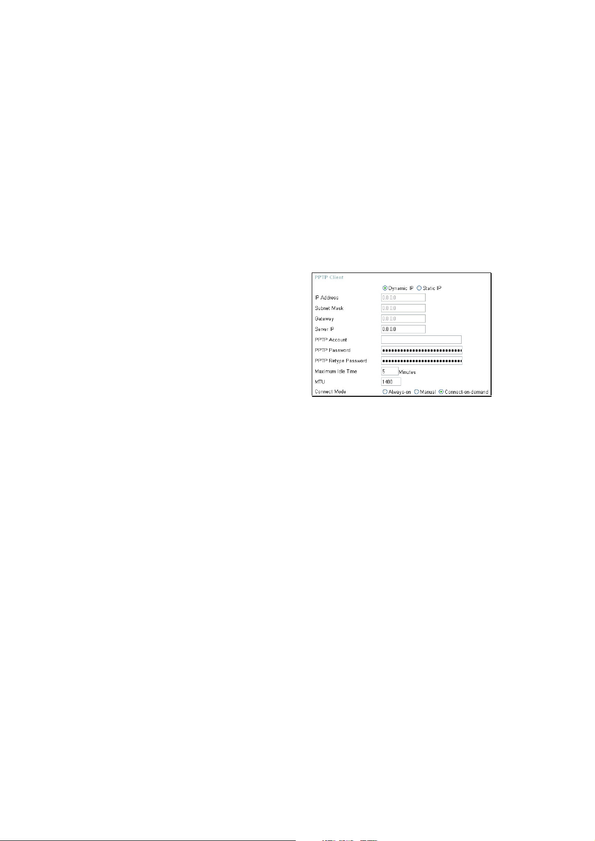
Home > WAN > Others > PPTP
PPTP or Point-to-Point Protocol is a safe
method of sendin
VPN¡ƒs secur el
information between
usingencrypti on ov er PP
You, as the client, need to enter the correct
information that the server has in order to
create that secure tunnel. Using Dynamic IP,
the router will set
for
ou, such as the IP Address, Subnet
Mask and Gatewa
information must be set manuall
our basic IPparameters
.ForStaticIP,this
the
user. All information in this window should be
provided by your ISP.
PPTP Choose between Dynamic and Static IP.
IP Address Enter the IP address of the router for a static IP entry. Dynamic
IP requires no input here.
Subnet Mask Enter the Subnet Mask address of the router for a static IP
entry. Dynamic IP requires no input here.
Gateway Enter the gateway address here. This is the IP address of the
ISP server.
Server IP Enter the IP address of the PPTP¡ƒs ser ver co mputer. Thisis
how the user will become authenticated to use PPTP.
PPTP Account Enter the name of the PPTP account as provided to you by
your ISP.
PPTP Password Enter the PPTP password as provided to you by your ISP.
PPTP Retype Retype the password entered in the PPTP Password field.
Password
20
Page 25
Maximum Idle Time A value of 0 means that the PPP connection will remain
yreq
g
p
g
g
g
p
py
g
connected. If your network account is billed according to the
amount of time the Router is actually connected to the Internet,
enter an appropriate Idle Time value (in seconds). This will
disconnect the Router after the WAN connection has been idle
for the amount of time specified. The default value = 5.
MTU Enter an MTU value only if required by your ISP. Otherwise,
leave it at the default setting.
Connect Mode This function, with Connect-on-demand selected, will allow the
router to connect any workstation on your LAN to the Internet
upon request. If this function is set at Always-on, no request
from the workstation will be needed to connect to the Internet. If
Manual is selected, it will be necessary for the workstation on
the LAN to manually connect to the Internet through this router.
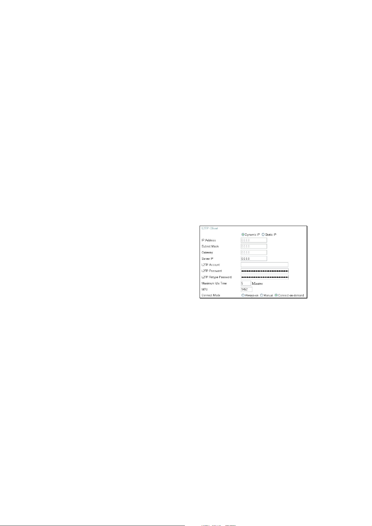
Home > WAN > Others > L2TP
Some ISPs ma
using the Layer 2Protocol Tunnelin
method. L2PT is a VPN
uiretheusertouplink
(L2PT)
rotocol that will
ensure a direct connection to the server
usin
an authenticationprocess that
uarantees the data originated from the
claimed sender and was not dama
ed or
altered in transit. Once connected to the VPN
tunnel, it seems to the user that the client
com
uter is directlyconnected to the internal
network. To set u
enter the followin
our L2PT connection,
data that wasprovided to
you by your ISP.
L2PT Choose between Dynamic and Static IP. Using Dynamic IP,
the router will set your basic IP parameters, such as the IP
Address, Subnet Mask and Gateway. For Static IP, this
information must be set manually by the user.
IP Address The IP address that will be assigned to your router for this
connection, as stated by your ISP. Dynamic IP requires no
input here.
Subnet Mask The IP address of the corresponding Subnet Mask, as stated to
you by your ISP. Dynamic IP requires no input here.
Gateway The IP address of the gateway device, as stated to you by your
ISP. Dynamic IP requires no input here.
21
Page 26

Server IP The IP address of your ISP¡ƒs ser ver co mputer, asstatedtoyou
by your ISP.
L2PT Account The account name of the L2PT account that has been assigned
to you by your ISP.
L2PT Password The password of the L2PT account that was supplied to you by
your ISP.
L2PT Retype Password Retype the password that was entered in the L2PT field.
Ensure that these two passwords are identical or an error will
occur.
Maximum Idle Time A value of 0 means the PPP connection will remain connected.
If your network account is billed according to the amount of time
the Router is actually connected to the Internet, enter an
appropriate Idle Time value (in seconds). This will disconnect
the Router after the WAN connection has been idle for the
amount of time specified. The default value = 5.
MTU Enter an MTU value only if required by your ISP. Otherwise,
leave it at the default setting.
Connect Mode If Connect-on-demand is selected, will allow the router to
connect any workstation on your LAN to the Internet upon
request. If Always-on, no request from the workstation will be
needed to connect to the Internet. If M anual is selected, the
workstation on the LAN must manually connect to the Internet
through this router.
Home > WAN > Others > BigPond Cable
This selection is for users having Big Pond Cable as their ISP. Enter the following
information, as provided to you by your ISP.
22
Page 27

User Name Enter the user name as provided to you by your ISP.
Password Enter The PPPoE user name provided to you by your ISP.
Retype Password Retype the password entered in the previous field.
Auth Server Enter the name of the Authentication Server as provided to you
by your ISP. This is the computer that will accept your user
name and password to be authenticated on the network.
Auto Reconnect Checking the Enabled radio button will allow the router to
reconnect to the network automatically if it becomes
disconnected.
MAC Address The default MAC Address is set to the WAN¡ƒs physicalinterface
MAC address on the Broadband Router. It is not recommended
that you change the default MAC address unless required by
your ISP.
Clone MAC Address The default MAC address is set to the WAN¡ƒs physicalinterface
MAC address on the Broadband Router. You can use the
Clone MAC Address button to copy the MAC address of the
Ethernet Card installed by your ISP and replace the WAN MAC
address with the MAC address of the router. It is not
recommended that you change the default MAC address unless
required by your ISP.
MTU Enter an MTU value only if required by your ISP. Otherwise,
leave it at the default setting.
23
Page 28

Home > LAN
y
g
y
g
y
p
LAN is short for Local
Area Network. This is
considered
internal network.
These are the IP
settin
s of the LAN
interface for the
DI-524UP and ma
referred to as Private
settin
s. You ma
changetheLANIP
address if needed.
The LAN IP address is
rivate toyour internal
network and cannot be
seen on the Internet.
IP Address The IP address of the LAN interface. The default IP address is
Subnet Mask The subnet mask of the LAN interface. The default subnet
our
be
192.168.0.1.
mask is 255.255.255.0.
Local Domain Name This entry is for the local Domain set on your network, if you
have given it a name previously. This field is for your personal
use and unnecessary for proper configuration of this window.
DNS Relay The Router can be configured to relay DNS from your ISP or
another available service to workstations on your LAN. When
using DNS relay, the Router will accept DNS requests from
hosts on the LAN and forward them to the ISP (or alternative)
DNS servers. DNS relay can use auto discovery or the DNS IP
address can be manually entered by the user. Alternatively, you
may also disable the DNS relay and configure hosts on your
LAN to use DNS servers directly. Most users who are using the
Router for DHCP service on the LAN and are using DNS
servers on the ISP¡ƒs network, will l eave DNS r elay enabled
(either auto discovery or user configured).
24
Page 29

Advanced > Virtual Server
To view the following window, click on the Advanced tab at the top of the window and
then click the Virtual Server button to the left. The Virtual Server will allow remote
users access to various services outside of their LAN through a public IP address, such
as FTP (File Transfer Protocol) or HTTPS (Secure Web). After configuring the Router
for these features, the Router will redirect these external services to an appropriate
server on the users LAN. The Router has 13 pre-configured external services already
set, but the user may add alternate services using the window below. The Virtual
Servers listed in the following window are:
• FTP File Transfer Protocol, used to transfer large files over the Internet
• HTTP HyperText Transfer Protocol, the basic protocol of the World Wide Web
• HTTPS HyperText Transfer Protocol Secure, the basic protocol of the World
Wide Web with added security provided by the Secure Shell feature (SSH)
• DNS Domain Name Server, a server that translates website addresses into IP
25
Page 30

addresses
• SMTP Simple Mail Transfer Protocol, used to transmit e-mail messages
between parties
• POP3 Post Office Protocol version 3, used to retrieve e-mail from a mail
server
• Telnet A terminal emulation program used for remote configuration
• IPSec IP Security, used for a secure transfer of information over the network.
If one end of the transmission is using IPSec, so must the other end
• PPTP Point to Point Tunneling Protocol, used to transfer information securely
between VPNs (Virtual Private Routers)
• NetMeeting An application that allows teleconferences over the Internet
• DCS 1000 A D-Link internet camera used for security monitoring
• DCS 2000 A D-Link internet camera used for security monitoring
• DVC 1000 A D-Link VideoPhone used for video conferencing
These external services may be modified by clicking its corresponding edit icon, or they
may be deleted by clicking the corresponding delete icon. Though there are seven fields
available to configure the Virtual Server, in most cases, only the IP address of the
Virtual Server will be needed for implementation. To enable an already existing Virtual
Server, click its corresponding edit button, configure the appropriate fields listed below
and set the Status fields to Enabled by clicking the radio button. To configure other
virtual servers for the Router, configure the following fields and click Apply.
Virtual Server Click the radio button to enable or disable the selected Virtual
Server.
Name Enter the name of the Virtual Server. If you have chosen a
pre-configured Virtual Server from the list, its name will appear
in this field.
Private IP Enter the IP address of the Virtual Server.
Protocol Type The protocol type used for the Virtual Server. The user may
select TCP, UDP or Both, depending on the type of Virtual
Server implemented.
26
Page 31

Private Port Enter the port number of the Virtual Server¡ƒs co mputer. Existing
Virtual Servers listed already have their well-known port
number listed yet this may need to be changed in certain
circumstances.
Public Port Enter the port number of the device on the WAN side of the
network that will be accessing the Virtual Server currently being
configured. Commonly, this port number is identical to the
Private Port number. Existing Virtual Servers listed already
have their well-known port number listed yet this may need to
be changed in certain circumstances.
Schedule Configure the time schedule you wish these Virtual Servers to
be accessed. Clicking the Always radio button will allow access
to these servers at any time. The user may set a strict time
period by clicking the From radio button and configuring a time
period for access.
27
Page 32

The Applications
g
q
p
g
g
g
p
y
g
pp
p
y
gfig
y
pp
g
window is used to
confi
ure applications
that re
connections, such as
Internet Tele
video conferencin
Internet
followin
S
ecial Applications that
commonl
one connection. To
confi
a
corres
and then modif
fields listed below the
followin
clicking the Enabled
radio button. The user
ma
a
the fields listed and then
clicking the Enabled
radio button. New entries
will be listed at the
uire multiple
hony,
and
aming.The
window lists six
use more than
ure one of these
lications, click its
ondingedit icon
the
ure and then
add a new
lication bymodifyin
Advanced > Applications
Applications Click the appropriate corresponding radio button to enable or
disable the Applications feature.
Trigger Port Enter the port associated with the Name entered above. This is
the port that will ¡§tri gger¡ ¤ thi s applicationto accept mult ipl
connections.
Trigger Type Choose the protocol type of the Special Application from the
pull-down menu. The choices available to the user are TCP,
UDP or Both.
Public Port Enter the port number on the WAN side of the connection that
will access the Special Application. This field will accept a port,
multiple ports which are to be separated by a comma upon
entry, or a range of ports, which are to be separated by a dash.
Public Type This entry will trigger the public port on the WAN side of the
28
Page 33

connection for the specified application. The choices available
to the user are TCP, UDP or Both.
Advanced > Filters
Packet filtering is a basic security measure that should be used on any network that is
exposed to a security risk. A packet filter system examines data packets and scrutinizes
them in order to control network access. Filtering rules determine whether packets are
passed through the Router from either side of the gateway. The rules are created and
controlled by the network administrator and can be precisely defined. These rules are
used to block access to the LAN from outside the network and/or to deny access to the
WAN from within the network. The Router uses filtering rules to examine data packet
headers for specific information. Packets passing through the Router that do not meet
the criteria specified by the rule set are dropped.
29
Page 34

Effective implementation of packet filtering requires detailed knowledge of network
g
g
ysp
p
p
g
p
y
y
g
p
g
p
g
g
g
p
g
services and communication protocols. An overly complicated filtering scheme can
adversely affect the Router¡ƒs perf or mance,whil e an i nadequate setofrules may
needlessly compromise security.
This Router has two fields to configure for filtering which are IP Filters and MAC Filters.
Advanced > Filters > IP Filters
This window will aid
the use in confi
urin
filters for IP
addresses. This will
den
ecified LAN
IP addresses or
s
ecific
orts
associated with these
LAN IP address from
accessin
the
Internet. Well known
orts have alread
beenpreviouslyset
in the IP Filters List
and can be modified
clickin
b
corres
ondin
icon, and sim
addin
an IP address
to the confi
their
edit
le
uration.
To access this
window, click the
Advanced tab alon
the to
uration window
confi
of the
and then the Filters
tab to the left hand
side.
IP Filters Choose whether to enable or disable this configuration for IP
filtering.
IP Address An IP address or range of IP addresses that will be denied
access to the Internet.
Port A port or range of ports that will be denied access to the
Internet. If no port is entered, all ports in this IP range will be
30
Page 35

denied access to the Internet.
q
y
g
y
y
p
g
p
g
y
p
g
Protocol Type The protocol associated with this IP filter. The user may choose
between TCP, UDP or Both.
Schedule The user may configure time intervals that these IP filters will
become active. Clicking the Always radio button will not allow
access to these IP filters at any time. The user may set a strict
time period by clicking the From radio button and configuring a
time period to deny these IP addresses from accessing the
Internet.
All computers are
uelyidentified b
uni
Advanced > Filters > MAC Filters
their MAC (Media
Access Control)
address. The
followin
window will
allow users to den
computers access to
the Internet or onl
allow certain
com
uters access to
the Internet, based on
their MAC address.
To access this
window, click the
Advanced tab alon
the to
confi
uration window,
of the
then the Filters tab to
the left hand side and
finall
corres
click the
ondin
radio
button for MAC
Filters.
Disabled MAC Filters Click this radio button to disable MAC filtering on the
Router.
Only Allow Click this radio button if you wish to allow specific
computers access to the network, based on MAC
address.
Only Deny Click this radio button if you wish to deny specific
computers access to the network, based on MAC
31
Page 36

address.
Name A Name defined by the user to identify this MAC
address filter setting.
MAC Address Enter the MAC address to be filtered.
DHCP Client This field will display the DHCP client¡ƒs host na meand
MAC address here. You may clone this MAC address
by simply clicking the Clone button. The cloned entry
will be displayed in the MAC Filters List.
Advanced > Parental Control
Parental Control is used to deny access to certain websites and domains on the Internet.
This is beneficial for users who want to deny computers on the LAN entry to websites,
especially for parents who want to guard against questionable content for their
children¡ƒs co mput er s. The ad ministrator hast wochoicesinthis window,URLblocking
32
Page 37

(websites) and Domain Blocking. See the following for more information on Parental
control and its implementation.
Advanced > Parental Control > URL Blocking
URL or Uniform Resource Locator is a specially formatted text string that uniquely
defines an Internet website. This window will allow users to block computers on the LAN
from accessing certain URLs. This may be accomplished by simply entering the URL to
be blocked in the URL Keyword field. The user may also use this field to block certain
websites by entering a keyword into the URL Keyword field. So, if any website¡ƒs URL
contains this word, it will automatically be denied access to users on the LAN.
For example, if you wish to block users from accessing shopping websites, enter the
keyword ¡§shopping¡¤intothe URLKeywordf ield. Websi t e s h avi ng ¡ §shopping¡¤inth
URL (such as http://www.yahoo.com/shopping/stores.html or
http://www.msn/search/shopping-spree.html) will now be denied access from computers
on the LAN. This feature may be beneficial to parents wanting to stop their kids from
accessing certain websites or for companies who want their employees to stop surfing
the Internet on company time.
To configure this window for URL blocking, enter the website¡ƒs addr ess or a key wor d
into the URL Keyword field and click the radio button to enable URL Blocking and then
click Apply to save this configuration into the Router¡ƒs memor y. Co nfi gur ed U RL
blocking entries will be displayed in a list at the bottom of the window. To modify a URL
blocking entry in the list, click its corresponding edit icon. To delete a URL blocking entry
in the list, click its corresponding delete icon.
33
Page 38

Advanced > Parental Control > Domain Blocking
Domain blocking is a method of denying or allowing computers on the LAN access to
specific domains on the Internet. There are two available methods available to the user
to institute Domain blocking on the router. Under the Domain Blocking header in the
screen pictured above, the user has three choices, one of which is to disable Domain
blocking. The second choice is Allow users to access all domains except ¡ § Bl ocked
Domainsi . This option is for users who wish to block certain domains from being
accessed by local users on the LAN, but leave the rest open for use. To specify which
Domains you wish to exclude from use by computers on the LAN, enter the Domain¡ƒs
URL (ex. yahoo.com, google.com) into the Blocked Domains field and then click Apply.
The blocked entry will appear in the Blocked Domains List at the bottom of the screen.
To modify an entry in this list, click its corresponding edit icon. To delete an entry from
this list, click its corresponding delete icon.
For users wishing to allow computers on the LAN access to only specified domains,
choose option three under the Domain Blocking heading, Deny users to access all
domains except ¡ § Per mitt ed Do mains. To specify which domains you wish to include
for this option, enter the Domain¡ƒs URL ( ex. yahoo.co m, google.com)i ntothePermitted
Domains field and then click Apply. The permitted entry will appear in the Permitted
Domains List at the bottom of the window. To modify an entry in this list, click its
corresponding edit icon. To delete an entry from this list, click its corresponding delete
34
Page 39

icon.
NOTE: Choosing the Deny users to access all domains except ¡ § Per mitt ed
Domains¡ ¤option will block access to all other Internet traffic except the Domains
specified. Be careful not to misuse this option or users on the LAN will have difficulty
accessing network resources.
Advanced > Firewall
This Router comes equipped with a firewall. The Firewall configuration screen allows
the Router to enforce specific predefined policies intended to protect against certain
common types of attacks. To configure the Router¡ƒsfir ewall, cli ck t heAdvanced tab at
the top of the screen and then the Firewall tab to the left. To configure rules for the
firewall, modify the following fields and click Apply to set the rule in the Routers memory.
Newly configured firewall rules will be displayed in the Firewall Rules List at the bottom
35
Page 40

of the page. To modify an entry in this list, click its corresponding edit icon. To delete an
entry from this list, click its corresponding delete icon.
Firewall Click the corresponding radio button if you wish to enable or
disable the firewall function on the Router.
Name Enter a name that will define the firewall rule to be configured.
This entry is dependant on how the user wishes to classify this
rule.
Action Click whether to Allow or Deny traffic to pass through the
Router by checking the corresponding radio button. Users may
configure only specific traffic to pass through the router by
checking Allow or users may stop specific traffic from passing
through the Router by checking Deny.
Source Enter the IP address or range of IP addresses that you wish to
block or allow to pass through the router. The Source may be
identified on the LAN side, the WAN side or both by using the
pull-down menu for the Interface heading.
Dest Enter the IP address or range of IP addresses that you wish to
deny or allow access to the Internet. The Destination may be
identified on the LAN side, the WAN side or Both by using the
pull-down menu for the Interface heading. The type of protocol
may also be chosen by using the pull-down menu. The user
may choose between TCP, UDP, ICMP or (*) Any. The user
may also select a range of ports of the destination IP addresses
by entering the range under the Port Range heading.
Schedule Clicking Always will set the firewall permanently, unless
changed by the user. Alternately, the user may set up a time
schedule to implement the firewall, on a week-to-week basis by
clicking the From radio button and setting the appropriate times
to begin and end the firewall function.
36
Page 41

Advanced > DMZ
Firewalls may conflict with certain interactive applications such as video conferencing or
playing Internet video games. For these applications, a firewall bypass can be set up
using a DMZ IP address. The DMZ IP address is a ¡§visibl e¡ ¤ addr ess and does no
benefit from the full protection of the firewall function. Therefore it is advisable that other
security precautions be enabled to protect the other computers and devices on the LAN.
It may be wise to use isolate the device with the DMZ IP address from the rest of the
LAN.
For example, if you want to use video conferencing and still use a firewall, you can use
the DMZ IP address function. In this case, you must have a PC or server through which
video conferencing will take place. The IP address of this PC or server will then be the
DMZ IP address. You can designate the server¡ƒsI P addr ess ast he DMZ byt ypinginthe
IP address in the IP Address space provided and then enabling its status by clicking
the Enabled radio button and then click Apply.
For the system that uses the DMZ IP address, you may want to manually assign an IP
37
Page 42

address to it and adjust your DHCP server addresses so that the DMZ IP address is not
included in the DHCP server range. This way you avoid possible IP address problems if
you reboot the DMZ system. To configure the Router¡ƒs DMZ I P addr ess, cli ck t he
Advanced tab at the top of the window and then the DMZ tabtotheleft
.
Advanced > DDNS
The DI-524UP supports Dynamic Domain Name Service. Dynamic DNS allows a
dynamic public IP address to be associated with a static host name in any of the many
domains, allowing access to a specific host from various locations on the Internet. With
this function enabled, remote access to a host will be allowed by choosing a URL by
using the pull-down menu. Because many ISPs assign public IP addresses using DHCP,
it can be difficult to locate a specific host on the LAN using the standard DNS. For
example, if you are running a public web server or VPN server on your LAN, DDNS
ensures that the host can be located from the Internet if the public IP address changes.
38
Page 43

Note: DDNS requires that an account be setup with one of the supported DDNS servers
prior to engaging it on the router. This function will not work without an accepted
account with a DDNS server.
DDNS Click the Enabled button to enable the DDNS feature
on the router.
Server Address Choose the DDNS server address from the pull down
menu. Available servers include DynDns.org,
No-IP.com, hn.org and zoneedit.com.
Host name Enter the host name of the DDNS server.
Username Enter the username given to you by your DDNS server.
Password Enter the password given to you by your DDNS server.
Click Apply to set this information in the Router
.
39
Page 44

Advanced > QoS
QoS or Quality of Service is used to allot bandwidth and priority from the router. To allot
bandwidth per port on the router, click the appropriate QoS radio button and configure
the parameters. QoS may be configured per Physical Port, MAC address, I P address
or specified application. See the following explanation for more detailed information on
each type of QoS setting.
40
Page 45

Advanced > QoS > Physical Port
To enable QoS per port, first click the Physical Port radio button which will reveal the
preceeding window for the user to configure. Simply click the Enable check box of the
corresponding port to enable QoS. You may also set the bandwidth for that port by
using that corresponding pull-down menu. The user may choose a bandwidth between
128 Kbps to 32 Mbps. FULL denotes that the port will have the maximum transfer
speed allowed at any given time, up to 100Mbps. Click Apply to confirm your settings.
41
Page 46

Advanced > QoS > MAC
The user may also set QoS by specific MAC address. To enable QoS per MAC address,
first click the MAC radio button which will reveal the preceeding window for the user to
configure. Ensure that the Bandwidth configured does not exceed the incoming
bandwidth from the ISP or it will cause other devices on the LAN to slow down due to
decreased bandwidth. Check with your ISP for more information on the bandwidth
allotted to your account.
WAN Uplink Bandwidth Use the pull-down menu to set the WAN Uplink Bandwidth.
The user may choose a speed from 64kbps to Full (100Mbps).
Ensure that the Bandwidth does not exceed the incoming
42
Page 47

bandwidth from the ISP or it will cause other devices on the
LAN to slow down due to decreased bandwidth. Check with
your ISP for more information on the bandwidth allotted to your
account.
QoS Control by MAC Click the Enabled radio button to enable QoS priority by MAC
address. Information coming from this MAC address will have
the highest priority on the LAN. This means that information
originating from this device will be sent to other devices on the
LAN requesting it, first. Other devices will have a lower priority
in sending information through the router.
Source MAC Enter the source MAC address that will be set for high priority
QoS in the router.
DHCP Client The user may use the DHCP client to aid in choosing the MAC
address to be implemented for QoS. All devices connected to
the router will be listed in the pull-down menu. Simply choose
the correct device and click the Clone button, which will
produce that devices MAC address in the Source MAC field.
Bandwidth Use the pull-down menu to select the best bandwidth for the
QoS Setting on this router. The user may set a bandwidth
between 1Kbps to 32Mbps. Choosing Best Effort will set the
router to allow the first user to access the source MAC address
to have the total bandwidth needed for the file being transferred.
Choosing Full will denote that the router will allot 100Mbps of
bandwidth for the specified QoS implementation. Only one QoS
implementation can be set at Full.
Click Apply to set the QoS for MAC
.
43
Page 48

Advanced > QoS > IP
The user may also set QoS by specific IP address. To enable QoS per IP address, first
click the IP radio button which will reveal the preceeding window for the user to
configure. Ensure that the bandwidth does not exceed the incoming bandwidth from the
ISP or it will cause other devices on the LAN to slow down due to decreased bandwidth.
Check with your ISP for more information on the bandwidth allotted to your account.
44
Page 49

Upstream Bandwidth Use the pull-down menu to set the Upstream Bandwidth.The
user may choose a speed from 64kbps to Full (100Mbps).
Ensure that the bandwidth does not exceed the incoming
bandwidth from the ISP or it will cause other devices on the
LAN to slow down due to decreased bandwidth. Check with
your ISP for more information on the bandwidth allotted to your
account.
QoS Control by IP Click the enabled radio button to enable QoS priority by MAC
address. Information coming from this IP address will have the
highest priority on the LAN. This means that information
originating from this device will be sent to other devices on the
LAN requesting it, first. Other devices will have a lower priority
in sending information through the router.
Source IP Address Enter the source IP address or range of IP addresses that will
be set for high priority QoS in the router.
Reserved Bandwidth Use the pull-down menu to select the best bandwidth for the
QoS setting on this router. The user may set a Bandwidth
between 1Kbps to 32Mbps. Choosing Best Effort will set the
router to allow the first user to access the source IP address to
have the total bandwidth needed for the file being transferred.
Choosing Full will denote that the router will allot 100Mbps of
bandwidth for the specified QoS implementation. Only one QoS
implementation can be set at Full.
Click Apply to set the QoS for IP
.
45
Page 50

Advanced > QoS > Application
The user may also set QoS by specific protocol. To enable QoS per protocol, first click
the Application radio button which will reveal the preceeding screen for the user to
configure. Ensure that the bandwidth does not exceed the incoming bandwidth from the
ISP or it will cause other devices on the LAN to slow down due to decreased bandwidth.
Check with your ISP for more information on the bandwidth allotted to your account.
QoS Control by ProtocolClick the Enabled radio button to enable QoS priority by
application. Information coming from this application will have
the highest priority on the LAN. This means that information
originating from this device will be sent to other devices on the
46
Page 51

LAN requesting it, first. Other devices will have a lower priority
in sending information through the router.
Name Enter a user-defined name to define this application for users
on the LAN.
Protocol Choose the protocol to be enabled for QoS from the pull-down
menu. The user may choose TCP, UDP or Both.
Port Range Enter a virtual port range that will use this application.
Remember these are virtual ports and not physical ports on the
router.
Bandwidth Use the pull-down menu to select the best bandwidth for the
QoS setting on this router. The user may set a bandwidth
between 1Kbps to 32Mbps. Choosing Best Effort will set the
router to allow the first user to access the set application to
have the total bandwidth needed for the file being transferred.
Choosing Full will denote that the router will allot 100Mbps of
bandwidth for the specified QoS implementation. Only one QoS
implementation can be set at Full.
Click Apply to set the QoS for IP
.
47
Page 52

Advanced > Performance
The Performance window is used to configure settings for the Access Point feature of
this device. Configuring these settings may increase the performance of your router but
if you are not familiar with networking devices and protocols, this section should be left
at its default settings. Below is a list of the functions associated with the Access Point
feature of the router. Click Apply when you have completed your changes.
TX Rate Use the pull-down menu to select the transfer data rate,
in Mbps. The default setting of Auto will automatically
adjust the transfer rate to the highest possible rate
allowed.
48
Page 53

Transmit Power Allows the user to adjust the transmit power of the
router. A high transmit power allows a greater area
range of accessibility to the router.
Beacon Interval Beacons are emitted from the router in order to
synchronize the wireless network. You may set the
range between 20-100 microseconds per beacon sent.
The default is 100.
RTS Threshold The RTS (Request to Send) Threshold controls the size
of data packets issued to a RTS packet. A lower level
will send packets more frequently which may consume
a great amount of the available bandwidth. A high
threshold will allow the router to recover from
interference or collisions which is more prevalent in a
network with high traffic or high electromagnetic
interference. The default setting is 2346.
Fragmentation The fragmentation threshold will determine if packets
are to be fragmented. Packets over the 2346 byte limit
will be fragmented before transmission. 2346 is the
default setting.
DTIM Interval DTIM (Delivery Traffic Indication Message) is a
countdown informing clients of the next window for
listening to broadcast and multicast messages. The
default setting is 3.
Preamble Type Select Short or Long Preamble. The Preamble
defines the length of the CRC block (Cyclic
Redundancy Check is a common technique for
detecting data transmission errors) for communication
between the wireless router and the roaming wireless
network adapters. Note: High network traffic areas
should use the shorter preamble type.
SSID Broadcast Choose Enabled to broadcast the SSID across the
network. All devices on a network must share the same
SSID (Service Set Identifier) to establish
communication. Choose Disabled ifyoudonotwishto
broadcast the SSID over the network.
802.11g Only Mode Select this mode to restrict your network to only those
devices that employ the 802.11g standard. Enabling
this mode will ensure that you maintain the highest
connectivity rate, unhampered by any connection to an
802.11b device.
49
Page 54

CTS Mode CTS (Clear To Send) is a function used to minimize
collisions among wireless devices on a wireless local
area network (LAN). CTS will make sure the wireless
network is clear before a wireless client attempts to
send wireless data. Enabling CTS will add overhead
and may lower wireless throughput.
Auto - CTS will monitor the wireless network and
automatically decide whether to implement CTS based
on the amount of traffic and collisions that occurs on
the wireless network.
Always - CTSwillalwaysbeusedtomakesurethe
wireless LAN is clear before sending data.
None - CTS is typically used in a pure 802.11g
environment. If CTS is set to ¡§ None¡¤ i n a mixed mod
environment populated by 802.11b clients, wireless
collisions may
50
Page 55

Tools > Admin
With this window, the DI-524UP administrator can change the system password. There
are two accounts that can access the Broadband Router¡ƒs We-Management interface.
They are admin and user. Admin has read/write access while user has read-only access.
User can only view the settings but cannot make any changes.
Administrator admin is the Administrator login name.
Password Enter the password here and the same password in the
Confirm Password field. This will be the password that
the administrator will use to gain access to the
configuration menu of the device. There is no default
password for this device.
User user is the User login name
Password Enter the password here and the same password in the
51
Page 56

Confirm Password field. This will be the password that
the users will use to gain access to the configuration
menu of the device. Users will have limited privileges
on this device. There is no default password for this
device.
Remote Management Remote management allows the DI-524UP to be
configured from the Internet by a web browser. A
username and password is still required to access the
Web-Management interface. In general, only a member
of your network can browse the built-in web pages to
perform Administrator tasks. This feature enables you
to perform Administrator tasks from the remote
(Internet) host.
IP Address The Internet IP address of the computer that has
access to the Broadband Router. If you input an
asterisk (*) into this field, then any computer will be
able to access the Router. Putting an asterisk (*) into
this field would present a security risk and is not
recommended.
Port
The port number used to access the Broadband Router. The
default port number for web management is 8080.
52
Page 57

Tools > Time
The system time is the time used by the DI-524UP for scheduling services. You can
manually set the time, connect to a NTP (Network Time Protocol) server or synchronize
the time on the router with your PC. If an NTP server is set, you will only need to set the
time zone and the update Interval. You may also set the time from the clock on your
computer by checking the corresponding radio button. To manually set the time, you will
need to input the value into the fields provided. If you manually set the time, you may
also set the Daylight Saving Time by clicking the corresponding Enabled radio button
and the system time will automatically adjust on those dates. Click Apply to set changes
made.
53
Page 58

Tools > System
The System window has three basic functions for the DI-524UP administrator.
Configuration settings can be saved to a local hard drive on your computer by clicking
the Save button. This will produce a new window from your operating system inquiring
you about the location where you would like to save your files. The administrator may
also upload configuration settings saved to a local hard drive by entering the path into
the open field or by clicking the Browse button and searching for its location the
computer. Once found, click Load to upload these settings to the DI-524UP. The
administrator may also restore the router back to its default configurations by clicking
the Restore button.
Save Click Save to save the current settings to the local
Drive
Browse / Load Click Browse to find the settings, then click Load
Restore Click Restore to restore the factory default settings
Reboot Click Reboot to reboot the Router.
54
Page 59

Tools > Firmware
You can upgrade the firmware of the Router here. Make sure the firmware you want to
use is on the local hard drive of the computer. Click on Browse to browse the local hard
drive and locate the firmware to be used for the update. Please check the D-Link
Support site for firmware updates at http://support.dlink.com. You can download
firmware upgrades to your hard drive from the D-Link support site.
Firmware Upgrade Click on the link in this screen to find out if there is an
updated firmware; if so, download the new firmware to
your hard drive.
Browse After you have downloaded the new firmware, click
Browse in this window to locate the firmware update
on your hard drive.
Click Apply to complete the firmware upgrade.
55
Page 60

Tools > Misc.
Ping Test ThePingTestisusedtosendPingpacketstotestifa
computer is on the Internet. Enter the IP Address that
youwishtoPing,andclickPing.
Block WAN Ping Discard Ping from WAN side Ifyouchoosetoblock
WAN Ping, the WAN IP Address of the DI-524UP will
not respond to pings. Blocking the Ping may provide
some extra security from hackers. Click Enabled to
block the WAN ping.
SPI Mode SPI or Stateful Packet Inspection is a type of firewall
that protects your network against hacker attacks by
analyzing packets to ensure that only authorized
packets will be allowed to enter your network. To
enable this function, click the Enabled radio button.
This function is enabled by default.
UPNP Settings You may enable the Universal Plug n¡ƒ Playfunction
here by clicking the Enabled radio button.
56
Page 61

VPN Pass-Through The DI-524UP supports VPN (Virtual Private Network)
pass-through for both PPTP (Point-to-Point Tunneling
Protocol) and IPSec (IP Security). Once VPN
pass-through is enabled, there is no need to open up
virtual services. Multiple VPN connections can be made
through the DI-524UP. This is useful when you have
many VPN clients on the LAN network.
PPTP Select Enabled or Disabled.
IPSec Select Enabled or Disabled.
WAN Select This section allows the user to set the wire speed over
which the router will transmit packets. The user has
three options:
100 Mbps Clicking this radio button will set the wire
speed at 100 megabytes per second.
10 M bps Clicking this radio button will set the wire
speed at 10 megabytes per second.
10/100 Mbps Auto Clicking this radio button will
allow the wire speed to be automatically set by the
router depending on the wire speed available at any
given time.
57
Page 62

Tools > Cable Test
The above window is a Virtual Cable Tester and it shows the user the current status of
the ports of the Router. In this window, we can see that LAN3 port is connected at a
speed of 100Mbps Full (duplex) and all the other connections do not have a valid link.
Clicking the More Info button will open an additional window with more information
about this connection, as shown below.
58
Page 63

Status > Device Info
This window displays the current information for the DI-524UP. It will display the LAN,
WAN, and Wireless 802.11g statistics.
59
Page 64

If your WAN connection is set up for a Dynamic IP address then a Release button and a
Renew button will be displayed. Use Release to disconnect from your ISP and use
Renew to connect to your ISP.
If your WAN connection is set up for PPPoE, a Connect button and a Disconnect button
will be displayed. Use Disconnect to drop the PPPoE connection and use Connect to
establish the PPPoE connection.
This window will show the DI-524UP¡ƒs wor kingstatus
LAN MAC Address: MAC address of the DI-524UP
IP Address: LAN/Private IP Address of the DI-524UP
Subnet Mask: LAN/Private Subnet Mask of the
DI-524UP
DHCP Server: DHCP Server Status
WAN MAC Address: MAC address of the DI-524UP
Connection: Displays the current connection for DHCP.
This field also has two buttons for resetting the DHCP
server on the Router. DHCP Release Clicking this
button will release and reset the DHCP server. All
settings configured by DHCP will be lost. DHCP
Renew Clicking this button will allow the router to
renew the DHCP server and automatically configure
new DHCP settings for the connection.
IP Address: WAN/Public IP Address
Subnet M ask: WAN/Public Subnet Mask
Default Gateway: WAN/Public Gateway IP Address
Domain Name Server: WAN/Public DNS IP Address
Wireless 802.11g MAC Address: MAC address of the DI-524UP
SSID: Displays the current SSID
Channel: Displays the current wireless channel in use
Encryption: indicates whether wireless encryption is
enabled or disabled
60
Page 65

Status > Log
The Router keeps a running log of events and activities occurring on the Router. If the
device is rebooted, the logs are automatically cleared. You may save the log files under
Log Settings.
View Log First Page - The first page of the log
Last Page - The last page of the log
Previous - Moves back one log page
Next - Moves forward one log page
Clear - Clears the logs completely
Log Settings - Brings up the page to configure the log
Refresh Refreshes the Log window
61
Page 66

Status > Statistics
The window above displays the Traffic Statistics. Here you can view the amount of packets that pass through the DI-524UP on the W AN, LAN, and Wireless ports. The traffic
counter will reset if the device is rebooted or can be reset by clicking the Reset button.
To refresh current statistics, click the Refresh button.
62
Page 67

Status > Wireless Info
The wireless client table displays a list of current connected wireless clients. This table
also displays the MAC address and mode of the connected wireless client.
Click on Help at any time, for more information.
63
Page 68

Status > Printer Info
The Printer Info window displays a list of Printers that are using the DI-524UP as a print
server. These printers are defined by their Queue Name and Printer Name. The status
of these printers is located to the right under the heading Printer Server Status.
64
Page 69

Status - Active Session
The Active Session window allows users to view the packets passing through the
router, whether from the source or to the destination. This window displays the total
TCP and UDP packets in the NAPT Session section. This is a total of the Active
Session section on the bottom of the screen. The Active Session section will
sub-divide the NAPT session section into separate IP addresses and their TCP and
UDP packets. For more details regarding a separate IP address on the LAN, click the
detail button of the corresponding IP address, which will display the following window for
the user to view.
65
Page 70

Sub-divided again, this window displays more detailed information on the TCP/UDP
actions taken by the specific IP address, as stated below.
Protocol Displays the protocol used by the corresponding IP address,
whether it be TCP or UDP.
Source IP Displays the IP address of the device sending information.
Source Port Displays the virtual port used by the source IP address.
Dest IP Displays the IP address of the destination of the packets sent
from the Source IP.
Dest Port Displays the virtual port receiving information for the
Destination IP.
Age Time Displays the total time the particular UDP session was ongoing,
in seconds.
66
Page 71

Help
The Help tab will give basic information referring to various windows located in the
Router. To view a specific section, click on its hyperlinked name. A new window of
information will appear.
67
Page 72

Technical Specifications
Standards
• IEEE 802.11g
• IEEE 802.11b
• IEEE 802.3
• IEEE 802.3u
VPN Pass Through/ Multi-Sessions
• PPTP
• L2TP
• IPSec
Device Management
• Web-Based- Internet Explorer v6 or later; Netscape
Navigator v6 or later
• DHCP Server and Client Advanced Firewall Features
• NAT with VPN Passthrough (Network Address
Translation)
• MAC Filtering
• IP Filtering
• URL Filtering
• Domain Blocking
• Scheduling
Wireless Operating Range
• Indoors up to 328 feet (100 meters)
• Outdoors up to 1312 feet (400 meters)
Operating Temperature
• 32
o
F to 113oF(0oCto45oC)
68
Page 73

Humidity:
• 95% maximum (non-condensing)
Safety and Emissions:
• EMI: FCC Class B, CE Class B, C-Tick
• Safety: CSA international
Wireless Frequency Range:
• 2.4GHz to 2.462GHz
LEDs:
• Power
• Status
• WAN
• WLAN (Wireless Connection)
• LAN (10/100)
• USB
Status Physical Dimensions:
• L = 5.59 inches (142mm)
• W = 4.13 inches (105mm)
• H = 1.22 inches (31 mm)
Wireless Transmit Power(Peak):
• 11g: 17dBm Typical
• 11b: 21dBm Typical
Security:
• 802.1 x
• WPA - WiFi Protected Access
• WPA2 WiFi Certified Security with AES encryption
• (64, 128-bit WEP with TKIP, MIC, IV Expansion, Shared
Key Authentication)
69
Page 74

External Antenna Type:
• Single detachable reverse SMA Modulation Technology:
• Orthogonal Frequency Division Multiplexing (OFDM)
Power Input:
• Ext. Power Supply DC 5V, 2A
• Weight: 7 oz. (0.2kg)
Warranty:
• 3 year (depends on D-Link global warranty policy)
Wireless Data Rates with Automatic Fallback:
• 54 Mbps
• 48 Mbps
• 36 Mbps
• 24 Mbps
• 22 Mbps
• 18 Mbps
• 12 Mbps
• 11 Mbps
• 9Mbps
• 6Mbps
• 5.5 Mbps
• 2Mbps
• 1Mbps
Receiver Sensitivity:
54Mbps OFDM, 10% PER, -72Bm
• 48Mbps OFDM, 10% PER, -74dBm
• 36Mbps OFDM, 10% PER, -78dBm
• 24Mbps OFDM, 10% PER, -80dBm
70
Page 75

• 18Mbps OFDM, 10% PER, -83dBm
• 12Mbps OFDM, 10% PER, -84dBm
• 11Mbps CCK, 8% PER, -85dBm
• 9Mbps OFDM, 10% PER, -84dBm
• 6Mbps OFDM, 10% PER, -84dBm
• 5.5Mbps CCK, 8% PER, -88dBm
• 2Mbps QPSK, 8% PER, -89dBm
• 1Mbps BPSK, 8% PER, -92dBm
Subject to the terms and conditions set forth herein, D-Link Systems, Inc. (¡§ -Link¡¤) pr ovidesthis Limit ed
Warranty:
• Only to the person or entity that originally purchased the product from D-Link or its authorized
reseller or distributor, and
• Only for products purchased and delivered within the fifty states of the United States, the District of
Columbia, U.S. Possessions or Protectorates, U.S. Military Installations, or addresses with an APO or
FPO.
Limited Warranty: D-Link warrants that the hardware portion of the D-Link product described below
(¡§ Har d war e¡¤) will bef r eef r om material def ects i n wor k manshi p and materials under normal u se f r om t he dat
of original retail purchase of the product, for the period set forth below (¡§ War r a nty Peri od¡¤) , except a
otherwise stated herein.
• Hardware (excluding power supplies and fans): One (1) year
• Power supplies and fans: One (1) year
• Spare parts and spare kits: Ninety (90) days
The customer’s sole and exclusive remedy and the entire liability of D-Link and its suppliers under this Limited
Warranty will be, at D-Link¡ƒs opti on, t o r epair or r eplacethedef e c t i v e H ar d w ar e d ur i n g t h e War r a nty Peri od at
no charge to the original owner or to refund the actual purchase price paid. Any repair or replacement will be
rendered by D-Link at an Authorized D-Link Service Office. The replacement hardware need not be new or
have an identical make, model or part. D-Link may, at its option, replace the defective Hardware or any part
thereof with any reconditioned product that D-Link reasonably determines is substantially equivalent (or
superior) in all material respects to the defective Hardware. Repaired or replacement hardware will be
warranted for the remainder of the original Warranty Period or ninety (90) days, whichever is longer, and is
subject to the same limitations and exclusions. If a material defect is incapable of correction, or if D-Link
determines that it is not practical to repair or replace the defective Hardware, the actual price paid by the
original purchaser for the defective Hardware will be refunded by D-Link upon return to D-Link of the defective
71
Page 76

Hardware. All Hardware or part thereof that is replaced by D-Link, or for which the purchase price is
refunded, shall become the property of D-Link upon replacement or refund.
Limited Software Warranty: D-Link warrants that the software portion of the product (¡§ Soft war e¡¤) wil
substantially conform to D-Link¡ƒs t hen curr ent f uncti nal specifications for the Software, as set forth in the
applicable documentation, from the date of original retail purchase of the Software for a period of ninety (90)
days (¡§ Soft war e War r a nty Peri od¡¤), pr ovi dedthat t he Software i s pr operlyi nstal l ed oapproved hardware and
operated as contemplated in its documentation. D-Link further warrants that, during the Software Warranty
Period, the magnetic media on which D-Link delivers the Software will be free of physical defects. The
customer’s sole and exclusive remedy and the entire liability of D-Link and its suppliers under this Limited
Warranty will be, at D-Link¡ƒs opti on,torepl acet he no-conforming Software (or defective media) with software
that substantially conforms to D-Link¡ƒs f uncti onalspecifi ations for the Software or to refund the portion of the
actual purchase price paid that is attributable to the Software. Except as otherwise agreed by D-Link in
writing, the replacement Software is provided only to the original licensee, and is subject to the terms and
conditions of the license granted by D-Link for the Software. Replacement Software will be warranted for the
remainder of the original Warranty Period and is subject to the same limitations and exclusions. If a material
non-conformance is incapable of correction, or if D-Link determines in its sole discretion that it is not practical
to replace the non-conforming Software, the price paid by the original licensee for the non-conforming
Software will be refunded by D-Link; provided that the non-conforming Software (and all copies thereof) is first
returned to D-Link. The license granted respecting any Software for which a refund is given automatically
terminates.
Non-Applicability of Warranty: The Limited Warranty provided hereunder for Hardware and Software
portions of D-Link’s products will not be applied to and does not cover any refurbished product and any
product purchased through the inventory clearance or liquidation sale or other sales in which D-Link, the
sellers, or the liquidators expressly disclaim their warranty obligation pertaining to the product and in that case,
the product is being sold "As-Is" without any warranty whatsoever including, without limitation, the Limited
Warranty as described herein, notwithstanding anything stated herein to the contrary.
Submitting A Claim: The customer shall return the product to the original purchase point based on its return
policy. In case the return policy period has expired and the product is within warranty, the customer shall
submit a claim to D-Link as outlined below:
• The customer must submit with the product as part of the claim a written description of the
Hardware defect or Software nonconformance in sufficient detail to allow D-Link to confirm the same,
along with proof of purchase of the product (such as a copy of the dated purchase invoice for the product)
if the product is not registered.
• The customer must obtain a Case ID Number from D-Link Technical Support at 1-877-453-5465,
who will attempt to assist the customer in resolving any suspected defects with the product. If the
product is considered defective, the customer must obtain a Return Material Authorization (¡§ R MA¡¤
number by completing the RMA form and entering the assigned Case ID Number at
https://rma.dlink.com/
• After an RMA number is issued, the defective product must be packaged securely in the original or
other suitable shipping package to ensure that it will not be damaged in transit, and the RMA number
must be prominently marked on the outside of the package. Do not include any manuals or accessories
in the shipping package. D-Link will only replace the defective portion of the product and will not ship
back any accessories.
• The customer is responsible for all in-bound shipping charges to D-Link. No Cash on Delivery
(¡§ C OD¡¤) i s all owed. Pr o duct s sent CODwil l either bereject ed by -Link or become the property of
D-Link. Products shall be fully insured by the customer and shipped to D-Link Systems, Inc., 17595 Mt.
Herrmann, Fountain Valley, CA 92708. D-Link will not be held responsible for any packages that are
lost in transit to D-Link. The repaired or replaced packages will be shipped to the customer via UPS
.
72
Page 77

Ground or any common carrier selected by D-Link. Return shipping charges shall be prepaid by D-Link
if you use an address in the United States, otherwise we will ship the product to you freight collect.
Expedited shipping is available upon request and provided shipping charges are prepaid by the customer.
D-Link may reject or return any product that is not packaged and shipped in strict compliance with the
foregoing requirements, or for which an RMA number is not visible from the outside of the package. The
product owner agrees to pay D-Link¡ƒs r easonabl e handlng and return shipping charges for any product that is
not packaged and shipped in accordance with the foregoing requirements, or that is determined by D-Link not
to be defective or non-conforming.
What Is Not Covered: The Limited Warranty provided herein by D-Link does not cover: Products that, in
D-Link¡ƒs j udg ment, have been subjectedtoabuse,acci dent, alt er ati on,modifi cati on,tamperi ng, negli gence,
misuse, faulty installation, lack of reasonable care, repair or service in any way that is not contemplated in the
documentation for the product, or if the model or serial number has been altered, tampered with, defaced or
removed; Initial installation, installation and removal of the product for repair, and shipping costs; Operational
adjustments covered in the operating manual for the product, and normal maintenance; Damage that occurs in
shipment, due to act of God, failures due to power surge, and cosmetic damage; Any hardware, software,
firmware or other products or services provided by anyone other than D-Link; and Products that have been
purchased from inventory clearance or liquidation sales or other sales in which D-Link, the sellers, or the
liquidators expressly disclaim their warranty obligation pertaining to the product. While necessary
maintenance or repairs on your Product can be performed by any company, we recommend that you use only
an Authorized D-Link Service Office. Improper or incorrectly performed maintenance or repair voids this
Limited Warranty.
Disclaimer of Other Warranties: EXCEPT FOR THE LIMITED WARRANTY SPECIFIED HEREIN, THE
PRODUCT IS PROVIDED ¡§ A-IS¡¤ WITHOUTANY WA RRANTY OF A NY KINDWHATSOEVERINCLUDING,
WITHOUT LIMITATION, ANY WARRANTY OF MERCHANTABILITY, FITNESS FOR A PARTICULAR
PURPOSE AND NON-INFRINGEMENT. IF ANY IMPLIED WARRANTY CANNOT BE DISCLAIMED IN ANY
TERRITORY WHERE A PRODUCT IS SOLD, THE DURATION OF SUCH IMPLIED WARRANTY SHALL BE
LIMITED TO THE DURATION OF THE APPLICABLE WARRANTY PERIOD SET FORTH ABOVE. EXCEPT
AS EXPRESSLY COVERED UNDER THE LIMITED WARRANTY PROVIDED HEREIN, THE ENTIRE RISK
AS TO THE QUALITY, SELECTION AND PERFORMANCE OF THE PRODUCT IS WITH THE PURCHASER
OF THE PRODUCT.
Limitation of Liability: TO THE MAXIMUM EXTENT PERMITTED BY LAW, D-LINK IS NOT LIABLE UNDER
ANY CONTRACT, NEGLIGENCE, STRICT LIABILITY OR OTHER LEGAL OR EQUITABLE THEORY FOR
ANY LOSS OF USE OF THE PRODUCT, INCONVENIENCE OR DAMAGES OF ANY CHARACTER,
WHETHER DIRECT, SPECIAL, INCIDENTAL OR CONSEQUENTIAL (INCLUDING, BUT NOT LIMITED TO,
DAMAGES FOR LOSS OF GOODWILL, LOSS OF REVENUE OR PROFIT, WORK STOPPAGE,
COMPUTER FAILURE OR MALFUNCTION, FAILURE OF OTHER EQUIPMENT OR COMPUTER
PROGRAMS TO WHICH D-LINK¡ƒS PR ODUCTI S CONNECTED WITH,LOSSOFINFORMATIONORDATA
CONTAINED IN, STORED ON, OR INTEGRATED WITH ANY PRODUCT RETURNED TO D-LINK FOR
WARRANTY SERVICE) RESULTING FROM THE USE OF THE PRODUCT, RELATING TO WARRANTY
SERVICE, OR ARISING OUT OF ANY BREACH OF THIS LIMITED WARRANTY, EVEN IF D-LINK HAS
BEEN ADVISED OF THE POSSIBILITY OF SUCH DAMAGES. THE SOLE REMEDY FOR A BREACH OF
THE FOREGOING LIMITED WARRANTY IS REPAIR, REPLACEMENT OR REFUND OF THE DEFECTIVE
OR NON-CONFORMING PRODUCT. THE MAXIMUM LIABILITY OF D-LINK UNDER THIS WARRANTY IS
LIMITED TO THE PURCHASE PRICE OF THE PRODUCT COVERED BY THE WARRANTY. THE
FOREGOING EXPRESS WRITTEN WARRANTIES AND REMEDIES ARE EXCLUSIVE AND ARE IN LIEU
OF ANY OTHER WARRANTIES OR REMEDIES, EXPRESS, IMPLIED OR STATUTORY.
Governing Law: This Limited Warranty shall be governed by the laws of the State of California. Some states
do not allow exclusion or limitation of incidental or consequential damages, or limitations on how long an
implied warranty lasts, so the foregoing limitations and exclusions may not apply. This Limited Warranty
provides specific legal rights and you may also have other rights which vary from state to state.
Trademarks: D-Link is a registered trademark of D-Link Systems, Inc. Other trademarks or registered
trademarks are the property of their respective owners.
73
Page 78

Copyright Statement: No part of this publication or documentation
accompanying this product may be reproduced in any form or by any
means or used to make any derivative such as translation, transformation,
or adaptation without permission from D-Link Corporation/D-Link Systems,
Inc., as stipulated by the United States Copyright Act of 1976 and any
amendments thereto. Contents are subject to change without prior
notice. Copyright 2005 by D-Link Corporation/D-Link Systems, Inc. All
rights reserved.
CE Mark Warning: This is a Class B product. In a domestic environment, this product may cause radio
interference, in which case the user may be required to take adequate measures.
FCC Statement: This equipment has been tested and found to
comply with the limits for a Class B digital device, pursuant to part
15 of the FCC Rules. These limits are designed to provide
reasonable protection against harmful interference in a residential
installation. This equipment generates, uses, and can radiate radio
frequency energy and, if not installed and used in accordance with
the instructions, may cause harmful interference to radio
communication. However, there is no guarantee that interference
will not occur in a particular installation. If this equipment does
cause harmful interference to radio or television reception, which
can be determined by turning the equipment off and on, the user is
encouraged to try to correct the interference by one or more of the
following measures:
• Reorient or relocate the receiving antenna.
• Increase the separation between the equipment and receiver.
• Connect the equipment into an outlet on a circuit different from that to which the receiver is connected.
• Consult the dealer or an experienced radio/TV technician for help.
For detailed warranty inform a tion applicable to products purchased outside the United States,
please contact the corresponding local D-Link office.
•This device complies with Part 15 of the FCC Rules. Operation is subject to the following two conditions: (1)
This device may not cause harmful interference, and (2) this device must accept any interference received,
including interference that may cause undesired operation.
•FCC Caution: Any changes or modifications not expressly approved by the party responsible for compliance
could void the user's authority to operate this equipment.
•
•IMPORTANT NOTE:
•FCC Radiation Exposure Statement:
•This equipment complies with FCC radiation exposure limits set forth for an uncontrolled environment. This
equipment should be installed and operated with minimum distance 20cm between the radiator & your body.
•This transmitter must not be co-located or operating in conjunction with any other antenna or transmitter.
74
74
Page 79

Appendix
p
pag
WCN and the Wireless Setup Wizard
WCN or Windows Connect Now technology has been recently incorporated by D-Link to quickly
aid the user in setting up a secure wireless environment. Combining the new WCN technology
incorporated by Windows and only available through a PC that has a wireless NIC card and is
running the Windows XP Operating System with Service Pack 2 installed, the user will configure
the wireless settings only once and then save it to a USB flash drive. Once saved, the user may
insert this flash drive into any device on the network that is running wirelessly and the settings will
automatically upload to that device. No more configurations are necessary and all devices will
have the identical access information and wireless information necessary to work smoothly over
your internal LAN. See the explanation below for a better understanding of how to set up your
WCN wireless function.
In Windows XP SP2, click Start >
All Programs > Accessories >
Communications > Windows
Network Setup Wizard to o
the wizard¡ƒs fr ont
below.
e,assee
en
75
Page 80

Choose Set up a new wireless
p
yy
g
y
g
g
yby
network¡¨
Click Next.
Enter a network name of u
characters to identif
network. This name will be common to all
users on the wireless LAN.
Choose aManually assign a network key¡
which will be confi
window.
Click Next.
Choose a ke
users onyour LAN. There are certain
uidelines to choosingthis key,asstated
on the screen to the left.
Confirm the network ke
the following field.
that will be shared amon
our wireless
ured in the next
to 32
retypingit in
76
Page 81

InserttheUSBdriveintoaUSB
p
the computer, choose tUse a USB flash
drive¡¨.
Click Next.
The settings will the automatically be uploaded to your USB flash drive. Once saved the
user is to unplug the device, in the proper method, and then plug that USB flash drive
into all devices that will be accessing the wireless LAN. Each device will upload the
configurations automatically and be instantly accessible on the wireless LAN.
ort on
77
Page 82

Technical Support
pp
You can find software updates and user documentation on the D-Link website.
D-Link provides free technical support for customers within the United States
and within Canada for the duration of the warranty period on this product.
U.S. and Canadian customers can contact D-Link technical su
website, or by phone.
ort through our
Tech Support for customers within the United States:
D-Link Technical Support over the Telephone:
(877) 453-5465
24 hours a day, seven days a week
D-Link Technical Support over the Internet:
http://support.dlink.com
email:support@dlink.com
Tech Support for customers within Canada:
78
 Loading...