

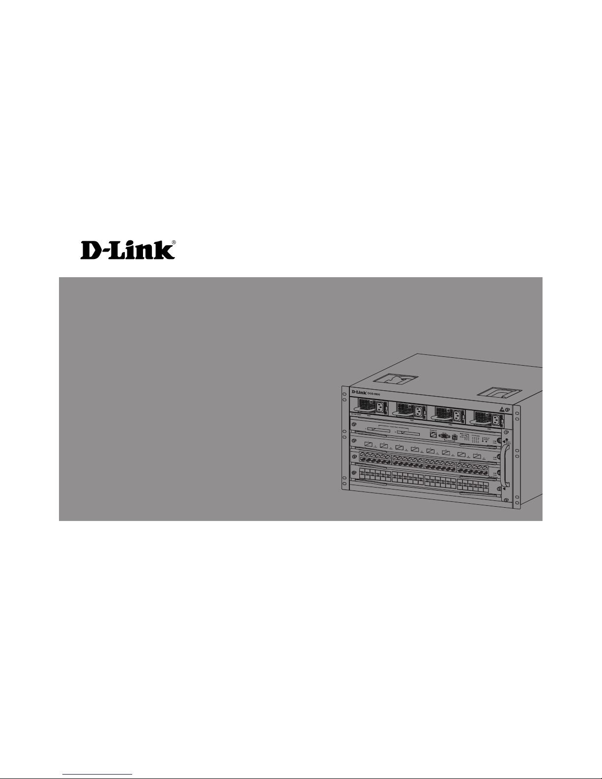
D-Link DGS-6600-48TS, DGS-6600, DGS-6600-CM, DGS-6600-48T, DGS-6600-48S Quick Installation Manual
...
This document will guide you through the basic
installation process for your new D-Link
chassis-based Switch.
Building Networks for People
DGS-6600 Series
Documentation also available on CD
and D-Link Website
Quick Installation Guide
4 Slot Chassis-Based Switch
2 u D-Link DGS-6604 Modular Switch
ENGLISH
About This Guide
This guide contains step by step instructions
for setting up the D-Link DGS-6604 chassisbased switch. Please note that the model you
have purchased may appear slightly different
from those shown in the illustrations.
Please read this manual carefully before using
the product, paying special attention to safety
warnings so as to avoid injury or damage to
equipment.
This manual is intended for users who have
experience in installing and maintaining
network hardware, and assumes that users
are familiar with standard networking terms
and concepts.
Product Overview
D-Link’s DGS-6604 chassis-based switch is
an intelligent and high-performance multi-layer
LAN device designed for enterprise campus
and metropolitan area networks (MAN). It is
ideal for deployment in environments where
uninterrupted network applications and a high
level of performance, security and control are
required.
Featuring exible modular architecture and
industry standard compliance, the switch
provides scalable expansion and a high
level of investment protection for businesses
and telecom carriers to deploy Gigabit and
10-Gigabit packet switching and routing for
ofce networking and Ethernet-based Internet
services to homes.
Warning s
Power Supply Safety Warning
Ground the device before powering on to guard against power
surges.
Be sure that all cables are grounded correctly.
Static Electricity Protection
Warning
Always wear an anti-static wrist
strap when contacting the chassis
to prevent static damage.
Laser Safety Warning
CLASS 1 LASER PRODUCT
Directly looking at the optical in-
terface or optical bers may cause
eye damage.
Fan Safety Warning
The fan mechanism is dangerous.
Avoid touching the area near the
fan.
Transportation Safety Warming
The device and components may
comprise more than 27 kg in total.
Use care when inserting or removing heaving components.
Maintenance Warning
Maintenance should only be carried out by qualied service technicians
D-Link DGS-6604 Modular Switch u 3
ENGLISH
Preparation for Installation
To ensure normal operation and prolonged life
of the DGS-6604, the appropriate temperature
and humidity must be maintained in the equipment room.
If the equipment room’s temperature and
humidity do not meet the requirements. the
equipment may sustain damage.
Operating Temperature Operating Humidity
0ºC-50ºC 10%-90% RH
non-condensed
Table 1. Temperature and Humidity
Requirements
Notes:
1. The ambient temperature and
humidity should be measured
at the point that is 1.5m above
the oor and 0.4m in front of the
equipment when there is no protective plate in front or back of the
equipment rack
2. The short-term working conditions apply where the continuous
working period does not exceed 48
hours and the cumulative total period within a year does not exceed
15 days
Static Discharge Damage Prevention
To prevent damage from static electricity,
please conform to the following guidelines:
1. Be sure to install an adequate ground for
all electronic equipment.
2. Use appropriate dust prevention measures.
3. Maintain the required humidity in the operating environment
4. Always wear an anti-static wrist strap when
working around any electronic circuitry.
5. Hold a circuit board by its edges. Do not
touch any components on the PCB.
6. Do not allow clothing to touch a circuit
board. An antistatic wrist strap can only
prevent static electricity from the human
body, but cannot mitigate static electricity
from clothing.
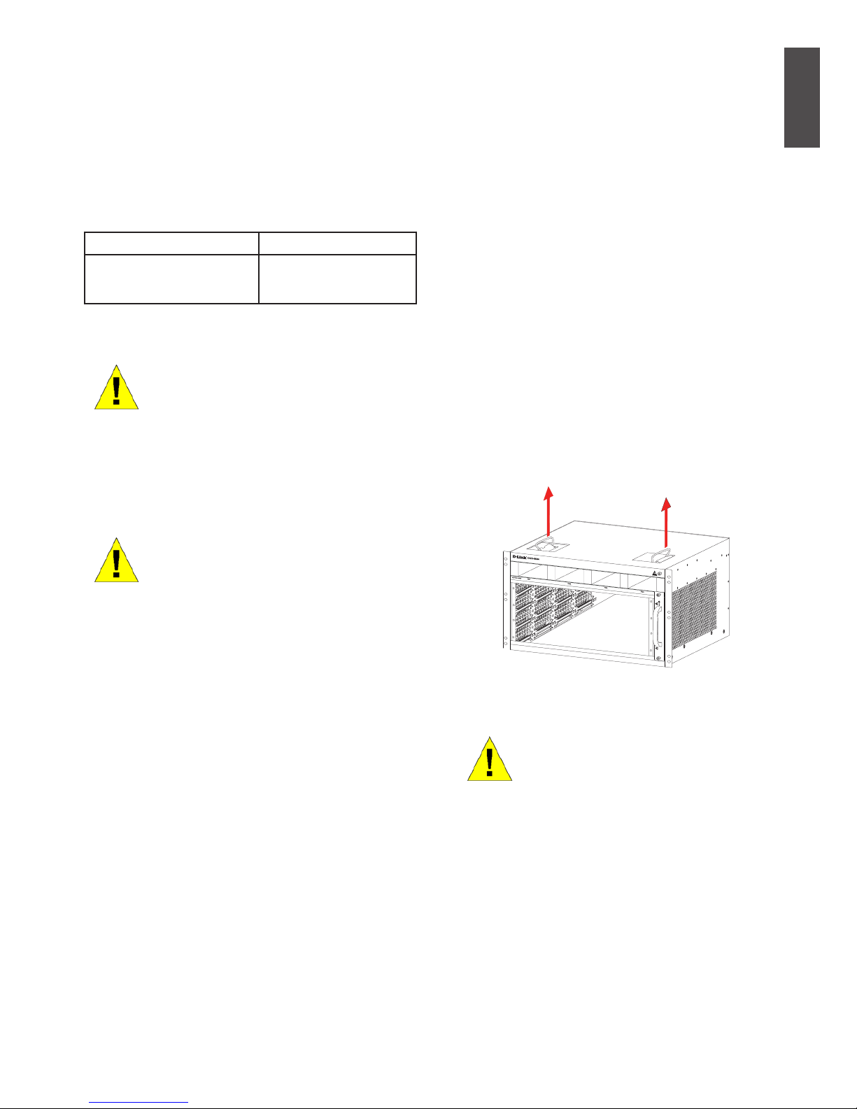
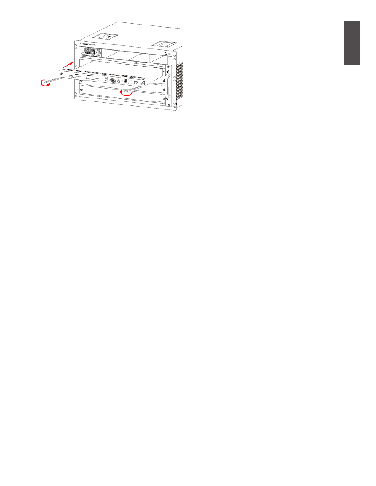
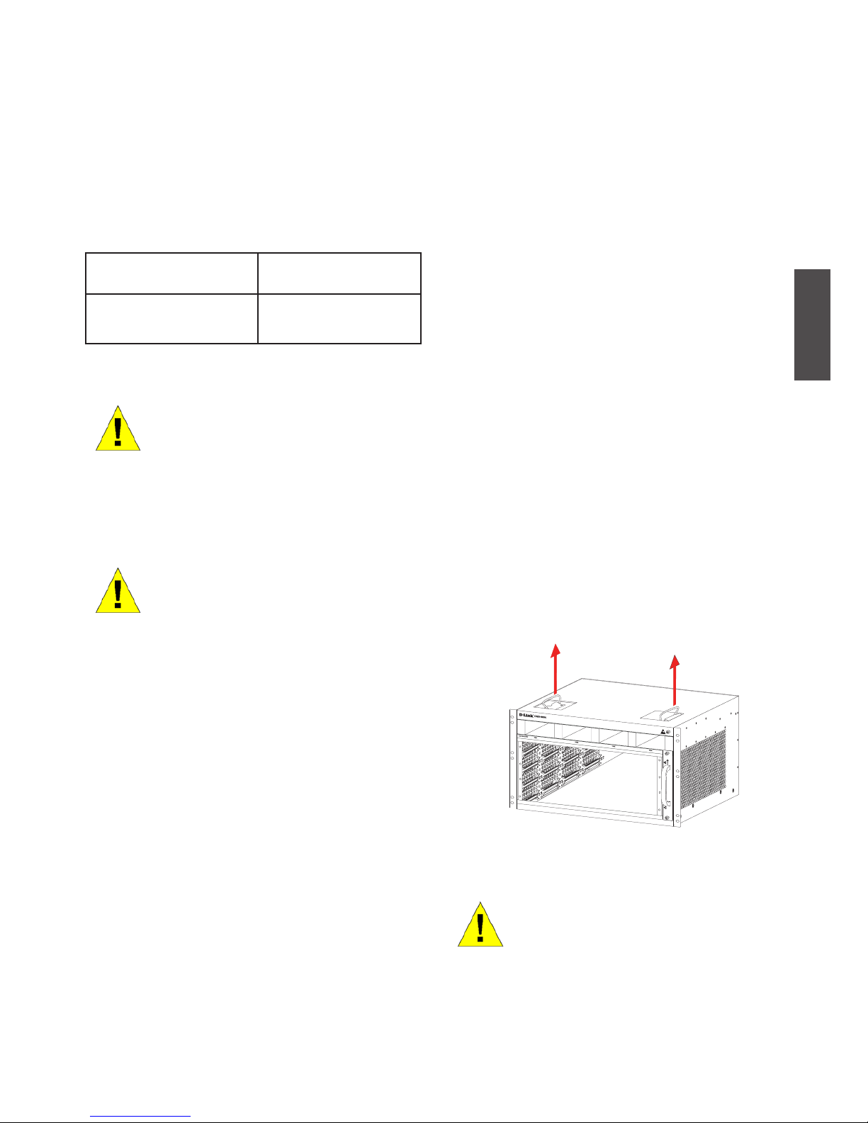
Moving the Device
The DGS-6604 is quite heavy. When handling,
please pay close attention to the following
guidelines:
• Avoid moving the equipment frequently.
• If you nd the chassis weight unbearable,
do not attempt to lift the equipment alone.
• Lift and move the chassis using the handles on the top panel .
• Turn off all power supplies and unplug all
power cables before moving the equip ment.
• Completely loosen the thumb/Phillips
screws and pull the card levers to remove
each and all line cards, fan tray, and power
mod ules from the chassis before moving it.
Figure 1. Correctly Moving the DGS-6604
Do not move the equipment by
grasping the panels, power supply handles, or ventilation holes,
as they are not designed to bear
weight.
4 u D-Link DGS-6604 Modular Switch
ENGLISH
System Grounding Requirements:
Proper grounding will help to ensure stable
and reliable operation of the DGS-6604. Be
sure to verify that the grounding conditions
at the installation meet the grounding
requirements and ground all devices
appropriately.
Ground Connection
Power Requirements
The power consumption and heat dissipation
gures of the various DGS-6604 components are
listed in the table below:
DGS-6600 Series
Module
Maximum
Power
Consumption
(W)
Heat
Dissipation
(BTU/Hour)
DGS-6600-CM 54 184
DGS-6600-48T 110 375
DGS-6600-48S 119 405
DGS-6600-48TS 114 390
DGS-6600-48P 873 2979
DGS-6600-8XG 200 684
DGS-6600-24SC2XS 106 360
DGS-6600-FAN
Fan Tray
43 144
DGS-6600-PWR
AC Power Supply
854
(@110VAC
or 220 VAC)
2913
(@110VAC
or 220 VAC)
Figure 2. Grounding of the DGS-6604
Note:
All grounding conductors should
be connected before the AC power
is applied to the DGS-6604 installed AC power supplies.
The DGS-6604 with AC power
supplies must be grounded with
a minimum of 0.823 mm2 (or
18AWG) of conductive grounding cable. This cable is connected
between the Equipment Room
Ground and the DGS-6604 Chassis Ground Terminal.
Table 2. Card Power Requirements
Note:
The DGS-6604 provides either
1+1, 2+1, or 3+1 redundant AC
power supplies. D-Link
recommends to use multiple
power supplies for the equipment
to ensure continuous and stable
operation. Redundant power
supplies help to prevent
unexpected power failures.
Redundant power supplies must
be identical.
D-Link DGS-6604 Modular Switch u 5
ENGLISH
Installation Tools Requirements
Type Tools Remarks
Common
Tools
Claw hammer,
pliers
Unpack wooden
case and
transportation case.
Phillips-head
screwdriver,
straight
screwdriver,
spanner
Disassemble
chassis, power
supply, fan and
modules
Power supply
cables,
network
cables, optical
bers and
distribution
cables
Connect the
interfaces.
Ruler, long
tapeline,
marker pen
Measure the
installation position.
Bolts, diagonal
pliers, straps
Mount the chassis.
Special
purpose
tools
Anti-static tool Prevent static
electricity.
Wire stripper,
crimping pliers
Create network
cables and
grounding cables.
Meter Multimeter Test power supply
and DC resistance.
500V
Megohmmeter
Test the insulation
and grounding
resistance
Table 3. Required Tools
Installation Site
Requirements
The DGS-6604 must be used indoors. To
ensure the normal operation and prolonged
useful life of the equipment, the installation
site must meet the following requirements.
Requirements for Rack Mounting
If you plan to mount the DGS-6604 in a frame,
please observe the following guidelines:
• Install the switch in an open cabinet if
pos sible. If you install the switch inside
a closed cabinet please ensure that the
cabi net has a good ventilation and heat
dissipation system.
• Ensure that the cabinet is durable enough
to bear the weight of the DGS-6604 and its
installation accessories.
• Ensure that the dimensions of the cabinet
provide enough space for the installation
of the front, rear, left and right panels of
the DGS-6604 for the purpose of heat
dissipation.
• The frame should be properly grounded.
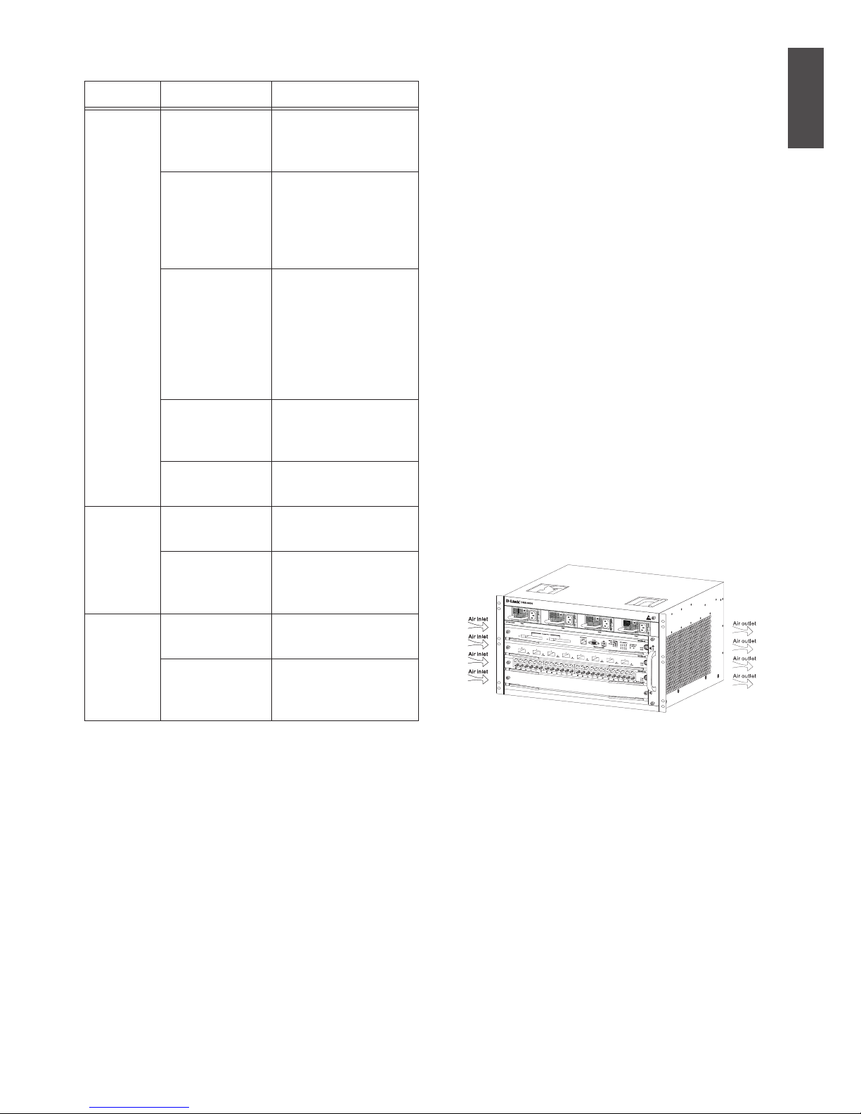
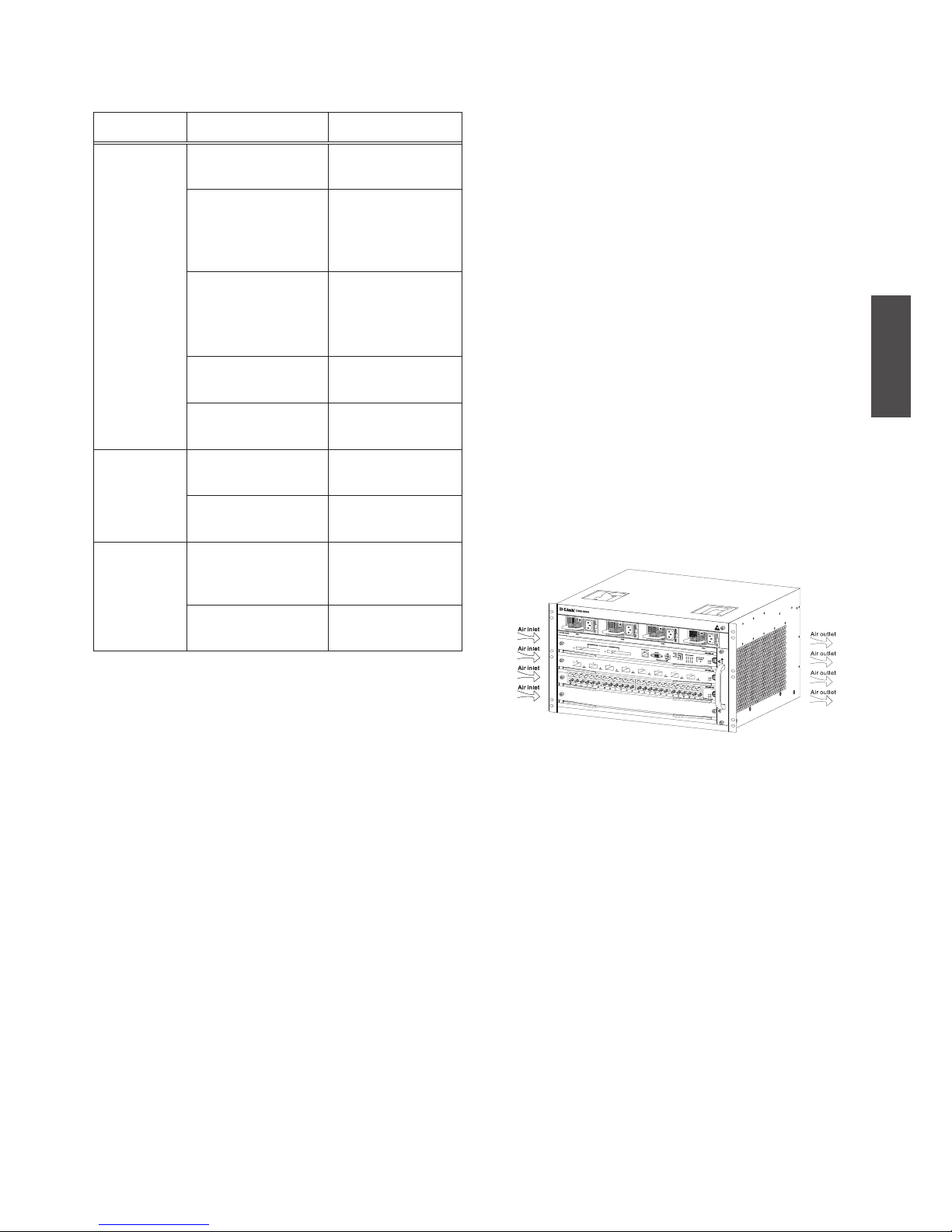
Ventilation Requirements
Following gure shows the ventilation
requirements of the DGS-6604. You must
reserve sufcient space near the vents to
ensure proper ventilation. After the cables
have been connected, they should be
arranged into bundles or placed on the cabling
rack to prevent the obstruction of air intakes
and vents.
Figure 3. Ventilation of the DGS-6604
Mounting the DGS-6604 into the Cabinet
1. Lift the chassis (seek assistance if the
chassis is more then you can lift safely)
while keeping it level Slowly move it to the
front of the frame.
2. Keeping the DGS-6604 level, lift it to a
posi tion slightly higher than the tray of the
slide rail of the cabinet. Set the chassis
onto the tray or the slide rail, and push it
into the cabinet.
3. Fasten the DGS-6604 to the cabinet with
screws. Fastening notches are on both the
left and right sides of the front panel on the
6 u D-Link DGS-6604 Modular Switch
ENGLISH
equipment frame. Use screws to fasten
them to the bracket of the cabinet/ Once
fastened, the equipment should be stable
and immobile.
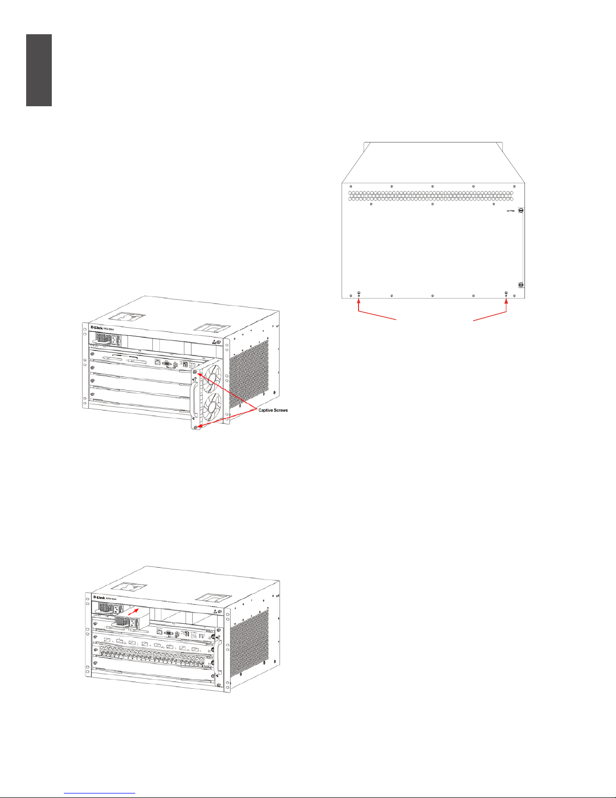
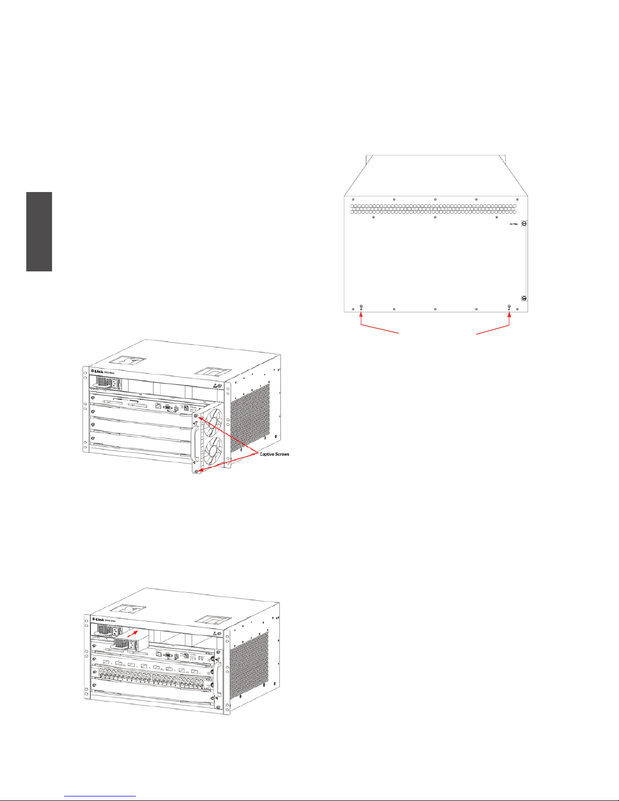
Installing the Fan Tray
The DGS-6600-FAN fan tray is used as the
DGS-6604’s ventilation system. Carry out the
following to install the fan tray:
1. Use the thumb-screws to remove the fan
tray blank panel.
2. Insert the fan tray into the guide rail of the
fan tray slot.
3. Secure the fan tray by tightening the fan
tray’s captive-screws.
Figure 4. Installing the Fan Tray
Installing the Power Supply(s)
The DGS-6604 switch is powered up using an
AC power supply. The procedure for installing
the AC power supply is shown in the diagram
below:
Figure 5. Installing the Power Supply
Connecting the System Ground
A working ground GND is installed on the back
of DGS-6604. GND should be directly
connected to the ground bar of the equipment
room. If a digital grounding bar and an analog
grounding bar exist in the equipment room, the
GND should be connected to the digital bar.
Ground Connection
Figure 6. Ground Connections on the back of the
DGS-6604
Precautions.
The sectional area of the grounding cable
(min. of 18AWG) should be selected to safely
conduct the maximum possible current. Use
insulated cables of good conductivity.
• Do not use bare wire.
• The grounding resistance for combined
grounding should be less than 1 Ohm (Ω).
Simple Grounding Steps
• Unfasten the nut on the rear grounding
post of the equipment.
• Afx the terminal of the grounding cable to
the grounding pole.
• Fasten the nut back on the grounding post.
• Connect the other end of the grounding
cable to a suitable grounding bar.
D-Link DGS-6604 Modular Switch u 7
ENGLISH
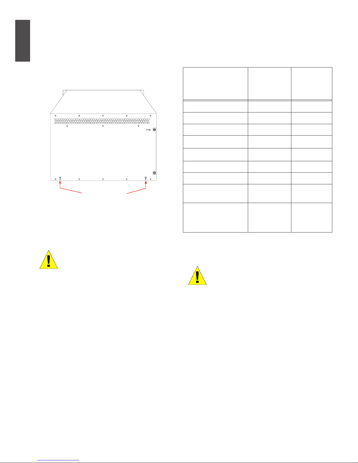
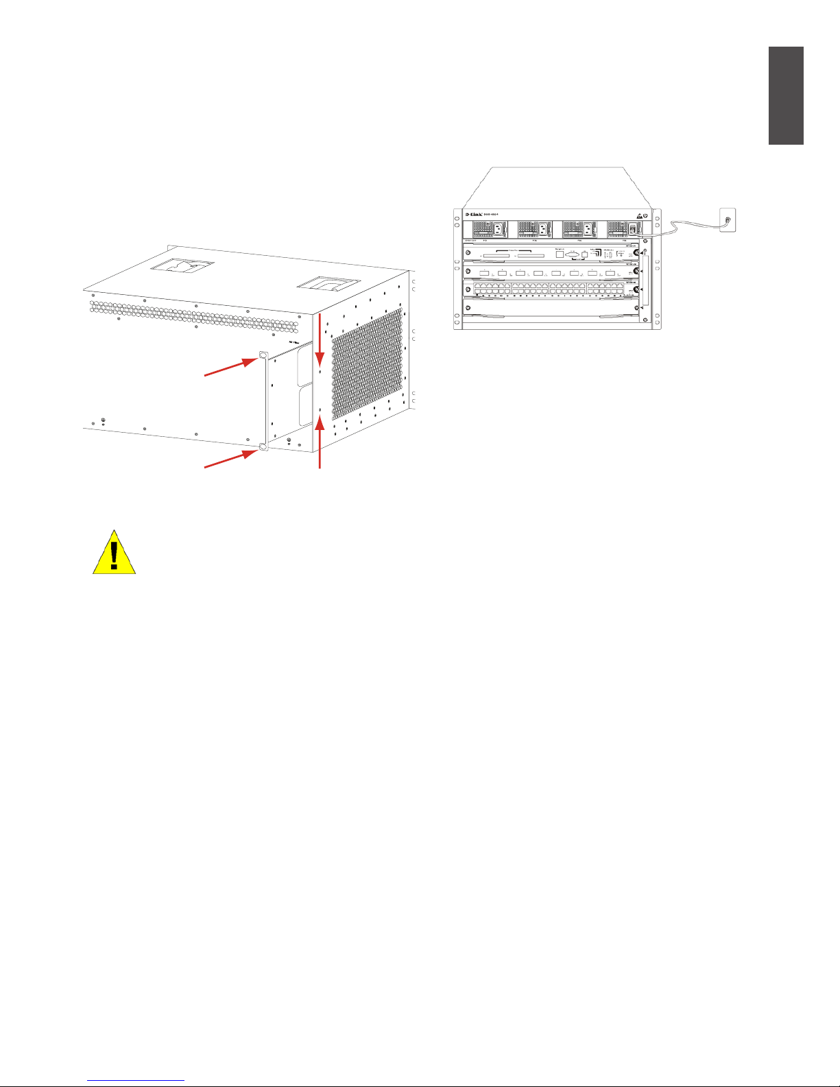
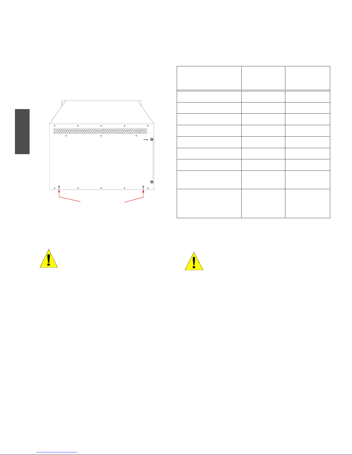
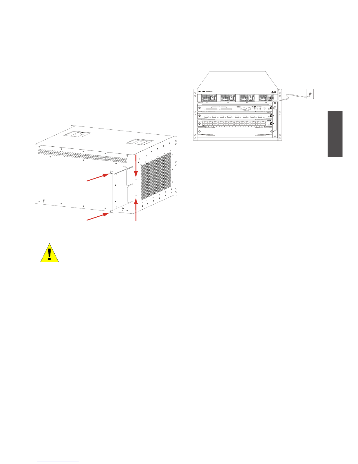
Installing the Air Filter of the DGS-6604
On the back of the chassis on the edge of the
right-side is a vertical slot where the air lter
can be tted. Slide in a cleaned or new air lter
into the slot as per the following diagram. Then
screw the two thumb/Phillips screws (see the
diagram arrows) to secure the air lter into the
chassis. With the air lter installed screw-in two
screws on the side of the chassis as indicted
by the red arrows in the diagram.
Figure 7. Installing the Air Filter
Air lter installation is recommended as the last step of the chassis
installation.
Connecting the AC Power Supply to the
Power Module
Use the related AC power cable to connect to
the AC power module panel, as indicated in
the following diagram:
Figure 8. Connecting AC to the Power Module
AC Power Supply Connection Precaution
• Verify that the provided external power
sup ply matches the power module installed
in the Switch before connecting the power
supply.
• Use a power cable with a standard 3-pin
connector to make the power connection.
• Ensure that the connected power cables
have good contacts.
• Once the power cable is plugged-in at both
power outlet and the power supply, the
power supply will immediately start.
Simple AC Power Connection Steps
1. Insert the power cable’s plug into the
power module.
2. Secure the power cable to the cable clip on
the right.
3. Connect the other end of the power cable
into the corresponding socket or connector.
8 u D-Link DGS-6604 Modular Switch
ENGLISH
Connecting the Serial Cable of the Management Module
Simple CPU Module Cable Connection
1. Connect the RJ45 connector of an Ethernet
cable to the Ethernet port of the Switch’s
management module (DGS-6600-CM) and
connect the other end of the cable to any
TCP/IP capable device that is able to execute Telnet or SSH.
- or -
2. Connect the standard DB9 end of the
serial cable to the RS-232 serial port of
the Switch’s management module and the
other end to the PC/Notebook or control
terminal.
- or -
3. Connect a USB cable with a USB Standard
B Connector to the Standard B receptacle
on the Switch’s management module. Connect the other end to a computer equipped
with a USB port capable of supporting a
serial interface using the PL-2303 USB
Serial Driver SW from Prolic Technology
Inc..
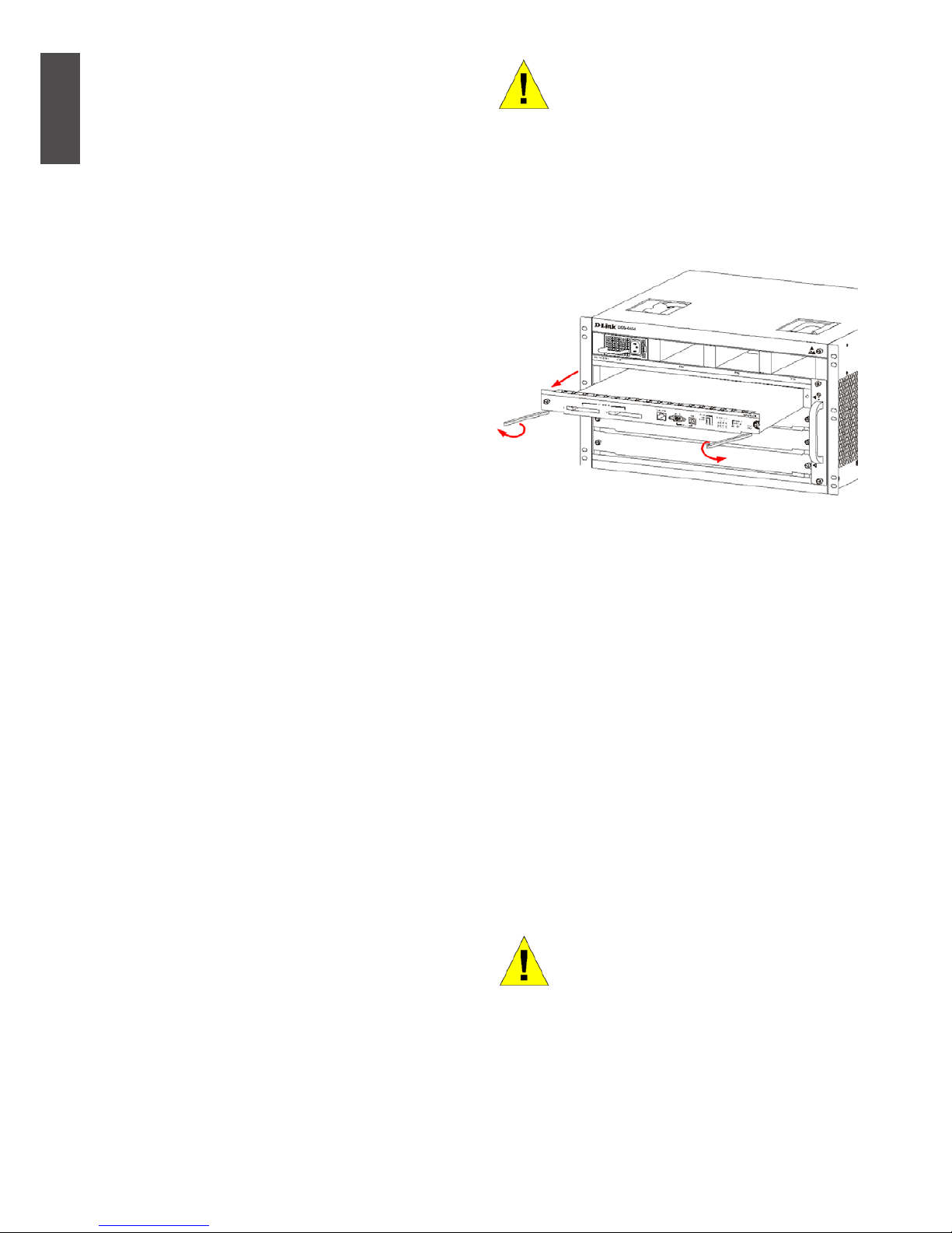
Removing Boards from the DGS-6604
Carry out the following steps to remove boards
from the DGS-6604:
1. Unplug all copper/ber cabling, i.e. RJ45
twisted-pair and ber optic cables, from the
board to be removed.
2. Loosen and unscrew the panel’s two captive screws.
3. Use both hands to pull the levers, on the
left and right hand sides of the board, to
remove the board from the DGS-6604, as
shown in the following diagram.
Caution
Before removing/adding a board,
always wear an anti-static wrist
strap.
Take care not to hold the edge of
the PCB or collide the components
of the PCB..
Figure 9. Removing a board from the chassis
Installing Boards on the DGS-6604
Carry out the following steps to install boards
in the DGS-6604:
1. Remove the component card or blank panel
as instructed in the section.
2. Insert the new board into the guide rail of
the vacant slot.
3. Use the levers on the left and right hand
side to push the board into position and
tighten the two captive screws on the board
using a straight screw driver.
Caution
1. Take care not to hold the
edge of the PCB or collide the
compo nents of the PCB.
2. Always use the levers to plug/
unplug a PCB module. Never
use force to remove a PCB
module.
D-Link DGS-6604 Modular Switch u 9
ENGLISH
Figure 10. Installation Check
Installation Check
Verify that the external AC power supply
provides the correct voltage and frequency.
Verify that the cabinet has been fastened
completely, and does not move or tilt.
Verify that the Power Supplies, CM and Line
Cards have been installed in the chassis.
Verify that the optical ber and twisted pair
cables match their respective interfaces.
Verify that the cables have been bound
appropriately and are not subject to any
excess stress.
Verify that the power cables are in good
condition and comply with safety requirements.
Verify that the power module has been rmly
installed into the backplane connector.
Turn on the power switch and verify that the
power module is operating correctly.
Unpacking Inspection
Requirements
Checklist
1. DGS-6604 Chassis Carton
• DGS-6604 Chassis (no cards installed)
1. Card Module Carton (s)
• 1 CM Card DGS-6600-CM
• Line Cards (specic per order)
• Power Supplies Units (number specic per
order)
2. DGS-6604 Accessories Carton including:
• AC Power Cord
• RS-232 Console Cable (9 pin D-Sub)
• USB Console Cable (Type A to Type B)
• Fan Tray
• Air Filter
• CD software and manual
• QIG
Management Options
The system may be managed out-of-band
through the console port(s) and Ethernet port
on the Control Module or in-band using Telnet/
SSH. Each Switch must be assigned its own IP
address, which is used for communication with
an SNMP network manager or other TCP/IP
application (for example BOOTP, TFTP). The
Switch’s default IP address is 10.90.90.90 (outof-band IP address). The user can change the
default IP address to meet the specications of
your networking address scheme.
Connecting the Console Port (USB or 9
Pin D-Sub)
The switch provides a USB or 9 Pin D-Sub
Serial Connection to a computer or terminal
for monitoring and conguration. To use
the console port, you need the following
equipment:
• A terminal or a computer with a 9 pin serial
port /USB port and the ability to emulate a
terminal.
• A null modem or cross-over RS-232 cable
with a female DB-9 connector for the
switch’s console port.
- or -
10 u D-Link DGS-6604 Modular Switch
ENGLISH
• A USB cable (with a Type B USB connector
for the switch’s USB console port) and the
Serial USB driver installed on the computer
used to connect to the console.
Download the USB-Serial Driver here:
http://www.prolic.com.tw/eng/
downloads.asp?ID=31
Conrm the driver for your Operating
System is for the X chip series.
To connect a terminal to the console port
1. Connect the supplied RJ-45-to DB-9 adapter cable to the standard 9-pin serial port on
the PC. Connect the other end of the cable
to the console port on the switch. Set the
terminal emulation software as fol lows:
• Baud rate: 115200
• Data bits: 8
• Parity: None
• Stop bits: 1
• Flow control: None
2. Select VT100 for the terminal emulation
mode.
3. After you have correctly set up the terminal,
plug the power cable into the power supplies on the switch. The boot sequence will
appear in the terminal.
4. Press the Enter key at the password
prompts. There is no default password for
the Switch.
5. Enter the commands to complete your desired tasks. Many commands require administrator-level access privileges. See the
CLI Reference Guide on the documen tation
CD for a list of all commands and additional
information using the CLI.
Telnet Management Users may also access
the switch CLI by using PC’s Command Prompt.
To access it from your computer, users must rst
ensure that a valid connection is made through
the Ethernet port of the Switch and your PC,
and then click Start > Programs > Accessories >
Command Prompt on your computer. Once the
console window opens, enter the command
telnet 10.90.90.90 (depending on congured
IP address) and press Enter on your keyboard.
You should be directed to the opening console
screen for the CLI of the switch, press the Enter key at the password prompts. There is no
default password for the Switch.
SNMP-Based Management
You can manage the Switch with D-Link
D-View or any SNMP-compatible console
program. The SNMP function is disabled by
default for D-Link managed switches.
Additional Information
If you are encountering problems setting up
your network, please refer to the User’s Guide
that comes with the switch. It contains many
more rules, charts, explanations and examples
to help you get your network up and running.
Additional help is available through our ofces listed online. To learn more about D-Link
products or marketing information, please visit
the website http://www.dlink.com, which will
re-direct you to your appropriate local D-Link
website.
Technical Support
United Kingdom (Mon-Fri)
website: http://www.dlink.co.uk
FTP: ftp://ftp.dlink.co.uk
Home Wireless/Broadband 0871 873 3000
(9.00am–06.00pm, Sat 10.00am-02.00pm)
Managed, Smart, & Wireless Switches, or
Firewalls 0871 873 0909 (09.00am- 05.30pm)
(BT 10ppm, other carriers may vary.)
Ireland (Mon-Fri)
All Products 1890 886 899 (09.00am-06.00pm,
Sat 10.00am-02.00pm)
Phone rates: €0.05ppm peak, €0.045ppm off
peak times
Diese Anleitung führt Sie durch den allgemeinen
Installationsprozess für Ihren neuen Chassis
Switch von D-Link.
Building Networks for People
DGS-6600 Series
Documentation also available on CD
and D-Link Website
Schnellinstallationsanleitung
Chassis basierter Switch mit 4 Steckplätzen
12 u D-Link DGS-6604 Modular Switch
DEUTSCH
Informationen zum
Handbuch
Dieses Handbuch enthält schrittweise
Anleitungen zum Einrichten des Chassis
Switch der D-Link DGS-6604 Produktreihe.
Beachten Sie, dass Ihr Modell sich
möglicherweise geringfügig von den
Abbildungen unterscheidet.
Bitte lesen Sie dieses Handbuch sorgfältig
durch, bevor Sie das Produkt verwenden,
und achten Sie besonders auf die
Sicherheitswarnungen, um Verletzungen oder
Beschädigungen des Geräts zu vermeiden.
Dieses Handbuch richtet sich an Personen,
die Erfahrung mit der Installation und
Wartung von Netzwerk-Hardware haben.
Ein Verständnis der gängigen Begriffe und
Konzepte von Netzwerken wird vorausgesetzt.
Produktübersicht
Der Chassis Switch der D-Link DGS6604-Produktreihe ist ein intelligentes,
hochleistungsfähiges, Multi-Layer LAN-Gerät
für Unternehmensnetzwerke und Metropolitan
Area Networks (MAN). Es ist speziell für
den Einsatz in Umgebungen ausgelegt, in
denen eine unterbrechungsfreie Ausführung
von Netzwerkanwendungen sowie ein hohes
Maß an Leistung, Sicherheit und Steuerung
erforderlich sind.
Mit seiner exiblen modularen
Architektur und der Kompatibilität mit
Industriestandards bietet der Switch
skalierbare Erweiterungsmöglichkeiten bei
hohem Investitionsschutz für Unternehmen
und Telekommunikationsbetreiber, die
Paketvermittlung und Routing über Gigabit
und 10-Gigabit für Büronetzwerke sowie
Ethernet-basierte Internetdienste für
Privatnutzer bereitstellen möchten.
Warnhinweise
Sicherheitshinweise zur Stromversorgung
Erden Sie das Gerät vor dem Einschalten, um Stromüberspannungen zu vermeiden.
Stellen Sie sicher, dass alle Kabel
richtig geerdet sind.
Warnhinweise zum Schutz vor
statischer Auadung
Tragen Sie beim Berühren des
Gehäuses immer ein Erdungsarmband, um Schäden durch statische
Auadung zu vermeiden.
Sicherheitswarnung zum Laser
LASERPRODUKT DER KLASSE 1
Sehen Sie nie direkt auf die Glas-
faserleiter oder -komponenten,
da dies zu Augenschäden führen
kann.
Sicherheitswarnung zum Lüfter
Der Lüftermechanismus ist gefährlich. Berühren Sie das Gerät nicht
in der Nähe des Lüfters.
Sicherheitswarnung zum Transport
Das Gerät einschließlich der Komponenten kann mehr als 27 kg
wiegen.
Gehen Sie beim Einsetzen oder
Heben von Komponenten vorsichtig vor.
Warnungshinweis zur Wartung
Wartungsarbeiten dürfen nur von
qualizierten Servicetechnikern
vorgenommen werden.
D-Link DGS-6604 Modular Switch u 13
DEUTSCH
Installationsvorbereitung
Zur Gewährleistung eines normalen Betriebs
und einer möglichst langen Lebensdauer des
DGS-6604 müssen die passenden Werte für
Temperatur und Luftfeuchtigkeit im Geräteraum
eingehalten werden.
Bei einer unangemessenen Temperatur oder
Luftfeuchtigkeit im Geräteraum können Schäden am Gerät entstehen.
Betriebstemperatur Luftfeuchtigkeit (bei
Betrieb)
0ºC - 50ºC 10%-90% RF, nicht
kondensierend
Tabelle 1. Erforderliche Temperatur und Luft-
feuchtigkeit
Hinweise:
1. Wenn sich keine Schutzblende
vor oder hinter dem Geräterack bendet, sollten die Umgebungstemperatur und die Luftfeuchtigkeit an
einer Stelle gemessen werden, die
sich 1,5 m oberhalb des Bodens
und 0,4 m vor dem Gerät bendet.
2. Die Werte für die kurzfristigen
Bedingungen gelten, wenn die
durchgängige Betriebszeit nicht
mehr als 48 Stunden beträgt und
die Gesamtbetriebszeit innerhalb
eines Jahres 15 Tage nicht überschreitet.
Verhindern von Schäden durch statische
Entladung
Beachten Sie die folgenden Richtlinien, um Schäden durch statische Auadung zu vermeiden:
1. Alle elektronischen Geräte müssen ausreichend geerdet werden.
2. Staubansammlungen müssen durch geeignete Maßnahmen vermieden werden.
3. In der Betriebsumgebung muss eine angemessene Luftfeuchtigkeit vorherrschen.
4. Tragen Sie bei der Arbeit an elektronischen
Schaltkreisen immer ein Erdungsarmband.
5. Fassen Sie Leiterplatten nur an den Kanten
an. Berühren Sie keine Komponenten auf
Leiterplatten.
6. Achten Sie darauf, dass Leiterplatten nicht
mit Kleidung in Berührung kommen. Ein
Erdungsarmband kann nur statische Aufladung vermeiden, die vom menschlichen
Körper stammt, sie kann jedoch nicht die
von Kleidung verursachte statische Auadung abschwächen.
Transport des Geräts
Der DGS-6604 hat ein beträchtliches Gewicht.
Beachten Sie deshalb bei Handhabung und
Transport unbedingt die folgenden Anweisungen:
• Das Gerät sollte möglichst selten transportiert werden.
• Sollte ein Heben des Chassis zu beschwerlich sein, versuchen Sie nicht, das Gerät
alleine zu heben oder zu transportieren.
• Heben und transportieren Sie das Chassis
mithilfe der Tragegriffe auf der Deckenplatte.
• Vor dem Transport des Geräts müssen alle
Netzteile bzw. Stromversorgungsgeräte
ausgeschaltet und alle Stromkabel abgezogen werden.
• Lösen Sie die Finger-/Kreuzschlitzschrauben ganz und ziehen Sie die Card-Hebel
heraus, um alle Linecards, Lüfterfächer und
Leistungsmodule vom Chassis zu entfernen, bevor Sie das Gehäuse transportieren.
Abbildung 1. Ordnungsgemäßer Transport des
DGS-6604
Halten Sie das Gerät beim Transport nicht an den Blenden, den
Griffen des Netzteils oder den
Lüftungsöffnungen, da diese Bauteile kein großes Gewicht tragen
können.
14 u D-Link DGS-6604 Modular Switch
DEUTSCH
Erdungsvoraussetzungen für das
System:
Eine ordnungsgemäße Erdung trägt zum
stabilen und zuverlässigen Betrieb des
DGS-6604 bei. Stellen Sie sicher, dass die
Erdungsbedingungen bei der Installation den
Erdungsanforderungen entsprechen, und
sorgen Sie für eine entsprechende Erdung der
Geräte.
Ground Connection
Leistungsbedarf
Stromverbrauchs- und Wärmeableitungswerte der
verschiedenen Komponenten des DGS-6604 sind in
der Tabelle weiter unten aufgeführt:
DGS-6600 Produktreihe
Modul
Maximaler
Stromverbrauch
(W)
Wärmeableitung
(BTU/Stunde)
DGS-6600-CM 54 184
DGS-6600-48T 110 375
DGS-6600-48S 119 405
DGS-6600-48TS 114 390
DGS-6600-48P 873 2979
DGS-6600-8XG 200 684
DGS-6600-24SC2XS 106 360
DGS-6600-FAN
Lüfterfach
43 144
DGS-6600-PWR
Netzteil (Wechselstrom)
854
(@110 oder
220 Volt)
2913
(@110 oder
220 Volt)
Abbildung 2. Erden des DGS-6604
Hinweis:
Alle Erdleiter müssen angeschlossen sein, bevor Wechselstrom den
im DGS-6604 installierten Netzteilen zugeführt wird.
Der DGS-6604 mit Netzteilen
muss mit einer Erdungsleitung
von mindestens 0.823 mm² (oder
18 AWG) geerdet sein. Diese
Kabelleitung verbindet die Erdung
des Geräteraums und den DGS6604 Chassis-Erdungsanschluss
(Masseanschluss).
Tabelle 2. Leistungsbedarf (Card Power)
Hinweis:
Der DGS-6604 bietet entweder
1+1, 2+1 oder 3+1 redundante
Netzteile. D-Link empehlt den
Einsatz mehrerer Netzteile, um
den unterbrechungsfreien und
stabilen Betrieb des Geräts zu
gewährleisten. Redundante
Netzteile tragen dazu bei,
unerwartete Stromausfälle
weitgehend zu verhindern. Die für
die redundante Stromversorgung
verwendeten Netzteile müssen
identisch sein.
D-Link DGS-6604 Modular Switch u 15
DEUTSCH
Voraussetzungen und Anforderungen für
die Verwendung der Installationswerkzeuge
Art Werkzeuge Anmerkungen
Allgemeine
Werkzeuge
Klauenhammer, Zange Auspacken der Holzkiste
und der Transportkiste
Kreuzschlitzschraubenzieher,
gerader Schraubenzieher,
Schraubenschlüssel
Auseinanderbauen von
Chassis (Gehäuse),
Netzteil, Lüfter und
Modulen
Netzgerätekabel,
Netzwerkkabel,
Glasfaserkabel und
Verteilerkabel
Verbinden der
Schnittstellen
Lineal, langes Maßband,
Markierstift
Abmessen der
Installationsposition
Schrauben,
Diagonalzange, Riemen
Chassis-Montage
Spezialwerkzeuge
Erdungsmaterial Verhindern von statischer
Auadung
Abisolierzange, Crimpzange Herstellen von Netzwerk-
und Erdungskabeln
Messgerät Multimeter Testen der
Stromversorgung und des
Gleichstromwiderstands
500 V Megohmmeter Testen des Isolations- und
Erdungswiderstands
Tabelle 3. Erforderliche Werkzeuge
Voraussetzungen des
Installationsstandorts
Der DGS-6604 muss in Innenräumen
verwendet werden. Zur Gewährleistung eines
normalen Betriebs und einer möglichst langen
Lebensdauer muss der Installationsstandort
die folgenden Voraussetzungen erfüllen.
Voraussetzungen für die Rackmontage
Wenn das DGS-6604 mm einem Rahmen
montiert werden soll, beachten Sie die
folgenden Richtlinien:
• Installieren Sie den Switch nach
Möglichkeit in einem offenen Schrank.
Wenn der Switch in einem geschlossenen
Schrank installiert wird, ist auf eine
ausreichende Lüftung und Wärmeableitung
zu achten.
• Der Schrank muss das Gewicht
des DGS-6604 einschließlich des
Installationszubehörs tragen können.
• Im Schrank muss ausreichend Platz zum
Anbringen der vorderen, hinteren, rechten
und linken Blenden des DGS-6604
vorhanden sein, um die Wärmeableitung
zu ermöglichen.
• Der Rahmen muss ordnungsgemäß
geerdet werden.
Lüftungsanforderungen
In der folgenden Abbildung werden die
Lüftungsanforderungen des DGS-6604
gezeigt. In der Nähe der Lüftungsöffnungen
muss sich ausreichend Platz benden, um
eine ordnungsgemäße Belüftung zu
ermöglichen. Die angeschlossenen Kabel
sollten in Bündeln zusammengefasst oder im
Kabelfach platziert werden, damit sie die
Lufteinlässe für die Zuluft und
Lüftungsöffnungen nicht versperren.
Abbildung 3. Belüftung des DGS-6604
Montage des DGS-6604 im Schrank
1. Heben Sie das Chassis ohne zu kippen
(bitten Sie um Hilfe, wenn Ihnen ein sicheres Heben des Chassis nicht möglich ist).
Bewegen Sie das Gehäuse langsam zur
Vorderseite des Rahmens.
2. Halten Sie das DGS-6604 waagerecht und
heben Sie es etwas über den Einschub
oder die Führungsschiene des Schranks.
Setzen Sie das Chassis auf dem Einschub
oder der Führungsschiene ab und schieben
Sie es in den Schrank.
3. Befestigen Sie das DGS-6604 mit Schrau-
16 u D-Link DGS-6604 Modular Switch
DEUTSCH
ben am Schrank. An der linken und rechten
Seite der Vorderblende des Geräterahmens
benden sich Befestigungskerben. Verwenden Sie Schrauben zur Befestigung an der
Schrankhalterung. Anschließend sollte das
Gerät stabil und unbeweglich sein.
Installation des Lüfterfachs
Das Lüfterfach DGS-6600-FAN bildet das
Lüftungssystem des DGS-6604. Gehen Sie
wie folgt vor, um das Lüfterfach zu installieren:
1. Entfernen Sie die Leerblende des
Lüfterfachs, indem Sie die unverlierbaren
Schrauben lösen.
2. Setzen Sie das Lüfterfach
auf die Führungsschiene des
Lüfterfachsteckplatzes.
3. Befestigen Sie das Lüfterfach durch
Anziehen seiner unverlierbaren Schrauben.
Abbildung 4. Installation des Lüfterfachs
Installieren des Netzteils/der Netzteile
Die Stromversorgung des DGS-6604 Switch
erfolgt über ein Netzteil. Die Abbildung unten
zeigt die Installation des Netzteils:
Abbildung 5. Installation des Netzteils
Anschließen der Systemerdung
An der Rückseite des DGS-6604 bendet sich
ein GND-Anschluss (Betriebserdung). GND
muss direkt mit der Erdungsschiene des
Geräteraums verbunden werden. Wenn eine
digitale und eine analoge Erdungsschiene im
Geräteraum vorhanden ist, sollte GND mit der
digitalen Schiene verbunden werden.
Ground Connection
Abbildung 6. Masseanschlüsse auf der Rückseite
des DGS-6604
Die Querschnittsäche des Erdungskabels
(min. 18 AWG (American Wire Gauge/0,79 mm
gemäß AWG Datentabelle) sollte nach sicherer
Leitung der größtmöglichen Stromspannung
ausgewählt werden. Verwenden Sie isolierte
Kabel mit hoher Leitfähigkeit.
• Verwenden Sie keinen Blankdraht.
• Der Erdungswiderstand für eine
kombinierte Erdung muss weniger als 1
Ohm (Ω) betragen.
Einfache Erdungsschritte
• Lösen Sie die Mutter an der hinteren
Erdungsklemme des Geräts.
• Befestigen Sie den Anschluss des
Erdungskabels am Erdungsstab.
• Ziehen Sie die Befestigungsmutter wieder
an der Erdungsklamme an.
• Schließen Sie das andere Ende des
Erdungskabels an eine geeignete
Erdungsschiene an.
D-Link DGS-6604 Modular Switch u 17
DEUTSCH
Installation des Luftlters des DGS-6604
Auf der Rückseite des Chassis am rechten
Seitenrand bendet sich ein vertikaler Schlitz
zur Installation des Luftlters. Schieben Sie,
wie in der folgenden Abbildung dargestellt,
einen gereinigten oder neuen Luftlter in den
Steckplatz. Befestigen Sie dann den Luftlter
am Chassis mithilfe der zwei Finger-/
Kreuzschlitzschrauben (siehe Pfeile auf der
Abbildung). Sobald der Luftlter eingesetzt ist,
befestigen Sie ihn mit zwei Schrauben an der
Seite des Chassis, wie durch die roten Pfeile
in der Abbildung dargestellt.
Abbildung 7. Installation des Luftlters
Der Luftlter sollte Im Anschluss
an die Installation aller anderen
Komponenten im Chassis installiert werden.
Anschließen des Netzteils an die
Stromversorgung
Verwenden Sie das entsprechende Netzkabel
zum Anschluss an die Wechselstromversorgung,
wie in der folgenden Abbildung dargestellt:
Abbildung 8. Wechselstrom zum Netzteil
Warnhinweise zum Anschluss des Netzteils
• Vor dem Anschluss des Netzteils muss
sichergestellt werden, dass das im
Lieferumfang enthaltene Netzteil zur
existierenden Wechselstromversorgung
passt.
• Verwenden Sie nur ein Stromkabel mit
einem 3-poligen Standardstecker.
• Die angeschlossenen Stromkabel müssen
gute Kontakte aufweisen.
• Sobald das Netzkabel an die Steckdose
und das Netzteil angeschlossen ist, beginnt
die Stromzufuhr.
Einfache Schritte zum
Wechselstromanschluss
1. Stecken Sie den Stecker des Stromkabels
in das Netzteil.
2. Sichern Sie das Stromkabel mithilfe der
Stromkabelklemme auf der rechten Seite.
3. Stecken Sie das andere Ende des
Stromkabels in die entsprechende
Steckdose oder Buchse.
 Loading...