

Page 1
Page 2

Information in this document is subject to change without notice.
© 2013 D-Link Corporation. All rights reserved.
Reproduction in any manner whatsoever without the written permission of D-Link Corporation is strictly forbidden.
Trademarks used in this text: D-Link and the D-LINK logo are trademarks of D-Link Corporation; Microsoft and Windows are registered trademarks of
Microsoft Corporation.
Other trademarks and trade names may be used in this document to refer to either the entities claiming the marks and names or their products. D-Link
Corporation disclaims any proprietary interest in trademarks and trade names other than its own.
February, 2013 P/N 651GS3420035G
FCC Warning
This equipment has been tested and found to comply with the limits for a Class A digital device, pursuant to Part 15 of the
FCC Rules. These limits are designed to provide reasonable protection against harmful interference when the equipment
is operated in a commercial environment. This equipment generates, uses, and can radiate radio frequency energy and, if
not installed and used in accordance with this manual, may cause harmful interference to radio communications.
Operation of this equipment in a residential area is likely to cause harmful interference in which case the user will be
required to correct the interference at his own expense.
CE Mark Warning
This is a Class A product. In a domestic environment, this product may cause radio interference in which case the user
may be required to take adequate measures.
Warnung!
Dies ist ein Produkt der Klasse A. Im Wohnbereich kann dieses Produkt Funkstoerungen verursachen. In diesem Fall
kann vom Benutzer verlangt werden, angemessene Massnahmen zu ergreifen.
Precaución!
Este es un producto de Clase A. En un entorno doméstico, puede causar interferencias de radio, en cuyo case, puede
requerirse al usuario para que adopte las medidas adecuadas.
Attention!
Ceci est un produit de classe A. Dans un environnement domestique, ce produit pourrait causer des interférences radio,
auquel cas l`utilisateur devrait prendre les mesures adéquates.
Attenzione!
Il presente prodotto appartiene alla classe A. Se utilizzato in ambiente domestico il prodotto può causare interf eren ze
radio, nel cui caso è possibile che l`utente debba assumere provvedimenti adeguati.
VCCI Warning
この装置は、クラス A 情報技術装置です。この装置を家庭環境で使用すると電波妨害を引き起こすことがあります。こ
の場合には使用者が適切な対策を講ずるよう要求されることがあります。 VCCI-A
BSMI Notice
此為甲類的資訊技術設備,在居住環境中使用時,可能會造成射頻擾動,在這種情況下,使用者會被要求採取某些適當的對
策。
Page 3

xStack® DGS-3420 Series Layer 2+ Mana ged St ac k able Gigabit Switch Hardware Installation Reference Guide
Table of Contents
Intended Readers ................................................................................................................................................................ iv
Typographical Conventions ................................................................................................................................................. iv
Notes, Notices, and Cautions .............................................................................................................................................. iv
Safety Instructions ................................................................................................................................................................ v
Safety Cautions .................................................................................................................................................................. v
General Precautions for Rack-Mountab le Prod uct s ......................................................................................................... vi
Protecting Against Electrostatic Discharge ....................................................................................................................... vii
Chapter 1 Introduction ...................................................................................................................................................... 8
Switch Description ................................................................................................................................................................ 8
Features ................................................................................................................................................................................ 9
Ports ................................................................................................................................................................................... 10
Front-Panel Components ................................................................................................................................................... 12
LED Indicators .................................................................................................................................................................... 13
Rear Panel Components .................................................................................................................................................... 15
Side Panel Components ..................................................................................................................................................... 16
Chapter 2 Installation ...................................................................................................................................................... 18
Package Contents .............................................................................................................................................................. 18
Installation Guidelines ........................................................................................................................................................ 18
Installing the Switch without a Rack ................................................................................................................................ 19
Attaching Brackets to a Switch for Rack Mounting .......................................................................................................... 19
Mounting the Switch in a Standard 19" Rack .................................................................................................................. 20
Power On (AC Power) ........................................................................................................................................................ 20
Power Failure (AC Power) ............................................................................................................................................... 20
Alarm Connector ................................................................................................................................................................. 20
Installing SFP and SFP+ Ports ........................................................................................................................................... 22
Connecting to a Redundant Power Supply ........................................................................................................................ 23
External Redundant Power System ................................................................................................................................... 24
DPS-900 ........................................................................................................................................................................... 24
DPS-800 ........................................................................................................................................................................... 25
Chapter 3 Connecting the Switch .................................................................................................................................. 27
Switch to End Node ............................................................................................................................................................ 27
Switch to Switch ................................................................................................................................................................. 27
Connect to a Network Backbone or Server ........................................................................................................................ 28
Chapter 4 Introduction to Switch Management ........................................................................................................... 29
Management Options ......................................................................................................................................................... 29
Connecting the Console Port.............................................................................................................................................. 29
Connecting to the Switch for the first time .......................................................................................................................... 31
Connecting to the Management Port .................................................................................................................................. 31
Password Protection ........................................................................................................................................................... 32
Assigning IP Addresses ...................................................................................................................................................... 32
SNMP Settings ................................................................................................................................................................... 34
Traps ................................................................................................................................................................................ 35
Management Information Base (MIB) .............................................................................................................................. 35
Chapter 5 Web-based Switch Configuration ................................................................................................................ 36
Introduction ......................................................................................................................................................................... 36
Logging onto the Web Manager ......................................................................................................................................... 36
Web-based User Interface .................................................................................................................................................. 37
ii
Page 4

xStack® DGS-3420 Series Layer 2+ Mana ged St ac k able Gigabit Switch Hardware Installation Reference Guide
Areas of the User Interface .............................................................................................................................................. 37
Web Pages ......................................................................................................................................................................... 37
Appendix Section ................................................................................................................................................................ 39
Appendix A – Technical Specifications .............................................................................................................................. 39
General ............................................................................................................................................................................ 39
Physical and Environmental............................................................................................................................................. 39
Performance..................................................................................................................................................................... 40
LED Indicators ................................................................................................................................................................. 41
Port Functions .................................................................................................................................................................. 43
Appendix B – Cables and Connectors ............................................................................................................................... 46
Ethernet Cable ................................................................................................................................................................. 46
Console Cable ................................................................................................................................................................. 47
Redundant Power Supply (RPS) Cable ........................................................................................................................... 48
Appendix C – Module Specs and Cable Lengths ............................................................................................................... 50
Warranties & Technical Support........................................................................................................................................ 51
iii
Page 5

xStack® DGS-3420 Series Layer 2+ Mana ged St ac k able Gigabit Switch Hardware Installation Reference Guide
Font
Intended Readers
Typographical Conventions
Notes, Notices, and Cautions
Safety Instructions
The DGS-3420 Series Hardware Installation Guide contains information for set up and management of the Switch. This
manual is intended for network managers familiar with network management concepts and terminology. For all practical
reasons all the switches in this series will be simply refered to as the Switch throughout this manual. All example
screenshots are taken from the DGS-3420-28SC Switch. In some examples, where we refer to the Power over Ethernet
examples, we’ll use the DGS-3420-28PC Switch.
Typographical Conventions
Convention Description
[ ] In a command line, square brackets indicate an optional entry. For example: [copy
filename] means that optionally you can type copy followed by the name of the file. Do not
type the brackets.
Bold font Indicates a button, a toolbar icon, menu, or menu item. For example: Open the File menu
and choose Cancel. Used for emphasis. May also indicate system messages or prompts
appearing on screen. For example: You have mail. Bold font is also used to represent
filenames, program names and commands. For example: use the copy command.
Boldface Typewriter
Initial capital letter Indicates a window name. Names of keys on the keyboard have initial capitals. For
Italics
Menu Name > Menu
Option
Indicates commands and responses to prompts that must be typed exactly as printed in the
manual.
example: Click Enter.
Indicates a window name or a field. Also can indicate a variables or parameter that is
replaced with an appropriate word or string. For example: type filename means that the
actual filename should be typed instead of the word shown in italic.
Menu Name > Menu Option Indicates the menu structure. Device > Port > Port
Properties means the Port Properties menu option under the Port menu option that is
located under the Device menu.
Notes, Notices, and Cautions
A NOTE indicates important information that helps make better use of the device.
A NOTICE indicates either potential damage to hardware or loss of data and tells how to avoid the
problem.
A CAUTION indicates a potential for property damage, personal injury, or death.
iv
Page 6

xStack® DGS-3420 Series Layer 2+ Mana ged St ac k able Gigabit Switch Hardware Installation Reference Guide
Safety Instructions
Use the following safety guidelines to ensure your own personal safety and to help protect your system from potential
damage. Throughout this safety section, the caution icon (
be reviewed and followed.
Safety Cautions
To reduce the risk of bodily injury, electrical shock, fire, and damage to the equipment observe the following precautions:
• Observe and follow service markings.
o Do not service any product except as explained in the system documentation.
o Opening or removing covers that are marked with the triangular symbol with a lightning bolt may expose
the user to electrical shock.
o Only a trained service technician should service components inside these compartments.
• If any of the following conditions occur, unplug the product from the electrical outlet and replace the part or
contact your trained service provider:
o Damage to the power cable, extension cable, or plug.
o An object has fallen into the product.
o The product has been exposed to water.
o The product has been dropped or damaged.
o The product does not operate correctly when the operating instructions are correctly followed.
• Keep your system away from radiators and heat sources. Also, do not block cooling vents.
• Do not spill food or liquids on system components, and never operate the product in a wet environment. If the
system gets wet, see the appropriate section in the troubleshooting guide or contact your trained service provider.
• Do not push any objects into the openings of the system. Doing so can cause fire or electric shock by shorting out
interior components.
• Use the product only with approved equipment.
• Allow the product to cool before removing covers or touching internal components.
• Operate the product only from the type of external power source indicated on the electrical ratings label. If unsure
of the type of power source required, consult your service provider or local power company.
• To help avoid damaging the system, be sure the voltage selection switch (if provided) on the power supply is set
to match the power available at the Switch’s location:
o 115 volts (V)/60 hertz (Hz) in most of North and South America and some Far Eastern countries such as
South Korea and Taiwan
o 100 V/50 Hz in eastern Japan and 100 V/60 Hz in western Japan
o 230 V/50 Hz in most of Europe, the Middle East, and the Far East
• Also, be sure that attached devices are electrically rated to operate with the power available in your location.
• Use only approved power cable(s). If you have not been provided with a power cable for your system or for any
AC-powered option intended for your system, purchase a power cable that is approved for use in your country.
The power cable must be rated for the product and for the voltage and current marked on the product's electrical
ratings label. The voltage and current rating of the cable should be greater than the ratings marked on the
product.
• To help prevent electric shock, plug the system and peripheral power cables into properly grounded electrical
outlets. These cables are equipped with three-prong plugs to help ensure proper grounding. Do not use adapter
plugs or remove the grounding prong from a cable. If using an extension cable is necessary, use a 3-wire cable
with properly grounded plugs.
• Observe extension cable and power strip ratings. Make sure that the total ampere rating of all products plugged
into the extension cable or power strip does not exceed 80 percent of the ampere ratings limit for the extension
cable or power strip.
) is used to indicate cautions and precautions that need to
v
Page 7
xStack® DGS-3420 Series Layer 2+ Mana ged St ac k able Gigabit Switch Hardware Installation Reference Guide
• To help protect the system from sudden, transient increases and decreases in electrical power, use a surge
suppressor, line conditioner, or uninterruptible power supply (UPS).
• Position system cables and power cables carefully; route cables so that they cannot be stepped on or tripped
over. Be sure that nothing rests on any cables.
• Do not modify power cables or plugs. Consult a licensed electrician or your power company for site modifications.
Always follow your local/national wiring rules.
• When connecting or disconnecting power to hot-pluggable power supplies, if offered with your system, observe
the following guidelines:
o Install the power supply before connecting the power cable to the power supply.
o Unplug the power cable before removing the power supply.
o If the system has multiple sources of power, disconnect power from the system by unplugging all power
cables from the power supplies.
• Move products with care; ensure that all casters and/or stabilizers are firmly connected to the system. Avoid
sudden stops and uneven surfaces.
General Precautions for Rack-Mountable Products
Observe the following precautions for rack stability and safety. Also, refer to the rack installation documentation
accompanying the system and the rack for specific caution statements and procedures.
• Sy stems are considered to be components in a rack. Thus, "component" refers to any system as well as to
various peripherals or supporting hardware.
CAUTION: Installing systems in a rack without the front and side stabilizers installed could cause the rack to
tip over, potentially resulting in bodily injury under certain circumstances. Therefore, always install the
stabilizers before installing components in the rack. After installing system/components in a rack, never pull
more than one component out of the rack on its slide assemblies at one time. The weight of more than one
extended component could cause the rack to tip over and may result in serious injury.
• Before working on the rack, make sure that the stabilizers are secured to the rack, extended to the floor, and that
the full weight of the rack rests on the floor. Install front and side stabilizers on a single rack or front stabilizers for
joined multiple racks before working on the rack.
• Always load the rack from the bottom up, and load the heaviest item in the rack first.
• Make sure that the rack is level and stable before extending a component from the rack.
• Use caution when pressing the component rail release latches and sliding a component into or out of a rack; the
slide rails can pinch your fingers.
• After a component is inserted into the rack, carefully extend the rail into a locking position, and then slide the
component into the rack.
• Do not overload the AC supply branch circuit that provides power to the rack. The total rack load should not
exceed 80 percent of the branch circuit rating.
• Ensure that proper airflow is provided to components in the rack.
• Do not step on or stand on any component when servicing other components in a rack.
NOTE: A qualified electrician must perform all connections to DC power and to safety grounds. All electrical
wiring must comply with applicable local or national codes and practices.
CAUTION: Never defeat the ground conductor or operate the equipment in the absence of a suitably
installed ground conductor. Contact the appropriate electrical inspection authority or an electrician if
uncertain that suitable grounding is available.
vi
Page 8

xStack® DGS-3420 Series Layer 2+ Mana ged St ac k able Gigabit Switch Hardware Installation Reference Guide
CAUTION: The system chassis must be positively grounded to the rack cabinet frame. Do not attempt to
connect power to the system until grounding cables are connected. Completed power and safety ground
wiring must be inspected by a qualified electrical inspector. An energy hazard will exist if the safety ground
cable is omitted or disconnected.
Protecting Against Electrostatic Discharge
Static electricity can harm delicate components inside the system. To prevent static damage, discharge static electricity
from your body before touching any of the electronic components, such as the microprocessor. This can be done by
periodically touching an unpainted metal surface on the chassis.
The following steps can also be taken prevent damage from electrostatic discharge (ESD):
1. When unpacking a static-sensitive component from its shipping carton, do not remove the component from the
antistatic packing material until ready to install the component in the system. Just before unwrapping the antistatic
packaging, be sure to discharge static electricity from your body.
2. When transporting a sensitive component, first place it in an antistatic container or packaging.
3. Handle all sensitive components in a static-safe area. If possible, use antistatic floor pads, workbench pads and
an antistatic grounding strap.
vii
Page 9

xStack® DGS-3420 Series Layer 2+ Mana ged St ac k able Gigabit Switch Hardware Installation Reference Guide
Chapter 1 Introduction
Switch Description
Features
Ports
Front-Panel Components
LED Indicators
Rear Panel Components
Side Panel Components
Switch Description
D-Link's DGS-3420 Series is a high performance member of the D-Link xStack® family. Ranging from 10/100/1000 Mbps
edge switches to core gigabit switches, the xStack® switch family has been future-proof designed to provide fault
tolerance, flexibility, port density, robust security and maximum throughput with a user-friendly management interface for
the networking professional.
The Series features the following list of switches:
• DGS-3420-28SC: Twenty SFP ports (100/1000Mbps), Four Combo Copper/SFP port s (10/100/1000Mbps and
100/1000Mbps), Four SFP+ ports (10GE), Layer 2+ Stack able Manag ed S witc h.
• DGS-3420-28TC: Twenty Copper ports (10/100/1000Mbps), Four Combo Copper/SFP ports (10/100/1000Mbps
and 100/1000Mbps), Four SFP+ ports (10GE), Layer 2+ Stackable Managed Switch.
• DGS-3420-26SC: Twenty SFP ports (100/1000Mbps), Four Combo Copper/SFP p or ts (10/100/1000Mbps and
100/1000Mbps), Two SFP+ ports (10GE), Layer 2+ Stackable Managed Switch.
• DGS-3420-28PC: Twenty Copper PoE port s (10/100/1000Mbps), Four Combo Copper/SFP ports
(10/100/1000Mbps and 100 /100 0Mb ps ) , Four SFP+ ports (10GE), Layer 2+ Stackabl e Mana ged S witc h.
• DGS-3420-52T: Fourty-eight Copper ports (10/100/1000Mbps), Four SFP+ ports (10GE), Layer 2+ Stackable
Managed Switch.
• DGS-3420-52P: Fourty-eight Copper PoE ports (10/100/1000Mbps), Four SFP+ ports (10GE), Layer 2+
Stackable Managed Switch.
This cost effective Gigabit Switch provides an affordable solution for administrators to upgrade their networks to high
speed Gigabit connections. The dedicated stacking ports offer up to 40G bi-directional bandwidth, which makes the DGS3420 Series also suitable as a backbone solution for SMBs. The advanced ACL and user authentication functions on the
Switch extend the network security coverage from core to the edge. A unique D-Link Safeguard Engine protects the DGS3420 Series from the threat of worms and viruses, thereby increasing overall reliability, serviceability, and availability
The Switch has a combination of 1000BASE-T ports and SFP ports that may be used in uplinking various network devices
to the Switch, including PCs, hubs and other switches to provide a gigabit Ethernet uplink in full-duplex mode. The SFP
(Small Form Factor Portable) combo ports are used with fiber-optical transceiver cabling in order to uplink various other
networking devices for a gigabit link that may span great distances.
8
Page 10

xStack® DGS-3420 Series Layer 2+ Mana ged St ac k able Gigabit Switch Hardware Installation Reference Guide
Features
The list of features below highlights the significant features of the Switch.
• Supports Virtual Stacking. D-Link Single IP Management (SIM).
• Supports Physical Stacking , using the SFP+ ports with 40Gb (Full Duplex) in topologies Linear and Rin g.
• Supports a 16K MAC address table.
• Supports Flow Control (802.3x) in full-duplex compliant.
• Supports Jumbo Frames of up to 13Kbytes
• Supports Spanning Tree with 802.1D 2004 STP/RSTP and 802.1Q 2005 MSTP.
• Supports Loopback Detection (LBD).
• Supports Link Aggregation (802.3ad and 802.3AX) with a maximum of 32 groups per Switch.
• Supports Mirroring with RSPAN.
• Supports Layer 2 Protocol Tunneling (L2PT) with tunneling ac ros s GVRP and ST P.
• Supports Ethernet Ring Protection Switching (ERPS) includi ng Mu lti-ERPS of up to 12 ERPS rings.
• Supports Layer 2 Multicast Filtering.
• Supports IGMP Snooping (v1/2/3) with up to 960 snooping groups and 64 static multicast addresses and MLD
Snooping with up to 480 snooping groups and 64 static multicast addresses. IGMP Snooping and MLD Snooping
share 1024 snooping groups.
• Supports IGMP and MLD Proxy.
• Supports Limited IP Multicast (IGMP Filtering).
• Supports Virtual LAN (802.1Q) with up to 4K static VLAN groups and 255 dynamic VLAN groups.
• Supports Port-based and MAC-based VLAN.
• Supports VLAN trunking and Asymmetric VLAN.
• Supports ISM, Private, Subnet-based, Voice, and Double VLAN (Q-in-Q).
• Supports VLAN Translation.
• Supports IP Interfaces with up to 256 IP interfaces.
• Supports Loopback Interface of up to 8 IPv4 interfaces.
• Supports Gratuitous ARP and ARP Proxy.
• Supports IPv6 Tunneling.
• Supports Multiple IP interfaces per VLAN.
• Supports IPv6 Ready Phase 2 compliancy.
• Supports Static and Dynamic Routing.
• Supports Routing Information Protocol (RIP) including RIPv1, RIPv2, and RIPng.
• Supports Multicast Replication.
• Supports Quality of Service (QoS) with Queue Handling, Class of Service (CoS), Three Color Marking, Bandwidth
Control, and Time-based QoS.
• Supports Access Control List (ACL) with Ingress ACL, Egress ACL, Time-based ACL, ACL Statistics, and CPU
Interface Filtering.
• Supports Secure Shell (SSHv2) with IPv4/IPv6 acces s .
• Supports Secure Sockets Layer (SSL) versions 1, 2, and 3 with IPv4/IPv6 access.
• Supports Port Security of up to 3328 MAC addresses for port, system and VLAN.
• Supports Broadcast, Multicast, and Unicast Control.
• Supports Traffic Segmentation
• Supports D-Link SafeGuard Engine.
• Supports BPDU Attack Protection and ARP Spoofing Prevention.
• Supports IP-MAC-Port Binding (IMPB). This feature includes IP Inspection, ARP Inspection, IPv4/IPv6 Address
Binding, DHCPv4 Binding, DHCPv6 Binding, and IPv6 ND Snooping.
9
Page 11

xStack® DGS-3420 Series Layer 2+ Mana ged St ac k able Gigabit Switch Hardware Installation Reference Guide
• Supports DHCP Server Screening and DHCP Client Filtering.
• Supports DoS Attack Prevention.
• Supports Port-based Network Access Control (PNAC) better known as 802.1X. This feature includes Loc al and
RADIUS databasis, Port-based Access Control, and MAC-based Access Control (MAC).
• Supports Web-based Access Control (WAC) that also supports HTTPS.
• Supports Japanese Web-based Access Control (JWAC).
• Supports Network Access Protection (NAP) using 802.1X guest VLAN.
• Supports Guest VLAN.
• Supports 4 Level User Account Priledges called Adminstator, Operator, Power-user, and User.
• Supports Compound Authentication.
• Supports Link Layer Discovery Protocol (LLDP) with LLDP-MED.
• Supports Accessibility using multiple interfaces like the Command Line Interface (CLI), Web-based Graphical
User Interface (Web-based GUI), and more.
• Supports Telnet Server and Client from IPv4 and IPv6.
• Supports Trivial File Transfer Protocol (TFTP) Client.
• Supports Simple Network Management Protocol (SNMP) version 1, 2c, and 3. Also supports SNMP Traps.
• Supports sFLOW, BOOTP and DHCP Client.
• Supports Dynamic Host Configuration Protocol (DHCP) Server and Relay.
• Supports Trap, Log, and Alarm Severity Control.
• Support Multiple Images and Multiple Configurations.
• Suports Flash File System using either a FAT16 or FAT32 SD Card.
• Supports Password Encryption and Password Recovery.
• Supports Simple Network Time Protocol (SNTP) with the Precision Time Protocol (PTP).
• Supports Network Load Balancing (NLB) with both IPv4 and IPv6 support.
• Supports Simple Mail Transfer Protocol (SMTP).
• Support Ethernet Link Object Access Method (OAM) using 802.3ah D-Link Unidirectional Link Detection (DULD).
• Supports Connectivity Fault Management (CFM) using 802.1ag.
• Support Power Saving using two methods called Link Status Mode and Cable Length Mode.
• Support Time-based Power-over-Ethernet (PoE).
• Supports Access Authentication Control utilizing TACACS, XTACACS, TACACS+, and RADIUS protoc o ls .
• Supports IEEE 802.3az compliance (Hardware Version :B1).
• Supports MIBs like MIBII, Bridge MIB, SNMPv2 MIB, RMON MIB, RMONv2 MIB, Ether-like MIB, 802.3 MAU MIB,
802.1p MIB, IF MIB, RADIUS Authentication Client MIB, RIPv2 MIB, IP Forwarding Table MIB (CIDR), RADIUS
Accounting Client MIB, Ping MIB, Trace out MIB, L2 Specific MIB, L3 Specific MIB, Private MIB, Entity MIB, and
ZoneDefense MIB.
Ports
The following table lists the ports that are present within each switch.
DGS-3420-28SC
DGS-3420-28TC
Twenty SFP ports (100/1000Mbps).
Four Combo Copper/SFP ports (10/100/1000Mbps and
100/1000Mbps).
Four SFP+ ports (10GE).
Twenty Copper ports (10/100/1000Mbps).
Four Combo Copper/SFP ports (10/100/1000Mbps and
100/1000Mbps).
Four SFP+ ports (10GE).
10
Page 12

xStack® DGS-3420 Series Layer 2+ Mana ged St ac k able Gigabit Switch Hardware Installation Reference Guide
DGS-3420-26SC
DGS-3420-28PC
DGS-3420-52T
DGS-3420-52P
• All the switches are equipt with one RJ-45 Console port (a special console cable with a DB9 interface is provided
to connect the Switch to a PC)
• All the switches are equipt with one Redundant Power Supply (RPS) outlet for optional external RPS
• All the switches are also equipt with one Alarm Port and SD Card Slot.
NOTE: For customers interested in D-View, D-Link Corporation's proprietary SNMP management software,
go to http://dview.dlink.com.tw/
Twenty SFP ports (100/1000Mbps).
Four Combo Copper/SFP ports (10/100/1000Mbps and
100/1000Mbps).
Two SFP+ ports (10GE).
Twenty Copper PoE ports (10/100/1000Mbps).
Four Combo Copper/SFP ports (10/100/1000Mbps and
100/1000Mbps).
Four SFP+ ports (10GE).
Fourty-eight Copper ports (10/100/1000Mbps).
Four SFP+ ports (10GE).
Fourty-eight Copper PoE ports (10/100/1000Mbps).
Four SFP+ ports (10GE).
and download the software and manual.
11
Page 13
xStack® DGS-3420 Series Layer 2+ Mana ged St ac k able Gigabit Switch Hardware Installation Reference Guide
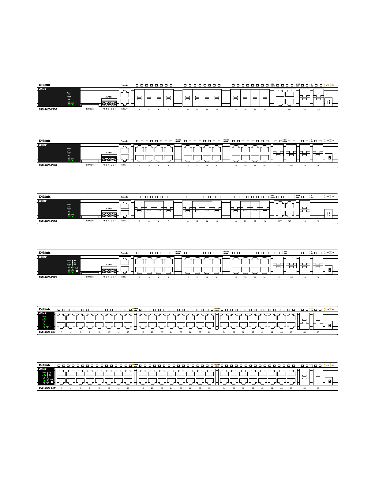
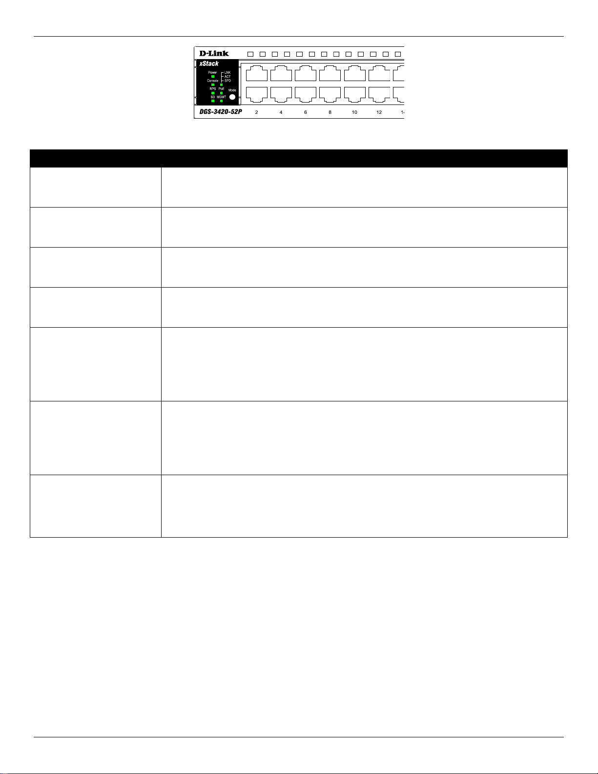
Front-Panel Components
The front panel of the DGS-3420 Series consists of a Management and Console port, LED indicators for Power, Console,
an Alarm Port, and stacking ID LED’s. A separate table below describes LED indicators in more detail.
Figure 1- 1. Front panel view of a DGS-3420-28SCSwitch
Figure 1- 2. Front panel view of a DGS-3420-28TC Switch
Figure 1- 3. Front panel view of a DGS-3420-26SC Switch
Figure 1- 4. Front panel view of a DGS-3420-28PC Switch
Figure 1- 5. Front panel view of a DGS-3420-52T Switch
Figure 1- 6. Front panel view of a DGS-3420-52P Switch
12
Page 14
xStack® DGS-3420 Series Layer 2+ Mana ged St ac k able Gigabit Switch Hardware Installation Reference Guide
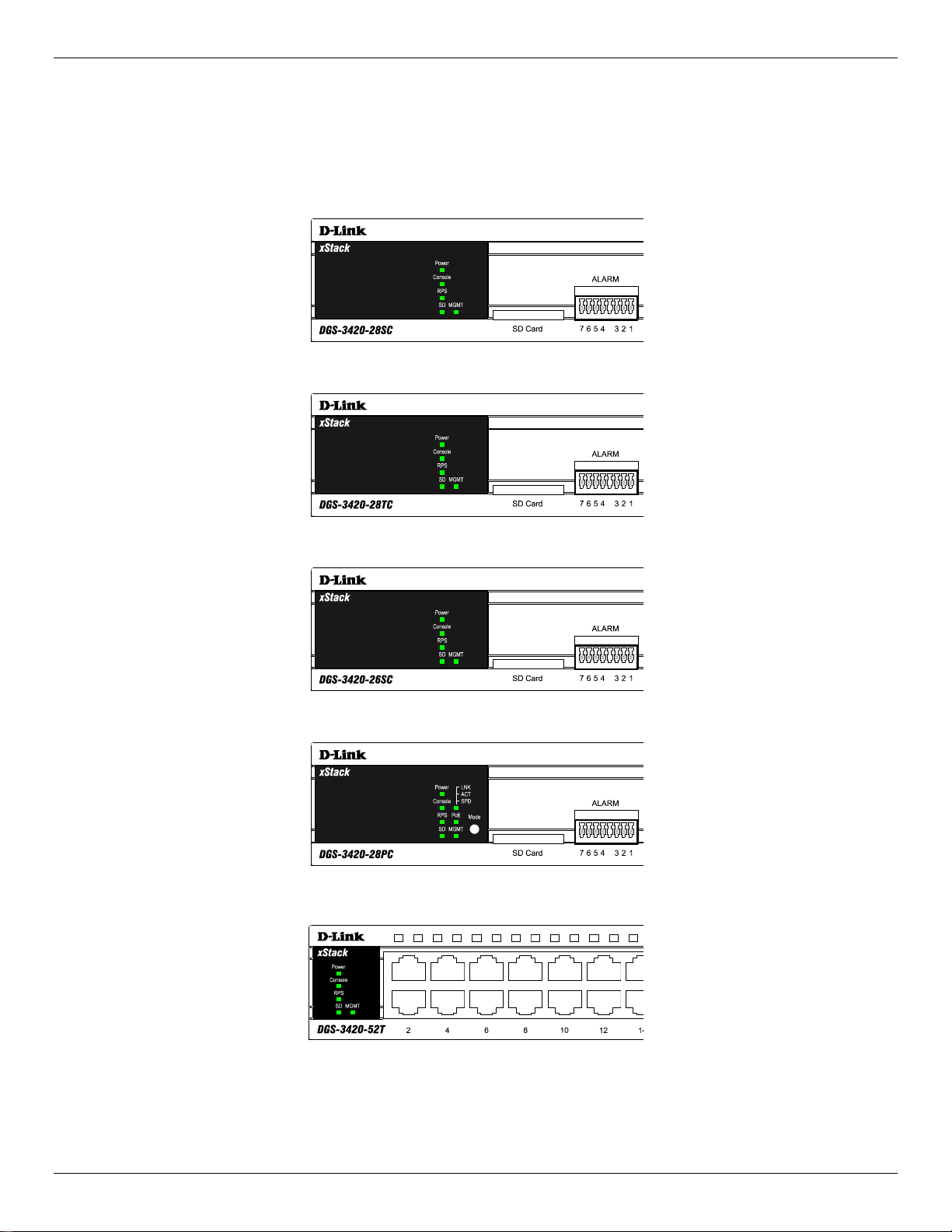
LED Indicators
The Switch front panel presents LED indicators for Power, Console, RPS, Master (stack control), SD, Stack ID and
Link/Act indicators for all ports including the Gigabit Ethernet ports. The DGS-3420-28PC and DGS-3420-52P switches
are equipt with an additional PoE light, to indication whether the ports are running in Power over Ethernet mode.
Figure 1- 7. LED indicators for the DGS-3420-28SC
Figure 1- 8. LED indicators for the DGS-3420-28TC
Figure 1- 9. LED indicators for the DGS-3420-26SC
Figure 1- 10. LED indicators for the DGS-3420-28PC
Figure 1- 11. LED indicators for the DGS-3420-52T
13
Page 15
xStack® DGS-3420 Series Layer 2+ Mana ged St ac k able Gigabit Switch Hardware Installation Reference Guide
Figure 1- 12. LED indicators for the DGS-3420-52P
LED Description
Power
Console
RPS
SD
Stack ID
Link/Act LEDs
This LED will light green after powering the Switch on to indicate the ready state of the
device. The indicator is dark when the Switch is no longer receiving power (i.e. powered
off).
This LED will blink green during the Power-On Self Test (POST). When the POST is
finished, the LED goes dark. The indicator will light steady green when a user is logged in
through the console port.
This LED will light green if the Redundant Powers Supply is in use. If the indicator is off, the
RPS is not in use. When the switch detects that the RPS is connected, the light will be
blinking.
This LED will light green if a Secure Digital (SD) card is plugged in. When the Switch is
reading or writing, the indicator will blink green. No light LED means there is no link. A solid
red LED indicates SD card failure.
For standalone Switches, this will display number “1”. For stacked Switches, this indicates
the position in the stacking box ID. The box ID is assigned either by the user (static mode)
or by the system (automatic mode). When “1” to “12” is displayed, this indicates the
stacking position of the switch. An “H” indicates the device was assigned as the stacking
Master. “h“ means the device was selected to be the Backup Master. A “G” is displayed
when the Safeguard Engine feature enters the exhausted mode.
The Switch has LED indicators for Link and Activity. The LED will light steady green when
there is a secure connection (or link) to a 1000Mbps Ethernet device at any of the ports, or
steady orange when there is a secure connection (or link) to a 10/100Mbps Ethernet device
at any of the ports. The LED will blink green when a 1000Mbps port is active, or blink
orange when a 10/100Mbps port is active. The LED remains dark when there is no link or
activity.
PoE
Only the DGS-3420-28PC and the DGS-3420-52P switches are equipt with a PoE LED.
When this light is on with a solid green light, it means that the corresponding ports are
feeding power to the PoE devices plugged in. When this light is on with a solid orange light,
it means that the port is in an error condition state. When this light is off, it means that the
ports are not supplying power to the devices plugged into the ports.
14
Page 16
xStack® DGS-3420 Series Layer 2+ Mana ged St ac k able Gigabit Switch Hardware Installation Reference Guide
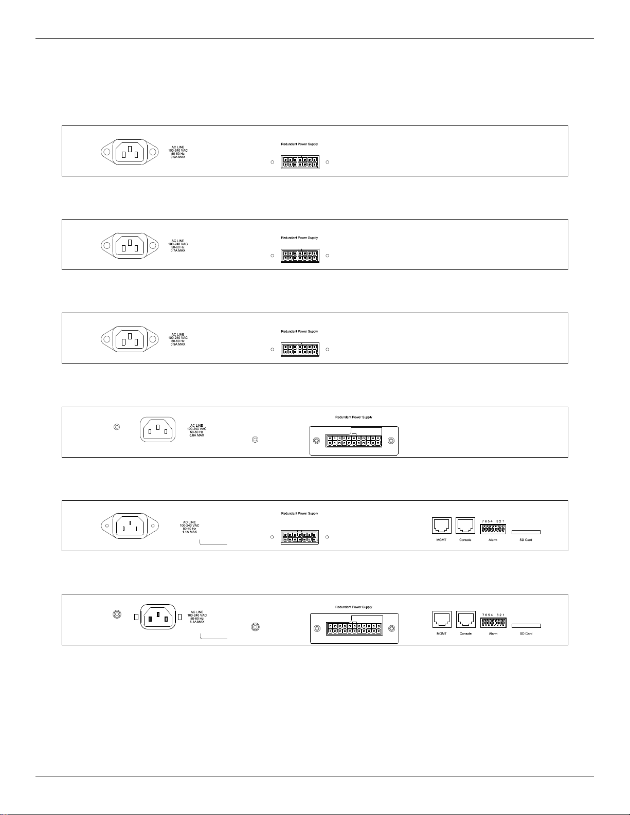
Rear Panel Components
The rear panel contains an AC/DC power connector and an outlet for an external redundant power supply.
Figure 1- 13. Rear panel view of a DGS-3420-28SC Switch
Figure 1- 14. Rear panel view of a DGS-3420-28TC Switch
Figure 1- 15. Rear panel view of a DGS-3420-26SC Switch
Figure 1- 16. Rear panel view of a DGS-3420-28PC Switch
Figure 1- 17. Rear panel view of a DGS-3420-52T Switch
Figure 1- 18. Rear panel view of a DGS-3420-52P Switch
The AC power connector is a standard three-pronged connector that supports the power cord. Plug-in the female
connector of the provided power cord into this socket, and the male side of the cord into a power outlet. The Switch
automatically adjusts the power setting to any supply voltage in the range from 100~240 VAC at 50~60 Hz. An optional
external Redundant Power Supply (DPS-500 for DGS-3420-28TC/28SC/26SC/52T, DPS-700 for DGS-3420-28PC/52P)
can be plugged into the RPS outlet displayed above. When the internal power fails, this optional external RPS will take
over all the power immediately and automatically.
15
Page 17

xStack® DGS-3420 Series Layer 2+ Mana ged St ac k able Gigabit Switch Hardware Installation Reference Guide
Side Panel Components
The system heat vents located on each side dissipate heat. Do not block these openings. Leave at least 6 inches of space
at the rear and sides of the Switch for proper ventilation. Be reminded that without proper heat dissipation and air
circulation, system components might overheat, which could lead to system failure or even severely damage components.
Figure 1- 19. Side panels of the DGS-3420-28SC Switch
Figure 1- 20. Side panels of the DGS-3420-28TC Switch
Figure 1- 21. Side panels of the DGS-3420-26SC Switch
Figure 1- 22. Side panels of the DGS-3420-28PC Switch
16
Page 18

xStack® DGS-3420 Series Layer 2+ Mana ged St ac k able Gigabit Switch Hardware Installation Reference Guide
Figure 1- 23. Side panels of the DGS-3420-52T Switch
Figure 1- 24. Side panels of the DGS-3420-52P Switch
17
Page 19

xStack® DGS-3420 Series Layer 2+ Mana ged St ac k able Gigabit Switch Hardware Installation Reference Guide
Chapter 2 Installation
Package Contents
Installation Guidelines
Power On (AC Power)
Alarm Connector
Installing SFP and SFP+ Ports
Connecting to a Redundant Power Supply
External Redundant Power System
Package Contents
Open the shipping carton of the Switch and carefully unpack its contents. The carton should contain the following items:
• One DGS-3420 Series Switch
• One AC power cord
• One RJ-45 to RS-232 console cable
• One mounting kit (two brackets and screws)
• Four rubber feet with adhesive backing
• One CD kit for CLI reference guide/Web UI reference guide/Hardware Installation Guide/D-View module
If any item is missing or damaged, please contact your local D-Link Reseller for replacement.
Installation Guidelines
Please follow these guidelines for setting up the Switch:
• Install the Switch on a sturdy, level surface that can support at least 6.6 lb. (3kg – This is without PoE
functionality) of weight. Do not place hea vy objects on the Switch.
• The power outlet should be within 1.82 meters (6 feet) of the Switch.
• Visually inspect the power cord and see that it is fully secured to the AC power port.
• Make sure that there is proper heat dissipation from and adequate ventilation around the Switch. Leave at least
10 cm (4 inches) of space at the front and rear of the Switch for ventilation.
• Install the Switch in a fairly cool and dry place for the acceptable temperature and humidity operating ranges.
• Install the Switch in a site free from strong electromagnetic field generators (such as motors), vibration, dust, and
direct exposure to sunlight.
• When installing the Switch on a level surface, attach the rubber feet to the bottom of the device. The rubber feet
cushion the Switch, protect the casing from scratches and prevent it from scratching other surfaces.
18
Page 20

xStack® DGS-3420 Series Layer 2+ Mana ged St ac k able Gigabit Switch Hardware Installation Reference Guide
Installing the Switch without a Rack
First, attach the rubber feet included with the Switch if installing on a desktop or shelf. Attach these cushioning feet on the
bottom at each corner of the device. Allow enough ventilation space between the Switch and any other objects in the
vicinity.
Figure 2–1 Attach rubber feet to the switch.
Attaching Brackets to a Switch for Rack Mounting
The Switch is mounted to a standard 19" rack using mounting brackets. Use the following diagrams as a guide.
Figure 2–2 Attach mounting brackets to the switch
Fasten the mounting brackets to the Switch using the screws provided. With the brackets attached securely, the Switch
can be mounted in a standard rack, as shown below.
NOTE: Please review the Installation Guidelines above before installing the Switch in a rack. Make
sure there is adequate space around the Switch to allow for proper air flow, ventilation and cooling.
19
Page 21

xStack® DGS-3420 Series Layer 2+ Mana ged St ac k able Gigabit Switch Hardware Installation Reference Guide
Mounting the Switch in a Standard 19" Rack
Figure 2–3 Mount the switch in a rack
Power On (AC Power)
1. Plug one end of the AC power cord into the power connector of the Switch and the other end into the local power
source outlet.
2. Once the system is powered on, the LED’s blink green to indicate that the system is resetting.
Power Failure (AC Power)
In the event of a power failure, just as a precaution, unplug the Switch. After the power returns, plug the switch back in to
the power socket.
CAUTION: Installing systems in a rack without the front and side stabilizers installed could cause the rack
to tip over, potentially resulting in bodily injury under certain circumstances. Therefore, always install the
stabilizers before installing components in the rack. After installing components in a rack, do not pull more
than one component out of the rack on its slide assemblies at one time. The weight of more than one
extended component could cause the rack to tip over and may result in injury.
Alarm Connector
The alarm connector can be used to use external devices when triggered events occur.
20
Page 22

xStack® DGS-3420 Series Layer 2+ Mana ged St ac k able Gigabit Switch Hardware Installation Reference Guide
Figure 2–4 Alarm Connector
Alarm Connector Port
Contact Description
1
2
3
4
5
6
7
Output. Normal Closed Pin. (42VAC or 60VDC)
Output. Common Pin. (42VAC or 60VDC)
Output. Normal Open Pin. (42VAC or 60VDC)
Input 2
Input 2
Input 1
Input 1
Connect the alarm input pins to alarm output terminals on other pieces of equipment.
Connect the alarm output pins to alarm input terminals on other pieces of equipment.
21
Page 23

xStack® DGS-3420 Series Layer 2+ Mana ged St ac k able Gigabit Switch Hardware Installation Reference Guide
Installing SFP and SFP+ Ports
The Switch is equipped with SFP (Small Form Factor Portable) and SFP+ ports, which are used with fiber-optical
transceiver cabling.SFP ports support full-duplex transmissions, auto-negotiation, and can be uplinked with various other
switches across a gigabit network. The SFP ports support data rates of up to 1Gbit/s and the SFP+ ports support data
rates of up to 10Gbit/s.
See the figure below for installing the SFP ports in the Switch.
Figure 2–5 Inserting fiber-optic transceivers into a DGS-3420 Series Switch
For a full list of supported transceivers compatible with this switch series, refer to Port Functions on page 43
.
22
Page 24

xStack® DGS-3420 Series Layer 2+ Mana ged St ac k able Gigabit Switch Hardware Installation Reference Guide
Connecting to a Redundant Power Supply
The Switch connects to the Master Switch using a 14-pin DC power cable. A standard, three-pronged AC power cable
connects the redundant power supply to the main power source.
Figure 2–6 Connecting a DGS-3420 Series Switch to the DPS-500 (28TC, 28SC, 26SC, and 52T)
1. Insert one end of the 14-pin DC power cable into the port on the switch and the other end into the redundant
power supply.
2. Using a standard AC power cable, connect the redundant power supply to the main AC power source. A green
LED on the front of the DPS-500 will glow to indicate a successful connection.
3. Re-connect the switch to the AC power source. The LED indicator will show that a redundant power supply is now
in operation.
4. Do not make any changes on the switch.
NOTE: See the DPS-500 documentation for more information.
CAUTION: Only the DGS-3420-28TC, DGS-3420-28SC, DGS-3420-26SC, and the DGS-3420-52T
use the DPS-500. The DGS-3420-28PC and the DGS-3420-52P use the DPS-700.
23
Page 25

xStack® DGS-3420 Series Layer 2+ Mana ged St ac k able Gigabit Switch Hardware Installation Reference Guide
External Redundant Power System
The DPS-500/700 is a redundant power-supply unit designed to conform to the voltage requirements of the switches
being supported. The DPS-500/700 can be installed into a DPS-900, or DPS-800 rack mount unit.
CAUTION: DO NOT connect the RPS to AC power before the DC power cable is connected. This might
damage the internal power supply.
DPS-900
The DPS-900 is a standard-size rack mount (5 standard units in height) designed to hold up to eight DPS-500 redundant
power supplies. However, it cannot hold eight DGS-700 modules.
Figure 2–7 Inserting the DPS-500 into the DPS-900
The RPS can be mounted in a standard 19" rack. Use the following diagram to guide you.
24
Page 26

xStack® DGS-3420 Series Layer 2+ Mana ged St ac k able Gigabit Switch Hardware Installation Reference Guide
Figure 2–8 Install the DPS-900 into the equipment rack
CAUTION: Installing systems in a rack without the front and side stabilizers installed could cause the
rack to tip over, potentially resulting in bodily injury under certain circumstances. Therefore, always
install the stabilizers before installing components in the rack. After installing components in a rack, do
not pull more than one component out of the rack on its slide assembly at a time. The weight of more
than one extended component could cause the rack to tip over and may result in injury.
DPS-800
The DPS-800 is a standard-size rack mount (1 standard unit in height) designed to hold up to two DPS-200, DPS-300 and
DPS-500 redundant power supplies.
25
Page 27

xStack® DGS-3420 Series Layer 2+ Mana ged St ac k able Gigabit Switch Hardware Installation Reference Guide
Figure 2–9 Install the DPS-500 in the DPS-800
The RPS can be mounted in a standard 19" rack. Use the following diagram to guide you.
Figure 2–10 Install the DPS-800 in an Equipment Rack
26
Page 28

xStack® DGS-3420 Series Layer 2+ Mana ged St ac k able Gigabit Switch Hardware Installation Reference Guide
Chapter 3 Connecting the Switch
Switch to End Node
Switch to Switch
Connecting To Network Backbone or Server
Switch to End Node
End nodes include PCs outfitted with a 10/100/1000Mbps RJ-45 Ethernet Network Interface Card (NIC) and routers. An
end node connects to the Switch via a twisted-pair UTP/STP cable. Connect the end node to any of the 1000BASE-T
ports of the Switch. The Link/Act LEDs for each Ethernet port turns green or amber when the link is active. A blinking LED
indicates packet activity on that port.
Figure 3–1 Connect a DGS-3420 Series Switch to an end node
NOTE: All high-performance N-Way Ethernet ports can support both MDI-II and MDI-X connections.
Switch to Switch
There is a great deal of flexibility on how connections are made using the appropriate cabling.
• Connect a 10BASE-T switch port to the Switch via a twisted-pair Category 3, 4 or 5 UTP/STP cable.
• Connect a 100BASE-TX switch port to the Switch via a twisted-pair Category 5 UTP/STP cable.
• Connect 1000BASE-T switch port to the Switch via a twisted pair Category 5e UTP/STP cable.
• Connect switch supporting a fiber-optic uplink to the Switch’s SFP ports via fiber-optic cabling. See cabling
guidelines in Appendix B for more information.
27
Page 29

xStack® DGS-3420 Series Layer 2+ Mana ged St ac k able Gigabit Switch Hardware Installation Reference Guide
Figure 3–2 Connect the Switch to a port on a switch with a straight or crossover cable
Connect to a Network Backbone or Server
The combo SFP ports and the 1000BASE-T ports are ideal for uplinking to a network backbone, server or server farm.
The copper ports operate at a speed of 10/100/1000Mbps in half or full duplex mode. The fiber-optic ports can operate at
both 100Mbps and 1000Mbps in full duplex mode.
You can connect to the Gigabit Ethernet ports using a fiber-optic cable or a Category 5E copper cable, depending on the
type of port. The Link LED turns green when a connection is made.
Figure 3–3 Connect a DGS-3420 Series Switch to a server
28
Page 30

xStack® DGS-3420 Series Layer 2+ Mana ged St ac k able Gigabit Switch Hardware Installation Reference Guide
Chapter 4 Introduction to Switch Management
Management Options
Connecting the Console Port
Connecting to the Switch for the first time
Connecting to the Management Port
Password Protection
Assigning IP Addresses
SNMP Settings
Management Options
This system may be managed out-of-band through the console port on the front panel or in-band using Telnet. The user
may also choose the web-based management, accessible through a web browser.
Web-based Management Interface
After successfully installing the Switch, the user can configure the Switch, monitor the LED panel, and display statistics
graphically using a Web browser, such as Microsoft® Internet Explorer (version 5.5 and later), Netscape (version 8 and
later), Mozilla Firefox (version 2.0 and later), Safari (version 4.0 and later), and Google Chrome (version 6.0 and later).
SNMP-Based Management
The Switch is also managed with an SNMP-compatible console program. It supports SNMP version 1.0, 2.0 and 3.0. The
SNMP agent decodes the incoming SNMP messages and responds to requests with MIB objects stored in the database.
The SNMP agent updates the MIB objects to generate statistics and counters.
Command Line Interface Management through the Serial Port or remote Telnet
The user can also connect a computer or terminal to the serial console port to access the DGS-3420 range. The
command line interface provides complete access to all DGS-3420 Series of switches management features.
Connecting the Console Port
The console port on the front panel of the Switch is used to connect a computer that monitors and configures the switch.
The console port is an RJ-45 port and requires a special cable that is included with the switch, to establish the physical
connection.
To use the console port, the following equipment is needed:
• A terminal or a computer with both an RS-232 serial port and the ability to emulate a terminal.
• A console cable with a male DB-9 connector on one end and an RJ-45 connection on the other. This cable should
be included with any of the DGS-3420 Series. It establishes the physical connection to the console port.
To connect a terminal to the console port:
Connect the male DB-9 connector on the console cable (shipped with the DGS-3420-28SC for example) to the RS-232
serial port on the computer running terminal emulation software then insert the RJ-45 connector into the RJ-45 console
port on the front of the switch. Set the terminal emulation software as follows:
• Select the appropriate serial port (COM port 1 or COM port 2).
• Set the data rate to 115200 baud.
• Set the data format to 8 data bits, 1 stop bit, and no parity.
• Set flow control to None.
• Under Properties, select VT100 for Emulation mode.
29
Page 31

xStack® DGS-3420 Series Layer 2+ Mana ged St ac k able Gigabit Switch Hardware Installation Reference Guide
• Select Terminal keys for Function, Arrow and Ctrl keys. Make sure to use Terminal keys (not Windows keys) are
selected.
NOTE: When using HyperTerminal with the Microsoft® Windows® 2000 operating system, ensure that
Windows 2000 Service Pack 2 or later is installed. Windows 2000 Service Pack 2 allows the use of arrow
keys in HyperTerminal's VT100 emulation. See www.microsoft.com for information on Windows 2000
service packs.
• After you have correctly set up the terminal, plug the power cable into the power socket on the back of the DGS-
3420 Series switch. The boot sequence appears in the terminal.
• After the boot sequence completes, the console login screen displays.
• If the user has not logged into the command line interface (CLI) program, press the Enter key at the User name
and password prompts. There is no default user name and password for the Switch. The administrator must first
create user names and passwords. If user accounts have been previously set up, log in and continue to configure
the Switch.
• Enter the commands to complete desired tasks. Many commands require administrator-level access privileges.
Read the next section for more information on setting up user accounts. See the DGS-3420 Series CLI
Reference Guide on the documentation CD for a list of all commands and additional information on using the
CLI.
• To end a management session, use the logout command or close the emulator program.
If you experience problems while making a connection, make sure the emulation is set to VT-100. The emulation settings
can be configured by:
1. Click File Menu in HyperTerminal
2. Click Properties from the drop-down menu
3. Click the Settings Tab
This is where you will find the Emulation options. If you still do not see anything, try rebooting the Switch by disconnecting
its power supply.
Once connected to the console, the following image appears. This is where the user will enter commands to perform all
the available management functions. The Switch will prompt the user to enter a user name and password. Logg ing on at
the beginning requires no username or password. Just press the Enter key twice to access the command line interface.
Boot Procedure V1.00.003
-------------------------------------------------------------------------------
Power On Self Test ........................................ 100 %
MAC Address : 00-01-02-03-04-00
H/W Version : B1
Please Wait, Loading V1.50.010 Runtime Image .............. 100 %
UART init ................................................. 100 %
Starting runtime image
Device Discovery .......................................... 100 %
Configuration init ........................................ 100 %
Figure 4–1 Boot up display in console screen
30
Page 32

xStack® DGS-3420 Series Layer 2+ Mana ged St ac k able Gigabit Switch Hardware Installation Reference Guide
UserName:
Connecting to the Switch for the first time
The Switch supports user-based security that prevents unauthorized users from accessing the switch or changing its
settings. This section explains how to log into the DGS-3420 Se ries Switch from an out-of-band Management port
connection.
Once you have connected to the Switch, the following screen appears:
DGS-3420-28SC Gigabit Ethernet Switch
Command Line Interface
Firmware: Build 1.50.010
Copyright(C) 2013 D-Link Corporation. All rights reserved.
Figure 4–2 Initial screen, first time connecting to the Switch
Press Enter in both the Username and Password fields. Then access will be given to enter commands after the command
prompt DGS-3420-28SC:admin#
There is no initial username or password. Leave the Username and Password fields blank.
NOTE: The first user automatically gets Administrator level privileges. At least one Admin-level user
account must be created for the Switch.
Connecting to the Management Port
The front panel of the Switch features an out-of-band RJ-45 Management port which can easily connect to a notebook.
Connect to the out-of-bound management console using a web browser or Telnet command prompt interface. This is the
default login interface, and is the tool you can use when connecting to the Switch for the first time.
To use the Management port, connect one end of an Ethernet cable to a computer and the other to the switch. The default
IP address of the Management port is 192.168.0.1, and a subnet mask of 255.255.255.0. Make sure that the computer
being used for Switch management has a nonconflicting IP address in the 192.168.0.x subnet.
The IP settings or enabled status of the Management port can be changed through the console port, or through the webbased Switch management interface. To change the configuration of the Management port, use the command:
config out_band_ipif {ipaddress <network_address> | state [enable | disable] | gateway <ipaddr>}
To view the status or IP settings, use the command:
show out_band_ipif
To change settings for the out-of-band Management port in the web interface, use the following path:
Management > Out of Band Management Settings
31
Page 33

xStack® DGS-3420 Series Layer 2+ Mana ged St ac k able Gigabit Switch Hardware Installation Reference Guide
DGS-3420-28SC:admin#
Password Protection
The DGS-3420 Series Switches do not have a default user name and password. One of the first tasks when settings up
the Switch is to create user accounts. Logging in using a predefined administrator-level user name will give the user
privileged access to the Switch's management software.
After the initial login, define new passwords for both default user names to prevent unauthorized access to the Switch,
and record the passwords for future reference.
To create an administrator-level account for the Switch, do the following:
1. At the CLI login prompt, enter create account admin followed by the <username> and press the Enter key.
2. The Switch will then prompt the user to provide a password. Type the administrator <password>and press the
Enter key.
3. Once entered, the Switch will again ask the user to insert the same password again to verify it. Type the same
password and press the Enter key.
4. A new administrative account is created once the “Success” prompt appears.
NOTE: Passwords are case sensitive. User names and passwords can be up to 15 characters in length.
The sample below illustrates a successful creation of a new administrator-le v el acc ount with the us er nam e
"newmanager".
DGS-3420-28SC:admin# create account admin newmanager
Command: create account admin newmanager
Enter a case-sensitive new password:*********
Enter the new password again for confirmation:*********
Success.
Figure 4–3 Create account command
NOTICE: CLI configuration commands only modify the running configuration file and are not saved
when the Switch is rebooted. To save all your configuration changes in nonvolatile storage, you must
use the save command to copy the running configuration file to the startup configuration.
Assigning IP Addresses
Each Switch must be assigned its own IP Address, which is used for communication with an SNMP network manager or
other TCP/IP application (for example BOOTP, TFTP). The Switch's default IP address is 10.90.90.90. You can change
the default Switch IP address to meet the specification of your networking address scheme.
The Switch is also assigned a unique MAC address by the factory. This MAC address cannot be changed, and can be
found by entering the command
show switch into the command line interface, as shown below.
32
Page 34

xStack® DGS-3420 Series Layer 2+ Mana ged St ac k able Gigabit Switch Hardware Installation Reference Guide
CTRL+C ESC q Quit SPACE n Next Page ENTER Next Entry a All
DGS-3420-28SC:admin#show switch
Command: show switch
Device Type : DGS-3420-28SC Gigabit Ethernet Switch
MAC Address : 00-01-02-03-04-00
IP Address : 10.90.90.90 (Manual)
VLAN Name : default
Subnet Mask : 255.0.0.0
Default Gateway : 0.0.0.0
Boot PROM Version : Build 1.00.003
Firmware Version : Build 1.50.010
Hardware Version : B1
System Name :
System Location :
System Uptime : 0 days, 0 hours, 21 minutes, 21 seconds
System Contact :
Spanning Tree : Disabled
GVRP : Disabled
IGMP Snooping : Disabled
MLD Snooping : Disabled
RIP : Disabled
RIPng : Disabled
VLAN Trunk : Disabled
Telnet : Enabled (TCP 23)
Web : Enabled (TCP 80)
Figure 4–4 Show switch command
The Switch's MAC address can also be found from the Web management program on the System Information window
in the Configuration folder.
The IP address for the Switch must be set before it can be managed with the Web-based manager. The Switch IP
address can be automatically set using BOOTP or DHCP protocols, in which case the actual address assigned to the
Switch must be known.
The IP address may be set using the Command Line Interface (CLI) over the console serial port as follows:
Starting at the command line prompt, enter the commands
config ipif System ipaddress xxx.xxx.xxx.xxx/yyy.yyy.yyy.yyy
Where the x's represent the IP address to be assigned to the IP interface named System and the y's represent the
corresponding subnet mask.
Alternatively, you can enter
config ipif System ipaddress xxx.xxx.xxx.xxx/z. Where the x's represent the IP
address to be assigned to the IP interface named System and the z represents the corresponding number of subnets in
CIDR notation.
The IP interface named System on the Switch can be assigned an IP address and subnet mask, and then be used to
connect a management station to the Switch's Telnet or Web-based management agent.
33
Page 35

xStack® DGS-3420 Series Layer 2+ Mana ged St ac k able Gigabit Switch Hardware Installation Reference Guide
DGS-3420-28SC:admin#
DGS-3420-28SC:admin# config ipif System ipaddress 10.90.90.91/255.0.0.0
Command: config ipif System ipaddress 10.90.90.91/8
Success.
Figure 4–5 Assigning the Switch an IP Address
In the above example, the Switch was assigned an IP address of 10.90.90.91 with a subnet mask of 255.0.0.0. (the CIDR
form was used to set the address (10.90.90.91/8). The system message Success indicates that the command was
executed successfully. The Switch can now be configured and managed via Telnet and the CLI or via the Web-based
management.
SNMP Settings
Simple Network Management Protocol (SNMP) is an OSI Layer 7 (Application Layer) designed specifically for managing
and monitoring network devices. SNMP enables network management stations to read and modify the settings of
gateways, routers, switches and other network devices. Use SNMP to configure system features for proper operation,
monitor performance and detect potential problems in the Switch, switch group or network.
Managed devices that support SNMP include software (referred to as an agent), which runs locally on the device. A
defined set of variables (managed objects) is maintained by the SNMP agent and used to manage the device. These
objects are defined in a Management Information Base (MIB), which provides a standard presentation of the information
controlled by the on-b oar d SNMP agent. SNMP defines both the format of the MIB specifications and the protocol used to
access this information over the network.
The Switch supports SNMP versions 1, 2c, and 3. The administrator may specify which SNMP version to use to monitor
and control the Switch. The three SNMP versions vary in the level of security provided between the management station
and the network device.
In SNMP v1 and v2, user authentication is accomplished using 'community strings', which function like passwords. The
remote user SNMP application and the Switch SNMP must use the same community string. SNMP packets from any
station that has not been authenticated are ignored (dropped).
The default community strings for the Switch used for SNMP v1 and v2 management access are:
• public - Allows authorized management stations to retrieve MIB objects.
• private - Allows authorized management stations to retrieve and modify MIB objects.
SNMP v3 uses a more sophisticated authentication process that is separated into two parts. The first part is to maintain a
list of users and their attributes that are allowed to act as SNMP managers. The second part describes what each user on
that list can do as an SNMP manager.
The Switch allows groups of users to be listed and configured with a shared set of privileges. The SNMP version may also
be set for a listed group of SNMP managers. Thus, a group of SNMP managers can be created to view read-only
information or receive traps using SNMP v1 while assigning a higher level of security to another group, granting read/write
privileges using SNMP v3.
Using SNMP v3 individual users or groups of SNMP managers can be allowed to perform or be restricted from performing
specific SNMP management functions. The functions allowed or restricted are defined using the Object Identifier (OID)
associated with a specific MIB. An additional layer of security is available for SNMP v3 in that SNMP messages may be
encrypted. To read more about how to configure SNMP v3 settings for the Switch read the section entitled Managem ent.
34
Page 36

xStack® DGS-3420 Series Layer 2+ Mana ged St ac k able Gigabit Switch Hardware Installation Reference Guide
Traps
Traps are messages that alert network personnel of events that occur on the Switch. The events can be as serious as a
reboot (someone accidentally turned OFF the Switch), or less serious like a port status change. The Switch generates
traps and sends them to the trap recipient (or network manager). Typical traps include trap messages for Authentication
Failure, Topology Change and Broadcast\Multicast Storm.
Management Information Base (MIB)
The Switch in the Management Information Base (MIB) stores management and counter information. The Switch uses the
standard MIB-II Management Information Base module. Consequently, values for MIB objects can be retrieved from any
SNMP-based network management software. In addition to the standard MIB-II, the Switch also supports its own
proprietary enterprise MIB as an extended Management Information Base. The proprietary MIB may also be retrieved by
specifying the MIB Object Identifier. MIB values can be either read-only or read-write.
35
Page 37

xStack® DGS-3420 Series Layer 2+ Mana ged St ac k able Gigabit Switch Hardware Installation Reference Guide
Chapter 5 Web-based Switch Configuration
Introduction
Logging onto the Web Manager
Web-based User Interface
Web Pages
Introduction
Most software functions of the Switch can be managed, configured, and monitored via the embedded Web-based (HTML)
interface. Manage the Switch from remote stations anywhere on the network through a standard browser, such as Internet
Explorer (version 5.5 and later), Netscape (version 8.0 and later), Mozilla Firefox (version 2.0 and later), or Safari (version
4.0 and later). The browser acts as a universal access tool and can communicate directly with the Switch using the HTTP
protocol.
Logging onto the Web Manager
To begin managing the Switch, simply run the browser installed on your computer and point it to the IP address you have
defined for the device. The URL in the address bar should read something like: http://123.123.123.123, where the
numbers 123 represent the IP address of the Switch.
NOTE: The factory default IP address, for a normal port, is 10.90.90.90. The factory default IP address, for
the management port, is 192.168.0.1.
The Web User Interface’s authentication wind o w can b e accessed using the IP address of 10.90.90.90 (normal port), as
seen below.
Figure 5–1 Enter Network Password Window
Leave the User Name field and the Pas s word field blank and click OK. This will open the Web-based user interface. The
Switch management features available in the web-based manager are explained below.
36
Page 38

xStack® DGS-3420 Series Layer 2+ Mana ged St ac k able Gigabit Switch Hardware Installation Reference Guide
Web-based User Interface
The user interface provides access to various Switch configuration and management windows, it allows the user to view
performance statistics, and permits graphical monitoring of the system status.
Areas of the User Interface
The figure below shows the user interface. Three distinct areas divide the user interface, as described in the table.
AREA 2
AREA 1
Area Function
Area 1
Area 2
Area 3
Select the folder or window to display. Open folders and click the hyperlinked window
buttons and subfolders contained within them to display windows.
Presents a graphical near real-time image of the front panel of the Switch. This area
displays the Switch's ports and expansion modules and shows port activity, depending on
the specified mode. Some management functions, including port monitoring are accessible
here. Click the D-Link logo to go to the D-Link Website.
Presents Switch status based on user selection and the entry of configuration data. In
addition, hyperlinks are offered for many Switch features to enable quick configuration.
AREA 3
Figure 5–2 Main Web-manager Window
Web Pages
When connecting to the management mode of the Switch with a Web browser, a login screen is displayed. Enter a user
name and password to access the Switch's management mode.
Below is a list of the main folders available in the Web interface:
37
Page 39

xStack® DGS-3420 Series Layer 2+ Mana ged St ac k able Gigabit Switch Hardware Installation Reference Guide
• System Configuration - In this section the user will be able to configure features regarding the Switch’s
configuration.
• Management - In this section the user will be able to configure features regarding the Switch’s management.
• L2 Features - In this section the user will be able to configure features regarding the Layer 2 functionality of the
Switch.
• L3 Features - In this section the user will be able to configure features regarding the Layer 3 functionality of the
Switch.
• QoS - In this section the user will be able to configure features regarding the Quality of Service functionality of the
Switch.
• ACL - In this section the user will be able to configure features regarding the Access Control List functionality of
the Switch.
• Security - In this section the user will be able to configure features regarding the Switch’s security.
• Network Application - In this section the user will be able to configure features regarding network applications
handled by the Switch.
• OAM - In this section the user will be able to configure features regarding the Switch’s operations, administration
and maintenance (OAM).
• Monitoring - In this section the user will be able to monitor the Switch’s configuration and statistics.
38
Page 40

xStack® DGS-3420 Series Layer 2+ Mana ged St ac k able Gigabit Switch Hardware Installation Reference Guide
Appendix Section
Appendix A – Technical Specifications
General
Feature Detailed Description
Standards
Protocols
Data Transfer Rates:
Ethernet
Fast Ethernet
Gigabit Ethernet
10 Gigabit Ethernet
Stacking Topology
Network Cables
IEEE 802.3 compliance
IEEE 802.3u compliance
Support Full-Duplex operations
IEEE 802.3az compliance (Hardware Version :B1)
IEEE 802.3x Flow Control support for Full-Duplex mode
IEEE 802.3ab compliance
IEEE 802.3af compliance (DGS-3420-28 PC & DGS-3420-52P only)
IEEE 802.3at compliance (DGS-3420-28 PC & DGS-3420-52P only)
IEEE 802.3z compliance
IEEE 802.3ae compliance
IEEE 802.3aq compliance
IEEE 1588
CSMA/CD
Half-duplex Full-duplex
10 Mbps 20Mbps
100Mbps 200Mbps
------------- 2Gbps
------------- 20Gbps
Duplex Ring, Duplex Chain
Cat.5 Enhanced for 1000BASE-T
UTP Cat.5, Cat. 5 Enhanced for 100BASE-TX
UTP Cat.3, 4, 5 for 10BASE-T
EIA/TIA-568 100-ohm screened twisted-pair (STP)(100m)
Physical and Environmental
Feature Detailed Description
Internal Power Supply AC Input: 100~240VAC, 50~60Hz
Optional Redundant
Power Supply
Fans
Power Consumption
One connector in back to install optional external RPS. When internal power fails, the
optional external RPS will take over all the power supply immediately and automatically.
DPS-500: DGS-3420-28SC/28TC/26SC/52T
DPS-700: DGS-3420-28PC/52P
The IC Sensor detects the temperature on the switch automatically, and adjusts the speed.
For hardware version A1/A2, the following applies:
DGS-3420-28SC: 60.3 Watts (Max.)
DGS-3420-28TC: 50.8 Watts (Max.)
39
Page 41

xStack® DGS-3420 Series Layer 2+ Mana ged St ac k able Gigabit Switch Hardware Installation Reference Guide
DGS-3420-26SC: 60.3 Watts (Max.)
DGS-3420-28PC: 478 Watts (Max.) with 350 Watts PoE load.
DGS-3420-52T: 81.0 Watts (Max.)
DGS-3420-52P: 505.4 Watts (Max.) with 350 Watts PoE load
For hardware version B1, the following applies:
DGS-3420-28SC: 42.6 Watts (Max.)
DGS-3420-28TC: 44.9 Watts (Max.)
DGS-3420-26SC: 40.2 Watts (Max.)
DGS-3420-28PC: 502.2 Watts (Max.) with 370 Watts PoE load
DGS-3420-52T: 76 Watts (Max.)
DGS-3420-52P: 517.1 Watts (Max.) with 370 Watts PoE load
Operating Temperature
Storage Temperature
Humidity
Dimensions
Weight
EMI
Safety
0~50°C
-40~70°C
Storage: 5-90% non-condensing
Operation: 10-90% non-condensing
DGS-3420-28SC: 441mm (W) x 310mm (D) x 44mm (H)
DGS-3420-28TC: 441mm (W) x 310mm (D) x 44mm (H)
DGS-3420-26SC: 441mm (W) x 310mm (D) x 44mm (H)
DGS-3420-28PC: 441mm (W) x 380mm (D) x 44mm (H)
DGS-3420-52T: 441mm (W) x 380mm (D) x 44mm (H)
DGS-3420-52P: 441mm (W) x 380mm (D) x 44mm (H)
DGS-3420-28SC: 4.06kg
DGS-3420-28TC: 4.12kg
DGS-3420-26SC: 4.04kg
DGS-3420-28PC: 5.75kg
DGS-3420-52T: 5.07kg
DGS-3420-52P: 6.24kg
CE Class A, FCC Class A , VCCI Class A, C-Tick Report
UL, CB Report
Performance
Feature Detailed Description
Transmission Method
Packet Buffer
Packet Filtering /
Forwarding Rate
Wire speed
Switching Capacity
Store-and-forward
2Mbytes per device
Full-wire speed for all connections
1,488,095 pps per port (for 1000Mbps)
148,810 pps per port (100Mbps)
Wire speed operation on all FE/GE ports
DGS-3420-28SC: 128Gbps
DGS-3420-28TC: 128Gbps
DGS-3420-26SC: 88Gbps
DGS-3420-28PC: 128Gbps
40
Page 42

xStack® DGS-3420 Series Layer 2+ Mana ged St ac k able Gigabit Switch Hardware Installation Reference Guide
DGS-3420-52T: 176Gbps
DGS-3420-52P: 176Gbps
Maximum Forwarding
Rate
Priority Queues
MAC Address Table
Virtual Stacking /
Clustering
DGS-3420-28SC: 95.24 million packets per second.
DGS-3420-28TC: 95.24 million packets per second.
DGS-3420-26SC: 66.47 million packets per second.
DGS-3420-28PC: 95.24 million packets per second.
DGS-3420-52T: 130.95 million packets per second.
DGS-3420-52P: 130.95 million packets per second.
8 Priority Queues per port
Supports 16K MAC address
Supports 256 static MAC
• Support D-Link Single IP Management v1.6
• Manage up to 32 devices in a virtual stack with a single IP address.
LED Indicators
Location LED Indicative Color Status Description
Per Device Power
Green Solid Light Power on
Light off Power off
Console
RPS
SD
MGMT
Stacking ID
Green Solid Light Console on
Light off Console off
Green Blinking When switch detects that RPS is
connected
Solid Light RPS in using
Light off RPS off
Green Solid Light Plugged in
Blinking Busy Reading and Writing
Light off No link
Red Solid Light Read/Write Failed
Green Solid Light Console on
Blinking Secure connection established
Light off Console off
Green Capable 1 – 12, H,
h, G
The box ID is assigned either by user
(static mode) or by the system
(automatic mode). When the box
become a primary master, the 7
segment works as bi-function. That is
box ID and “H” indicate as primary
Master and the display will be shown
by turn. That is boxID -> H -> boxID ->
H
1-12: To indicate the stacking of the
switch
H: When device was assigned as the
stacking Master
41
Page 43

xStack® DGS-3420 Series Layer 2+ Mana ged St ac k able Gigabit Switch Hardware Installation Reference Guide
h: When device was selected to be the
link) to 1000Mbps Ethernet device at
Backup Master
G: When Safeguard Engine entering
the exhausted mode.
LED Per
10/100/1000 Mbps
Port
Port LED Mode
Indicator
Link/Act/Speed Mode
A LED Mode Select Button to switch two modes in turn for all
10/100/1000Mbps ports on DGS-3420-28PC/52P:
- Link/Act/Speed Mode
- PoE Mode
Green Solid Light A LED Mode Select Button to switch
Link/Act/Speed Mode
Solid Light A LED Mode Select Button to switch
PoE Mode
Green Solid Light When there is a secure connection (or
link) to 1000Mbps Ethernet device at
any of the ports.
Blinking When there is reception or
transmission of data occurring at
1000Mbps.
Orange Solid Light When there is a secure connection (or
link) to 10/100Mbps Ethernet device at
any of the ports.
Blinking When there is reception or
transmission of data occurring at
10/100Mbps.
Off Light off No link.
PoE Mode
LED per SFP Port Link/Act
LED per SFP+
Port
Link/Act
Green Solid Light Power feeding.
Orange Solid Light Error Condition.
Off Light Off No Power feeding.
Green Solid Light When there is a secure connection (or
link) to 1000Mbps Ethernet device at
any of the ports.
Blinking When there is reception or
transmission of data occurring at
1000Mbps.
Orange Solid Light When there is a secure connection (or
link) to 100Mbps Ethernet device at
any of the ports.
Blinking When there is reception or
transmission of data occurring at
100Mbps.
Off Light off No link
Green Solid Light When there is a secure connection (or
link) to 10G bps Ethernet device at any
of the ports.
Blinking When there is reception or
transmission (i.e. Activity--Act) of data
occurring at a 10G bps port.
Orange Solid Light When there is a secure connection (or
42
Page 44

xStack® DGS-3420 Series Layer 2+ Mana ged St ac k able Gigabit Switch Hardware Installation Reference Guide
any of the ports.
Blinking When there is reception or
transmission (i.e. Activity--Act) of data
occurring at a 1000Mbps port.
Off Light off Link down
Port Functions
Feature Detailed Description
Console Port
1G Port
RJ-45 interface for out-of-band CLI configuration
10/100/1000BASE-T ports compliant to following standards:
• IEEE 802.3 compliance
• IEEE 802.3u compliance
100/1000BASE-T ports compliant to following standards:
• IEEE 802.3az compliance (Hardware Version :B1)
Support Full-Duplex operations
• IEEE 802.3x Flow Control support for Full-Duplex mode
• IEEE 802.3ab compliance
• IEEE 802.3af compliance (DGS-3420-28 PC & DGS-3420-52P only)
• IEEE 802.3at compliance (DGS-3420-28 PC & DGS-3420-52P only)
SFP ports compliant to following standards:
• IEEE 802.3z compliance
SFP Transceivers Supported:
• DEM-310GT (1000BASE-LX, Single-mode, 10km)
• DEM-311GT (1000BASE-SX, Mutli-mode, 550m)
• DEM-312GT2 (1000BASE-SX, Multi-mode, 2km)
• DEM-314GT (1000BASE-LHX, Single-mode, 50km)
• DEM-315GT (1000BASE-ZX, Single-mode, 80km)
• DGS-712 (1000BASE-TX)
• DEM-330T/R (1000BASE-BX, WDM transceiver, Single-Mode 10km)
• DEM-331T/R (1000BASE-BX, WDM transceiver, Single-Mode 40km)
• DEM-210 (100BASE-FX, Single-mode, 15km)
• DEM-211 (100BASE-FX, Multi-mode, 2km)
• DEM-220T (100BASE-BX, Wavelength Tx:1550nm, Rx:1310nm, Single-mode,
20km)
• DEM-220R (100BASE-BX, Wavelength Tx:1310nm, Rx:1550nm, Single-mode,
20km
43
Page 45

xStack® DGS-3420 Series Layer 2+ Mana ged St ac k able Gigabit Switch Hardware Installation Reference Guide
,
PoE Specifications
• Supports IEEE 802.3af PoE and IEEE 802.3at PoE+ compliance.
• Supplies power to PD devices up to 15.4W per port (802.3af) or 30W+ per port
(802.3at) more sufficiently.
• Power Budget: 370W.
• Supports the Auto Discovery feature. It’ll automatically recogni ze a connection to
PD devices and immediately provide power.
• Supports the Auto Disable Port feature. If the port’s elec tric al current is over 600mA
this feature will activate and still keep the other ports active.
• Supports the Active Circuit Protection feature. It’ll autom atic ally disable a port if
there is an electrical short and still keep the other ports active.
Power Classification Table:
Class Usage Max power used by PD
0 Default 12.95W
1 Optional 3.84W
2 Optional 6.49W
3 Optional 12.95W
4 Reserved 12.95W
• For 802.3at capable devices, provide power allocation of 0.1 watt granularity using
LLDP method.
Class Usage Minimum power levels of output of PSE
0 Default 15.4W
1 Optional 4.0W
2 Optional 7.0W
3 Optional 15.4W
4 Reserved 31W
Class Usage Max power received by PD
0 Default 13.0W
1 Optional 3.84W
2 Optional 6.49W
3 Optional 13.0W
4 Reserved 25.5W
• Follow the PSE pin out standard of Alternative A, sending out power over pins 1, 2,
3, 6 and 8 of CAT3~6A UTP cables for 802.3af devices; or CAT5e~6A UTP cables
for 802.3at devices.
• DGS-3420-28PC, DGS-3420-52P works with all D-Link 802.3af and 802.3at
capable devices It also works with all non-802.3af and non-802.3at capable D-Link
Access Points, IP Cameras and IP phones using the DWL-P50 PoE adapter.
44
Page 46

xStack® DGS-3420 Series Layer 2+ Mana ged St ac k able Gigabit Switch Hardware Installation Reference Guide
10G Ports
SFP+ Transceivers Sup ported:
• DEM-431XT-DD (10GBASE-SR SFP+ Transceiver, 80m: OM1 & OM2 MMF 300m:
OM3 MMF)
• DEM-431XT (10GBASE-SR SFP+ Transceiver (w/o DDM) , 80m: OM1 & OM2 MMF
300m: OM3 MMF)
• DEM-432XT-DD (10GBASE-LR SFP+ Transceiver, 10km)
• DEM-432XT (10GBASE-LR SFP+ Transceiver (w/o D DM) , 10km)
• DEM-433XT-DD (10GBASE-ER SFP+ Transceiver, 40km)
• DEM-433XT (10GBASE-ER SFP+ Transceiver (w/o DDM), 40km)
• DEM-435XT-DD (10GBASE-LRM SFP+ Transceiver, 220m: OM1 & OM2 MMF,
300m: OM3 MMF)
• DEM-435XT (10GBASE-LRM SFP+ Transceiver (w/o DDM), 220m: OM1 & OM2
MMF, 300m: OM3 MMF)
• DEM-436XT-BXU (10GBASE-LR BiDi SFP+ Transceiver (w/o DDM), 20km, TX:
1270nm, RX: 1330nm)
• DEM-436XT-BXD (10GBASE-LR BiDi SFP+ Transceiver (w/o DDM), 20km, TX:
1330nm, RX: 1270nm)
• DEM-310GT (1000BASE-LX, Single-mode, 10km)
• DEM-311GT (1000BASE-SX, Mutli-mode, 550m)
• DEM-312GT2 (1000BASE-SX, Multi-mode, 2km)
• DEM-314GT (1000BASE-LHX, Single-mode, 50km)
• DEM-315GT (1000BASE-ZX, Single-mode, 80km)
• DEM-330T/R (1000BASE-BX, WDM transceiver, Single-Mode 10km)
• DEM-331T/R (1000BASE-BX, WDM transceiver, Single-Mode 40k m)
• DEM-CB100S-10-GbE SFP+1m Direct Attach Cable
• DEM-CB300S-10-GbE SFP+3m Direct Attach Cable
• DEM-CB700S-10-GbE SFP+7m Direct Attach Cable
45
Page 47

xStack® DGS-3420 Series Layer 2+ Mana ged St ac k able Gigabit Switch Hardware Installation Reference Guide
Appendix B – Cables and Connectors
Ethernet Cable
When connecting the Switch to another switch, a bridge or hub, a normal cable is necessary. Please review these
products for matching cable pin assignment. The following diagrams and tables show the standard RJ-45 connector and
their pin assignments.
Figure 5–3 Standard RJ-45 port and connector
RJ-45 Pin Assignments
Pin MDI-X Port MDI-II Port
1
2
3
4
5
6
7
8
RD+ (receive) TD+ (transmit)
RD- (receive) TD- (transmit)
TD+ (transmit) RD+ (receive)
1000BASE-T 1000BASE-T
1000BASE-T 1000BASE-T
TD- (transmit) RD- (receive)
1000BASE-T 1000BASE-T
1000BASE-T 1000BASE-T
46
Page 48

xStack® DGS-3420 Series Layer 2+ Mana ged St ac k able Gigabit Switch Hardware Installation Reference Guide
Console Cable
When connecting the Switch to a PC, a Console cable is necessary. The following diagrams and tables show the standard
Console-to-DJ-45 receptacle/connector and their pin assignments.
Figure 5–4 Console-to-RJ-45 Cable
Console-RJ-45 Pin Assignments
Pin Console (DB9/RS232) RJ-45
1
2
3
4
5
6
7
8
Not Used Not Used
RXD Not Used
TXD TXD
Not Used GND
GND (shared) GND
Not Used RXD
Not Used Not Used
Not Used Not Used
47
Page 49

xStack® DGS-3420 Series Layer 2+ Mana ged St ac k able Gigabit Switch Hardware Installation Reference Guide
Redundant Power Supply (RPS) Cable
When connecting the Switch to a Redundant Power Supply, an RPS cable is necessary. Please review these products for
matching cable pins.The following diagrams and tables show the standard RPS connector and their pin assignments.
NOTE: The DGS-3420-28PC and the DGS-3420-52P use the RPS-700 and not the RPS-500. Both devices
have their own cables included in the package.
Figure 5–5 Redundant Power Supply (RPS) Cable – DPS-500/DPS-700
RPS Cable Pin Assignments
Pin Device DPS-500
1
2
3
4
5
6
7
8
9
10
11
12
13
14
GND GND
NC NC
+12V +12V
+12V +12V
+12V +12V
+12V +12V
GND GND
GND GND
NC Power Good
NC Power Present
Power Good NC
Power Present NC
GND GND
GND GND
RPS Cable Pin Assignments
Pin Device DPS-700
1
2
3
4
-54Vrtn -54Vrtn
-54V -54V
+12V +12V
+12V +12V
48
Page 50

xStack® DGS-3420 Series Layer 2+ Mana ged St ac k able Gigabit Switch Hardware Installation Reference Guide
5
6
7
8
9
10
11
12
13
14
15
16
17
18
19
20
21
+12V +12V
+12V +12V
NC/GND NC/GND
+12vsen +12Ven
LS-54v LS-54V
-54V -54V
-54Vrtn -54Vrtn
GND GND
GND/NC GND/NC
RPS Present RPS Present
Status_1 RPS PG
Status_2 GND
RPS PG Status_1
GND Status_2
+12VRTNsen +12VRTNsen
LS+12V LS+12V
-54Vsen -54Vsen
49
Page 51

xStack® DGS-3420 Series Layer 2+ Mana ged St ac k able Gigabit Switch Hardware Installation Reference Guide
Appendix C – Module Specs and Cable Lengths
Use the following table to as a guide for the module specs and maximum cable lengths.
Standard Media Type Maximum Distance
Mini-GBIC
1000BASE-T
100BASE-TX
10BASE-T
DEM-310GT
DEM-311GT
DEM-312GT2
DEM-314GT
DEM-315GT
DEM-210
DEM-211
DEM-220T
DEM-220R
DEM-330T
1000BASE-LX, Single-mode fiber module
1000BASE-SX, Multi-mode fiber module
1000BASE-LH, Single-mode fiber module
1000BASE-ZX, Single-mode fiber module
Category 5e UTP Cable 100m
Category 5 UTP Cable (100 Mbps) 100m
Category 3, 4 or 5 UTP Cable (10 Mbps) 100m
1000BASE-LX, Single-mode 10km
1000BASE-SX, Multi-mode 550m
1000BASE-SX, Multi-mode 2km
1000BASE-LHX, Single-mode 50km
1000BASE-ZX, Single-mode 80km
100BASE-FX, Sin g l e-mode 15km
100BASE-FX, Multi-mode 2km
100BASE-BX, Single-mode Up to 20km
100BASE-BX, Single-mode Up to 20km
TX-1550/RX-1310nm, Single-mode Up to 10km
10km
550m / 2km
50km
80km
DEM-330R
DEM-331T
DEM-331R
DGS-712
Network pluggable optical modules meet the following regulatory requirements:
• Class 1 Laser Product
• EN60825-1+A2:2001 or later, European laser standard
• FCC 21 CFR Chapter 1, Subchapter J in accordance with FDA & CDRH requirements
TX-1310/RX-1550nm, Single-mode Up to 10km
TX-1550/RX-1310nm, Single-Mode Up to 40km
TX-1310/RX-1550nm, Single-Mode Up to 40km
1G Copper, 1000BASE-T 100m
50
Page 52

Subject to the terms and conditions set forth herein, D-Link Systems, Inc. (“D-Link”) provides this lifetime product warranty for hardware:
• Only for products purchased, delivered and used within the fifty states of the United States, the District of Columbia, U.S. Possessions or
Protectorates, U.S. Military Installations, or addresses with an APO or FPO, and;
• Only with proof of purchase.
Product Warranty: D-Link warrants that the hardware portion of the D-Link product, including internal and external power supplies and fans (“Hardware”),
will be free from material defects in workmanship and materials u nder normal use from the date of original retail purchase of the product (“Warranty
Period”), except as otherwise stated herein.
The customer's sole and exclusive remedy and the entire liability of D-Link and its suppliers under this Warranty will be, at D-Link’s option, to repa ir or
replace the defective Hardware during the Warranty Period at no charge to the owner or to refund the actual purchase price paid. Any repair or
replacement will be rendered by D-Link at an Authorized D-Link Service Office. The replacement hardware need not be new or have an identical make,
model or part. D-Link may, at its option, replace the defective Hardware or any part thereof with any reconditioned product that D-Link reasonabl y
determines is substantially equivalent (or superior) in all material respects to the defective Hardware. Repaired or replacement hardware will be
warranted for the remainder of the original Warranty Period or ninety (90) days, whichever is longer, and is subject to the same limitations and exclus ions .
If a material defect is incapable of correction, or if D-Link determi nes that it is not practical to repair or replace the defective Hard ware, the actual price
paid by the original purchaser for the defective Hardware will be refunded by D-Link upon return to D-Link of the defective Hardware. All Hardware or part
thereof that is replaced by D-Link, or for which the purchase price is refunded, shall become the property of D-Link upon replacement or refund.
Software Warranty: D-Link warrants that the software portion of the product (“Software”) will substantially conform to D -Link’s then current functional
specifications for the Software, as set forth in the applicable documentation, from the date of original retail purchase of the Software for a period of ninety
(90) days (“Software Warranty Period”), provided that the Software is properly installed on approved hardware and operated as contemplated in its
documentation. D-Link further warrants that, during the Software Warranty Pe riod, the magnetic media on which D-Link del ivers the Software will be free
of physical defects. The customer's sole and exclusi ve remedy an d the entire liabi lity of D -Link and its s uppliers unde r this Lim ited Wa rranty will be, at DLink’s option, to replace the non-conforming Software (or defective media) with software that substantiall y conforms to D-Link’s functional specifications
for the Software or to refund the portion of the actual purchase price paid that is attributabl e to the Software. Except as otherwise agreed by D-Link in
writing, the replacement Software is provided only to the original licensee, and is subject to the terms and conditions of the license granted by D -Link for
the Software. Replacement Software will be warranted for the remainder of the original Warranty Period and is subject to the same limitations and
exclusions. If a material non-conformance is incapable of correction, or if D-Link determines in its sole discretion that it is not practical to replace the nonconforming Software, the price paid by the original li censee for the non-conforming Software will be refunded by D-Link; provi ded that t he non-conforming
Software (and all copies thereof) is first returned to D-Link. The license granted respecting any Software for which a refund is given automatically
terminates.
Non-Applicability of Warranty: The Warranty provided hereunde r for D-Link's products will not be applied to and does not cover any produc ts obtain ed
through a special or unique pricing agreement, if such agreement provides for warranty terms di fferent from those normally provided with the pro duct or
set forth herein, nor to any refurbished product and any product purchased through the inventory clearanc e or liquidation sale or other sales in which DLink, the sellers, or the liquidators expressly disclaim their warranty obligation pertaini ng to the product and in that case, the product is being sold "As-Is"
without any warranty whatsoever including, without limitation, the Warranty as described herein, notwithstanding anything stated herein to the contrary.
Submitting A Claim: The custo mer shall return the pro duct to the original purchase poi nt based on its return polic y. In case the return pol icy period has
expired and the product is within warranty, the customer shall submit a claim to D-Link as outlined below:
• The customer must submit with the product as part of the claim a written description of the Hard ware defect or Software nonconformance in sufficient
detail to allow D-Link to confirm the same, along with proof of purchase of the product (such as a copy of the dated purchase invoice for the product).
• The customer must obtain a Case ID Number from D-Link Technical Support by g oing to
customer in resolving any suspected defects with the product. If the product is considered defective, the cus tomer must obtain a Return Material
Authorization (“RMA”) number by completing the RMA form and entering the assigned Case ID Number at
• After an RMA number is issued, the defective product mus t be packaged securely in the original or other suitable shipping pac kage to ensure that i t
will not be damaged in transit, and the RMA number must be prominently marked on the outside of the package. Include any manuals or
accessories in the shipping package.
• The customer is responsible for all in-bound shipping charges to D-Link. No Cash on Delivery (“COD”) is al lowed. Products sent COD will either be
rejected by D-Link or become the property of D-Link. Products shall be fully insured by the customer and shipped to D-Link Systems, Inc., 17595
Mt. Herrmann, Fountain Valley, CA 92708. D-Link will not be held responsible for any packages that are l ost in transit to D-Link. The repair ed or
replaced packages will be shipped to the customer via UPS Ground or any comm on carrier selected by D-Link. Return shipping charges shall b e
prepaid by D-Link if you use an address in the United States, otherwise we will ship the product to you freight collect. Expedited shippi ng is available
upon request and provided shipping charges are prepaid by the customer.
D-Link may reject or return any product that is not packaged and shipped in strict compliance with the foregoing requirements, or for which an RMA
number is not visible from the outside of the package. The product owner agrees to p a y D-Link’s reasonable handling and return shipping charges for any
product that is not packaged and shipped in accordance with the foregoing requirements, or that is determined by D-Link not to be defecti ve or nonconforming.
What Is Not Covered: The Warranty provided herein by D-Link does not cover: Products that, in D-Link’s judgm ent, have been subjected to abuse,
accident, alteration, modification, tampering, negligence, misuse, faulty installation, lack of reasonable care, repair or service in any way that is not
contemplated in the documentation for the product, or if the model or serial number has been altered, tampered with, defaced or removed; Initial
installation, installation and removal of the product for repair, and shipping costs ; Operational adjustments covered in the operating manual for the product,
and normal maintenance; Damage that occurs in shipment, due to act of God, failures due to power surge, and cosmetic damage; Any hardware,
software, firmware or other products or services provided by anyone other than D-Link; and Products that have been purchased from inventory clearance
or liquidation sales or other sales in which D-Link, the sellers, or the liquidators expressl y disclaim their warranty obligation pertaining to the product.
While necessary maintenance or repairs on your Product can be performed by any company, we recommend that you use onl y an Authorized D-Link
Service Office. Improper or incorrectly performed maintenance or repair voids this Warranty.
Disclaimer of Other Warranties: EXCEPT AS SPECIFICALLY SET FORTH ABOVE OR AS REQUIRED BY LAW, THE PRODUCT IS PROVIDED “ASIS” WITHOUT ANY WARRANTY OF ANY KIND WHATSOEVER INCLUDING, WITHOUT LIMITATION, ANY WARRANTY OF MERCHANTABILITY,
FITNESS FOR A PARTICULAR PURPOSE AND NON-INFRINGEMENT. IF ANY IMPLIED WARRANTY CANNOT BE DISCLAIMED IN ANY
TERRITORY WHERE A PRODUCT IS SOLD, THE DURATION OF SUCH IMPLIED WARRANTY SHALL BE LIMITED TO NINETY (90) DA YS. EXCEPT
AS EXPRESSLY COVERED UNDER THE WARRANTY PROVIDED HEREIN, THE ENTIRE RISK AS TO THE QUALITY, SELECTION AND
PERFORMANCE OF THE PRODUCT IS WITH THE PURCHASER OF THE PRODUCT.
https://support.dlink.com, who will attempt to assist the
https://rma.dlink.com/.
 Loading...