

Page 1
xStack® DGS-3400 Series L a yer 2 Gig ab it E t he r ne t Manag ed Switch
®
Hardware Installation Guide
Product Model:
Layer 2 Gigabit Ethernet Managed Switch
Release 3.0
xStack
®
DGS-3400 Series
Page 2

xStack® DGS-3400 Series L a yer 2 Gig ab it E t he r ne t Manag ed Switch
_____________________________________________
Information in this document is subject to change without notice.
© 2012 D-Link Corporation. All rights reserved.
Reproduction in any manner whatsoever without the written permission of D-L ink Co r po r ation is strictly for bid d en.
Trademarks used in this text: D-Link and the D-LINK logo are trademark s of D-Link Corporation; Microsoft and Windows are registered trademarks of Microsoft
Corporation.
Other trad ema rk s an d trad e na m es m ay be u s ed i n th is d ocu m ent t o ref er t o ei t h er th e en t it i es c lai m in g th e ma rk s and na m es or their products. D-Link Corporation
disclaims any proprietary interest in trademarks and trade names other than its own.
October, 2012
i
Page 3

xStack® DGS-3400 Series L a yer 2 Gig ab it E t he r ne t Manag ed Switch
FCC Warning
This equipment has been tested and found to comply with the limits for a Class A digital device, pursuant to Part 15 of the FCC Rules. These limits
are designed to provide reasonable protection against harmful interference when the equipment is operated in a commercial environment. This
equipment generates, uses, and can radiate radio frequency energy and, if not installed and used in accordance with this manual, may ca use
harmful interference to radio communications. Operation of this equipment in a residential area is likely to cause harmful interference in which c as e
the user will be required to correct the interference at their expense.
CE Mark Warning
This is a Class A product. In a domestic environment, this product may cause radio interference in which case the user may be required to take
adequate measures.
Warnung!
Dies ist ein Produkt der Klasse A. Im Wohnbereich kann dieses Produkt Funkstoerungen verursachen. In diesem Fall kann vom Benutzer verlangt
werden, angemessene Massnahmen zu ergreifen.
Precaución!
Este es un producto de Clase A. En un entorno doméstico, puede causar interferencias de radio, en cuyo case, puede requerirse al usuario para
que adopte las medidas adecuadas.
Attention!
Ceci est un produit de classe A. Dans un environnement domestique, ce produit pourrait causer des interférences radio, auquel cas l`utilisateur
devrait prendre les mesures adéquates.
Attenzione!
Il presente prodotto appartiene alla classe A. Se utilizzato in ambiente domestico il prodotto può causare interferenze radio, nel cui caso è possibile
che l`utente debba assumere provvedimenti adeguati.
VCCI Warning
この装置は、クラス A 情報技術装置です。この装置を家庭環境で使用すると電波妨害を引き起こすことがあります。
この場合には使用者が適切な対策を講ずるよう要求されることがあります。 VCCI-A
CCC Clase A Warning
A类设备声明
此为A级产品,在生活环境中,让产品可能会造成无线电干扰,在这种情况下,可能需要用户对其干扰采取切实可的防
护措施。
ii
Page 4

Table of Contents
Intended Readers ............................................................................................................................................................................ v
Typographical Conventions ............................................................................................................................................................................ v
Notes, Notices, and Cautions ......................................................................................................................................................... v
Safety Instructions ......................................................................................................................................................................... vi
Safety Cautions .............................................................................................................................................................................................. vi
General Precautions for Rack-Mountable Product s ......................................................................................................................................vii
Lithium Battery Precaution ......................................................................................................................................................................... viii
Protecting Against Electrostatic Discharge ................................................................................................................................................. viii
Introduction ...................................................................................................................................................... 1
Switch Description ......................................................................................................................................................................... 1
Ports ................................................................................................................................................................................................................ 2
Front-Pane l Components ................................................................................................................................................................ 3
LED Indicators ............................................................................................................................................................................... 4
Rear Panel Description ................................................................................................................................................................... 6
Side Panel Description ................................................................................................................................................................... 7
Installation ........................................................................................................................................................ 8
Package Contents ........................................................................................................................................................................... 8
Installation Guidelines ................................................................................................................................................................... 8
Installing the Switch without the Rack............................................................................................................................................................ 9
Installing the Switch in a Rack ........................................................................................................................................................................ 9
Mounting the Switch in a Standard 19" Rack ............................................................................................................................................... 10
Power On ...................................................................................................................................................................................................... 10
Power Failure ................................................................................................................................................................................................ 10
Installing the SFP Ports ................................................................................................................................................................................. 11
The Optional Module .................................................................................................................................................................................... 12
Installing the Module .................................................................................................................................................................................... 13
External Redundant Power System ............................................................................................................................................................... 14
Connecting the Switch ................................................................................................................................... 16
Switch to End Node ..................................................................................................................................................................... 16
Switch to Switch .......................................................................................................................................................................... 16
Connecting To Network Backbone or Server .............................................................................................................................. 17
Introduction to Switch Management ........................................................................................................... 18
Management Options ................................................................................................................................................................... 18
Connecting the Console Port (RS-232 DCE) ............................................................................................................................... 19
Managing the Switch for the First Time ...................................................................................................................................... 20
Password Protection ..................................................................................................................................................................... 21
SNMP Settings ............................................................................................................................................................................. 22
Traps ............................................................................................................................................................................................................. 22
MIBs ............................................................................................................................................................................................................. 22
IP Address Assignment ................................................................................................................................................................ 22
Web-based Switch Configuration ................................................................................................................. 25
Introduction .................................................................................................................................................................................. 25
Logging in to the Web Manager .................................................................................................................................................. 26
Web-based User Interface ............................................................................................................................................................ 27
Areas of the User Interface ...................................................................................................................................................................... 27
Web Pages .................................................................................................................................................................................... 28
Technical Specifications ................................................................................................................................ 29
Cables and Connectors .................................................................................................................................. 31
iii
Page 5

Cable Lengths ................................................................................................................................................. 32
Glossary .......................................................................................................................................................... 33
Warranties and Tech Support Information ................................................................................................ 35
iv
Page 6
xStack® DGS-3400 Series L a yer 2 Gig abit Ethernet Managed Switch
use the copy
Boldface Typewriter
Device > Port > Port
Intended Readers
The xStack® DGS-3400 Series Manual contains infor mation for se tup and ma nagement o f the Switc h. This man ual is inte nded
for network mana ge rs fa mili ar with network ma na ge me n t conc ep t s and terminolog y.
Typographical Con venti ons
Convention Description
[ ]
Bold font
Font
Initial capital letter
Italics
Menu Name > Menu
Option
In a command line, square brackets indicate an optional entry. For example: [copy
filename] means that opti onally you can type cop y followed by the name of the file. Do
not type the brackets.
Indicates a button, a toolbar icon, menu, or menu item. For example: Open the File
menu and choose Cancel. Used for emphasis. May also indica te system messages or
prompts appearing on s creen. For example: Y ou have mail. Bold font is also used to
represent filenames, program names and commands. For example:
command.
Indicates comm ands and responses to prompts that m ust be typed exac tly as printed in
the manual.
Indicates a window name. Names of keys on the keyboard have initial capitals. For
example: Click Enter.
Indicates a window nam e or a field. Also can indicate a variables or param eter that is
replaced with an appropr iate word or stri ng. For example: t ype filename means that th e
actual filename should be typed instead of the word shown in italic.
Menu Name > Menu Option Indicates the menu structure.
Properties means the Port Prop erties menu option under t he Port menu option that is
located under the Device menu.
Notes, Notices, and Cautions
A NOTE indicates im portant information that helps make better use of th e
device.
A NOTICE indicat es either potential dam age to hardware or loss of data
and tells how to avoid the problem.
A CAUTION indicat es a potential f or property dam age, personal i njury, or
death.
v
Page 7
xStack® DGS-3400 Series L a yer 2 Gig abit Ethernet Managed Switch
Safety Instructions
Use the following safety guidelines to e nsure your own personal safety and to help pr otect your system from potential damage.
Throughout this safety section, the ca ution icon (
) is used to indicate cautions and precautions that need to be reviewed and
followed.
Safety Cautions
To reduce the risk of bodily injury, electrical shock, fire, and damage to the equipment observe the following precautions:
• Observe and follow service markings.
• Do not service any product except as explained in the system documentation.
• Opening or r emoving co vers that ar e marked with the tri angular symb ol with a l ightning bolt may exp ose the us er to
electrical shock.
• Only a trained service technician should service components inside these compartments.
• If any of the following conditions occur, unplug the product from the electrical outlet and replace the part or contact your
trained service provider:
• Damage to the power cable, extension cable, or plug.
• An object has fallen into the prod uct.
• The product has been exposed to water.
• The product has been dropped or damaged.
• The product does not operate correctly when the operating instructions are correctly followed.
• Keep your system away from radiators and heat sources. Also, do not block cooling vents.
• Do not spill food or liquids on system components, and never operate the product in a wet environment. If the system gets
wet, see the appropriate section in the troubleshooting guide or contact your trained service provider.
• Do not push a ny objects int o the openin gs of the syste m. Doing so ca n cause fire or electric shock by shor ting out inte rior
components.
• Use the product only with approved equipment.
• Allow the product to cool before removing covers or touching internal components.
• Operate the product only from the type of external power source indicated on the electrical ratings label. If unsure of the type
of power source required, consult your service provider or local power company.
• To help avoid damaging the system, be sure t he voltage s election switch (if p rovided) on the po wer supply is set to match the
power available at the Switch’ s lo c a tion:
• 115 volts (V)/60 hertz (Hz) in most of North and South America and some Far Eastern countries such as South Korea
and Taiwan
• 100 V/50 Hz in eastern Japan and 100 V/60 Hz in western Japan
• 230 V/50 Hz in most of Europe, the Middle East, and the Far East
• Also, be sure that attached devices are electrically rated to operate with the power available in your location.
• Use only approved power cable(s). If you have not been provided with a power cable for your system or for any AC-
powered option intended for your system, purchase a power cable that is approved for use in your country. The power cable
must be rated for the product and for the voltage and current marked on the product's electrical ratings label. The voltage and
current rating of the cable should be greater than the ratings marked on the product.
vi
Page 8
xStack® DGS-3400 Series L a yer 2 Gig abit Ethernet Managed Switch
• To help prevent electric shock, plug the system and peripheral power cables into properly grounded electrical outlets. These
cables are equipped with three-prong plugs to help ensure proper grounding. Do not use adapter plugs or remove the
grounding prong from a cable. If using an exte ns ion cable is necessary, use a 3-wire cable with properly grounded plugs.
• Observe extension cable and power strip ratings. Make sure that the total ampere rating of all products plugged into the
extension cable or power strip does not exceed 80 percent of the ampere ratings limit for the extension cable or power strip.
• To help protect the system from sudden, transient increases and decreases in electrical power, use a surge suppressor, line
conditioner, or uninterruptible power supply (UPS).
• Position system cables and power cables carefully; route cables so that they cannot be stepped on or tripped over. Be sure
that nothing rests on any cables.
• Do not modify power cables or plugs. Consult a licensed electrician or your power company for site modifications. Always
follow your local/natio nal wiring rules.
• When connecting or disconnecting power to hot-pluggable power supplies, if offered with your system, observe the
following guidelines:
• Install the power supply before connecting the power cable to the power supply.
• Unplug the power cable before removing the power supply.
• If the system has multiple sources of power, disconnect power from the system by unplugging all power cables from
the power supplies.
• Move products with care; ensure that all casters and/or stabilizers are firmly connected to the system. Avoid sudden stops
and uneven surfaces.
General Precautions for Rack-Mountable Products
Observe the following precautions for rack stability and safety. Also, refer to the rack installation documentation accompanying
the system and the rack for specific caution statements and procedures.
• Systems are considered to be components in a rack. Thus, "component" refers to any system as well as to various peripherals
or supporting hardware.
• Before working on the rack, make sure that the stabilizers are secured to the rack, extended to the floor, and that the full
weight of the rack rests on the floor. Install front and side stabilizers on a single rack or front stabilizers for jo ined multiple
racks befor e working on the rack.
CAUTION: Installing s yste ms in a rack without t he f ront and s ide sta bilizers insta lled c ould
cause the rack to t ip o ver , pote nti al l y resul tin g in bo di l y inj ury under certain c irc u m s tances .
Therefore, always install the stabilizers before installing components in the rack. After
installing s ystem/components in a rack , never pull more than one component out of the
rack on its slide assemblies at one time. The weight of more than one extended
component could cause the rack to tip over and may result in serious injury.
• Always load the rack from the bo ttom up, and load the heaviest item in the rack first.
• Make sure that the rack is level and stable before extending a component from the rack.
• Use caution when pressing the component rail release latches and sliding a co mponent into or out of a rack; the slid e rails
can pinch your finge r s.
• After a component is inserted into the rack, car efully extend the rail into a locking position, and then slid e the component
into the rack.
• Do not overload the AC supply branch circuit that provides power to the rack. The total rack load should not exceed 80
percent of the branch circuit rating.
• Ensure that proper airflow is provided to components in the rack.
vii
Page 9

xStack® DGS-3400 Series L a yer 2 Gig abit Ethernet Managed Switch
cable is omitted or
• Do not step on or stand on any component when servicing other components in a rack.
NOTE: A qualified electrician must perform all connections to DC power and to safety
grounds. All electrical wiring must comply with applicable local or national codes and
practices.
CAUTION: Never defeat the ground conductor or ope rate the equipm ent in the absence
of a suitably installed ground conductor. Contact the appropriate electrical inspection
authority or an electrician if uncertain that suitable grounding is available.
CAUTION: The s ystem chassis m ust be positively grounded to the rack cabinet f rame.
Do not attempt to connect power to the system until grounding cables are connected.
Completed power and safety ground wiring must be inspected by a qualified electrical
inspector. An energy hazard will exist if the safety ground
disconnected.
Lithium Batter y Precauti on
CAUTION: Incorrectl y repla cing th e lithium batter y of the Sw itch m ay cause the b atter y to
explode. Replace this batter y only with the sam e or equi valent type r ecomm ended by the
manufacturer. Discard used batteries according to the manufacturer instructions.
Protecting Against Electrostatic Discharge
Static electricity can harm delicate components inside the system. To prevent static damage, discharge static electricity from your
body before touching any of the electronic components, such as the microprocessor. This can be done by periodically touching an
unpainted metal surface on the chassis.
The following steps can also be taken prevent damage from electrostatic discharge (ESD):
1. When unpack ing a static-sensitive component from its shipping carton, do not remove the component from the antistatic
packing material until read y to install the component in the system. Just before un wrapping the antistatic packa ging, be
sure to discharge static electricity from your bod y.
2. When transporting a sensitive component, first place it in an antistatic container or packaging.
3. Handle all sensitive compone nts in a static-safe area. If possible, use antistatic floor pads, workbench pads and an
antistatic grounding str a p.
viii
Page 10

xStack® DGS-3400 Series L a yer 2 Gig abit Ethernet Managed Switch
Section 1
Introduction
Switch Description
Front-Panel Components
LED Indicators
Rear Panel Description
Side Panel Description
The DGS-3400 Gigabit Ethernet switches are members of the D-Link xStack
to core gigabit switches, the xStack
®
switch family has been future-proof designed to deliver a system with fault tolerance,
flexibilit y, port dens ity, robus t security a nd maximu m throughp ut with a u ser-friendly management interface for the networking
professional.
This manual describes the installation, maintenance and configurations concerning members of the xStack
These switches include: the DGS-3426, DGS-3426P, DGS-3427 and the DGS-3450. The xStack
configurations and basic hardware and consequentially, most of the information in thi s manual will be universal to the whole
®
xStack
DGS-3400 Series. Corresponding screen pictures of the web manager may be taken from any one of these switches but
the configuration will be identical, except for varying port counts.
®
family. Ranging from 10/100Mbps edge switches
®
®
DGS-3400 Series are similar in
DGS-3400 Series.
Switch Descrip tion
D-Link's next -generation xStack® DGS-3400 Series switches are high port-density stackable switches that co mbine the ultimate
performance with fault tolerance, security, management functions with flexibilit y and ease-of-use. All these features, typically
found in the more exp ensive chassi s-based solutions, are available from the xStack
switch.
®
All xStack
DGS-3400 Series switches have some combination of 1000BASE-T ports, SFP ports and 10-Gigabit po rts that may
be used in up lin king var ious netwo rk de vices to the Switc h, inc ludin g PCs, hubs and o ther switche s to p rovid e a giga bit Ether net
uplink in f ull-duplex mode. The SFP (Small Form Factor Portable) combo ports are used with fiber-op tical transceiver cabling in
order to up link various ot her networkin g devices for a gigabit link that may span great distances. T hese SFP por ts support fullduplex trans mi ssi o ns, ha ve au t o-ne go ti at ion and can be used with D EM -310GT (1000BASE-LX), DEM-311GT (1000BASE-SX),
DEM-314GT (1000BASE-LHX), DEM-312GT2 (100BASE-SX) and DEM-315GT (1000BASE-ZX) transceivers. Users may also
use one of the WDM Single Mode Transceivers, such as the DEM-330T/R or the DEM-331T/R. The rear panel of the xStack
DGS-3400 Series includes spaces for optional single-port module inserts for single port 10GE XFP or 10GBASE-CX4 modules
used for backbone uplink or stacking connection to another xStack
®
DGS-3400 Series.
®
DGS-3400 Series at the price of a stackable
®
1
Page 11

xStack® DGS-3400 Series L a yer 2 Gig abit Ethernet Managed Switch
•
•
•
•
•
•
•
•
•
•
•
•
•
•
•
•
etary SNMP
Ports
The xStack® DGS-3400 Series port options, as listed by device.
DGS-3426
Twenty-four
10/100/1000BASE-T
Gigabit ports
Four Combo SFP Ports
Two slots open for
single port 10GE XFP
or 10GBASE-CX4
modules
One RS-232 DB-9
console port
NOTE: For customers interested in D-View, D-Link Corporation's propri
management software, go to the D-Link Website and download the software and manual.
DGS-3426P
Twenty-four PoE
Compliant
10/100/1000BASE-T
Gigabit ports
Four Combo SFP Ports
Two slots open for
single port 10GE XFP
or 10GBASE-CX4
modules
One RS-232 DB-9
console port
DGS-3427
Twenty-four
10/100/1000BASE-T
Gigabit ports
Four Combo SFP Ports
Three slots open for
single port 10GE XFP
or 10GBASE-CX4
modules
One RS-232 DB-9
console port
DGS-3450
Forty-eight
10/100/1000BASE-T
Gigabit ports
Four Combo SFP Ports
Two slots open for
single port 10GE XFP
or 10GBASE-CX4
modules
One RS-232 DB-9
console port
2
Page 12
xStack® DGS-3400 Series L a yer 2 Gig abit Ethernet Managed Switch
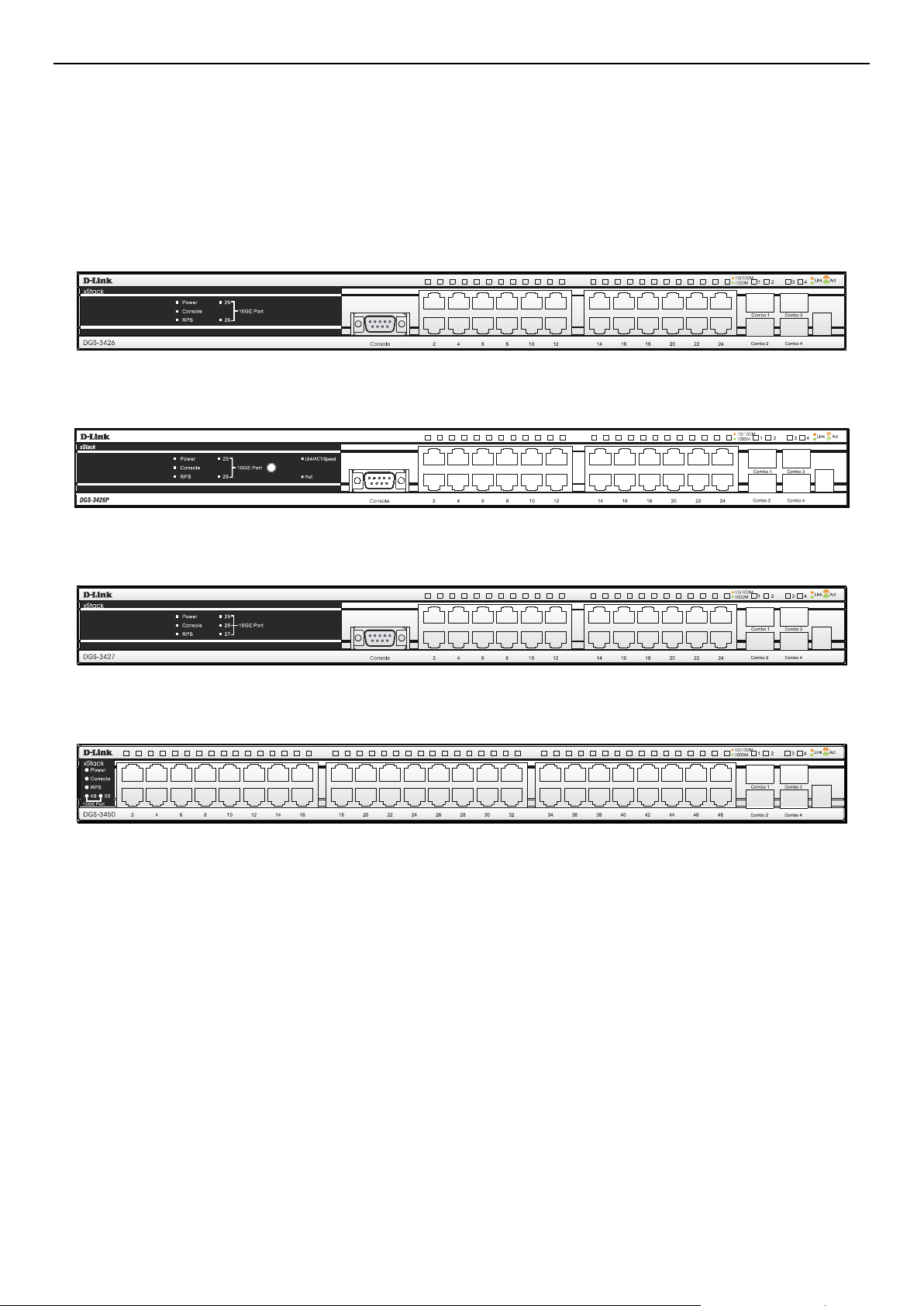
Front-Panel Components
The front panel of the Switch consists of LED indicators for Power, Master, Console, RPS, and for Link/A ct for each p ort on the
Switch including 10GE Ports for optional modules and SFP port LEDs. The front panel includes a seven-segment LED indicating
the Stack ID number. A separate table below describes LED indicators in more detail. DGS-3426P also includes a Mode Select
button for changing the mode Link/Act/State to PoE.
DGS-3426
Figure 1 - 1 Front Panel View of the DGS-3426
DGS-3426P
Figure 1 - 2 Front Panel View of the DGS-3426P
DGS-3427
DGS-3450
Figure 1 - 3 Front Panel View of the DGS-3427
Figure 1 - 4 Front Panel View of the DGS-3427
3
Page 13
xStack® DGS-3400 Series L a yer 2 Gig abit Ethernet Managed Switch
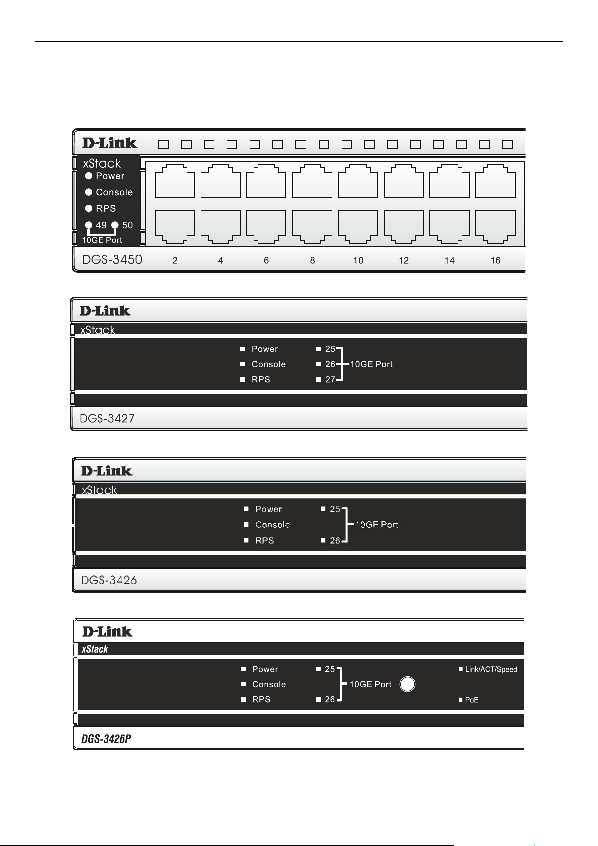
LED Indicators
The Switch supports LED indicators for Power, Console, RPS and Port LEDs including 10GE port LEDs for optional module
inserts.
Figure 1 - 5 LED Indicators on DGS-3450
Figure 1 - 6 LED Indicators on DGS-3427
Figure 1 - 7LED Indicators on DGS-3426
Figure 1 - 8 LED Indicators on DGS-3426P
4
Page 14

xStack® DGS-3400 Series L a yer 2 Gig abit Ethernet Managed Switch
LED Description
This LED will light green after powering the Switch on to indicate the ready state of the
Power
Console
device. The indicator is dark when the Switch is no longer receiving power (i.e powered
off).
This LED will blink green during the Power-On Self Test (POST). When the POST is
finished, the LED goes dark. The indicator will light steady green when an active console
link is in session via RS-232 console port.
RPS
Port LEDs
10GE Ports
Combo SFP Ports
Stack ID
Link/Act/Speed and PoE
(DGS-3426P only)
This LED will light when the internal power has failed and the RPS has taken over the
power supply to the Switch. Otherwise, it will remain dark.
One row of LEDs for each port is located above the ports on the front panel. The indicator
above the left side of a port corresponds to the port below the indicator in the upper row
of ports. The indicator above the right side of a port corresponds to the port below the
indicator in the lower row of ports. A steady green light denotes a valid 1000Mbps link on
the port while a blinking green light indicates activity on the port (at 1000Mbps). A steady
orange light denotes a valid 10 or 100Mbps link on the port while a blinking orange light
indicates activity on the port (at 100Mbps). These LEDs will remain dark if there is no link
on the port.
A steady green light denotes a valid link on the port while a blinking green light indicates
activity on the port. These LEDs will remain dark if there is no link on the port.
LED indicators for the Combo ports are located above the ports and numbered 1 – 4 for
Combo 1, Combo 2, etc. ports. A steady green light denotes a valid link on the port while
a blinking green light indicates activity on the port. These LEDs will remain dark if there is
no link on the port.
These two seven segment LEDs display the current switch stack order of the Switch while
in use.
To change the LED mode from Link/Act/Speed to PoE and vice versa, press the LED
Mode Select Button. T he Li nk/Ac t/Speed L ED will l ight solid gr een when se lected and will
shut off when PoE is selected. Likewise, when Link/Act/Spe ed is s elected, the PoE LED
shuts off and the Link/Act/Speed LED lights solid green.
5
Page 15

xStack® DGS-3400 Series L a yer 2 Gig abit Ethernet Managed Switch
Rear Panel Description
DGS-3426
The rear panel of the DGS-3426 contains an AC power connector, a redundant power supply connector and two empty slots for
optional module inserts.
Figure 1 - 9 Rear panel view of the DGS-3426
DGS-3426P
The rear panel of the DGS-3426P contains an AC power connector, a redundant power supply connector, a heat vent for the rear
fan and two empty slots for optional module inserts.
Figure 1 - 10 Rear panel view of the DGS-3426P
DGS-3427
The rear panel of the DGS-3427 contains an AC power connector, a redundant power supply connector and three empty slots for
optional module inserts.
Figure 1 - 11 Rear panel view of the DGS-3427
DGS-3450
The rear panel of the D G S -3450 contains an AC power connector, two empty slots for optional module inserts, a redundant power
supply connector, a RS-232 DCE console port for Switch management and a system fan vent.
Figure 1 - 12 Rear panel view of the DGS-3450
The AC power connector is a standard three-pronged connector that supports the power cord. Plug-in the female connector of the
provided power cord into this socket, and the male side of the cord into a power outlet. T he Switch automaticall y adjust s its p ower
setting to any supply voltage in the range from 100 ~ 240 VAC at 50 ~ 60 Hz.
The rear panel also includes an outlet for an optional external power supply. When a power failure occurs, the optional external
RPS will automatically assume the power supply for the Switch immediately.
6
Page 16

xStack® DGS-3400 Series L a yer 2 Gig abit Ethernet Managed Switch
Side Panel Descrip t ion
The system fans and heat vents located on each side dissipate heat. Do not block these openings. Leave at least 6 inches of space
at the rear and sides of the Switch for proper ventilation. B e reminded that without proper heat dissipation and air circulation,
system components might overhe at, which co uld lead to system failure and severely dama ge components.
Figure 1 - 13 Side Panel view of the DGS-3450
Figure 1 - 14 Side Panel view of the DGS-3426 and DGS-3427
Figure 1 - 15 Side Panel view of the DGS-3426P
7
Page 17

xStack® DGS-3400 Series L a yer 2 Gig abit Ethernet Managed Switch
•
•
•
•
•
•
•
Installation
Package Contents
Installation Guidelines
Installing the Switch without the Rack
Installing the Switch in a Rack
Mounting the Switch in a Standard 19" Rack
Power On
Power Failure
Installing the SFP Ports
The Optional Module
External Redundant Power System
Section 2
Package Contents
Open the shipping carton of the Switch and carefully unpack its contents. The carton should contain the following items:
1. One xStack
2. One AC power cord
3. Mounting kit (two brackets and screws)
4. Four rubber feet with adhesive backing
5. RS-232 console cable
6. One CD Kit for User’s Guide/CLI/D-View module
7. One CD Kit for D-View 5.1 Standard version (for Europe only)
8. Registration card & China Warranty Card ( for China only)
If any item is missing or damaged, please contact your local D-Link Reseller for replacement.
®
Stackable Switch
Installation Guidelines
Please follow these guidelines for setting up the Switch:
Install the Switch on a sturdy, level surface that can support at least 6.6 lb. (3 kg) of weight. Do not place heavy objects on the
Switch.
The power outlet should be within 1.82 meters (6 feet) of the Switch.
Visually inspect the power cord a nd see that it is fully secured to the AC power port.
Make sure that there is proper heat dissipation from and adequate ventilation around the Switch. Leave at least 10 cm (4
inches) of space at the front and r e a r of the Switch for ventilation.
Install the Switch in a fairly cool and dry place for the acceptable temperature and humidity operating ranges.
Install the Switch in a site free from strong electromagnetic field generators (such as motors), vibration, dust, and direct
exposure to sunlight.
When installing the Switch on a level surface, attach the rubber feet to the bottom of the device. The rubber feet cushion the
Switch, protect the casing from scratches and prevent it from scratching other surfaces.
8
Page 18

xStack® DGS-3400 Series L a yer 2 Gig abit Ethernet Managed Switch
Installing the Switch without the Rack
First, attach the rubber feet included with the Switch if installing on a desktop or shelf. Attach these cushio ni ng feet on t he bottom
at each corner of the device. Allow enough ventilation space between the Switch and any other objects in the vicinity.
Figure 2- 1. Prepare Switch for installation on a desktop or shelf
Installing the Switch in a Rack
The Switch can be mounted in a standard 19" rack. Use the following diagrams as a guide.
Figure 2- 2. Fasten mounting brackets to Switch
Fasten the mounting brackets to the Switch using the screws provided. With the brackets attached securely, the Switch can be
mounted in a standard rack as shown below.
9
Page 19

xStack® DGS-3400 Series L a yer 2 Gig abit Ethernet Managed Switch
Mounting the Switch in a Standard 19" Rack
Figure 2- 3. Installing Switch in a rack
Power On
1. Plug one end o f the AC po wer cor d into the p ower conne cto r o f the S witch a nd t he ot her end i nto the loc al p ower s our ce
outlet.
2. After powering on the Switch, the LED indic ator s will mo mentaril y blin k. T his blinking of the LED indicators represents
a reset of the system.
Power Failure
As a precaut ion, in the event of a power failure, unplug the Switch. When power is re sumed, plug the Switch back in.
10
Page 20

xStack® DGS-3400 Series L a yer 2 Gig abit Ethernet Managed Switch
Installing the SFP Ports
The xStack® DGS-3400 Series are equipped with SFP (Small Form Factor Portable) ports, which are to be used with fiber -optical
transceiver c ab li ng in order t o up lin k var io us o t he r ne t wo r ki ng d e vi ce s for a gigabit link t ha t ma y sp a n gre at di stances. T he se SFP
ports support full-duplex transmissions, have auto-negotia ti o n a nd c an b e us ed wi th DE M-310GT (1000BASE-LX), DEM-311GT
(1000BASE-SX), DEM-314GT (1000BASE-LHX) and DEM-315GT (1000BASE-ZX) transceivers. See the figure below for
installing the SFP ports in the Switch.
Figure 2- 4. Inserting the fiber-optic transceivers into the DGS-3426
11
Page 21

xStack® DGS-3400 Series L a yer 2 Gig abit Ethernet Managed Switch
The Optional Module
The rear panel of the DGS-3426, DGS-3426P, DGS-3427 and DGS-3450 include open slots that may be equipped with the DEM410X 1-port 10GE XFP stacking uplink module, or a DEM-410CX 1-port 10GBASE-CX4 stacking uplink module, both sold
separately. These mod ul es may be use d to stack switches in a switch stack using a Duplex Ring or Duplex Chain topology.
Adding the DEM-410X optional module will allow the administrator to transmit data at a rate of ten gigabits a second. The
module port(s) are compliant with standard IEEE 802.3ae, support full-duplex tra nsmissions only and must be used with XFP
MSA compliant transceivers.
The DEM-410CX uses copper wire medium, not optic fiber and therefore has a transmit length limit up to 1 meter. Co mpliant
with the IEEE802.3ak standard, this module uses a 4-laned copper connector for data transfer in full-duplex mode within a
stacking configuration.
To install t hese modules in the DGS-3400 Series, follow the si mple ste ps listed below.
CAUTION: Before adding the optional module, make sure to disconnect all power sources
connected to the Switch. Failure to do so may result in an electrical shock, which may cause
damage, not only to the individual but to the Switch as wel l.
At the back of the Switch to the left is the slot for the op tional module. This slot must be covered with the faceplate if the slot is
not being used. If a module will be installe d in an available slot, the faceplate is easily removed by loosening the screws and
pulling off the plate.
The front panels of the available modules are shown here:
Figure 2- 5. Front Panel of the DEM-410X
Figure 2- 6. Front Panel of the DEM-410CX
12
Page 22

xStack® DGS-3400 Series L a yer 2 Gig abit Ethernet Managed Switch
Installing the Module
Unplug the Switch before removing the faceplate c overing the empty slot. T o install the module, slide it in to the availa ble slot at
the rear of the Switch until it r eaches the back, a s shown in the follo wing figure. Gentl y, but firmly push i n on the module to
secure it to the Switch. The module should fit snugly into the corresponding receptors.
Figure 2- 7. Inserting the optional module into the Switch (DGS-3450)
Now tighten the two screws at adjacent ends of the module into the available screw holes on the Switch. The upgraded Switch is
now ready for use.
Figure 2- 8. DGS-3450 with optional DEM-410X module installed
13
Page 23

xStack® DGS-3400 Series L a yer 2 Gig abit Ethernet Managed Switch
External Redundant Power System
The Switch supports an external redundant power system. The diagrams below illustrate a proper RPS power connection to the
Switch. Please consult the documentation for information on power cabling and connectors and setup procedure.
Figure 2- 9. The DGS-3450 with the DPS-500 chassis RPS
Figure 2- 10. The DGS-3450 with the DPS-500 Redundant External Power Supply
14
Page 24

xStack® DGS-3400 Series L a yer 2 Gig abit Ethernet Managed Switch
Alternate to the other Switches in the xStac k
®
DGS-3400 Series, the DGS-3426P utilizes the DPS-600 as its External Redundant
Power Supply. The DPS-600 is the ONLY RPS to be used with the DGS-3426P.
NOTE: See the DPS-500 or DPS-600 documentation for more information.
CAUTION: Do not use the Switch (except DGS-3426P) with any redundant power system
other than the DPS-500.
15
Page 25

xStack® DGS-3400 Series L a yer 2 Gig abit Ethernet Managed Switch
•
•
•
•
•
Section 3
Connecting the Switch
Switch to End Node
Switch to Switch
Connecting To Network Backbone or Server
NOTE: All high-performance N-Way Ethernet ports can support both MDI-II and MDI-X connections.
Switch to End Node
End nodes include PCs outfitted with a 10, 100 or 1000 Mbps RJ-45 Ethernet Network Interface Card (NIC) and routers.
An end node connects to the Switch via a twisted-pair UTP/STP cable. Connect the end node to any of the 1000BASE-T ports of
the Switch.
The Link/Ac t LEDs for e ach UTP p ort wil l lig ht gree n or a mber when t he lin k is va lid. A b lin king LED indic ate s pac ket activity
on that port.
Switch to Switch
There is a great deal of flexibility on how connections are made using the appropriate cabling.
Connect a 10BASE-T hub or switch to the Switch via a twisted-pair Category 3, 4 or 5 UTP/STP cable.
Connect a 100BASE-TX hub or switch to the Switch via a twisted-pair Category 5 UTP/STP cable.
Connect 1000BASE-T switch to the Switch via a twisted pair Category 5e UTP/STP cable.
Connect 10G optional module ports at the rear of the device using CX4 or fiber-optic cables
Connect switch supporting a fiber-op tic uplink to the Switch’s SFP ports via fiber-optic cabling. See cabling guideli nes in
Appendix B for more information.
Figure 3 - 1 Connect the Switch to a port on a switch with straight or crossover cable
16
Page 26

xStack® DGS-3400 Series L a yer 2 Gig abit Ethernet Managed Switch
Figure 3 - 2 Connect the Switch utilizing the 10G optional modules at the rear of the Switch.
Connecting To Network Backbone or Server
The combo SFP ports and the 1000BASE-T ports are ideal for uplinking to a network backbone, server or server farm. The copper
ports operate at a speed of 1000, 100 or 10Mbps in full or half duplex mode. The fiber-optic ports can operate at 1000Mbps in full
duplex mode only.
Connections to the Gigabit Ethernet ports are made using a fiber-optic cable or Category 5e copper cable, depending on the type
of port. A valid connection is indica te d when the Link LED is lit.
Figure 3 - 3 DGS-3400 uplink connection to a server or switch stack, and downlink connection to a
PC
17
Page 27

xStack® DGS-3400 Series L a yer 2 Gig abit Ethernet Managed Switch
Section 4
Introduction to Switch Management
Management Options
Connecting the Console Port (RS-232 DCE)
Managing the Switch for the First Time
Password Protection
SNMP Settings
IP Address Assignment
Management Options
This system ma y be managed out-of-band through the console port on the front panel or in-band usin g Telne t. T he user may also
choose the web-based management, accessible through a web browser.
1. Web-based Management Interface
After successfully installing the Switch, the user can configure the Switch, monitor the LED pa nel, and display stati stics
graphically using a web browser, such as Netscape Navigator (version 6.2 and higher) or Microsoft® Internet Explorer
(version 5. 0 and higher).
2. SNMP-Based Management
The Switch can be managed with an SNMP-compatible console program. The Switch supports SNMP version 1.0,
version 2.0 and version 3.0. The SNMP agent decodes the incoming SNMP messages and responds to requests with MIB
objects stored in the database. The SNMP agent updates the MIB objects to generate statistics and counters.
3. Command Line Console Interface through the Serial Port
The user can also connect a computer or terminal to the serial console port to access the Switch. The command-linedriven interface provides complete access to all Switch management features.
18
Page 28

xStack® DGS-3400 Series L a yer 2 Gig abit Ethernet Managed Switch
•
•
•
•
•
•
•
•
•
•
•
•
•
Connecting the Console Port (RS-232 DCE)
The Switch provides an RS-232 serial port that enables a connection to a computer or terminal for monitoring and configuring the
Switch. This port is a female DB-9 connector, implemented as a data terminal equipment (DTE) connection.
To use the console port, the following equipment is needed:
A terminal or a computer with both a serial port and the ability to emulate a terminal.
A null modem or crossover RS-232 cable with a female DB-9 connector for the console port on the Switch.
To connect a terminal to the conso le port:
Connect the female connector of the RS-232 cable directly to the console port on the Switch, and tighten the captive retaining
screws.
Connect the other end of the cable to a terminal or to the serial connector of a computer running terminal emulation software. Set
the terminal emulation software a s follows:
Select the appropriate serial port (COM port 1 or COM port 2).
Set the data rate to 115200 baud.
Set the data format to 8 data bits, 1 stop bit, and no parity.
Set flow control to none.
Under Properties, select VT100 for Emulation mode.
Select Terminal ke ys fo r Function, Arrow and Ctrl keys. Make sure to use Terminal keys (not Windows keys) are selected.
NOTE: When using HyperTerminal with the Microsoft® Windows® 2000 operating system, ensure
that Windows 2000 Service Pack 2 or later is installed. Windows 2000 Service Pack 2 allows use
of arrow keys in HyperTerminal's VT100 emulation. See www.microsoft.com for information on
Windows 2000 service packs.
After you have correctly set up the terminal, plug the power cable into the power receptacle on the back of the Switch. The
boot sequence appears in the terminal.
After the boot sequence completes, the console login screen displays.
If the user has not logged into the command line interface (CLI) program, press the Enter key at the User name and password
prompts. There is no default user name and password for the Switch. The administrator must first create user names and
passwords. If user accounts have been previously set up, log in and continue to configure the Switch.
Enter the commands to complete desired tasks. Many commands require administrator-level access privileges. Read the next
section for more information on setting up user accounts. See the xStack
documentation CD for a list of all commands and additional information on using the CLI.
To end a management session, use the logout command or c lose the emu la tor program.
If problems occur in making this connection on a PC, make sure the emulation is set to VT-100. The emulation settings can be
configured by clicking o n the File menu in the Hyper Terminal wind ow by clicki ng on Properties in the d rop-down me nu, and
then clicki ng the Settings tab. This is where you will find the Emulation options. If you still do not see anything, try rebooting
the Switch by disconnecting its power supply.
®
DGS-3400 Series CLI Manual on the
19
Page 29

xStack® DGS-3400 Series L a yer 2 Gig abit Ethernet Managed Switch
Once connected to the console, the screen below will appear on the console screen. This is where the user will enter commands to
perform all the available management functions. The Switch will prompt the user to enter a user name and a password. Upon the
initial connection, there is no user name or password and therefore just press enter twice to access the command line interface.
GS-3450 Gigabit Ethernet Switch
Command Line Interface
Firmware: Build 3.00.B10
Copyright(C) 2012 D-Link Corporation. All rights reserved.
UserName:
Figure 4 - 1 Initial Screen after first connection
Managing the Switch for the First Time
The Switch sup ports user -based security that can allow prevention of unauthorized users from accessing the Switch or changing
its settings. This section tells how to log onto the Switch via out-if-band console connection.
NOTE: The passwords used to access the Switch are case-sensitive; for example, "S"
is not the same as "s."
NOTE: Press Ctrl+R to refresh the screen. This command can be used at any time to
force the console program in the Switch to refresh the console screen.
Press Enter in both the Username and Password fields. Then access will be given to enter commands after the command prompt
DGS-3426: admin#, DGS-3426P: admin#, DGS-3427: admin# or DGS-3450: admin# as shown bel ow:
DGS-3450 Gigabit Ethernet Switch
Command Line Interface
Firmware: Build 3.00.B10
Copyright(C) 2012 D-Link Corporation. All rights reserved.
UserName:
PassWord:
DGS-3450:admin#
Figure 4 - 2 Initial screen, first time connecting to the Switch
Press Enter in both the Username and Password fields. Then access will be given to enter commands after the command prompt
DGS-3426:admin#, DGS-3426P:admin#, DGS-3427:admin# or DGS-3450:admin# as shown below:
20
Page 30

xStack® DGS-3400 Series L a yer 2 Gig abit Ethernet Managed Switch
There is no initial username or pass word. Leave the Username and Password fields blank.
NOTE: The first user automatically gets Administrator level privileges. At least one Admin-level
user account must be created for the Switch.
Password Protection
The xStack® DGS-3400 Series do not have a default user name and password. One of the first tasks when settings up the Switch is
to create user accounts. Logging in using a predefined administrator-level user name will give the user privileged access to the
Switch's management software.
After the initi al lo gin, de fine ne w pa ss words for bot h defa ul t user na mes to pr eve nt una ut hori zed acce ss to the S witc h, and rec ord
the passwords for future reference.
To create an administrator-level account for the Switch, do the following:
1. At the CLI login prompt, enter create account admin followed by the <user name> and press the Enter key.
2. The Switch will then prompt the user to provide a password. Type the <password> used for the administrator
account being created and press the Enter key.
3. Once entered, the Switch will again ask the user to enter the same password again to verify it. Type the same
password and press the Enter key.
4. A “Success” response by the Switch will verify the creation of the new administrator.
NOTE: Passwords are case sensitive. User names and passwords can be up
to 15 characters in length.
The sample below illustrates a successful creation of a new administrator-level account with the user name "newmanager".
DGS-3450:admin#create account admin newmanager
Command: create account admin newmanager
Enter a case-sensitive new password:***
Enter the new password again for confirmation:***
Success.
DGS-3450:admin#
Figure 4 - 3 Creating an Account on the Switch
NOTICE: CLI configuration commands only modify the running configuration file and are not
saved when the Switch is rebooted. To save all configuration changes in non-volatile memory,
use the save command to copy the running configuration file to the startup configuration.
21
Page 31

xStack® DGS-3400 Series L a yer 2 Gig abit Ethernet Managed Switch
•
•
SNMP Settings
Simple Network Management Protocol (SNMP) is an OSI Layer 7 (Application Layer) designed specifically for managing and
monitoring network device s. SNMP enab les network mana gement statio ns to read and modi fy the settings o f gateways, ro uters,
switches and other network devices. Use SNMP to configure system features for proper operation, monitor performance and
detect potential problems in the Switch, switch group or network.
Managed devices that support SNMP include software (referred to as an agent), which runs locally on the device. A defined set of
variables (managed objects) is maintained by the SNMP agent and used to manage the device. These objects are defined in a
Management Information Base (MIB), which provides a standard presentation of the information controlled by the on-board
SNMP agent. SNMP defines both the format of the MIB specifications and the protocol used to access this information over the
network.
®
The xStack
to monitor a nd control the Switch. The three ve rsions of SNMP var y in the level o f securit y provided be tween the ma nagement
station and the network device.
In SNMP v.1 and v.2, user authentication is accomplished using 'community string s', whi ch func tion like pass words. The remote
user SNMP application and the Switch SNMP must use the same community string. SNMP packets from any station that has not
been authenticated are ignored (dropped).
The default community strings for the Switch used for SNMP v.1 and v.2 management acc ess are:
public – Allows authorized management stations to retrieve MI B objects.
DGS-3400 Series support SNMP versions 1, 2c, and 3. The administrator may specify which version of SNMP to us e
private – Allows authorized management stations to retrieve and modify MIB objects.
SNMP v.3 uses a more sophisticated authentication process that is sepa rated into two parts. T he first part is to mainta in a list of
users and their attributes that are allowed to act as SNMP managers. The second part describes what each user on that list can do
as an SNMP manager.
The Switch allo ws groups of users to be listed and configured with a shared set of privileges. The SNMP version may also be set
for a listed group of SNMP managers. Thus, a group of SNMP managers can be created to view read-only information or receive
traps using S NMP v.1 while assigni ng a higher l evel of secu rity to another group, granting read/write privileges using SNMP v.3.
Using SNMP v.3 individual users or groups of SNMP managers can be allowed to perform or be restricted from performing
specific SNMP management functions. The functions allowed or restricted are defined using the Object Identifier (OID)
associated with a specific MIB. An additional layer of security is available for SNMP v.3 in that SNMP messages may be
encrypted. To read more about how to configure SNMP v.3 settings for the Switch read the section entitled Management.
Traps
Traps are messages that alert network personnel of events that occur on the Switch. The events can be as serious as a reboot
(someone accidentally turned OFF the Switch), or less serious like a po rt status change . The Switch genera tes traps and se nds
them to the tr ap r ec ip ie nt ( o r net work ma na ge r) . Typical trap s i ncl ud e tr ap me ssa ge s fo r Aut he nti cation Fail ure , T o po lo gy C hange
and Broadcast\Multicast Storm.
MIBs
The Switch in the Management Information Base (MIB) stores management and counter information. The Switch uses the
standard MIB-II Management Information Base module. Consequently, values for MIB objects can be retrieved from any SNMPbased network management software. In addition to the standard MIB-II, the Switch also supports its own prop rietary enterprise
MIB as an extended Management Information Base. The proprietary MIB may also be retrieved by specifying the MIB Object
Identifier. MIB values can be either read-only or read-write.
IP Address Assignment
An IP Address must be assigned to each switch, which is used for communication with an SNMP network manager or other
TCP/IP application (for example BOOTP, TFTP). The Switch's default IP address is 10.90.90.90. The user may change the default
Switch IP address to meet the specification of your networking address s cheme.
22
Page 32

xStack® DGS-3400 Series L a yer 2 Gig abit Ethernet Managed Switch
DGS-3450:admin#show switch
CTRL+C ESC q Quit SPACE n Next Page ENTER Next Entry a All
The Switch is also assigned a unique MAC address by the factory. This MAC address cannot be changed, and can be found by
entering the command "show switch" into the command line interface, as shown below.
Command: show switch
Device Type : DGS-3450 Gigabit Ethernet Switch
MAC Address : 00-22-B0-DE-F0-46
IP Address : 10.90.90.90 (Manual)
VLAN Name : default
Subnet Mask : 255.0.0.0
Default Gateway : 0.0.0.0
Boot PROM Version : Build 1.00-B13
Firmware Version : Build 3.00.B10
Hardware Version : A2
System Name :
System Location :
System Uptime : 0 days, 0 hours, 12 minutes, 26 seconds
System Contact :
Spanning Tree : Disabled
GVRP : Disabled
IGMP Snooping : Disabled
MLD Snooping : Disabled
RIP : Disabled
RIPng : Disabled
TELNET : Enabled (TCP 23)
WEB : Enabled (TCP 80)
SNMP : Disabled
Figure 4 - 4 “show switch” command
The Switch's MAC address also appears in Sw itch Info rma tion menu of the web-based management interface. The IP address for
the Switch must be set before it can be managed with the Web-based or SNMP manager, Telnet or SSH. The Switch IP address
can be automatically set using BOOTP or DHCP protocols, in which case the actual address assigned to the Switch must be
known. The IP address may be set using the Command Line Interface (CLI) over the console serial port as follows:
Starting at the command line prompt, enter the command:
config ipif System ipaddress xxx.xxx.xxx.xxx/yyy.yyy.yyy.yyy
Where the x's represent the IP address to be assigned to the IP interface named System and the y's represent the corresponding
subnet mas k. Alternati vely, the user can enter c onfig ipif System ipa ddress xxx.xxx.xxx. xxx/z. Where the x's represent the IP
address to be assigned to the IP interface named System and the z represents the corresponding number of subnets in CIDR
notation. The IP interface named System on the Switch can be assigned an IP address and subnet mask, which can then be used to
connect a management station to the Switch's Telnet or Web-based management agent.
23
Page 33

xStack® DGS-3400 Series L a yer 2 Gig abit Ethernet Managed Switch
DGS-3450:admin#config ipif System ipaddress 10.73.21.10/255.0.0.0
Command: config ipif System ipaddress 10.73.21.10/8
Success.
DGS-3450:admin#
Figure 4 - 5 Assigning the Switch an IP Address
In the above example, the Switch was assigned an IP address of 10.53.13.26 with a subnet mask of 255.0.0.0. The system message
Success indicates that the com mand was executed successfully. The Switch can now be configured and managed via Telnet and
the CLI or via the Web-based manageme nt .
NOTE: The DGS-3400 Series have the c apability to b e configured for an IP address of 0.0.0.0, or,
in essence, have no IP address. This function maybe used to disable Layer 3 functions of the
Switch. When the IP addre ss is set to 0.0.0.0 (inval id IP addres s), the Switc h can onl y be managed
through the conso le port or SIM. Other m anagement applicat ions such as Telnet, W eb-based and
SNMP cannot be used to manage the Switch when its IP address is 0.0.0.0.
24
Page 34

xStack® DGS-3400 Series L a yer 2 Gig abit Ethernet Managed Switch
Section 5
Web-based Switch Configuration
Introduction
Logging on to the Web Manager
Web-Based User Interface
Web Pages
Introduction
All software functions of the xStack® DGS-3400 Series can be managed, configured and monitored via the embedded web-based
(HTML) interface. Manage the Switch from remote stations anywhere on the network through a standard browser. The browser
acts as a universal access tool and can communicate directly with the Switch using the HTTP protocol.
The Web-based management module and the Console program (and Telnet) are different ways to access the same internal
switching so ftware and configur e it. Thus, al l settings e ncountere d in web-based management are the same as those found in the
console program.
25
Page 35

xStack® DGS-3400 Series L a yer 2 Gig abit Ethernet Managed Switch
Logging in to the Web Manager
To begin mana gin g the S wit ch, simpl y run the browser installed on your computer and point it to the IP address you have defined
for the device. The URL in the address bar should read something like: http://123.123.123.123, where the numbers 123 represent
the IP address of the Switch.
NOTE: The factory default IP address is 10.90.90.90.
This opens t he management module's user authentication window, as s een below.
Figure 5 - 1 Enter Network Password window
Leave both t he User Name field and the Password field blank and cl ick OK. This will open the We b-based user interface. The
Switch management features available in the web-based manager are explained below.
26
Page 36

xStack® DGS-3400 Series L a yer 2 Gig abit Ethernet Managed Switch
Area 2
Area 1
Area 3
Web-based User Interface
The user interface provides access to various Switch configuration and management screens, allows the user to view performance
statistics, and permits graphic a l monitoring of the system status.
Areas of the User Interface
The figure below shows the user interface. Three distinct areas divide the user interface, as described in the table.
Area Function
Area 1
Area 2
Area 3
Select the menu or window to display. Open folders and click the hyperlinked menu buttons and
subfolders contained within them to display menus. Click the D-Link logo to go to the D-Link website.
Presents a graphica l near real-time image of the fron t panel of the Switch. This area disp lays the
Switch's ports and expansion modules, showing port activity, duplex mode, or flow control,
depending on the specified mode.
Some management functions, including port configuration are accessible here.
Presents switch information based on user selection and the entry of configuration data.
Figure 5 - 2 Main Web-Manager Screen
27
Page 37

xStack® DGS-3400 Series L a yer 2 Gig abit Ethernet Managed Switch
Web Pages
When connec ting t o the mana gement mode of the Switch with a web bro wser, a login screen is displayed. Enter a user name and
password to access the Switch's management mode.
Below is a list of the main folders available in the web interface:
Administration – Contains the following menu pages and sub-directories: IP Address, Interface Settings, Stacking, Port
Configurati on, User Acco un ts, Pa ssword Encr ypti on, M irr or, Syste m Lo g, S yste m Seve rit y Set tin gs, Co mma nd Lo gg ing Se tti ngs,
SNTP Settings, MAC Notification Settings, TFTP Services, Multiple Image Services, RCP, Ping Test, IPv6 Neighbor, Route
Redistribution Settings, Static/Defa ult Route Settings, Route Preference Settings, Gratuit ous ARP Settings, Static ARP Settings,
DHCP Auto Configuration Settings, DH CP/BOOT P Relay, DHCP/BOOT P Local Relay Settings, DH CPv6 Relay, DHC P Server,
DHCPv6 Server, Filter DHCP Server, Lyer 2 Protocol Tunneling Settings, RSPAN, DNS Relay, DNS Resolver, SNMP Manager,
Trap Source Interface Settings, PoE (DGS-3426P only), sFlow, IP Multicast VLAN Replicatio n, Single IP M anageme nt Se ttings,
RIP, and I P Tunnel Setti ngs.
L2 Features – Contains the following menu pages and sub-directories: VLAN, Trunking, IGMP Snooping, MLD Snooping,
Loopback Detection Global Settings, Spanning Tree, Forwarding & Filtering, LLDP, Q-in-Q, ERPS, DU LD Settings, and NLB
Multicast FDB Settings.
QoS – Contains the following menu pages and sub-directories: 802.1p Settings, Bandwidth Co ntrol, HOL Prevention Settings,
and Schedule Settings.
ACL – Co ntains the following men u pages and sub -directories: Time Range, Access Profile Table, ACL Flow Meter and CPU
Interface Filtering.
Security – Contains the following menu pages and sub-directories: Authorization Net work State Settings, Traffic Control, Port
Security, I P-MAC-Port Binding, 802.1X, Web-based Access Control (WAC), Trust Host, B PDU Attach Pro tection Settings, ARP
Spoofing Prevention Settings, Access Authentication Control, MAC-based Access Control, Safeguard Engine, Traffic
Segmentation, SSL, SSH, Common Authentication, and Japanese Web-based Access Control (JWAC).
Monitoring – Co ntains the fo llowing menu page s and sub -directories: Device Statu s, Stacking Information (on ly when stacking
mode is enabled), Stacking Device(only when stacking mode is enabled), Module Information, DRAM & Flash Utilization, CPU
Utilization, Port Utilization, Packets, Err ors, Packet Size, Browse Router Port, Browse MLD Router Port, VLAN Status, VLAN
Status Port, Port Access Control, MAC Address Table, IGMP Snooping Group, IGMP Snooping Data Driven Group, MLD
Snooping Group, MLD Snooping Data Driven Group, Trace Route, Switch Logs, Browse ARP Table, Session Table, IP
Forwarding Table, Routing Table, and MAC-based Access Control Authenticatio n Status.
Save Services – Contains the following menu pages and sub-directories: Save Changes, Configure Information, and Current
Configurati on Settings.
Reset, Reboot System and Logout menu links are displayed in the main directory.
NOTE: Be sure to configure the user name and password in the User
Accounts menu before connecting the Switch to the greater network.
28
Page 38

xStack® DGS-3400 Series L a yer 2 Gig abit Ethernet Managed Switch
Technical Specifications
Specifications listed here apply to a ll Switches in the DGS-3400 Series except where otherwise noted.
General
Appendix A
Standards
Protocols
Data Transfer Rates:
Ethernet
Fast Ethernet
Gigabit Ethernet
Fiber Optic
IEEE 802.3 10BASE-T Ethernet
IEEE 802.3u 100BASE-TX Fast Ethernet
IEEE 802.3ab 1000BASE-T Gigabit Ethernet
IEEE 802.3z 1000BASE-T (SFP “Mini GBIC”)
IEEE 802.3ae (10G Optional Modules)
IEEE 802.1D/w/s Spanning Tree (Rapid, Multiple)
IEEE 802.1P/Q VLAN
IEEE 802.1p Priority Queues
IEEE 802.1v Protocol VLAN
IEEE 802.1X Network Access Control
IEEE 802.3 Nway auto-negotiation
IEEE 802.3ad Link Aggregation Control
IEEE 802.3x Full-duplex Flow Control
IEEE 802.1u Fast Ethernet
IEEE 802.3af Power-over-Ethernet
CSMA/CD
Half-duplex Full-duplex
10 Mbps 20Mbps
100Mbps 200Mbps
1000Mbps 2000Mbps
SFP (Mini GBIC) Support
IEEE 802.3z 1000BASE-LX (DEM-310GT transceiver)
IEEE 802.3z 1000BASE-SX (DEM-311GT transceiver)
IEEE 802.3z 1000BASE-SX (DEM-312GT2 transceiver)
IEEE 802.3z 1000BASE-LHX (DEM-314GT transceiver)
IEEE 802.3z 1000BASE-ZX (DEM-315GT transceiver)
WDM Single Mode Transceiver 10km (DEM-330T/R)
WDM Single Mode Transceiver 40km (DEM-331T/R)
Topology
Network Cables
Duplex Ring, Duplex Chain
Cat.5 Enhanced for 1000BASE-T
UTP Cat.5, Cat. 5 Enhanced for 100BASE-TX
UTP Cat.3, 4, 5 for 10BASE-T
EIA/TIA-568 100-ohm screened twisted-pair (STP)(100m)
29
Page 39

xStack® DGS-3400 Series L a yer 2 Gig abit Ethernet Managed Switch
Physical and Environmental
Internal Power Supply
Redundant Power Supply
Power Consumption DGS-3400 Series
DC Fan:
Operating Temperature
Storage Temperature
Humidity
Dimensions
Weight DGS-3400 Series
AC Input: 100 - 240 VAC, 50-60 Hz
DGS-3426 (78.2 Watts)
DGS-3426P (496 Watts)
DGS-3427 (86.68 Watts)
DGS-3450 (144.47 Watts)
12v
0 - 40°C
-40 - 70°C
5 - 95% non-condensing
441mm x 389mm x 44mm
DGS-3426 (5.42 kg)
DGS-3426P (6 kg)
DGS-3427 (5.51 kg)
DGS-3450 (5.74 kg)
Module Inserts
DEM-410CX (0.015 Watts)
DEM-410X (6.16 Watts)
Module Inserts
DEM-410CX (0.16 kg)
DEM-410X (0.18 kg)
EMI:
Safety:
Transmission Method
Packet Buffer
Packet Filtering / Forwarding Rate
MAC Address Learning
Priority Queues
Forwarding Table Age Time
CE class A, FCC Class A
CSA International, CB Report
Performance
Store-and-forward
0.75 MB per device
Full-wire speed for all connections
1,488,095 pps per port (for 1000Mbps)
Automatic update. Supports 8K MAC address.
8 Priority Queues per port.
Max age: 10-1000000 seconds. Default = 300.
30
Page 40

xStack® DGS-3400 Series L a yer 2 Gig abit Ethernet Managed Switch
Appendix B
Cables and Connectors
When connec ting the Switch to another switch, a bridge or hub, a normal cable is necessary. Please review these products for
matching cable pin assignmen t.
The following diagrams and tables show the standard RJ -45 r ecep tacle/connector and their pin assignments.
Appendix B - 1 The standard RJ-45 port and connector
RJ-45 Pin Assignments
Contact MDI-X Port MDI-II Port
1 RD+ (receive) TD+ (transmit)
2 RD- (receive) TD- (transmit)
3 TD+ (transmit) RD+ (receive)
4 1000BASE-T 1000BASE-T
5 1000BASE-T 1000BASE-T
6 TD- (transmit) RD- (receive)
7 1000BASE-T 1000BASE-T
8 1000BASE-T 1000BASE-T
Appendix B - 2 The standard RJ-45 pin assignments
31
Page 41

xStack® DGS-3400 Series L a yer 2 Gig abit Ethernet Managed Switch
Appendix C
Cable Lengths
Use the following table to as a guide for the maximum cable lengths.
Standard Media Type Maximum Distance
Mini-GBIC 1000BASE-LX, Single-mode fiber module
1000BASE-SX, Multi-mode fiber module
1000BASE-LHX, Single-mode fiber module
1000BASE-ZX, Single-mode fiber module
1000BASE-T Category 5e UTP Cable
Category 5 UTP Cable (1000 Mbps)
100BASE-TX Category 5 UTP Cable (100 Mbps) 100m
10BASE-T Category 3 UTP Cable (10 Mbps) 100m
10km
550m / 2km
40km
80km
100m
32
Page 42

Glossary
1000BASE-SX: A short laser wavelength on multimode fiber optic cable for a maximum length of 550 meters
1000BASE-LX: A long wavelength for a "long haul" fiber optic cable for a maximum length of 10 kilometers
100BASE-FX: 100Mbps Ethernet implementation over fiber.
100BASE-TX: 100Mbps Ethernet implementation over Category 5 and Type 1 Twisted Pair cabling.
10BASE-T: The IEEE 802.3 specification for Ethernet over Unshielded Twisted Pair (UTP) cabling.
ageing: The automatic removal of dynamic entries from the Switch Database which have timed-out and are no longer valid.
ATM: Asynchrono us Tra nsfer Mode. A connection oriented transmission protocol based on fixed length cells (packets). ATM is
designed to carry a complete range of user traffic, including voice, data and video signals.
auto-negotiation: A feature on a port which allows it to advertise its capabilities for speed, duplex and flow control. When
connected to an end station that also supports auto-negotiation, the link can self-detect its optimum oper a ting setup.
backbone port: A port which does not learn device addresses, and which receives all frames with an unknown address. Backbone
ports are normally used to connect the Switch to the backbone of your network. Note that backbone ports were formerly known as
designated downlink ports.
backbone: The part of a network used as the primary path for transporting traffic between network segments.
bandwidth: Information capacity, measured in bits per second, that a channel can transmit. The bandwidth of Ethernet is 10Mb p s,
the bandwidth of Fast Ethernet is 100Mbps.
baud rate: The switching sp eed o f a line. Also known as line speed between network segments.
BOOTP: The BOOTP protocol allows automatic mapping of an IP address to a given MAC address each time a device is started.
In additio n, the proto col can assi gn the subnet mask and d efault gate way to a device.
bridge: A device that inter connects local or re mote networks no matter what higher leve l protocols are involved. Bridges form a
single logical network, centraliz ing network administration.
broadcast: A message sent to all destination devices on the network.
broadcast storm: Multiple simultaneous broadcasts that typically absorb available network bandwidth and can cause network
failure.
console port: The port on the Switch accepting a terminal or modem connector. It changes the parallel arrangement of data within
computers to the serial form used o n d a ta transmission links. This por t is most o ften used for dedicated local management.
CSMA/CD: Channel a ccess method used b y Etherne t and IEEE 80 2.3 stand ards in which de vices tr ansmit o nly af ter find ing the
data channel clear for some period of time. When two devices transmit simultaneously, a collision occurs and the colliding
devices delay their retransmissions for a random amount of time.
data center switching : The point o f ag grega ti on wit hin a corpo rate network where a switch provides hi gh-performance access to
server farms, a high-speed backbone connection and a control point for network management and security.
Ethernet: A LAN specification developed jointly by Xerox, Intel and Digital Equipment Corporation. Ethernet net works o pera te
at 10Mbps using CSMA/CD to run over cabling.
Fast Ethernet: 100Mbps technology based on the CSMA/CD network access method.
Flow Control: (IEEE 802.3X) A means of holding packets back at the transmit port of the connected end station. Prevents packet
loss at a congested switch port.
forwarding: The process of sending a packet toward its destination by an internetworking device.
full duplex: A system that allows packets to be transmitted and received at the same time and, in effect, doubles the potential
throughput of a link.
half duplex: A system that allows packets to be transmitted a nd received, but not at the same time. Con trast with full duplex.
IP address: Inter net P ro toco l ad dre ss. A unique ide ntifier fo r a device attached to a network using TCP/IP. T he address is written
as four octets separated with full-stops (periods), and is made up of a network section, an optional subnet section and a host
section.
IPX: Internetwork Packet Exchange. A protocol allowing communication in a NetWare network.
LAN - Local Area Network: A network of connected computing resources (such as PCs, printers, servers) covering a relatively
small geographic area (usually not larger than a floor or building). Characterized by high data rates and low error rates.
Page 43

latency: The delay between the time a device receives a packet and the time the packet is forwarded out of the destination port.
line speed: See baud rate.
main port: The port in a resilient link that carries data traffic in normal operating conditi ons.
MDI - Medium Dependent Interface: An Ethernet port connection where the transmitter of one device is connected to the
receiver of another device.
MDI-X - Medium Dependent Interface Cross-over: An E thernet port co nnectio n wher e the internal transmit and receive lines
are crossed.
MIB - Management Information Base: Stores a device's management characteristics and parameters. MIBs are used by the
Simple Network Management Protocol (SNMP) to contain attributes of their managed systems. The Switch contains its own
internal MIB.
multicast: Single packets copied to a specific subset of network addresses. These addresses are specified in the destinationaddress field of the packet.
protocol: A set of rules for communication between devices on a network. The rules dictate format, timing, seque ncin g and er ror
control.
resilient link: A pair of por ts that can be configured so t hat one will take over data trans mission should the other fail. See also
main port and standby port.
RJ-45: Standard 8-wire connectors for IEEE 802.3 10BASE-T networks.
RMON: Remote Monitorin g. A subset of SNMP MI B II that allo ws monitoring and management capabilities b y addressing up to
ten different groups of information.
RPS - Redundant Pow e r System: A device that provides a backup source of power when connected to the Switch.
server farm: A cluster of servers in a centralized location serving a large user population.
SLIP - Serial Line Internet Protocol: A protocol which allows IP to run over a serial line connection.
SNMP - Simple Network Management Protocol: A protocol originally designed to be used in managing TCP/IP internets.
SNMP is presently implemented on a wide range of computers and networking equipment and may be used to manage many
aspects of network and end station operation.
Spanning Tree Proto col (STP): A bridge-based system for providing fault tolerance on networks. STP works by allowing the
user to implement parallel paths for network traffic, and ensure that redundant paths are disabled when the main paths are
operational and enabled if the main paths fail.
STACK: A group of network devices that are integrated to form a single logical device.
standby port: The port in a resilient link that will take over data tr a nsmission if the main port in the link fails.
switch: A device which filters, forwards and floods packets based on the packet's destination address. The switch learns the
addresses associated with each switch port and builds tables based on this information to be used for the switching decision.
TCP/IP: A layered set of com munications protocols providing Telnet terminal emulation, FTP file transfer, and other services for
communication among a wide range of computer equipment.
telnet: A TCP/I P application proto col that provides virtual ter minal service, letting a user log in to another co mputer system and
access a host as if the user were connected directly to the host.
TFTP - Trivial F ile Transfer Proto col: Allows the user to transfer files (such as software upgrades) from a remote device usin g
your switch's local management capabilities.
UDP - User Datagram Protocol: An Internet standard protocol that allows an application program on one device to send a
datagram to an application program on another device.
VLAN - Virtual LAN: A group of location - a nd topology-independent devices that communicate as if they are on a co mmon
physical LAN.
VLT - Virtual LAN Trunk: A Switch-to-Switch link which carries traffic for a ll the VLANs on each Switch.
VT100: A type of terminal that uses ASCII characters. VT100 screens have a text-based appearance.
Page 44

Subject to the terms and conditions set forth herein, D-Link Systems, Inc. (“D-Link”) provides this Limited Warranty:
• Only to the person or entity that originally purchased the product from D-Link or its authorized reseller or distributor, and
• Only for products purchas ed and delivered within the fifty states of the United States, the District of Col umbia, U.S. Possessions or Protectorates,
U.S. Military Installations, or addresses with an APO or FPO.
Limited Warranty: D-Link warrants that the hardware portion of the D-Link product described below (“Hardware”) will be free from material defects in
workmanship and materials under normal use from the date of original retail purchase of the product, for the period set forth below (“W arranty Period”),
except as otherwise stated herein.
Limited Lifetime Warranty for the product is defined as follows:
• Hardware: For as long as the original customer/end user owns the product, or five (5) years after product discontinuance, whichever occurs first
(excluding power supplies and fans)
• Power supplies and fans: Three (3) Year
• Spare parts and spare kits: Ninety (90) days
The customer's sole and exclusive remedy and the entire liabili ty of D-Link and its suppliers under this Limited Warranty will be, at D-Li nk’s option, to
repair or replace the defective Hardware during the Warranty Period at no cha rge to the original owner or to refund the actual purcha se price paid. Any
repair or replacement will be rendered by D-Link at an Authorized D-Link Service Office. The replace m ent hardware n eed not be ne w or have an i dentic al
make, model or part. D-Link may, at its option, replace the defective Hardware or an y part thereof with any reconditioned product th at D-Link reasonabl y
determines is substantially equivalent (or superior) in all material respects to the defective Hardware. Repaired or replacement hardware will be
warranted for the remainder of the original Warranty Period or ninety (90) days, whichever is longer, and is subject to the same limitations and exclusio ns.
If a material defect is incapable of correction, or if D-Link determi nes that it is not practical to repair or replace the defective Hard ware, the actual price
paid by the original purchaser for the defective Hardware will be refunded by D-Link upon return to D-Link of the defective Hardware. All Hardware or part
thereof that is replaced by D-Link, or for which the purchase price is refunded, shall become the property of D-Link upon replacement or refund.
Limited Software Warranty: D-Link warrants that the software portion of the product (“Software”) will substantially conform to D-Link’s then current
functional specifications for the Software, as set forth in the applicable documentation, from the date of original retail purchase of the Software for a period
of ninety (90) days (“Software Warranty Period”), provided that the Software is properl y installed on approved hard ware and operated as c ontemplated in
its documentation. D-Link further warrants that, during the Software Warranty Period, the magnetic m edia on which D-Link delivers the Software will be
free of physical defects. The customer's sole and exclusive remedy and the entire liabili ty of D-Link and its suppliers under this Limi ted Warranty will be,
at D-Link’s option, to replace the non-conforming Software (or defective media) with software that substantially conforms to D-Link’s functional
specifications for the Software or to refund the portion of the actual purchase pric e paid that is attributable to the Softwa re. Except as otherwise agreed
by D-Link in writing, the replacement Software is provided onl y to the origi nal li censee, and i s s ubjec t to the terms and condi tions of the li cens e granted by
D-Link for the Software. Replacement Software will be warranted for the remainder of the ori ginal Warranty Period and is subj ect to the same limitations
and exclusions. If a material non-conformance is incapable of correction, or if D-Link determines in its sol e discretion that it is not practical to replace the
non-conforming Software, the price paid by the original licensee for the non-c onforming Software will be refunded by D-Link; provided that the nonconforming Software (and all copies thereof) is first returned to D-Link. The license granted respecting any Software for which a refund is given
automatically terminates.
Non-Applicability of Warranty: The Limited Warranty provided hereunder for Hardware and Software portions of D-Link's products will not be applied to
and does not cover any refurbished product and any product purchased through the inventory clearance or liquidation sale or other sales in which D-Link,
the sellers, or the liquidators expressly disclaim their warranty obligati on pertaining to the product and in that case, the product is being sold "As-Is"
without any warranty whatsoever inc luding, without limitation, the Limited Warranty as described herein, notwithstanding anything stated herein to the
contrary.
Submitting A Claim: The custo mer shall return the pro duct to the original purchase poi nt based on its return polic y. In case the retur n policy period has
expired and the product is within warranty, the customer shall submit a claim to D-Link as outlined below:
• The customer mus t subm it with t he product as pa rt of the cl aim a written desc ription of the Hard war e defect or Soft ware nonconfo rma nc e in s uffic ient
detail to allow D-Link to confirm the same, along with proof of purchas e of the product (such as a copy of the dated purchase invoice for the product )
if the product is not registered.
• The customer must obtai n a Case ID Number from D-Link Technical Support at 1-877-453-5465, who will attempt to assist the customer in resolving
any suspected defects with the product. If the product is considered defective, the customer mus t obtain a Return Material Authorization (“RMA”)
number by completing the RMA form and entering the assigned Case ID Number at
• After an RMA number is issued, the defective product must be packaged s ecurely in the original or other s uitable shipping package to ens ure that it
will not be damaged in transit, and the RMA number must be prominently marked on the outside of the pack age. Do not include any manuals or
accessories in the shipping package. D-Link will only replace the defective portion of the product and will not ship back any accessories.
• The customer is res ponsible for all in-bound shi pping charges to D-Link. No Cash on Del ivery (“COD”) is allowed. Products sent COD will either be
rejected by D-Link or become the property of D-Link. Products shall be fully insured by the customer and shipped to D-Link S ystems, Inc., 17595
Mt. Herrmann, Fountain Valley, CA 92708. D-Link will not be held responsible for any packages that are l ost in transit to D-Link. The repair ed or
replaced packages will be shipped to the customer via UPS Ground or an y common carrier selected by D-Link. Return shipping charges shall be
prepaid by D-Link if you use an address in the United States, otherwise we will ship the product to you freight collec t. Expedited shipping is av ailable
upon request and provided shipping charges are prepaid by the customer.
D-Link may reject or return any product that is not packaged and shipped in strict compliance with the foregoing requirements, or for which an RMA
number is not visible from the outside of the package. The product owner agrees to pay D -Link’s reasonable handling and return shi pping c harges for an y
product that is not packaged and shipped in accordance with the foregoing requirements, or that is determined by D-Link not to be defec tive or nonconforming.
What Is Not Covered: The Limited Warranty provided herein by D-Link does not cover: Products that, in D-Link’s judgment, have been s ubjected to
abuse, accident, alteration, modification, tampering, negligence, misuse, faulty installation, lack of reasonabl e care, repair or servi ce in any way that is not
contemplated in the documentation for the product, or if the model or serial number has been altered, tampered with, defaced or removed; Initial
installation, installation and removal of the product for repair, and shipping costs; Operational adjustm ents c overed in the operating manual for the product,
and normal maintenance; Damage that occurs in shipment, due to act of God, failures due to power surge, and cosmetic damage; Any hardware,
software, firmware or other products or services provided by anyone other than D-Link; and Products that have been purchas ed from inventory clearanc e
or liquidation sales or other sales in which D-Link, the sellers, or the liquidators expressl y disclaim their warranty obligation pertaining to the product.
While necessary maintenance or repairs on your Product can be performed by any company, we recommend that you use only an Authorized D-Link
Service Office. Improper or incorrectly performed maintenance or repair voids this Limited Warranty.
Disclaimer of Other Warranties: EXCEPT FOR THE LIMITED WARRANTY SPE CIFIED HEREIN, THE PRODUCT IS PROVIDED “AS-IS” WI THOUT
ANY WARRANTY OF ANY KIND WHATSOEVER INCLUDING, WITHOUT LIMITATION, ANY WARRANT Y OF MERCHANTABILITY, FITNESS FOR A
PARTICULAR PURPOSE AND NON-INFRINGEMENT. IF ANY IMPLIED WARRANTY CANNOT BE DISCLAIMED IN ANY TERRITORY WHERE A
PRODUCT IS SOLD, THE DURATION OF SUCH IMPLIED WARRANTY SHALL BE LIMITED TO NINETY (90) DAYS. EXCEPT AS EXPRESSLY
COVERED UNDER THE LIMITED WARRANTY PROVIDED HEREIN, THE ENTIRE RISK AS TO THE QUALITY, SELECT ION AND PERFORMANCE
OF THE PRODUCT IS WITH THE PURCHASER OF THE PRODUCT.
https://rma.dlink.com/.
 Loading...