

D-Link DFE-916 User Manual

DFE-916x
DFE-916
Ethernet/Fast Ethernet
Dual-Speed Stackable Hubs
User’s Guide
Rev. 02 (January, 1998)
6DFE916...02
Printed In Taiwan
RECYCLABLE

ii
Wichtige Sicherheitshinweise
1. Bitte lesen Sie sich diese Hinweise sorgfältig durch.
2. Heben Si e diese Anl e itung für den spätern Gebrauch auf.
3. Vor jedem R einigen ist das Ge rä t vom Stromnetz z u trennen. Ve rvenden Sie keine Flüssig- oder
Aerosolreiniger. A m be sten dient ein angefeucht e tes Tuch zur Reinigung.
4. Um eine Beschädi gung de s Gerätes zu vermeide n sollten Sie nur Zubehörteile verwenden, die vom
Herste ller zugelassen sind.
5. Das Ge rä t is vor Fe uc htigkeit z u schützen.
6. Bei der Aufstellung des Gerätes is t auf siche r n Stand zu acht e n. Ein Kippe n ode r Fallen könnt e
Verletzungen hervorrufen. Verwenden Sie nur sichere Standorte und beachten Sie die Aufstellhinweise
des Herstellers.
7. Die Belüftungsöffnungen dienen zur Luftzi rkulation die da s Gerät vor Ü be r hitzung schüt zt. Sorgen Sie
dafür, daß die se Öffnungen nic ht abgedeckt we rde n.
8. Beachten Sie beim Anschluß an das Stromnetz die Anschlußwerte.
9. Die Ne tzanschl ußsteckdos e muß aus Gründen de r elektrischen Sicherheit e inen Schutz leiterkont akt
haben.
10. Verlegen Sie die Ne tzanschl ußleitung so, daß niemand da rübe r fa llen kann. Es solle te auch nichts auf
der Leitung a bge stellt werden.
11. Alle H inweise und Warnungen die sich am Gerä ten befinden s ind zu beachten.
12. Wird das Gerät über einen längeren Zeitraum nicht benutzt, sollten Sie es vom Stromnetz trennen.
Somit wird im Falle einer Über spannung eine Beschädi gung ve rmieden.
13. Durch die Lüft ungsöffnungen dürfen niemals Gegenstände oder F lüssigke iten in das Gerät gela nge n.
Dies könnte einen Brand bzw. E lektris chen Schla g a uslösen.
14. Öffnen Sie niemals das Gerät. Das Gerät darf aus Gründen de r e lektrisc he n Sicherheit nur von
authorisiertem Servicepersonal geöffnet werden.
15. Wenn folgende Situationen auftrete n ist das Gerät vom St romne tz zu trennen und von e iner qualifi zierten
Servicestelle z u übe rprüfe n:
a– Netzkabe l oder Netzstecker sint besc hädigt.
b– Flüssigkeit ist in das Gerät eingedrungen.
c– Das Gerät war Feuchtigkeit ausgesetzt.
d– Wenn das Gerät nicht der Bedie nungsanleit ung e nsprechend funkti oniert oder Si e mit Hil f e dieser
Anleit ung ke ine Verbes serung erzielen.
e– Das Ge rä t ist ge fa llen und/oder das Gehäuse ist bes chädigt.
f– Wenn das Gerät deutliche Anzeichen eines Defektes aufweist.
16. Bei Reparaturen dürfen nur Orginalersatzteile bzw. de n Orginalte ilen entsprechende Tei le verwendet
werden. D e r E insatz von unge e igneten Ers a tzteil e n ka nn eine weitere Beschädigung hervorrufen.
17. Wenden Sie sich mi t allen Fra ge n die Service und Repartur bet re ffe n an Ihren Servicepa r t ne r . Somit
stellen Sie die Betriebssicherheit des Gerätes si cher.

iii
Limited Wa rranty
Hardware:
D-Link warrants its hardware products to be free from defects in workma nship and materials, unde r normal
use and se rvice, for the following lengths of time from the date of purchase from D-Link or its Authoriz e d
Reseller:
Product Type Warranty
Period
Network adapters Lifetime
Unmanaged and ma naged hubs (10Mbps) Lifeti m e *
Unmanaged hubs (100M bps) Lifeti m e *
Managed hubs (100M bps) One year
Unmanaged and ma naged dual-speed hubs (10Mbps / 100Mbps) One year
Repeat ers, MAUs , tra nsceivers, media c onve rters One year
Concentrators One year
Internetworking products One year
* Power supply and fans in these devices One year
Other hardwa re produc ts One year
Spare part s and spare kits 90 days
If a product does not operate as warranted during the applicable warra nty period, D-Link shall , at its option
and expense, (1) repair the defective produc t or part, (2) deliver to Customer an equivalent product or part to
replace the defective item. All products that ar e re placed will become the property of D-Link. Replacement
products may be ne w or reconditioned. Any replaced or repaired product or part has a ninety (90) day warranty or the remainder of the initial warranty period, whichever is longer.
D-Link shall not be res ponsible for any software, firmware, informa tion, or memory dat a of Customer c ontained i n, stored on, or integrated with any products returned to D - Link pursuant to a ny warranty.
All product s with li f e time warrant y ha ve a standard five-year warranty. To qualify for li f e time warrant y, the
enclose d Product Registrat ion Card must be completed and re turned to D-Link w ithin ninet y (90) days of
purchase.
Warranty service may be obtained by contacting a D - Link office wi thin the applicable wa rra nty period for a
Return Material Aut horization (RMA) number. If a Registra tion Card has not been previously sent, proof of
purchase, such as a copy of the dated purc ha se invoice , must be provi ded. Once an RMA number is issued,
the defect ive product must be shipped ba c k to D-Link prepai d, insured and wrapped in the original or similar
shipping package to ensure that it will not be damaged during shipment. When returning the defective product to D-Link for service , the RMA number must be ma rke d on the outside of the shipping package. Any
product returned without an RMA number shall be rejec ted and sent ba ck to the Customer, a nd D - Link reserves the right to have Custome r bear the cos t of sending bac k such products. A service charge may or may
not be levi ed to Customer by D-Link. To find out if a service charge is levied or not, and the char ge d amount,
read the RMA that is returned to Customer, or ask the D-Link office when an RMA is requested.
D-Link Offices to Contact for Warranty Service:
To obtain an RMA number for warra nty service, contact the D-Link office nearest you. There i s a lis t of
contact a ddre sses for D - Link’s interna tional office s in the back of this Use r’s Guide. Y our Warranty R e gistration Card should a lso be sent to your regional D - Link office.

iv
WARRANTIES EXCLUSIVE
IF THE D-LINK PRODUCT DOES NOT OPERATE AS WARRANTED ABOVE, THE CUSTOMER'S
SOLE REMEDY SHALL BE, AT D-LINK'S OPTION, REPAIR OR REPLACEMENT. THE FOREGOING
WARRANTIES AND REMEDIES ARE EXCLUSIVE AND ARE IN LIEU OF ALL OTHER
WARRANTIES, EXPRESSED OR IMPLIED, EITHER IN FACT OR BY OPERATION OF LAW,
STATUTORY OR OTHERWISE, INCLUDING WARRANTIES OF MERCHANTABILITY AND FITNESS
FOR A PARTICULAR PURPOSE. D-LINK NEITHER ASSUMES NOR AUTHORIZES ANY OTHER
PERSON TO ASSUME FOR IT ANY OTHER LIABILITY IN CONNECTION WITH THE SALE,
INSTALLATION MAINTENANCE OR USE OF D-LINK'S PRODUCTS
D-LINK SHALL NOT BE LIABLE UNDER THIS WARRANTY IF ITS TESTING AND EXAMINATION
DISCLOSE THAT THE ALLEGED DEFECT IN THE PRODUCT DOES NOT EXIST OR WAS CAUSED
BY THE CUSTOMER'S OR ANY THIRD PERSON'S MISUSE, NEGLECT, IMPROPER INSTALLATION
OR TESTING, UNAUTHORIZED ATTEMPTS TO REP AIR , OR ANY OTHER CAUSE BEYOND THE
RANGE OF THE INTENDED USE, OR BY ACCIDENT, FIRE, LIGHTNING OR OTHER HAZARD.
LIMITATION OF LIABILITY
IN NO EVENT WILL D-LINK BE LIABLE FOR ANY DAMAGES, INCLUDING LOSS OF DATA, LOSS
OF PROFITS, COST OF COVER OR OTHER INC IDENTAL, CONSEQUENTIAL OR INDIRECT
DAMAGES ARISING OUT THE INSTALLATION, MAINTENANCE, USE, PERFORMANCE, FAILURE
OR INTERRUPTION OF A D- LINK PRODUCT, HOWEVER CAUSED AND ON ANY THEORY OF
LIABILITY. THIS LIMITATION WILL APPLY EVEN IF D-LINK HAS BEEN ADVISED OF THE
POSSIBILITY OF SUCH DAMAGE.
IF YOU PURCHASED A D-LINK PRODUCT IN THE UNITED STATES, SOME STATES DO NOT
ALLOW THE LIMITATION OR EXCLUSION OF LIABILITY FOR INCIDENTAL OR
CONSEQUENTIAL DAMAGES, SO THE ABOVE LIMITATION MAY NOT APPLY TO YOU.

v
Trademarks
Copyright 1997 D-Link Corporation.
Contents subject to change without prior notice.
D-Link is a registered trademark of D-Link Corporation/D-Link Systems,
Inc.
All other trademarks belong to their respective proprietors.
Copyright Statement
No part of this publication may be reproduced in any form or by any means
or used to make any derivative such as translation, transformation, or adaptation without permission from D-Link Corporation/D-Link Systems Inc., as
stipulated by the United States Copyright Act of 1976.
FCC Warning
This equipment has been tested and found to comply with the regulations
for a Class A digital device, pursuant to Part 15 of the FCC Rules. These
limits are designed to provide reasonable protection against harmful interference when the equipment is operated in a commercial environment. This
equipment generates, uses, and can radiate radio frequency energy and, if
not installed and used in accordance with this user’s guide, may cause
harmful interference to radio communications. Operation of this equipment
in a residential area is likely to cause harmful interference, in which case
the user will be required to correct the interference at his own expense.
CE Mark Warning
This is a Class A product. In a domestic environment, this product may
cause radio interference, in which case the user may be required to take
adequate measures.
VCCI A Warning

vi
T
ABLE OF
C
ONTENTS
0 A
BOUT THIS GUIDE
.........................................................
VIII
Conventions........................................................................................viii
Overview of the User’s Guide.............................................................viii
1 I
NTRODUCTION
.................................................................1
Product Description..............................................................................1
Product Features................................................................................... 2
Dual-Speed Ethernet Hub Technology Overview...................................3
100BASE-TX Technology Overview.......................................................5
100Mbps Fast Ethernet Int r oducti on..............................................................5
Cables and Connectors ..................................................................................6
Topology.......................................................................................................6
Network Diameter......................................................................................... 7
Hub Types..................................................................................................... 7
2 U
NPACKING AND SETUP
....................................................9
Unpacking.............................................................................................9
Identifying External Components.........................................................10
Front Panel.................................................................................................. 10
Rear Panel................................................................................................... 11
Installing the Hub ................................................................................12
Installation.................................................................................................. 12
Rack Mounting............................................................................................13
Connecting the Power Supply..............................................................14

Dual-Speed Stackable Hubs User’s Guide
vii
3 U
NDERSTANDING INDICATORS
.........................................15
Hub State Indicators............................................................................16
Module Indica t ors (SLOT) ...................................................................17
Port State Indicators............................................................................17
Port Speed Indicators..........................................................................18
4 M
AKING CONNECTIONS
...................................................19
Hub Cascading/Building a Stack.........................................................19
Connectivity Rules...............................................................................20
Hub to End-Station Connection...........................................................21
Hub-to-Hub Uplink ..............................................................................23
Optional Module Connections............................................................. 24
Module Install ati on ..................................................................................... 24
Switching Module (DFE-260S) ................................................................... 25
Fiber Optic Module ( DFE-260FX) ............................................................... 26
Fast Ethernet Module ( DFE-260TX)............................................................ 27
5 C
AB LES AND CONNECTORS
............................................29
100BASE-TX Ethernet Cable and Connectors...................................... 29
Crossover Cables.................................................................................30
6 S
PECIFICATIONS
.............................................................33
General...............................................................................................33
Hub-to-Hub Cascading........................................................................34
LED Indicators....................................................................................34
Environmental and Physic al................................................................ 34

About this Guideviii
0 A
BOUT THIS
G
UIDE
This guide discusses how to install and use the D-Link DFE-916 series
dual-speed stackable Ethernet/Fast Ethernet hubs.
Conventions
As used in this manual, t he expression "DFE-916 series" includes both the
DFE-916 and the DFE-916x. Unless a specific model number is given, the
term "hub" (or "hubs") refers to any unit (or uni ts) in t hi s series.
Most of the information in this manual applies to all DFE-916 and DFE916x units. Where a description applies to one model only, the specific
model number will be given.
Overview of the User’s Guide
♦
Chapter 1,
Introduction
. Provides information on Fast Ethernet net-
works, and introduces the features of the DFE-916 series hubs.
♦
Chapter 2,
Unpacking and Setup
. Helps you get started in setting up
the hub.
♦
Chapter 3,
Understanding Indicators
. Describes all LED indicators
on the hub’s front panel. Understanding these indicators is essential
to effectively using the hub.

Dual-Speed Stackable Hubs User’s Guide
About this Guide ix
♦
Chapter 4,
Making Connections
. Provides information on connecting to the hub’s twisted-pair and console ports, stacking hubs, and
linking with other hubs.
♦
Appendix A,
Cables and Connectors
. Provides specifications on the
cables and connec t ors used with the hubs.
♦
Appendix B,
Specifications
. Lists the hubs’ specifications.


Dual-Speed Stackable Hubs User’s Guide
Introduction 1
1
1 I
NTRODUCTION
This chapter introduces DFE-916 series dual-speed stackable hubs, as well
as giving some background information about the technology the hubs use.
Product Description
D-Link DFE-916 series dual-speed stackable Ethernet/Fast Ethernet hubs
are designed to allow easy migration and integration between 10Mbps
Ethernet and 100Mbps Fast Ethernet, while providing manageability and
flexibility in cable connections.
Each hub can operate with both IEEE 802.3 10BASE-T connections
(twisted-pair Ethernet operating at 10 megabits per second) and IEEE
802.3u 100BASE-TX connections (twisted-pair Fast Ethernet operating at
100 megabits per second). All of the twisted-pair ports support NWay
auto-negotiation, allowing the hub to automatically detect the speed of a
network connection. This means you can connect all of your Ethernet and
Fast Ethernet hosts to a DFE-916 series hub stack, without any rewiring
required when a host is upgraded from 10Mbps to 100Mbps.
DFE-916 series hubs have 16 ports each and can be stacked together toa
maximum of five hubs in a stack. A stack of five 16-port hubs gives a total
of 80 Ethernet or Fast Ethernet ports. A DFE-916 series hub stack operates
as a Class II Fast Ethernet repeater, allowing it to be linked to another Class
II Fast Ethernet stack in the same collision domain.

Introduction2
In the basic configuration, 10Mbps and 100Mbps segments are separate and
do not intercommunicate. An optional DFE-260S switching module (included with the DFE-916x) can be installed in any hub in the stack, making
it possible to transpare nt ly bri dge bet wee n 10Mbps a nd 100Mbps segments.
In a managed hub stack, more than one DFE-260S module can be used to
provide automatic redundancy.
Other add-in modules are also available, providing switched 100BASE-TX
or switched 100BASE-FX connections. DFE-916x and DFE-916 hubs have
one slot each for accepting slide-in modules.
Product Features
The list below highlights the features and specifications of DFE-916 series
hubs:
♦ Compatible with the IEEE 802.3 10BASE-T Ethernet and 802.3u
100BASE-TX Fast Ethernet industry standards for interoperability
with other Ethernet/Fast Ethernet network devices.
♦ Ethernet connections support Category 3 or better twisted-pair ca-
bles.
♦ Fast Ethernet connections support both shielded twisted pair and
Category 5 unshielded twisted-pair cables.
♦ Fast Ethernet connections support a maximum distance of 100 me-
ters from end-station to hub, and a total network diameter of 205
meters.
♦ Sixteen NWay ports per hub for connecting stations to the network.
♦ An optional slide-in switching module allows bridging between
10Mbps and 100Mbps segments. Only one switching module is
needed per stack, but managed hub stacks can make use of additional switching modules for redundancy.

Dual-Speed Stackable Hubs User’s Guide
Introduction 3
♦ A stack can contain various DFE-916 series models and DFE-2624
and DFE-2616 series models. For SNMP management, DFE-916
and DFE-916x units can be managed through a DFE-2616i/DFE2616ix or DFE-2624i/DFE-2624ix master hub.
♦ LED indicators for power, collisions, link, network activity, parti-
tioning status, disable, operating speed (10 or 100Mbps) and
network utilization.
♦ Digital hub ID number front panel display.
♦ Auto-partitioning for network protection.
♦ Data collision detection and handling.
♦ Preamble regeneration, signal retiming.
♦ Two proprietary daisy-chain ports for cascading up to five hubs to
form one logical hub; management capability is provided via a
master hub.
♦ Uplink port allows easy linking of two hub stacks to further expand
your network.
♦ Optional bracke ts for mount i ng in sta nda rd 19-inc h e quipm e nt ra c k.
♦ Internal universal power supply and automatic voltage selection
(100V to 240V, 50 or 60HZ).
♦ Optional slide-in modules: 100BASE-TX, 100BASE-FX (see
Chapter 4 , Making Connections).
Dual-Speed Ethernet Hub
Technology Overview
Dual-speed Ethernet hubs have been developed to make it simpl er to plan
networks containing both 10Mbps Ethernet and 100Mbps Fast Ethernet
Introduction4
technologies, especially when network hosts are being gradually migrated
to new Fast Ethernet connections.
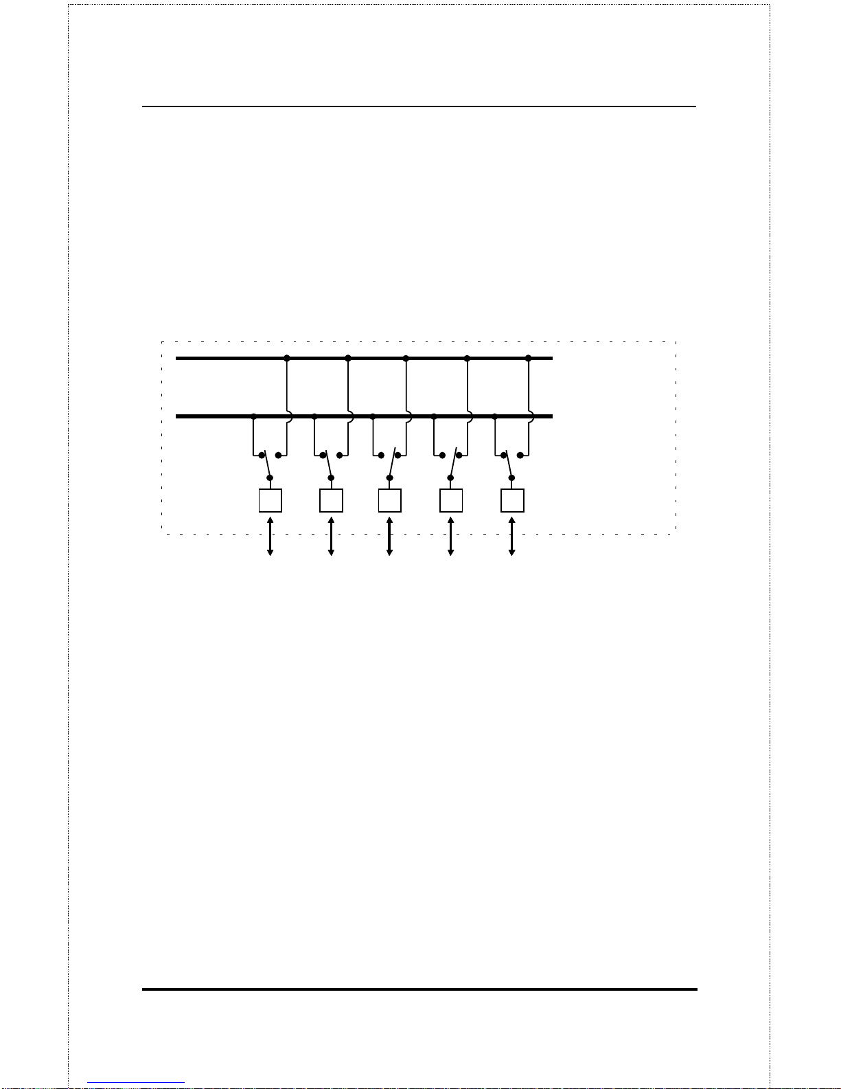
A dual-speed hub is actually two repeaters in one enclosure. The 10Mbps
repeater receives Ethernet transmissions from any of its ports, and retransmits them to all other ports operating at 10Mbps. Similarly, the 100Mbps
repeater retransmits Fast Ethernet transmissions from ports operating at
100Mbps to all other ports operating at the same speed.
10Mbps Repeater
100Mbps Repeater
NWay De te ction
RJ-45 Ports
100Mbps
Ethernet
Station
100Mbps
Ethernet
Station
10Mbps
Ethernet
Station
10Mbps
Ethernet
Station
100Mbps
Ethernet
Station
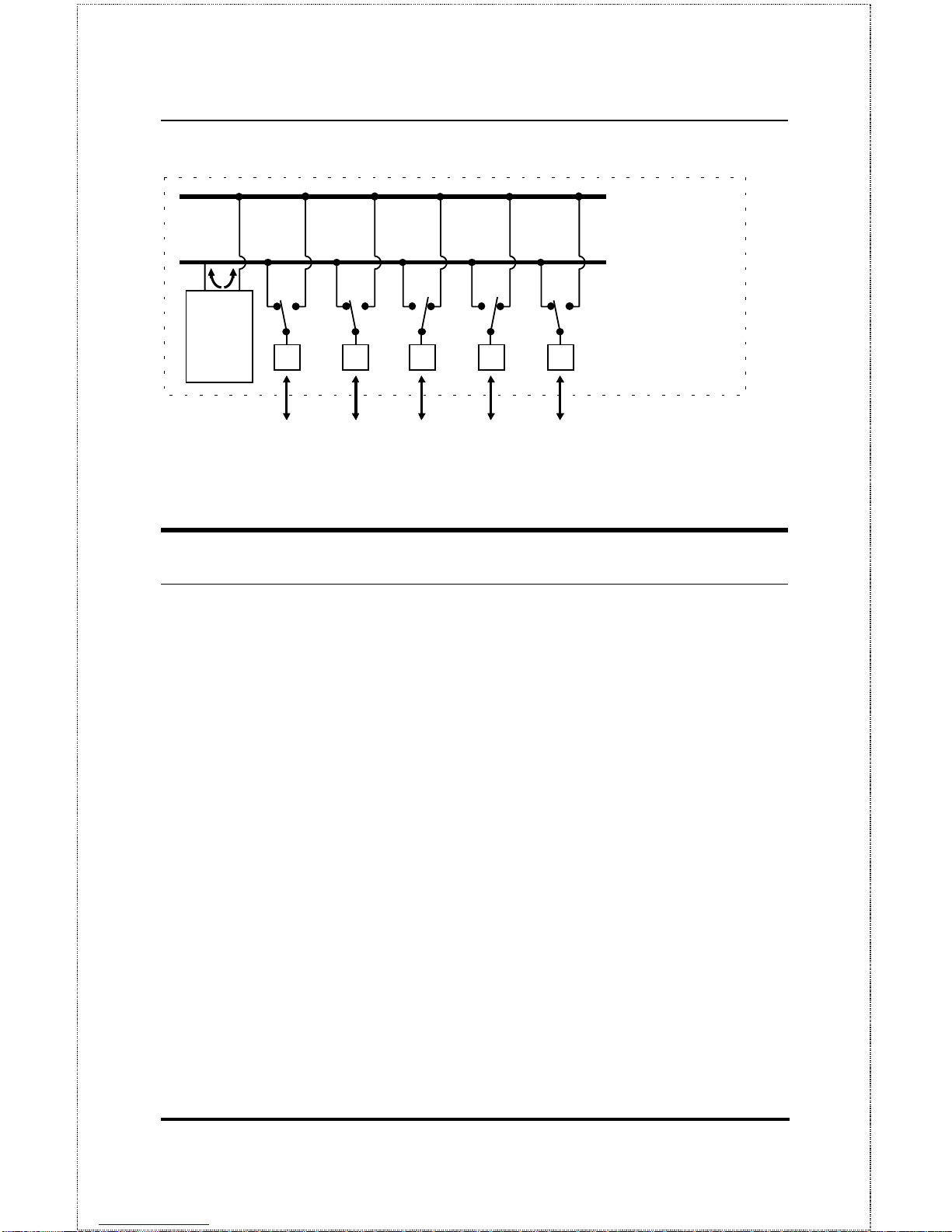
If there is a DFE-260S module, or a DFE-916x hub present in the stack, the
switching module will serve as a bridge between the two independent repeaters.
Dual-Speed Stackable Hubs User’s Guide
Introduction 5
10Mbps Repeater
100Mbps Repeater
NWay De te ction
RJ-45 Ports
100Mbps
Ethernet
Station
100Mbps
Ethernet
Station
10Mbps
Ethernet
Station
10Mbps
Ethernet
Station
100Mbps
Ethernet
Station
DFE-260s
Switch
Module
100BASE-TX Technology Overview
100Mbps Fast Ethernet Introduction
Computers today have become increasingly powerful, with the capability to
accommodate very sophisticated uses such as multimedia applications,
video-conferencing, and CAD/CAM. To utilize these technologically advanced applications more efficiently, there is also a growing demand for
faster networks that ca n ha ndle he avy ne t work traffi c .
Recognizing this need for greater bandwidth and lower latency, a variety of
technologi es such as FDDI, ATM, and Fast Et hernet (100Mbps) have be en
adopted by many vendors. Fast Ethernet technology stands out as the most
inexpensive and smoothest migration path for existing 10Mbps Ethernet
users in part because it doesn’t require a protocol translation when sharing
data with 10Mbps Ethernet.
Fast Ethernet is a relatively new standard specified by the IEEE 802. 3 LAN
committee. It is an extension of the 10Mbps Ethernet standard with the
ability to transmit and receive data at 100Mbps, while maintaining the
 Loading...