

Page 1

Page 2

.
_________________________________________________________________________________
Information in this document is subject to change without notice.
© 2011 D-Link Corporation. All rights reserved.
Reproduction in any manner whatsoever without the written permission of D-Link Corporation is strictly forbidden.
Trademarks used in this text: D-Link and the D-LINK logo are trademarks of D-Link Corporation; Mic rosoft and Windows are registered tradem arks
of Microsoft Corporation.
Other trademarks and trade names may be used in this document to refer to either the entities claiming t he marks and names or their products.
D-Link Corporation disclaims any proprietary interest in trademarks and trade names other than its own.
February 2011 P/N 651ES3200035G
Page 3

xStack® DES-3200 Series Layer 2 Ethernet Managed Switch WEB UI Reference Guide
ii
Table of Contents
Intended Readers ....................................................................................................................................................... viii
Typographical Conventions ........................................................................................................................................ viii
Notes, Notices, and Cautions ..................................................................................................................................... viii
Web-based Switch Configuration ................................................................................................. 9
Introduction ................................................................................................................................................................... 9
Login to Web Manager ............................................................................................................................................................... 9
Web-based User Interface ....................................................................................................................................................... 10
Web Pages .............................................................................................................................................................................. 11
Configuration ............................................................................................................................... 12
Device Information ...................................................................................................................................................... 13
System Information ..................................................................................................................................................... 13
Serial Port Settings ..................................................................................................................................................... 14
IP Address Settings .................................................................................................................................................... 15
IPv6 Address Settings ................................................................................................................................................ 17
IPv6 Route Settings .................................................................................................................................................... 18
IPv6 Neighbor Settings ............................................................................................................................................... 18
Port Configuration ....................................................................................................................................................... 19
Port Settings ............................................................................................................................................................................ 19
Port Description Settings.......................................................................................................................................................... 21
Port Error Disabled .................................................................................................................................................................. 21
Static ARP Settings .................................................................................................................................................... 22
User Accounts ............................................................................................................................................................ 23
System Log Configuration .......................................................................................................................................... 24
System Log Settings ................................................................................................................................................................ 24
System Log Server .................................................................................................................................................................. 24
DHCP Relay................................................................................................................................................................ 26
DHCP Relay Global Settings ................................................................................................................................................... 26
DHCP Relay Interface Settings ................................................................................................................................................ 29
DHCP Local Relay Settings ..................................................................................................................................................... 29
DHCP Auto Configuration Settings ............................................................................................................................. 30
MAC Address Aging Time .......................................................................................................................................... 30
Web Settings .............................................................................................................................................................. 31
Telnet Settings ............................................................................................................................................................ 31
Password Encryption .................................................................................................................................................. 31
CLI Paging Settings .................................................................................................................................................... 32
Firmware Information .................................................................................................................................................. 33
SNTP Settings ............................................................................................................................................................ 34
Time Settings ........................................................................................................................................................................... 34
Time Zone Settings .................................................................................................................................................................. 35
SMTP Settings ............................................................................................................................................................ 37
Page 4

xStack® DES-3200 Series Layer 2 Ethernet Managed Switch WEB UI Reference Guide
iii
SMTP Service Settings ............................................................................................................................................................ 37
SMTP Service .......................................................................................................................................................................... 38
MAC Notification Settings ........................................................................................................................................... 38
MAC Notification Global Settings ............................................................................................................................................. 38
MAC Notification Port Settings ................................................................................................................................................. 38
SNMP Settings ........................................................................................................................................................... 39
SNMP View Table .................................................................................................................................................................... 40
SNMP Group Table .................................................................................................................................................................. 41
SNMP User Table .................................................................................................................................................................... 42
SNMP Community Table.......................................................................................................................................................... 43
SNMP Host Table .................................................................................................................................................................... 44
SNMP Trap Configuration ........................................................................................................................................................ 45
RMON ...................................................................................................................................................................................... 45
Time Range Settings .................................................................................................................................................. 46
Single IP Management ............................................................................................................................................... 46
Single IP Settings ..................................................................................................................................................................... 48
Topology .................................................................................................................................................................................. 49
Tool Tips .................................................................................................................................................................................. 51
Right-Click................................................................................................................................................................................ 52
Menu Bar ................................................................................................................................................................................. 54
Firmware Upgrade ................................................................................................................................................................... 55
Configuration File Backup/Restore .......................................................................................................................................... 55
Upload Log File ........................................................................................................................................................................ 56
Gratuitous ARP ........................................................................................................................................................... 56
Gratuitous ARP Global Settings ............................................................................................................................................... 56
Gratuitous ARP Settings .......................................................................................................................................................... 57
ARP Spoofing Prevention Settings ............................................................................................................................. 58
PPPoE Circuit ID Insertion Settings ........................................................................................................................... 59
L2 Features ................................................................................................................................... 60
Jumbo Frame .............................................................................................................................................................. 60
VLANs ......................................................................................................................................................................... 61
Understanding IEEE 802.1p Priority ........................................................................................................................................ 61
VLAN Description ..................................................................................................................................................................... 61
IEEE 802.1Q VLANs ................................................................................................................................................................ 62
Q-in-Q VLANs .......................................................................................................................................................................... 65
802.1Q Static VLAN ................................................................................................................................................................. 67
Q-in-Q ......................................................................................................................................................................... 70
Q-in-Q Settings ........................................................................................................................................................................ 71
VLAN Translation Settings ....................................................................................................................................................... 72
802.1v Protocol VLAN ................................................................................................................................................ 72
802.1v Protocol Group Settings ............................................................................................................................................... 72
802.1v Protocol VLAN Settings ................................................................................................................................................ 74
VLAN Trunk Settings .................................................................................................................................................. 75
Page 5

xStack® DES-3200 Series Layer 2 Ethernet Managed Switch WEB UI Reference Guide
iv
GVRP Settings ............................................................................................................................................................ 76
Asymmetric VLAN Settings ......................................................................................................................................... 77
MAC-based VLAN Settings ........................................................................................................................................ 77
PVID Auto Assign Settings ......................................................................................................................................... 78
Port Trunking .............................................................................................................................................................. 78
LACP Port Settings ..................................................................................................................................................... 80
Traffic Segmentation ................................................................................................................................................... 81
Layer 2 Protocol Tunneling Settings ........................................................................................................................... 82
BPDU Attack Protection Settings ............................................................................................................................... 83
IGMP Snooping .......................................................................................................................................................... 84
IGMP Snooping Settings .......................................................................................................................................................... 84
IGMP Access Control Settings ................................................................................................................................................. 86
IGMP Snooping Multicast VLAN Settings ................................................................................................................................ 87
IP Multicast Profile Settings ..................................................................................................................................................... 88
Limited Multicast Range Settings ............................................................................................................................................. 90
Max Multicast Group Settings .................................................................................................................................................. 90
MLD Snooping Settings .............................................................................................................................................. 91
Port Mirror ................................................................................................................................................................... 94
Loopback Detection Settings ...................................................................................................................................... 94
Spanning Tree ............................................................................................................................................................ 96
STP Bridge Global Settings ..................................................................................................................................................... 98
STP Port Settings .................................................................................................................................................................... 99
MST Configuration Identification ............................................................................................................................................ 101
STP Instance Settings ........................................................................................................................................................... 102
MSTP Port Information .......................................................................................................................................................... 103
Forwarding & Filtering ............................................................................................................................................... 103
Unicast Forwarding Settings .................................................................................................................................................. 103
Multicast Forwarding Settings ................................................................................................................................................ 104
Multicast Filtering Mode ......................................................................................................................................................... 105
NLB Settings ............................................................................................................................................................. 106
LLDP ......................................................................................................................................................................... 106
LLDP Global Settings ............................................................................................................................................................. 107
LLDP Port Settings ................................................................................................................................................................ 108
LLDP Basic TLVs Settings ..................................................................................................................................................... 109
LLDP Dot1 TLVs Settings ...................................................................................................................................................... 110
LLDP Dot3 TLVs Settings ...................................................................................................................................................... 111
Ethernet OAM ........................................................................................................................................................... 112
Ethernet OAM Port Settings ................................................................................................................................................... 112
Ethernet OAM Event Configuration ........................................................................................................................................ 113
Connectivity Fault Management (CFM) .................................................................................................................... 114
CFM Settings ......................................................................................................................................................................... 116
CFM MA Settings ................................................................................................................................................................... 117
CFM MEP Settings ................................................................................................................................................................ 118
Page 6

xStack® DES-3200 Series Layer 2 Ethernet Managed Switch WEB UI Reference Guide
v
CFM Port Settings .................................................................................................................................................................. 120
CFM Loopback Settings ......................................................................................................................................................... 121
CFM Linktrace Settings .......................................................................................................................................................... 122
ERPS Settings .......................................................................................................................................................... 123
QoS ............................................................................................................................................. 125
Advantages of QoS ................................................................................................................................................................ 125
Understanding QoS ............................................................................................................................................................... 126
Bandwidth Control .................................................................................................................................................... 127
Traffic Control ........................................................................................................................................................... 128
Queue Bandwidth Control Sett ings .......................................................................................................................... 130
802.1p Default Priority .............................................................................................................................................. 131
802.1p User Priority .................................................................................................................................................. 131
QoS Scheduling Settings .......................................................................................................................................... 132
Priority Mapping ........................................................................................................................................................ 133
TOS Mapping ............................................................................................................................................................ 134
DSCP Mapping ......................................................................................................................................................... 135
Security ....................................................................................................................................... 136
Safeguard Engine ..................................................................................................................................................... 136
Trusted Host ............................................................................................................................................................. 138
IP-MAC-Port Binding ................................................................................................................................................ 138
IMP Binding Global Settings .................................................................................................................................................. 139
IMP Binding Port Settings ...................................................................................................................................................... 140
IMP Binding Entry Settings .................................................................................................................................................... 141
DHCP Snooping Entries ........................................................................................................................................................ 142
MAC Block List ....................................................................................................................................................................... 142
Port Security ............................................................................................................................................................. 142
Port Security Port Settings ..................................................................................................................................................... 142
Port Security FDB Entries ...................................................................................................................................................... 144
802.1X ....................................................................................................................................................................... 144
Understanding 802.1X Port-based and Ho st-based Network Access Control........................................................................ 147
Port-based Network Access Control ...................................................................................................................................... 147
Host-based Network Access Control ..................................................................................................................................... 148
802.1X Settings ...................................................................................................................................................................... 149
802.1X User ........................................................................................................................................................................... 150
Authentication RADIUS Server .............................................................................................................................................. 151
Guest VLAN Configuration ..................................................................................................................................................... 152
Guest VLAN ........................................................................................................................................................................... 153
Initialize Port(s) ...................................................................................................................................................................... 153
Reauthenticate Port(s) ........................................................................................................................................................... 154
SSL Settings ............................................................................................................................................................. 155
Download Certificate .............................................................................................................................................................. 156
Ciphersuite ............................................................................................................................................................................. 156
SSH ........................................................................................................................................................................... 157
Page 7

xStack® DES-3200 Series Layer 2 Ethernet Managed Switch WEB UI Reference Guide
vi
SSH Settings .......................................................................................................................................................................... 158
SSH Authmode and Algorithm Settings ................................................................................................................................. 158
SSH User Authentication Lists ............................................................................................................................................... 160
Access Authentication Control .................................................................................................................................. 161
Authentication Policy Settings ................................................................................................................................................ 162
Application Authentication Settings ........................................................................................................................................ 162
Authentication Server Group .................................................................................................................................................. 163
Authentication Server ............................................................................................................................................................. 164
Login Method Lists ................................................................................................................................................................. 165
Enable Method Lists .............................................................................................................................................................. 166
Local Enable Password Settings ............................................................................................................................................ 167
MAC-based Access Control...................................................................................................................................... 168
MAC-based Access Control Settings ..................................................................................................................................... 168
MAC-based Access Control Local Settings............................................................................................................................ 170
DoS Prevention Settings ........................................................................................................................................... 171
DHCP Server Screening Settings ............................................................................................................................. 172
DHCP Server Screening Port Settings ................................................................................................................................... 172
DHCP Offer Permit Entry Setting ........................................................................................................................................... 174
ACL ............................................................................................................................................. 175
ACL Configuration Wizard ........................................................................................................................................ 175
Access Profile List .................................................................................................................................................... 176
CPU Interface Filtering ............................................................................................................................................. 193
CPU Access Profile List ............................................................................................................................................ 193
ACL Finder ................................................................................................................................................................ 207
ACL Flow Meter ........................................................................................................................................................ 207
Monitoring .................................................................................................................................. 209
Cable Diagnostics ..................................................................................................................................................... 209
CPU Utilization .......................................................................................................................................................... 210
Port Utilization ........................................................................................................................................................... 211
Packet Size ............................................................................................................................................................... 212
Memory Utilization .................................................................................................................................................... 213
Packets ..................................................................................................................................................................... 214
Received (Rx) ........................................................................................................................................................................ 214
UMB_cast (Rx) ....................................................................................................................................................................... 216
Transmitted (Tx) ..................................................................................................................................................................... 217
Errors ........................................................................................................................................................................ 219
Received (RX) ........................................................................................................................................................................ 219
Transmitted (TX) .................................................................................................................................................................... 221
Port Access Control .................................................................................................................................................. 223
RADIUS Authentication .......................................................................................................................................................... 223
RADIUS Account Client ......................................................................................................................................................... 225
Authenticator State ................................................................................................................................................................ 227
Authenticator Statistics .......................................................................................................................................................... 228
Page 8

xStack® DES-3200 Series Layer 2 Ethernet Managed Switch WEB UI Reference Guide
vii
Authenticator Diagnostics ...................................................................................................................................................... 232
Browse ARP Table ................................................................................................................................................... 234
Browse VLAN ........................................................................................................................................................... 234
IGMP Snooping ........................................................................................................................................................ 234
Browse IGMP Router Port...................................................................................................................................................... 234
IGMP Snooping Group ........................................................................................................................................................... 235
IGMP Snooping Host ............................................................................................................................................................. 236
MLD Snooping .......................................................................................................................................................... 236
Browse MLD Router Port ....................................................................................................................................................... 236
MLD Snooping Group ............................................................................................................................................................ 237
LLDP ......................................................................................................................................................................... 237
LLDP Statistics System .......................................................................................................................................................... 237
LLDP Local Port Information .................................................................................................................................................. 238
LLDP Remote Port Information .............................................................................................................................................. 238
Ethernet OAM ........................................................................................................................................................... 239
Browse Ethernet OAM Event Log .......................................................................................................................................... 239
Browse Ethernet OAM Statistics ............................................................................................................................................ 239
Connectivity Fault Management ............................................................................................................................... 240
CFM Fault Table .................................................................................................................................................................... 240
CFM MP Table ....................................................................................................................................................................... 240
CFM Packet Counter ............................................................................................................................................................. 241
CFM MIPCCM Table .............................................................................................................................................................. 241
MAC-based Access Control Authentication State .................................................................................................... 242
Browse Session Table .............................................................................................................................................. 242
MAC Address Table .................................................................................................................................................. 243
System Log ............................................................................................................................................................... 244
Save and Tools ........................................................................................................................... 245
Save Configuration ................................................................................................................................................... 245
Save Log ................................................................................................................................................................... 246
Save All ..................................................................................................................................................................... 246
Configuration File Upload & Download ..................................................................................................................... 246
Upload Log File ......................................................................................................................................................... 247
Reset ......................................................................................................................................................................... 247
Ping Test ................................................................................................................................................................... 248
Download Firmware .................................................................................................................................................. 249
Reboot System ......................................................................................................................................................... 249
Appendix A Technical Specification ........................................................................................ 250
Appendix B System Log Entries ............................................................................................... 253
Appendix C RADIUS Attributes Assignment ........................................................................... 268
Appendix D Glossary ................................................................................................................. 271
Appendix E Warranty ................................................................................................................. 274
Page 9

xStack® DES-3200 Series Layer 2 Ethernet Managed Switch WEB UI Reference Guide
viii
Intended Readers
The DES-3200 Serie s User Manual contains information for set up and management of the Switch. This m anual is
intended for network managers familiar with network management concepts and terminology.
Typographical Conventions
Convention Description
[ ] In a command line, square brackets indicate an optional entry. For example: [copy
filename] means that optionally you can type copy followed by the name of the file. Do not
type the brackets.
Bold font Indicates a button, a toolbar icon, menu, or menu item. For example: Open the File menu
and choose Cancel. Used for emphasis. May also indicate system messages or prompts
appearing on your screen. For example: You have mail. Bold font is also used to
represent filenames, program names and commands. For example: use the copy
command.
Boldface Typewriter
Font
Indicates commands and responses to prompts that must be typed exactly as printed in
the manual.
Initial capital letter Indicates a window name. Names of keys on the keyboard have initial capitals. For
example: Click Enter.
Italics Indicates a window name or a field. Also can indicate a variables or parameter that is
replaced with an appropriate word or string. For example: type filename means that you
should type the actual filenam e instead of the word sho wn in italic.
Menu Name > Menu
Option
Menu Name > Menu Option Indicates the menu structure. Device > Port > Port
Properties means the Port Properties menu option under the Port menu option that is
located under the Device menu.
Notes, Notices, and Cautions
A NOTE indicates important information that helps you make better use of your device.
A NOTICE indic ates either pot ential damage to hardware or loss of data and te lls you
how to avoid the problem.
A CAUTION indicates a potential for property damage, personal injury, or death.
Page 10
xStack® DES-3200 Series Layer 2 Ethernet Managed Switch WEB UI Reference Guide
9
Section 1
Web-based Switch Configuration
Introduction
Login to Web Manager
Web-based User Interface
Web Pages
Introduction
All software functions of the S witc h c an be managed, configure d an d monitored via the embedded web-base d ( HTML)
interface. The Switch ca n be managed from remote statio ns anywhere on the network throug h a standard browser
such as Firefox, Microsoft Internet Explorer , Mozilla, or Netscape. The browser acts as a universal access tool and
can communicate directly with the Switc h using the H T T P protoc ol.
The Web-based m anagement module and the Consol e program (and Telnet) are diff erent ways to access the sam e
internal switching sof tware and conf igure it. Thus, al l settings encount ered in W eb-based managem ent are the sam e
as those found in the console program.
Login to Web Manager
To begin managing the Switch, s imply run the browser you have installed on your com puter and point it to the IP
address you have defined for the device. The URL in the address bar should read something like:
http://123.123.123.123, where the numbers 123 represent the IP address of the Switch.
NOTE: The Factory default IP address for the Switch is 10.90.90.90.
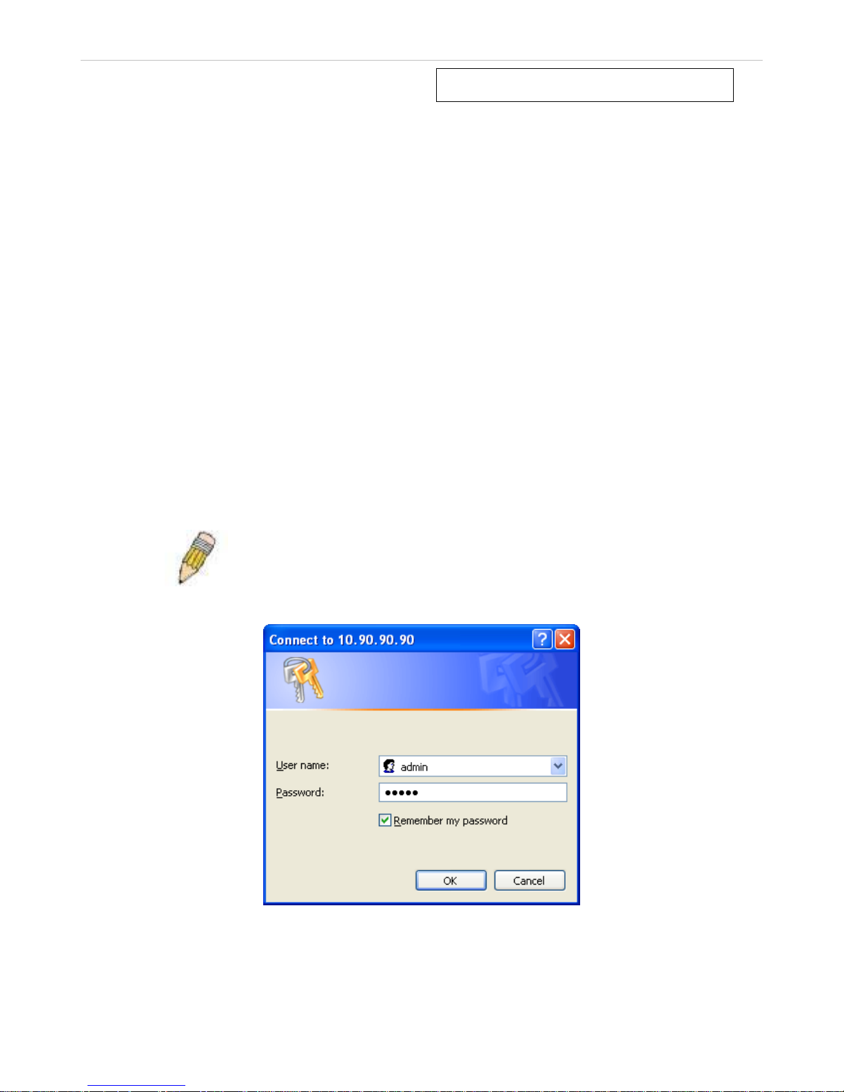
This opens the management module's user authentication window, as seen below.
Figure 1 - 1 Enter Network Password dialog
Enter “admin” in bot h the Us er Nam e and Pass word fields and click OK. T his will ope n the Web-based user interf ace.
The Switch management features available in the web-based manager are explained below.
Page 11
xStack® DES-3200 Series Layer 2 Ethernet Managed Switch WEB UI Reference Guide
10
Web-based User Interface
The user interface pr ovides access to various Switch conf iguration and management windows, allows you to view
performance statistics, and permits you to graphically monitor the system status.
Areas of the User Interface
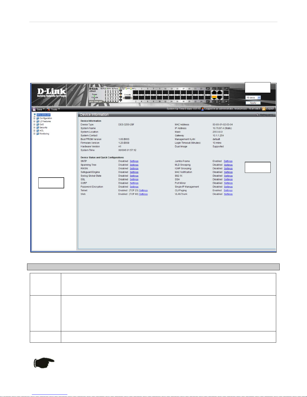
The figure below shows the user interface. The user interface is divi ded into three distinct areas as desc ribed in the
table.
Figure 1 - 2 Main Web-Manager page
Area Function
Area 1
Select the folder or window to be displayed. The folder icons can be opened to display the
hyperlinked window button s and subfol ders c ontai ned within t hem . Click the D -L ink logo to go t o the
D-Link website.
Area 2
Presents a graphical near real-time im age of the front panel of the Switch. T his area displays the
Switch's ports and expansion modules, showing port activity, dup
lex mode, or flow control,
depending on the specified mode.
Various areas of the graphic c an be selected for performing managem ent functions, including port
configuration.
Area 3
Presents switch information based on your selection and the entry of configuration data.
NOTICE: Any changes made to the Switch configuration during the current session must be saved in
the Save Configuration window (Save > Save Configuration) or use the command line interface
(CLI) command save config.
Area 1
Page 12

xStack® DES-3200 Series Layer 2 Ethernet Managed Switch WEB UI Reference Guide
11
Web Pages
When you connect to the m anagement m ode of the Switch wit h a Web browser , a login windo w is displayed. E nter a
user name and password to access the Switch's management mode.
Below is a list and description of the main folders available in the Web interface:
Configuration – Contains m ain windows concern ing Device Inform ation, S ystem Inform ation, Serial Port Sett ings, IP
Address, IPv6 Interface Settings, IPv6 Route Settings, IPv6 Neighbor Settings, Port Configuration, Static ARP
Settings, User Account s, System Log C onfiguration, DHCP Rela y, DHCP Auto Conf iguration Settin gs, MAC Address
Aging Time, W eb Settings, Telnet Set tings, Password Encr yption, CLI Pagin g Settings, Firm ware Information, SNT P
Settings, SMTP Setti ngs, MAC Notification Settin gs, SNMP Settings, Tim e Range Settings, Single IP Man agement,
Gratuitous ARP, ARP Spoofing Prevention Settings and PPPoE Circuit ID Insertion Settings.
L2 Features – Contains main windows concerning Jumbo Frame, 802.1Q Static VLAN, Q-in-Q, 802.1v Protocol
VLAN, VLAN Trunk Settings, GVRP Settings, Asymmetric VLAN Settings, MAC-based VLAN Settings, PVID Auto
Assign Settings, Port Trunking, LACP Port Settings, Traffic Segmentation, L2PT Settings, IGMP Snooping, MLD
Snooping Settings, Port Mirror, Loopback Detection Settings , Spanning Tree, Forwarding & F iltering, NLB Settings,
LLDP, Ethernet OAM, Connectivity Failure Management, and ERPS Settings.
QoS – Contains main windows concerning Bandwidth Control, Queue Bandwidth Control Settings, Traffic Control,
Queue Bandwidth Contr ol Settings, 802.1 P Default Priority, 802.1P User Priority, QoS Scheduling Sett ings, Priority
Mapping, TOS Mapping, and DSCP Mapping.
Security – Contains m ain windows conc erning Safeg uard Engine, T rusted Host, IP-MAC-Port Binding, Por t Security,
802.1X, SSL Settings, SSH, Access Authentic at io n Co ntr ol, M AC-b as ed Ac ces s Contr o l, Do S Pre ve nti on S etti ngs and
DHCP Server Screening.
ACL – Contains m ain windows concerning ACL Configuration W izard, Access Profile L ist, CPU Access Prof ile List,
ACL Finder, and ACL Flow Meter.
Monitoring – Contains m ain windows concerning C able Diagnostics, CPU Utilizati on, Port Utilization, Packet Size,
Memory Utilization, Pack ets, Errors, Port Access Control, Bro wse ARP Table, Browse VLAN, IGM P Snooping, MLD
Snooping, LLDP, Connectivity Failure Management, MAC-based Access Control Authentication State, Browse
Session Table, MAC Address Table, and System Log.
Save & Tools – Contains main windows concerning Save Configuration, Save Log, Save All, Configuration File
Upload & Download, Upload Log File, Reset, Ping Test, Download Firmware, and Reboot System.
NOTE: Be sure to configure the user name and password in the User
Accounts window (Configuration > User Accounts) before connecting
the Switch to the greater network.
Page 13

xStack® DES-3200 Series Layer 2 Ethernet Managed Switch WEB UI Reference Guide
12
Section 2
Configuration
Device Information
System Information
Serial Port Settings
IP Address Settings
IPv6 Interface Settings
IPv6 Route Settings
IPv6 Neighbor Settings
Port Configuration
Static ARP Settings
User Accounts
System Log Configuration
DHCP Relay
DHCP Auto Configuration Settings
MAC Address Aging Time
Web Settings
Telnet Settings
Password Encryption
CLI Paging Settings
Firmware Information
SNTP Settings
SMTP Settings
MAC Notification Settings
SNMP Settings
Time Range Settings
Single IP Management
Gratuitous ARP
ARP Spoofing Prevention Settings
PPPoE Circuit ID Insertion Settings
Page 14
xStack® DES-3200 Series Layer 2 Ethernet Managed Switch WEB UI Reference Guide
13
Device Information
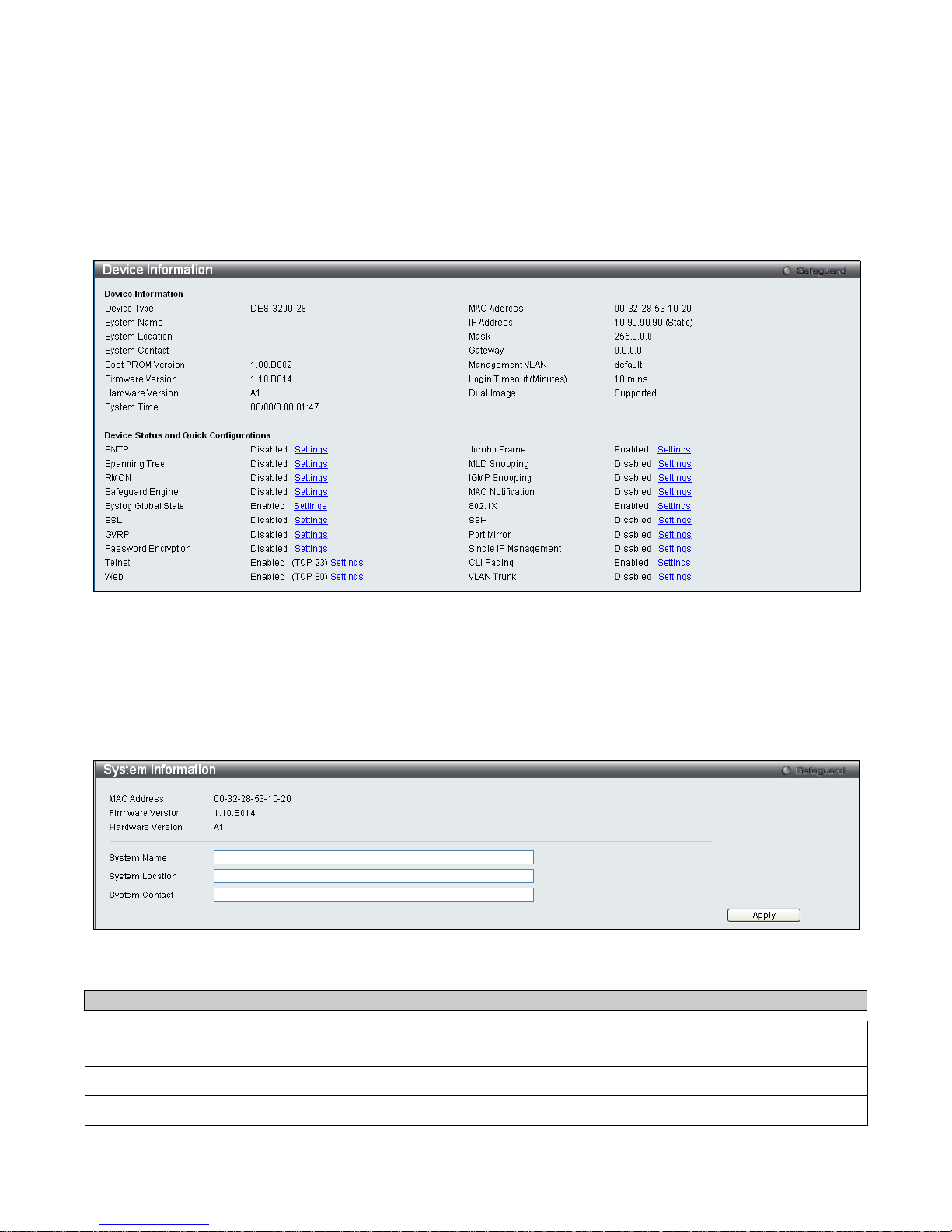
This window contai ns the m ain settings for all maj or functions on the Sw itch and appear s automaticall y when you log
on. To return to the Device Information windo w, click the DES-32 00 Series folder. T he Device Info rmation window
shows the Switch’s MAC Address (as signed by the factory and unchangeable) , the Boot PROM Version, Firmware
Version, the Hard war e Ver s ion, a nd ot her i nf ormation about different s etti ngs on t he S witc h. T his inf ormation is helpful
to keep track of PROM and f irmware updates and to obta in the Switch's MAC a ddress for entr y into another network
device's address table, if necessary. In add ition, this windo w displays the status of functions on t he Switch to quic kly
assess their current glo bal status. Som e f unctions are hyper -link ed to th eir conf igur ation windo w for eas y ac cess from
the Device Information window.
Figure 2 - 1. Device Information window
System Information
This window contains the System Inform ation details. The user may enter a System Name, System Location and
System Contact to aid in defining the Switch, to the user's preference. This window displays the MAC Address,
Firmware Version and Hardware Version.
Click Configuration > System Information to display the following window:
Figure 2 - 2. System Information window
The fields that can be configured are described below:
Parameter Description
System Name
Enter a system name for the Switch, if so desired. This name will identify it in the Switch
network.
System Location
Enter the location of the Switch, if so desired.
System Contact
Enter a contact name for the Switch, if so desired.
Click Apply to implement changes made.
Page 15
xStack® DES-3200 Series Layer 2 Ethernet Managed Switch WEB UI Reference Guide
14
Serial Port Settings
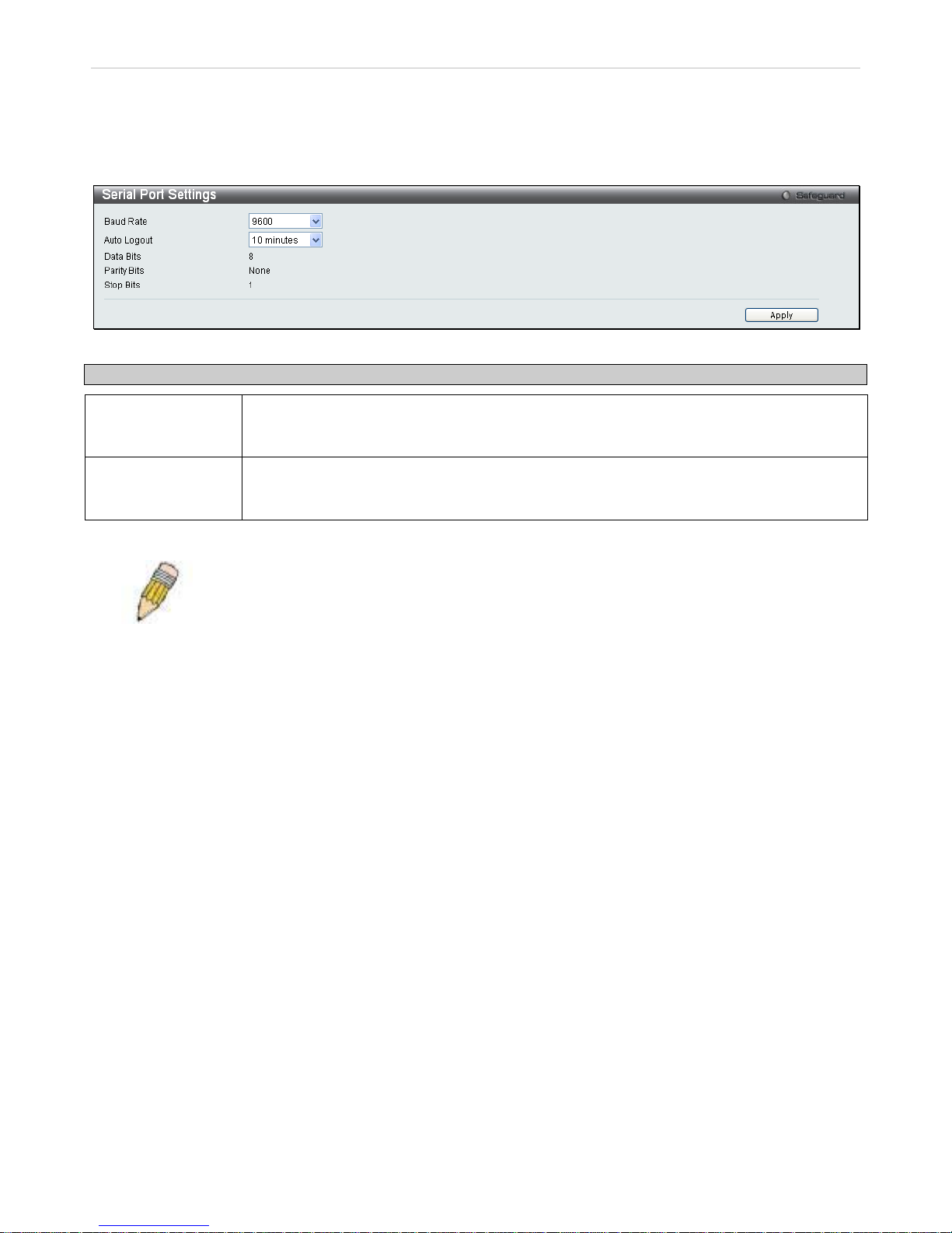
The following win dow allows the Baud Rate and t he Auto Logout to be changed as well as containing inform ation
about the Serial Port Settings.
Click Configuration > Serial Port Settings to display this window:
Figure 2 - 3. Serial Port Settings window
Parameter Description
Baud Rate
This field specifies the baud rate for the serial port on the Switch. There are four possible
baud rates to choose from , 9600, 19200, 38400 and 115200. For a conn ection to the Switch
using the CLI interface, the baud rate must be set to 9600, which is the default setting.
Auto Logout
Select the logout tim e used for the console interf ac e. T his aut omatically logs the u ser out af ter
an idle period of time, as d ef ined. C hoos e f r om the following options : 2 Minutes, 5 Minutes, 1 0
Minutes, 15 Minutes or Never. The default setting is 10 minutes.
Click Apply to implement changes made.
NOTE: If a user configures the ser ial port’s baud r ate, the baud rate will take effec t and save
immediately.
Page 16

xStack® DES-3200 Series Layer 2 Ethernet Managed Switch WEB UI Reference Guide
15
IP Address Settings
The IP address ma y initially be se t using the console interface prior to connecting to it through the Ethern et. If the
Switch I P a ddress has not yet been ch anged, read th e intr oductio n of the DES-3200 Series CLI Reference Manual for
more information.
Click Configuration > IP Address Settings to display the following window:
Figure 2 - 4. IP Address Settings window
To manually assign the Switch's IP address, subnet mask, and default gateway address:
1. Click Static at the top of the window.
2. Enter the appropriate IPv4 Address and Sub net Mas k.
3. To access the Switch from a different subnet from the one it is installed on, enter the IP address of the
Gateway. If the Switch will be managed from the subnet on which it is installed, leave the def ault address
(0.0.0.0) in this field.
4. If no VLANs have been previously configured on the Switch, you can use the default Management VLAN
Name. The default VLAN contains all of the Switch ports as members. If VLANs have been previously
configured on the Switch, t he Management VLAN Nam e of the VLAN that contains the port conn ected to the
management station will have to be entered to ac c ess the Switch .
5. Use the drop-down Interface Admin State menu to select Enabled if it has not already been done.
NOTE: The Switch's factory default IP address is 10.90.90.90 with a
subnet mask of 255.0.0.0 and a default gateway of 0.0.0.0.
To use the BOOTP or DHCP protocols to assign the Switch an IP address, subnet mask, and default gateway
address, select either BOOTP or DHCP.
Page 17

xStack® DES-3200 Series Layer 2 Ethernet Managed Switch WEB UI Reference Guide
16
The IP Address Settings options are:
Parameter Description
Static
Allows the entry of an IPv4 ad dress, Subnet Mas k, and a Default Gate way for th e Switch. T hese
fields should be of the form xxx.xxx .xxx.xxx, where e ach x xx is a number (represented in d ecim al
form) between 0 and 2 55. This addr ess should be a unique addres s on the n etwork as signed for
use by the network administrator.
DHCP
The Switch will send o ut a DHCP broadcas t request when it is powered up. Th e DHCP protocol
allows IP address es, network masks, and default g ateways to be assigned b y a DHCP server. If
this option is set, the Swit ch will first look for a DHCP server to provide it with this information
before using the default or previously entered settings.
BOOTP
The Switch will send out a BOOTP broadcast request when it is powered up. The BOOTP
protocol allows IP addres ses, network masks , and default gateways to be assigned b y a central
BOOTP server. If this optio n is set, t he Switc h will f irst look for a BOOTP s erver t o provide it with
this information before using the default or previously entered settings.
IP Interface
The current IP Interface being assigned an IP address on this window.
Management
VLAN Name
This allows the entry of a VLAN Name from which a management station will be allowed to
manage the Switch us in g T C P/I P (i n-band via web manager or Telnet). Mana gem ent s ta tio ns th at
are on VLANs other than the one enter ed here will not be able to manage the Switch in-band
unless their IP addresses are entered in the Securit y IP Management window. If VLANs have
not yet been configured f or the Switc h, the default VLAN contains all of the S witch's ports . There
are no entries in th e Security IP Mana gement table, by def ault, so any manage ment station that
can connect to the Switch can access the Switch until a management VLAN is specified or
Management Station IP Addresses are assigned.
Interface Admin
State
Toggle between Enabled and Disabled. This mus t be set to Enabled when setting an I P address
on this window.
IPv4 Address
Enter the desired IPv4 address to be set. The default address is 10.90.90.90.
Subnet Mask
A Bitmask that determines the extent of the subn et that the Switch is o n. Should be of the f orm
xxx.xxx.xxx.xxx , where each xxx is a number (repres ented in decimal) between 0 and 255. The
value should be 255.0.0.0 for a Class A network, 255.255.0.0 for a Class B network, and
255.255.255.0 for a Class C network, but custom subnet masks are allowed.
Gateway
IP address that determ ines where packets with a destination a ddress outside the current subnet
should be sent. This is usually the ad dress of a rout er or a host ac ting as an IP gate way. If your
network is not part of an intranet, or you do not wan t the Switch to be accessible out side your
local network, you can leave this field unchanged.
DHCP Option 12
State
Use to enable or disable DHCP Option 12.
DHCP Option 12
Host Name
Type the name of the host used for Option 12. Up to 63 characters are allowed.
Click Apply to allow changes to take effect.
Page 18
xStack® DES-3200 Series Layer 2 Ethernet Managed Switch WEB UI Reference Guide
17
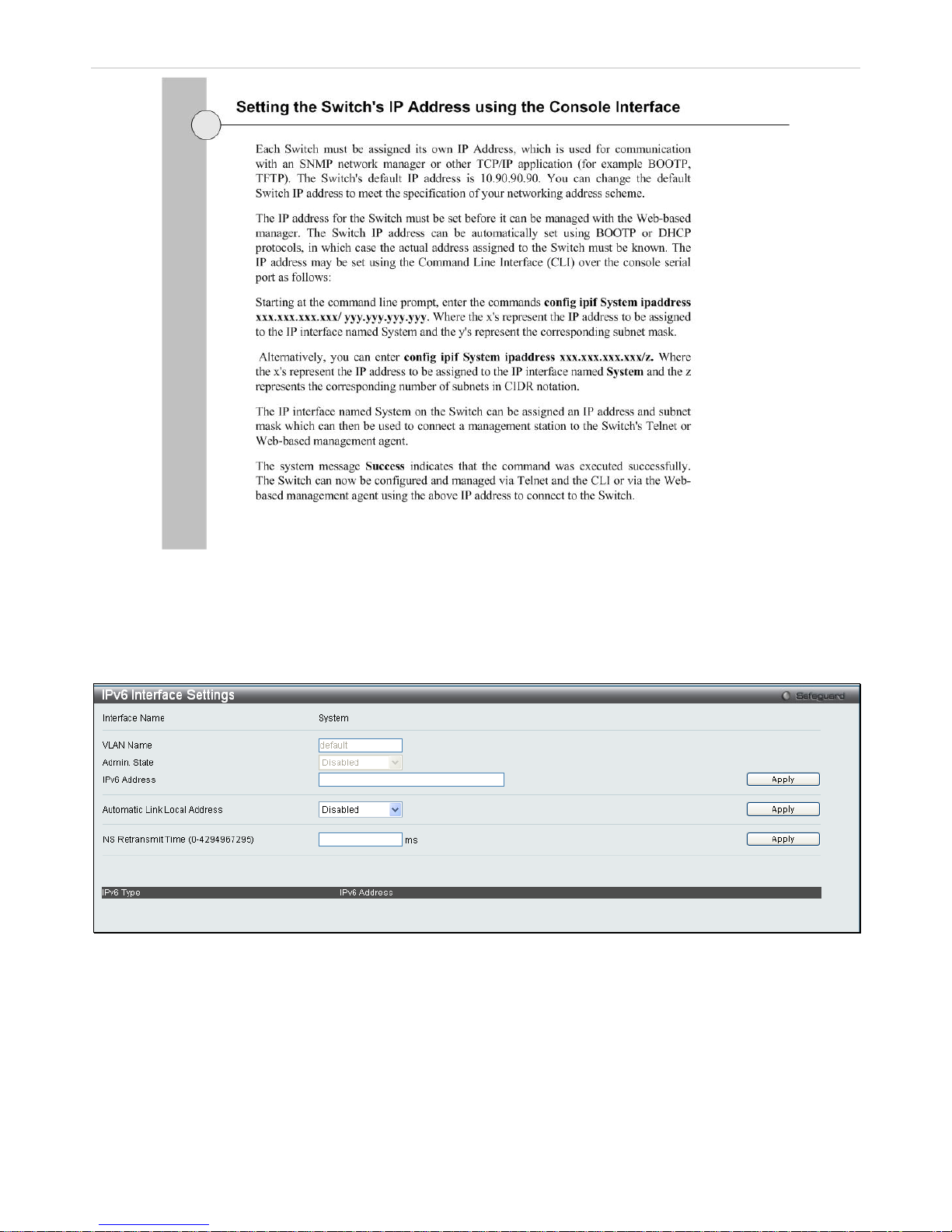
IPv6 Address Setti ngs
Users can display the Switch’s current IPv6 interface settings.
To view the following window, click Configuration > IPv6 Interface Settings:
Figure 2 - 5. IPv6 Interface Settings window
To configure IPv6 inter face settings, e nter an IPv6 Addr ess and c lick Apply. The new entr y will app ear in t he table at
the bottom of the window.
After making the desired changes, click the Apply button.
The following parameters may be configured or viewed:
Page 19
xStack® DES-3200 Series Layer 2 Ethernet Managed Switch WEB UI Reference Guide
18
Parameter Description
Interface Name
The name of the IPv6 interface being displayed or modified.
VLAN Name
Display the VLAN name of the IPv6 interface.
Admin. State
Display the current administrator state.
IPv6 Address
Enter the IPv6 address of the interface to be modified.
Automatic Link
Local Address
Toggle between Enabled and Disabled. Enabling this i s helpf ul when no external sour c e of net work
addressing information is available.
NS Retransmit
Time (0-
4294967295)
Enter a value between 0 and 4294967295. This is the neighbor solicitation’s retransmit timer in
milliseconds. The default is zero.
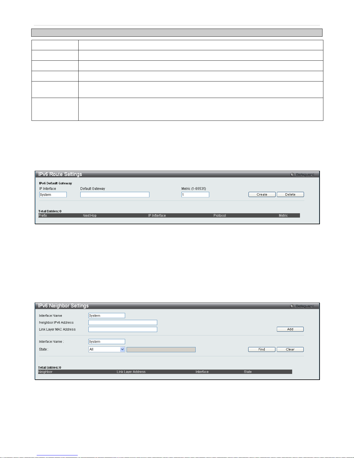
IPv6 Route Settings
The user can configure the Switch’s IPv6 Route Table.
To view the following window, click Configuration > IPv6 Route Settings:
Figure 2 - 6. IPv6 Route Settings window
Enter an IP Interfac e, an IPv6 addres s in the Default Gateway fiel d and then cli ck the Create butto n. In addition, the
Metric can be enter ed between 1 and 65535. The new I Pv6 route will be displ ayed in the table at th e bottom of the
window.
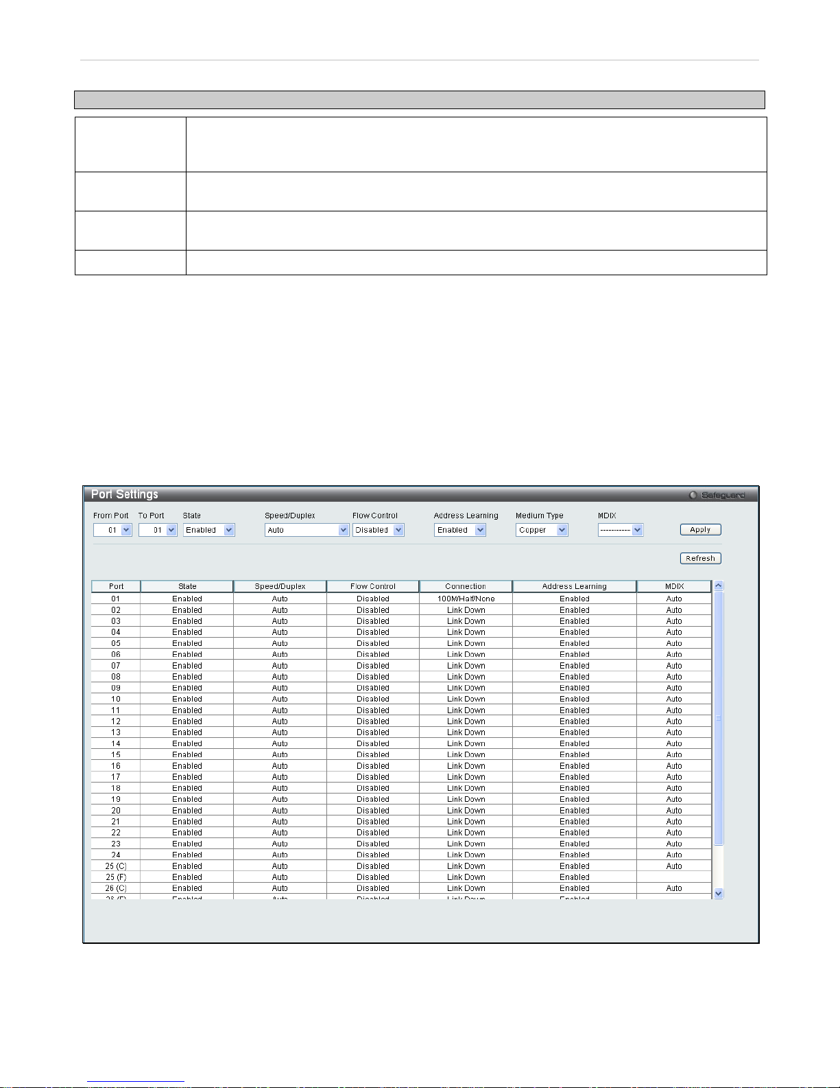
IPv6 Neighbor Settings
The user can configure the Switch’s IPv6 neighbor settings. The Switch’s current IPv6 neighbor settings will be
displayed in the table at the bottom of this window.
To view the following window, click Configuration > IPv6 Neighbor Settings:
Figure 2 - 7. IPv6 Neighbor Settings window
Enter the Interface Name, Neighbor IPv6 Address, and the Link Layer MAC Address and then click the Add button.
To look for an IPv6 Neigh bor Settings table entry, enter th e Interface Name, select the desir ed State (All, Address,
Static, or Dynamic) in the middle section of this window, and then click the Find button.
To delete all the entries being displayed on the table at the bottom of this window, click the Clear button.
Page 20
xStack® DES-3200 Series Layer 2 Ethernet Managed Switch WEB UI Reference Guide
19
The following parameters may be configured or viewed:
Parameter Description
Interface Name
Enter the name of the IPv6 neighbor . To search for all the current int erfaces on the Switch, go to
the second Interface Nam e field in th e middle part of t he window, tick the All check box, and then
click the Find button.
Neighbor IPv6
Address
Enter the neighbor IPv6 address.
Link Layer MAC
Address
Enter the link layer MAC address.
State Use the drop-down menu to select All, Address, Static, or Dynamic.
Port Configuration
This section contains information for configuring various attributes and properties for individual physical ports,
including port speed and flow control.
Port Settings
Various port settings, including State, Spe ed/Duplex, Flow Contro l, Address Learning, Medium Type, and MDIX can
be configured on the Switch.
To view the following window, click Configuration > Port Configuration > Port Settings:
Figure 2 - 8. Port Settings window
To configure switch ports , choose the port or sequential range of por ts using the From Port and To Port pull-down
menus. Use the remaining pull-down menus to configure the parameters described below:
Page 21

xStack® DES-3200 Series Layer 2 Ethernet Managed Switch WEB UI Reference Guide
20
Parameter Description
From Port/To
Port
Use the pull-down menus to select the port or range of ports to be configured.
State
Toggle this field to either enable or disable a given port or group of ports.
Speed/Duplex
Toggle the Speed/Duplex field to either select the speed and duplex/half-duplex state of the port.
Auto denotes auto-negoti ation between 10 and 100 Mbps devices , in full- or half-duplex. The
Auto s etting allows th e port to autom atically determ ine the fastes t settings the d evice the por t is
connected to can handle, and then to us e those settin gs. The other opt ions are Auto, 10M Half,
10M Full, 100M Half and 100M Full, 1000M Full_Master, 1000M Full_Slave and 1000M Full.
There is no automatic adjustment of port settings with any option other than Auto.
The Switch allows the user to configure two types of gigabit connections; 1000M/Full_M and
1000M/Full_S. Gigabit connections only support full duplex connections and take on certain
characteristics that are different from the other choices listed.
The 1000M Full_Master and 1000M Full_Slave parameters refer to connections running a
1000BASE-T cable for connec tio n be t we en th e S witch port and other devic e capable of a gigabit
connection. The m aster setting (1000 M Full_Master) will allow the port to a dvertise capabilities
related to duplex, speed and physical layer type. The master setting will also determine the
master and slave relations hip between the two connected physical layers. This relationship is
necessary for establishi ng the tim ing control b etween the t wo ph ysical layers. T he timing c ontrol
is set on a master physical layer by a local sour ce. The slave setti ng (1000M Full_Slave) uses
loop timing, where the timing comes from a data stream received from the master. If one
connection is set for 1000M F ull_Mas ter, t he other s ide of the conn ection m us t be set for 1000M
Full_Slave. Any other configuration will result in a link down status for both ports.
Flow Control
Displays the flow contr ol scheme used for the various por t configurations. Ports configured f or
full-duplex use 802.3x flow control, half -duplex ports use backpressure flow control, a nd Auto
ports use an automatic selection of the two. The default is Disabled.
Address
Learning
When Enabled, desti nat io n and sour c e M AC a ddres s e s are automatically listed in the f or ward ing
table. The default setting is Enabled.
Medium Type
This applies only to th e Combo ports. If configuring the Com bo ports this defines the type of
transport medium us ed. SFP ports should be set at Fiber and the Combo 1000BASE-T ports
should be set at Copper.
MDIX This can be specified as Auto, Normal, or Cross. In Normal state, the port is in MDIX mode and
can be connec ted to a PC NIC using a straight cable. If it is in Cross state, the port is in MDI
mode, and can be connec ted to a port (in MDIX mode) on another switch through a straight
cable.
Click Apply to implement the new settings on the Switch.
Page 22
xStack® DES-3200 Series Layer 2 Ethernet Managed Switch WEB UI Reference Guide
21
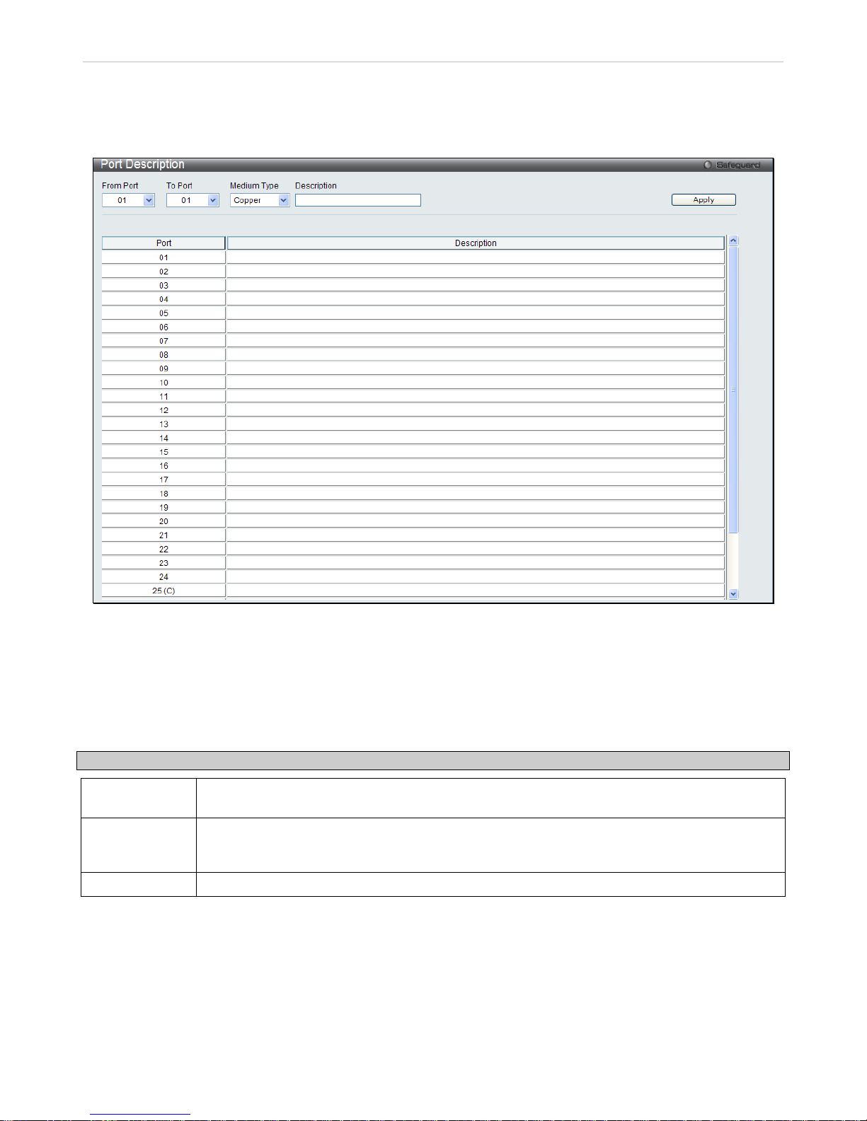
Port Description Settings
The Switch supports a port description feature where the user may name various ports on the Switch.
To view the following window, click Configuration > Port Configuration > Port Description Settings:
Figure 2 - 9. Port Description Settings window
Use the From Port and To Port pull-down menus to choose a port or range of ports to describe, and then enter a
description of the port(s).
The Medium Type applies only to the Combo ports. If configuring the Combo ports this defines the type of transport
medium used. SFP ports should be nominated Fiber and the Combo 1000BASE-T ports should be nominated Copper.
The result will be displayed in the appropriate switch port number slot (C for copper ports and F for fiber ports).
The following parameters can be configured:
Parameter Description
From Port/To
Port
Use the pull-down menus to select the port or range of ports to be configured.
Medium Type
This only applies to the Combo ports. If configuring the Combo ports, this defines the t ype of
transport medium used. SFP ports should be set at Fiber and the Combo 1000BASE-T ports
should be set at Copper.
Description
The description of the the ports.
Click Apply to implement the new settings on the Switch.
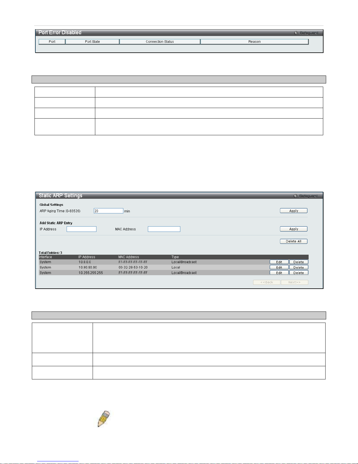
Port Error Disabled
The following window will display inform ation about ports that have had their connection st atus disabled for reasons
such as STP loopback detection or link down status.
To view this window, click Configuration > Port Configuration > Port Error Disabled:
Page 23
xStack® DES-3200 Series Layer 2 Ethernet Managed Switch WEB UI Reference Guide
22
Figure 2 - 10. Port Error Disabled window
The following parameters are displayed:
Parameter Description
Port
Displays the port that has been error disabled.
Port State
Describes the current running state of the port, whether Enabled or Disabled.
Connection Status
This field will read the uplink status of the individual ports, whether Enabled or Disabled.
Reason
Describes the reason why the port has been error-disabled, such as a STP loopback
occurrence.
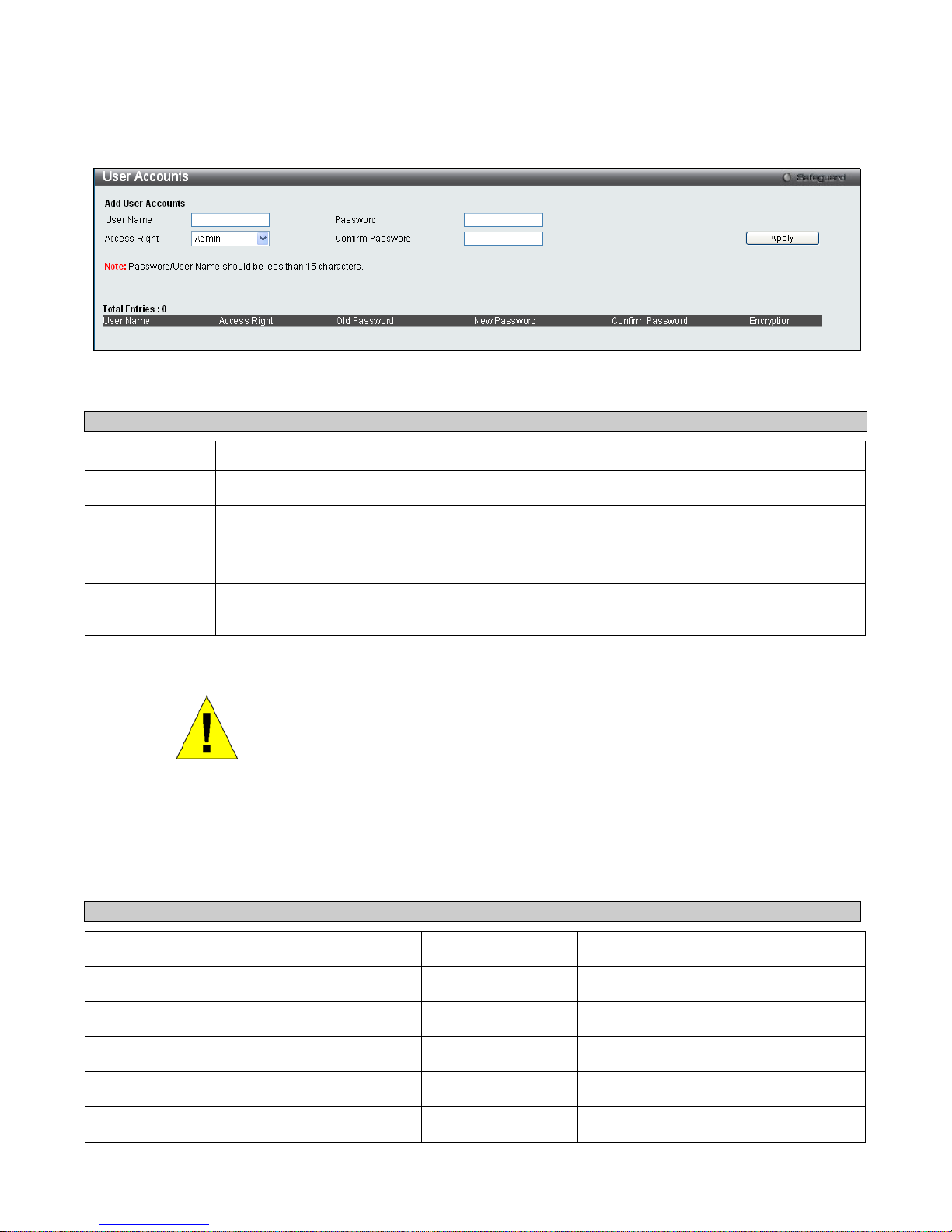
Static ARP Settings
The Address Resolution Pr otocol ( ARP) is a T CP/I P pr otocol that c onverts IP addr ess es into ph ysical ad dress es. T his
table allows network m anagers to view, define, m odify and delete ARP infor mation for specif ic devices. Static entr ies
can be defined in the ARP Table. When static entries are defined, a permanent entry is entered and is used to
translate IP address to MAC addresses.
To view this window, click Configuration > Static ARP Settings
Figure 2 - 11. Static ARP Settings window
The following fields can be set:
Parameter Description
ARP Aging Time
(0-65535)
The user may globally set the maximum amount of time, in seconds, that an Address
Resolution Protocol (ARP) entry can remain in the Switch’s ARP table, without being
accessed, before it is dropped from the table. The value may be set in the range of 0 to
65535 seconds, with a default setting of 20 seconds.
IP Address
The IP address of the ARP entry.
MAC Address
The MAC address of the ARP entry.
After entering the IP Addre ss and MAC Addres s of the Static ARP entr y, click Apply to implem ent the new entr y. To
completely clear the Static ARP Settings, click the Delete All button. To modify a static ARP entry, click the
corresponding Edit button in the table. To delete a static ARP entry, click the corresponding Delete button in the table.
NOTE: The Switch supports up to 255 static ARP entries.
Page 24
xStack® DES-3200 Series Layer 2 Ethernet Managed Switch WEB UI Reference Guide
23
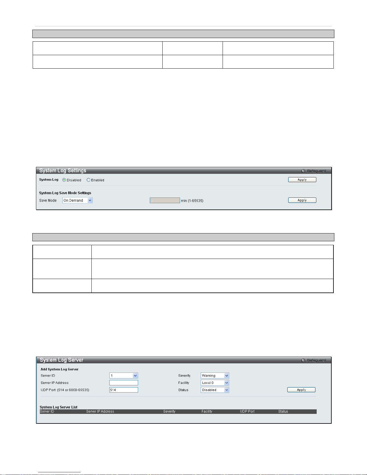
User Accounts
Use this window to control user privileges, create new users, and view existing User Accounts.
To view this window, click Configuration > User Accounts:
Figure 2 - 12. User Accounts window
The following fields can be set:
Parameter Description
User Name
The name of the user, an alphanumeric string of up to 15 characters.
Password
Enter a password for the new user.
Access Right There are two levels of user privi leges, Admin and User. Some features and sel ections available
to users with Admin privileges may not be available to those with User level privileges.
(Table 2 - 1 below summarizes Admin and User level privileges)
Confirm
Password
Retype the new password.
To add a new user, ent er the appropriate information and c lick Apply. To modif y or delete an existing us er, click on
the Edit button for that user.
NOTICE: In case of lost p asswords or password cor ruption, please refer to the
“Password Recovery Procedure” Appendix in the DES-3200 Series CLI
Reference Manual which wil l guide you thro ugh the s teps necessar y to resolve
this issue.
Admin and User Privileges
There are two levels of user privileges, Admin and User. Some menu selections available to users with Admin
privileges may not be available to those with User privileges.
The following table summarizes the Admin and User privileges:
Management Admin User
Configuration Yes Read-only
Network Monitoring Yes Read-only
Community Strings and Trap Stations Yes Read-only
Update Firmware and Configuration Files Yes No
System Utilities Yes No
Factory Reset Yes No
Page 25
xStack® DES-3200 Series Layer 2 Ethernet Managed Switch WEB UI Reference Guide
24
User Account Management
Add/Update/Delete User Accounts Yes No
View User Accounts Yes No
Table 2 - 1. Admin and User Privileges
System Log Configuration
This section contains information for configuring various attributes and properties for System Log Configurations,
including System Log Settings and System Log Host.
System Log Settings
This window allows the user to enable or disable the System Log and specify the System Log Save Mode Settings.
To configure the system log settings, click Configuration > System Log Configura tion > System Log Settings
Figure 2 - 13. System Log Settings window
The following parameters can be set:
Parameter Description
System Log
Use the radio buttons to either enable or disable the system log feature.
Save Mode
Use this drop-down m enu to choose the m ethod that will trigger a log entry. Choose among
On Demand, Time Interval, and Log Trigger.
min (1-65535)
Enter a time interval, in minutes, for which a log entry is to be made.
To modify the system log settings on this window, enter the appropriate information and click Apply.
System Log Server
The Switch can send Syslog messages to up to four designated servers using the System Log Server.
To configure the system log settings, click Configuration > System Log Configura tion > System Log Server:
Figure 2 - 14. System Log Server window
The following parameters can be set:
Page 26

xStack® DES-3200 Series Layer 2 Ethernet Managed Switch WEB UI Reference Guide
25
Parameter Description
Server ID
Syslog server settings index (1-4).
Severity
This drop-down m enu allo w s you to s e lect the level of m ess ages t hat wil l be s en t. The options
are Warning, Informational, and All.
Server IP Address
The IP address of the Syslog server.
Facility
Some of the operati ng system daemons and pr ocesses have been assign ed Facility values.
Processes and daemons that have not been exp licitly assigned a Facility may use an y of the
"local use" facilities or they ma y use the "user-level" Facility. Those Faci lities that have bee n
designated are shown i n the f ollowin g: Bold font indic ates th e fac ility valu es tha t the Switch is
currently employing.
Numerical Facility Code Numerical Facility Code
0
1
2
3
4
5
7
8
9
10
11
kernel messages
user-level messages
mail system
system daemons
security/authorization messages
messages generated intern a l ly by
syslog line printer subsystem
network news subsystem
UUCP subsystem
clock daemon
security/authorization messages
FTP daemon
12
13
14
15
16
17
18
19
20
21
22
23
NTP subsystem
log audit
log alert
clock daemon
local use 0 (local0)
local use 1 (local1)
local use 2 (local2)
local use 3 (local3)
local use 4 (local4)
local use 5 (local5)
local use 6 (local6)
local use 7 (local7)
UDP Port
(514 or 6000-65535)
Type the UDP port number used for sending Syslog messages. The default is 514.
Status Choose Enabled or Disabled to activate or deactivate.
To add a new entry, enter the appropriate information and click Apply.
Page 27
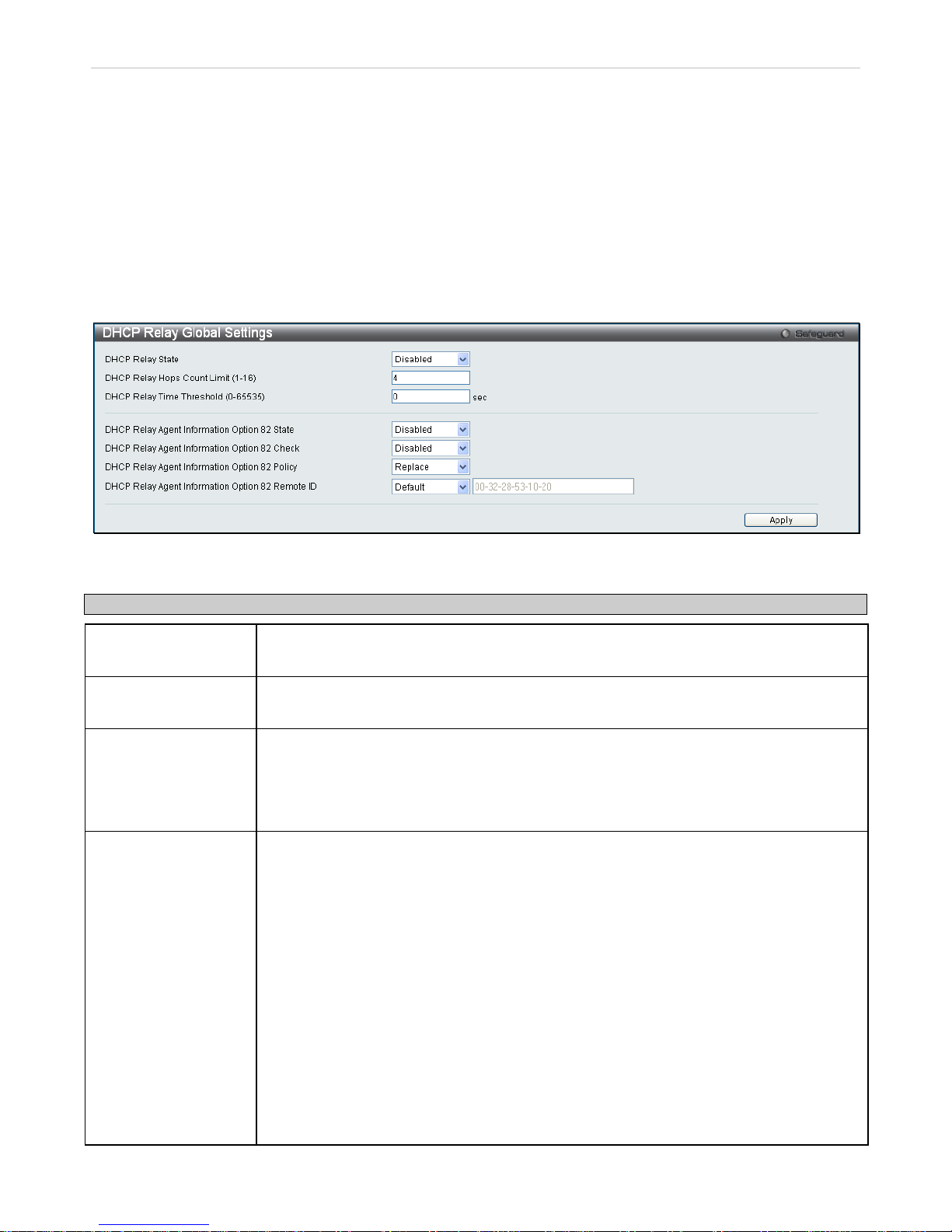
xStack® DES-3200 Series Layer 2 Ethernet Managed Switch WEB UI Reference Guide
26
DHCP Relay
The relay hops count lim it allows the maximum number of hops (routers) that the DHCP m essages can be relayed
through to be set. If a packet’s hop c ount is equal to or more than the hop cou nt limit, the packet is dropped. The
range is between 1 and 16 hops, with a default value of 4. The relay time threshold sets the minimum time (in
seconds) that the Switch will wait before f orwarding a BOOT REQUEST pac ket. If the valu e in the seconds field of the
packet is less than the re lay time t hreshold, the pack et will be dro pped. T he range is be tween 0 and 65,535 seconds,
with a default value of 0 seconds.
DHCP Relay Global Settings
To enable and configur e DHCP Relay Global Sett ings on the Switch, c lick Configuration > DHC P Relay > DHCP
Relay Global Settings:
Figure 2 - 15. DHCP Relay Global Settings window
The following fields can be set:
Parameter Description
DHCP Relay State This field can be toggled between Enabled and Disabled using the pull-down menu. It is
used to enable or disable the DHCP Relay service on the Switch. The default is Disabled
DHCP Relay Hops
Count Limit (1-16)
This field allows an entry betwee n 1 and 16 to define the m aximum num ber of router hops
DHCP messages can be forwarded across. The default hop count is 4.
DHCP Relay Time
Threshold (0-65535)
Allows an entry between 0 and 65535 seconds, and defines the maximum time limit for
routing a DHCP pac ket. If a value of 0 is entered, the S witch will not process t he value in
the seconds field of the BO OTP or DH CP packet. If a non-zero value is ent ered, the S witch
will use that value, along with the hop count to determine whether to forward a given
BOOTP or DHCP packet.
DHCP Relay Agent
Information Option 82
State
This field can be toggled between Enabled and Disabled using the pull-down menu. It is
used to enable or disabl e t he DHCP Agent Inform ation O pti on 8 2 on t he S witch. T he default
is Disabled.
Enabled – When this field is toggled to Enabled the relay agent will insert and remove
DHCP relay information (o ption 82 field) in messages bet ween DHCP servers and clients.
When the relay agent rec eives th e DH C P req ues t , i t a dds the opt ion 82 inf ormation, and the
IP address of the relay agent (if the relay agent is configured), to the packet. Once the
option 82 inform ation has been added to the pack et it i s sent on to the DHC P ser ver. W hen
the DHCP server rece ives t he pac ket , if the ser ver is c apable of opti on 82, it can im plement
policies like restricting the num ber of IP addresses that can be ass igned to a sin gle remote
ID or circuit ID. T hen the DHCP server ec hoes the option 82 f ield in the DHCP reply. The
DHCP server unicasts the repl y to the back to the relay age nt if the request was rela yed to
the server by the relay agent. The switch verifies that it originally inserted the option 82
data. Finally, the rela y agent removes the option 82 field and forwards the pa cket to the
switch port that connects to the DHCP client that sent the DHCP request.
Disabled - If the f ield is to g gle d to Disabled t he re lay agent will not insert and r emove DHCP
relay information (optio n 82 field) in m essages betwee n DHCP servers an d clients, and the
Page 28

xStack® DES-3200 Series Layer 2 Ethernet Managed Switch WEB UI Reference Guide
27
check and policy settings will have no effect.
DHCP Relay Agent
Information Option 82
Check
This field can be toggled between Enabled and Disabled using the pull-down menu. It is
used to enable or disable the S witches ab ility to c heck the valid ity of t he pack et’s opt ion 82
field.
Enabled – W hen the field is toggled to Enable, the r elay agent will ch eck the validit y of the
packet’s option 82 f ield . If t he switch receives a pac ket that contains the op tio n-82 field from
a DHCP client, the switch drops the packet because it is invalid. In p ackets received from
DHCP servers, the relay agent will drop invalid messages.
Disabled - W hen the f ie ld is toggled to Disabled, the relay agent will not check the validity of
the packet’s option 82 field.
DHCP Relay Agent
Information Option 82
Policy
This field can be togg led between Rep lace, Drop, and Keep by us ing the pull-down menu.
It is used to set the Switch es po licy for han dling pac k ets when the DH CP Agent Information
Option 82 Check is set to Disabled. The default is Replace.
Replace - The option 82 field will be replaced if the option 82 field already exists in the
packet received from the DHCP client.
Drop - T he pack et will be d roppe d if the o ption 8 2 field alrea dy exists in the pack et rec eived
from the DHCP client.
Keep -The option 82 field wil l be retained if the option 82 field a lready exists in the packet
received from the DHCP client.
DHCP Relay Agent
Information Option 82
Remote ID
This field is for you to ent er the remote ID. Tick Default to use the Switch’s s ystem MAC
address as the remote ID.
Click Apply to implement any changes that have been made.
NOTE: If the Switch receives a packet that contains t he option-82 field from a DH CP
client and the information-checking feature is enabled, the switch drops the packet
because it is invalid. Ho wever, in som e instances, you might conf igure a client with t he
option-82 field. In this situation, you should disable the information-check feature so
that the switch does not rem ove the option-82 f ield from the packet. You ca n configure
the action that the switch takes when it receives a packet with existing option-82
information by configuring the DHCP Agent Inf ormation Option 82 Policy.
The Implementation of DHCP Inform a t ion Option 82 on the Switch
The config dhcp_relay option_82 command conf igures the DHCP rela y agent information optio n 82 setting of the
switch. The formats for the circuit ID sub-option and the remote ID sub-option are as follows:
NOTE: For the circuit ID sub-optio n of a standalone switch, the m odule field is always
zero.
Page 29

xStack® DES-3200 Series Layer 2 Ethernet Managed Switch WEB UI Reference Guide
28
Circuit ID sub-option format:
a. b. c. d. e. f. g.
1 6 0 4 VLAN
Module Port
1 byte 1 byte 1 byte 1 byte 2 bytes 1 byte 1 byte
a. Sub-option type
b. Length
c. Circuit ID type
d. Length
e. VLAN: the incoming VLAN ID of DHCP client packet.
f. Module: For a standalone switch, the Module is always 0; for a stack able switch, the Module is the
Unit ID.
g. Port: The incoming port number of DHCP client packet, port number starts from 1.
Remote ID sub-option format: (default)
1. 2. 3. 4. 5.
2 8 0 6 MAC address
1 byte 1 byte 1 byte 1 byte 6 bytes
1. Sub-option type
2. Length
3. Remote ID type
4. Length
5. MAC address: The Switch’s system MAC address.
Remote ID sub-option format :( for user-configured string)
1. 2. 3. 4. 5.
2 N+2 1 N ASCII Remote ID String (up to 127 characters)
1 byte 1 byte 1 byte 1 byte N bytes
1. Sub-option type
2. Length
3. Remote ID type
4. Length
5. User configured Remote-ID
Figure 2 - 16. Circuit ID and Remote ID Sub-option Format
Page 30
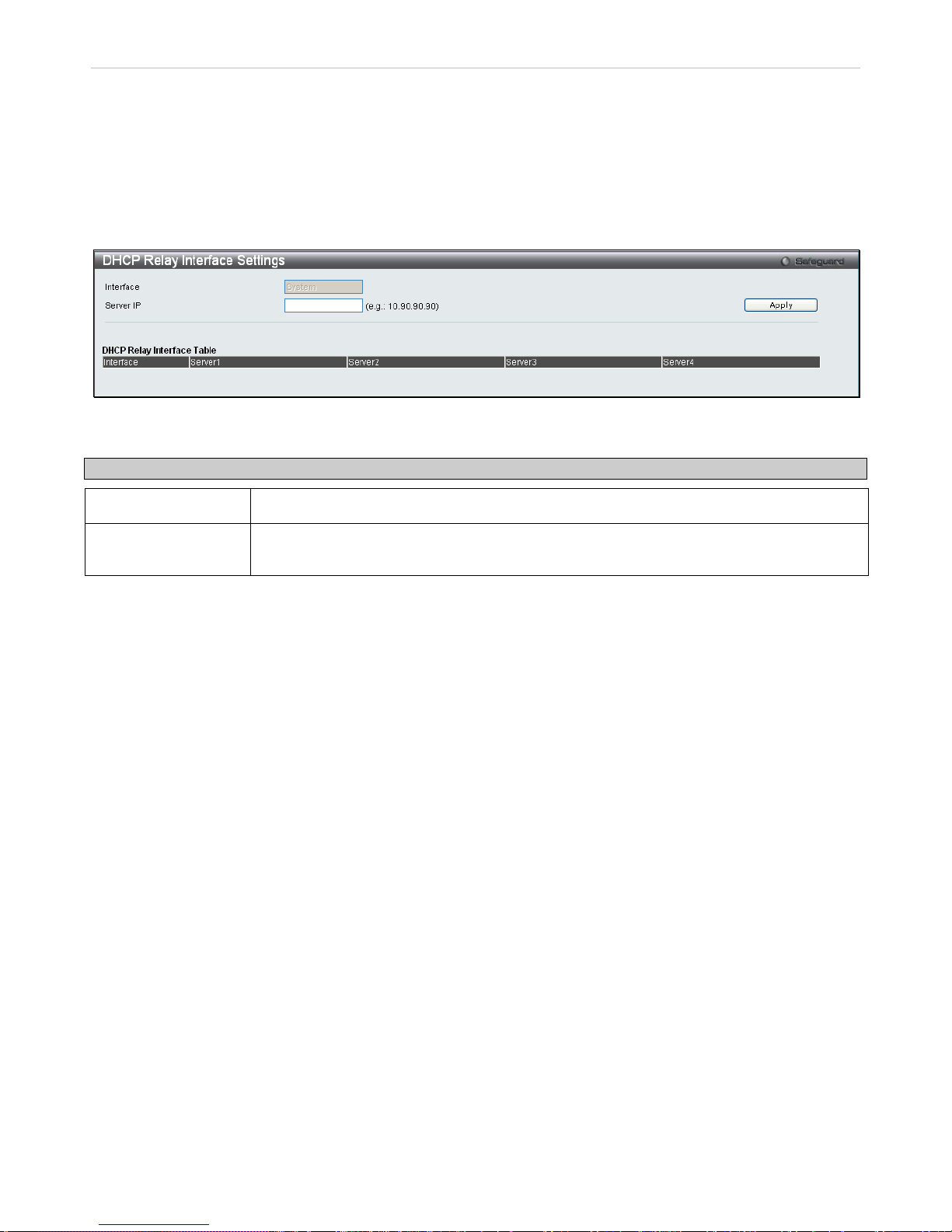
xStack® DES-3200 Series Layer 2 Ethernet Managed Switch WEB UI Reference Guide
29
DHCP Relay Interface Settings
This window allows t he user to set up a server, by IP addr ess, for r elaying DHC P/ BOOT P information to the Switc h.
The user may enter a pre viously configured IP interface on the Switch that will be connected dir ectly to the DHCP
server using the followi ng wind o w. Properly configured setti ngs will be d ispl ayed in the DHCP Re lay Interface Table at
the bottom of the following window. The user may add up to four server IP’s per IP interface on the Switch.
To enable and configur e DHCP Relay Global Sett ings on the Switch, c lick Configuration > DHCP Relay > DHCP
Relay Interface Settings:
Figure 2 - 17. DHCP Relay Interface Settings window
The following parameters may be configured or viewed.
Parameter Description
Interface
The IP interface on the Switch that will be connected directly to the Server.
Server IP
Enter the IP address of the DHC P server. Up to four server IPs can be configured per IP
Interface
DHCP Local Relay Settings
This function on the Switch allows configuration of the DHCP local relay for VLAN.
To view this window, click Configuration > DHCP Local Relay> DHCP Local Relay Settings:
Page 31
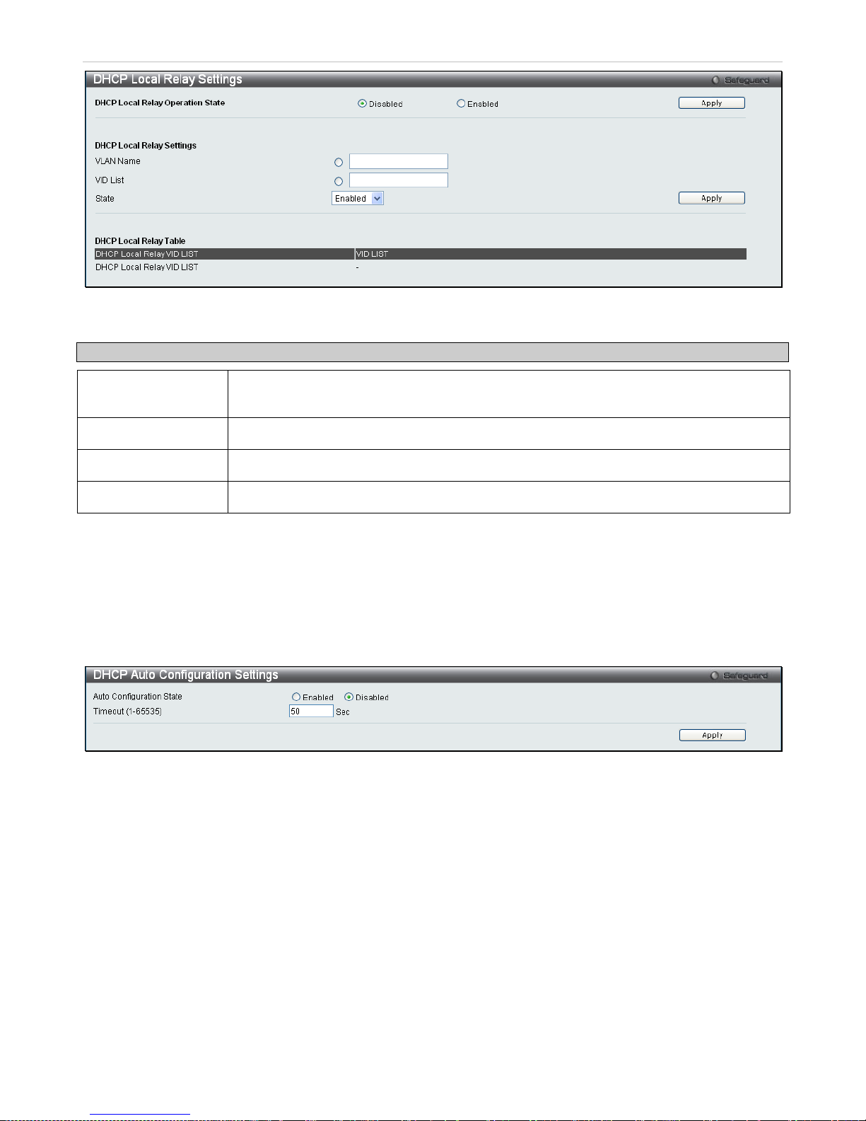
xStack® DES-3200 Series Layer 2 Ethernet Managed Switch WEB UI Reference Guide
30
Figure 2 - 18. DHCP Local Relay Settings window
The following parameters may be configured.
Parameter Description
DHCP Local Relay
Operation State
This is used to enable or disable DHCP Local Relay service on the Switch. The default is
Disabled.
VLAN Name
Enter a name of the VLAN to be enabled by DHCP local relay.
VID List
Enter a VLAN ID to be enabled by DHCP local relay.
State
This is used to enable or disable the DHCP local relay for the specified VLAN.
DHCP Auto Configuration Settings
The DHCP automatic c onfiguration function on the Switch will load a previous ly saved configuration file for current
use. When DH CP auto configuration is Enabled on t he Switch, the DHCP reply will contain a configuration file and
path name. It will then request the file from the TFTP server specified in the reply.
To view this window, click Configuration > DHCP Auto Configuration Settings:
Figure 2 - 19. DHCP Auto Configuration Settings window
When DHCP autom atic configuration is Enabled, the Sw itch becomes a DHCP client automat ically after rebooting.
The DHCP server m ust have the TFTP s erver IP address and conf iguration file nam e, and be configured to d eliver
this information in the data field of th e D HCP rep l y pac ket . The T FTP s erver m ust be run ning and have the r equest ed
configuration file in its base directory when t he request is received from the Switch. Co nsult the DHCP server and
TFTP server software instructions for information on loading a configuration file.
If the Switch is unable to complete the automatic c onfiguration process, the pr eviously saved local config uration file
present in Switch memory will be loaded.
MAC Address Aging Time
This table specifies the length of time a learned MAC Address will remain in the forwarding table without being
accessed (that is, how long a learned MAC Address is allowed to remain idle). To change this, enter a value
representing the MAC address age-out time in seconds. The MAC Address Aging Time can be set to any value
between 10 and 1,000,000 seconds. The default setting is 300 seconds.
Page 32
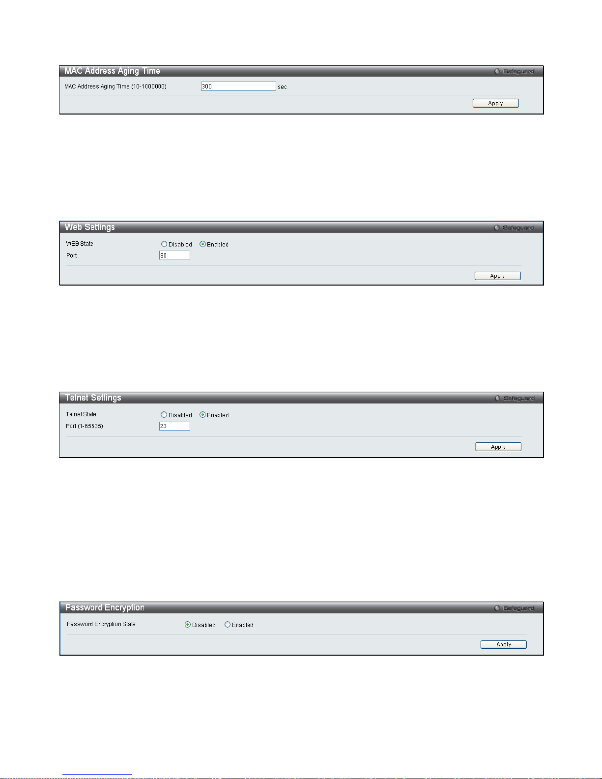
xStack® DES-3200 Series Layer 2 Ethernet Managed Switch WEB UI Reference Guide
31
To access this window, click Configuration > MAC Address Aging Time:
Figure 2 - 20. MAC Address Aging Time window
Web Settings
Web-based m anagement is Enabled by default. If you choose to disable th is by selecting Disabled, you will lose the
ability to configure the s ystem through the W eb interface as soon as these settings ar e applied. The T CP ports are
numbered between 1 and 65535. The "well-known" TCP port for the Web protocol is 80.
To access this window, click Configuration > Web Settings:
Figure 2 - 21. Web Settings window
Telnet Settings
Telnet configuration is Enabled by default. If you do not want to allow configuration of the system through Telnet
choose Disabled. The TCP ports are numbered between 1 and 65535. The "well-known" TCP port for the Telnet
protocol is 23.
To access this window, click Configuration > Telnet Settings:
Figure 2 - 22. Telnet Settings window
Password Encryption
Password Encryption c an b e En abled or D is ab led in th is windo w. It is Disabled b y default. Password encr ypti on al lows
the user to encrypt a password f or additional security. Select Enabled to change the password into encr ypted form.
When password encryption is Disabled, the password will be in plain text form. However, if the user specifies the
password in encrypted for m, or if the password has been c onverted to encr ypted form by the last enable password
encryption command, the password will still be in encrypted form and cannot be reverted back to plain text form.
To access this window, click Configuration > Password Encryption:
Figure 2 - 23. Password Encryption window
Page 33
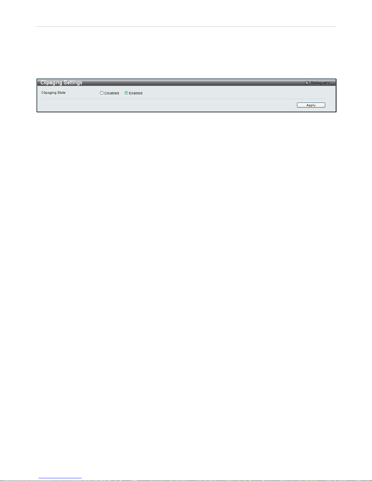
xStack® DES-3200 Series Layer 2 Ethernet Managed Switch WEB UI Reference Guide
32
CLI Paging Settings
CLI paging can be Enabled or Disabled in this window. It is Enabled by default. CLI paging settings are used when
issuing a c omm and which c auses t he conso le scree n to rap idly scro ll throu gh sever al pages. This c ommand w ill cause
the console to pause at the end of each page.
To access this window, click Configuration > CLI Paging Settings:
Figure 2 - 24. CLI Paging Settings window
Page 34
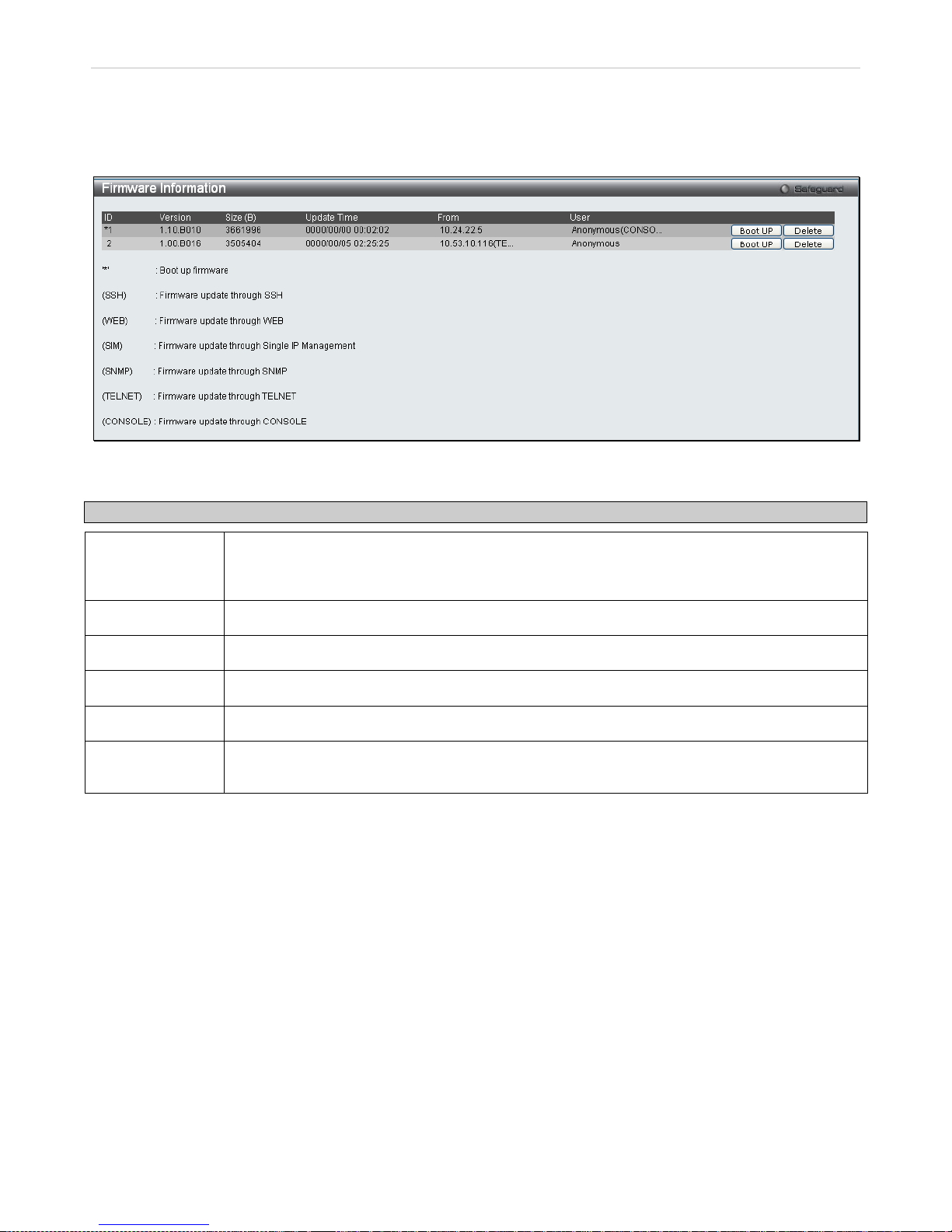
xStack® DES-3200 Series Layer 2 Ethernet Managed Switch WEB UI Reference Guide
33
Firmware Information
Information about current firmware images stored on the Switch can be viewed.
To access this window, click Configuration > Firmware Information:
Figure 2 - 25. Firmware Information window
This window holds the following information:
Parameter Description
ID
States the image ID number of the firmware in the Switch’s mem ory. The Switch can store two
firmware images for use. Im age ID 1 will be the default boot up firm ware for the Switch unless
otherwise configured by the user.
Version
States the firmware version.
Size (Bytes)
States the size of the corresponding firmware, in bytes.
Update Time
States the specific time the firmware version was downloaded to the Switch.
From
States the IP address of the origin of the firmware.
User
States the user who dow nloaded the firmware. T his field may read “Anon ymous” or “Unknown”
for users that are unidentified.
Page 35
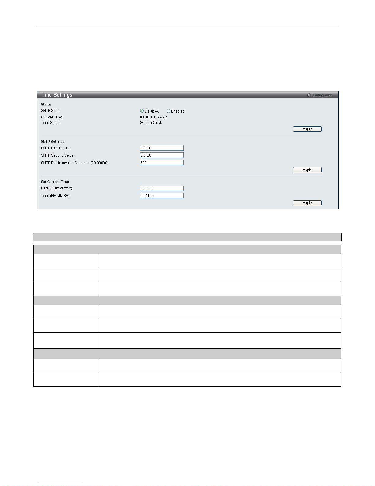
xStack® DES-3200 Series Layer 2 Ethernet Managed Switch WEB UI Reference Guide
34
SNTP Settings
The SNTP Settings folder offers two windows: Time Settings and Time Zone Settings.
Time Settings
To configure the time settings for the Switch, click Configuration > SNTP Settings > Time Settings:
Figure 2 - 26. Time Settings window
The following parameters can be set or are displayed:
Parameter Description
Status
SNTP State
Use the radio button to select an Enabled or Disabled SNTP state.
Current Time
Displays the Current Time set on the Switch.
Time Source
Displays the time source for the system.
SNTP Settings
SNTP First Server
This is the IP address of the primary server the SNTP information will be taken from.
SNTP Second Server
This is the IP address of the secondary server the SNTP information will be taken from.
SNTP Poll Interval in
Seconds (30-99999)
This is the interval, in seconds, between requests for updated SNTP information.
Set Current Time
Date (DD/MM/YYYY)
Enter the current date in day, month and year to update the system clock.
Time (HH:MM:SS)
Enter the current time in hours, minutes, and seconds.
Click Apply to implement changes made.
Page 36
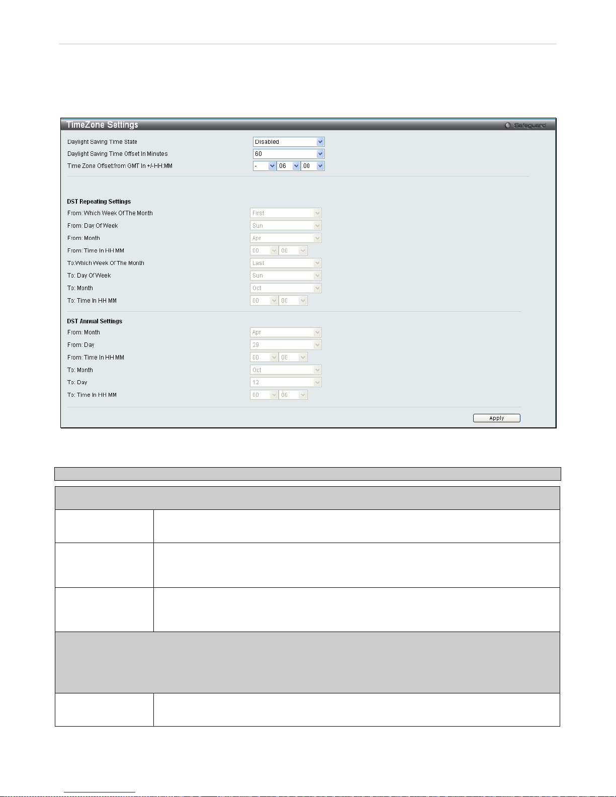
xStack® DES-3200 Series Layer 2 Ethernet Managed Switch WEB UI Reference Guide
35
Time Zone Settings
The following window is used to configure time zones and Daylight Savings Time settings for SNTP.
To configure the time zone settings for the Switch, click Configuration > SNTP Settings > Time Zone Settings:
Figure 2 - 27. Time Zone Settings window
The following parameters can be set:
Parameter Description
Time Zone and DST
Daylight Saving
Time State
Use this pull-down menu to enable or disable the DST Settings.
Daylight Saving
Time Offset in
Minutes
Use this pull-down menu to specify the amount of time that will constitute your local DST offset
30, 60, 90, or 120 minutes.
Time Zone Offset
from GMT in +/HH:MM
Use these pull-down menus to specify your local time zone's offset from Greenwich Mean
Time (GMT.)
DST Repeating Settings
Using repeating m ode will enable DST seasonal time adjustm ent. Repeating m ode requires that the DST beginning
and ending date be spec ified using a formula. For example, specif y to begin DST on Saturday during the second
week of April and end DST on Sunday during the last week of October.
From: Which Week
of the Month
Enter the week of the month that DST will start on.
Page 37

xStack® DES-3200 Series Layer 2 Ethernet Managed Switch WEB UI Reference Guide
36
From: Day of the
Week
Enter the day of the week that DST will start on.
From: Month
Enter the month DST will start on.
From: Time in
HH:MM
Enter the time of day that DST will start on.
To: Which Week of
the Month
Enter the week of the month the DST will end.
To: Day of the
Week
Enter the day of the week that DST will end.
To: Month
Enter the month that DST will end.
To:Time in HH:MM
Enter the time DST will end.
DST Annual Settings
Using annual m ode will enable DST seasonal time adjustment. Annual m ode requires that the DST beg inning and
ending date be specified concisely. For example, specify to begin DST on April 3 and end DST on October 14.
From: Month
Enter the month DST will start on, each year.
From: Day
Enter the day of the week DST will start on, each year.
From: Time in
HH:MM
Enter the time of day DST will start on, each year.
To: Month
Enter the month DST will end, each year.
To: Day
Enter the date DST will end, each year.
To: Time in HH:MM
Enter the time of day that DST will end, each year.
Click Apply to implement changes made in this window.
Page 38
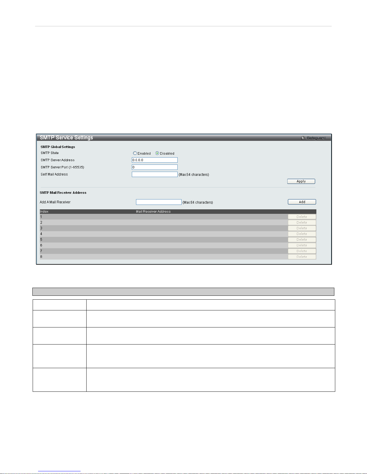
xStack® DES-3200 Series Layer 2 Ethernet Managed Switch WEB UI Reference Guide
37
SMTP Settings
SMTP or Simple Mail T r ans f er Pr otoc ol is a f unc tion of the S witc h th at w ill s e nd switch events to mail recipients based
on e-mail addresses en ter e d in the windo w b elo w. The Switch is to b e c onf igured as a client of SMT P wh ile t he s er ver
is a remote device that w ill receive messages fr om the Switch, place the appropr iate information into an e-mail and
deliver it to recipients configured on the Switch. This can benefit the Switch administrator by simplifying the
management of small work groups or wiring closets , increasing the speed of handling emergenc y Switch events, and
enhancing security by recording questionable events occurring on the Switch.
Users can set up t he SMT P ser ver f or th e Sw itch, al o ng with sett ing e-m ail addr esses to which s witch l og f iles can be
sent when a problem arises on the Switch.
SMTP Service Settings
To view the following window, click Configuration > SMTP Service Settings:
Figure 2 - 28. SMTP Service Settings window
The following parameters may be configured or viewed:
Parameter Description
SMTP State
Use the radio button to enable or disable the SMTP service on this device.
SMTP Server
Address
Enter the IP address of the SMTP server on a rem ote device. This will be the de vice that sends
out the mail for you.
SMTP Server Port
(1-65535)
Enter the virtual port number that the Switc h wi ll conn ect with on the S MT P server . The c omm on
port number for SMTP is 25, yet a value between 1 and 65535 can be chosen.
Self Mail Address
Enter the e-mail address from which mail mes sages will be sent. This address will be the “fr om”
address on the e-mail m essage sent to a rec ipie nt. Onl y one self-m ail addres s can be c onfig ured
for this Switch. This string can be no more that 64 alphanumeric characters.
Add A Mail
Receiver
Enter an e-mail address a nd click the Add button. Up to eight e-m ail addresses can be added
per Switch. To delete th ese addresses from the Switc h, click the corr esponding Delete button in
the SMTP Mail Receiver Address table at the bottom of the window.
Page 39
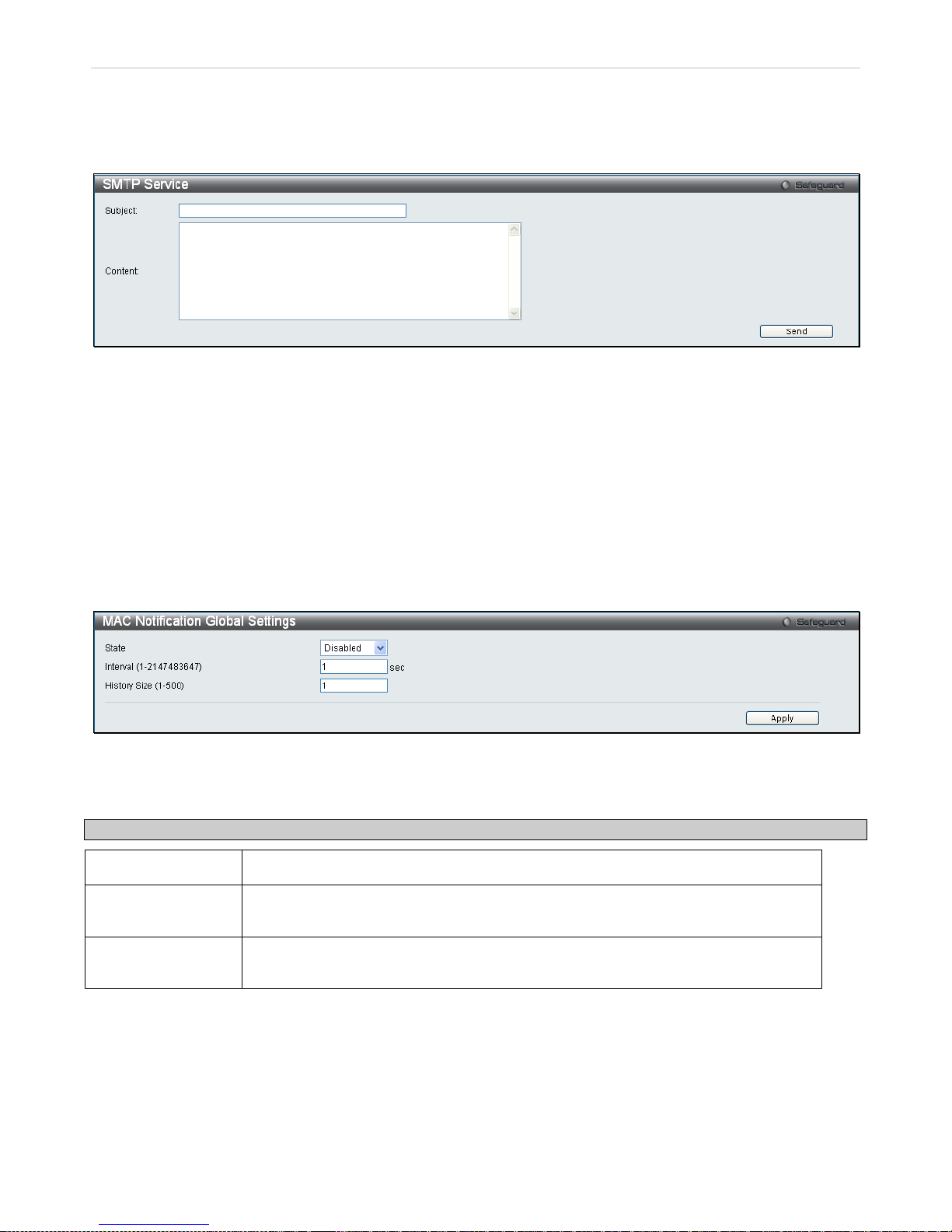
xStack® DES-3200 Series Layer 2 Ethernet Managed Switch WEB UI Reference Guide
38
SMTP Service
This window is used to test the SMTP Service Settings configured in the previous window.
To view the following window, click Configuration > SMTP Service:
Figure 2 - 29. SMTP Service window
To test to see if the SMTP settings are working properly, enter a Subject, Content, and then click the Send button.
MAC Notification Settings
MAC Notification is us ed t o monitor MAC address es le ar ned and ent er ed int o th e f or warding database. To globally set
MAC notification on the Switch, open the following window by opening the MAC Notification Settings in the
Configuration folder.
MAC Notification Global Settings
To configure the MAC N ot ific ati on Gl oba l Sett in gs f or the S witch , click Configuration > MAC Notification Settings >
MAC Notification Global Settings
Figure 2 - 30. MAC Notification Global Settings window
The following parameters may be viewed and modified:
Parameter Description
State
Enable or disable MAC notification globally on the Switch.
Interval
(1-2147483647 sec)
The time in seconds between notifications.
History Size
(1-500)
The maximum number of entr ies l ist ed in t he history log used for notif ic ati on. U p t o 500
entries can be specified.
Click Apply to implement changes.
MAC Notification Port Settings
To configure the MAC Noti fication Port Settings for the S witch, click Configuration > MAC Notification Settings >
MAC Notification Port Settings:
Page 40
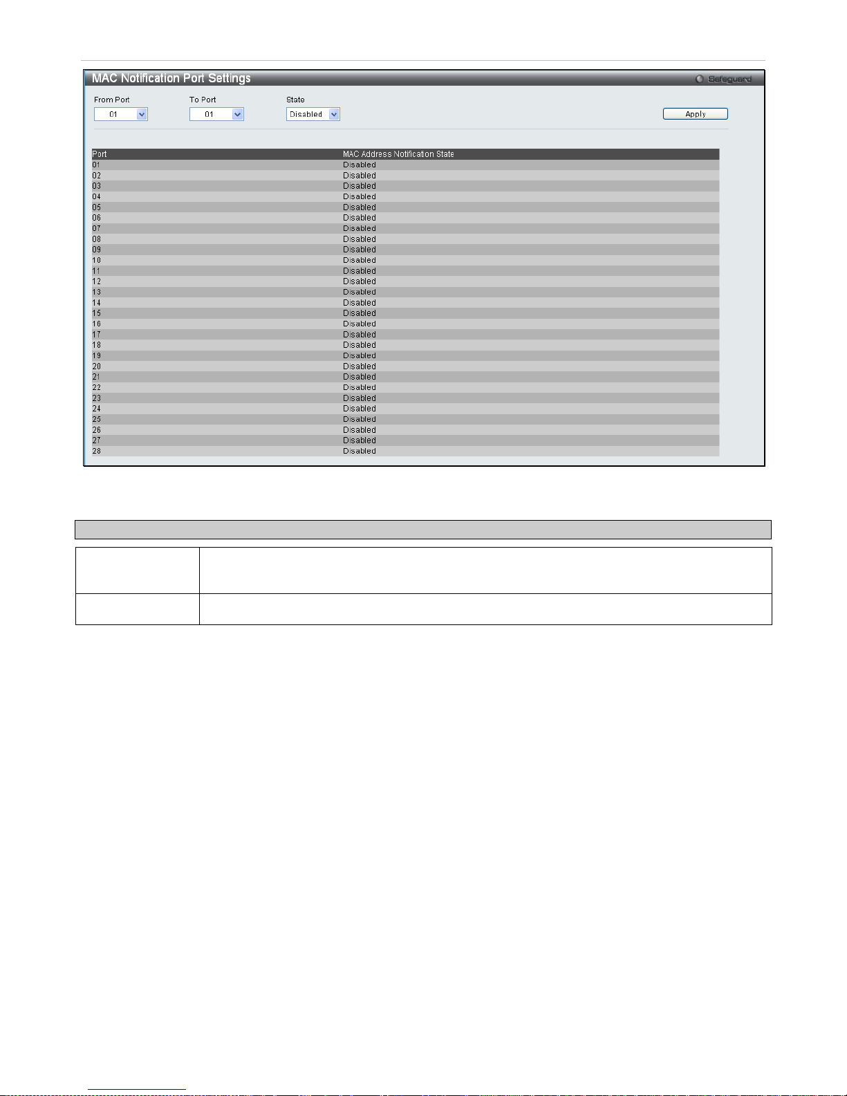
xStack® DES-3200 Series Layer 2 Ethernet Managed Switch WEB UI Reference Guide
39
Figure 2 - 31. MAC Notification Port Settings window
The following parameters may be modified:
Parameter Description
From Port/To
Port
Select a port or group of ports to enable for MAC notification using the pull-do wn menus.
State
Enable MAC Notification for the ports selected using the pull-down menu.
Click Apply to implement changes.
SNMP Settings
Simple Network Management Protocol (SNMP) is an OSI Layer 7 (Application Layer) designed specifically for
managing and monitoring network devices. SNMP enables network management stations to read and modify the
settings of gateways, routers, switches, and other network devices. Use SNMP to configure system features for proper
operation, monitor performance and detect potential problems in the Switch, switch group or network.
Managed devices that support SNMP inc lude software (r eferred to as an ag ent), which runs locally on the dev ice. A
defined set of variables (m anaged objects ) is maintained b y the SNMP agent and used to m anage the de vice. These
objects are defined in a Management Information Base (MIB), which provides a standard presentation of the
information controlled by the on-board SNMP agent. SNMP defin es both the f ormat of the MIB specificat ions and th e
protocol used to access this information over the network.
The Switch supports the SNMP versions 1, 2c, and 3. Choose which v ersion to monitor and control the S witch. The
three versions of SNMP vary in the level of security provided between the management station and the network
device.
In SNMP v.1 and v.2, user authe ntication is accomplished us ing 'community strings', which func tion like passwords.
The remote user SNMP applica tion and the S witch SNMP mus t use the same com munity string. SNM P packets fr om
any station that has not been authenticated are ignored (dropped).
The default community strings for the Switch used for SNMP v.1 and v.2 management access are:
• public - Allows authorized management stations to retrieve MIB objects.
• private - Allows authorized management stations to retrieve and modify MIB objects.
Page 41
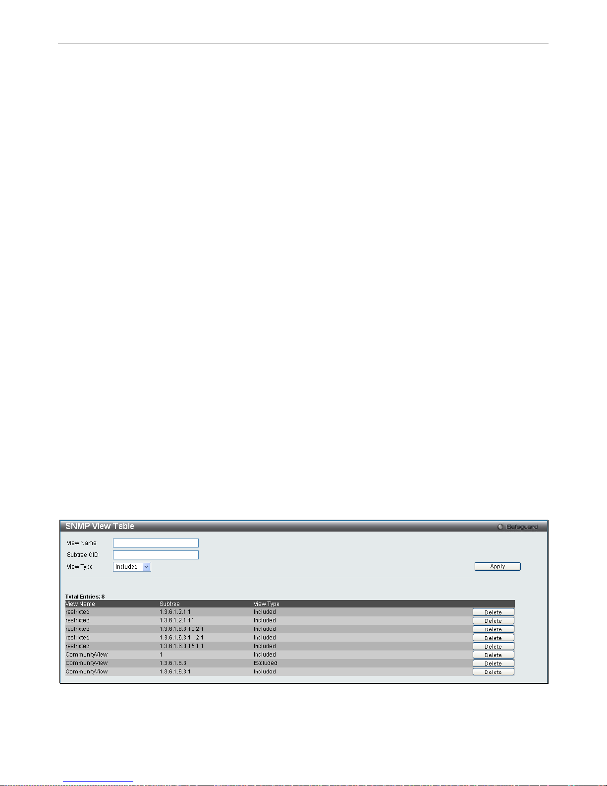
xStack® DES-3200 Series Layer 2 Ethernet Managed Switch WEB UI Reference Guide
40
SNMPv3 uses a more sophisticated authentication process that is separated into two parts. The first part is to
maintain a list of users and the ir attributes that are allowed to act as SN MP managers. The second part describes
what each user on that list can do as an SNMP manager.
The Switch allows grou ps of user s to be listed and c onf igured with a shar ed set of priv ileges . The SNM P ve rsion m a y
also be set for a l iste d grou p of S NM P manager s. T hus , you m ay creat e a group of SN MP m anag ers that ar e allo wed
to view read-only inform ation or receive traps using SNMPv1 while assigning a higher level of security to another
group, granting read/write privileges using SNMPv3.
Using SNMPv3 individual users or groups of SNMP managers can be allowed to perform or be restricted from
performing specific SNM P management functions. The functions a llowed or restricted are defined using th e Object
Identifier (OID) assoc iated with a specific MIB. An additional la yer of security is available f or SNMPv3 in that SNMP
messages ma y be encrypted. T o read more about how to conf igure SNMPv3 settings for the Switch read the next
section.
Traps
Traps are messages that al ert network pers onnel of events that occ ur on th e Swit ch. The events can be as serious as
a reboot (someone accidentally turned OFF the Switch), or less serious like a port status change. The Switch
generates traps and sends them to the trap recipient ( or network manager). T ypical traps include trap messages f or
Authentication Failure, Topology Change and Broadcast\Mult icas t Storm.
MIBs
The Switch in the Man agement Information B as e (MI B) st ores management and c ount er inf or mation. The Switch us es
the standard MIB-II Manag ement Information Base module. Con sequently, values for MIB objects can be retrieved
from any SNMP-based network m anagement s oftware. In add ition to the s tandard MIB -II, the Switch a lso supports i ts
own proprietary enter prise MIB as an extended Management Inf ormation Base. Specifying the MIB Object Ident ifier
may also retrieve the proprietary MIB. MIB values can be either read-only or read-write.
The Switch incorporates a flexible SNMP management for the switch ing environm ent. SNMP management can be
customized to suit the needs of the networks and the preferences of the network administrator.
The Switch supports the Si mple Network Management Protoco l (SNMP) vers ions 1, 2c, and 3. T he administrator c an
specify the SNMP versi on used to monitor and control t he Switch. The three versions of SN MP vary in the level of
security provided between the management station and the network device.
SNMP View Table
This window is used to ass ign views to community strings or SNMP groups th at define which MIB objects can be
accessed by a remote SNMP manager.
To configure SNMP View Settings for the Switch, click Configuration > SNMP Settings > SNMP View Table:
Figure 2 - 32. SNMP View Table window
The following parameters can be set:
Page 42
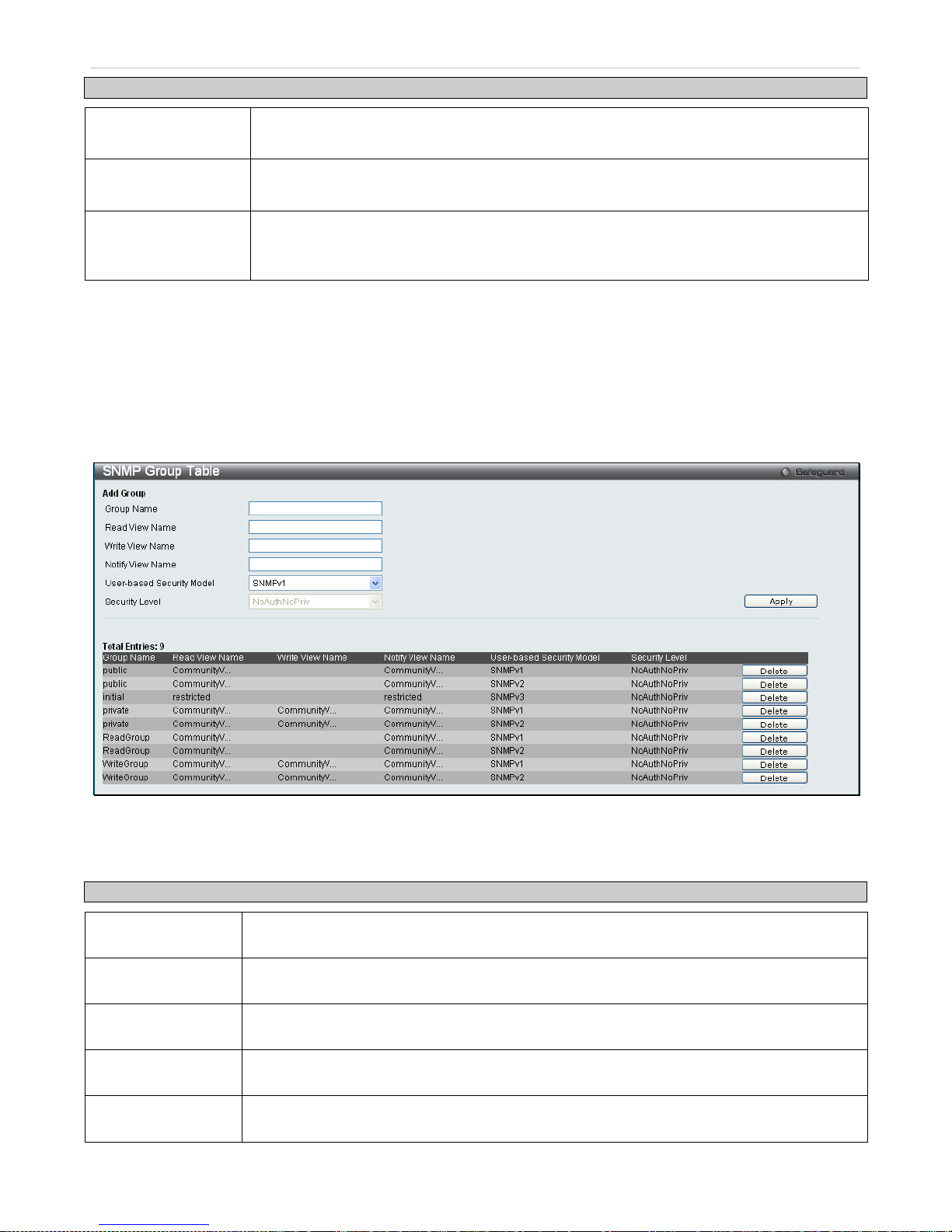
xStack® DES-3200 Series Layer 2 Ethernet Managed Switch WEB UI Reference Guide
41
Parameter Description
View Name
Type an alphanumer ic string of up to 32 charac ters. This is used t o identify the ne w SNMP
view being created.
Subtree OID
Type the Object Ide ntifier (OID) Subtree for the view. T he OID identif ies an objec t tree (MI B
tree) that will be included or excluded from access by an SNMP manager.
View Type Select Included to include this object in the list of objects that an SNMP manager can
access. Select Excluded to exclude this object from the list of objects that an SNMP
manager can access.
To implement your new settings, click Apply. To delete an entry click the corresponding Delete button.
SNMP Group Table
An SNMP Group created with th is table maps SNMP users (identif ie d in t he SNM P User T able w in do w) or c om munity
strings to the views created in the previous window.
To view this window, click Configuration > SNMP Settings > SNMP Group Table:
Figure 2 - 33. SNMP Group Table window
To delete an existing SNMP Group Table entry, click the corresponding Delete button.
The following parameters can be set:
Parameter Description
Group Name
Type an alphanumer ic string of up to 32 characters. T his is used to identify the new SNM P
group of SNMP users.
Read View Name
Specify an SNMP group name for users that are allowed SNMP read privileges to the Switch’s
SNMP agent.
Write View Name
Specify an SNMP group name for users that are allowed SNMP write privileges to the
Switch's SNMP agent.
Notify View Name
Specify an SNMP group na me for users that c an receive SNMP trap m ess ages generated b y
the Switch's SNMP agent.
User-based
Security Model
SNMPv1 - Specifies that S NMP vers i on 1 will be used .
SNMPv2 - Specifies that SNMP version 2c will be used. The SNMPv2 supports both
Page 43
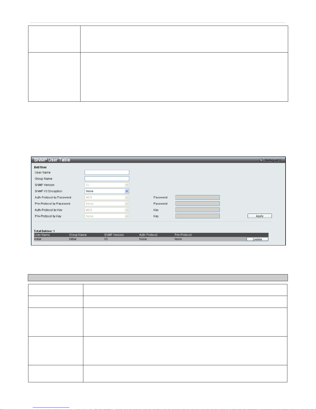
xStack® DES-3200 Series Layer 2 Ethernet Managed Switch WEB UI Reference Guide
42
centralized and distribu ted network management strategies . It includes improvements in the
Structure of Management Information (SMI) and adds some security features.
SNMPv3 - Spec ifies that the SNM P version 3 will be used. SNMPv3 pro vides sec ure access
to devices through a combination of authentication and encrypting packets over the network.
Security Level
The Security Level settings only apply to SNMPv3.
NoAuthNoPriv - Specifies that there will be no auth or izat ion a nd no enc ryption of pack ets s ent
between the Switch and a remote SNMP manager.
AuthNoPriv - Specifies that authorizati on will be required, but there will be no encryption of
packets sent between the Switch and a remote SNMP manager.
AuthPriv - Specifies that authorization will be required, and that packets sent between the
Switch and a remote S NM P m anger will be encr ypted .
To implement the new settings, click Apply.
SNMP User Table
This window displays all of the SNMP User's currently configured on the Switch and also allows you to add new users.
To view this window, click Configuration > SNMP Settings > SNMP User Table:
Figure 2 - 34. SNMP User Table window
To delete an existing SNMP User Table entry, click the corresponding Delete button.
The following parameters may be set:
Parameter Description
User Name
An alphanumeric string of up to 32 characters. This is used to identify the SNMP users.
Group Name
This name is used to specify the SNMP group created can request SNMP messages.
SNMP Version V1 - Indicates that SNMP version 1 is in use.
V2 - Indicates that SNMP version 2 is in use.
V3 - Indicates that SNMP version 3 is in use.
SNMP V3 Encryption None – Indicates that there is no SNMP V3 Encryption
Password – Indicates that t here is SNM P V3 Encryption through a password
Key – Indicates that there is SNMP V3 Encryption through a key.
Auth-Protocol by
Password
MD5 - Indicates that the HMAC-MD5-96 authentication level will be used.
Page 44
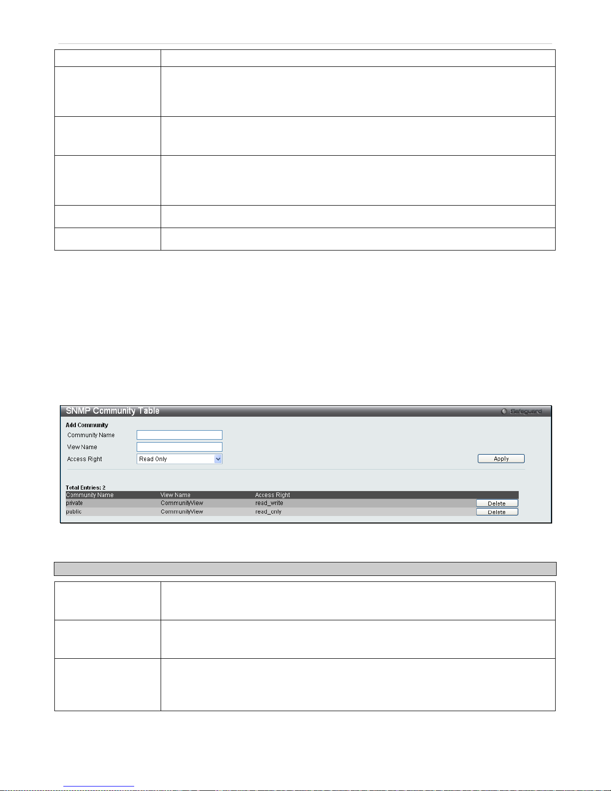
xStack® DES-3200 Series Layer 2 Ethernet Managed Switch WEB UI Reference Guide
43
SHA - Indicates that the HMAC-SHA authentication protocol will be used.
Priv-Protocol by
Password
None - Indicates that no authorization protocol is in use.
DES - Indicates that DES 56-bit encryption is in use based on the CBC-DES (DES-56)
standard.
Auth-Protocol by Key MD5 - Indicates that the HMAC-MD5-96 authentication level will be used.
SHA - Indicates that the HMAC-SHA authentication protocol will be used.
Priv-Protocol by Key None - Indicates that no authorization protocol is in use.
DES - Indicates that DES 56-bit encryption is in use based on the CBC-DES (DES-56)
standard.
Password
Enter a Password when SNMP V3 Encryption is enabled for Password mode.
Key
Enter a Key when SNMP V3 Encryption is enabled for Key mode.
To implement changes made, click Apply.
SNMP Community Table
Use this table to view exis ting SNMP Comm unity Table configurations and to create a SNMP com munity string to
define the relationship between the SNMP manager and an agent. The community string acts like a password to
permit access to the ag ent on the Switch. One or more of the fol lowing characteristics can be associated with the
community string:
Any MIB view that defines the subset of all MIB objects will be accessible to the SNMP community.
Read/write or read-only level permission for the MIB objects accessible to the SNMP community.
To configure SNMP Community entries, click Configuration > SNMP Settings > SNMP Community Table:
Figure 2 - 35. SNMP Community Table window
The following parameters can set:
Parameter Description
Community Name
Type an alphanumeric s tring of up to 32 characters that is used to identify members of an
SNMP community. This string is used like a password to give remote SNMP managers
access to MIB objects in the Switch's SNMP agent.
View Name
Type an alphanumeric s tring of up to 32 characters that is used to iden tify the group of MIB
objects that a remote SNM P manager is allowed to acc ess on the Switch. The view name
must exist in the SNMP View Table.
Access Right Read Only - Specifies that SNM P community members using the community string created
can only read the contents of the MIBs on the Switch.
Read Write - Specif ies that SNMP com munity mem bers using the comm unity string created
can read from, and write to the contents of the MIBs on the Switch.
To implement the new settings, click Apply. To delete an entry from the SNMP Community Table, click the
corresponding Delete button.
Page 45
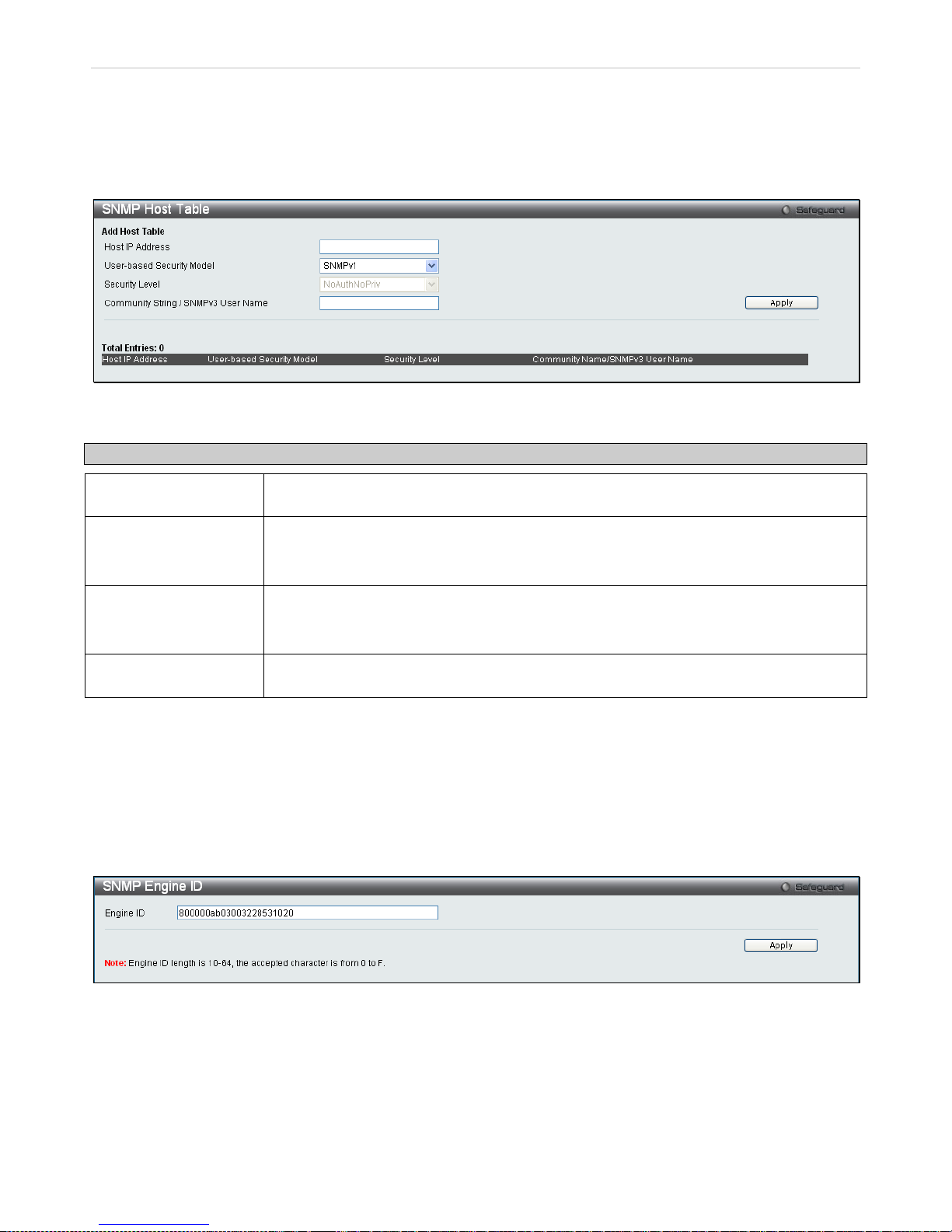
xStack® DES-3200 Series Layer 2 Ethernet Managed Switch WEB UI Reference Guide
44
SNMP Host Table
Use the SNMP Host Table window to set up SNMP trap recipients. To configur e SNMP Host Table entries, click
Configuration > SNMP Settings > SNMP Host Table
Figure 2 - 36. SNMP Host Table window
The following parameters can set:
Parameter Description
Host IP Address
Type the IP address of the r emote management station that will serve as the SNMP host
for the Switch.
User-based Security
Model
SNMPv1 - Specifies that S NMP vers i on 1 will be used .
SNMPV2c - Specifies that SNMP version 2 will be used.
SNMPV3 - To specify that the SNMP version 3 will be used.
Security Level NoAuthNoPriv – To specify a NoAuthNoPriv security level.
AuthNoPriv - To specify an AuthNoPriv security level.
AuthPriv - To specify an AuthPriv security level.
Community String/
SNMPv3 User Name
Type in the community string or SNMPv3 user name as appropriate.
To implement your new settings, click Apply.
SNMP Engine ID
The Engine ID is a unique identifier used for SNMP V3 implementations. This is an alphanumeric string used to
identify the SNMP engine on the Switch.
To display the Switch's SNMP Engine ID, click Configuration > SNMP Settings > SNMP Engine ID:
Figure 2 - 37. SNMP Engine ID window
To change the Engine ID, enter the new Engine ID in the space provided and click the Apply button.
Page 46
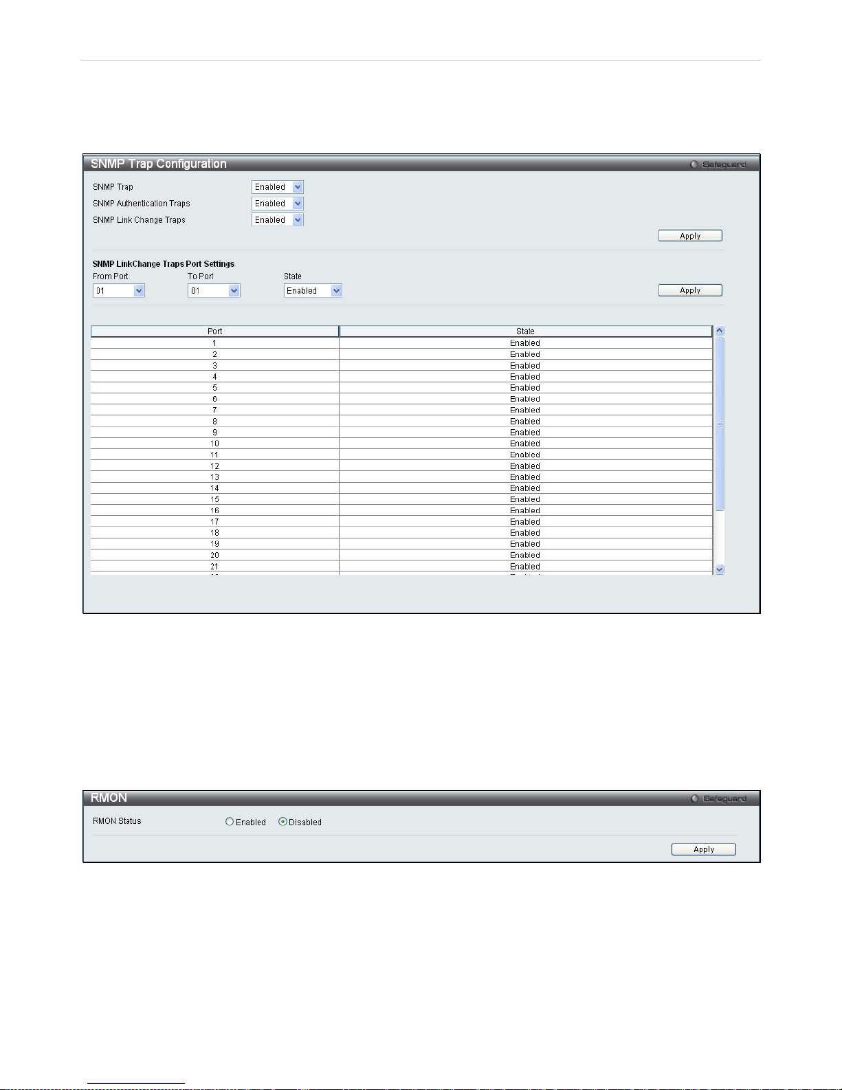
xStack® DES-3200 Series Layer 2 Ethernet Managed Switch WEB UI Reference Guide
45
SNMP Trap Configuration
The following window is used to enable and disable trap settings for the SNMP function on the Switch.
To view this window for configuration, click Configuration > SNMP Settings > SNMP Trap Configuration:
Figure 2 - 38. SNMP Trap Configuration window
To enable or disable the SNMP Trap State, SNMP Authe ntication Traps, SNMP Li nk Change Traps, and c onfigure
SNMP Link Change Tr ap Port Settings, use th e correspondin g pull-do wn menus. Click Apply to let the chan ges take
effect.
RMON
Users can enable and disable remote monitoring (RMON) status for the SNMP function on the Switch.
To view this window for configuration, click Configuration > SNMP Settings > RMON:
Figure 2 - 39. RMON window
To enable or disable RMON for SNMP, use the radio button. Click Apply when finished.
Page 47
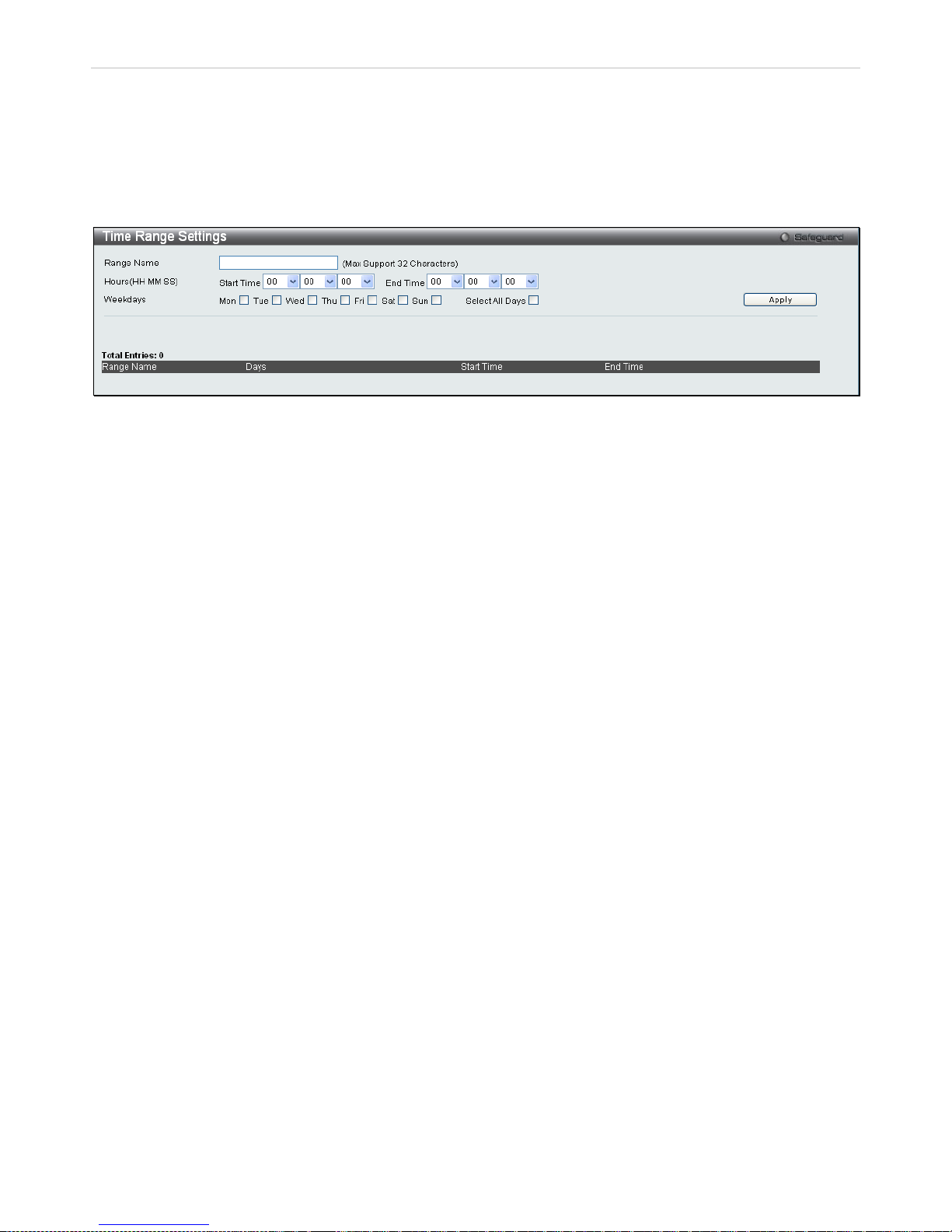
xStack® DES-3200 Series Layer 2 Ethernet Managed Switch WEB UI Reference Guide
46
Time Range Settings
This window is used in conjunc tion with the Access Prof ile feature to determine a s tarting point and an ending point,
based on days of th e week, when an Access Profile c onfiguration will be enabled on t he Switch. Once configured
here, the time range sett ings are to be applied to an access prof ile rule using th e Access Prof ile ta ble. The user m ay
enter up to 64 time range entries on the Switch.
To open this window, click Configuration > Time Range Settings:
Figure 2 - 40. Time Range Settings window
Single IP Management
Simply put, D-Link Single I P Manag em ent is a conc ept that will s tack switches to geth er over Eth ernet inste ad of using
stacking ports or modules. There are some advantages in implementing the "Single IP Management" feature:
1. SIM can simplify management of small workgroups or wiring closets while scaling the network to handle
increased bandwidth demand.
2. SIM can reduce the number of IP address needed in your network.
3. SIM can eliminate any specialized cables for stacking connectivity and remove the distance barriers that
typically limit your topology options wh en usin g other st acking technology.
Switches using D-Link Single IP Management (labeled here as SIM) must conform to the following rules:
SIM is an optional feature on the Switch and can e asily be enabled or dis abled through the C ommand Line Interf ace
or Web Interface. SIM grouping has no effect on the normal operation of the Switch in the user's network.
There are three classifications for SIM. The Commander Switch (CS), which is the master switch of the group,
Member Switch (MS), which is a switch that is recognized by the CS a m ember of a SIM group, and a Candidate
Switch (CaS), which is a Switch that has a ph ysical lin k to the SIM gr oup but has not been rec ognized b y the CS as a
member of the SIM group.
A SIM group can only have one Commander Switch (CS).
All switches in a part icular SIM group m ust be in the same IP subnet (broadcast domain). M embers of a SI M group
cannot cross a router.
A SIM group accepts up to 33 switches (numbered 0-32); including the Commander Switch (numbered 0).
There is no limit to the num ber of SIM grou ps in the s am e IP s ubnet (bro adcast d om ain) ; however a single switc h can
only belong to one group.
If multiple VLANs are configured, the SIM group will only utilize the system VLAN on any switch.
SIM allows intermediat e devices that do not support SIM. T his enables the user to manage s witches that are more
than one hop away from the CS.
The SIM group is a group of swit ches that are m anaged as a single entit y. SIM switches m ay take on thr ee different
roles:
1. Commander Switch (CS) - This is a s witch t hat has b een m anuall y conf igured a s the c ontrol ling device for a
group, and takes on the following characteristics:
It has an IP Address.
It is not a commander switch or member switch of another Single IP group.
It is connected to the member switches through its management VLAN.
2. Member Switch (M S) - This is a switch th at has j oin ed a s ingl e IP gro up an d is ac ces s ible fr om the CS, an d it
takes on the following characteristics:
It is not a CS or MS of another Single IP group.
Page 48

xStack® DES-3200 Series Layer 2 Ethernet Managed Switch WEB UI Reference Guide
47
It is connected to the CS through the CS management VLAN.
3. Candidate Switch (CaS) - T his is a switch that is ready to join a S IM group but is not yet a m ember of the
SIM group. The Candidat e Switch m a y join the SIM group of a switc h b y manuall y conf iguring it to be a MS of
a SIM group. A switch c onfigured as a CaS is not a m ember of a SIM group and will tak e on the following
characteristics:
It is not a CS or MS of another Single IP group.
It is connected to the CS through the CS management VLAN
After configuring one switc h to operate as the CS of a SIM group, additi onal switches may join the group throug h a
direct connection to the Commander switch. Only the Commander switch will allow entry to the candidate switch
enabled for SIM. The CS will then serve as the in band entr y point for access to the MS. The CS's IP address will
become the path to all MS 's of the group and the CS's Administrator's password, and/or authentication will contr ol
access to all MS's of the SIM group.
With SIM enabled, the applications in the CS will redirect the packet instead of executing the packets. The
applications will decode the packet from the administrator, modify some data, and then send it to the MS. After
execution, the CS may receive a response packet from the MS, which it will encode and send it back to the
administrator.
When a CaS becomes a MS, it autom atically becomes a member of the f irst SNMP community (includes read/write
and read only) to which the CS belongs. However, if a MS has its own IP address, it can belong to SNMP
communities to which other switches in the group, including the CS, do not belong.
The Upgrade to v1.6
To better improve SIM management, the Switch has been upgraded to version 1.6 in this release. Many
improvements have been made, including:
1. The Commander Switc h (CS) now has the capabilit y to automatically rediscover m ember switches that have left
the SIM group, either throu gh a reboot or web malfunc tion. This feature is acc omplished through the us e of Discover
packets and Maintain pack ets that previousl y set SIM members will em it after a reboot. Once a MS has had its MAC
address and password sa ved to the CS’s dat abase, if a rebo ot occ urs in t he MS, the CS will k eep this MS inf orm ation
in its database and when a MS has been rediscovered, it will add th e MS back into the SIM tree autom atically. No
configuration will be necessary to rediscover these switches.
There are some inst ances where pre-saved MS switches cannot be red iscovered. For exam ple, if the Switch is stil l
powered down, if it has become the member of another group, or if it has been configured to be a Commander Switch,
the rediscovery process cannot occur.
2. The topology map now inc ludes new features for connecti ons that are a member of a port tr unking group. It will
display the speed and number of Ethernet connections creating this port trunk group.
3. This version will suppo rt multiple switch upload and downloads for firmware, conf iguration files and log files, as
follows:
• Firmware – The switch now supports multiple MS firmware downloads from a TFTP server.
• Configuration Files – This switch now supports multiple downloading and uploading of configuration files
both to (for configuration restoration) and from (for configuration backup) MS’s, using a TFTP server..
• Log – The switch now supports uploading multiple MS log files to a TFTP server.
4. The user may zoom in and zoom out when utilizing the top ology window to get a better, m ore defined view of the
configurations.
Page 49
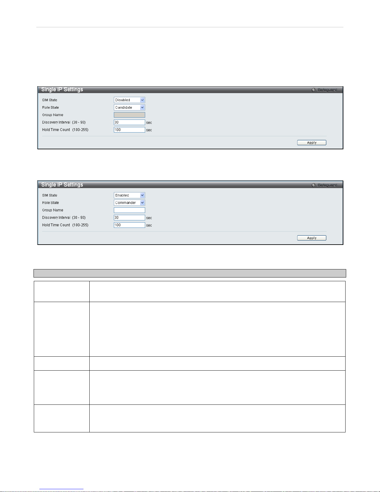
xStack® DES-3200 Series Layer 2 Ethernet Managed Switch WEB UI Reference Guide
48
Single IP Settings
All switches are set as Candid ate ( CaS) s witch es as their f actor y default conf iguratio n and Sin gle I P Manag em ent will
be disabled.
To enable SIM for th e Switch using the W eb interface, click Configuration > Single IP Management > Single IP
Settings which will reveal the following window:
Figure 2 - 41. Single IP Settings window (disabled)
Use the drop-down m enus to change the SIM State to Enabled, t he Role State to Commander, and then f ill in the
Group Name field. Click Apply to let the changes take effect.
Figure 2 - 42. Single IP Settings window (enabled)
The following parameters can be set:
Parameters Description
SIM State Use the pul l-down menu to either en able or disable the SIM s tate on the Switch. Disabled will
render all SIM functions on the Switch inoperable.
Role State
Use the pull-down menu to change the SIM role of the Switch. The two choices are:
Candidate - A Candidate Switch ( CaS) is not the m ember of a SIM group but is connected to a
Commander Switch. This is the default setting for the SIM role.
Commander - Choosing this parameter will make the Switch a Commander Sw itch (CS). The
user may join other switche s to this Switc h, over Ether net, to be part of its SIM gr oup. Choosing
this option will also enable the Switch to be configured for SIM.
Group Name
The user may enter a name for the group.
Discovery
Interval (30-90)
The user may set the discovery protocol interval, in seconds that the Switch will send out
discovery packets. Returning inf ormation to a Comm ander Switch will include inform ation about
other switches connected to it. (Ex. M S, CaS). The us er ma y set the Discover y Interval from 30
to 90 seconds.
Hold Time Count
(100-255)
This parameter ma y be set for the tim e, in seconds the Switch will hold informatio n sent to it
from other switches , utilizi ng the D iscovery Inter val. The us er ma y set the h old ti me f r om 100 to
255 seconds.
Click Apply to implement the settings.
Page 50
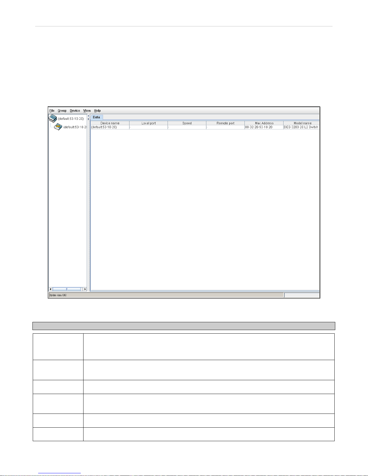
xStack® DES-3200 Series Layer 2 Ethernet Managed Switch WEB UI Reference Guide
49
After enabling the Switc h to be a Commander S witch (CS), the Single I P Management folder will then contain four
added links to aid the user in configuring SIM through the Web, including Topology, Firmware Upgrade and
Configuration File Backup/Restore and Upload Log File.
Topology
The Topology window will be us ed to c o nf igur e a nd manage the Switch w ith in t he SIM group an d r equ ires J a va sc ript
to function properly on your computer.
The Java Runtime Environment on your server should initiate and lead you to the Topology window:
Figure 2 - 43. Topology window
The Topology window holds the following information under the Data tab:
Parameter Description
Device Name
This field wi ll d isplay the Device Nam e of the s witc hes in the SIM grou p conf igur ed b y the user . If
no Device Name is configur ed by the nam e, it w ill be gi ven the nam e defau lt and tag ged with t he
last six digits of the MAC Address to identify it.
Remote Port
Displays the number of the physical port on the MS or CaS that the CS is c onnected to. The CS
will have no entry in this field.
Speed
Displays the connection speed between the CS and the MS or CaS.
Local Port
Displays the number of the physical port on the CS t hat the MS or CaS is con nected to. The CS
will have no entry in this field.
MAC Address
Displays the MAC address of the corresponding Switch.
Model Name
Displays the full model name of the corresponding Switch.
Page 51

xStack® DES-3200 Series Layer 2 Ethernet Managed Switch WEB UI Reference Guide
50
To view the Topolog y Map, click the View menu in the toolbar and then Topology, which will produce the following
window. The Topology View will refresh itself periodically (20 seconds by default).
Figure 2 - 44. Topology view
This win dow will displa y how the devices within the Singl e IP Managem ent Group are conn ected to other gr oups and
devices. Possible icons in this window are as follows:
Icon Description
Group
Layer 2 commander switch
Layer 3 commander switch
Commander switch of other group
Layer 2 member switch.
Layer 3 member switch
Member switch of other group
Layer 2 candidate switch
Layer 3 candidate switch
Unknown device
Non-SIM devices
Page 52
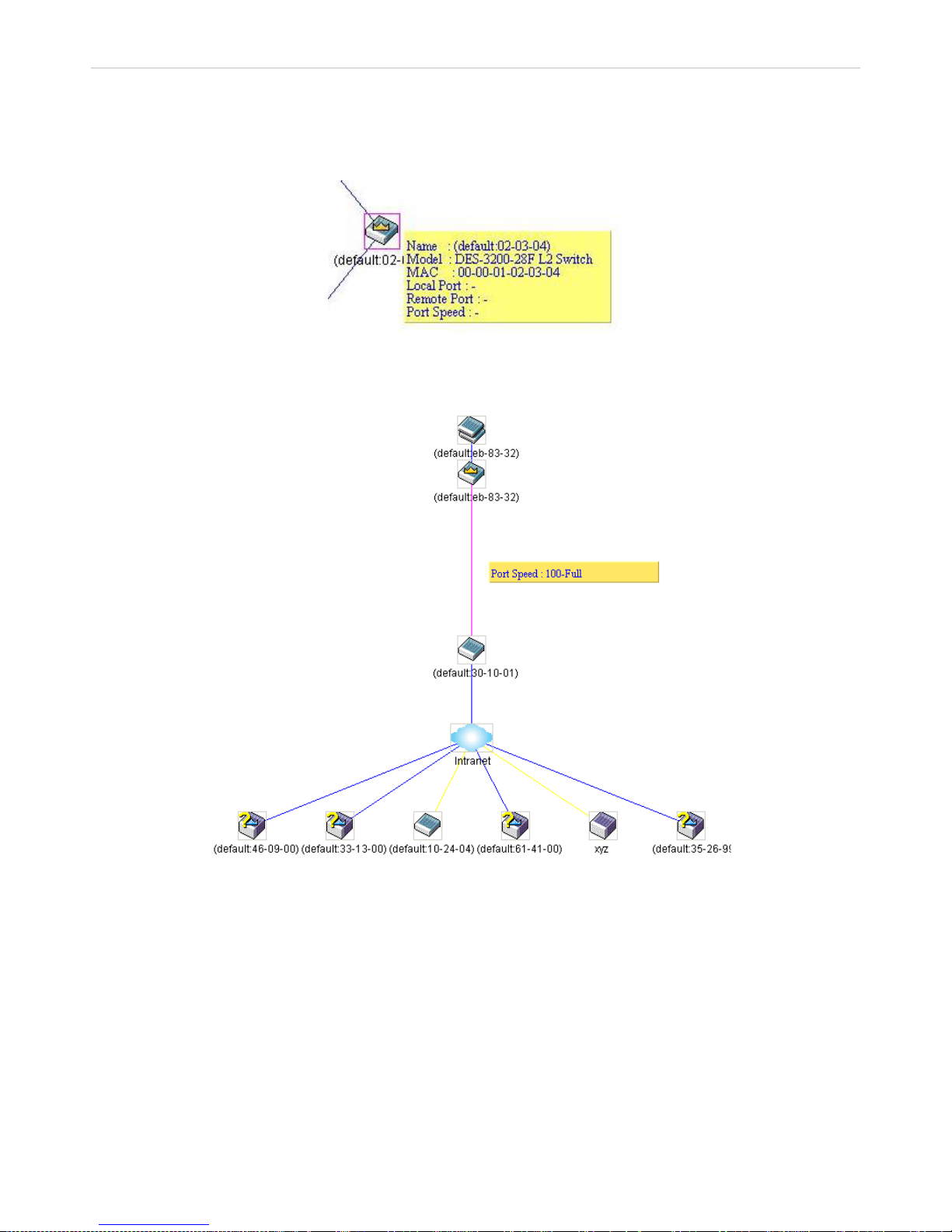
xStack® DES-3200 Series Layer 2 Ethernet Managed Switch WEB UI Reference Guide
51
Tool Tips
In the Topology view wind ow, the mouse plays an impor tant role in configuration and in vie wing device information.
Setting the mouse c ursor over a specific device in t he topology window (tool tip) w ill display the same information
about a specific device as the Tree view does. See the window below for an example:
Figure 2 - 45. Device Information Utilizing the Tool Tip
Setting the mouse c ursor over a line betw een t wo devi ces wil l displa y the co nnect ion sp eed bet wee n the t wo devic es,
as shown below:
Figure 2 - 46. Port Speed Utilizing the Tool Tip
Page 53
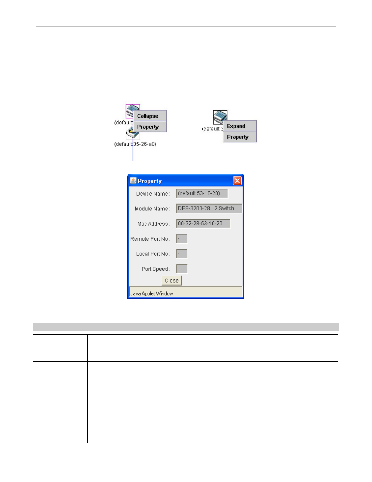
xStack® DES-3200 Series Layer 2 Ethernet Managed Switch WEB UI Reference Guide
52
Right-Click
Right-clicking on a device wil l allow the us er to perform various funct ions, depending on the role of the Switch i n the
SIM group and the icon associated with it.
Group Icon
Figure 2 - 47. Right-Clicking a Group Icon
Figure 2 - 48. Property window
This window holds the following information:
Parameter Description
Device Name
This field will display the D evice Name of the switches in the SIM group config ured by the user.
If no Device Name is c onfigured b y the nam e, it will be g iven the nam e default a nd tagged wit h
the last six digits of the MAC Address to identify it.
Module Name
Displays the full module name of the switch that was right-clicked.
MAC Address
Displays the MAC Address of the corresponding Switch.
Local Port No.
Displays the number of the ph ysical port on t he CS that th e MS or Ca S is c onne cted to. The CS
will have no entry in this field.
Remote Port No.
Displays the number of the ph ysical port on t he MS or CaS that th e C S is co nnec ted to. T he C S
will have no entry in this field.
Port Speed
Displays the connection speed between the CS and the MS or CaS
Page 54
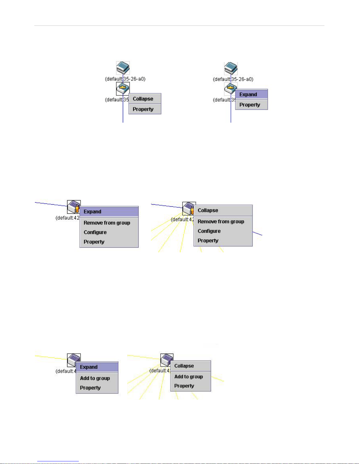
xStack® DES-3200 Series Layer 2 Ethernet Managed Switch WEB UI Reference Guide
53
Click Close to close the Property window.
Commander Switch Icon
Figure 2 - 49. Right-Clicking a Commander Icon
The following options may appear for the user to configure:
Collapse - To collapse the group that will be represented by a single icon.
Expand - To expand the SIM group, in detail.
Property - To pop up a window to display the group information.
Member Switch Icon
Figure 2 - 50. Right-Clicking a Member icon
The following options may appear for the user to configure:
Collapse - To collapse the group that will be represented by a single icon.
Expand - To expand the SIM group, in detail.
Remove from group - Remove a member from a group.
Configure - Launch the web management to configure the Switch.
Property - To pop up a windo w to displa y the device in f ormation.
Candidate Switch Icon
Figure 2 - 51. Right-Clicking a Candidate icon
The following options may appear for the user to configure:
Collapse - To collapse the group that will be represented by a single icon.
Page 55
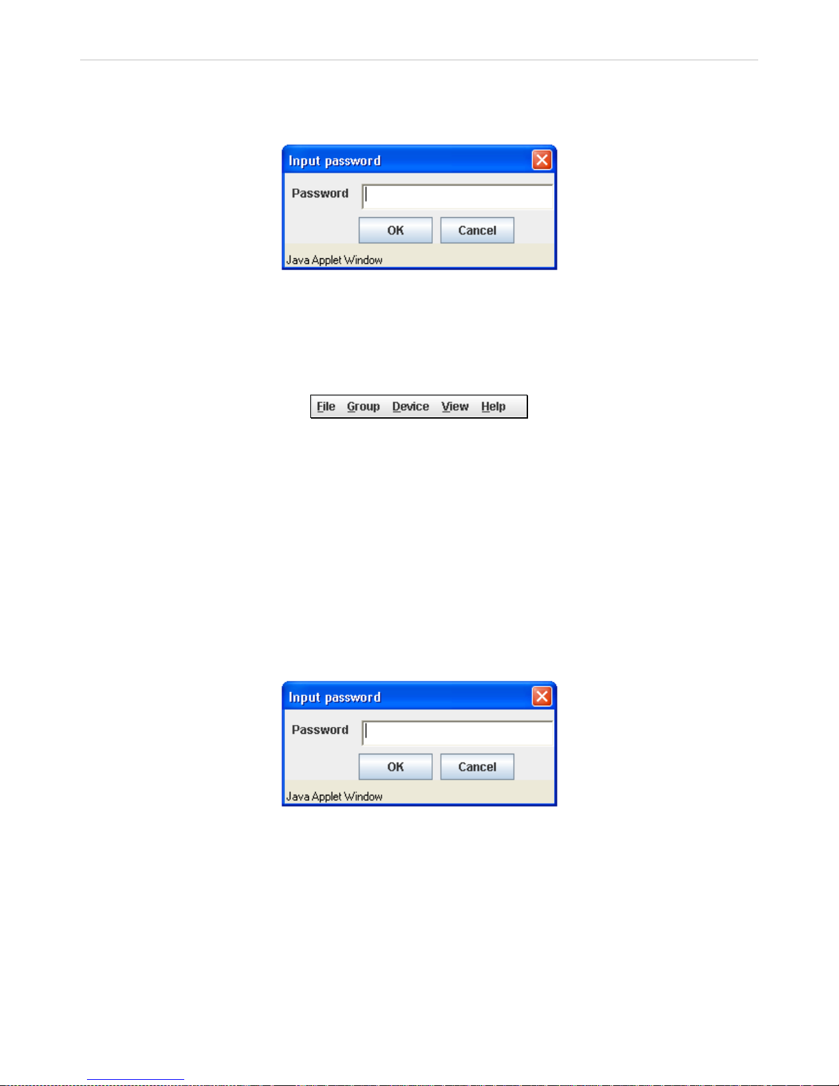
xStack® DES-3200 Series Layer 2 Ethernet Managed Switch WEB UI Reference Guide
54
Expand - To expand the SIM group in detail.
Add to group - Add a candidate to a grou p. Cl icking this option will re veal th e follow ing dialo g for t he user
to enter a password for authentication from the Candid ate Switch before being added to the SIM group.
Click OK to enter the password or Cancel to exit the window.
Figure 2 - 52. Input password window
Property - To pop up a window to dis play the device information.
Menu Bar
The Single IP Management window contains a menu bar for device configurations, as seen below.
Figure 2 - 53. Menu Bar of the Topology View
The five menus on the menu bar are as follows.
File
Print Setup - Will set the default printer properties.
Print Topology - Will print the topology map.
Preference - Will set display properties, such as polling interval, and the views to open at SIM startup.
Group
Add to group - Add a candidate to a group. Clicking this option will re veal the f ollowin g dialo g for the user
to enter a pass word for authentication from the C andidate Switch before being added to the SIM group.
Click OK to enter the password or Cancel to exit the window.
Figure 2 - 54. Input password window
Remove from Group - Remove an MS from the group.
Device
Configure - Will open the web manager for the specific device.
View
Refresh - Update the views with the latest status.
Topology - Display the Topology view.
Page 56
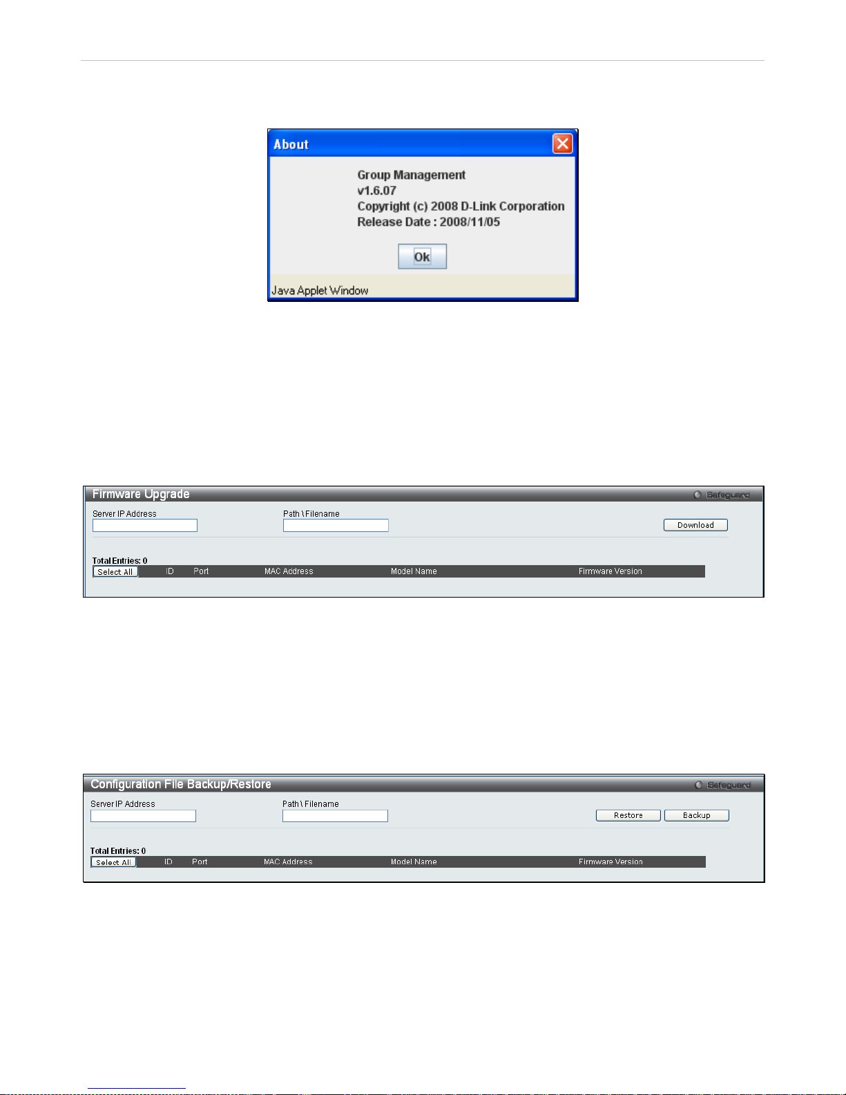
xStack® DES-3200 Series Layer 2 Ethernet Managed Switch WEB UI Reference Guide
55
Help
About - Will display the SIM information, including the current SIM version.
Figure 2 - 55. About window
Firmware Upgrade
This window is used to upgr ade firmware from the C ommander Switch to the Mem ber Switch. Member S witches will
be listed in the table and w i ll be s pec ified b y ID an d Port (port on the CS w here t h e MS r es ides ) , M AC A ddre s s, Model
Name and Firmware Version. To spec ify a certain Switch for firmware downl oad, click its corresponding check box
under the Port heading. To update the firm ware, enter the Server IP Address where the firmware res ides and enter
the Path/Filename of the firmware. Click Download to initiate the file transfer.
To access the following window, click Configuration > Single IP Management > Firmware Upgrade:
Figure 2 - 56. Firmware Upgrade window
Configuration File Backup/Restore
This window is used to u pgrade conf iguration files fro m the Comm ander Switch to the Mem ber Switch usin g a TFTP
server. Member Switches will be listed in the tab le and will be specified by ID, Port ( port on the CS where th e MS
resides), MAC Address, Model Name and F irmware Version. To update the configuration file, enter the Server IP
Address where the f ile resides and enter the Path/Filename of the configuration file. Click Restore to initiate the f ile
transfer from a TFTP s erver to the Switch. C lick Backup to backup the conf iguration file to a T FTP ser ver. To acc ess
the following window, click Configuration > Single IP Management > Configuration File Backup/Restore:
Figure 2 - 57. Configuration File Backup/Restore window
Page 57
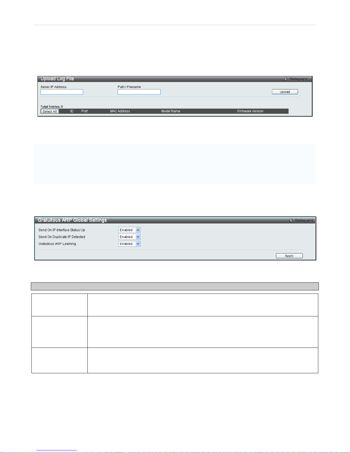
xStack® DES-3200 Series Layer 2 Ethernet Managed Switch WEB UI Reference Guide
56
Upload Log File
The following window is used to upload lo g files from SIM m ember switches to a spec ified PC. To upload a log file,
enter the Server IP addres s of the SIM m ember s witch and then enter a Path\Filename on your PC where you wish to
save this file. Click Upload to initiate the file transfer. To view this window click Configuration > Single IP
Management > Upload Log File
Figure 2 - 58. Upload Log File window
Gratuitous ARP
An ARP announcem ent ( als o known as Gratuitous ARP) is a packet (us ually an ARP Request) co nta ini ng a v alid S H A
and SPA for the host which s ent it, with TPA equal to SPA. Such a r eq uest is no t inte nde d to s o licit a r eply, but merely
updates the ARP caches of other hosts which receive the packet.
This is commonly done b y many operating s ystems on startup, a nd helps to resol ve problems which would other wise
occur if, for exam ple, a network card had rec ently been c hanged (chan ging the I P address to MAC addr ess mappin g)
and other hosts still had the old mapping in their ARP cache.
Gratuitous ARP Global Settings
To view this window, click Configuration > Gratuitous ARP > Gratuitous ARP Global Settings:
Figure 2 - 59. Gratuitous ARP Global Settings window
The following fields can be configured:
Parameter Description
Send On IP
Interface Status Up
This is used to enable or disable the sending of gr atuitous ARP request packets while an IP
interface comes up. This is us ed to aut om aticall y anno unce th e interf ace’s IP ad dres s to oth er
nodes. By default, the state is Enabled.
Send On Duplicate
IP Detected
This is used to enable or disable the sending of gratuitous ARP request packets while a
duplicate IP is detected . By default, the state is Enabled. Duplicate I P d etect e d m eans t h at th e
system received an ARP request packet that is sent by an IP address that matches the
system’s own IP address.
Gratuitous ARP
Learning
This is used to enabl e or disable u pdating ARP cac he based on the received gratuitous ARP
packet. If a switch rece ives a gratuitous ARP pack et, it should add or update the ARP entr y.
This is Enabled by default.
Once you have made the desired gratuitous ARP setting changes, click Apply.
Page 58
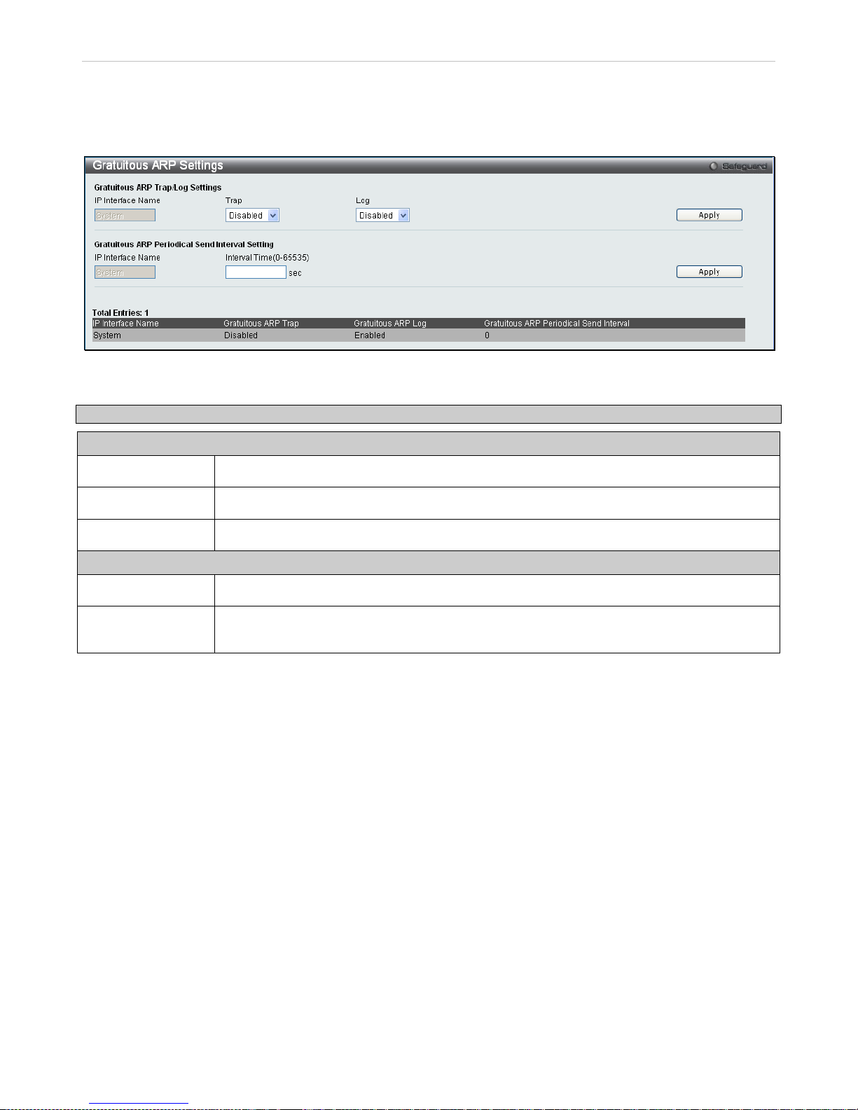
xStack® DES-3200 Series Layer 2 Ethernet Managed Switch WEB UI Reference Guide
57
Gratuitous ARP Settings
This window allows you to have more detailed settings for the Gratuitous ARP.
To view this window, click Configuration > Gratuitous ARP > Gratuitous ARP Settings:
Figure 2 - 60. Gratuitous ARP Settings window
The following fields can be set or viewed:
Parameter Description
Gratuitous ARP Trap/Log
Trap
The switch can trap IP conflict events to inform the administrator. By default, trap is Disabled.
Log
The switch can log IP conflict events to inform the administrator. By default, Log is Enabled.
IP Interface Name
Displays the name of the interface that is being edited.
Gratuitous ARP Periodical Send Interval
IP Interface Name
Displays the name of the interface that is being edited.
Interval Time (0-
65535)
This is used to configure the interval for the periodical sending of gratuitous ARP request
packets. By default, the interval is 0.
Click Apply to implement changes made.
Page 59
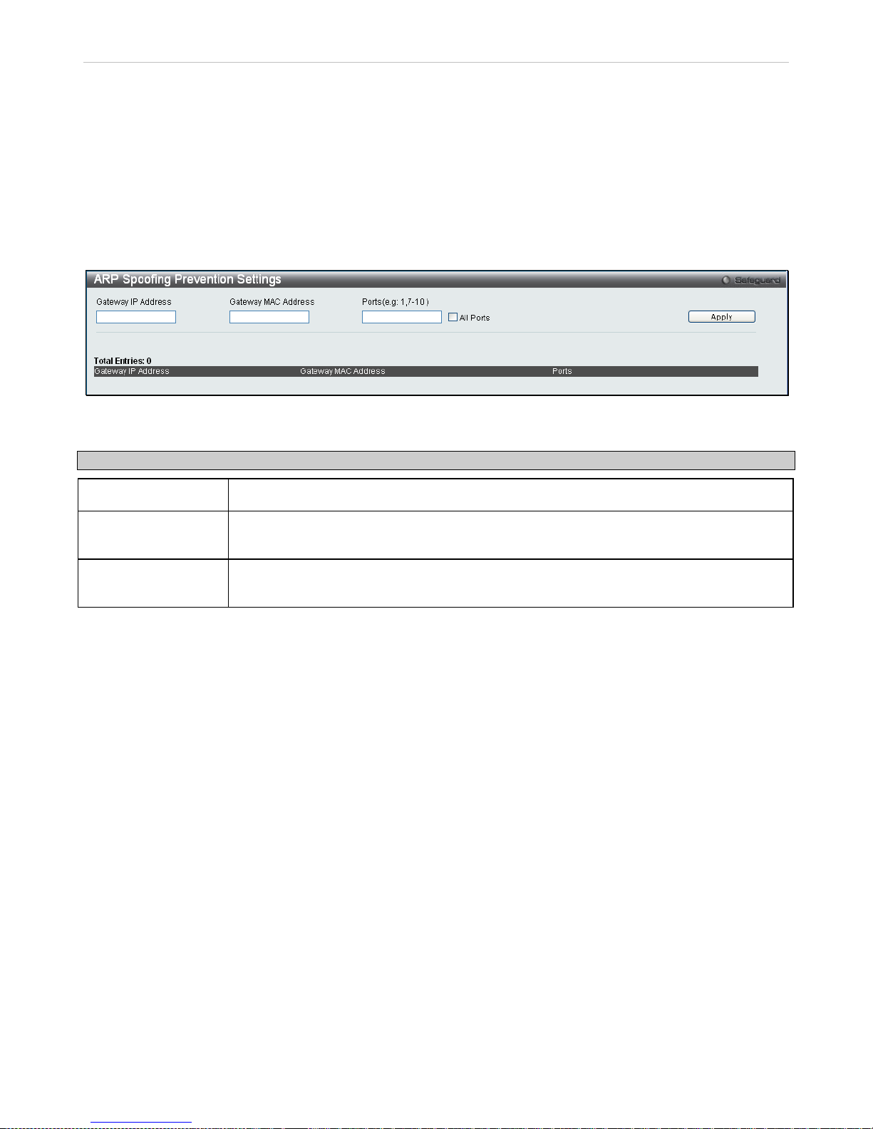
xStack® DES-3200 Series Layer 2 Ethernet Managed Switch WEB UI Reference Guide
58
ARP Spoofing Prevention Settings
ARP spoofing, also k nown as ARP po isoning, is a method t o attack an Ethernet n etwork which m ay allow an attac ker
to sniff data fram es on a LAN, modify the traf fic, or stop the traffic altogether (known as a Denial of Service - DoS
attack). The principle of ARP spoofing is to send the fake or spoofed ARP messages to an Ethernet network.
Generally, the aim is to as sociate t he attacker's or random MAC addr es s w ith th e IP addres s of another n od e (s uc h as
the default gateway). An y traffic meant for that IP address would be m istakenly re-directed to th e node specified by
the attacker.
To prevent ARP spoofing attack , the switch us es Packet Content ACL t o block the invalid AR P pack ets which c ontain
faked gateway’s MAC and IP binding.
To view this window, click Configuration > ARP Spoofing Prevention Settings as shown below:
Figure 2 - 61. ARP Spoofing Prevention Settings window
The following fields can be set or viewed:
Parameter Description
Gateway IP Address
Enter the IP address of the gateway.
Gateway MAC
Address
Enter the MAC address of the gateway.
Ports (e.g.: 1, 7-10)
Specify the switch ports f or which to configure the ARP Spoofin g Prevention settings. Tick
the All Ports check box to configure this entry for all ports on the Switch.
Click Apply to implement changes made.
Page 60
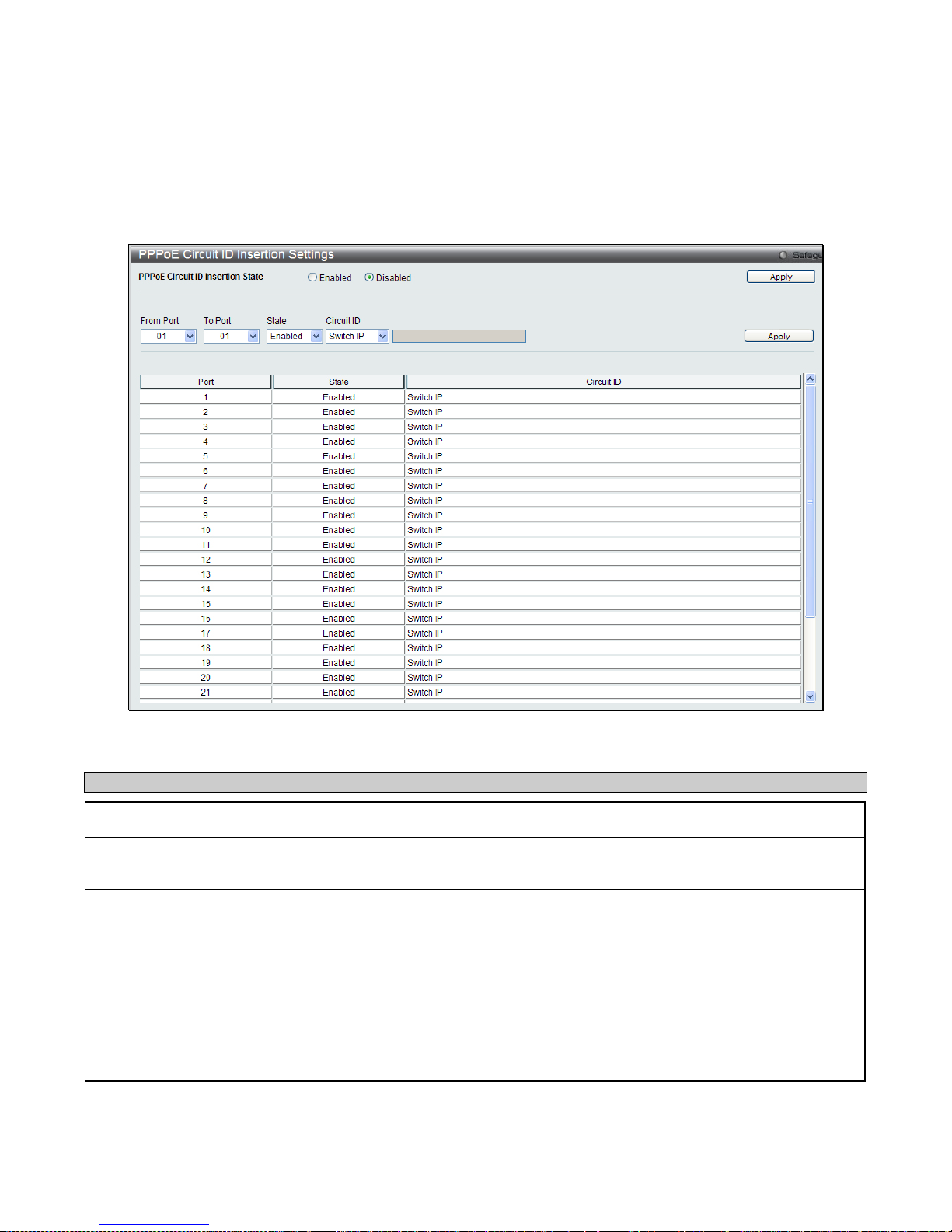
xStack® DES-3200 Series Layer 2 Ethernet Managed Switch WEB UI Reference Guide
59
PPPoE Circuit ID Insertion Settings
When the setting is enabled, the system will insert t he circuit ID tag to the received PPPoE discover and request
packet if the tag is abs ent, and remove the circuit ID tag from the received PPPoE off er and session confirmation
packet. The insert c ircuit ID will con tain the following information: Cli ent MAC address, Dev ice ID and Port number.
Additionally, the opt ion of user defined str i ngs c an be inserted int o t he c irc uit I D. B y def au lt, S witc h IP ad dr e s s is used
as the device ID to encode the circuit ID option.
To view this window, click Configuration > PPPoE Circuit ID Insertion Settings as shown below
Figure 2 - 62. PPPoE Circuit ID Insertion
The following fields can be set or viewed:
Parameter Description
From Port – To Port:
Specify the ports to be configured.
State: Choose Enable or Disable to enable or disable PPPoE circ uit ID insertion on the selected
ports.
Circuit ID:
Choose the device ID used for encoding of the circuit ID option. The available options are:
• Switch MAC – Spec ifies th at the S witch M AC addr ess be us ed to encode the circ uit
ID option.
• Switch IP – Specifies that the Switch IP address be used t o encode the circuit ID
option.
• UDF String – A user defined string to be used to enc ode the circuit ID option. The
maximum length is 32.
The default encoding for the device ID option is the Switch IP address.
Click Apply to implement changes made.
Page 61
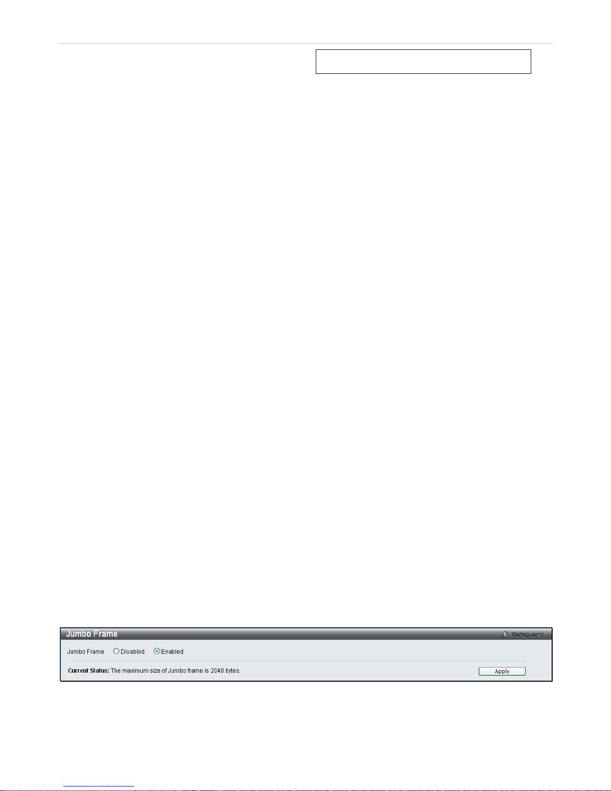
xStack® DES-3200 Series Layer 2 Ethernet Managed Switch WEB UI Reference Guide
60
Section 3
L2 Features
Jumbo Frame
802.1Q Static VLAN
Q-in-Q
802.1v Protocol VLAN
VLAN Trunk Settings
GVRP Settings
Asymmetric VLAN Settings
MAC-based VLAN Settings
PVID Auto Assign Settings
Port Trunking
LACP Port Settings
Traffic Segmentation
Layer 2 Protocol Tunneling Settings
IGMP Snooping
MLD Snooping Settings
Port Mirror
Loopback Detection Settings
Spanning Tree
Forwarding & Filtering
LLDP
Ethernet OAM
Connectivity Failure Management
ERPS Settings
The following sectio n will aid the user in configuring Layer 2 functions for the Switch. T he Switch includes various
functions all discussed in detail in the following section.
Jumbo Frame
This window will enable or disab le the Jumbo Fram e function on the Switch. The default is Enabled. W hen Ena bled,
jumbo frames (fr am es lar ge r than the standard Eth erne t f ram e s i ze of 1 53 6 bytes) with a maximum size of 20 48 b ytes
can be transmitted by the Switch.
To view this window, click L2 Features > Jumbo Frame:
Figure 3 - 1. Jumbo Frame window
Click Apply to implement changes made.
Page 62

xStack® DES-3200 Series Layer 2 Ethernet Managed Switch WEB UI Reference Guide
61
VLANs
Understanding IEEE 802.1p Priority
Priority tagging is a func tio n defined by the IEEE 80 2.1p s tandar d desig ned to pr ov ide a m eans of managin g traf fic on
a network where m any different types of data may be trans mitted simulta neously. It is intended to alle viate problems
associated with the delivery of time critical data over congested networks. The quality of applications that are
dependent on such tim e critical data, such as video conferencing, c an be severely and adversely affected b y even
very small delays in transmission.
Network devices that are in compliance with the IEEE 802.1p standard have the ability to recognize the priority level of
data packets. These dev ice s c an also as sign a pr ior it y lab el or ta g to p ac kets. Compliant devices c an a lso s t r ip prior ity
tags from packets. This priority tag determines the pa cket's degree of expediti ousness and determines the queue to
which it will be assigned.
Priority tags are given values from 0 to 7 with 0 being assigned to the lowest priority data and 7 assigned to the
highest. The highest prior ity tag 7 is generally only used for data as sociated with video or audio applic ations, which
are sensitive to e ven slight delays, or for data fr om specified end users whose dat a transmissions warrant spec ial
consideration.
The Switch allows you to further ta il or h o w prior ity tagged data pac kets are handled on your network. Using queues to
manage priority tagged data allows you to specify its relat ive priorit y to suit the needs of your network . There m ay be
circumstances where it would be adva ntageous to gr oup two or m ore diff erently tagge d packets into the same queue.
Generally, however, it is r ecommended tha t the highest priorit y queue, Queue 7, be res erved for data pack ets with a
priority value of 7. Pack ets that have not been given any priority value are placed in Queue 0 and thus given the
lowest priority for delivery.
Strict mode and weigh ted round robin system are emplo yed on the Switch to det ermine the r ate at which t he queues
are emptied of packets . The ratio used for clearing the queues is 4:1. T his means that the highest priority queue ,
Queue 7, will clear 4 packets for every 1 packet cleared from Queue 0.
Remember, the priori ty queue set tings on t he Switch a re for all por ts, and all devices connec ted to the Switch w ill be
affected. This priorit y queuing system will be especia lly benef icial if your network employs switches with the c apability
of assigning priority tags.
VLAN Description
A Virtual Local Are a Network (VLAN) is a network topology configur ed according to a logical sc heme rather tha n the
physical layout. VLANs can be used to combine a ny collection of LAN segm ents into an autonom ous user g roup that
appears as a single LAN. VL ANs also logical ly segment th e network into diff erent broadcas t domains so th at packets
are forwarded only bet wee n por ts with in t he VL AN. Typically, a VLAN c or res p ond s to a p ar ticu lar s ub net, although not
necessarily.
VLANs can enhance performance by conserving bandwidth, and improve security by limiting traffic to specific
domains.
A VLAN is a collection of end nodes grouped by logic instead of physical location. End nodes that frequently
communicate with each other are assigned to the same VLAN, regardless of where they are physically on the
network. Logicall y, a VLAN can b e equa ted to a br oadcas t domain, b ecause br oadcast pac kets ar e forwarde d to onl y
members of the VLAN on which the broadcast was initiated.
Notes About VLANs
No matter what basis is used to uniquely identify end nodes a nd assign these nodes VLAN m embership, pack ets
cannot cross VLANs without a network device performing a routing function between the VLANs.
The Switch supports IEEE 802.1Q VLANs and Port-Based VLANs. The port untagging function can be used to
remove the 802.1Q tag from packet headers to maintain compatibility with devices that are tag-unaware.
The Switch's default is to assign all ports to a single 802.1Q VLAN named "default."
The "default" VLAN has a VID = 1.
The member ports of Port-based VLANs may overlap, if desired.
Page 63
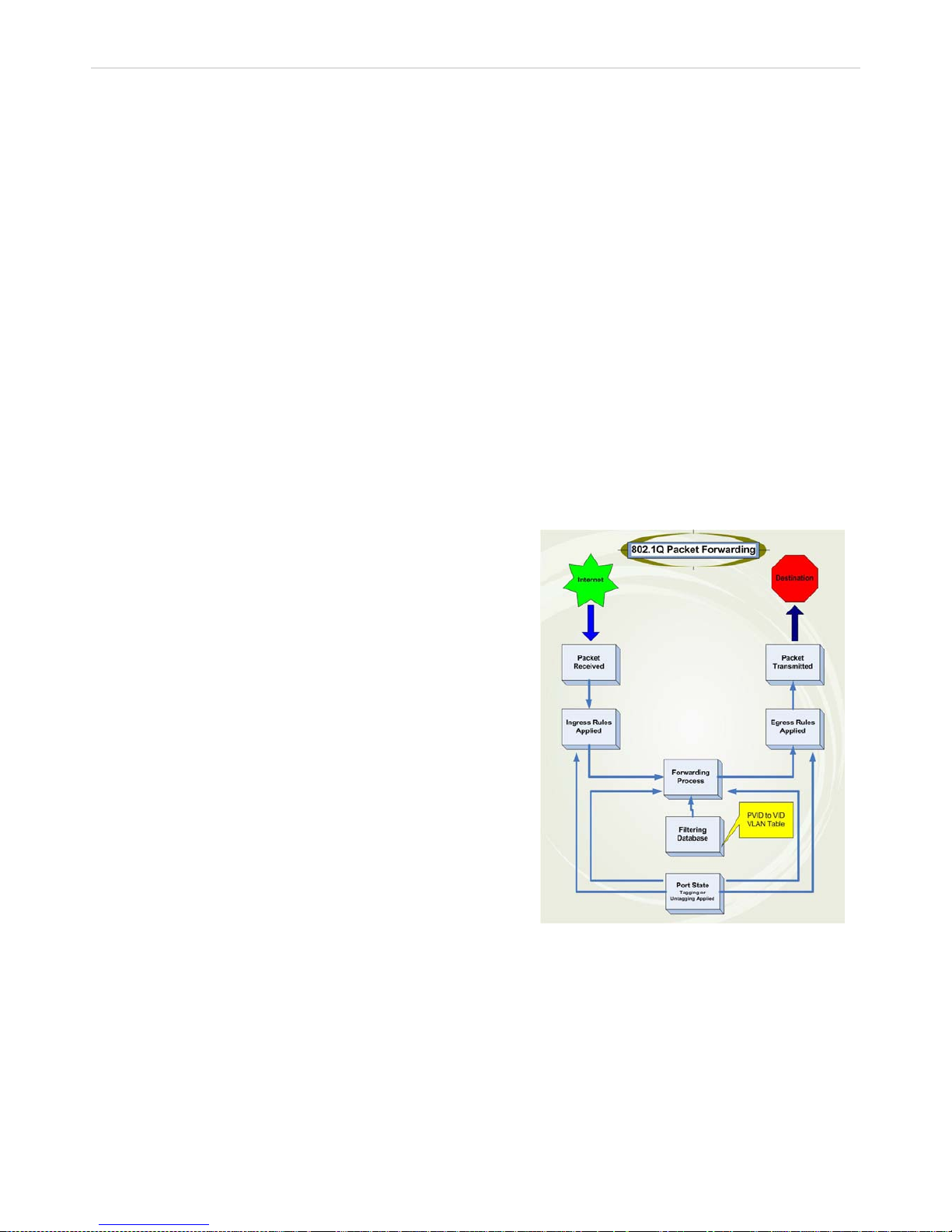
xStack® DES-3200 Series Layer 2 Ethernet Managed Switch WEB UI Reference Guide
62
IEEE 802.1Q VLANs
Some relevant terms:
Tagging - The act of putting 802.1Q VLAN information into the header of a packet.
Untagging - The act of stripping 802.1Q VLAN information out of the packet header.
Ingress port - A port o n a switch where pack ets are flowing into t he Switch and VLAN d ecisions must be
made.
Egress port - A port on a switch where pac kets ar e flowing out of the S witch, eit her to another sw itch or to
an end station, and tagging decisions must be made.
IEEE 802.1Q (tagged) VLA Ns are im plem ented on th e S witch. 802.1Q VL ANs req uire tag ging, which enab les them to
span the entire network (assuming all switches on the network are IEEE 802.1Q-compliant).
VLANs allow a networ k to be segmented in order to reduce the size of broadcast domains. All packets entering a
VLAN will only be forwarded to the stations (over IEEE 802.1Q enabled switches) that are members of that VLAN, and
this includes broadcast, multicast and unicast packets from unknown sources.
VLANs can also pro vide a level of security to your network. IEEE 802.1Q VLA Ns will only deliver pack ets between
stations that are members of the VLAN.
Any port can be configured as either tagging or untagging. The untagging feature of IEEE 802.1Q VLANs allows
VLANs to work wit h legacy switches that don't r ecognize VLAN tags in p acket headers. The tagging feature allows
VLANs to span multiple 802.1Q-compliant switc hes th rough a s ingle p hysic al connec tion an d allows Spann ing T ree to
be enabled on all ports and work normally.
The IEEE 802.1Q standard r estricts the forwarding of unta gged packets to the VLAN of which the receiving port is a
member.
Figure 3 - 2. IEEE 802.1Q Packet Forwarding
802.1Q VLAN Tags
The figure below shows the 802.1Q VLAN tag. There are four additional octets inserted after the source MAC
address. Their presenc e is indicated b y a value of 0x8100 in the EtherType fie ld. When a packet' s EtherType field is
equal to 0x8100, the packet c arries the IEEE 802.1Q/ 802.1p tag. T he tag is contained in the f ollowing two o ctets and
consists of three bits of us er priority, one bit of Canonical Form at Identifier (CFI - used for encapsul ating Token Ring
packets so they can be c arried ac ross Ethernet backbones), a nd twelve b its of VLAN ID (VID). The thr ee bits of user
priority are used by 802.1p . The VID is the VLAN i dentifier and is used b y the 802.1Q standard. B ecause the VID is
twelve bits long, 4094 unique VLANs can be identified.
The main characteristics of IEEE 802.1Q are as follows:
Assigns packets to VLANs by filtering.
Assumes the presence of a single global
spanning tree.
Uses an explicit taggin g scheme with one-level
tagging.
802.1Q VLAN Packet Forwarding
Packet forwarding decisions are made based
upon the following three types of rules:
Ingress rules - ru les re leva nt to the c lass ificatio n
of received frames belonging to a VLAN.
Forwarding rules between ports - decides
whether to filter or forward the packet.
Egress rules - deter mines if the pac ket must be
sent tagged or untagged.
Page 64
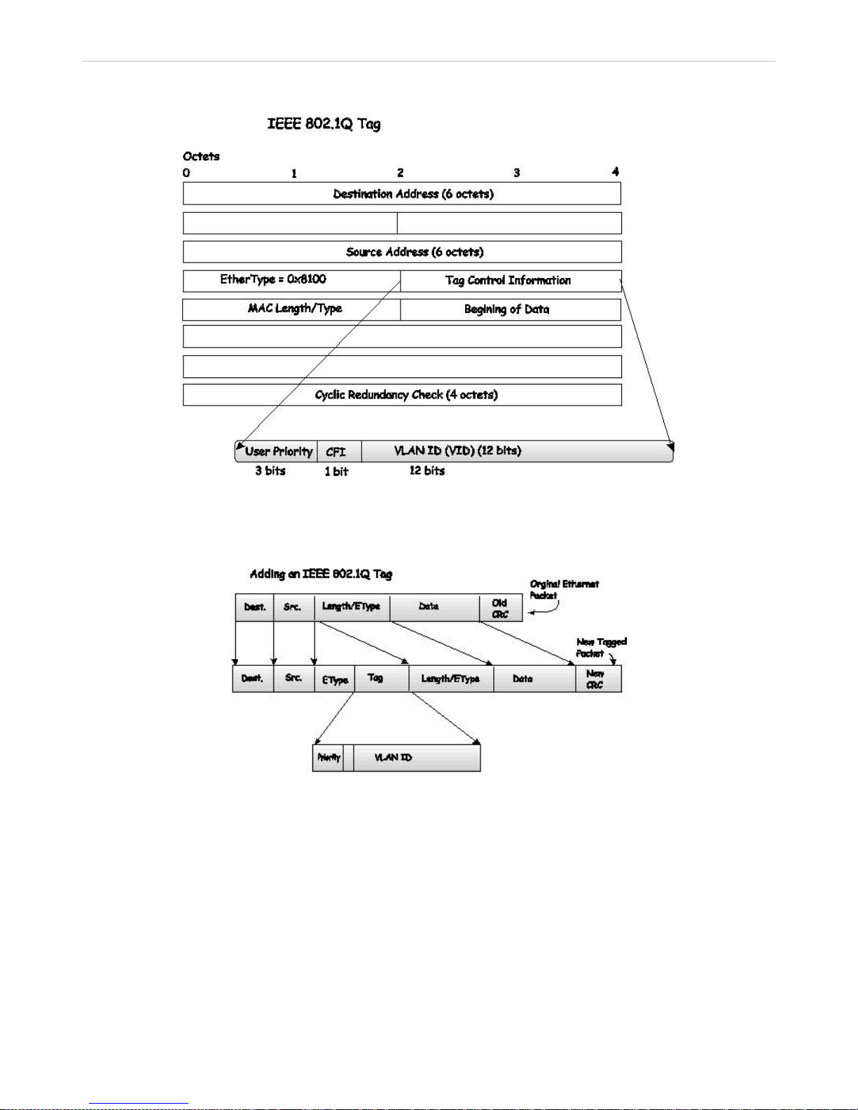
xStack® DES-3200 Series Layer 2 Ethernet Managed Switch WEB UI Reference Guide
63
The tag is inserted into the packet header making the entire packet longer by four octets. All of the information
originally contained in the packet is retained.
Figure 3 - 3. IEEE 802.1Q Tag
The EtherType and VL AN ID are inserted af ter the MAC s ource address , but befo re the origina l EtherT ype/Length or
Logical Link Control. Because the packet is now a bit longer than it was originally, the Cyclic Redundancy Check
(CRC) must be recalculated.
Figure 3 - 4. Adding an IEEE 802.1Q Tag
Port VLAN ID
Packets that are tagge d (are carrying the 802.1Q VID information) can be tra nsmitted from one 802.1Q compliant
network device to anot her with the VLAN inform ation intac t. This a llows 8 02.1Q VL ANs to s pan net work de vices (and
indeed, the entire network, if all network devices are 802.1Q compliant).
Unfortunately, not all net work devices are 802. 1Q compliant. These de vices are referred to as t ag-unaware. 802.1Q
devices are referred to as tag-aware.
Prior to the adoption of 802.1Q VLANs, port-based and MAC-based VLANs were in common use. These VLANs relied
upon a Port VLAN ID (PVID) to forward packets. A packet received on a given port would be assigned that port's PVID
and then be forwarded to the port that corresponded to the packet's destination address (found in the Switch's
forwarding table). If the PVID of the port that received the packet is different from the PVID of the port that is to
transmit the packet, the Switch will drop the packet.
Page 65

xStack® DES-3200 Series Layer 2 Ethernet Managed Switch WEB UI Reference Guide
64
Within the Switch, differ ent PVIDs mean dif ferent VLANs ( remember that two VL ANs cannot comm unicate without a n
external router). So, VLAN identification based upon the PVIDs cannot create VLANs that extend outside a given
switch (or switch stack).
Every physical port on a s witch has a PVID. 802.1Q ports are also assigned a PVID, for use within the Switch. If no
VLANs are defined on the S witch, all ports are then assigned to a def ault VLAN with a PVID equal to 1. Untagged
packets are assigned the PVI D of the port on which they were receive d. Forwarding decisions are based upon t his
PVID, in so far as VLANs are concerned. Tagged pack ets are forwarded according to the VID contained within the
tag. Tagged packet s are also assigned a PVID, but the P VID is not used to make pack et-forwarding decisions, the
VID is.
Tag-aware switches m ust keep a table to relate PVIDs within the Switch to VIDs on the network. The Switch will
compare the VID of a pac ket to be tr ansm itted to the VID of the port t hat is to tr ansm it the pack et. If the two VIDs are
different, the Switch will drop the pac ket. Because of the existenc e of the PVID for untagged packets and t he VID for
tagged packets, tag-aware and tag-unaware network devices can coexist on the same network.
A switch port can have only one PVID , but can have as m any VIDs as the S witch has memor y in its VLAN table to
store them.
Because some devices o n a network may be tag-unaware, a decis ion must be made at each port on a tag-aware
device before packets are transm itted - should the pack et to be transmitted ha ve a tag or not? If the transmitting port
is connected to a t ag-unaware devic e, the packet s hould be untagged. If the transm itting port is connect ed to a tagaware device, the packet should be tagged.
Tagging and Untagging
Every port on an 802.1Q compliant switch can be configured as tagging or untagging.
Ports with tagging e nabled w ill put the VID num ber, prior ity and other VLAN inform ation into the h eader of all packets
that flow into and out of it. If a pack et has previously been tagg ed, the port will not alter the p acket, thus keeping th e
VLAN information intact. O ther 802.1Q compliant devices on the network to make packet-forwarding decisions can
then use the VLAN information in the tag.
Ports with untagging enabled will strip the 802.1Q ta g from all packets that flow into and out of those ports. If the
packet doesn't have an 802.1Q VLAN tag, the port will not alter the packet. Thus, all packets received by and
forwarded by an untagging port will have no 802.1Q VLAN information. (Remember that the PVID is only used
internally within the Switch). Untagging is used to send packets from an 802.1Q-compliant networ k device to a noncompliant network device.
Ingress Filtering
A port on a switch where p ackets are flowing in to the Switch and VL AN decisions m ust be made is referr ed to as an
ingress port. If ingress filtering is enabled for a port, the Switch will examine the VLAN information in the packet
header (if present) and decide whether or not to forward the packet.
If the packet is t agged with VLAN inf ormat ion, th e ingr ess por t wi ll f irst det erm ine if the in gress port itself is a m em ber
of the tagged VLAN. If it is not, the packet will be dro pped. If the ingress port is a member of the 802.1Q V LAN, the
Switch then determ ines if the destination port is a mem ber of the 802.1Q VLAN. If it is not, the packet is dropped. If
the destination port is a member of th e 802.1Q VLAN, the pack et is forwarded an d the destina tion port transm its it to
its attached network segment.
If the packet is not tagged with VLAN information, the ingress port will tag the packet with its own PVID as a VID (if the
port is a tagging port). T he switch then determines if the destin ation port is a member of the sam e VLAN (has the
same VID) as the ingress port. If it does not, the packet is dropped. If it has the same VID, the packet is forwarded and
the destination port transmits it on its attached network segment.
This process is referred to as ingress filtering and is used to conserve bandwidth within the Switch by dropping
packets that are not on the sam e VLAN as the ingress port at the point of reception. T his eliminates t he subseque nt
processing of packets that will just be dropped by the destinat ion por t.
Default VLANs
The Switch initiall y configur es one VLAN, VID = 1, c alled "def ault." T he factor y default s etting ass igns a ll ports on t he
Switch to the "default." As new VLANs ar e config ur ed in Port -based mode, their respective member ports are removed
from the "default."
Page 66

xStack® DES-3200 Series Layer 2 Ethernet Managed Switch WEB UI Reference Guide
65
Packets cannot cross VLANs. If a mem ber of one VLAN want s to connect to another VLAN, th e link mus t be through
an external router.
NOTE: If no VLANs are c onfigured on the S witch, then all packets will be forwarded to an y
destination port. Packets with unknown source addresses will be flooded to all ports.
Broadcast and multicast packets will also be flooded to all ports.
An example is presented below:
VLAN Name VID Switch Ports
System (default) 1 5, 6, 7, 8, 21, 22, 23, 24
Engineering 2 9, 10, 11, 12
Marketing 3 13, 14, 15, 16
Finance 4 17, 18, 19, 20
Sales 5 1, 2, 3, 4
Table 3 - 1. VLAN Example - Assigned Ports
Port-based VLANs
Port-based VLANs limit traffic that flows into and out of switch ports. Thus, all devices connected to a port are
members of the VLAN(s ) the port belongs to, wheth er there is a s ingle com puter directly co nnected t o a swit ch, or an
entire department.
On port-based VLANs, NIC s do not n eed to be able to identif y 802.1Q tags in pac k et headers. NI Cs send a nd r eceive
normal Ethernet packets. If the packet's destination lies on the same segment, communications take place using
normal Ethernet prot ocols. Even though this is alwa ys the case, when the destination f or a packet lies on another
switch port, VLAN considerations come into play to decide if the packet gets dropped by the Switch or delivered.
VLAN Segmentation
Take for example a pack et that is transm itted by a machine on Port 1 that is a m ember of VLAN 2. If the destination
lies on another port (found through a normal forwarding ta ble lookup), the Switch then lo oks to see if the other port
(Port 10) is a mem ber of V LAN 2 (a nd can ther efore r eceive VL AN 2 pac kets) . If Port 10 is not a m ember of VLAN 2,
then the packet wil l be dr opped b y the S witch and will not reac h its desti nation . If Por t 10 is a m em ber of VLAN 2, the
packet will go throu gh. This selective forwardi ng feature based on VLAN cr iteria is how VLANs segm ent networks.
The key point being that Port 1 will only transmit on VLAN 2.
Network resources c an b e s har ed acr os s VL ANs . This is achieved by setting up overl app in g VL ANs . T hat is ports can
belong to more than one VLAN gro up. For example, by setting V LAN 1 members to ports 1, 2, 3 an d 4 and VLAN 2
members to ports 1, 5, 6 and 7, Port 1 will belong to two VLAN groups. Ports 8, 9 and 10 are not configured to an y
VLAN group. This means ports 8, 9 and 10 are in the same VLAN group.
VLAN and Trunk Groups
The members of a trunk group have the sam e VLAN s etting. Any VLAN setting on the m embers of a trunk group will
apply to the other member ports.
NOTE: In order to us e VLAN segmentation in conjun ction with port trunk groups, you can first
set the port trunk group(s), and the n you may configure VLAN setti ngs. If you wish to change
the port trunk grouping with VL ANs already in plac e, you will not need t o reconfigure the VL AN
settings after changi ng the por t trunk gr oup sett ings. V LAN s ettings will autom atic ally ch ange in
conjunction with the change of the port trunk group settings.
Q-in-Q VLANs
Q-in-Q VLANs (also sometimes referred to as double VLANs) allow network providers to expand their VLAN
configurations to place customer VLANs within a larger inclusive VLAN, which adds a new layer to the VLAN
configuration. This bas ically lets large ISP's create L2 Virtual Pri vate Networks and also c reate transparent LANs for
Page 67
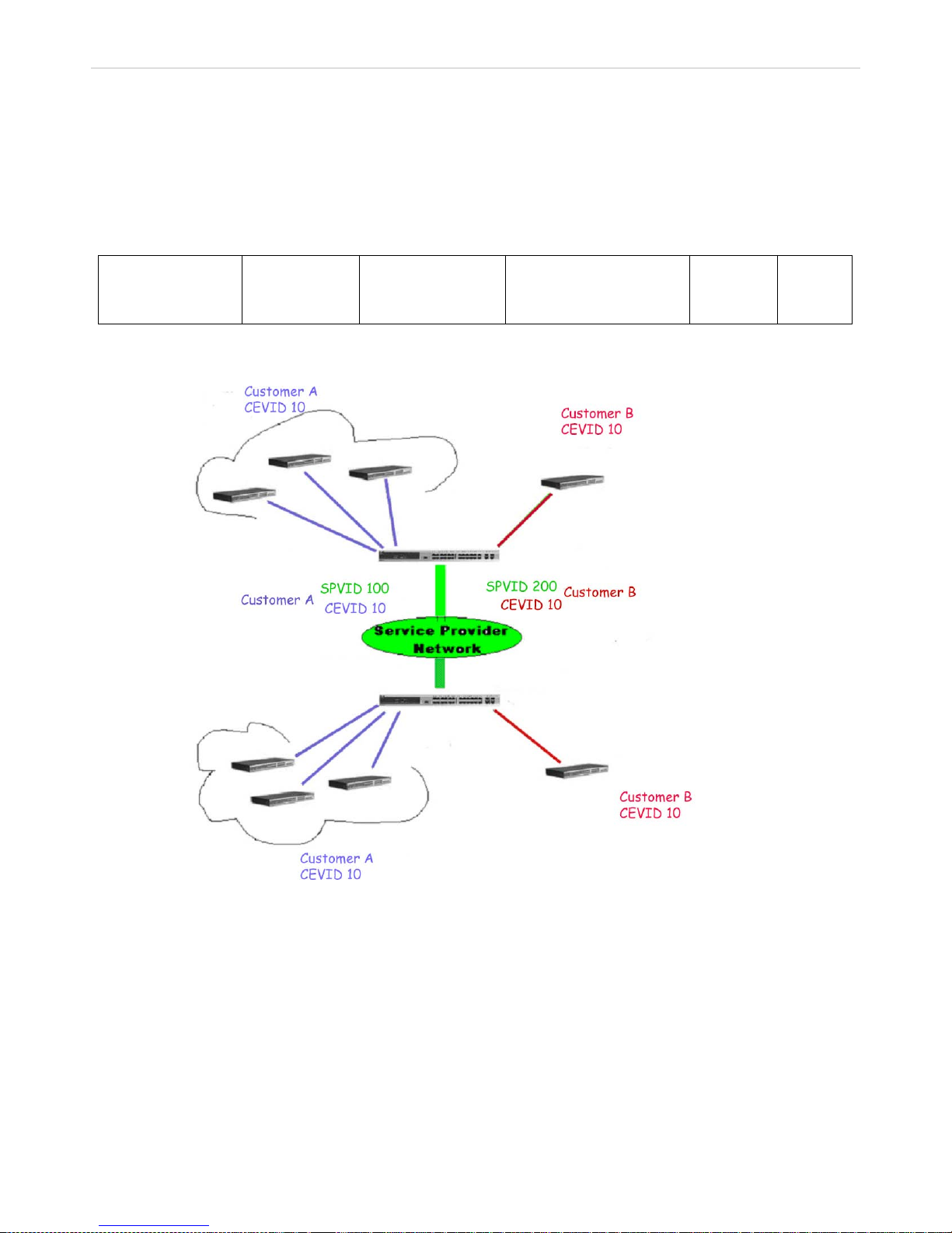
xStack® DES-3200 Series Layer 2 Ethernet Managed Switch WEB UI Reference Guide
66
their customers, which will connect t wo or more cus tomer LAN points without ov er-complic ating configurat ions on the
client's side. Not on ly will over-complicatio n b e a vo id e d, bu t a ls o n o w the administrator has over 4000 VLANs in which
over 4000 VLANs can be placed, therefore greatly expanding the VLAN network and enabling greater support of
customers utilizing multiple VLANs on the network.
Q-in-Q VLANs are basically VL AN ta gs p laced withi n e x is ting IE EE 8 02.1Q VLANs which we will c al l S PVID s ( Ser vic e
Provider VLAN IDs). These VLANs are marked by a TPID (Tagged Protocol ID), configured in hex form to be
encapsulated within the VL AN tag of the packet. This identif ies the packet as double-tagged and segr egates it from
other VLANs on the network, therefore creating a hierarchy of VLANs within a single packet.
Here is an example Q-in-Q VLAN tagged packet:
Destination
Address
Source
Address
SPVLAN (TPID +
S
ervice Provider
VLAN Tag)
802.1Q CEVLAN Tag
(TPID + Customer VLAN
Tag)
Ether
Type
Payload
Consider the example below:
Figure 3 - 5. Q-in-Q VLAN Example
In this example, the Service Provider Access Network switch (Provider edge switch) is the device creating and
configuring Q-in-Q VLANs with different SPVIDs for specific customers (say Customer A and Customer B). Both
CEVLANs (Customer VLANs), CEVLAN 10 are tagged with the SPVID 100 (for Customer A) or SPVID 200 (for
Customer B) on the Servic e Provider Access Netw ork, thus be ing a mem ber of two VL ANs on the Ser vice Prov ider’s
network. In this wa y, the Custom er can retain the ir normal VL AN ID’s and t he Service Pro vider can separate multiple
Customer VLANs using SPVLANs, thus greatly regulating traffic and routing on the Service Provider switch. This
information is then route d to the Service Provider’s main n etwork and regarded there as one VL AN, with one set of
protocols and one routing behavior.
Regulations for Q-in-Q VLANs
Some rules and regulations apply with the implementation of the Q-in-Q VLAN procedure.
Page 68
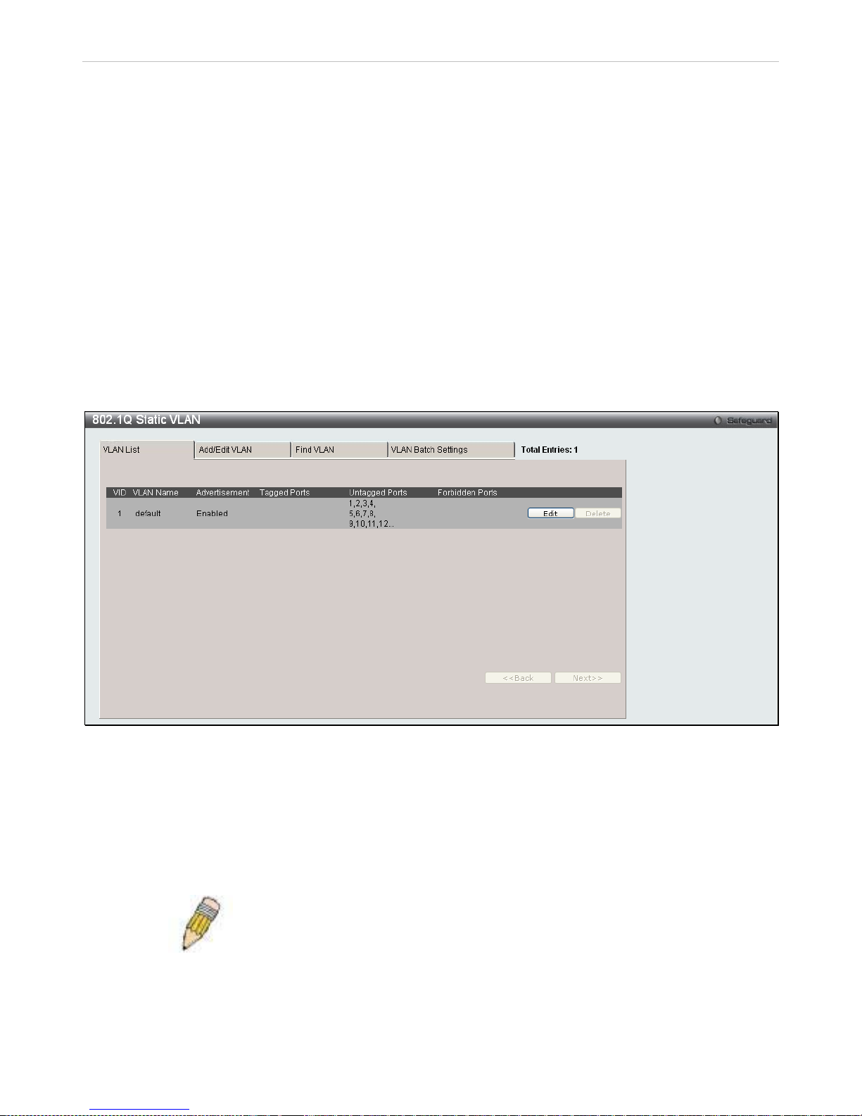
xStack® DES-3200 Series Layer 2 Ethernet Managed Switch WEB UI Reference Guide
67
1. All ports must be configured for the SPVID and its corresponding TPID on the Service Provider’s edge switch.
2. All ports must be configured as Access Ports or Uplink ports. Ac c ess ports can on l y be Ethernet por ts wh ile
Uplink ports must be Gigabit ports.
3. Provider Edge switches must allow frames of at least 1522 bytes or more, due to the addition of the SPVID
tag.
4. Access Ports must be an un-tagged port of the service provider VLANs. Uplink Ports must be a tagged port of
the service provider VLANs.
5. The switch cannot have both Q-in-Q and normal VLANs co-existing. Once the change of VLAN is made, all
Access Control lists are cleared and must be reconfigured.
6. Before Q-in-Q VLANs are enabled, users need to disable STP and GVRP manually.
7. All packets sent from the CPU to the Access ports must be untagged.
802.1Q Static VLAN
This window lists all previously configured VLANs by VLAN ID and VLAN Name.
To view this window, click L2 Features > 802.1Q Static VLAN:
Figure 3 - 6. 802.1Q Static VLAN window - VLAN List tab
To create a new 802.1Q VLAN entry, click the Add/Edit VLAN tab at the top of the window. A new tab wi ll appe ar, as
shown in the first figure o n the next page, to c onfigure the por t settings and to assign a unique nam e and num ber to
the new VLA N.
To edit an existing 802.1Q VLAN entry, clic k the Edit butto n next to the corr esponding VLA N entry above. A new tab
will appear, as shown in the second figure on the next page.
See the table on the nex t page for a description of the parameters of the 802.1Q Static VLAN window’s Add/Edit
VLAN tab.
NOTE: After all IP interfaces are set for configurations, VLANs on the
Switch can be routed without any additional steps.
Page 69
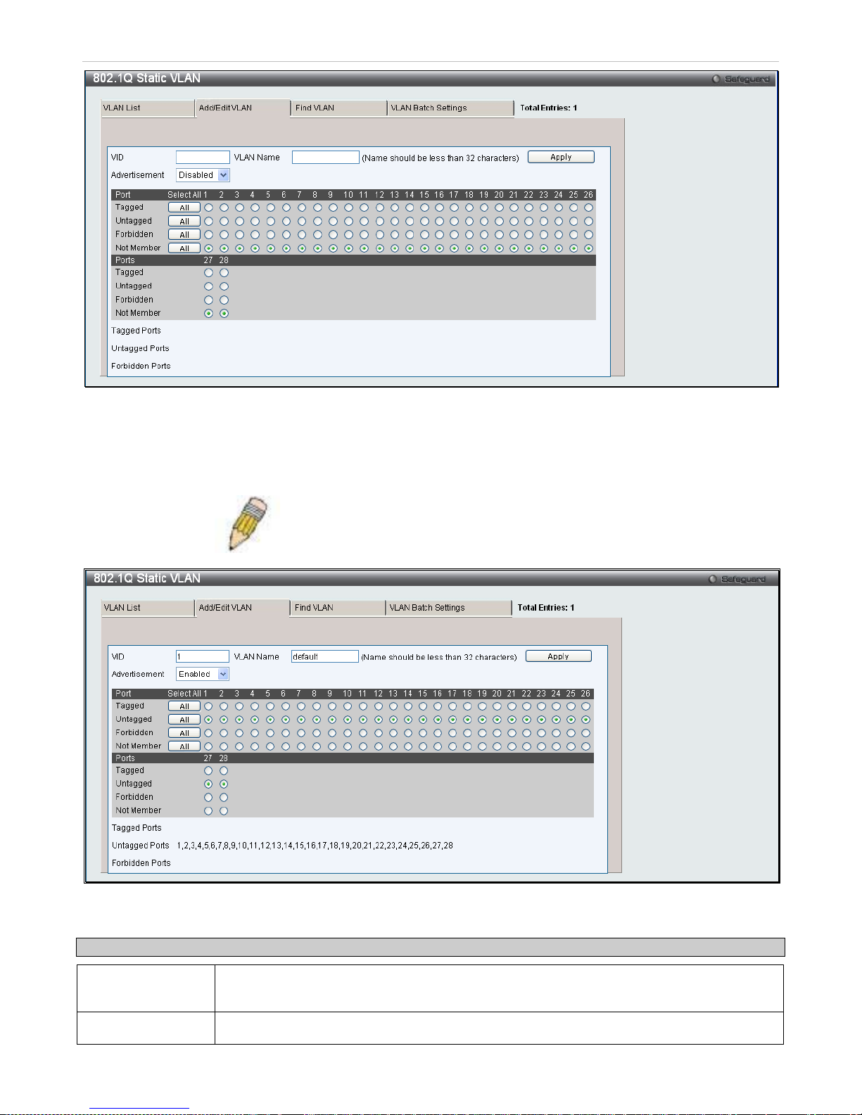
xStack® DES-3200 Series Layer 2 Ethernet Managed Switch WEB UI Reference Guide
68
Figure 3 - 7. 802.1Q Static VLAN window – Add/Edit VLAN tab (Add)
To return to the initial 802.1Q Static VLAN window, click the VL AN Lis t tab at the top of the window. T o change an
existing 802.1Q static V LA N ent ry, click the corres pon din g Edit button. A new windo w will appear to conf igur e the port
settings and to as sign a unique name and num ber to the new VLAN. See the tab le below for a description of t he
parameters in the new window.
NOTE: The Switch supports up to 4k static VLAN entries.
Figure 3 - 8. 802.1Q Static VLAN window – Add/Edit VLAN tab (Edit)
The following fields can then be set in the Add/Edit VLAN tab:
Parameter Description
VID (VLAN ID) Allows the entry of a VLAN ID, or displays the VLAN ID of an existing VLAN in the Edit
window. VLANs can be identified by either the VID or the VLAN name.
VLAN Name Allows the entry of a name for a new VLAN, or modif ying the VLAN name in t he Edit window.
Page 70
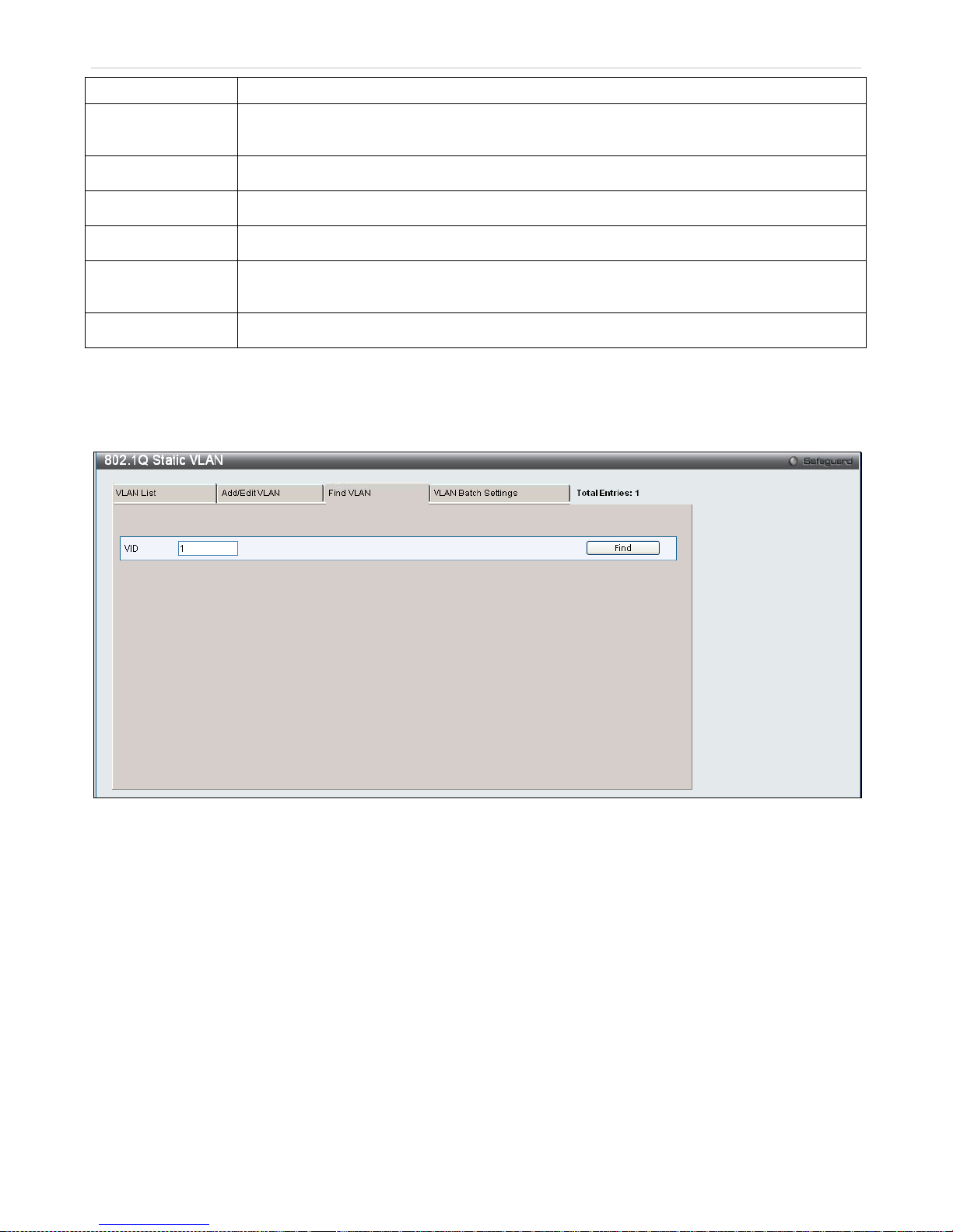
xStack® DES-3200 Series Layer 2 Ethernet Managed Switch WEB UI Reference Guide
69
VLAN Name should be no more than 32 characters in length.
Advertisement
Enabling this function will allow the Switch to send out GVRP packets to outside sources,
notifying that they may join the existing VLAN.
Port Settings
Allows an individual port to be specified as member of a VLAN.
Tagged
Specifies the port as 802.1Q tagged. Checking the box will designate the port as Tagged.
Untagged
Specifies the port as 802.1Q untagged. Checking the box will designate the port as untagged.
Forbidden
Select this to specify the port as not being a member of the VLAN and that the port is
forbidden from becoming a member of the VLAN dynamically.
Not Member
Allows an individual port to be specified as a non-VLAN member.
Click Apply to implement changes made.
To search for a VLAN, click the Find VL AN tab at the top of the wind ow (s ee below), e nter a VLAN ID, and cl ick Find
to display the settings for a previously configured VLAN.
Figure 3 - 9. 802.1Q Static VLAN window – Find VLAN tab
To create a VLAN Batch e ntry, click the VLAN Batch Settings tab at the top of the windo w, which will display the
following window:
Page 71
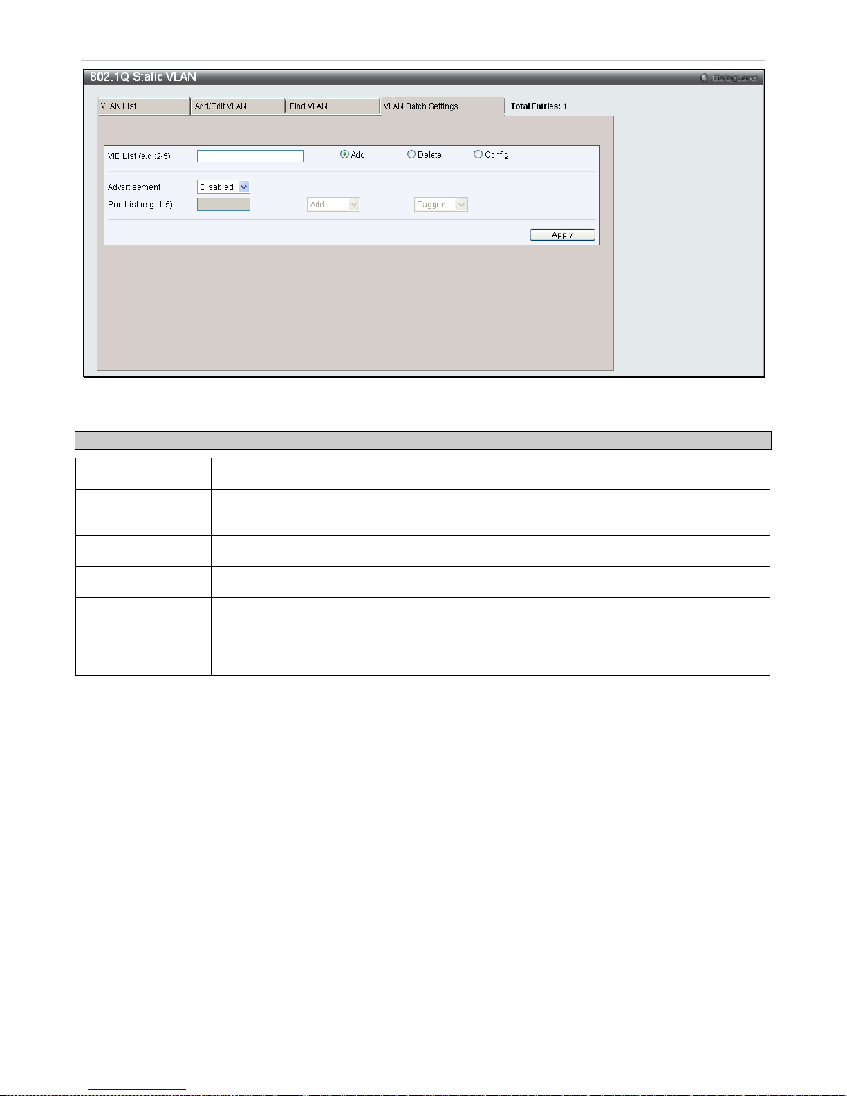
xStack® DES-3200 Series Layer 2 Ethernet Managed Switch WEB UI Reference Guide
70
Figure 3 - 10. 802.1Q Static VLAN window – VLAN Batch Settings tab
The following fields can be set in the VLAN Batch Settings tab:
Parameter Description
VID List (e.g.: 2-5)
Enter a VLAN ID List that can be added, deleted or configured.
Advertisement
Enabling this function will allow the Switch to send out GVRP packets to outside sources,
notifying that they may join the existing VLAN.
Port List (e.g.: 1-5)
Allows an individual port list to be added or deleted as a member of the VLAN.
Tagged
Specifies the port as 802.1Q tagged. Checking the box will designate the port as Tagged.
Untagged
Specifies the port as 802.1Q untagged. Checking the box will designate the port as untagged.
Forbidden
Select this to specify the port as not being a member of the VLAN and that the port is
forbidden from becoming a member of the VLAN dynamically.
Click Apply to implement changes made.
Q-in-Q
This function allows the user to enable or disable the Q-in-Q function. Q-in-Q is designed for service providers to carry
traffic from multiple users across a network.
Q-in-Q is used to maintain customer specific VLAN and Layer 2 protocol configurations even when the same VLAN ID
is being used by different customers . This is achieve d b y inserting S PVL AN tags i nto the customer’s frames when
they enter the service provider’s network, and then removing the tags when the frames leave the network.
Customers of a ser vice pr o vider may have differ ent or s pec if ic r equ irements regarding t heir in ter na l VL AN IDs and the
number of VLANs tha t can be supporte d. Theref ore cus tomers in th e sam e service pr ovider network may have VLAN
ranges that overlap, whic h m ight caus e traf fic to bec om e mixed up. So as sig ning a uni que r ange of VLAN I Ds to eac h
customer might cause restrictions on some of their configurations requiring intense processing of VLAN mapping
tables which may exceed the VLAN mapping limit. Q-in-Q uses a single service provider VLAN (SPVLAN) for
customers who have multiple VLANs. Customer’s VLAN IDs are segregated within the service provider’s network
even when they use the same customer specific VLAN ID. Q-in-Q expands the VLAN space availab le wh ile pr es ervi ng
the customer’s original tagged packets and adding SPVLAN tags to each new frame.
Page 72
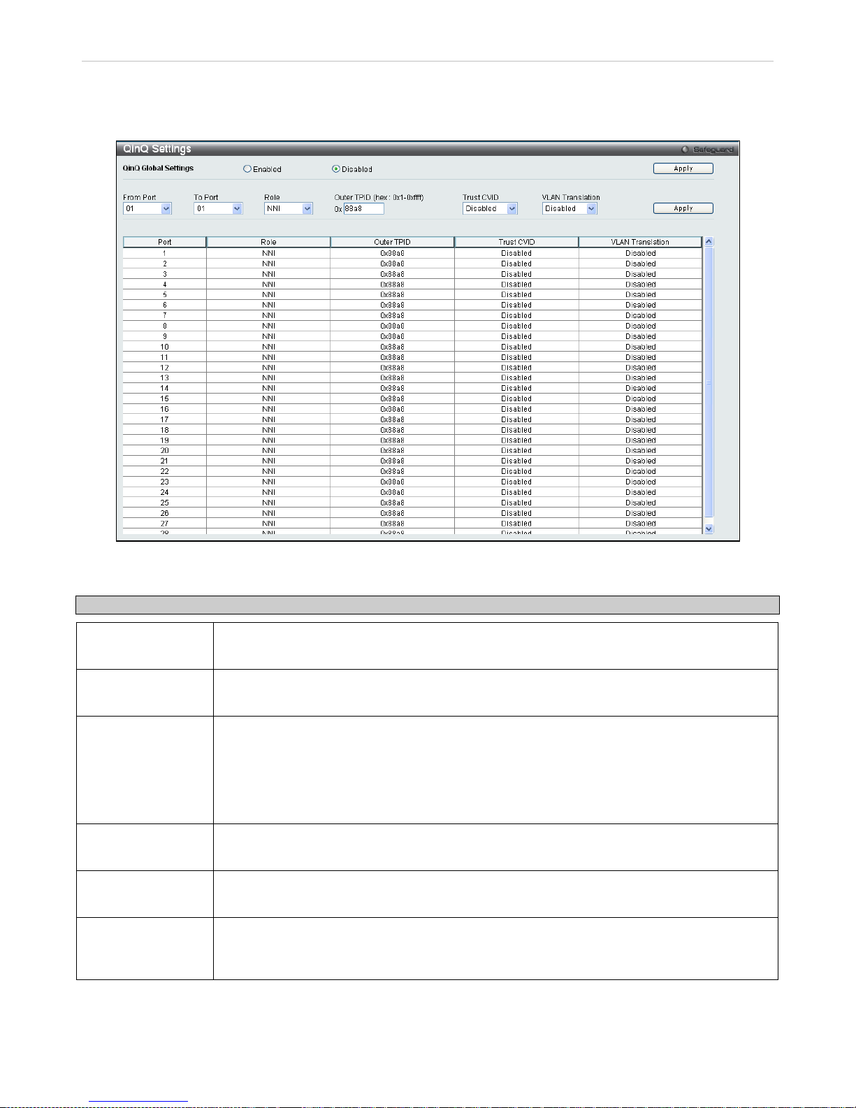
xStack® DES-3200 Series Layer 2 Ethernet Managed Switch WEB UI Reference Guide
71
Q-in-Q Settings
To view this window, click L2 Features > Q-in-Q > Q-in-Q Settings:
Figure 3 - 11. Q-in-Q Settings window
The following fields can be set:
Parameter Description
Q-in-Q Global
Settings
Click the radio button to enable or disable the Q-in-Q Global Settings.
From Port/To Port
A consecutive group of por ts that are part of the VLAN c onfiguration s tarting with the se lected
port.
Role
The user can choose between UNI or NNI role.
UNI – To select a user-network interface which specifies that communication between the
specified user and a specified network will occur.
NNI – To select a network-to-network interface specifies that communication between two
specified networks will occur.
Outer TPID (hex:
0x1 -0xffff)
The Outer TPID is used for learning and s witching packets. The Outer TPID constructs and
inserts the outer tag into the packet based on the VLAN ID and Inner Priority.
Trust CVID Enable or disable the Trus t Customer VLAN ID (CVID ). If the state is Enabled, u se the CVID
from the customer’s packet as the VLAN ID of the SPVLAN tag. The default is Disabled.
VLAN Translation
Enable or disable VLAN T ranslation. T his tr anslates t he VLAN IDs carr ied in th e dat a packets
received from private netw orks into those used in the Service Prov ider’s network . The default
is Disabled. Note: To use this function, Trust CVID must also be enabled.
Click Apply to implement changes.
Page 73
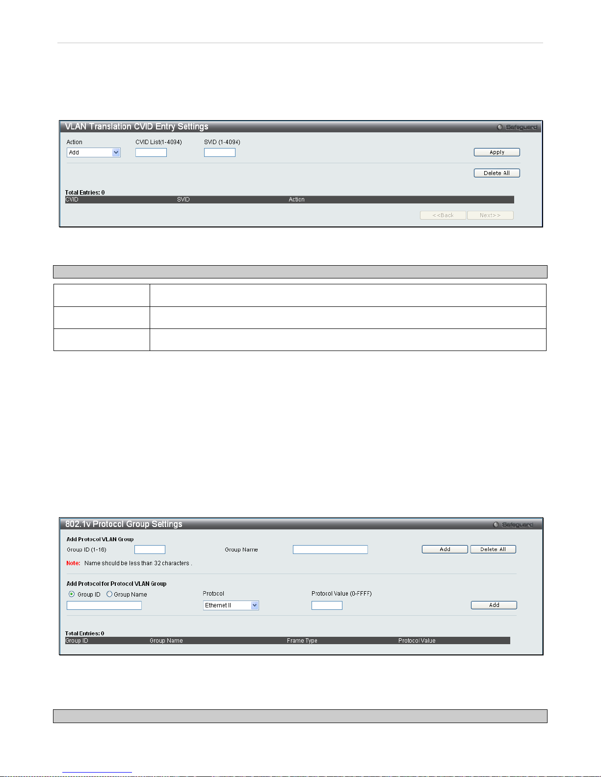
xStack® DES-3200 Series Layer 2 Ethernet Managed Switch WEB UI Reference Guide
72
VLAN Translation Settings
VLAN translation tra nslates the VLAN ID carried in the data pac kets it r eceives f rom private net works into those us ed
in the Service Providers network.
To view this window click L2 Features > Q-in-Q > VLAN Translation CVID Entry Settings:
Figure 3 - 12. VLAN Translation Settings window
The following fields can be set:
Parameter Description
Action Specify to Add or Replace Service Provider VLAN ID (SVID) packets.
CVID (1-4094)
The customer VLAN ID List to which the tagged packets will be added.
SVID(1-4094)
This configures the VLAN to join the Service Providers VLAN as a tagged member.
Click Apply to make a new entry and Delete All to remove a VLAN Translation entry.
802.1v Protocol VLAN
The window allows the user to c reate Protocol VLAN groups and add protoc ols to that group. The 802.1v Protocol
VLAN Group Settings sup ports m ultiple VLANs for each protoco l and allows th e user to configur e the untagged por ts
of different protocols on the same physical port. F or example it allows the us er to configure an 802.1Q a nd 802.1v
untagged port on the same physical port. The lower half of the window displays any previously created groups.
802.1v Protocol Group Settings
To view this window, click L2 Features > 802.1v Protocol VLAN > 802.1v Protocol Group Settings:
Figure 3 - 13. 802.1v Protocol Group Settings window
The following fields can be set:
Parameter Description
Page 74

xStack® DES-3200 Series Layer 2 Ethernet Managed Switch WEB UI Reference Guide
73
Group ID (1-16) Select an ID number for the group, between 1 and 16.
Group Name
This is used to identify the new Prot ocol V LA N gr oup. Type an alphanum er ic s tr ing of up to 32
characters.
Protocol
This function maps pac kets to protocol-d efined VLANs by examining the type oc tet within the
packet header to dis cover the t ype of protoco l associa ted with it. Use the dro p-down m enu to
toggle between Ethernet II and IEEE802.3 SNAP.
Protocol Value
(0-FFFF)
Enter a value for the Group.
Click Add to make a new entry and Delete All to remove an entry.
Page 75
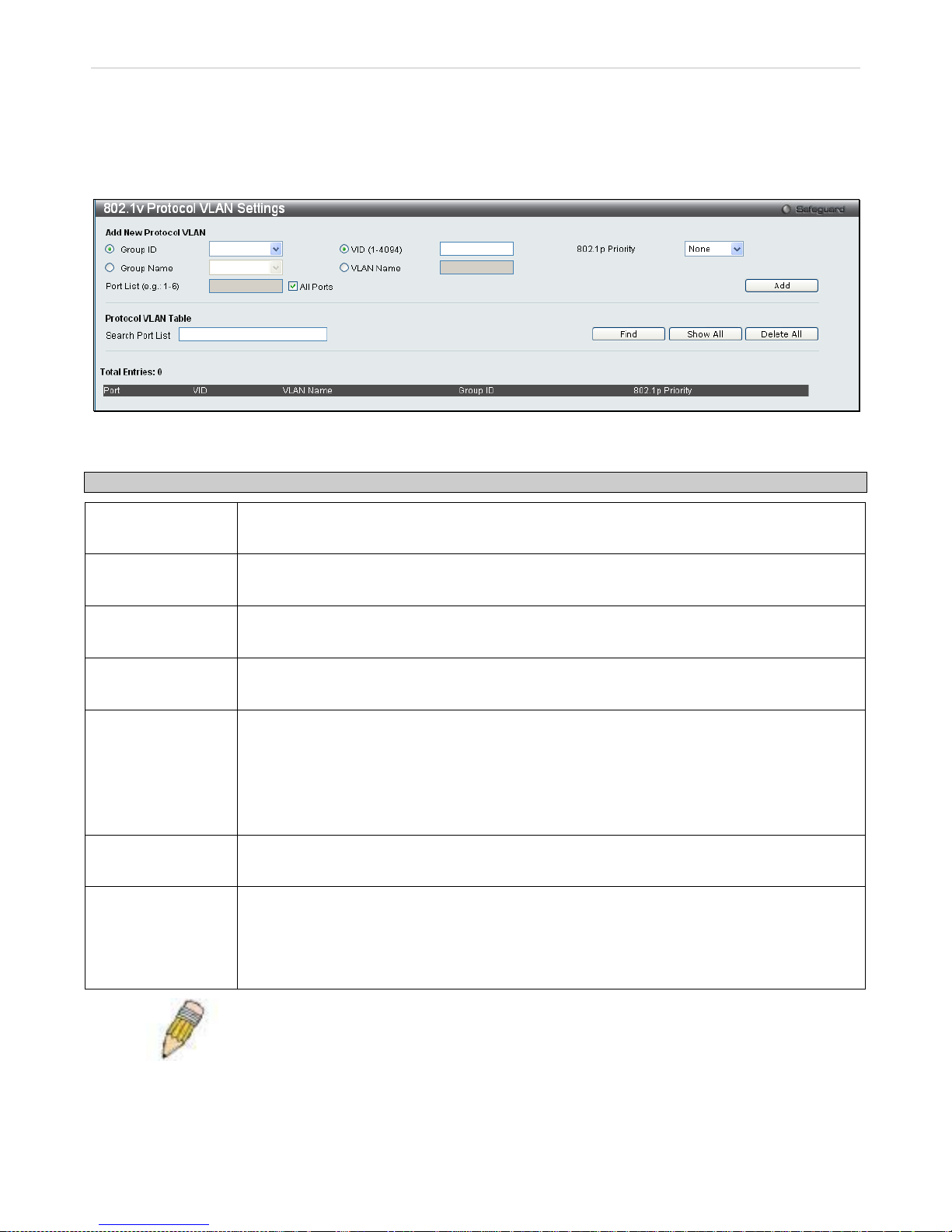
xStack® DES-3200 Series Layer 2 Ethernet Managed Switch WEB UI Reference Guide
74
802.1v Protocol VLAN Settings
The window all o ws the us e r to c onf igur e Prot oc ol VL A N s ettin gs. The lower half of the w in do w disp lays any previousl y
created settings.
To view this window, click L2 Features > 802.1v Protocol VLAN > 802.1v Protocol VLAN Settings:
Figure 3 - 14. 802.1v Protocol VLAN Settings window
The following fields can be set:
Parameter Description
Group ID
Click the corres ponding r ad io butto n to s elect a pre viousl y configur ed Gr oup ID f rom the dr opdown menu.
Group Name
Click the correspond ing radio button to selec t a previously configur ed Group Name from the
drop-down menu.
VID (1-4094)
Click the radio button t o enter the VID. This is the VLAN ID that, a long with the VL AN Name,
identifies the VLAN the user wishes to create.
VLAN Name
Click the radio button to enter a VLAN Name. This is the VL AN Name that, along with the
VLAN ID, identifies the VLAN the user wishes to create.
802.1p Priority
This parameter is spec ified to re-write the 802.1p def ault priority prev iously set in the Switch,
which is used to determ ine the CoS queue to whic h packets are for warded to. Once this fiel d
is specified, pack ets accepted by the S witch that m atch this priority are f orwarded to the CoS
queue specified previously by the user.
For more information on prior ity queues, CoS queues and m apping for 802.1p, see the QoS
section of this manual.
Port List (e.g.: 1-6)
Select the specified ports you wish to co nfigure by entering the port number in this f ield, or tick
the Select All Ports box.
Search Port List
This function allows the user to search all previously configured port list settings and display
them on the lower half of the table. To search for a port list enter the port number you wish to
view and click Find. To display all previously configured port lists on the bottom half of the
window click the Show All button, to clear all previously configured lists click the Delete All
button.
NOTE: For the current release of the DES-3200 , users cannot specify a range o f ports
for 802.1v. The current release only allows users to specify all ports.
Page 76
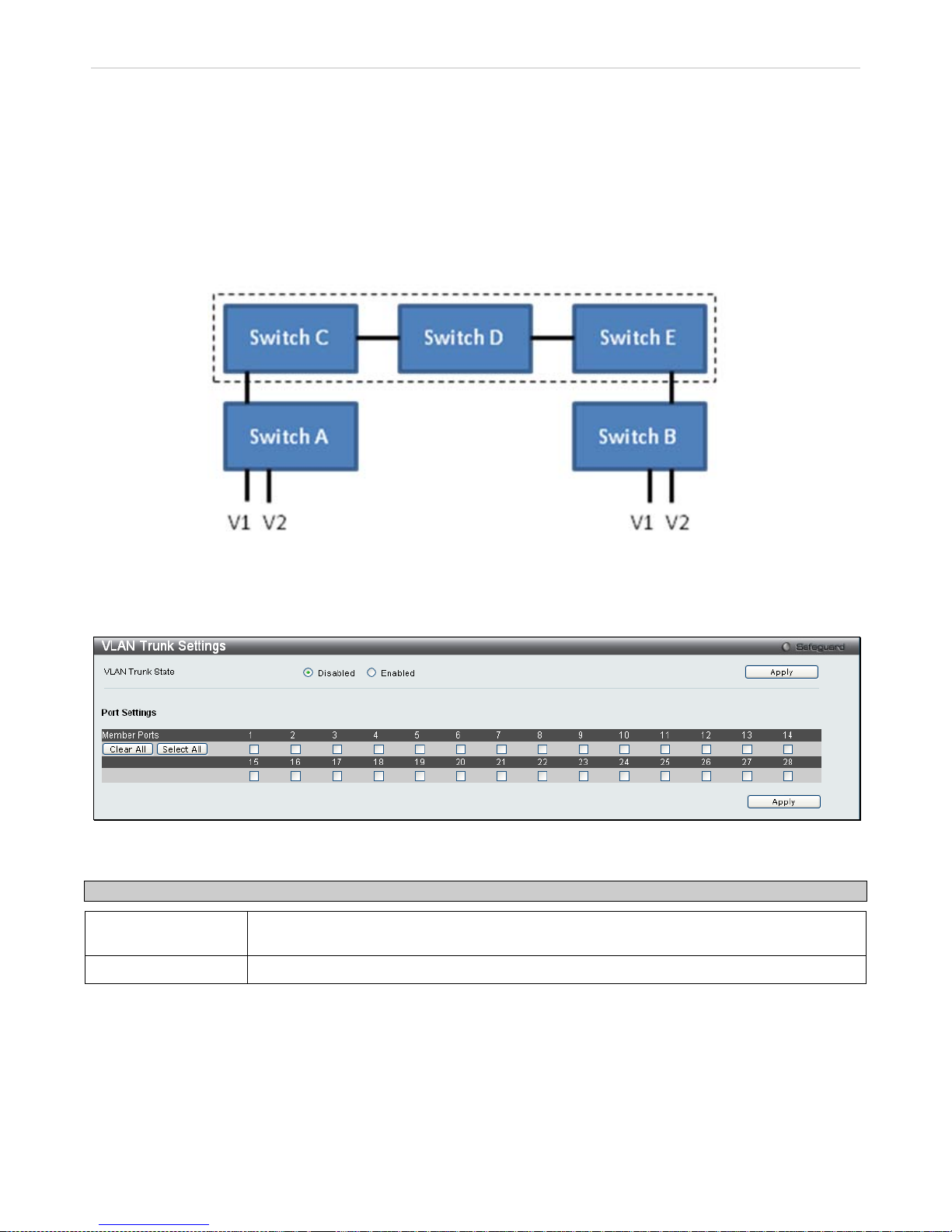
xStack® DES-3200 Series Layer 2 Ethernet Managed Switch WEB UI Reference Guide
75
VLAN Trunk Settings
Enable VLAN on a port to allow fram es belonging to unk nown VLAN gr oups to pass thro ugh th at por t. Thi s is us eful if
you want to set up VLAN groups on en d devices without havi ng to configure the sam e VLAN groups on interm ediary
devices.
Refer to the followin g f igure for an illustr ate d ex ample. Suppose you want to c r eat e V LAN gr o ups 1 and 2 (V1 and V2)
on devices A and B. Without a VLAN Trunk, you must first configure VLAN groups 1 and 2 on all intermediary
switches C, D and E; otherwise the y will drop frames with unknown VLAN group tags. Ho wever, with VLAN Trunk
enabled on a port(s) in each in termediar y switch, you onl y need to crea te VLAN groups in the end devices ( A and B).
C, D and E automatically allow frames with VLAN group tags 1 and 2 (VLAN groups that are unknown to those
switches) to pass through their VLAN trunking port(s).
Users can combine a number of VLAN ports together to c reate VLAN trunks. T o create VLAN Trunk Port settings on
the Switch, select the ports to be conf igured, change the VLAN Trunk Globa l State to Enabled, and click Apply, the
new settings will appear in the VLAN Trunk Settings table in the lower part of the window.
To view the following window, click L2 Features > VLAN Trunk Settings:
Figure 3 - 15. VLAN Trunk Settings window
The user-changeable parameters are as follows:
Parameter Description
VLAN Trunk Global
State
Enable or disable the VLAN trunking global state.
Ports
The ports to be configured.
Page 77
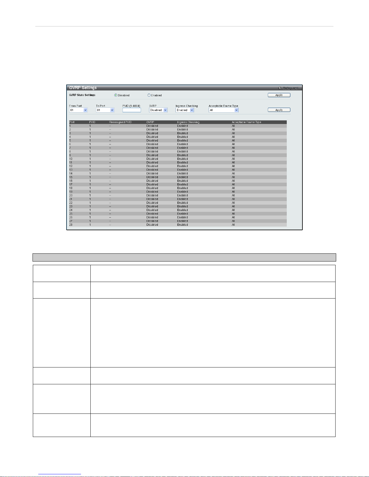
xStack® DES-3200 Series Layer 2 Ethernet Managed Switch WEB UI Reference Guide
76
GVRP Settings
This windo w allows the user to determ ine whether th e Switch will s hare its V LAN configura tion infor mation with o ther
GARP VLAN Registrat io n Pr otocol (GVRP) enabled switches. In ad dit ion, I ngress Checking ca n b e us ed to limit traffic
by filtering incoming pac kets whose PVID do not match the P VID of the port. Re sults can be seen i n the table und er
the configuration settings, as seen below.
To view this window, click L2 Features > GVRP Settings:
Figure 3 - 16. GVRP Settings window
The following fields can be set:
Parameter Description
GVRP State
Settings
Click the radio buttons to enable or disable the GVRP global state settings.
From Port/To Port
These two fields allow you to s pecify the range of port s that will be included in th e Port-based
VLAN that you are creating using the 802.1Q Por t Settings window.
PVID (1-4094)
Enter a PVID assignment for each port, which may be manually assigned to a VLAN when
created in the 802.1Q Port Settings table. The Switch's default is to assign all ports to the
default VLAN with a VID of 1. T he PVID is used b y the port to tag out going, untag ged pack ets ,
and to make filtering dec isions about incoming pack ets. If the port is specified to ac cept only
tagged frames - as tagging, and an unt agged packet is f orwarded to the port for trans mission,
the port will add an 802.1 Q tag using the PVID to write the VID in the tag . When the packet
arrives at its destination, the receiving device will use the PVID to make VLAN forwarding
decisions. If the port rece ives a packet, and Ingress f iltering is enabled, the port wi ll compare
the VID of the incom ing pa cket to its PVID. If the t wo ar e un eq ual , th e p or t wil l dr op t he pac ket.
If the two are equal, the port will receive the packet.
GVRP
The Group VLAN Registration Protocol (GVRP) enables the port to dynamically become a
member of a VLAN. GVRP is Disabled by default.
Ingress Checking This field can be tog gl ed using the space bar b et ween Enabled and Disabled. Enabled enables
the port to com pare the VID tag of a n incoming pac ket with the PVID number a ssigned to the
port. If the two are dif ferent, the port filters (drops) the p acket. Disabled disa bles ingress filtering. Ingress Checking is Enabled by default .
Acceptable Frame
Type
This field denotes the t ype of frame that will be accepted by the port. T he user may choose
between Tagged On ly, which means only VLAN t agg e d frames will be accept ed, and All, which
mean both tagged and untagged frames will be accepted. All is enabled by default.
Click Apply to implement changes made.
Page 78
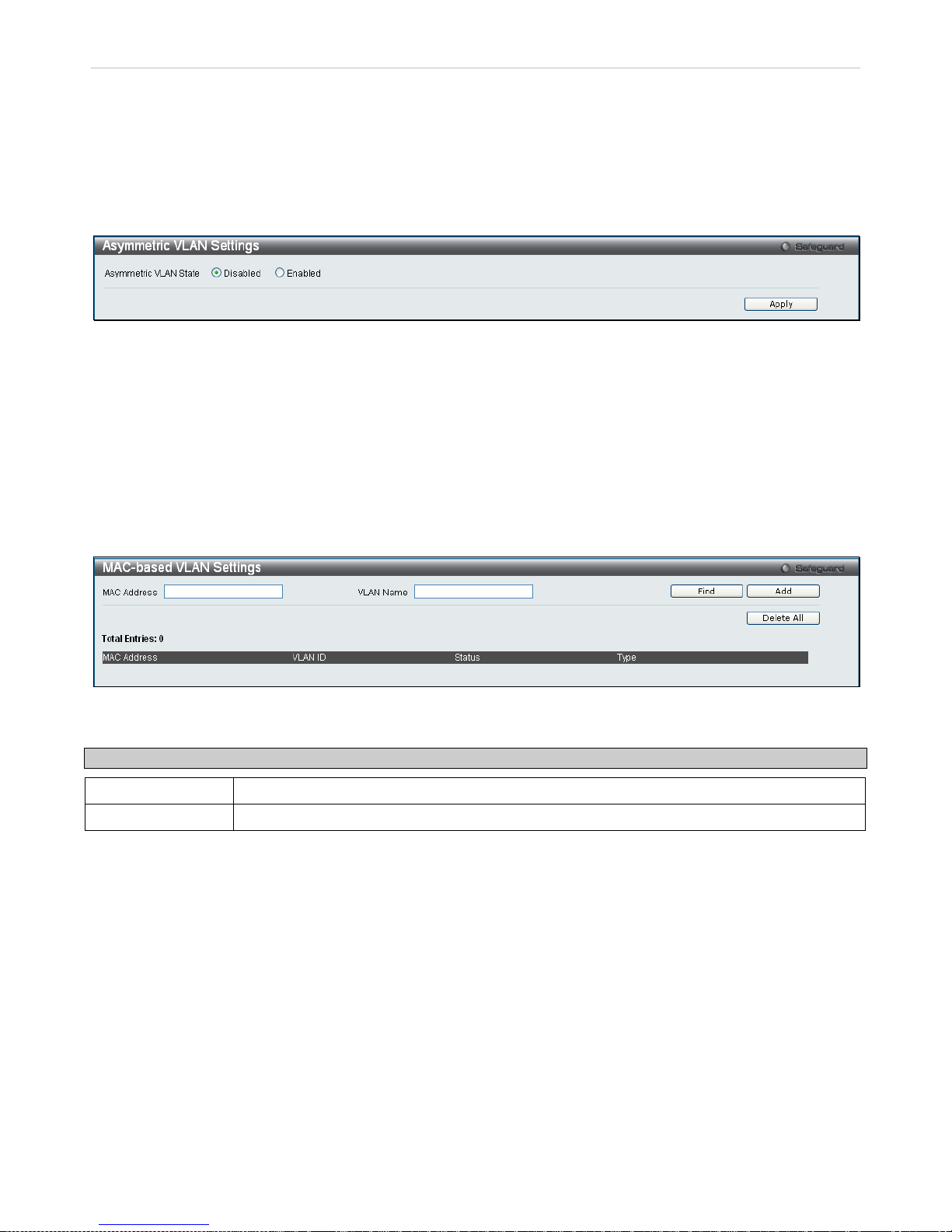
xStack® DES-3200 Series Layer 2 Ethernet Managed Switch WEB UI Reference Guide
77
Asymmetric VLAN Settings
Under normal circumstances, a pair of devices communicating in a VLAN environment will both send and receive
using the same VLAN; how ever, there are some circum stances in which it is convenient t o make use of two distinct
VLANs, one used for A to t ransmit to B and the other used for B to transmit to A in these cases Asymm etric VLANs
are needed. An exam ple of when this type of c onf igura tion might be required wou l d be if the c l ient was o n a d istinc t I P
subnet, or if there was some confidentiality-related need to segregate traffic between the clients.
To view this window, click L2 Features > Asymmetric VLAN Settings:
Figure 3 - 17. Asymmetric VLAN Settings window
Click Apply to implement changes.
MAC-based VL AN Settings
This window is used to create MAC-based VLAN entries on the switch. A MAC Address can be mapped to any
existing static VLAN and multiple MAC addresses can be mapped to the same VLAN. When a static MAC-based
VLAN entr y is created f or a user, the traff ic from this user is able to be serviced u nder the specif ied VLAN. Therefore
each entry specifies a relationship of a source MAC address with a VLAN.
To view this window, click L2 Features > MAC-based VLAN Settings:
Figure 3 - 18. MAC-based VLAN Settings window
The following fields can be set
Parameter Description
MAC Address
Specify the MAC address to be mapped.
VLAN Name
Enter the VLAN name of a previously configured VLAN.
Click Find, Add or Delete All for changes to take effect.
Page 79
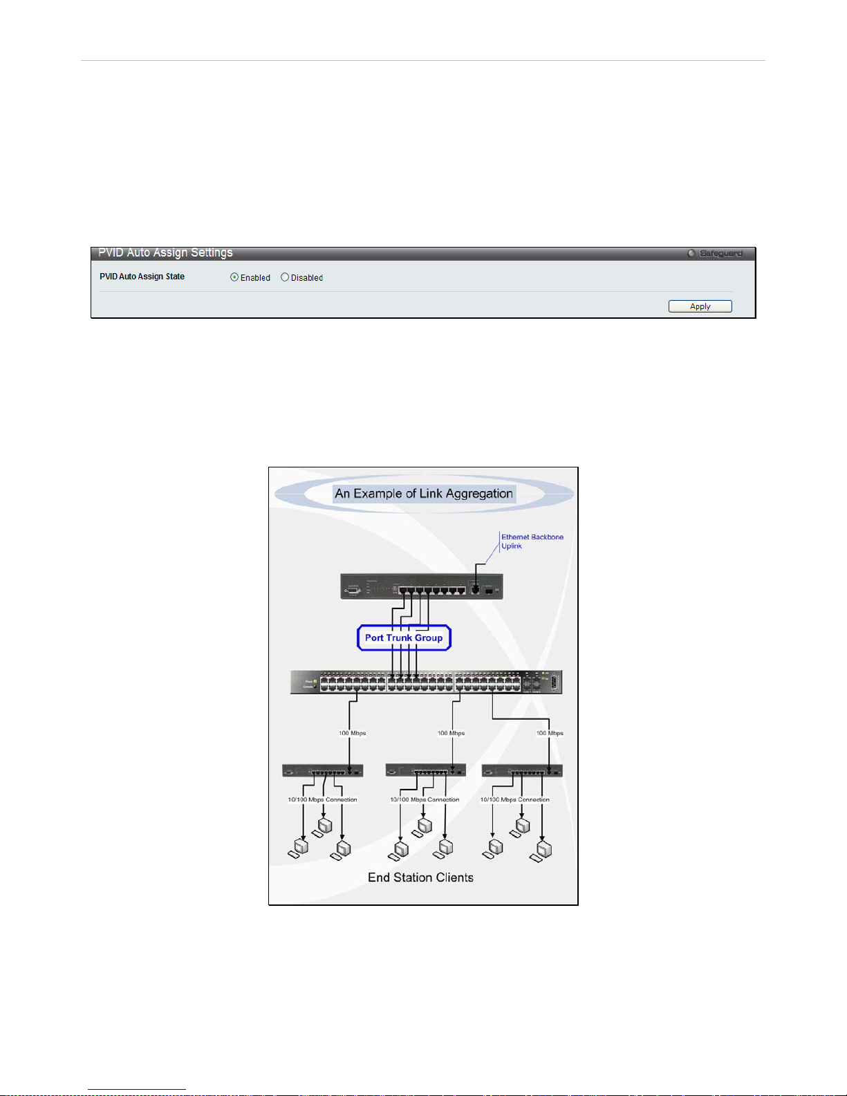
xStack® DES-3200 Series Layer 2 Ethernet Managed Switch WEB UI Reference Guide
78
PVID Auto Assign Settings
This enables or disables PVID Auto Assign on the Switch. PVID is the VLAN that the switch will use for forwarding and
filtering purposes. If PVID Auto-Assign is Enabled, PVID will be possibly changed b y previously set PVID or VLAN
configurations. When a user configures a port to VLAN X’s untagge d membership, this port’s PVID will be updated
with VLAN X. In the f orm of a VLAN list comm and, PVID is updat ed with the las t item on the VLAN list. W hen a user
removes a port from the untag ged membership of the PVI D’s VLAN, the port’s PVID will be assigned to a def ault
VLAN. When PVID Auto Assign is Disabled, PVID can only be changed by PVID configuration (user changes
explicitly). The VLAN configuration will not automatically change the PVID. The default setting is Enabled.
To view this window, click L2 Features > PVID Auto Assign Settings:
Figure 3 - 19. PVID Auto Assign Settings window
Port Trunking
Understanding Port Trunk Gr oups
Port trunk groups are us ed to c om bine a num ber of ports together to m ake a sing le high-bandwidth data p ipeline. T he
Switch supports up to fourteen port trunk groups with two to eight ports in each group.
Figure 3 - 20 Example of Port Trunk Group
The Switch treats all ports in a trunk group as a single port. Data trans mitted to a specific host ( destination address)
will always be transm itted over the same port in a trunk group. This allo ws packets in a data str eam to arrive in the
same order they were sent.
Page 80
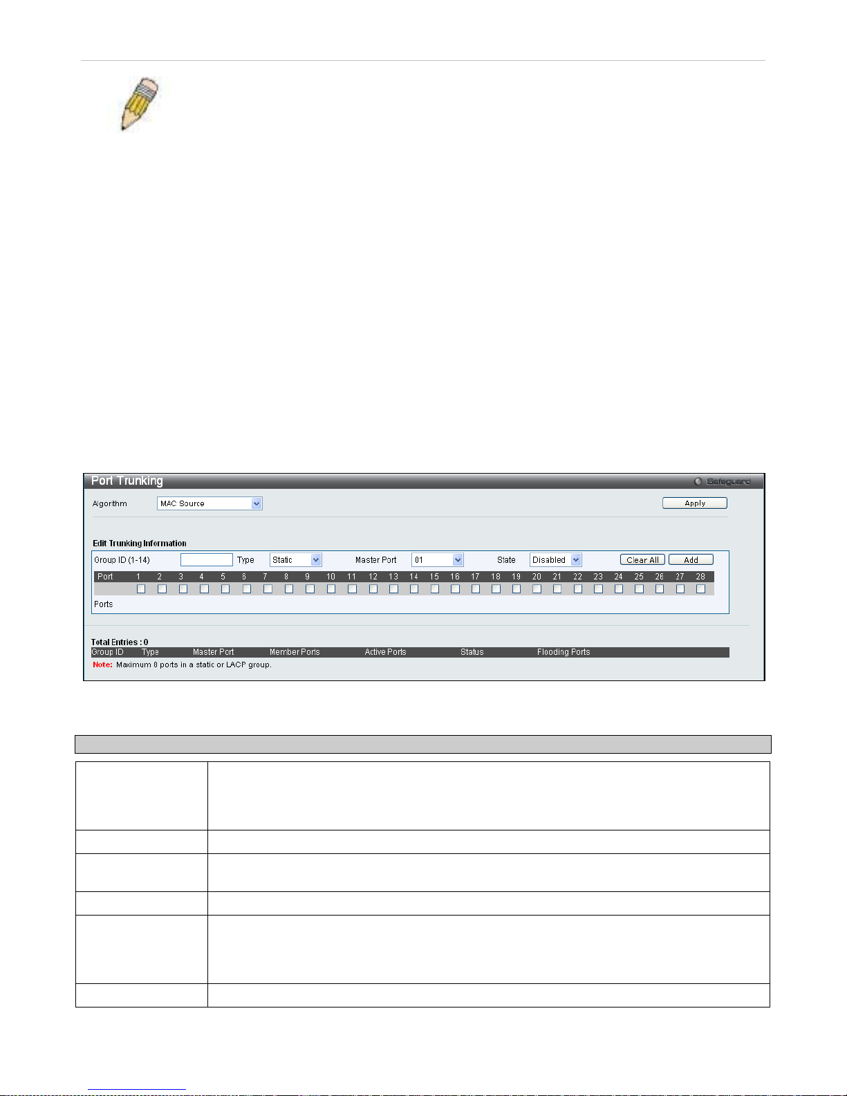
xStack® DES-3200 Series Layer 2 Ethernet Managed Switch WEB UI Reference Guide
79
NOTE: If any ports within the trunk group become disconnected, packets intended for the
disconnected port wil l be load shared among the oth er unlinked ports of the link aggregation
group.
Link aggregation all o ws s e vera l p orts to be gr o upe d t oget her a nd to ac t as a s i n gle l ink. This gives a ba nd widt h th at is
a multiple of a single link's bandwidth.
Link aggregation is m ost comm only used to li nk a bandwidt h intensi ve net work device or dev ices, s uch as a s erver, to
the backbone of a network.
The Switch allows the crea tion of up to fourteen link aggr egation groups, each group cons isting of two to eight link s
(ports). All of the por ts in t he grou p m ust be m em bers of the sam e VL AN, and th eir ST P stat us, st atic m ultica st, tr aff ic
control; traffic segm entation and 802.1p default priorit y configurations must be identical. Port loc king, port mirroring
and 802.1X must not be en abled on the tru nk group. F urther , the aggr egated link s m us t all be of the sam e speed and
should be configured as full duplex.
The Master Port of the group is to be configured by the user, and all configuration options, including the VLAN
configuration that can be applied to the Master Port, are applied to the entire link aggregation group.
Load balancing is autom atic all y appl ied t o the p or ts in the ag gr ega ted gr oup, and a link failure withi n the grou p c aus es
the network traffic to be directed to the remaining links in the group.
The Spanning Tree Protocol will treat a link aggregat ion group as a single link , on the switch level. On the port level,
the STP will use the port par ameters of the Master Port in the calculat ion of port cost and in de termining the state of
the link aggregation group. If two red undant l ink aggre gation grou ps are c onfigur ed on the Switch, ST P will block one
entire group; in the same way STP will block a single port that has a redundant link.
To view this window, click L2 Features > Port Trunking:
Figure 3 - 21. Port Trunking window
The following fields can be set
Parameter Description
Algorithm
The algorithm that the Swit ch uses to balance the loa d across the ports that m ake up the port
trunk group is def ined by this definit ion. Choose MAC Sourc e, MAC Destination, MAC Source
Dest, IP Source, IP Destination or IP Source Dest ( See the Link Aggregation section of this
manual).
Group ID (1-14) Select an ID number for the group, between 1 and 14.
Type This pull-do wn menu allow s you to s elect between Static and LACP (Link Ag gregation C ontrol
Protocol). LACP allows for the automatic detection of links in a Port Trunking Group.
Master Port
Choose the Master Port for the trunk group using the pull-down menu.
State Trunk groups can be toggled between Enabled and Disabled. This is used to turn a port
trunking group on or off . This is useful for di agnostics, to quick ly isolate a bandwidth intensive
network device or to have an absolute backup aggregati on group that is not under autom atic
control.
Active Ports
Shows the ports that are currently forwarding packets.
Page 81
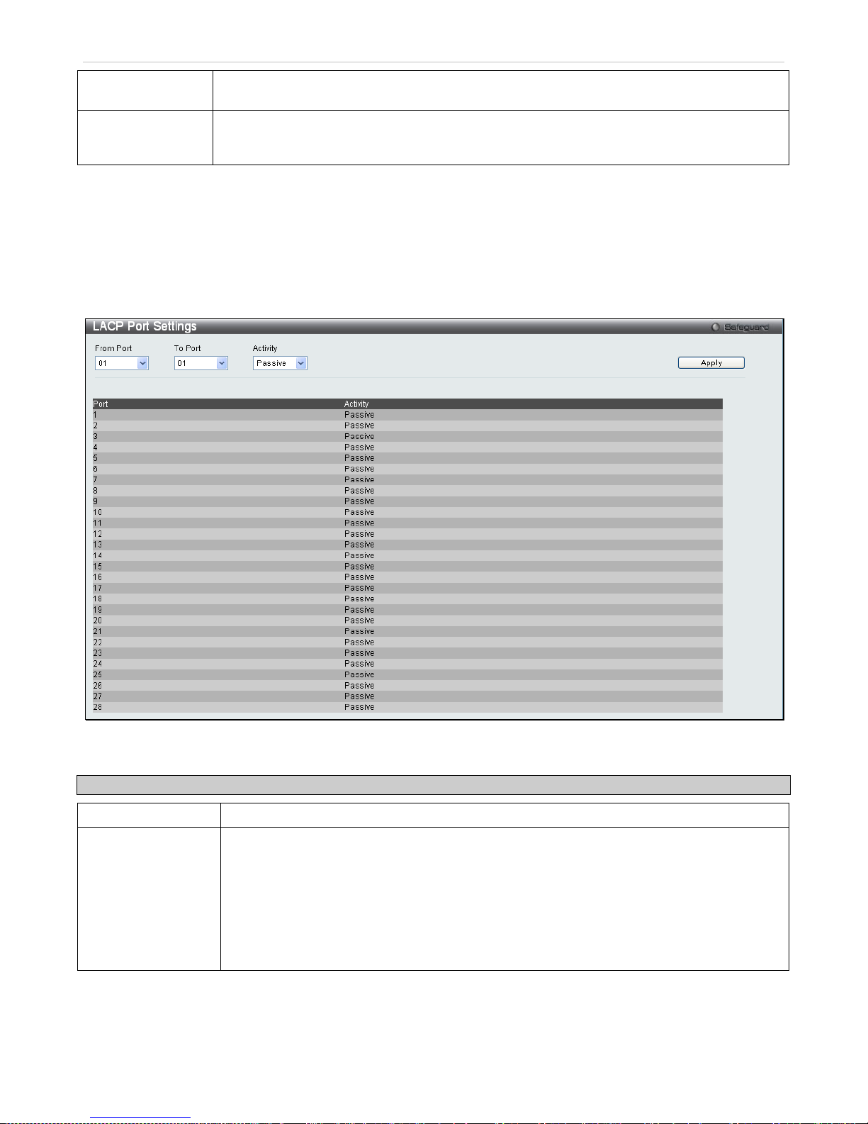
xStack® DES-3200 Series Layer 2 Ethernet Managed Switch WEB UI Reference Guide
80
(Member) Ports
Choose the members of a trunked group. Up to eight ports per group can be assigned to a
group.
Flooding Ports
These ports are designated for flooding broadcast, multicast, and DLF (unicast Destination
Lookup Fail) packets from the CPU in a trunk group. The port is defined by software and
doesn’t actually exist in the hardware.
Click Apply to implement changes made.
LACP Port Settings
This window is used to create port trunking groups on the Switch. The user may set which ports will be active and
passive in processing and sending LACP control frames.
To view this window, click L2 Features > LACP Port Settings:
Figure 3 - 22. LACP Port Settings window
The following fields can be set
Parameter Description
From Port/To Port
A consecutive group of ports may be configured starting with the selected port.
Activity
Active - Active LAC P ports ar e capab le of proces sing and sending LAC P con trol f rames . This
allows LACP compliant devices to negotiate the aggregated link so the group may be
changed dynamicall y as needs require. In ord er to utilize the abil ity to change an aggre gated
port group, that is, to add or s ubtract ports from the group, at least one of the partici pating
devices must designate LACP ports as active. Both devices must support LACP.
Passive - LACP ports that are designated as passive cannot initially send LACP control
frames. In order to allow the linked port group to negoti ate adjustments and make changes
dynamically, one end of the connection must have "active" LACP ports (see above).
Click Apply to implement changes made.
Page 82
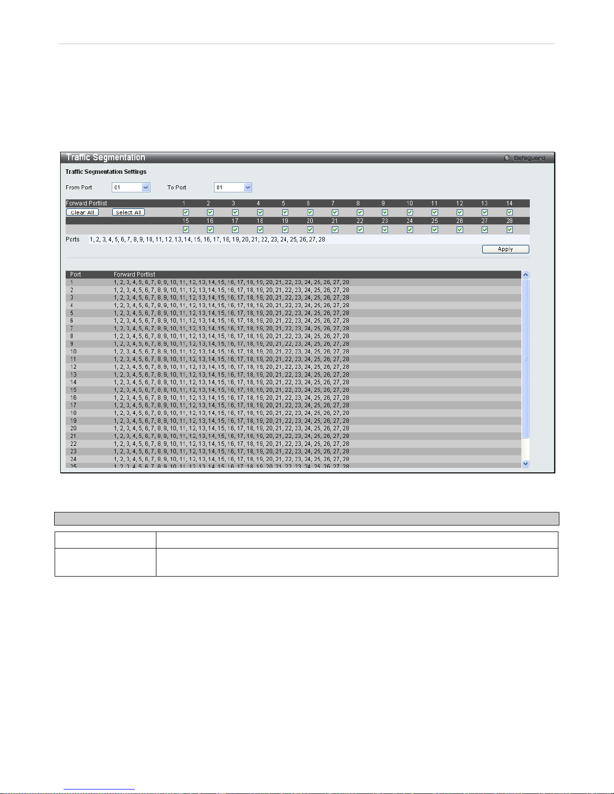
xStack® DES-3200 Series Layer 2 Ethernet Managed Switch WEB UI Reference Guide
81
Traffic Segmentation
Traffic segmentation is use d to limit traffic flow from a single por t to a group of ports on the Switc h. This method of
segmenting the flo w of traffic is sim ilar to using VLAN s to limit traff ic, but is more restr ictive. It provides a method of
directing traffic that does n ot increase the overhead of the S witch CPU. This window allows the user to view which
ports on the Switch are al lowed to f or ward pack ets to other p orts on th e Sw itch. T o conf igure ne w forwardi ng por ts f or
a particular port, select a port from the From Port and To Port drop-down menus and click Apply.
To view this window, click L2 Features > Traffic Segmentation:
Figure 3 - 23. Traffic Segmentation window
The following fields can be set
Parameter Description
From Port/To Port
Check the corresponding boxes for the port(s) to transmit packets.
Forward Portlist
Check the boxes to s elect which of th e ports on the Switch will be able to forwar d packets.
These ports will be allowed to receive packets from the port specified above.
Clicking the Apply b utton will enter t he combination of transmitting port and allowed rec eiving ports into t he Switch's
Current Traffic Segmentation Table.
Page 83
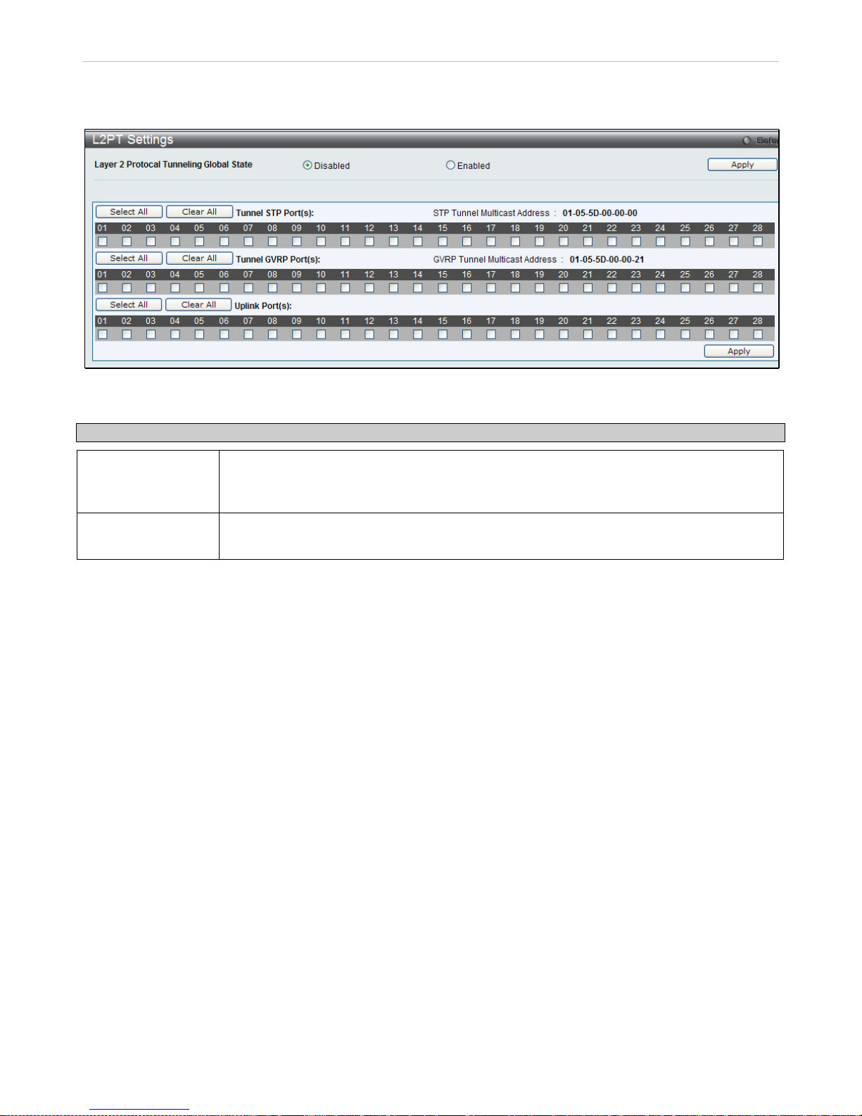
xStack® DES-3200 Series Layer 2 Ethernet Managed Switch WEB UI Reference Guide
82
Layer 2 Protocol Tunneling Settings
To view this window, click L2 Features > L2PT Settings:
Figure 3 - 24. Layer 2 Tunneling Settings window
The fields that can be configured are described below:
Parameter Description
Layer 2 Protocol
Tunneling Global
State:
To enable or disable the Layer 2 Protocol Tunneling state.
Port(s):
The user can select the port numbers that will be included in the Layer 2 Protocol Tunneling
configuration.
Click Apply to implement changes made.
Page 84
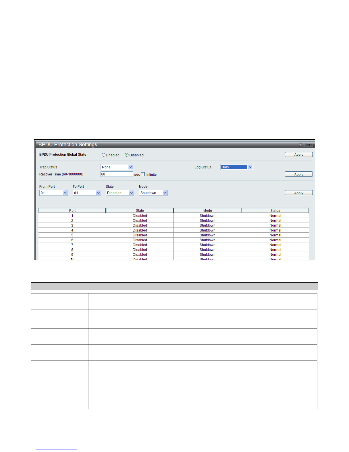
xStack® DES-3200 Series Layer 2 Ethernet Managed Switch WEB UI Reference Guide
83
BPDU Attack Protection Settings
This menu is used to c onfigure the BPDU pro tection function for the p orts on the switch. In generally, there are tw o
states in BPDU prot ection function. One is norm al state, and another is under attack s tate. The under attack state
have three modes: drop, block, and shutdown. A BPDU protection enabled port will enter an under attack state when it
receives one STP BPDU packet. And it will take action based on the configuration. Thus, BPDU protection can only be
enabled on STP-disabled port.
BPDU protection has a hi gher priority than th e Forward BPDU sett ing configured in the ST P Port Settings m enu (L2
Features > Spanning Tree > STP Port Settings). That is, when a p ort configured to t he Forward BPDU ( STP Port
Settings window) and BPDU protection is enabled, then the port will not forward STP BPDU.
BPDU protection also has a higher priority than the L ayer 2 Protocol Tunneling port setting in the determ ination of
BPDU handling. That is, when a port is configured as La yer 2 Protocol Tunnel port for Tunnel STP (L2 F eatures >
L2PT Settings), it will forward STP BPDU. But if the port is BPDU protection en abled, then the por t will not forward
STP BPDU.
To view this window, click L2 Features > BPDU Protection Settings:
Figure 3 - 25. BPDU Protection Settings window
The fields that can be configured are described below:
Parameter Description
BPDU Protection
Global State:
To enable or disable the BPDU Protection Global State to enable BPDU Attack Protection
globally. The default state is Disabled.
Trap State:
To specify the trap state. The default state is none.
Log State:
To specify the log state. The default state is both.
Recover Time:
Specified the BPDU protection Auto-Recovery timer. The default value of the recovery timer is
60. Recover Time can be set between 60 and 1000000 seconds.
From Port – To
Port:
To select a range of ports to use for this configuration.
State:
To enable or disable the mode for a specific port.
Mode:
Specified the BPDU protection mode. The default mode is shutdown.
Drop – Drop all received BPDU packets when the port enters under attack state.
Block – Drop all packets (include BPDU and normal packets) when the port enters under
attack state.
Shutdown – Shut down the port when the port enters under attack state.
Click Apply for the menu being configured to implement changes made.
Page 85
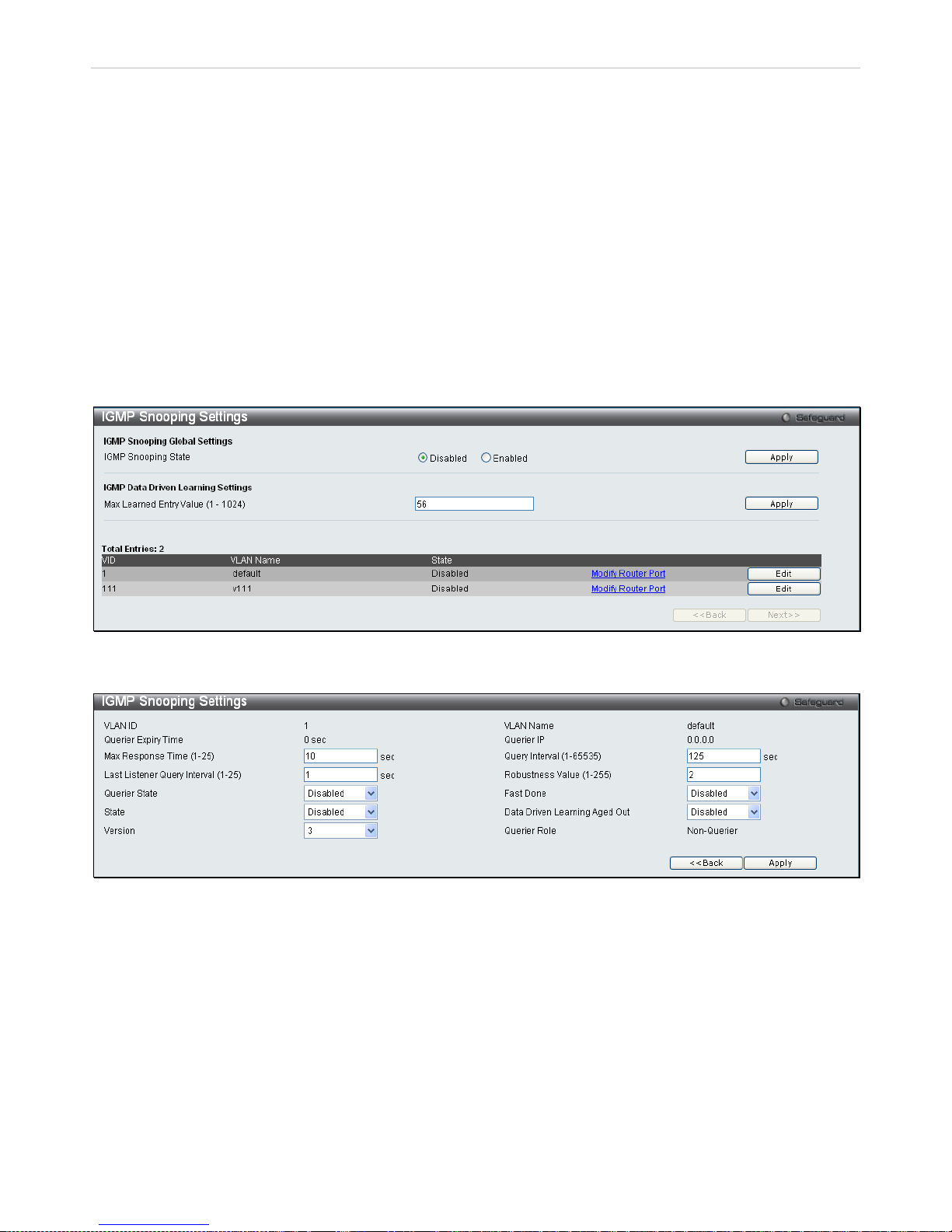
xStack® DES-3200 Series Layer 2 Ethernet Managed Switch WEB UI Reference Guide
84
IGMP Snoopin g
Internet Group Manag em ent Protoc ol (IG MP) s noop ing a llows t he Switc h to r eco gnize IGM P quer ies and re ports s ent
between network stations or devices and an IGMP host. When enab led for IGMP snooping, the Switch can add or
remove a port to a specific device based on IGMP messages passing through the Switch.
In order to use IG MP Snooping, it must f irst be enabled for the entir e Switch. Then, fine-tu ne the settings for each
VLAN using the IGM P Snooping windows in the L2 Features folder. When en abled for IGMP s nooping, the Switc h
can open or close a port to a spec ific multicas t group mem ber based on IGMP mess ages sent from the device to the
IGMP host or vice versa. T he Switch monitors IGM P messages and disc ontinues forwarding m ulticast packets when
there are no longer hosts requesting that they continue.
IGMP Snooping Settings
Use this window to en ab le or disa bl e IG M P s n oop in g on t he S witc h. T he IGMP Snooping Stat e under IGMP Snoop ing
Global Settings can be enabl ed or disabled and a Max Learn ing Entry Value bet ween 1 and 1024 can be entered in
the field under IGMP Data Driven Learning Settings. Click Apply to modify the settings.
To view this window, click L2 Features > IGMP Snooping > IGMP Snooping Settings:
Figure 3 - 26. IGMP Snooping Settings window
Clicking the Edit button will open this window:
Figure 3 - 27. IGMP Snooping Settings (Edit) window
Page 86
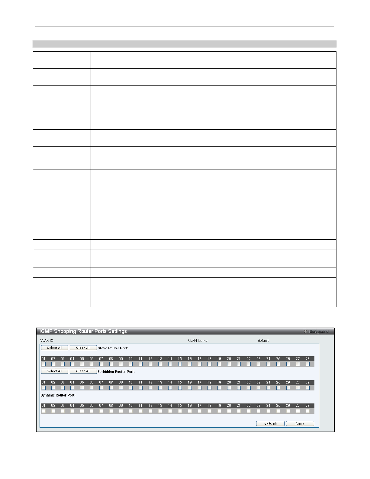
xStack® DES-3200 Series Layer 2 Ethernet Managed Switch WEB UI Reference Guide
85
The following fields can be set.
Parameter Description
VLAN ID
This is the VLAN ID th at, along with the VLAN Nam e, identifies the VLAN f or which the user
wishes to modify the IGMP Snooping Settings.
VLAN Name
This is the VLAN Nam e that, along with the VLAN ID , identifies the VLAN f or which the user
wishes to modify the IGMP Snooping Settings.
Querier Expiry
Time
Displays the querier expiry time.
Querier IP
The IP address of the device which acts as the IGMP querier for the network.
Max Response
Time (1-25)
This determines the max imum amount of time in seconds to wait for reports from members.
The Max Response Time field allows an entry between 1 and 25 (seconds). The default is 10.
Query Interval
(1-65535)
The Query Interval field is used to set the time (in seconds) between transmitting IGMP
queries. Entries between 1 and 65535 seconds are allowed. The default is 125.
Last Listener
Query Interval
(1-25)
This field specifies the maximum amount of time between group-specific query messages,
including those sent in response to leave group messages. The default is 1.
Robustness Value
(1-255)
Adjust this variable acc ording to expec ted packet loss . If pack et loss on the VLA N is expected
to be high, the Robustnes s Variable should be increased to accomm odate increased packet
loss. This entry field allows an entry of 1 to 255. The default is 2.
Querier State Choose Enabled to enable transmitting IGMP query packets or Disabled
to disable the
transmitting of IGMP query packets. The default is Disabled.
Fast Done
This parameter allows the us er to enable the Fast Leave function. Enabled, this function will
allow members of a multicast group to leave the group
immediately (without the
implementation of the Last Member Query Timer) when an IGMP Leave Report Packet is
received by the Switch. The default is Disabled.
State Select Enabled to implement IGMP Snooping. This field is Disabled by default.
Data Driven
Learning Aged Out
Allows users to enable or disable aged out of IGMP Snooping data driven learning for the
specified VLAN.
Version Allows the user to configure the IGMP version used on the Switch. The default value is 3.
Querier Role
This read-only field describes the behavior of the Switch for sending query packets. Querier will
denote that the Switch is s ending out IGMP query packets. Non-Querier will d enote that the
Switch is not sending out IGMP query packets. This field will only read Querier when the
Querier State and the State fields have been Enabled.
To modify the IGMP Sno oping Router Port Settings, click on the Modify Router Port hyperlink, which will show the
following window for the user to configure:
Figure 3 - 28. IGMP Snooping Router Ports Settings window
Page 87
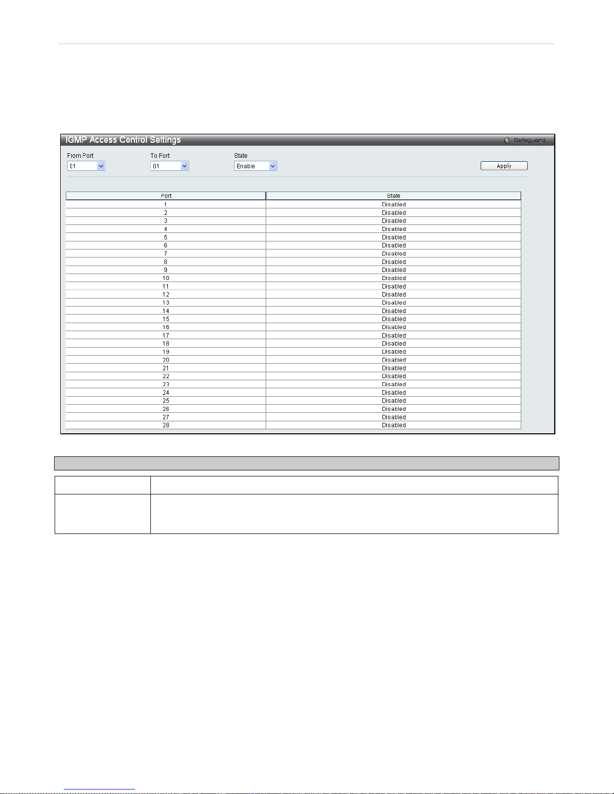
xStack® DES-3200 Series Layer 2 Ethernet Managed Switch WEB UI Reference Guide
86
Select the desired member ports and click Apply. Click <<Back to go back to the IGMP Snooping Settings window.
IGMP Access Control Settings
This window is used to configure IGMP Access Control settings on the Switch.
To view this window, click L2 Features > IGMP Snooping > IGMP Access Control Settings:
Figure 3 - 29. IGMP Access Control Settings window
Parameter Description
From Port/To Port
Select a range of ports.
State
Enable or disable the IG MP Access Control. W hen Enable is se lected and th e Switch r eceives
an IGMP Join reques t, the Switch will s end th e acces s reques t to t he R ADIUS server t o d o the
authentication.
Click Apply to implement changes made.
Page 88
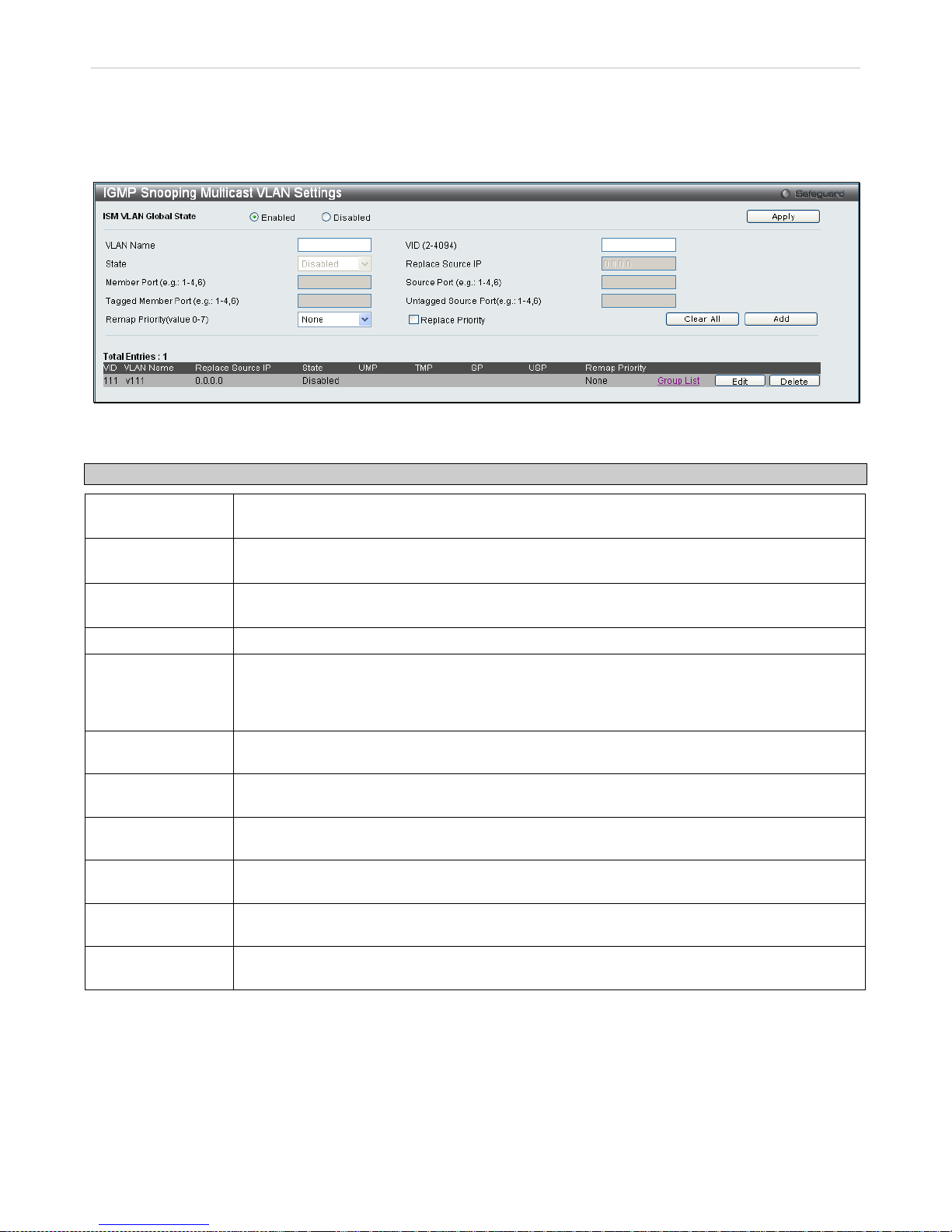
xStack® DES-3200 Series Layer 2 Ethernet Managed Switch WEB UI Reference Guide
87
IGMP Snooping Multicast VLAN Settings
This window is used to configure the IGMP Snooping Multicast VLAN settings on the Switch.
To view this window, click L2 Features > IGMP Snooping > IGMP Snooping Multicast VLAN Settings:
Figure 3 - 30. IGMP Snooping Multicast VLAN Settings window
The following fields can be set
Parameter Description
ISM VLAN Global
State
Click the Enabled or Disabled radio button to enable or disable multicast VLAN.
VLAN Name
This is the VLAN Name that, along wit h the VLAN ID, ident ifies the VLAN the u ser wishes to
add or modify the IGMP Snooping Settings for.
VID (2-4094)
This is the VLAN ID that, along with the VLAN Name, identifies t he VLAN the user wishes to
add or modify the IGMP Snooping Settings for.
State Enable or disable multicast VLANs for the chosen VLAN.
Replace Source IP
With the IGMP snooping f unc tion, th e IGM P repor t pack et sent b y the hos t wi ll be f orward ed to
the source port. Before forwarding of the packet, the source IP address in the join packet
needs to be replaced by thi s IP addres s. If none is s pecified, the sour ce IP ad dress wil l not be
replaced.
Member Port (e.g.:
1-4, 6)
A range of member ports to add to the multicast VLAN. They will become the untagged
member ports of the ISM VLAN.
Source Port (e.g.:
1-4, 6)
Select the source Port for the multicast VLAN.
Tagged Member
Port (e.g.: 1-4, 6)
Specifies the ports that will be tagged as members of the multicast VLAN.
Untagged Source
Port (e.g.: 1-4, 6)
A range of untagged sourc e ports to add to the multicast VLAN . The reassigned PVID of the
untagged source port will be automatically changed to the multicast VLAN.
Remap Priority
(Value 0-7)
The remap priority is ass ociated with t he data traff ic to be forwarde d on the m ulticast VLAN. If
None is selected, the packet’s original priority will be used. The default setting is None.
Replace Priority
Tick this option so th at the pack et’s priorit y will be c hanged bas ed on t he rem ap priorit y by the
Switch. This option takes effect only when remap priority is set.
To edit an entry, click the corresponding Edit button. To delete an entry, click the corresponding Delete button.
Page 89
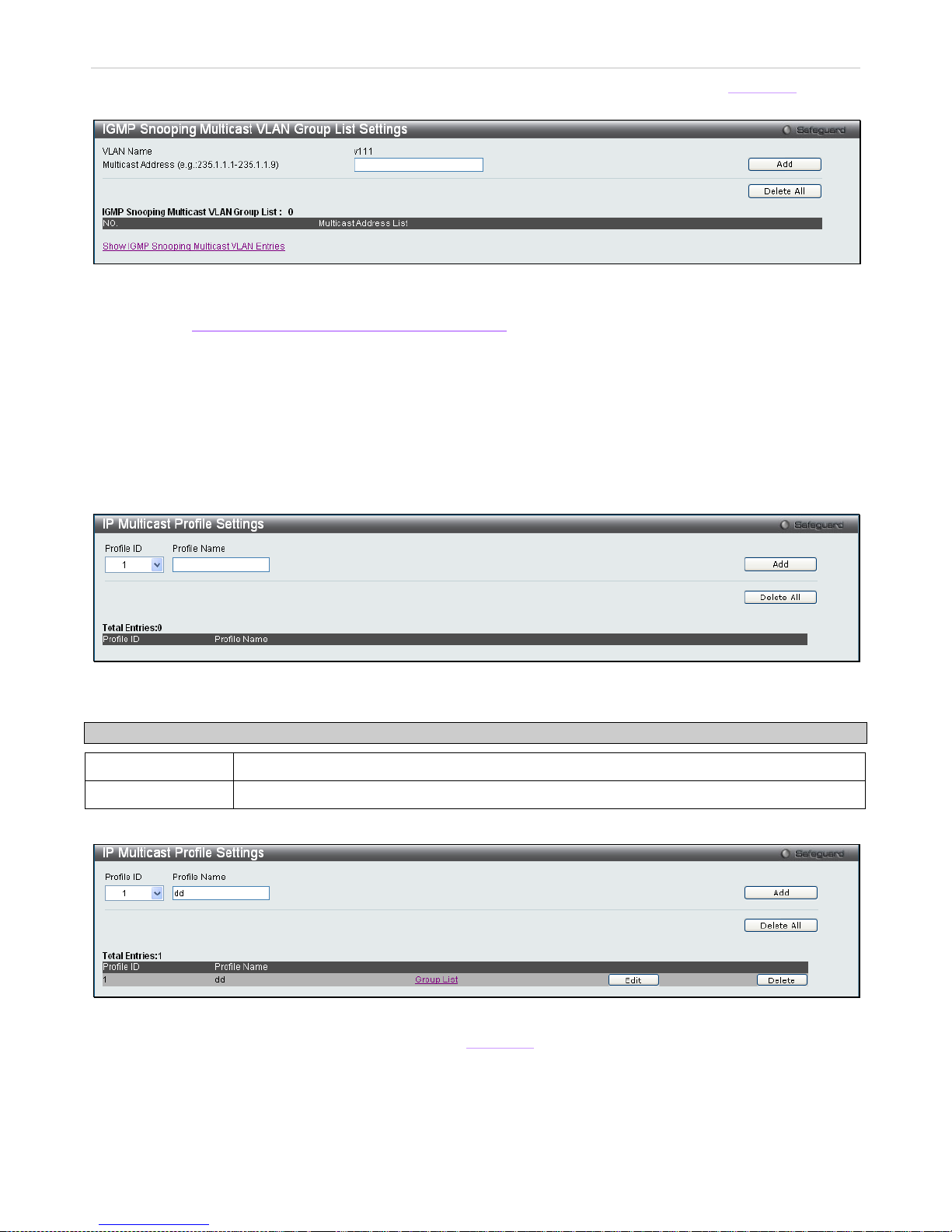
xStack® DES-3200 Series Layer 2 Ethernet Managed Switch WEB UI Reference Guide
88
To add a multicast VLAN to a prof ile that has bee n created, cl ick the correspo nding hyperlink ed Group List to re veal
the following window:
Figure 3 - 31. IGMP Snooping Multicast VLAN Group List Settings window
Enter a Multicast Address and click Add. The new information will be displayed in the table at the bottom of the
window. Click Show IGMP Snooping Multicast VLAN Entries
to return to the IGMP Snooping Multicast VLAN
Settings window. Click Delete All to remove all the entries on this window.
IP Multicast Profile Settings
This window allows the user to add a profile t o which multicast IP address reports are to be received on specified
ports on the Switch. This function will therefore limit the number of reports received and the number of multicast
groups configured on the Switch. The user may set an I P Multicast address or range of IP Mu lticast addresses to
accept reports (Permit) or deny reports (Deny) coming into the specified switch ports.
To view this window, click L2 Features > IGMP Snooping > IP Multicast Profi le Se ttings:
Figure 3 - 32. IP Multicast Profile Settings window
The following fields can be set
Parameter Description
Profile ID
Use the drop-down menu to choose a Profile ID.
Profile Name
Enter a name for the IP Multicast Profile.
To edit and entry click the corresponding Edit button and to delete an entry click the corresponding Delete button.
Figure 3 - 33. IP Multicast Profile Settings (Edit) window
To configure the Group List Settings click the hyperlinked Group List. The follow in g windo w will appear :
Page 90
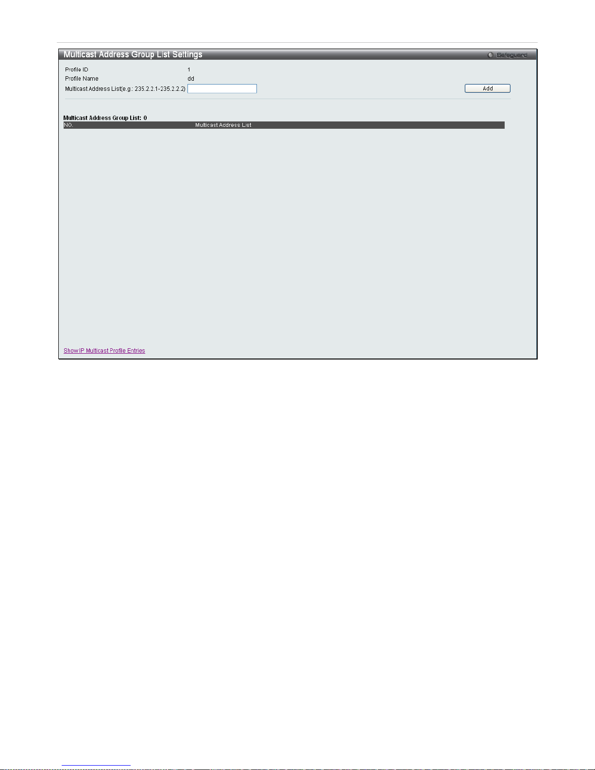
xStack® DES-3200 Series Layer 2 Ethernet Managed Switch WEB UI Reference Guide
89
Figure 3 - 34. Multicast Address Group List Settings window
Enter the Multicast Address List starting with the lowest in the range, and click Add. To return to the IP Multicast
Profile Settings window, click the <<Back button.
Page 91
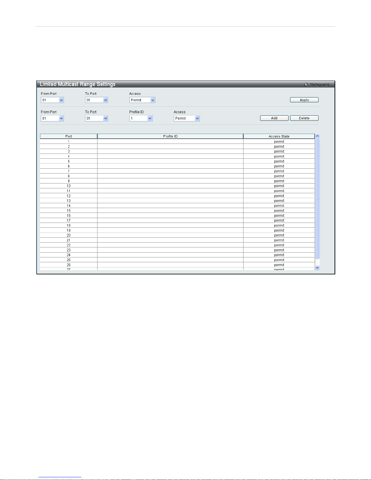
xStack® DES-3200 Series Layer 2 Ethernet Managed Switch WEB UI Reference Guide
90
Limited Multicast Range Settings
This window enables the user to configure the ports on the Switch that will be involved in the Limited IP Multicas t
Range. The user can c onfigure t he range of ports and ass ociate an I P Multic ast Pr ofile to al low or d isal low I GMP jo in
requests to multicast groups defined in the prof ile .
To configure these settings, click L2 Features > IGMP Snooping > Limited Multicast Range Settings:
Figure 3 - 35. Limited Multicast Range Settings window
To add a new range enter the information and click Add, to delete an entry enter the information and click Delete.
Max Multicast Group Settings
This windo w allo ws use rs to c onfigure the p orts on t he S witch that will b e a part of the maximum number of m ulticast
groups that can be learned. To add a new Max Multicast Group, enter the information and click Apply.
To view this window, click L2 Features > IGMP Snooping > Max Multicast Group Settin g s:
Page 92
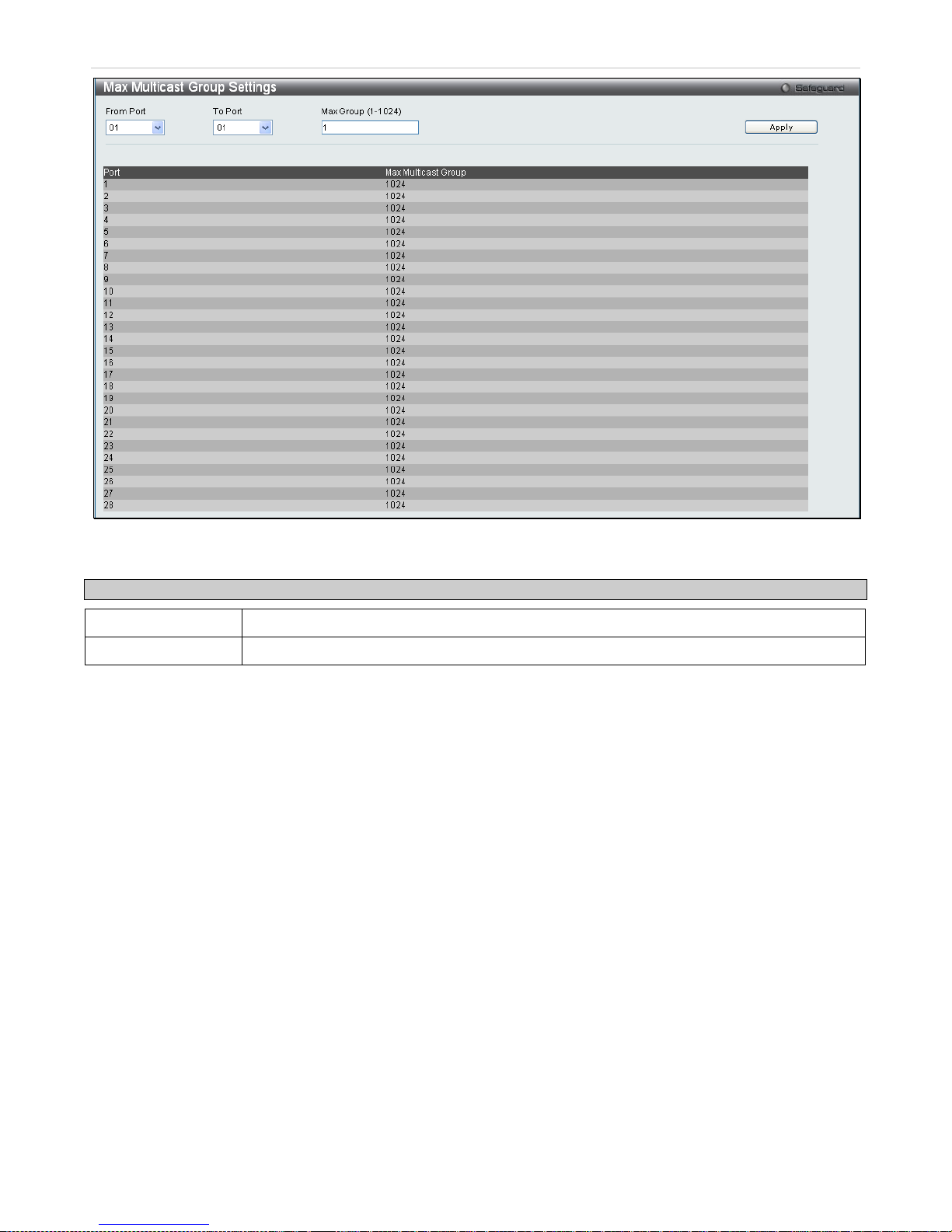
xStack® DES-3200 Series Layer 2 Ethernet Managed Switch WEB UI Reference Guide
91
Figure 3 - 36. Max Multicast Group Settings window
The following fields can be set:
Parameter Description
From Port/To Port
Use the drop-down menus to choose a range of ports.
Max Group (1-1024) Enter the maximum number of the multicast groups. The range is from 1 to 1024.
MLD Snooping Settings
Multicast Listener D isc over y (MLD) Snooping is a n I Pv 6 f unc tio n us e d similarly to IGMP sn oop in g i n I P v4. I t i s us ed t o
discover ports on a VLA N that are requesting multicast data. Instead of flooding all ports on a s elected VLAN with
multicast traffic, MLD snoo ping will only for ward multicast data t o ports that wish to rec eive this data throug h the use
of queries and reports produced by the requesting ports and the source of the multicast traffic.
MLD snooping is accomplished through the examination of the layer 3 part of an MLD control packet transferred
between end nodes a nd a MLD r o uter. When the Switc h disc o vers tha t this route is reques tin g multicast traffic, it a dds
the port directly attached to it into the c orrect IPv6 multicast table, and begins the proces s of forwarding multicast
traffic to that port. This entr y in the multicast rout ing table records the port, the VLAN ID and the assoc iated multicast
IPv6 multicast group addr ess and then consider s this port to be a ac tive listening port . The active listenin g ports are
the only ones to receive multicast group data.
The Switch supports both MLD Snoop ing versi on 1 and MLD ver sio n 2.
MLD Control Messages
If implementing MLD snooping version 1, three types of messages are transferred between devices. These three
messages are all defined by three ICMPv6 packet headers, labeled 130, 131, and 132.
1. Multicast Listener Query, Version 1 – Similar to t he IG MPv2 H ost Mem bers hip Query for IPv4, and label ed
as 130 in the ICMPv6 packet header, this message is sent by the router to ask if any link is requesting
multicast data. There are two types of MLD query messages emitted by the router. The General Query is used
to advertise all multicast addresses that are ready to send multicast data to all listening ports, and the
Multicast Specific quer y, which ad vertises a specif ic multicast addres s that is als o ready. These t wo types of
messages are distinguis hed by a multicast destination address located in the IPv6 header and a multicast
address in the Multicast Listener Query Message.
Page 93
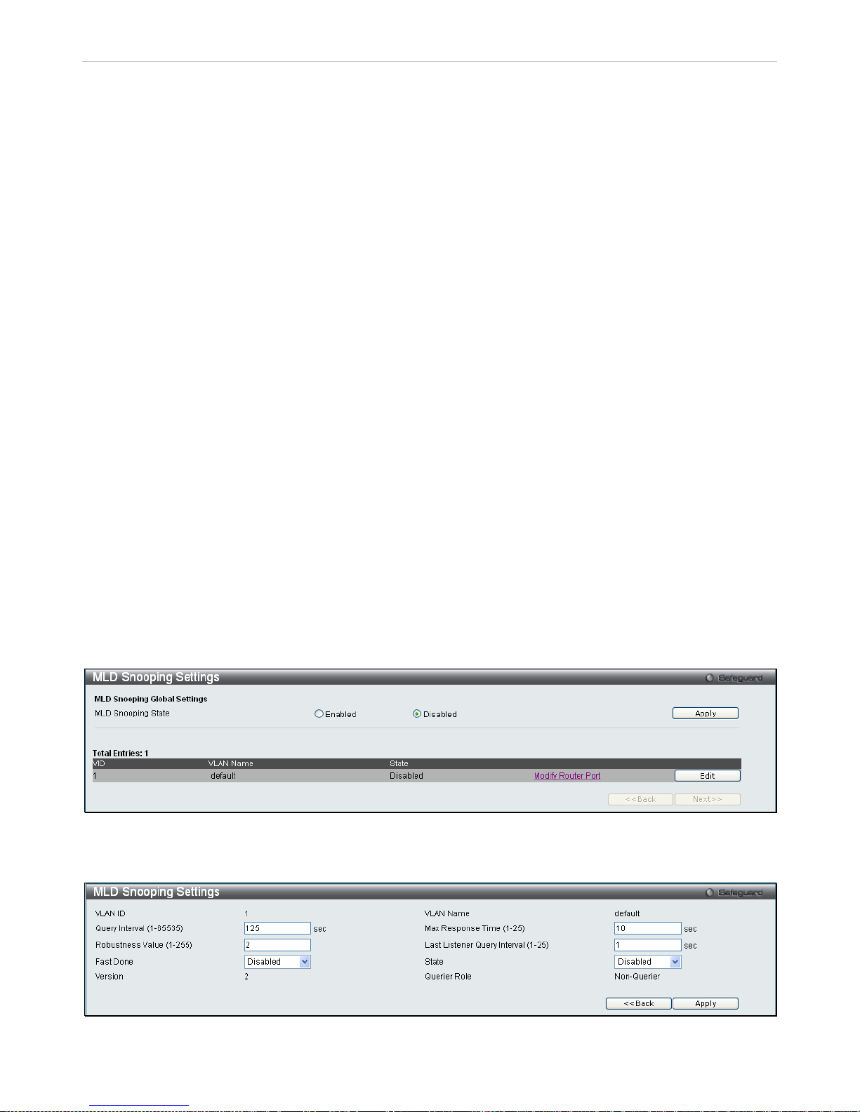
xStack® DES-3200 Series Layer 2 Ethernet Managed Switch WEB UI Reference Guide
92
2. Multicast Listener Report , Version 1 – Comparable to the Host Mem ber s hip Re port in IG M Pv2, an d label e d
as 131 in the ICMP packet header, this m essage is sent by the list ening port to the S witch stating that it is
interested in receiving m ulticast data from a multicast address in respons e to the Multicast Listener Query
message.
3. Multicast Listener Done – Akin to the Lea ve Group Message in IGMPv2, and labe led as 132 i n the ICMP v6
packet header, this mes sage is sent by the multicast listening port stating that it is no longer interested i n
receiving multicast dat a from a specific multicast group address, therefore stating that it is “done” with the
multicast data from this address. Once this message is received by the Switch, it will no longer forward
multicast traffic from a specific multicast group address to this listening port.
If implementing MLD snooping vers ion 2, two types of messages are transf er red b etween devices. T he t wo m ess ages
are defined by two ICMPv6 packet headers, labeled 130 and 143.
1. Multicast Listener Query, Version 2 – Sim ilar to the IGMPv3 Membership Quer y for IPv4, and labeled as
130 in the ICMP v6 pack et header, t his m essage is sent b y the ro uter to ask if any link is requesting m ulticast
data. With MLD snooping ver sion 2, there are three t ypes of MLD query mess ages emitted by the router, as
described below:
• The router sends a G eneral Quer y message t o learn whic h multicast a ddresses have listeners on an
attached link. In a Gener al Query, both the Mult icast Address field an d the Number of Sourc es field
are set to zero.
• The router sends a Multicast Address Specific Query message to learn if a particular multicast
address has any listeners on an attached link. In a Multic ast Address Specific Quer y, the Multicast
Address field contains the multicast address that the router is interested in, while the Number of
Sources field is set to zero.
• The router sends a M ulticast Address and Source Spec ific Query to learn if any of the sources from
the specified list for the partic ular m ulticast addres s has any listeners on an attac hed link or not. In a
Multicast Address and Source Specific Query the Multicast Address field contains the multicast
address that the router is interested in, while the Source Address field(s) contain(s) the source
address(es) that the router is interested in.
2. Multicast Listener Report, Version 2 - Comparable to the H ost M em bership Re port in IG MPv 3, and label ed
as 143 in the ICMP packet header, this m essage is sent by the listening port to the Switc h stating that it is
interested in receiving m ulticast data from a multicast address in respons e to the Multicast Listener Query
message.
This window is used to enable MLD Snooping on the Switch and to configure the settings for MLD snooping. To
enable the MLD Snooping State, click the Enable radio button under MLD Snooping Global Settings and click Apply.
To view this window, click L2 Features > MLD Snooping Settings:
Figure 3 - 37. MLD Snooping Settings window
To configure the settings for an existing entry click the corresponding Edit button which will display the following
window.
Figure 3 - 38. MLD Snooping Settings (Edit) window
Page 94
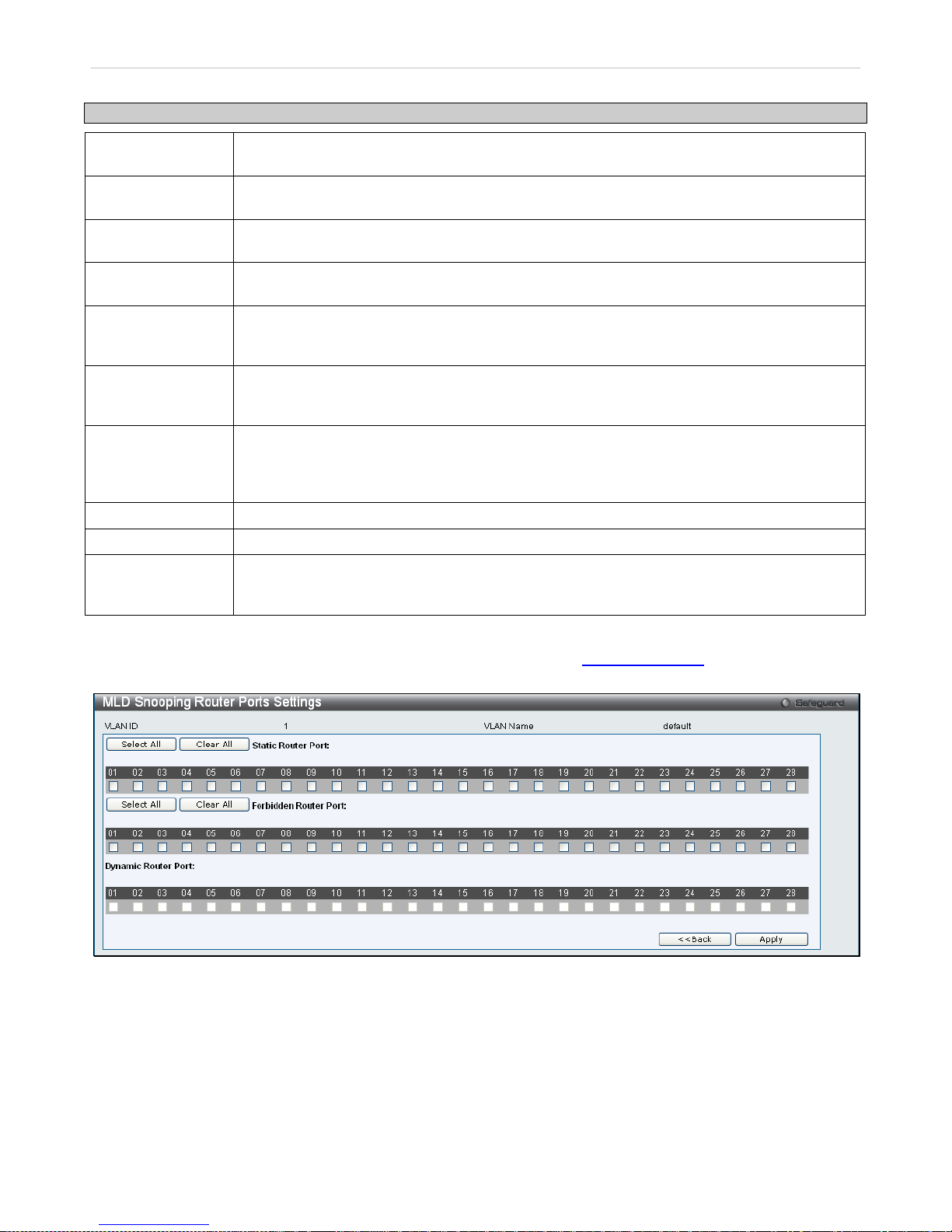
xStack® DES-3200 Series Layer 2 Ethernet Managed Switch WEB UI Reference Guide
93
The following parameters may be viewed or modified:
Parameter Description
VLAN ID
This is the VLAN ID th at, along with the VLAN Nam e, identifies the VLAN f or which the user
wishes to modify the MLD Snooping Settings.
VLAN Name
This is the VLAN Nam e that, along with the VLAN ID , identifies the VLAN f or which the user
wishes to modify the MLD Snooping Settings.
Query Interval
(1-65535)
The Query Interval f iel d is us ed to s et t he time (in seconds) b et ween transmitting ML D quer ies .
Entries between 1 and 65535 seconds are allowed. The default is 125.
Max Response
Time (1-25)
This determines the max imum amount of time in seconds to wait for reports from members.
The Max Response Time field allows an entry between 1 and 25 (seconds). The default is 10.
Robustness Value
(1-255)
Adjust this variable acc ording to expec ted packet loss . If pack et loss on the VLA N is expected
to be high, the Robustnes s Variable should be increased to accomm odate increased packet
loss. This entry field allows an entry of 1 to 255. The defau lt is 2.
Last Listener
Query Interval
(1-25)
This field specifies the maximum amount of time between group-specific query messages,
including those sent in response to leave group messages. The default is 1.
Fast Done This parameter allows the user to enable the Fast Leave func tion. Enabled, this function will
allow members of a multicast group to leave the group immediately (without the
implementation of the Last Listener Query Interval) when an MLD Leave Report Packet is
received by the Switch. The default is Disabled.
State Select Enabled to implement MLD Snooping. This field is Disabled by default.
Version
The read-only field displays the MLD version used on the Switch, 2.
Querier Role
This read-only field describes the behavior of the Switch for sending query pack ets . Queri er will
denote that the Switch is sending out MLD query packets. Non-Querier will denote that the
Switch is not sending out MLD query packets.
Click Apply to implement any changes made and <<Back to return to the initial MLD Snooping Settings window.
To modify the MLD Snooping Router Port Settings, click on the hyperlinked Modif y Router Por t , which will show the
following window for the user to configure:
Figure 3 - 39. MLD Snooping Router Ports Settings window
Select the desired router ports and t hen click Apply to implem ent any ch anges m ade. T o select either al l of the s tatic
router ports or all of the for bidden router ports, click the corresponding Select All button. To clear eith er all of the
selected static router por ts or all of the selec ted forbid den router por ts, clic k the cor responding C lear All button. Click
<<Back to return to the MLD Snooping Settings window.
Page 95
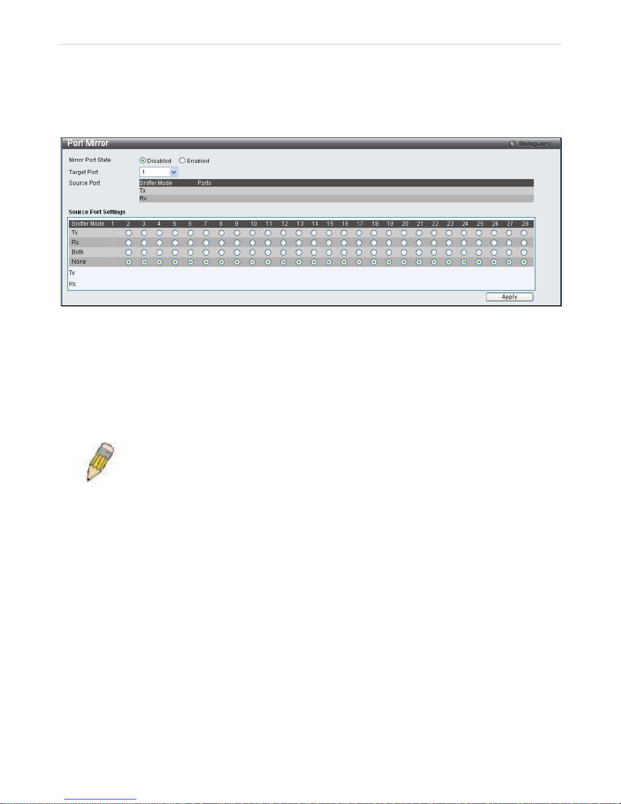
xStack® DES-3200 Series Layer 2 Ethernet Managed Switch WEB UI Reference Guide
94
Port Mirror
The Switch allows you to c opy fram es transm itted and rec eived on a por t and redir ect the copies to another port. You
can attach a monitoring device to t he mirrored port, such as a sniffer or an RMO N probe, to view details about the
packets passing through the first port. This is useful for network monitoring and troubleshooting purposes.
To view this window, click Layer 2 Features > Port Mirror:
Figure 3 - 40. Port Mirror window
To configure a mirror port:
1. Change the status to Enabled.
2. Select the Target Port, which receives the copies from the source port.
3. Select the Source Port from where the frames come from.
4. Click Apply to let the changes take effect.
NOTE: You cannot mirror a f ast port onto a slower por t. For example, if you tr y to mirror the
traffic from a 100 Mbps port onto a 10 M bps port, t his can caus e throughp ut pro blem s. The por t
you are copying f rames from should alwa ys support an equal or lower speed than the por t to
which you are sendi ng the c opies. A lso, t he targe t p ort for the m irroring cann ot b e a m em ber of
a trunk group. Please note a target port and a source port cannot be the same port.
Loopback Detection Settings
The Loopback Detection function is used to detect the loop create d by a s pecific port. Choose t he loopb ack detection
operation mode. Two modes are supported, port based and VLAN based. In the port-based m ode, the port will be
shut-down (be disabled) when a l oop is detec t ed; i n VL AN-based mode, the port cannot process pac kets on the VLAN
on which the loop is detect ed. The default m ode is port-based. T he Loopback Detection port or VLAN will res tart (be
able to forwarding) when the Loopback D etection Rec over Time times out. The Loop back Detection function c an be
implemented on a range of ports at a time. The user may enable or disable this function using the pull-down menu.
Page 96
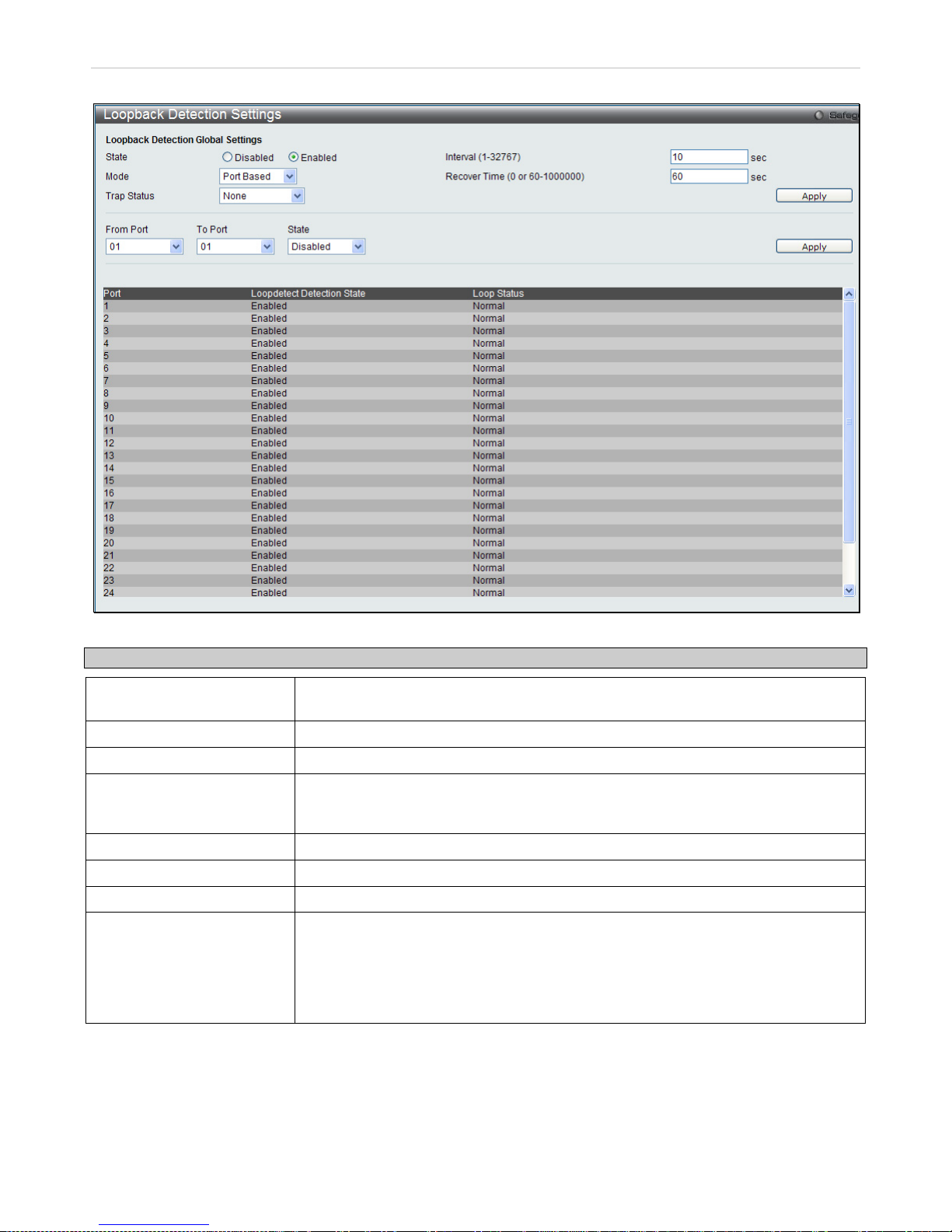
xStack® DES-3200 Series Layer 2 Ethernet Managed Switch WEB UI Reference Guide
95
To view this window, click L2 Features > Loopback Detection Settings:
Figure 3 - 41. Loopback Detection Settings window
Parameter Description
State
Use the drop-down menu to enable or disable loopback detection. The default is
Disabled.
Interval (1-32767) Set a loop-detect Interval between 1 and 32767 seconds. The default is 10 seconds.
Mode Choose Port Based or VLAN Based.
Recover Time
(0 or 60-1000000)
Time allowed (in seconds) for recovery when a loopback is detected. The Loop-detect
Recover Time can be set at 0 seconds, or 60 to 1000000 seconds. Entering 0 will
disable the Loopdetect Recover Time. The default is 60 seconds.
From Port
Use the drop-down menu to select a beginning port number.
To Port
Use the drop-down menu to select an ending port number.
State Use the drop-down menu to toggle between Enabled and Disabled.
Trap Status
Choose the condition for sending traps. The options are:
Loop Detected - Trap is sent when the loop condition is detected.
Loop Cleared - Trap is sent when the loop condition is cleared.
None – Do not send a trap for loopback detection. This is the default status.
Both – Send both cleared and detected traps.
Click Apply to implement changes made.
Page 97

xStack® DES-3200 Series Layer 2 Ethernet Managed Switch WEB UI Reference Guide
96
Spanning Tree
This Switch supports three vers ions of the Spanni ng Tree Protoco l: STP, Rapid ST P, and MSTP. STP will b e familiar
to most networking professionals. However, since RSTP and MSTP have been recently introduced to D-Link managed
Ethernet switches, a brief introduct ion to the techno logy is provide d below followed b y a description of how to set up
STP, RSTP, and MSTP.
802.1Q-2005 MSTP
Multiple Spanning Tree Pr otocol, or MST P, is a standard defined by the IEEE comm unity that allows m ultiple VLANs
to be mapped to a single s panning tre e instance, whic h will pro vide m ultiple p athways across the network . Therefor e,
these MSTP configurations wil l balance t he traf fic load , prevent ing w ide scal e disr uptions when a sin gle span ning tr ee
instance fails. This will al low for faster converge nces of new topolo gies for the failed ins tance. Fram es designated for
these VLANs will be proc essed quickly and completely throughou t interconnected bridges utilizing any of the thr ee
spanning tree protocols (STP, RSTP or MSTP).
This protocol will a lso tag BPDU pac kets so rec eiving devices can disting uish spanning tr ee instances , spanning tre e
regions and the VLANs as sociated with them. An MSTI ID will classif y these instances. MSTP will connect multiple
spanning trees with a Com mon and Internal Spanning Tr ee ( CIST ) . The C IST will automatically determine ea ch MSTP
region, its maximum possible extent and will appear as one virtual bridge that runs a single spanning tree.
Consequentially, frames assigned to different VLANs will follow different data routes within administratively
established regions on the net work, c ontinuin g to allo w sim ple and f ull process in g of fr ames, r egardless of adm inistr ative errors in defining VLANs and their respective spanning trees.
Each switch utilizing the M STP on a network will ha ve a single MSTP configur ation that will have the f ollowing three
attributes:
1. A configuration name defined by an alphanumeric string of up to 32 characters (defined in the MST
Configuration Identification window in the Configuration Name field).
2. A configuration revision number (named here as a Revision Level and found in the MST Configuration
Identification window) and;
3. A 4094-element table (def ined here as a VID List in the MST Configuration Identification window), which
will associate each of the possible 4094 VLANs supported by the Switch for a given instance.
To utilize the MSTP function on the Switch, three steps need to be taken:
1. The Switch must be set to the MST P setting (found in the STP Bridge Global Settings window in the STP
Version field)
2. The correct spanning tre e priority for the MSTP insta nce must be entered (defined here as a Priority in the
MSTI Config Information window when configuring MSTI ID settings).
3. VLANs that will b e shared must be ad ded to the MSTP I nstance ID (def ined here as a VID List in the MST
Configuration Identification window when configuring an MSTI ID settings).
Rapid Spanning Tree
The Switch implem ents three v ersions of the Span nin g Tr ee Protoco l, the M ultip le Spann ing T ree Prot ocol ( MST P) as
defined by the IEEE 802.1Q-2005, the Rapid Spanning Tree Protocol (RSTP) as defined by the IEEE 802.1D-2004
specification and a vers ion compatible with the IEEE 802.1D-1998 ST P. RSTP can operate with legacy equipm ent
implementing IEEE 802.1D-1998, however the advantages of using RSTP will be lost.
The Rapid Spanning Tree Protocol (RSTP) evolved from the STP standard. RSTP was developed in order to
overcome some lim itations of STP that im pede the f unc tion of s om e recent s witching inn ovati ons, in par ticula r, c ertain
Layer 3 functions that ar e incr easingl y handled by Eth ernet switc hes. The bas ic functio n and m uch of the te rminolog y
is the same as STP. Most of the settings configured f or STP are also used for RST P. This section introdu ces some
new Spanning Tree concepts and illustrates the main differences between the two protocols.
Page 98

xStack® DES-3200 Series Layer 2 Ethernet Managed Switch WEB UI Reference Guide
97
Port Transition States
An essential differ ence between the thr ee protocols is in the way ports transition to a for warding state an d in the wa y
this transition relates to the role of the port (forw arding or not f orwarding) in the topology. M STP and RSTP c ombine
the transition states dis ab led, b locking and listeni ng us ed in STP and creates a single sta te D isc ardi ng. In either case,
ports do not forward pac kets. In the STP port transiti on states disabled, blocking or lis tening or in the RSTP/MSTP
port state discard ing, there is no f unctional diff erence, the port is not active i n the network topology. The ta ble below
compares how the three protocols differ regarding the port state transition.
All three protocols c alculate a stable topology in t he same way. Every segment will ha ve a single path to the root
bridge. All bridges listen for BPDU packets. However, BPDU packets are sent more frequently - with every Hello
packet. BPDU pack ets are sent even if a BPDU packet was not rece ived. Therefore, each link between bridges is
sensitive to the status of the link. Ultimately this difference results in faster de tection of failed links, and thus faster
topology adjustment. A drawback of STP is this absence of immediate feedback from adjacent bridges.
MSTP RSTP STP Forwarding Learning
Disabled Disabled Disabled No No
Discarding Discarding Blocking
No No
Discarding Discarding Listening
No No
Learning Learning Learning
No
Yes
Forwarding Forwarding Forwarding Yes Yes
Table 3 - 1. Comparing Port States
RSTP is capable of a m ore rapid transition to a forwarding state - it no longer relies on tim er configurations - RSTP
compliant bridges are sens itive to f eedback from other RST P com pliant brid ge link s. Ports d o not ne ed to w ait for the
topology to stabilize before transitioning to a forwarding state. In order to allow this rapid transition, the protocol
introduces two new variables: the edge port and the point-to-point (P2P) port.
Edge Port
The edge port is a configurable designation used for a port that is directly connected to a segment where a loop
cannot be created. An example wou ld be a port conn ected directl y to a single w orkstation. Ports that are designated
as edge ports transit ion to a forwardin g state imm ediately without going through the l istening and lear ning states. An
edge port loses its status if it receives a BPDU packet, immediately becoming a normal spanning tree port.
P2P Port
A P2P port is also capable of rapid transition. P2P ports may be used to connect to other bridges. Under RSTP/MSTP,
all ports operating in full-duplex mode are considered to be P2P ports, unless manually overridden through
configuration.
STP/RSTP/MSTP Compatibility
MSTP or RSTP can interoper ate with legacy equipment and is capab le of automatically adjusting BPDU packets to
STP format when neces sary. However, any segment using ST P will not benefit from the rapid tr ansition and rapid
topology change det ec tion of MSTP or RSTP. The protocol also pr o v ides for a variable used for migration in the ev en t
that legacy equipment on a segment is updated to use RSTP or MSTP.
The Spanning Tree Protocol (STP) operates on two levels:
1. On the switch level, the settings are globally implemented.
2. On the port level, the settings are implemented on a per user-defined group of ports basis.
Page 99
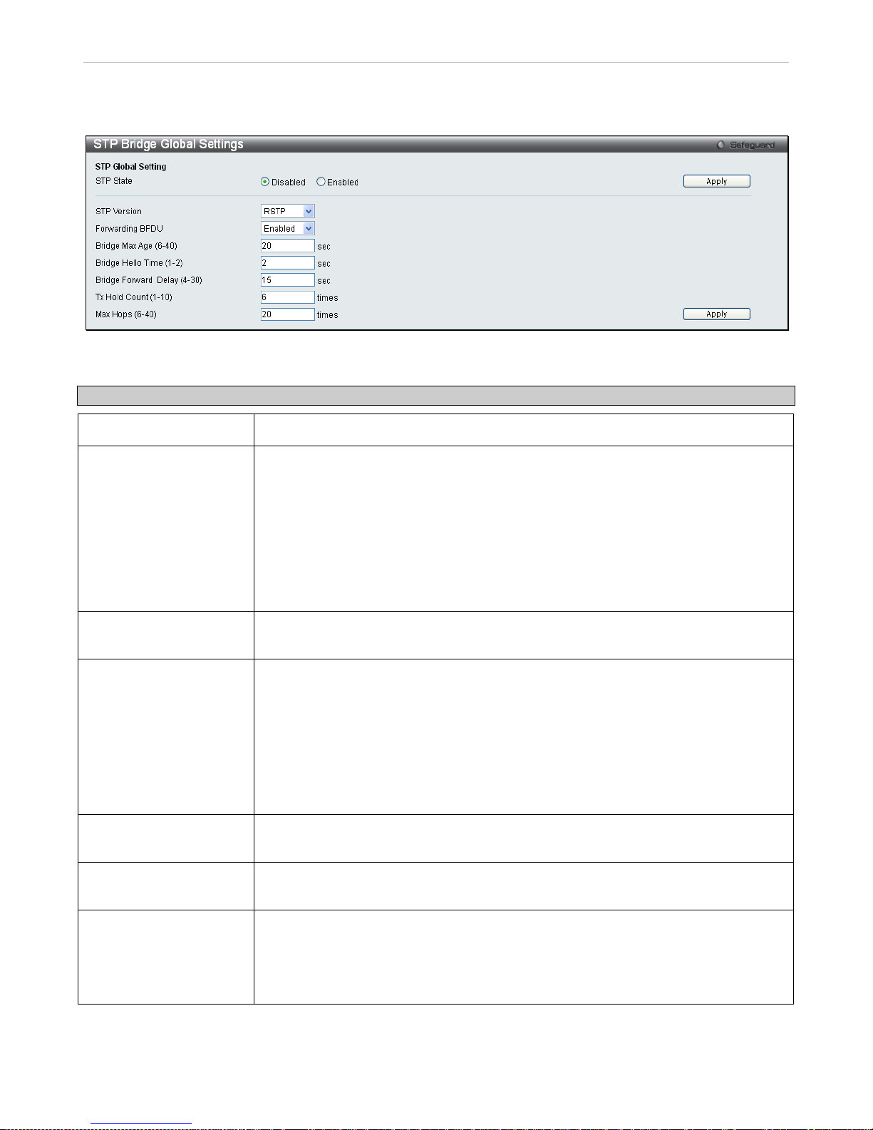
xStack® DES-3200 Series Layer 2 Ethernet Managed Switch WEB UI Reference Guide
98
STP Bridge Global Settings
To open the following window, click L2 features > Spanning Tree > STP Bridge Global Settings:
Figure 3 - 42. STP Bridge Global Settings window
The following parameters can be set:
Parameter Description
STP State
Use the radio buttons to enable or disable the STP Status.
STP Version
Use the pull-down menu to choos e the d es ired ver sio n of STP to be implemented on the
Switch. There are three choices:
STP - Select this parameter to set the Spanni ng Tree Protocol (STP) globally on the
switch.
RSTP - Select this parameter to s et the Rapid Spa nning Tree Prot ocol (RSTP) global ly
on the Switch.
MSTP − Select this parameter to set the Multiple Spanning Tree Protocol (MSTP)
globally on the Switch.
Forwarding BPDU This field can be Enabled or Disabled. When Enabled, it allo ws the forwarding of STP
BPDU packets from other network devices. The default is Enabled.
Bridge Max Age (6-40)
The Max Age may be set to ensure that old information does not endlessly circulate
through redundant paths in the network , preventing th e effec tive propagation of the new
information. Set b y the Ro o t Bri dge , t h is val ue wi ll aid in deter m ining that the S witch has
spanning tree configuratio n values consistent with other devices on the br idged LAN. If
the value ages ou t and a BPDU has stil l not been received from the Root Bridge, the
Switch will start send ing its own BPDU to all other switc hes for permission to becom e
the Root Bridge. If it turns out that your switch has the lowes t Bridge Identifier , it will
become the Root Bridge. The user may choose a tim e between 6 and 40 seconds. The
default value is 20.
Bridge Forward Delay
(4-30)
The Forward Dela y can be f rom 4 to 30 seconds. Any port on the Switch spen ds this
time in the listening state while moving from the blocking state to the forwarding state.
Tx Hold Count (1-10)
Used to set the max imum number of Hello pack ets transmitted per interval. T he count
can be specified from 1 to 10. The default is 6.
Max Hops (6-40)
Used to set the number of hops bet ween devices in a spanning tree reg ion before the
BPDU (bridge protocol data unit) packet sent by the Switch will be discarded. Each
switch on the hop cou nt will reduce th e hop count by one until the value reac hes zero.
The Switch will then disc ard the BPDU packet and t he information held for the port will
age out. The user may set a hop count from 6 to 40. The default is 20.
Click Apply to implement changes made.
Page 100
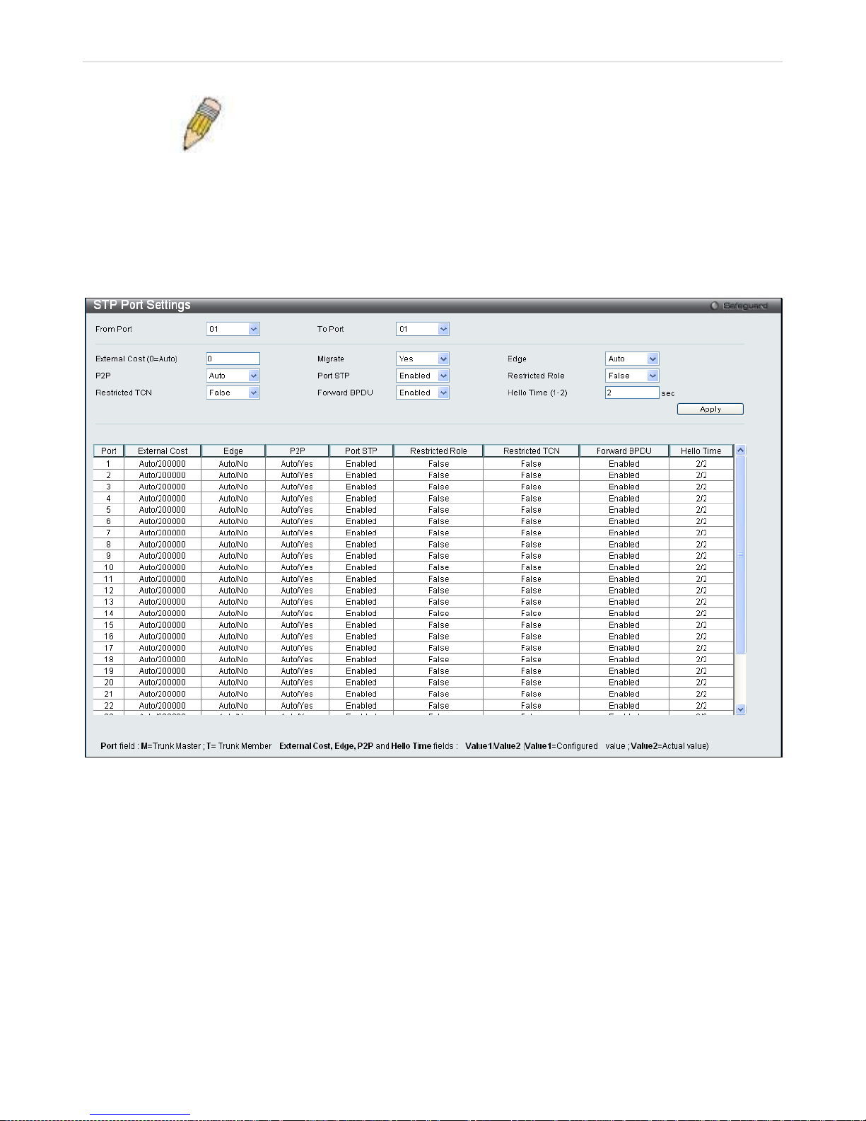
xStack® DES-3200 Series Layer 2 Ethernet Managed Switch WEB UI Reference Guide
99
NOTE: The Hello Time c annot be longer th an the Max. Age. Otherwise, a
configuration error will occ ur. Observ e the f ollowing form ulas when s etting
the above parameters:
Max. Age ≤ 2 x (Forward Delay - 1 second)
Max. Age ≥ 2 x (Hello Time + 1 second)
STP Port Settings
STP can be set up on a port per port basis.
To view the following window, click L2 Features > Spanning Tree > STP Port Settings:
Figure 3 - 43. STP Port Settings window
In addition to setti ng Spanning T ree param eters for us e on the switc h level, the Switch allo ws for the conf iguration of
groups of ports, each port-group of which will have its own spanning tree, and will require some of its own
configuration settings . An STP Group will use the s witch-level parameters entered above, with the addition of Port
Priority and Port Cost.
An STP Group spanning tree works in the sam e way as the switch-l evel spannin g tree, but the root brid ge concept is
replaced with a roo t por t co ncept. A root por t is a por t of the gr oup t hat is e lected based on p ort priorit y and port c ost,
to be the connection to the net work for the group. R edunda nt link s will be b lock ed, jus t as redundant links are block ed
on the switch level.
The STP on the s witch level blocks redundant links between switches (and similar network devices). The port level
STP will block redundant links within an STP Group.
It is advisable to define an STP Group to correspond to a VLAN group of ports.
 Loading...