

Page 1

©Copyright 2009. All rights reserved
User Manual
Product Model: DAS-3626
VDSL2 Switch
Release 1.00
Page 2

DGS-3700-12/DGS-3700-12G Series Layer 2 Gigabit Ethernet Switch User Manual
_________________________________________________________________________________
Information in this document is subject to change without notice.
© 2009 D-Link Corporation. All rights reserved.
Reproduction in any manner whatsoever without the written permission of D-Link Corporation is strictly forbidden.
Trademarks used in this text: D-Link and the D-LINK logo are trademarks of D-Link Corporation; Microsoft and Windows are registered trademarks
of Microsoft Corporation.
Other trademarks and trade names may be used in this document to refer to either the entities claiming the marks and names or their products.
D-Link Corporation disclaims any proprietary interest in trademarks and trade names other than its own.
October 2009 P/N 651EV3726015G
ii
Page 3

DAS-3626 VDSL2 Switch User Manual
Table of Contents
Web-based Switch Configuration .................................................................................................................................... 6
System Configuration .................................................................................................................................................... 14
Switch Configuration ...................................................................................................................................................... 26
VDSL Configuration ....................................................................................................................................................... 53
Multicasting .................................................................................................................................................................... 59
Storm Control ................................................................................................................................................................ 74
QoS ............................................................................................................................................................................... 76
ACL ............................................................................................................................................................................... 84
VLAN ........................................................................................................................................................................... 103
Security ........................................................................................................................................................................ 109
CPE Management ....................................................................................................................................................... 122
Status .......................................................................................................................................................................... 135
Maintenance ................................................................................................................................................................ 154
System Log Entries ..................................................................................................................................................... 163
Glossary ...................................................................................................................................................................... 174
Password Recovery Procedure ................................................................................................................................... 176
iii
Page 4

DAS-3626 VDSL2 Switch User Manual
Preface
The DAS-3626 User Manual is divided into sections that describe the system installation and operating instructions.
Section 2 through Section 13 corresponds to a menu folder in the web management interface presented in the same
order they appear in the web interface.
Section 1, Introduction to Web-based Switch Management – Describes how to connect to and use the Webbased switch management feature on the switch.
Section 2, System Configuration – Details for configuring some of the basic functions of the switch including
System Information, IP Settings, Interface Settings, IPv6 Neighbor Settings, User Accounts, SNTP Settings and
System Log Configuration. The Quick Configuration section of the home page includes a few menus that are not
accessable in the main menu folders; these menus are featured in this section as well.
Section 3, Switch Configuration – This section describes menus common to Layer 2 switching for configuration of
MAC Address Aging, Port Mirroring, Ethernet Settings, Traffic Segmentation, Forwarding Database configuration,
CLI Paging, Port Mirroring, Port Trunks, LACP Port configuration, Loopback Detection setting, GVRP, DHCP Relay
and Spanning Tree Protocol/Multiple Spanning Tree and CFM settings.
Section 4, VDSL Configuration – Settings for configuration of VDSL Profiles, VDSL Ports and various VDSL
Status display menus are located here.
Section 5, Multicasting – Configuration menus for IGMP Snooping, Multicast Profile, Limited Range, Group
settings and Multicast Listener Discovery (MLD) configuration.
Section 6, Storm Control – Configuration menus for multicast and broadcast storm control.
Section 7, QoS – Information for Quality of Service configuration. Menus include Bandwidth Control, 802.1P Default
Priority, 802.1P User Priority, QoS Scheduling Mechanism, QoS Scheduling and In Band Manage Settings.
Section 8, ACL Configuration – Menus for configuration of ACL including the ACL Configuration Wizard, Access
Profile List and ACL Finder.
Section 9, VLAN – Information for configuration of 802.1Q VLANs, 802.1v Protocol VLAN configuration.
Section 10, Security – Features information on security functions, including Safeguard Engine, Trusted Host, Port
Security , MAC Spoofing Access, SSL setting, SSH setting and Access Authentication Control settings.
Section 11, CPE Management – Menus for configuration, upgrade and testing of remote CPE equipment and client
LAN settings.
Section 12, Status – Features information about the monitoring switch and network functions including CPU
Utilization, Port Utilization, Packet Size, Memory Utilization, Packets, Errors, System Log, Ping Test, VDSL
monitoring and system Firmware Information.
Section 13, Maintenance – Menus for Firmware Upgrade, Configuration File Backup and restore, as well as the
SNMP Settings menu folder are also located in the Maintenance folder.
Appendix A, System Log Entries – This table lists all the possible entries and their corresponding meanings that
will appear in the System Log of this switch.
Appendix B, Glossary – Lists definitions for terms and acronyms used in this document.
Appendix C, Password Recovery Procedure - This section describes the procedure for resetting passwords on
D-Link switches.
iv
Page 5
DAS-3626 VDSL2 Switch User Manual
Intended Readers
The DAS-3626 User Manual Manual contains information for setup and management of the switch. This manual is
intended for network managers familiar with network management concepts and terminology.
Typographical Conventions
Convention Description
[ ] In a command line, square brackets indicate an optional entry. For example: [copy
filename] means that optionally you can type copy followed by the name of the file. Do not
type the brackets.
Bold font Indicates a button, a toolbar icon, menu, or menu item. For example: Open the File menu
and choose Cancel. Used for emphasis. May also indicate system messages or prompts
appearing on your screen. For example: You have mail. Bold font is also used to
represent filenames, program names and commands. For example: use the copy
command.
Boldface Typewriter
Font
Indicates commands and responses to prompts that must be typed exactly as printed in
the manual.
Initial capital letter Indicates a window name. Names of keys on the keyboard have initial capitals. For
example: Click Enter.
Italics Indicates a window name or a field. Also can indicate a variables or parameter that is
replaced with an appropriate word or string. For example: type filename means that you
should type the actual filename instead of the word shown in italic.
Menu Name > Menu
Option
Menu Name > Menu Option Indicates the menu structure. Device > Port > Port
Properties means the Port Properties menu option under the Port menu option that is
located under the Device menu.
Notes, Notices, and Cautions
A NOTE indicates important information that helps you make better use of your device.
A NOTICE indicates either potential damage to hardware or loss of data and tells you
how to avoid the problem.
A CAUTION indicates a potential for property damage, personal injury, or death.
5
Page 6
DAS-3626 VDSL2 Switch User Manual
Section 1
Web-based Switch Configuration
Introduction
Out-of-Band Access to System Management
Interface IP Settings for Switch Management
Login to Web Manager
Web-based User Interface
Web Pages
Introduction
All software functions of the switch can be managed, configured and monitored via the embedded web-based (HTML)
interface. The switch can be managed from remote stations anywhere on the network through a standard browser
such as Microsoft Internet Explorer.
The web-based management module and command line interface (console program or Telnet) are different ways to
access the same internal switching software and configure it. Thus, all settings encountered in web-based
management are the same as those found in the command line interface (CLI).
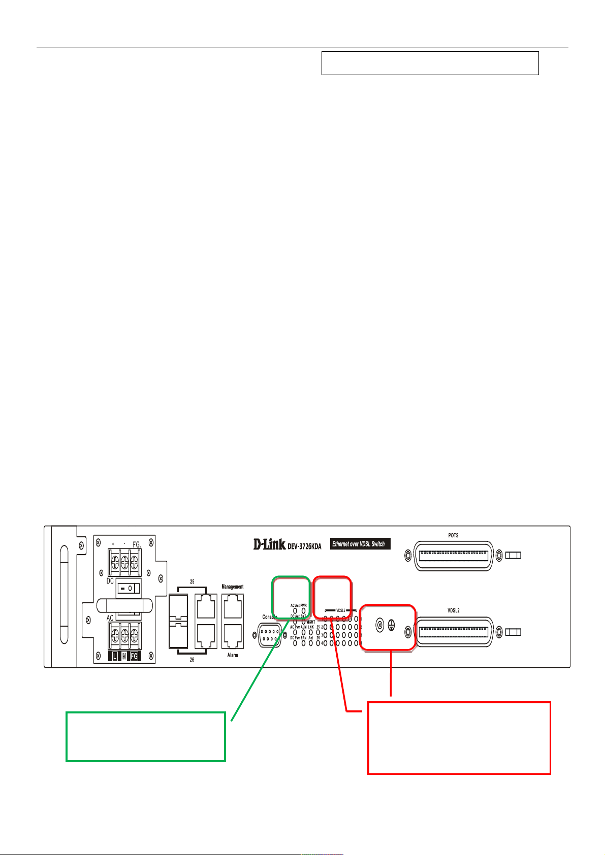
Out-of-Band Access to System Management
Management access to the System can be done out-of-band with a physical connection directly to the switch. Connect
to the RS-232 Console serial port on the front panel, or use the Mangament Ethernet port located next to the
Console port. Use standard terminal emulation software for Console port access as described in the CLI Command
Reference Manual. Use of the Management port provides the options of using either the web-based management
module or the command line interface via Telnet. The Management port must reside on a different subnet than the inband System interface. The default IP settings for the Management port are 192.168.1.10/255.255.255.0 while the
default IP settings for the in-band network interface are 10.90.90.90/255.0.0.0. See below for instructions on how to
change the IP settings for the in-band and out-of-band interfaces used for switch management. For more information
about physical ports and other hardware information please see the Hardware Manual.
Figure 1. Front panel in-band and out-of-band ports
Use either Gigabit Ethernet port
(ports 25 and 26) for in-band
access.
Use the Management Ethernet port
(default IP address 192.168.1.10) or
the Console (RS-232) port for outof-band access.
6
Page 7
DAS-3626 VDSL2 Switch User Manual
Interface IP Settings for Switch Management
The switch maintains two IP interfaces used for management, one in-band IP interface named System, and one outof-band IP interface named outband. These IP interfaces cannot reside within the same subnet. If the outband
interface is configured with IP settings that place it within the same subnet as the System IP interface, the IP interface
for outband is invalidated.
The default IP settings of the in-band IP interface System are 10.90.90.90/255.0.0.0. The default IP settings for the
ou-of-band IP interface outband are 192.168.1.10/255.255.255.0. The CLI command syntax used to change the IP
settings of the in-band IP interface is config ipif System ipaddress xxx.xxx.xxx.xxx/yyy.yyy.yyy.yyy where the x’s
represent the IP address to be assigned to the IP interface named System and the y’s represent the corresponding
subnet mask. The CLI command syntax used to change the IP settings of the out-of-band IP interface is config ipif
outband ipaddress xxx.xxx.xxx.xxx/yyy.yyy.yyy.yyy. Alternatively you can use CIDR notation for the IP settings,
xxx.xxx.xxx.xxx/z, where the x’s represents the corresponding number of subnets.
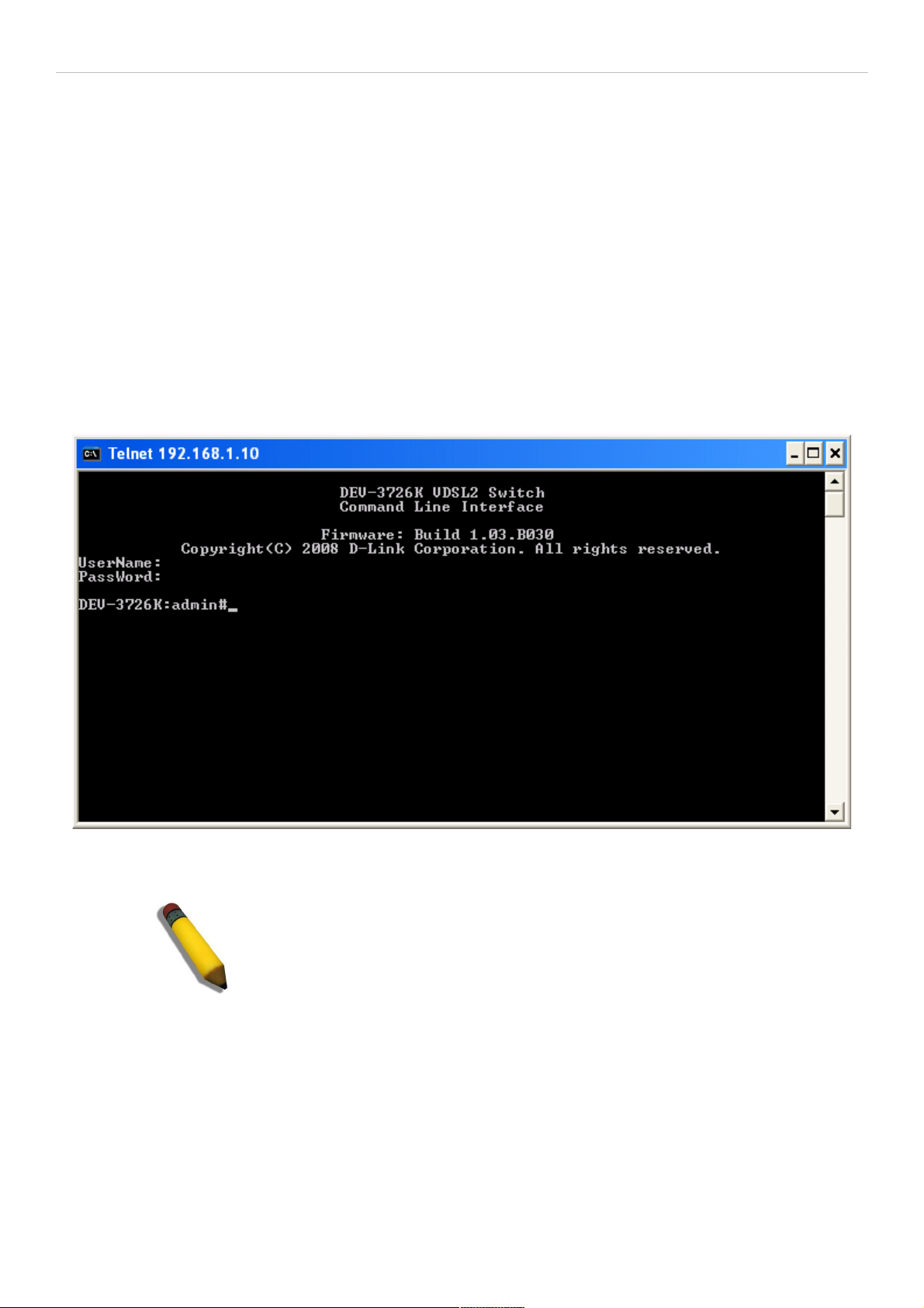
Connection to the switch using Telnet can be done by connecting to the Management Ethernet port and launching the
Windows Command Prompt or similar software. Make sure your computer’s IP settings allow connection to the switch
default IP subnet of the outband interface (192.168.1.0) and Telnet to 192.168.1.10. You will be prompted for a User
Name and Password, there is no default user name or password, simply press the Enter at each prompt to obtain the
administrator’s prompt DAS-3626:admin# as seen in the example below. The switch is not ready for configuration.
Figure 2. Menus Command Prompt using out-of-band Telnet connection
NOTE: Telnet can also be used in-band by connecting through port 25 or
26. The Factory default IP address of the in-band interface “System” is
10.90.90.90.
7
Page 8
DAS-3626 VDSL2 Switch User Manual
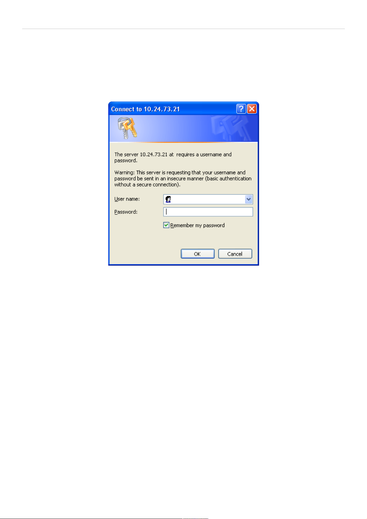
Login to Web Manager
To use the web-based management module for switch management, run the browser you have installed on your
computer and point it to the IP address you have defined for the device. The URL in the address bar should read
something like: http://123.123.123.123, where the numbers 123 represent the IP address of the switch; this opens the
management module's user authentication window, as seen below.
Figure 3. Enter Network Password dialog
There is no default user name or password. At the User Name and Password fields, click on OK. This opens the webbased management interface. Switch management features available in the web-based manager are explained below.
8
Page 9
DAS-3626 VDSL2 Switch User Manual
Web-based User Interface
The user interface provides access to various switch configuration and management windows, allows you to view
performance statistics, and permits you to graphically monitor the system status.
Areas of the User Interface
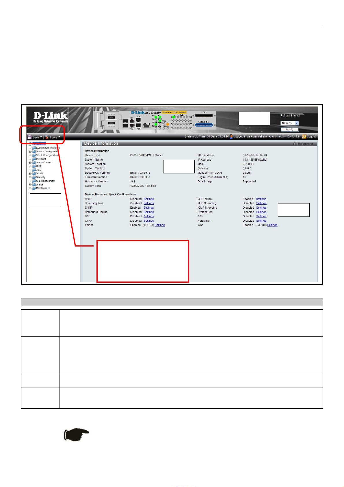
The figure below shows the user interface. The user interface is divided into three distinct areas as described in the
table.
Figure 4. Main Web-Manager page
Area Function
Area 1 Select the folder or window to be displayed. The folder icons can be opened to display the hyper-
linked window buttons and subfolders contained within them. Click the D-Link logo to go to the DLink website.
Area 2 Presents a graphical near real-time image of the front panel of the switch. This area displays the
switch's ports and expansion modules showing port activity.
Various areas of the graphic can be selected for performing management functions, including port
configuration.
Area 3 Presents switch information based on your selection and the entry of configuration data.
Area 4 Links to configuration menus, some of which are not accessable in the configuration menu folders
(displayed in Area 1) are located here.
Save and back up configuration
settings, reboot, reset
configuration and download
firmware drop-down menus.
Area 2
Area 1
NOTICE: Any changes made to the switch configuration during the
current session must be saved using the drop-down Save menu or use
the command line interface (CLI) command save.
9
Page 10
DAS-3626 VDSL2 Switch User Manual
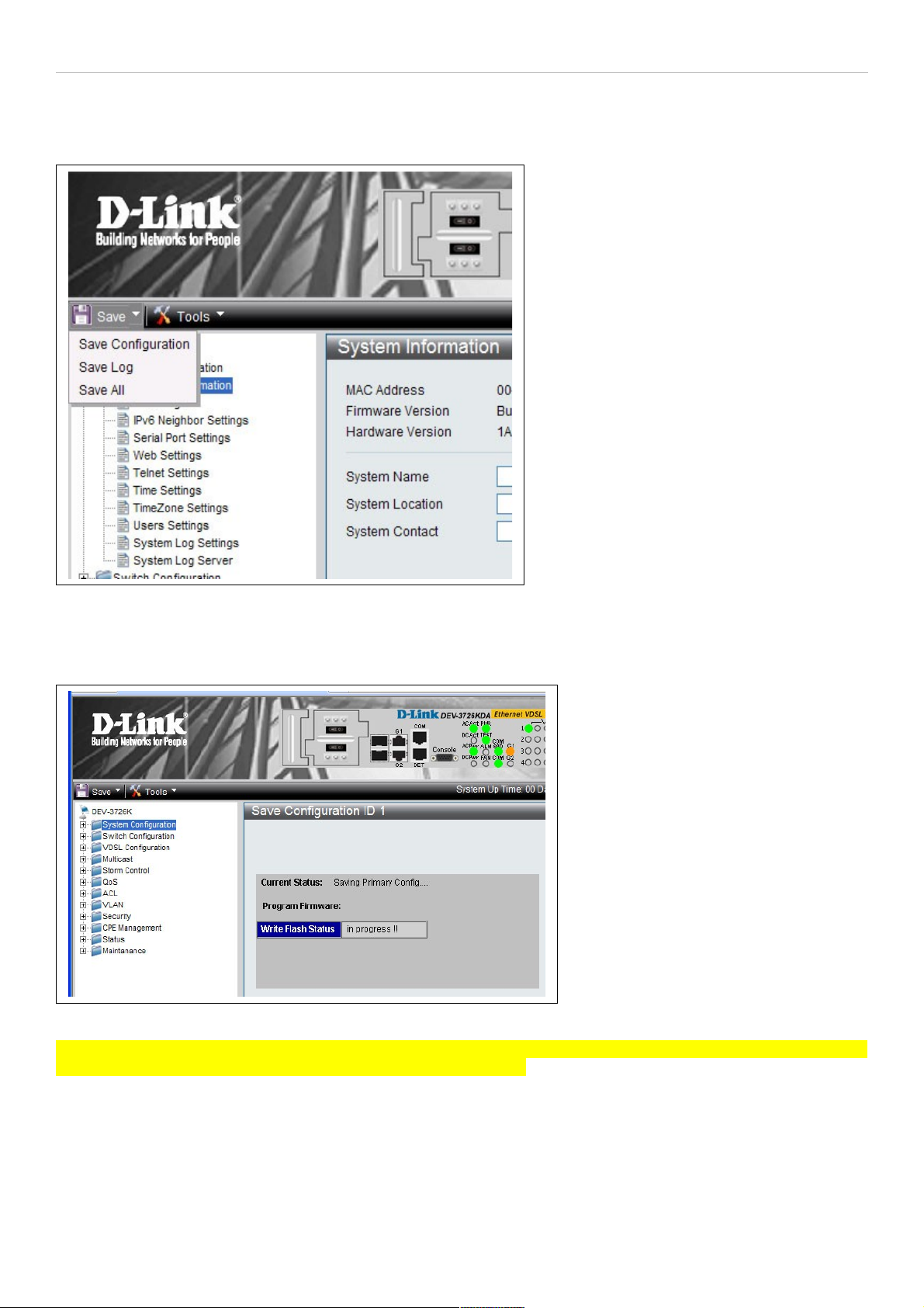
System Save Menus
The web interface for the switch includes two drop-down menus, the Save and Tools menus, located just above the
menu folders. The Save menu includes options to save switch configuration settings and switch log.
Figure 5. Save Configuration drop-down menu
To save the current configuration, from the Save drop-down menu, pull the cursor down to the Save Configuration
option. The Save Configuration menu display appears during the saving process. Upon successfully saving the
configuration, a message informs you the save is completed.
Figure 6. Save Configuration display
In addition to the Save Configuration option, the Save menus offer a Save Log and Save All option. The Save All
option saves both the System Log and the current configuration file.
10
Page 11
DAS-3626 VDSL2 Switch User Manual
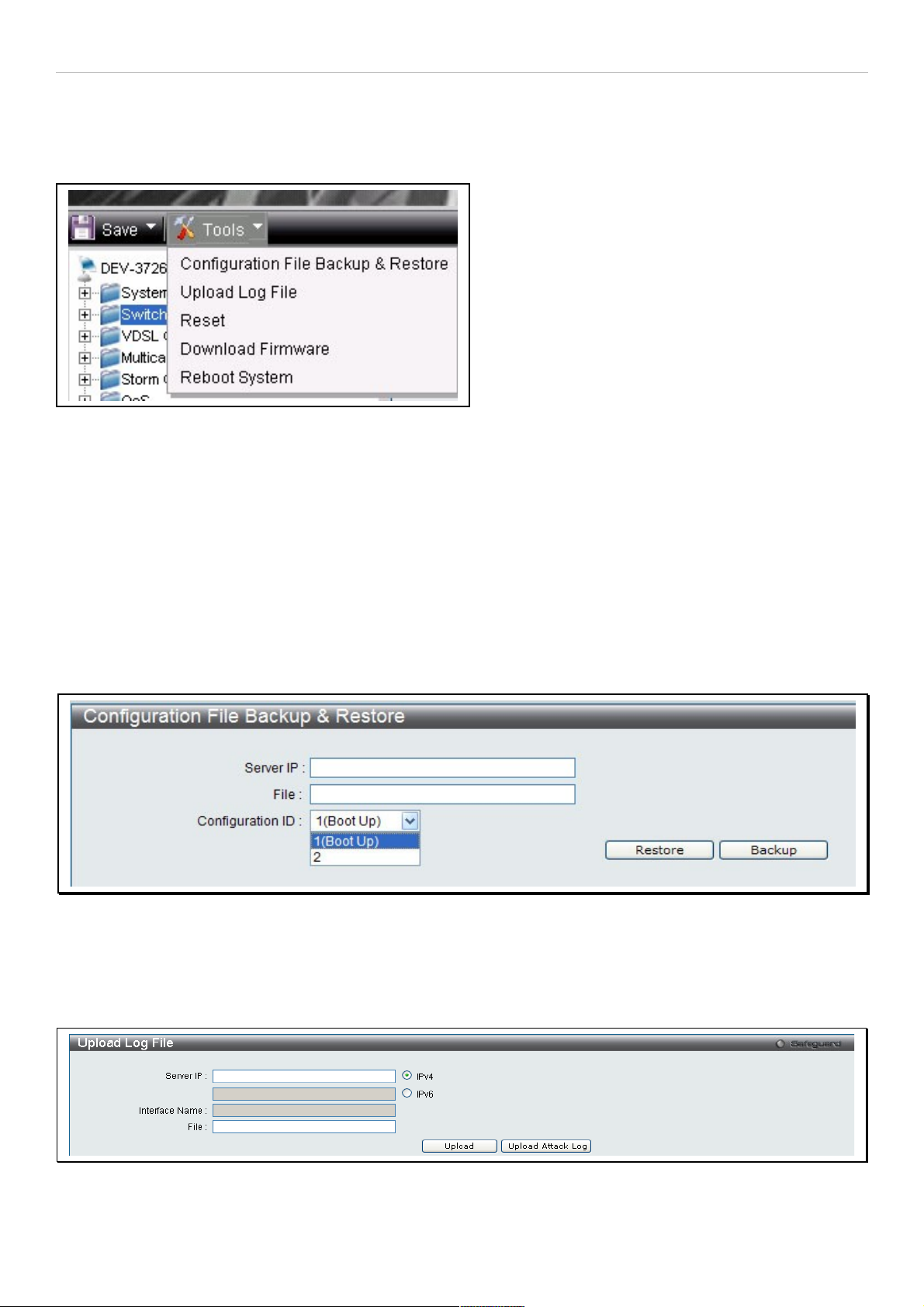
System Tools Menus
The Tools drop-down menu includes links Configuration File Backup & Restore, Upload Log File, Reset,
Download Firmware and Reboot System menus.
Figure 7. Tools drop-down menu
These menus are described below.
Configuration File Backup & Restore
The switch supports dual image storage for configuration file backup and restoration. The firmware and configuration
images are indexed by ID number 1 or 2. To change the boot firmware image, use the Configuration ID drop-down
menu to select the desired configuration file to backup or restore. The default switch settings will use image ID 1 as
the boot configuration or firmware.
To backup the configuration file, enter the Server IP (either IPv4 or IPv6), interface name, file/path name, desired
Configuration ID, and click Backup.
To restore the configuration file, enter the Server IP (either IPv4 or IPv6), interface name, file/path name, desired
Configuration ID, and click Restore.
Figure 8. Configuration File Backup & Restore menu
Upload Log File
A history and attack log can be uploaded from the switch to a TFTP server. To upload a log file, enter a Server IP
address, Interface Name and file/path name and then click Upload or Upload Attack Log.
Figure 9. Upload Log File menu
11
Page 12
DAS-3626 VDSL2 Switch User Manual
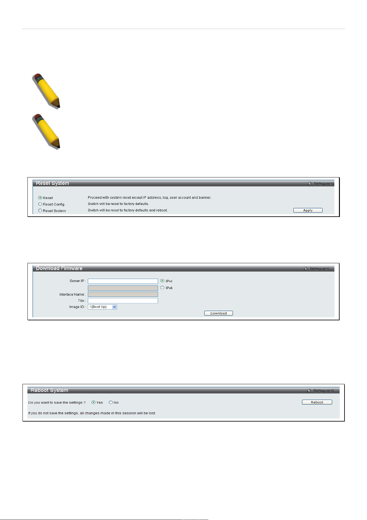
Reset
The Reset function has several options when resetting the switch. Some of the current configuration parameters can
be retained while resetting all other configuration parameters to their factory defaults.
NOTE: Only the Reset System option will enter the factory default parameters into the switch's
non-volatile RAM, and then restart the switch. All other options enter the factory defaults into the
current configuration, but do not save this configuration. Reset System will return the switch's
configuration to the state it was when it left the factory
NOTE: The serial port’s baud rate will not be changed by the reset command. It will not be restored
to the factory default setting.
Reset gives the option of retaining the switch's User Accounts and History Log while resetting all other configuration
parameters to their factory defaults. If the switch is reset using this window, and Save Changes is not executed, the
switch will return to the last saved configuration when rebooted.
Figure 10. Reset System menu
Download Firmware
The following window is used to download firmware for the switch.
Figure 11. Download Firmware menu
Enter the Server IP address, the Interface Name, the path/file name and select the desired Image ID. Click Download
to initiate the file transfer.
Reboot System
The following window is used to restart the switch.
Figure 12. Reboot System menu
Clicking the Yes radio button will instruct the switch to save the current configuration to non-volatile RAM before
restarting the switch.
Clicking the No radio button instructs the switch not to save the current configuration before restarting the switch. All of
the configuration information entered from the last time Save Changes was executed will be lost.
Click the Reboot button to restart the switch.
12
Page 13
DAS-3626 VDSL2 Switch User Manual
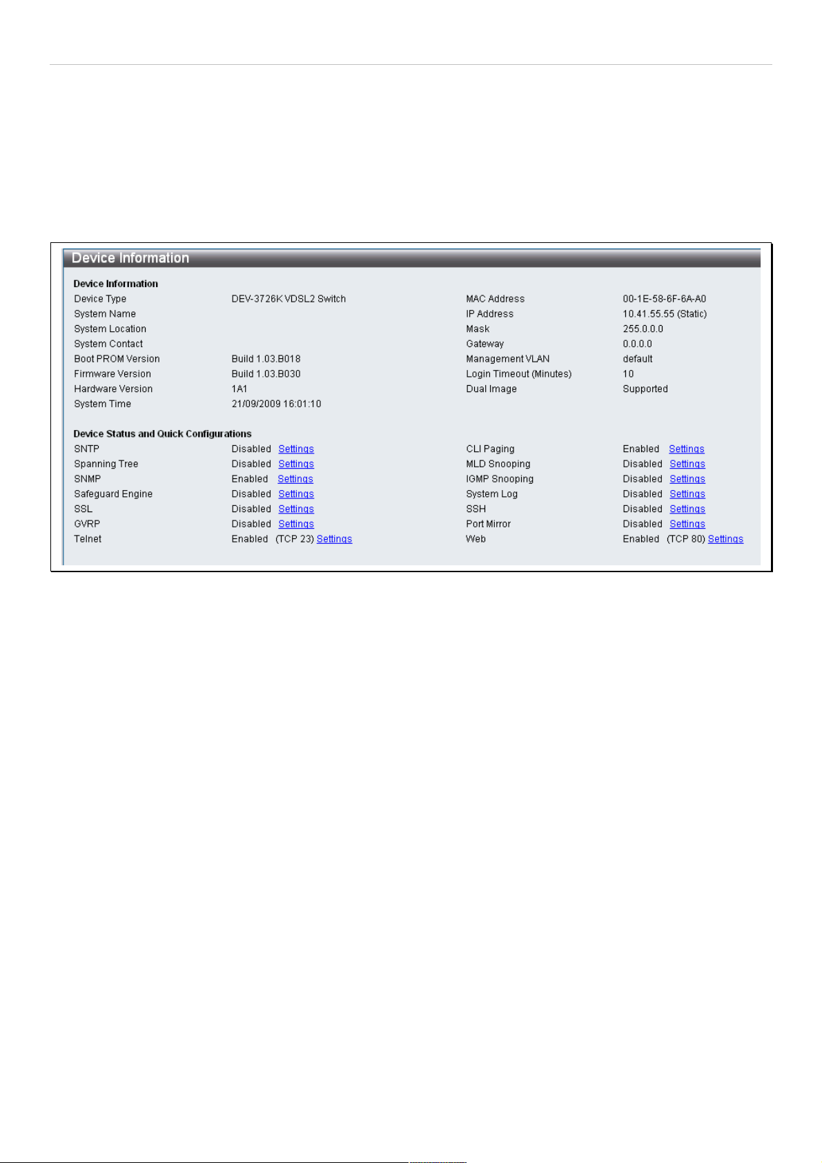
Device Information and Quick Configuration Links
This window contains the main settings for all major functions on the switch and appears automatically when you log
on. To return to the Device Information and Quick Configuration likns, click the DAS-3626 device name above the
menu folders. The Device Information display shows the switch’s MAC Address (assigned by the factory and
unchangeable), the Boot PROM Version, Firmware Version and Hardware Version as well as other information
about different settings on the switch. This information is helpful to keep track of PROM and firmware updates and to
obtain the switch's MAC address for entry into another network device's address table, if necessary. In addition, this
window displays the status of functions on the switch to quickly assess their current global status. Some functions are
hyper-linked to their configuration window for easy access from the Device Information window.
Figure 13. Device Information display and Quick Configuration links
13
Page 14

DAS-3626 VDSL2 Switch User Manual
Section 2
System Configuration
System Information
IP Settings
IPv6 Neighbor Settings
Serial Port Settings
Web Settings
Telnet Setting
Time Setting
TimeZone Setting
Users Setting
System Log Setting
System Log Server
Configuration menus in the System Configuration folder are used to change general system settings sucha as IP
settings for the two switch IP interfaces, system time settings and user account settings.This section describes the
menus contained in the System Configuration menu directory.
14
Page 15
DAS-3626 VDSL2 Switch User Manual
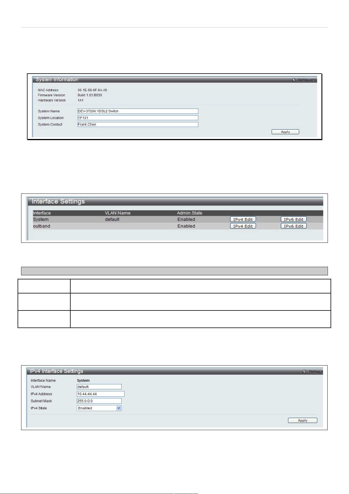
System Information
Use the System Information menu to add name, location and administrator contact information.
To view the menu, click System Configuration > System Information as shown below:
Figure 14. System Information menu
Interface Settings
The Interface Settings menu is used to access the IP settings for the two IP interefaces of the switch.
To view the menu, click System Configuration > IP Settings as shown below:
Figure 15. Interface Settings menu
The parameter values below are displayed in the Interface Settings menu:
Parameter Description
Interface The name of the IP interfaces used to manage the switch.
VLAN Name
The name of the VLAN that includes the System interface. This can be configured in the IPv4 or
IPv6 Interface Settings menu for the interface.
Admin. State
Displays the current state of the interface. Access the IPv4 or IPv6 Interface Settings menu to
enable or disable the interface.
To change the IP settings, VLAN Name, or Admin.State, click on the IPv4 Edit or IPv6 Edit button for the interface to
be configured.
In the new menu, enter the new VLAN Name, IPv4 Address and Subnet Mask, select the IPv4 State and click Apply.
To edit an entry for IPv4 features click the corresponding IPv4 Edit button.
Figure 16. IPv4 Interface Settings Edit menu
15
Page 16
DAS-3626 VDSL2 Switch User Manual
The following parameters can be configured:
Parameter Description
Interface Name Displays the interface being edited.
VLAN Name Enter the name of the VLAN corresponding to the interface. (System interface only)
IPv4 Address
Enter an alternative IPv4 address. Currently an interface can only have one IPv4 address defined.
Therefore multinetting configuration of IPv4 must be done through creation of a secondary
interface on the same VLAN, instead of directly configuring multiple IPv4 addresses on the same
interface.
Subnet Mask Enter the corresponding subnet mask.
IPv4 State This function allows user to enable the IPv4 address on the IP interface.
Click Apply to implement changes made.
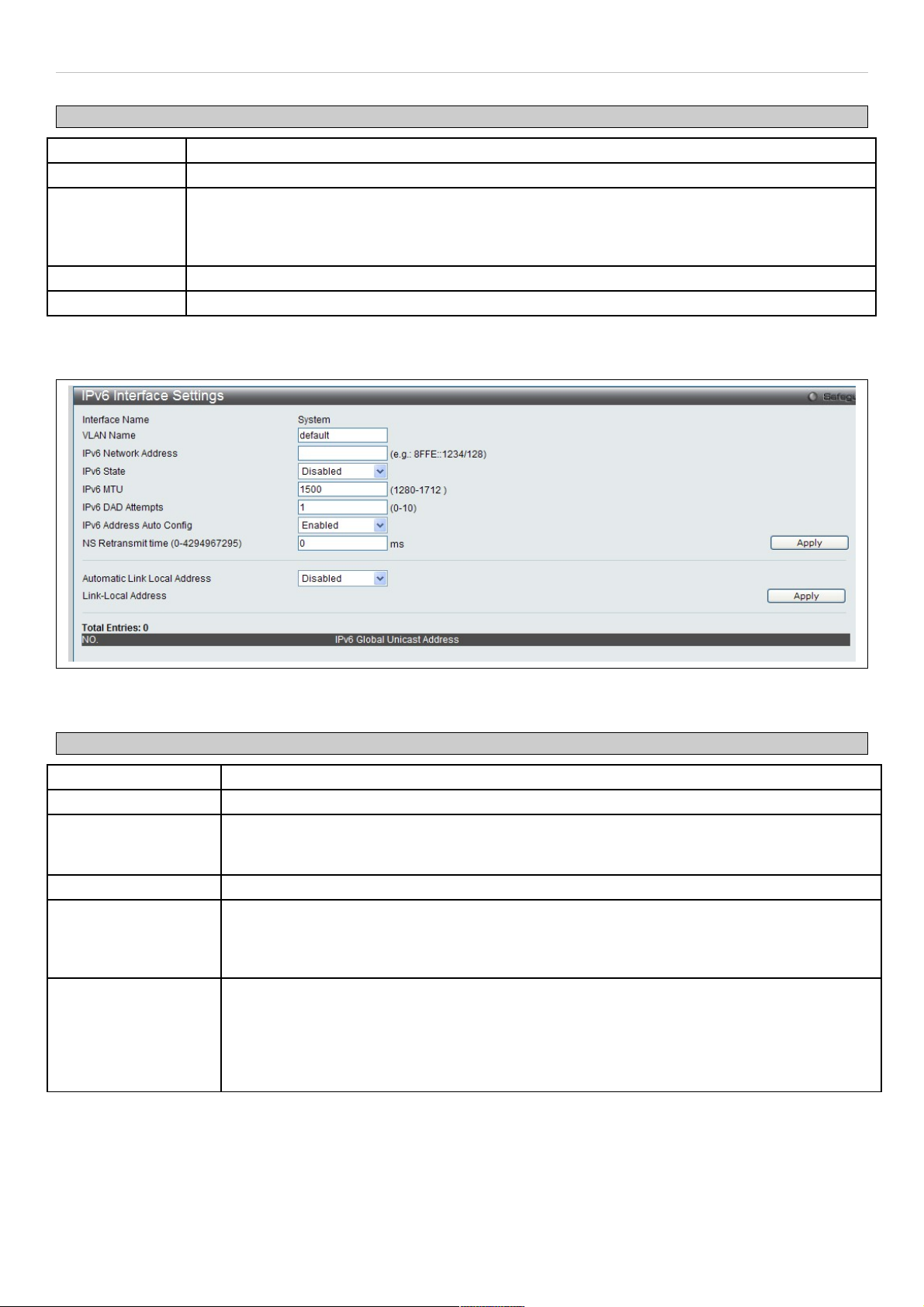
To edit an entry for IPv6 features click the corresponding IPv6 Edit button.
Figure 17. IPv6 Interface Settings Edit menu
The following parameters can be configured:
Parameter Description
Interface Name Displays the interface being edited.
VLAN Name Enter the name of the VLAN corresponding to the interface. (System interface only)
IPv6 Network
Address
Enter the IPv6 Network Address to be configured. The interface can have multiple IPv6
addresses defined. Configuration of IPv6 addresses must be done through the command
config ipif.
IPv6 State Allows the user to enable or disable the IPv6 state on the interface.
NS Retransmit time
(0-4294967295)
This field is used to set the interval, in milliseconds that the switch will produce neighbor
solicitation packets to be sent out over the local network. This is used to discover IPv6
neighbors on the local network. The user may select a time between 0 and 4294967295
milliseconds. The default is 0.
Automatic Link
Local Address
Enables or disables the automatic configuration of link local addresses when there are no
IPv6 addresses explicitly configured. When an IPv6 address is explicitly configured, the link
local address will be automatically configured, and the IPv6 processing will be started. When
there is no IPv6 address explicitly configured, by default, link local address is not configured
and the IPv6 processing will be disabled. By enabling this automatic configuration, the link
local address will be automatically configured and IPv6 processing will be started.
Click Apply to implement changes made.
16
Page 17
DAS-3626 VDSL2 Switch User Manual
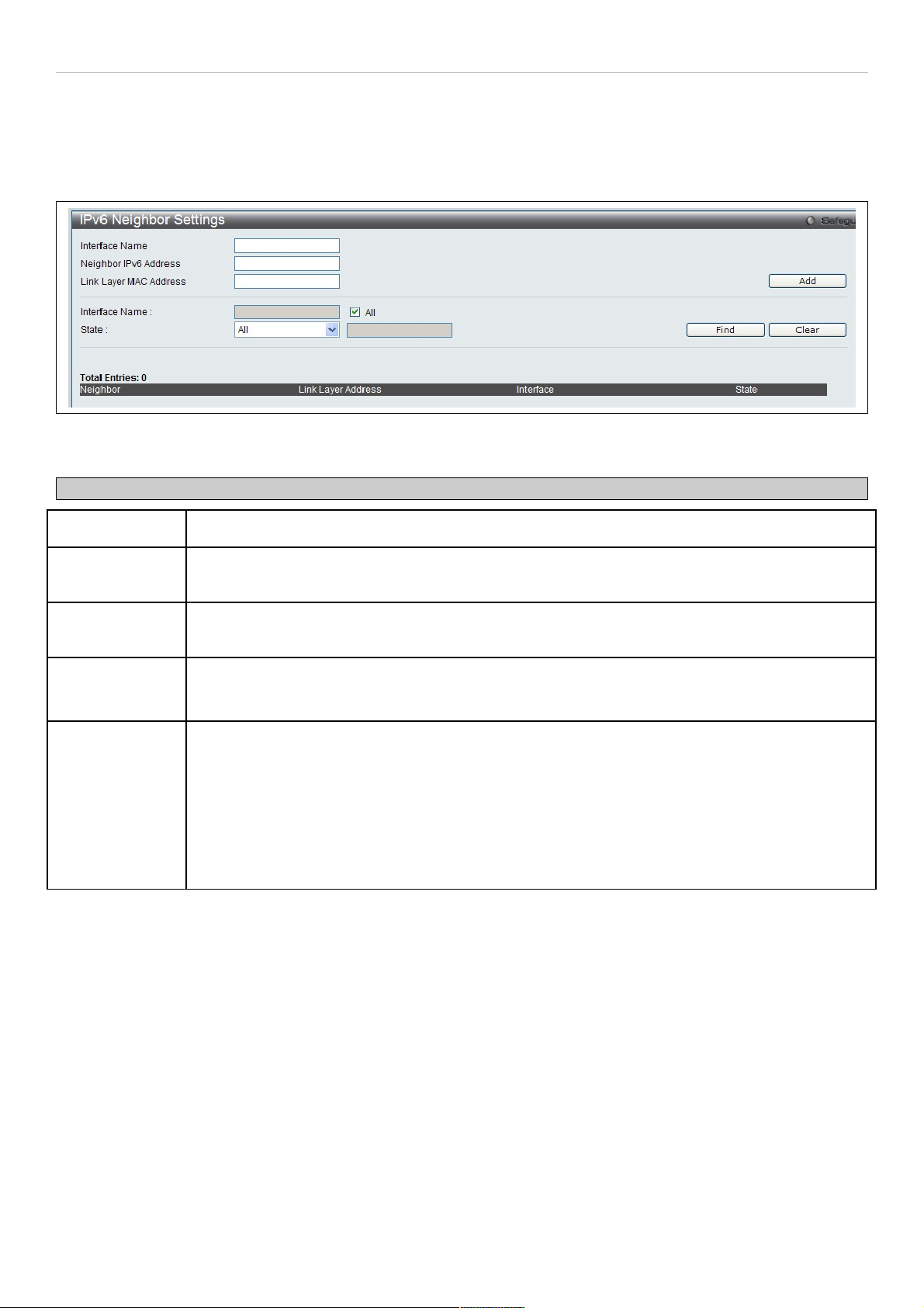
IPv6 Neighbor Settings
This window allows the user to create and configure IPv6 Neighbor settings on the switch. The switch’s current IPv6
neighbor settings will be displayed in the table at the bottom of this window.
To view this window, click System Configuration > IPv6 Neighbor Settings as shown below:
Figure 18. IPv6 Neighbor Settings menu
The following parameters can be configured:
Parameter Description
Interface Name
Enter the interface name of the IPv6 neighbor you wish to configure.
Neighbor IPv6
Address
Enter the neighbor IPv6 address of the entry you wish to configure.
Link Layer MAC
Address
Enter the MAC address of the neighbor device to be added as an IPv6 neighbor on the IP
interface.
Interface Name
In order to search for a previously configured Interface name enter the appropriate information
and click Find. To remove a previously configured Interface enter the Interface name and click
Clear.
State
To find or delete specific entries use the pull down menu to select All, Address, Static, or
Dynamic.
All – Select All to view all configured neighbor devices which are IPv6 neighbors of the IP
interface previously created.
Address – Select Address and enter the IPv6 address of the entry you wish to find.
Static – Select Static to view all statically entered IPv6 neighbors on the switch.
Dynamic – Select Dynamic to view all dynamically configured neighbor devices which are IPv6
neighbors of the IP interface previously created.
Click Add to add a new entry, click Find to search for a specific entry or click Clear to remove an entry.
17
Page 18
DAS-3626 VDSL2 Switch User Manual
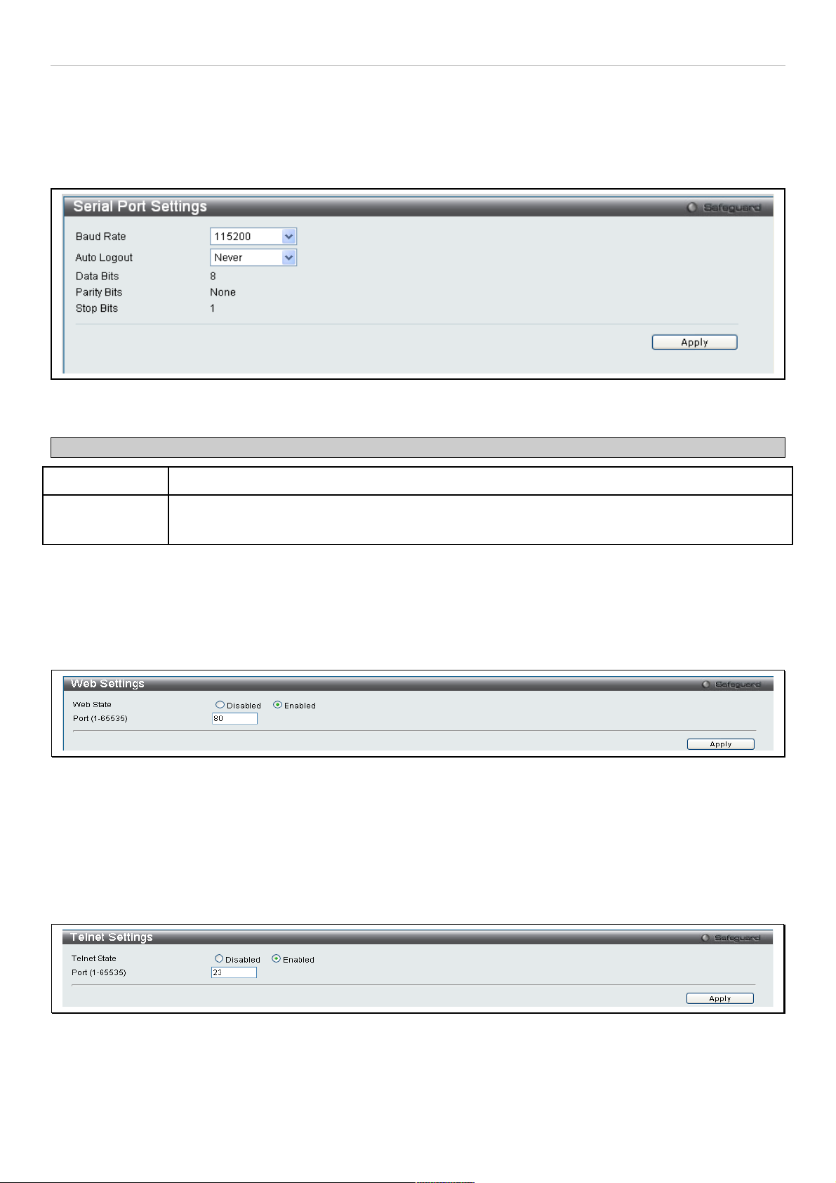
Serial Port Setting
Use the Serial Port Setting window to console serial port setting, config Baud Rate and Auto Logout setting.
To view this window, click System Configuration > Serial Port Settings as shown below:
Figure 19. Serial Port Settings
The following fields can be set:
Parameter Description
Baud Rate Select the baud rate used for the console serial port.
Auto Logout To configure console logout time, choose 2, 5, 10, 15 minutes or never logout from the pull-down
menu.
Web Settings
Web-based management is Enabled by default. If you choose to disable this by selecting Disabled, you will lose the
ability to configure the system through the web interface as soon as these settings are applied.
To view this menu, click the Web Settings link in the Quick Configuration menu as shown below:
Figure 20. Web Settings menu
Telnet Settings
Telnet configuration is Enabled by default. If you do not want to allow configuration of the system through Telnet
choose Disabled. The TCP ports are numbered between 1 and 65535. The "well-known" TCP port for the Telnet
protocol is 23.
To view this menu, click the Telnet Settings link in the Quick Configuration menu as shown below:
Figure 21. Telnet Settings menu
18
Page 19
DAS-3626 VDSL2 Switch User Manual
System Time and SNTP Settings
Simple Network Time Protocol Settings used to set system time are configured in two menus, the Time Settings and
Time Zone Settings menus.
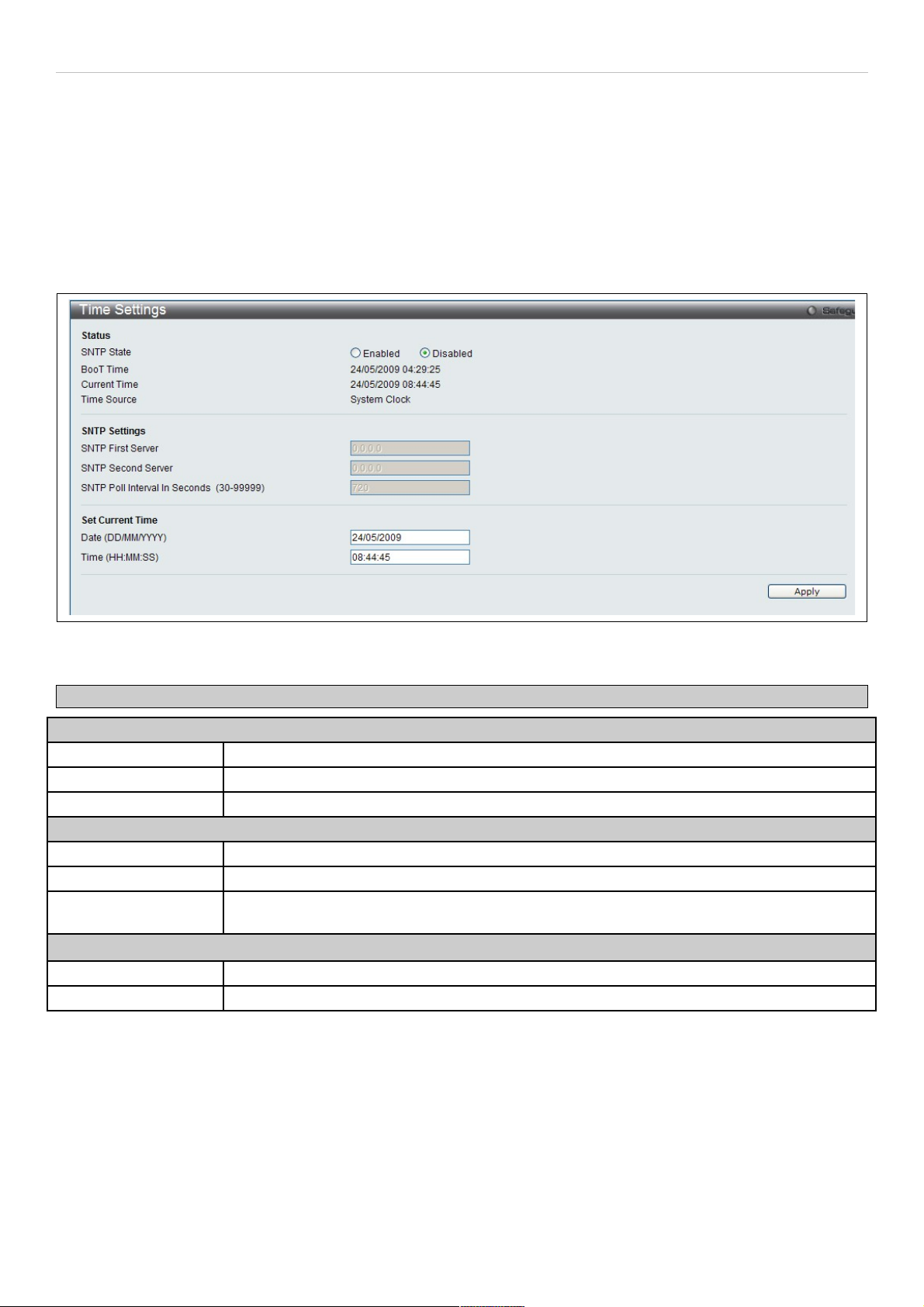
Time Settings
This window is used to configure the time settings for the switch.
To view this window, click System Configuration > Time Settings (alternatively this menu is also displayed by
clicking the SNTP Settings link in the Quick Configuration menu in the Device Information page) as shown below:
Figure 22. Time Settings menu
The following parameters can be set or are displayed:
Parameter Description
Status
SNTP State Use the radius button to select an Enabled or Disabled SNTP state.
Current Time Displays the Current Time set on the switch.
Time Source Displays the time source for the system.
SNTP Settings
SNTP First Server This is the IP address of the primary server the SNTP information will be taken from.
SNTP Second Server This is the IP address of the secondary server the SNTP information will be taken from.
SNTP Poll Interval in
Seconds (30-99999)
This is the interval, in seconds, between requests for updated SNTP information.
Set Current Time
Date (DD/MM/YYYY) Enter the current date in day, month and year to update the system clock.
Time in (HH:MM:SS) Enter the current time in hours, minutes, and seconds.
Click Apply to implement changes made.
19
Page 20
DAS-3626 VDSL2 Switch User Manual
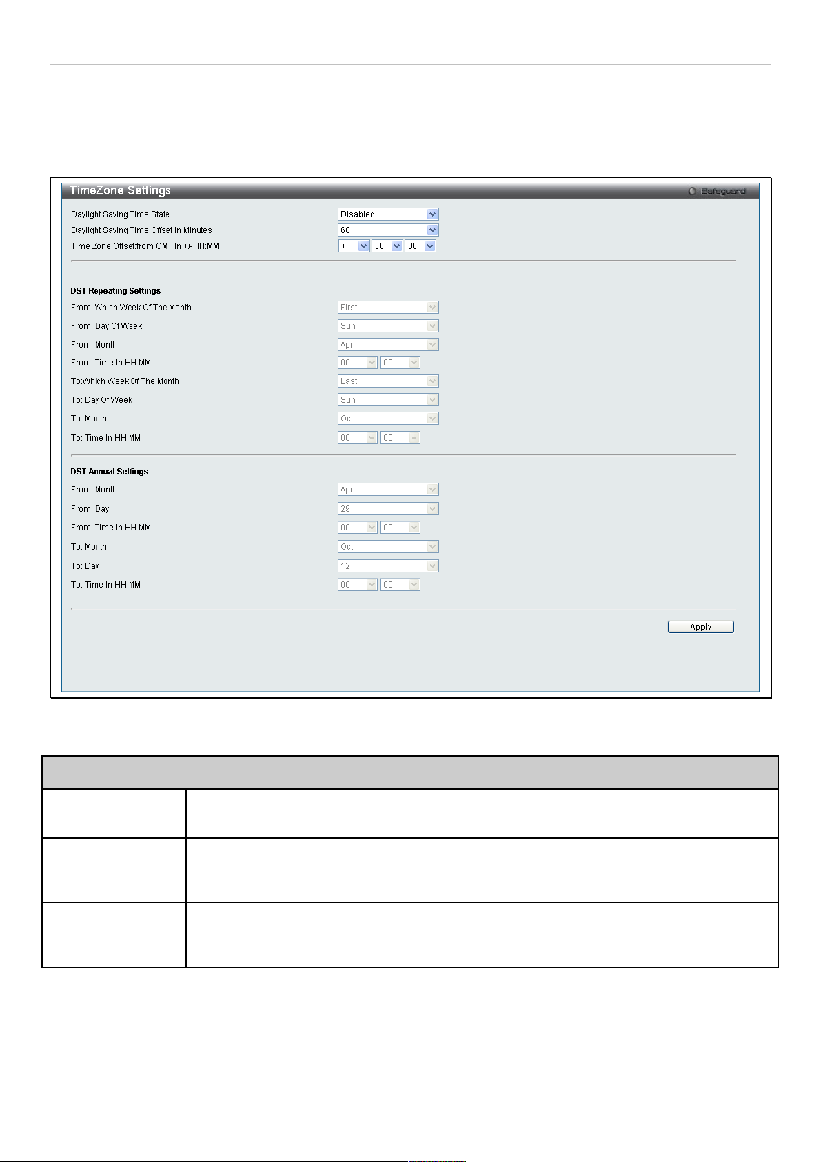
Time Zone Settings
The following window is used to configure time zones and Daylight Savings time settings for SNTP.
To view this window, click System Configuration > TimeZone Settings as shown below:
Figure 23. Time Zone and DST Settings menu
The following parameters can be set:
Time Zone and DST
Daylight Saving
Time State
Use this pull-down menu to enable or disable the DST Settings.
Daylight Saving
Time Offset in
Minutes
Use this pull-down menu to specify the amount of time that will constitute your local DST offset
30, 60, 90, or 120 minutes.
Time Zone Offset
from GMT in +/HH:MM
Use these pull-down menus to specify your local time zone's offset from Greenwich Mean
Time (GMT.)
20
Page 21
DAS-3626 VDSL2 Switch User Manual
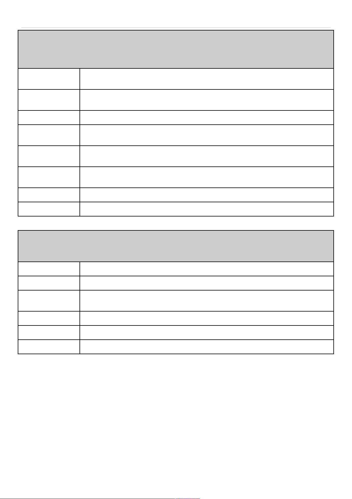
DST Repeating Settings
Using repeating mode will enable DST seasonal time adjustment. Repeating mode requires that the DST beginning
and ending date be specified using a formula. For example, specify to begin DST on Saturday during the second week
of April and end DST on Sunday during the last week of October.
From :Which Week
of the Month
Enter the week of the month that DST will start.
From: Day of the
Week
Enter the day of the week that DST will start on.
From: Month Enter the month DST will start on.
From: Time in
HH:MM
Enter the time of day that DST will start on.
To: Which Week of
the Month
Enter the week of the month the DST will end.
To: Day of the
Week
Enter the day of the week that DST will end.
To: Month Enter the month that DST will end.
To:Time in HH:MM Enter the time DST will end.
DST Annual Settings
Using annual mode will enable DST seasonal time adjustment. Annual mode requires that the DST beginning and
ending date be specified concisely. For example, specify to begin DST on April 3 and end DST on October 14.
From: Month Enter the month DST will start on, each year.
From: Day Enter the day of the week DST will start on, each year.
From: Time in
HH:MM
Enter the time of day DST will start on, each year.
To: Month Enter the month DST will end on, each year.
To: Day Enter the date DST will end on, each year.
To: Time in HH:MM Enter the time of day that DST will end on, each year.
Click Apply to implement changes made to the Time Zone and DST window.
21
Page 22
DAS-3626 VDSL2 Switch User Manual
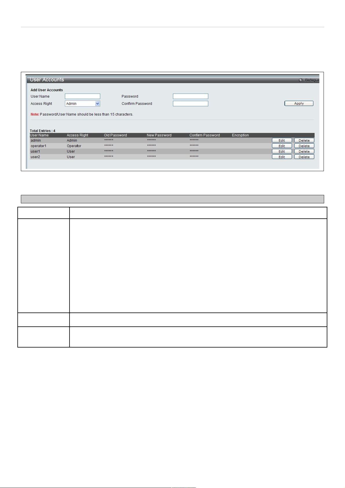
User Account Settings
The User Accounts menu is used to control user privileges, create new users and view existing User Accounts.
To view the menu, click System Configuration > User Settings:
Figure 24. User Accounts menu
The following fields can be set:
Parameter Description
User Name The name of the user, an alphanumeric string of up to 15 characters.
Access Right There are three levels of user privileges, Admin, Operator and User. Some menu selections
available to users with Admin privileges may not be available to those with User or Operator
level privileges.
There are 3 levels of security offered on the switch, the Operator level privilege will allow users to
configure and view configurations on the switch, except for those involving security features,
which are still left to the Admin level privilege. Operator level users can be authenticated through
either the local authentication method of the switch, or through the Access Authentication Control
feature, discussed later in this document. Once the user has logged in to the switch in the
Operator level, certain security screens and windows will not be made available to view, or to
configure. Only Admin level users have access to these features.
(Ошибка: источник перекрестной ссылки не найден below summarizes Admin, Operator and
User level privileges)
New Password Enter a password for the new user.
Confirm New
Password
Retype the new password.
To add a new user, enter the appropriate information and click Apply. To delete an account click the corresponding
Delete button. To modify an existing user account, click Edit as shown below.
22
Page 23
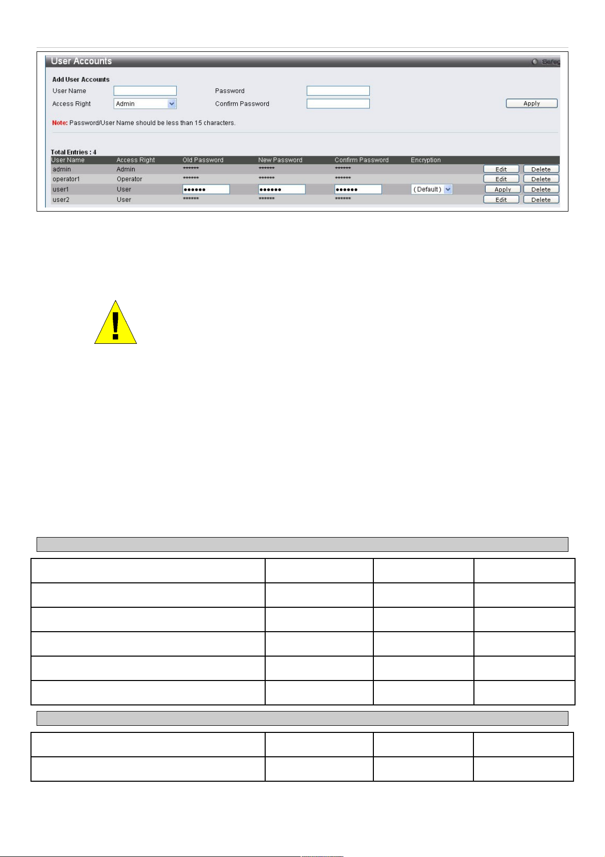
DAS-3626 VDSL2 Switch User Manual
Figure 25. User Accounts menu
Enter the Old Password for the account, the New Password you wish to use, and retype the new password in the
Confirm Password field. Use the drop-down menu to select the type of encryption (Default, Plain Text or Sha 1), and
click Apply.
NOTICE: In case of lost passwords or password corruption, please refer to the
D-Link website and the White Paper entitled “Password Recovery Procedure”,
which will guide you through the steps necessary to resolve this issue.
Admin, Operator and User Privileges
Recently added to the levels of security offered on the switch, the Operator level privilege will allow users to configure
and view configurations on the switch, except for those involving security features, which are still left to the Admin
privilege. Operator users can be authenticated through either the local authentication method of the switch, or through
the Access Authentication Control feature, discussed later in this document. Once the user has logged in to the switch
in the Operator level, certain security screens and windows will not be made available to view, or to configure. Only
Admin level users have access to these features.
There are three levels of user privileges, Admin, Operator and User. Some menu selections available to users with
Admin privileges may not be available to those with User or Operator privileges.
The following table summarizes the Admin, Operator and User privileges:
Management Admin Operator User
Configuration Yes Yes Read-only
Network Monitoring Yes Yes Read-only
Community Strings and Trap Stations Yes Yes Read-only
Update Firmware and Configuration Files Yes No No
System Utilities Yes Yes No
Factory Reset Yes No No
User Account Management
Add/Update/Delete User Accounts Yes No No
View User Accounts Yes No No
Figure 26. Admin, Operator and User Privileges
23
Page 24
DAS-3626 VDSL2 Switch User Manual
System Log Configuration
This section contains information for configuring various attributes and properties for System Log Configurations,
including System Log Settings and System Log Host.
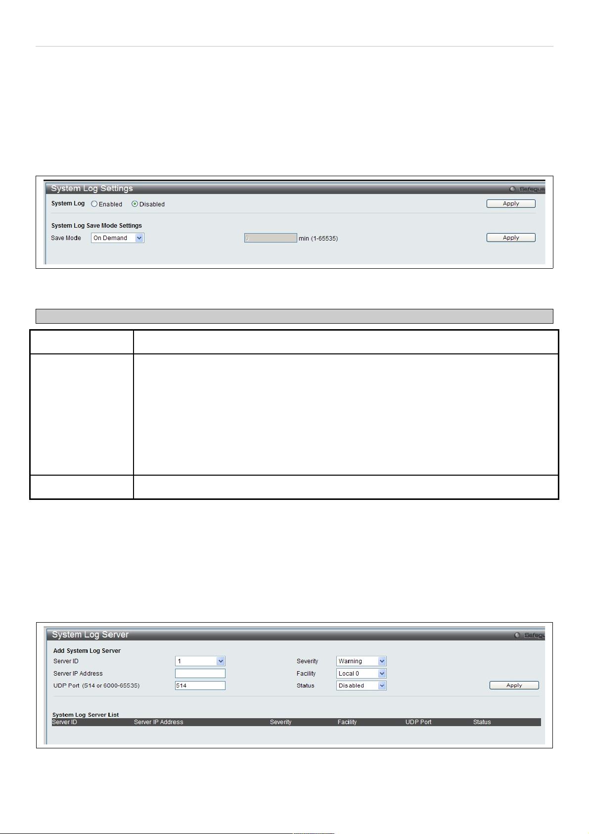
System Log Settings
This window allows the user to enable or disable the System Log and specify the System Log Save Mode Settings.
To view this window, click System Configuration > System Log Settings as shown below:
Figure 27. System Log Settings menu
The following parameters can be set:
Parameter Description
System Log To activate the System Log select Enabled or Disabled.
Save Mode Use this drop-down menu to specify the method that will trigger a log entry. You can choose
between On Demand, Time Interval and Log Trigger.
On Demand – This method will only save log files when they manually tell the switch to do so,
using the Save Log link in the Save folder.
Time Interval – This method configures a time interval by which the switch will save the log
files. The user may set a time between 1 and 65535 minutes.
Log Trigger – This method will save log files to the switch every time a log event occurs on the
switch.
Minutes (1-65535) Enter a time interval, in minutes, for which you would like a log entry to be made.
To add a new entry, enter the appropriate information and click Apply.
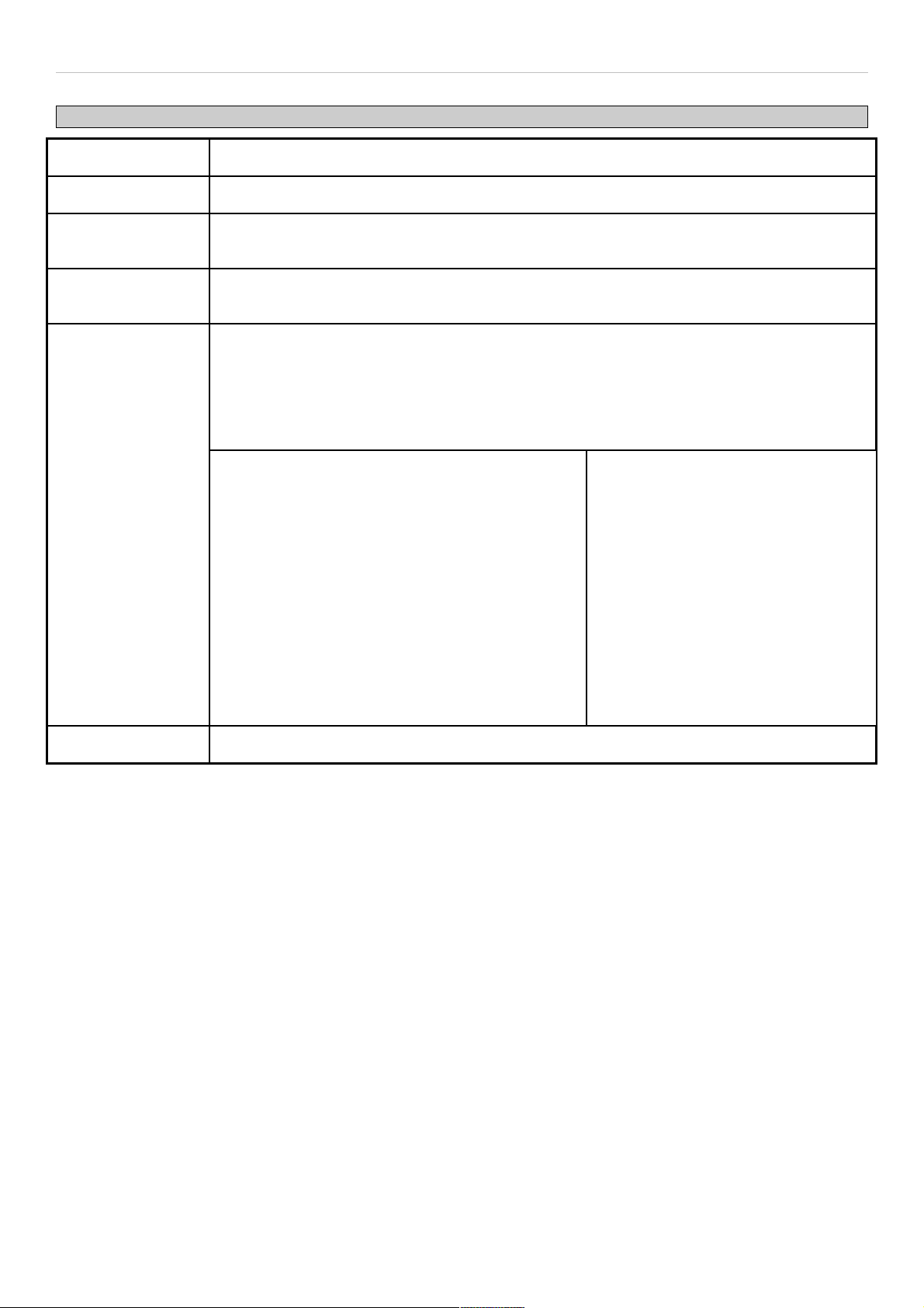
System Log Server
The switch can send Syslog messages to up to four designated servers using the System Log Server.
To view this window, click System Configuration > System Log Configuration > System Log Server as shown
below:
Figure 28. System Log Server menu
24
Page 25
DAS-3626 VDSL2 Switch User Manual
The following parameters can be set:
Parameter Description
Server ID Syslog server settings index (1-4).
Server IP Address The IP address of the Syslog server.
UDP Port
(514 or 6000-65535)
Type the UDP port number used for sending Syslog messages. The default is 514.
Severity This drop-down menu allows you to select the level of messages that will be sent. The options
are Warning, Informational, and All.
Facility Some of the operating system daemons and processes have been assigned Facility values.
Processes and daemons that have not been explicitly assigned a Facility may use any of the
"local use" facilities or they may use the "user-level" Facility. Those Facilities that have been
designated are shown in the following: Bold font indicates the facility values that the switch is
currently employing.
Numerical Facility Code Numerical Facility Code
0
1
2
3
4
5
7
8
9
10
11
kernel messages
user-level messages
mail system
system daemons
security/authorization messages
messages generated internally by
syslog line printer subsystem
network news subsystem
UUCP subsystem
clock daemon
security/authorization messages
FTP daemon
12
13
14
15
16
17
18
19
20
21
22
23
NTP subsystem
log audit
log alert
clock daemon
local use 0 (local0)
local use 1 (local1)
local use 2 (local2)
local use 3 (local3)
local use 4 (local4)
local use 5 (local5)
local use 6 (local6)
local use 7 (local7)
Status Choose Enabled or Disabled to activate or deactivate.
25
Page 26

DAS-3626 VDSL2 Switch User Manual
Section 3
Switch Configuration
MAC Address Aging Time
Ethernet Settings
FDB
Traffic Segmentation
CLI Paging
Port Mirror
LACP Port Settings
Loopback Detection Settings
QinQ Settings
GVRP
DHCP/BOOTP Relay Settings
Spanning Tree Settings
Multiple Spanning Tree Settings
CFM
The Switch Configurtion Section includes these functions discussed in detail.
26
Page 27
DAS-3626 VDSL2 Switch User Manual
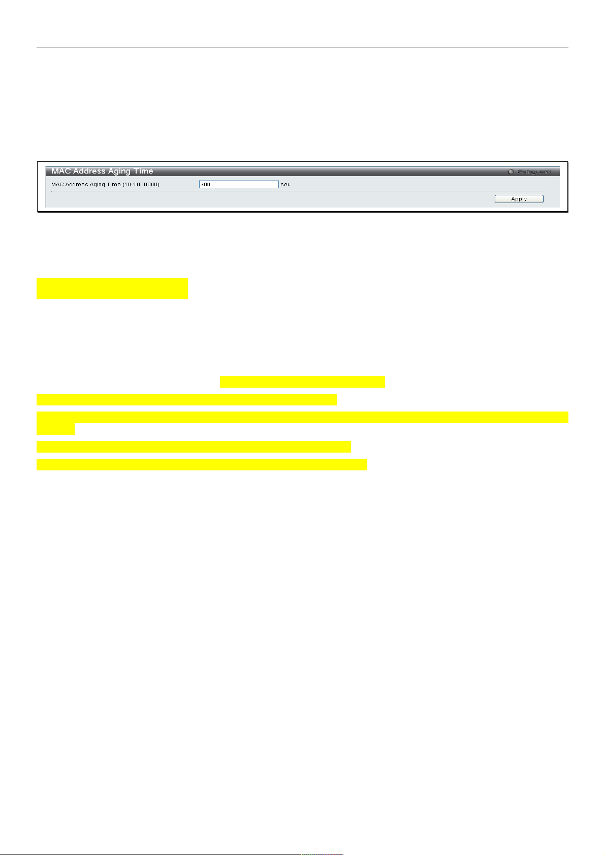
MAC Address Aging Time
This table specifies the length of time a learned MAC Address will remain in the forwarding table without being
accessed (that is, how long a learned MAC Address is allowed to remain idle). To change this, enter a value
representing the MAC address age-out time in seconds. The MAC Address Aging Time can be set to any value
between 10 and 1,000,000 seconds. The default setting is 300 seconds.
To view this window, click Switch Configuration > MAC Address Aging Time as shown below:
Figure 29. MAC Address Aging Time menu
Ethernet Settings
Figure 30. (Ethernet) Port Settings
Users may configure the speed and duplex of Ethernet port 1 here.
Auto negotiate – Turning on this feature will automatically adjust the speed and duplex of this port to its optimum
settings.
Speed – Users may set the port speed here, as 10, 100 or 1000Mbps.
Duplex – Users may set the duplex settings for the port her, as half or full.
27
Page 28
DAS-3626 VDSL2 Switch User Manual
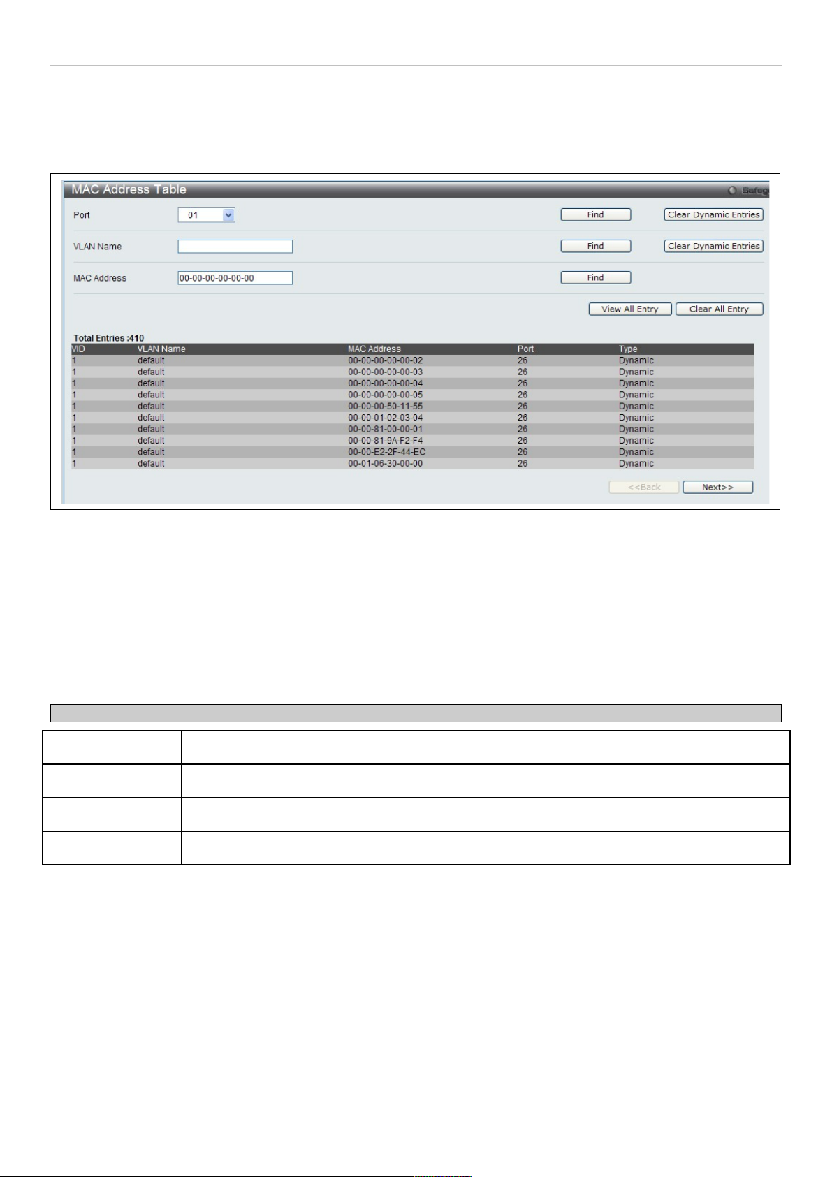
FDB
Use the MAC Address Table menu to view or clear entries from the switch's MAC address forwarding data base (FDB)
To view this menu, click Switch Configuration > FDB as shown below:
Figure 31. Forwarding Database entry table
Search options include searching by Port number, VLAN Name or specific MAC Address. To search the FDB, select
the entry menu for the type of search to conduct (Port, VLAN Name or MAC Address), enter or select the port, VLAN
name or MAC address, and click on the Find button.
To scroll through the FDB list manually, click on the Next and Back buttons.
To clear FDB entries choose to clear dynamic entries for a specified Port or VLAN by clicking on the Clear Dynamic
Entries button for the search option used. Alternatively, to clear all entries in the FDB, click on the Clear All Entries
button.
The MAC Address Table lists the following information:
Parameter Description
VID The VID of the VLAN from which packets are forwarded.
Port The corresponding VDSL line of which the VID is a member.
MAC Address The MAC address that resides on the port where traffic is forwarded.
Type The type of FDB entry, Dynamic or Static.
28
Page 29
DAS-3626 VDSL2 Switch User Manual
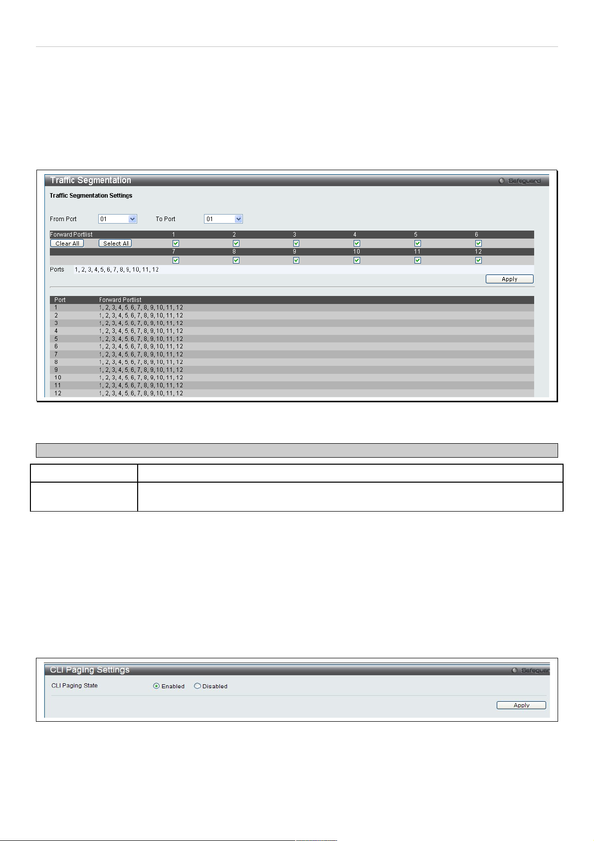
Traffic Segmentation
Traffic segmentation is used to limit traffic flow from a single port to a group of ports on either a single switch or a
group of ports on another switch in a switch stack. This method of segmenting the flow of traffic is similar to using
VLANs to limit traffic, but is more restrictive. It provides a method of directing traffic that does not increase the
overhead of the Master switch CPU. This page allows you to view which port on a given switch will be allowed to
forward packets to other ports on that switch. Select a port number from the drop down menu to display the forwarding
ports. To configure new forwarding ports for a particular port, select a port from the menu and click Apply.
To view this window, click Switch Configuration > Traffic Segmentation as shown below:
Figure 32. Traffic Segmentation menu
The following fields can be set
Parameter Description
From Port / To Port Check the corresponding boxes for the port(s) to transmit packets.
Forward Portlist Check the boxes to select which of the ports on the switch will be able to forward packets.
These ports will be allowed to receive packets from the port specified above.
Clicking the Apply button will enter the combination of transmitting port and allowed receiving ports into the switch's
Current Traffic Segmentation Table.
CLI Paging Settings
Clipaging Status can be Enabled or Disabled in this window, it is Enabled by default. Clipaging settings are used when
issuing a command which causes the console screen to rapidly scroll through several pages. This command will cause
the console to pause at the end of each page.
To view this menu, click the CLI Paging link in the Quick Configuration menu as shown below:
Figure 33. CLI Paging Settings menu
29
Page 30
DAS-3626 VDSL2 Switch User Manual
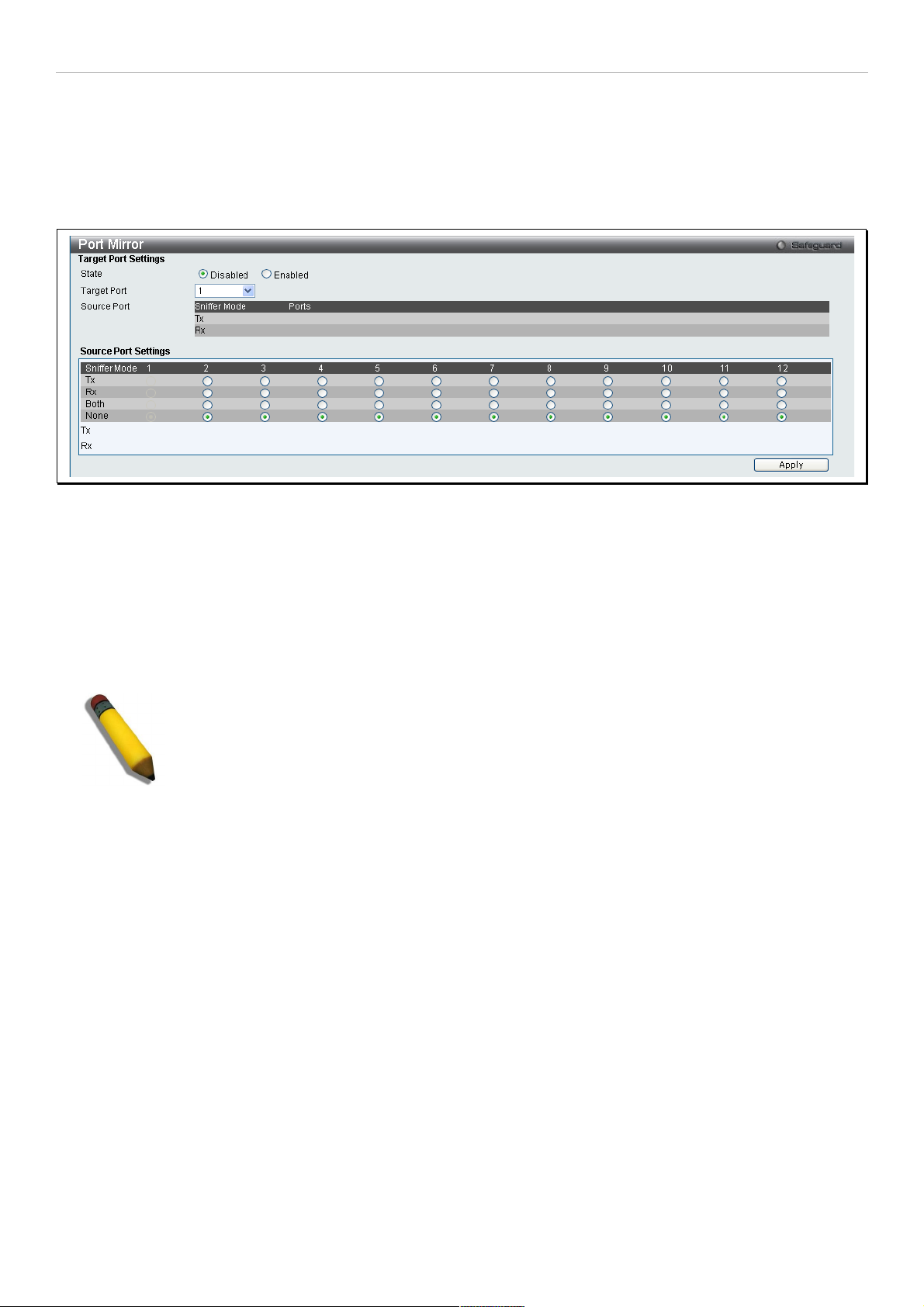
Port Mirror
The switch allows you to copy frames transmitted and received on a port and redirect the copies to another port. You
can attach a monitoring device to the mirrored port, such as a sniffer or an RMON probe, to view details about the
packets passing through the first port. This is useful for network monitoring and troubleshooting purposes.
To view this window, click Switch Configuration > Port Mirror as shown below:
Figure 34. Port Mirror menu
To configure a mirror port:
1. Change the status to Enabled.
2. Select the Source Port from where you want to the frames to come from.
3. Select the Target Port, which receives the copies from the source port.
4. Click Apply to let the changes take effect.
NOTE: You cannot mirror a fast port onto a slower port. For example, if you try to mirror the
traffic from a 100 Mbps port onto a 10 Mbps port, this can cause throughput problems. The port
you are copying frames from should always support an equal or lower speed than the port to
which you are sending the copies. Also, the target port for the mirroring cannot be a member of
a trunk group. Please note a target port and a source port cannot be the same port.
30
Page 31

DAS-3626 VDSL2 Switch User Manual
Port Trunking
Understanding Port Trunk Groups
Port trunk groups are used to combine a number of ports together to make a single high-bandwidth data pipeline. The
DAS-3626 supports single trunk group for the two Gigabit Ethernet (ports Ports 25 and 26). A potential bit rate of 2000
Mbps can be achieved.
The switch treats both ports in the trunk group as a single port. Data transmitted to a specific host (destination
address) will always be transmitted over the same port in a trunk group. This allows packets in a data stream to arrive
in the same order they were sent.
NOTE: If either port within the trunk group becomes disconnected, packets intended for the
disconnected port are load shared among the other unlinked ports of the link aggregation
group.
Link aggregation is supported for the Gigabit Ethernet ports only. Both ports in the group must be members of the
same VLAN, and their STP status, static multicast, traffic control; traffic segmentation and 802.1p default priority
configurations must be identical. Port locking, port mirroring and 802.1X must not be enabled on the trunk group.
Further, the aggregated links must all be of the same speed and should be configured as full duplex.
The Master Port of the group is to be configured by the user, and all configuration options, including the VLAN
configuration that can be applied to the Master Port, are applied to the entire link aggregation group.
Load balancing is automatically applied to the ports in the aggregated group, and a link failure within the group causes
the network traffic to be directed to the remaining links in the group.
The Spanning Tree Protocol will treat a link aggregation group as a single link, on the switch level. On the port level,
the STP will use the port parameters of the Master Port in the calculation of port cost and in determining the state of
the link aggregation group. If two redundant link aggregation groups are configured on the switch, STP will block one
entire group; in the same way STP will block a single port that has a redundant link.
To view this window, click Switch Configuraiton > Port Trunking as shown below:
Figure 35. Port Trunking menu
To create a port trunk with Gigabit Ethernet ports 25 and 26, click to checkmark the boxes 25 and 26, configure the
menu options and click the Apply button.
31
Page 32

DAS-3626 VDSL2 Switch User Manual
Configurable options and and display information in the Port Trunking menu include the following:
Parameter Description
Algorithm The algorithm that the switch uses to balance the load across the ports that make up the port
trunk group is defined by this definition. Choose MAC Source, MAC Destination, MAC Source
Dest, IP Source, IP Destination or IP Source Dest (See the Link Aggregation section of this
manual).
Group ID Select an ID number for the group.
Type This pull-down menu allows you to select between Static and LACP (Link Aggregation Control
Protocol). LACP allows for the automatic detection of links in a Port Trunking Group.
Master Port Choose the Master Port for the trunk group using the pull-down menu.
State Toggle Enabled and Disabled to enable or disable the port trunk. This is useful for diagnostics,
to quickly isolate a bandwidth intensive network device or to have an absolute backup
aggregation group that is not under automatic control.
Click Apply to implement changes made.
LACP Port Settings
The LACP Port Settings window is used to create port trunking groups on the switch. Using the following window, the
user may set which ports will be active and passive in processing and sending LACP control frames.
To view this window, click Switch Configuration > LACP Port Settings as shown below:
Figure 36. LACP Port Settings menu
The following fields can be set
Parameter Description
From Port / To Port Ports 25 and 26 are the only ports on the DAS-3626 available for LACP.
Activity
Active – Active LACP ports are capable of processing and sending LACP control frames. This
allows LACP compliant devices to negotiate the aggregated link so the group may be
changed dynamically as needs require. In order to utilize the ability to change an aggregated
port group, that is, to add or subtract ports from the group, at least one of the participating
devices must designate LACP ports as active. Both devices must support LACP.
Passive – LACP ports that are designated as passive cannot initially send LACP control
frames. In order to allow the linked port group to negotiate adjustments and make changes
dynamically, one end of the connection must have "active" LACP ports (see above).
Click Apply to implement changes made.
32
Page 33

DAS-3626 VDSL2 Switch User Manual
Loopback Detection Settings
The Loopback Detection function is used to detect the loop created by a specific port. This feature is used to
temporarily shutdown a port on the Switch when a loop detecting packet has been looped back to the switch. When
the Switch detects that these packets are received from a port or a VLAN, it signifies a loop on the network. The
Switch will automatically block the port or the VLAN and send an alert to the administrator. The Loopback Detection
port will restart (change to discarding state) when the Loopback Detection Recover Time times out. The Loopback
Detection function can be implemented on a range of ports at a time. The user may enable or disable this function
using the pull-down menu.
To view this window, click Switch Configuration > Loopback Detection Settings as shown below:
Figure 37. Loopback Detection Settings menu
The following parameters can be configured:
Parameter Description
LBD State Used to Enable or Disable loopback detection. The default is Disabled.
Mode Use the drop-down menu to toggle between Port Based and VLAN Based.
Interval (1-32767) Set a Loopdetect Interval between 1 and 32767 seconds. The default is 10 seconds.
Trap Status Select the trap status, choose None, Loop Detected, Loop Cleared or Both.
Recover Time
(0 or 60-1000000)
Time allowed (in seconds) for recovery when a Loopback is detected. The Loopdetect
Recover Time can be set at 0 seconds, or 60 to 1000000 seconds. Entering 0 will disable the
Loopdetect Recover Time. The default is 60 seconds.
From Port / To Port Use the drop-down menu to select a beginning and ending port number.
State Use the drop-down menu to toggle between Enabled and Disabled.
Click Apply to implement changes made.
33
Page 34

DAS-3626 VDSL2 Switch User Manual
Q-in-Q Settings
This function allows the user to enable or disable the Q-in-Q function. Q-in-Q is designed for service providers to carry
traffic from multiple users across a network. Q-in-Q is used to maintain customer specific VLAN and Layer 2 protocol
configurations even when the same VLAN ID is being used by different customers. This is achieved by inserting
SPVLAN tags into the customer’s frames when they enter the service provider’s network, and then removing the tags
when the frames leave the network.
Customers of a service provider may have different or specific requirements regarding their internal VLAN IDs and the
number of VLANs that can be supported. Therefore customers in the same service provider network may have VLAN
ranges that overlap, which might cause traffic to become mixed up. So assigning a unique range of VLAN IDs to each
customer might cause restrictions on some of their configurations requiring intense processing of VLAN mapping
tables which may exceed the VLAN mapping limit. Q-in-Q uses a single service provider VLAN (SPVLAN) for
customers who have multiple VLANs. Customer’s VLAN IDs are segregated within the service provider’s network
even when they use the same customer specific VLAN ID. Q-in-Q expands the VLAN space available while preserving
the customer’s original tagged packets and adding SPVLAN tags to each new frame.
To view this window, click Switch Configuration > QinQ as shown below:
Figure 38. QinQ Settings menu
The following fields can be set:
Parameter Description
From Port / To Port A consecutive group of ports that are part of the VLAN configuration starting with the selected
port.
Role The user can choose between UNI or NNI role.
UNI – To select a user-network interface which specifies that communication between the
specified user and a specified network will occur.
NNI – To select a network-to-network interface specifies that communication between two
specified networks will occur.
Missdrop Use the drop down menu to enable or disable missdrop. If missdrop is enabled, the packet
that does not match any assignment rule in the Q-in-Q profile will be dropped. If disabled, then
the packet will be assigned to the PVID of the receiving port.
Outer TPID The Outer TPID is used for learning and switching packets.
Use Inner Priority The priority given to the inner tag will be copied to the outer tag if this setting is enabled.
Add Inner Tag(hex:
0x1-0xffff)
Specify whether to add inner tag for ingress untagged packets. If set, the inner tag will be
added for the ingress untagged packets and thus the packets egress to the NNI port will be
double tagged.
Click Apply to implement changes.
34
Page 35

DAS-3626 VDSL2 Switch User Manual
GVRP Global Settings
The GVRP allows interoperability with other switches, so the values of the GVRP timers can be configured. This table
is used to set the GVRP Global Settings.
To view this window, click Switch Configuration > GVRP Global Settings as shown below:
Figure 39. GVRP Global Settings menu
The following fields can be set:
Parameter Description
Join Time
(100-100000)
The time in milliseconds that specifies the amount of time between the Switch receiving the
information about becoming a member of the group and actually joining the group. The default
is 200.
Leave Time
(100-100000)
The time in milliseconds that specifies the maximum amount of time between the Switch
receiving a leave group message from a host, and the Switch issuing a group membership
query. The default is 600. The Leave Time must be greater than 2 join times.
Leave All Time
(100-100000)
The time in milliseconds that specifies the amount of time the Switch will take to Leave All
groups. The default is 10000. The Leave All Time must be greater than the Leave Time.
NNI BPDU
Address
This specifies the GVRP’s pdu MAC address of the NNI port.
Dot1d – Specifies GVRP’s pdu MAC address of NNI port using 802.1d.
Dot1ad – Specifies GVRP’s pdu MAC address of NNI port using 802.1ad.
Click Apply to implement changes made.
GVRP Settings
The table allows the user to determine whether the Switch will share its VLAN configuration information with other
GARP VLAN Registration Protocol (GVRP) enabled switches. In addition, Ingress Checking can be used to limit traffic
by filtering incoming packets whose PVID do not match the PVID of the port. Results can be seen in the table under
the configuration settings, as seen below.
To view this window, click Switch Configuration > GVRP Settings as shown below:
35
Page 36

DAS-3626 VDSL2 Switch User Manual
Figure 40. GVRP Settings menu
The following fields can be set:
Parameter Description
From Port / To Port These two fields allow you to specify the range of ports that will be included in the Port-based
VLAN that you are creating using the 802.1Q Port Settings window.
GVRP The Group VLAN Registration Protocol (GVRP) enables the port to dynamically become a
member of a VLAN. GVRP is Disabled by default.
PVID The read-only field in the 802.1Q Port Table shows the current PVID assignment for each
port, which may be manually assigned to a VLAN when created in the 802.1Q Port Settings
table. The Switch's default is to assign all ports to the default VLAN with a VID of 1. The PVID
is used by the port to tag outgoing, untagged packets, and to make filtering decisions about
incoming packets. If the port is specified to accept only tagged frames - as tagging, and an
untagged packet is forwarded to the port for transmission, the port will add an 802.1Q tag
using the PVID to write the VID in the tag. When the packet arrives at its destination, the
receiving device will use the PVID to make VLAN forwarding decisions. If the port receives a
packet, and Ingress filtering is enabled, the port will compare the VID of the incoming packet
to its PVID. If the two are unequal, the port will drop the packet. If the two are equal, the port
will receive the packet.
Ingress Checking This field can be toggled using the space bar between Enabled and Disabled. Enabled
enables the port to compare the VID tag of an incoming packet with the PVID number
assigned to the port. If the two are different, the port filters (drops) the packet. Disabled
disables ingress filtering. Ingress Checking is Disabled by default.
Acceptable Frame
Type
This field denotes the type of frame that will be accepted by the port. The user may choose
between Tagged Only, which means only VLAN tagged frames will be accepted, and
Admit_All, which mean both tagged and untagged frames will be accepted. Admit_All is
enabled by default.
Click Apply to implement changes made.
36
Page 37

DAS-3626 VDSL2 Switch User Manual
DHCP Relay
The DHCP Relay folder contains six windows regarding the DHCP relay functions on the switch. The DHCP menus
include DHCP Relay Global Settings, DHCP Relay Interface Settings, DHCP Relay Option 60 Default Settings,
DHCP Relay Option 82 Settings Remote ID, DHCP Realy Option 82 Settings Circuit ID and DHCP Relay Option
82 Settings.
DHCP Relay Global Settings
This window is used to enable and configure DHCP Relay Global Settings on the switch. The relay hops count limit
allows the maximum number of hops (routers) that the DHCP messages can be relayed through to be set. If a
packet’s hop count is more than the hop count limit, the packet is dropped. The range is between 1 and 16 hops, with
a default value of 4. The relay time threshold sets the minimum time (in seconds) that the switch will wait before
forwarding a DHCP REQUEST packet. If the value in the seconds field of the packet is less than the relay time
threshold, the packet will be dropped. The range is between 0 and 65,536 seconds, with a default value of 0 seconds.
To view this window, click System Configuration > DHCP/BOOTP Relay > DHCP/BOOTP Relay Global Settings
as shown below:
Figure 41. DHCP Relay Global Settings menu
The following fields can be set:
Parameter Description
DHCP Relay State This field can be toggled between Enabled and Disabled using the pull-down menu. It is
used to enable or disable the DHCP Relay service on the switch. The default is Disabled.
DHCP Relay Hops
Count Limit (1-16)
This field allows an entry between 1 and 16 to define the maximum number of router hops
DHCP messages can be forwarded across. The default hop count is 4.
DHCP Relay Time
Threshold (0-65535)
Allows an entry between 0 and 65535 seconds, and defines the maximum time limit for
routing a DHCP packet. If a value of 0 is entered, the switch will not process the value in the
seconds field of the DHCP packet. If a non-zero value is entered, the switch will use that
value, along with the hop count to determine whether to forward a given DHCP packet.
Click Apply to implement any changes that have been made.
NOTE: If the switch receives a packet that contains the option-82 field from a DHCP client and the
information-checking feature is enabled, the switch drops the packet because it is invalid. However, in
some instances, you might configure a client with the option-82 field. In this situation, you should
disable the information-check feature so that the switch does not remove the option-82 field from the
packet. You can configure the action that the switch takes when it receives a packet with existing
option-82 information by configuring the DHCP Agent Information Option 82 Policy. See the table
below for a description of Option 82 settings as they relate to DSCP Relay.
37
Page 38

DAS-3626 VDSL2 Switch User Manual
Configure the following Option 82 settings in the DHCP/BOOTP Global Settins menu:
Parameter Description
DHCP Relay Option
82 State
This field can be toggled between Enabled and Disabled using the pull-down menu. It is
used to enable or disable the DHCP Agent Information Option 82 on the switch. The default
is Disabled.
Enabled – When this field is toggled to Enabled the relay agent will insert and remove
DHCP relay information (option 82 field) in messages between DHCP servers and clients.
When the relay agent receives the DHCP request, it adds the option 82 information, and the
IP address of the relay agent (if the relay agent is configured), to the packet. Once the
option 82 information has been added to the packet it is sent on to the DHCP server. When
the DHCP server receives the packet, if the server is capable of option 82, it can implement
policies like restricting the number of IP addresses that can be assigned to a single remote
ID or circuit ID. Then the DHCP server echoes the option 82 field in the DHCP reply. The
DHCP server unicasts the reply to the back to the relay agent if the request was relayed to
the server by the relay agent. The switch verifies that it originally inserted the option 82 data.
Finally, the relay agent removes the option 82 field and forwards the packet to the switch
port that connects to the DHCP client that sent the DHCP request.
Disabled – If the field is toggled to Disabled the relay agent will not insert and remove DHCP
relay information (option 82 field) in messages between DHCP servers and clients, and the
check and policy settings will have no effect.
DHCP Relay Agent
Information Option 82
Check
This field can be toggled between Enabled and Disabled using the pull-down menu. It is
used to enable or disable the switch’s ability to check the validity of the packet’s option 82
field.
Enabled – When the field is toggled to Enable, the relay agent will check the validity of the
packet’s option 82 field. If the switch receives a packet that contains the option-82 field from
a DHCP client, the switch drops the packet because it is invalid. In packets received from
DHCP servers, the relay agent will drop invalid messages.
Disabled – When the field is toggled to Disabled, the relay agent will not check the validity of
the packet’s option 82 field.
DHCP Relay Agent
Information Option 82
Policy
This field can be toggled between Replace, Drop, and Keep by using the pull-down menu. It
is used to set the switch’s policy for handling packets when the DHCP Agent Information
Option 82 Check is set to Disabled. The default is Replace.
Replace – The option 82 field will be replaced if the option 82 field already exists in the
packet received from the DHCP client.
Drop – The packet will be dropped if the option 82 field already exists in the packet received
from the DHCP client.
Keep – The option 82 field will be retained if the option 82 field already exists in the packet
received from the DHCP client.
38
Page 39

DAS-3626 VDSL2 Switch User Manual
DHCP Relay Interface Settings
This window allows the user to set up a server, by IP address, for relaying DHCP information to the switch. The user
may enter a previously configured IP interface on the switch that will be connected directly to the DHCP/BOOTP
server using the following window. Properly configured settings will be displayed in the DHCP Relay Interface Table
at the bottom of the following window. The user may add up to four server IP’s per IP interface on the switch.
To view this window, click System Configuration > DHCP/BOOTP Relay > DHCP/BOOTP Relay Interface Settings
as shown below:
Figure 42. DHCP/BOOTP Relay Interface Settings and DHCP/BOOTP Relay Interface Table menu
The following parameters may be configured or viewed:
Parameter Description
Interface The IP interface on the switch that will be connected directly to the Server.
Server IP Enter the IP address of the DHCP server. Up to four server IPs can be configured per IP
Interface.
Click Apply to implement changes made.
39
Page 40

DAS-3626 VDSL2 Switch User Manual
Spanning Tree
This switch supports three versions of the Spanning Tree Protocol; 802.1D-2004 STP compatible, 802.11d-2004
Rapid STP and 802.1q-2005 MSTP. 802.1D STP will be familiar to most networking professionals. However, since
802.1w RSTP has been recently introduced to D-Link managed Ethernet switches, a brief introduction to the
technology is provided below followed by a description of how to set up 802.1D STP and 802.1w RSTP.
802.1w Rapid Spanning Tree
The switch implements two versions of the Spanning Tree Protocol, the Rapid Spanning Tree Protocol (RSTP) as
defined by the IEEE 802.1w specification and a version compatible with the IEEE 802.1D STP. RSTP can operate
with legacy equipment implementing IEEE 802.1D, however the advantages of using RSTP will be lost.
The IEEE 802.1w Rapid Spanning Tree Protocol (RSTP) evolved from the 802.1D STP standard. RSTP was
developed in order to overcome some limitations of STP that impede the function of some recent switching
innovations, in particular, certain Layer 3 functions that are increasingly handled by Ethernet switches. The basic
function and much of the terminology is the same as STP. Most of the settings configured for STP are also used for
RSTP. This section introduces some new Spanning Tree concepts and illustrates the main differences between the
two protocols.
Port Transition States
An essential difference between the three protocols is in the way ports transition to a forwarding state and in the way
this transition relates to the role of the port (forwarding or not forwarding) in the topology. RSTP combines the
transition states disabled, blocking and listening used in 802.1D and creates a single state Discarding. In either case,
ports do not forward packets. In the STP port transition states disabled, blocking or listening or in the RSTP port state
discarding, there is no functional difference, the port is not active in the network topology. Table 6-2 below compares
how the two protocols differ regarding the port state transition.
All three protocols calculate a stable topology in the same way. Every segment will have a single path to the root
bridge. All bridges listen for BPDU packets. However, BPDU packets are sent more frequently - with every Hello
packet. BPDU packets are sent even if a BPDU packet was not received. Therefore, each link between bridges is
sensitive to the status of the link. Ultimately this difference results in faster detection of failed links, and thus faster
topology adjustment. A drawback of 802.1D is this absence of immediate feedback from adjacent bridges.
802.1w RSTP 802.1D STP Forwarding Learning
Discarding Disabled No No
Discarding Blocking No No
Discarding Listening No No
Learning Learning No Yes
Forwarding Forwarding Yes Yes
Comparing Port States
RSTP is capable of a more rapid transition to a forwarding state – it no longer relies on timer configurations – RSTP
compliant bridges are sensitive to feedback from other RSTP compliant bridge links. Ports do not need to wait for the
topology to stabilize before transitioning to a forwarding state. In order to allow this rapid transition, the protocol
introduces two new variables: the edge port and the point-to-point (P2P) port.
Edge Port
The edge port is a configurable designation used for a port that is directly connected to a segment where a loop
cannot be created. An example would be a port connected directly to a single workstation. Ports that are designated
as edge ports transition to a forwarding state immediately without going through the listening and learning states. An
edge port loses its status if it receives a BPDU packet, immediately becoming a normal spanning tree port.
40
Page 41

DAS-3626 VDSL2 Switch User Manual
P2P Port
A P2P port is also capable of rapid transition. P2P ports may be used to connect to other bridges. Under RSTP, all
ports operating in full-duplex mode are considered to be P2P ports, unless manually overridden through configuration.
802.1D and 802.1w Compatibility
RSTP can interoperate with legacy equipment and is capable of automatically adjusting BPDU packets to 802.1D
format when necessary. However, any segment using 802.1D STP will not benefit from the rapid transition and rapid
topology change detection of RSTP. The protocol also provides for a variable used for migration in the event that
legacy equipment on a segment is updated to use RSTP.
The Spanning Tree Protocol (STP) operates on two levels:
1. On the switch level, the settings are globally implemented.
2. On the port level, the settings are implemented on a per user-defined group of ports basis.
STP Bridge Global Settings
This window is used to enable and configure the STP bridge global settings on the Swtich.
To view this window, click Switch Configuration > Spanning Tree > STP Bridge Global Settings as shown below:
Figure 43. STP Bridge Global Settings menu
41
Page 42

DAS-3626 VDSL2 Switch User Manual
The following parameters can be set:
Parameter Description
STP State Use the radio buttons to enable or disable the STP Status.
STP Version Use the pull-down menu to choose the desired version of STP to be implemented on the
switch. There are three choices:
STPCompatability – Select this parameter to set the Spanning Tree Protocol (STP)
globally on the switch.
RSTP – Select this parameter to set the Rapid Spanning Tree Protocol (RSTP) globally
on the switch.
MSTP – Select this parameter to set the Multiple Spanning Tree Protocol (MSTP)
globally on the switch.
Forwarding BPDU This field can be Enabled or Disabled. When Enabled, it allows the forwarding of STP
BPDU packets from other network devices. The default is Disabled.
Bridge Max Age
(6-40 Sec)
The Max Age may be set to ensure that old information does not endlessly circulate
through redundant paths in the network, preventing the effective propagation of the new
information. Set by the Root Bridge, this value will aid in determining that the switch has
spanning tree configuration values consistent with other devices on the bridged LAN. If
the value ages out and a BPDU has still not been received from the Root Bridge, the
switch will start sending its own BPDU to all other switches for permission to become the
Root Bridge. If it turns out that your switch has the lowest Bridge Identifier, it will become
the Root Bridge. The user may choose a time between 6 and 40 seconds. The default
value is 20.
Bridge Hello Time
(1-10 Sec)
The Hello Time can be set from 1 to 10 seconds. This is the interval between two
transmissions of BPDU packets sent by the Root Bridge to tell all other switches that it is
indeed the Root Bridge.
Bridge Forward Delay
(4-30 Sec)
The Forward Delay can be from 4 to 30 seconds. Any port on the switch spends this
time in the listening state while moving from the blocking state to the forwarding state.
TX Hold Count (1-10) Used to set the maximum number of Hello packets transmitted per interval. The count
can be specified from 1 to 10. The default is 6.
Max Hops (1-20) Used to set the number of hops between devices in a spanning tree region before the
BPDU (bridge protocol data unit) packet sent by the switch will be discarded. Each
switch on the hop count will reduce the hop count by one until the value reaches zero.
The switch will then discard the BPDU packet and the information held for the port will
age out. The user may set a hop count from 1 to 20. The default is 20.
NNI BPDU Address
Configure NNI port address.
dot1d – Specifies GVRP’s bpdu MAC address of NNI port using the definition of 802.1d.
dot1ad – Specifies GVRP’s pdu MAC address of NNI port using the definition of
802.1ad.
Click Apply to implement changes made.
NOTE: The Hello Time cannot be longer than the Max. Age. Otherwise, a
configuration error will occur. Observe the following formulas when setting
the above parameters:
Max. Age ≤ 2 x (Forward Delay - 1 second)
Max. Age ≥ 2 x (Hello Time + 1 second)
42
Page 43

DAS-3626 VDSL2 Switch User Manual
STP Port Settings
This window is used to configure the STP Port Settings on the Swtich. STP can be set up on a port per port basis.
To view this window, click Switch Configuration > Spanning Tree > STP Port Settings as shown below:
Figure 44. STP Port Settings menu
In addition to setting Spanning Tree parameters for use on the switch level, the switch allows for the configuration of
groups of ports, each port-group of which will have its own spanning tree, and will require some of its own
configuration settings. An STP Group will use the switch-level parameters entered above, with the addition of Port
Priority and Port Cost.
An STP Group spanning tree works in the same way as the switch-level spanning tree, but the root bridge concept is
replaced with a root port concept. A root port is a port of the group that is elected based on port priority and port cost,
to be the connection to the network for the group. Redundant links will be blocked, just as redundant links are blocked
on the switch level.
The STP on the switch level blocks redundant links between switches (and similar network devices). The port level
STP will block redundant links within an STP Group.
It is advisable to define an STP Group to correspond to a VLAN group of ports.
43
Page 44

DAS-3626 VDSL2 Switch User Manual
The following fields can be set:
Parameter Description
From Port / To Port A consecutive group of ports may be configured starting with the selected port.
External Cost (0=Auto) The external cost defines a metric that indicates the relative cost of forwarding packets to
the specified port list. Port cost can be set automatically or as a metric value. The default
value is 0 (auto).
0 (auto) – Setting 0 for the external cost will automatically set the speed for forwarding
packets to the specified port(s) in the list for optimal efficiency. Default port cost: 100Mbps
port = 200000. Gigabit port = 20000.
value 1-200000000 – Define a value between 1 and 200000000 to determine the external
cost. The lower the number, the greater the probability the port will be chosen to forward
packets.
Migrate Setting this parameter as Yes will set the ports to send out BPDU packets to other bridges,
requesting information on their STP setting If the switch is configured for RSTP, the port
will be capable to migrate from 802.1D STP to 802.1w RSTP. Migration should be set as
yes on ports connected to network stations or segments that are capable of being
upgraded to 802.1w RSTP on all or some portion of the segment.
Edge Choosing the True parameter designates the port as an edge port. Edge ports cannot
create loops, however an edge port can lose edge port status if a topology change creates
a potential for a loop. An edge port normally should not receive BPDU packets. If a BPDU
packet is received, it automatically loses edge port status. Choosing the Auto parameter
will indicate that the port will be able to automatically enable edge port status if needed.
P2P Choosing the True parameter indicates a point-to-point (P2P) shared link. P2P ports are
similar to edge ports, however they are restricted in that a P2P port must operate in fullduplex. Like edge ports, P2P ports transition to a forwarding state rapidly thus benefiting
from RSTP. A p2p value of false indicates that the port cannot have p2p status. Auto
allows the port to have p2p status whenever possible and operate as if the p2p status
were true. If the port cannot maintain this status, (for example if the port is forced to halfduplex operation) the p2p status changes to operate as if the p2p value were False. The
default setting for this parameter is True. The default value True is equivalent to the Auto
value.
Port STP Allows STP to be Enabled or Disabled for the ports.
Restricted Role Toggle between True and False to set whether this port is restricted to be selected as a
root port. The default value is False.
Restricted TCN Toggle between True and False to set whether this port is restricted to be selected as a
propagate topology change. The default value is False.
Forward BPDU This field can be Enabled or Disabled. When Enabled, it allows the forwarding of STP
BPDU packets from other network devices. The default is Enabled.
Click Apply to implement changes made.
MST Configuration Identification
The following windows in the MST Configuration Identification section allow the user to configure a MSTI instance
on the switch. These settings will uniquely identify a multiple spanning tree instance set on the switch. The switch
initially possesses one CIST or Common Internal Spanning Tree of which the user may modify the parameters for but
cannot change the MSTI ID for, and cannot be deleted.
To view this window, click Switch Configuration > Spanning Tree > MST Configuration Identification as shown
below:
44
Page 45

DAS-3626 VDSL2 Switch User Manual
Figure 45. MST Configuration Identification menu
The window above contains the following information:
Parameter Description
Configuration Name A previously configured name set on the switch to uniquely identify the MSTI (Multiple
Spanning Tree Instance). If a configuration name is not set, this field will show the MAC
address to the device running MSTP. This field can be set in the STP Bridge Global Set-
tings window.
Revision Level
(0-65535)
This value, along with the Configuration Name will identify the MSTP region configured on
the switch. The user may choose a value between 0 and 65535 with a default setting of 0.
MSTI ID This field shows the MSTI IDs currently set on the switch. This field will always have the
CIST MSTI, which may be configured but not deleted. Clicking the hyperlinked name will
open a new window for configuring parameters associated with that particular MSTI.
Type
This field allows the user to choose a desired method for altering the MSTI settings. The
user has two choices.
Add VID – Select this parameter to add VIDs to the MSTI ID, in conjunction with the VID List
parameter.
Remove VID – Select this parameter to remove VIDs from the MSTI ID, in conjunction with
the VID List parameter.
VID List (1-4094) This field displays the VLAN IDs associated with the specific MSTI.
Click Apply to implement changes. Click Edit to modify an entry and Delete to remove an entry.
STP Instance Settings
This table is used to create STP Instance Settings on the switch. An STP instance may have multiple members with
the same MSTP configuration. There is no limit to the number of STP regions in a network but each region only
supports a maximum of 16 spanning tree instances (one unchangeable default entry). VIDs can belong to only one
spanning tree instance at a time.
To view this window, click Switch Configuration > Spanning Tree > STP Instance Settings as shown below:
45
Page 46

DAS-3626 VDSL2 Switch User Manual
Figure 46. STP Instance Settings menu
The following information can be set:
Parameter Description
MSTI ID Displays the MSTI ID of the instance being modified. An entry of 0 in this field denotes the
CIST (default MSTI).
Priority Enter the new priority in the Priority field. The user may set a priority value between 0 and
61440.
To modify an entry click the Edit button, to see the STP Instance Operational Status of a previously configured setting
click View, the following window will be displayed.
Figure 47. STP Instance Settings - View menu
MSTP Port Information
This window displays the current MSTP Port Information and can be used to update the port configuration for an MSTI
ID. If a loop occurs, the MSTP function will use the port priority to select an interface to put into the forwarding state.
Set a higher priority value for interfaces to be selected for forwarding first. In instances where the priority value is
identical, the MSTP function will implement the lowest MAC address into the forwarding state and other interfaces will
be blocked. Remember that lower priority values mean higher priorities for forwarding packets.
To view this window, click Switch Configuration > Spanning Tree > MSTP Port Information as shown below:
Figure 48. MSTP Port Information menu
46
Page 47

DAS-3626 VDSL2 Switch User Manual
The following parameters can be viewed or set:
Parameter Description
Port Use the drop-down menu to select a port.
Instance ID Displays the MSTI ID of the instance being configured. The range is from 0 to 15. An entry of
0 in this field denotes the CIST (default MSTI).
Internal Path cost
(1-200000000)
This parameter is set to represent the relative cost of forwarding packets to specified ports
when an interface is selected within a STP instance. The default setting is 0 (auto). There are
two options:
0 (auto) – Selecting this parameter for the internalCost will set quickest route automatically
and optimally for an interface. The default value is derived from the media speed of the
interface.
value 1-200000000 – Selecting this parameter with a value in the range of 1 to 200000000 will
set the quickest route when a loop occurs. A lower Internal cost represents a quicker
transmission.
Priority Enter a value between 0 and 240 to set the priority for the port interface. A higher priority will
designate the interface to forward packets first. A lower number denotes a higher priority.
Click Apply to implement changes made.
47
Page 48

DAS-3626 VDSL2 Switch User Manual
CFM
Connectivity Fault Management (CFM) is defined by IEEE 802.1ag, which is a standard for detecting, isolating and
reporting connectivity faults in a network. CFM is an end-to-end per-service-instance Ethernet layer operation,
administration, and management (OAM) function. CFM functions include path discovery, fault detection and fault
verification and isolation as defined by 802.1ag.
Ethernet CFM frames have a special Ether Type (0x8902). All CFM messages are confined to a maintenance domain
per VLAN basis. There are different message types which are identified by unique Opcode of the CFM frame payload.
CFM message types that are supported include; Continuity Check Message (CCM), Loopback Message and
Response (LBM, LBR) and Linktrace Message and Response (LTM and LTR).
CFM Global Settings
This table is used to enable or disable the connectivity fault management function on a per port basis. CFM is disabled
on all ports by default.
To view this window, click Switch Configuration > CFM > CFM Global Settings as shown below:
Figure 49. CFM Global Settings menu
Enter the port list you wish to Enable and click Apply.
48
Page 49

DAS-3626 VDSL2 Switch User Manual
CFM MD Settings
This window is used to configure the CFM CCM PDU forwarding mode on the Switch. By default the CCM message is
handled and forwarded by software. The software can handle the packet based on behaviour defined by the standard.
Under a strict environment, there may be substantial amount of CCM packets, and it will consume a substantial
amount of CPU resources. To meet the performance requirement, the handling of CCM can be changed to hardware
mode.
To view this window, click Switch Configuration > CFM > CFM MD Settings as shown below:
Figure 50.CFM MD Settings menu
Use the drop down menu to forward by Software or Hardware and click Apply.
CFM MA Settings
This window is used to enable the CFM maintenance point reply Linktrace Response on the Switch.
To view this window, click Switch Configuration > CFM > CFM MA Settings as shown below:
Figure 51. CFM MA Settings menu
Select Enable or Disable and click Apply.
49
Page 50

DAS-3626 VDSL2 Switch User Manual
CFM Mep Settings
This window is used to display the CFM, maintenance intermediate point and continuity check message on the Switch.
To view this window, click Switch Configuration > CFM > CFM Mep Settings as shown below:
Figure 52. CFM Mep Settings menu
CFM Remote Mep
This window is used to configure the CFM settings on the Switch.
To view this window, click Switch Configuration > CFM > CFM Remote Mep as shown below:
Figure 53. CFM Remote Mep menu
The following parameters can be set or are displayed:
Parameter Description
CFM State Used to Enable or Disable the CFM State.
Connectivity Fault Management Create(MD)
MD Enter the maintenance domain name you wish to create.
Level Enter the maintenance domain level.
Connectivity Fault Management Settings(MD)
MD Enter the maintenance domain name you wish to configure.
MIP
This setting controls the creation of MIPs.
None – Means that no MIPs will be created. This is the default value.
Auto – MIPs are created when the next lower active MD-level on the port is reached or there are
no lower active MD levels.
Explicit – MIPs are created when the next lower active MD-level on the port is reached.
SenderID TLV Used to define the TLV data types of the maintenance domain. The user can choose between
None, Chassis, Manage or Chassis Manage.
To create a new entry enter the appropriate information and click Add. To configure the settings enter the appropriate
information and click Apply.
50
Page 51

DAS-3626 VDSL2 Switch User Manual
CFM Loopback Settings
This window is used to configure the CFM Loopback settings on the Switch.
To view this window, click L2 Features > CFM > CFM Loopback Settings as shown below:
Figure 54. CFM Loopback menu
The following parameters can be configured:
Parameter Description
MEP Name
(Max:32
characters)
The name of the Maintenance End Point.
MEP ID (1-8191) The ID for the Maintenance End Point between 1 and 8191.
MD (Max:22
characters)
The Maintenance Domain Name.
MA (Max:22
characters)
The Maintenance Association Name.
MAC Address The destination MAC address.
LBMs Number (1-
65535)
The number of LBMs to be sent the default value is 4.
LBM Payload
Length (0-1500)
The payload length of the LBM to be sent, the default value is O.
LBM Payload
Pattern
(Max:1500
characters)
The arbitary amount of data to be included in a Data TLV, along with the indication of whether
the Data TLV is to be included.
LBMs Priority The 802.1p priority to be set in the transmitted LBMs. If not specified it uses the same priority as
CCMs and LTMs sent by the MEP.
Click Apply to implement changes made.
CFM Linktrace Settings
This window is used to configure the CFM linktrace settings on the Switch.
To view this window, click Switch Configuration > CFM > CFM Linktrace Settings as shown below:
51
Page 52

DAS-3626 VDSL2 Switch User Manual
Figure 55. CFM Linktrace menu
The following parameters can be configured:
Parameter Description
MEP Name The name of the Maintenance End Point.
MEP ID (1-8191) The ID for the Maintenance End Point between 1 and 8191.
MD Name The Maintenance Domain Name.
MA Name The Maintenance Association Name.
MAC Address The destination MAC address.
TTL (2-255) The linktrace message TTL value. The default value is 64.
PDU Priority The 802.1p priority to be set in the transmitted LTM. If the PDU Priority is not specified, it uses
the same priority as CCMs sent by the MA.
Click Apply to implement changes made.
52
Page 53

DAS-3626 VDSL2 Switch User Manual
Section 4
VDSL Configuration
VDSL Profiles
VDSL Ports
VDSL Status
The VDSL Configuration section will allow users to adjust the configuration settings for VDSL lines connected to the
switch. This section has two divisions for configuration, VDSL Profiles, VDSL Ports and VDSL Status which are
described below.
VDSL Profiles
The VDSL Profile window allows users to configure the settings for VDSL profiles of the switch. These profiles, once
configured, may be set to individual VDSL lines on the switch, using the VDSL Ports window. Features such as
upstream and downstream rates and power settings can be configured per profile. Click the VDSL Profile link to
access the following window.
Figure 56. VDSL Profile list
53
Page 54

DAS-3626 VDSL2 Switch User Manual
Figure 57. VDSL Profile menu – Edit
Parameter Description
Profile Name Enter a name to define the profile configured here. This name is used for configuration
profiles applied to individual ports in the VDSL Ports menu.
Max
Downstream/Upstream
Rate
Enter a figure, in Kbps, that will set the maximum rate of packets of the VDSL line to
which this profile will be added.
Min Downstream/Upstream
Rate
Enter a figure, in Kbps, that will set the minimum rate of packets of the VDSL line to
which this profile will be added.
Rate Adaptive Use Choose if the downstream mode is Rate Adaptive in which the switch automatically
adjusts the downstream rate depending on the line conditions such as FEXT, band
plan limit or noise, or Fixed to statically set the transfer rate above in the Max
Downstream Rate field. If a bad link is detected, the Adaptive setting implements a
shorter loop profile to achieve a steady link. The default mode is Adaptive with the
ability to decrease rates as needed.
Retrain Mode decrease–The vdsl line will retrain if line condition is below minimum SNR.
increase-decrease– The vdsl line will retrain if line condition is above maximum SNR or
below minimum SNR.
54
Page 55

DAS-3626 VDSL2 Switch User Manual
Parameter Description
Downstream/Upstream
Target SNR Margin
Configure the target amount of increased noise that tolerated while maintaining the
designed BER (bit error rate). If the SNR Margin is increased, bit error rate
performance will improve, but the data rate will decrease. Conversely, if the SNR
Margin is decreased, bit error rate performance will decrease, but the data rate will
increase. This field is to be set for the maximum upstream rate SNR Margin and is
to be set in dB. (decibals)
Downstream/Upstream Min
SNR Margin
Configure the minimum amount of increased noise that can be tolerated while
maintaining the designed BER (bit error rate).
Downstream/Upstream Max
SNR Margin
Configure the maximum amount of increased noise that can be tolerated while
maintaining the designed BER (bit error rate).
Downstream/Upstream Max
InterLeave Delay
Adjust DS/US maximum interleave download delay settings (in ms) allowed Max
from 0 to 62 ms.
Trellis Coding Enable or disable Trellis coding.
RFI Mode Enable or disable G.993.2 RFI cancellation.
BitSwap Enable or disable BitSwap.
VDSL2 Profile Select VDSL2 Profile ??????????
PSD Mask Selection Environmental conditions, especially radio interference can cause significant
problems in any or all bands. These masks will limit crosstalk between VDSL lines
on the switch. Choosing one of these masks will filter noise from other VDSL lines
on the switch.
Limited PSD Mask
DS Reduced PSD Mode
US Reduced PSD Mode
Upstream/Downstream
Virtual Noise State
SRA Mode
SOS Mode
Robust EOC Ratte
UPBO Users may enable or disable the UPBo function using the corresponding radio
buttons. Upstream Power Back Off (UPBO) is used to avoid lowering the
performance in long loops due to strong FEXT which was generated by a short loop.
The result of enabling this feature should result in higher upstream bit rates.
DPBO
US0 Band When the US0 Band is enabled, VDSL lines can be connected over longer
distances.
Click on the Apply button to set these configurations in the memory of the switch.
Need information for descriptions, please give
me reference documents if available or other
D-Link manuals that have this.
55
Page 56

DAS-3626 VDSL2 Switch User Manual
VDSL Ports
The following window is used to attach profiles, configured in the VDSL Profiles section, with VDSL lines on the
switch.
Figure 58. VDSL Port table
To attach a profile to a VDSL line, use the pull-down menu under the Profile heading, select a pre-configured profile
and click the Attach button located under the Action heading. To view the settings of a VDSL Port, click the
corresponding Port’s Detail button which will produce the following read-only window.
Figure 59. VDSL Port – details menu
56
Page 57

DAS-3626 VDSL2 Switch User Manual
VDSL Ports Config
The following window is used to config vdsl port status and action.
Figure 60. VDSL Ports config table
VDSL Loopback
The following window is used to run vdsl port loopback function.
Figure 61. VDSL loopback
The following parameters can be viewed or set:
Parameter Description
Line Specifies vdsl line to do loop back function
Choose Side
co side –Specifies that loop back test is internal .
eoc –Specifies that loop back test is external via VDSL EOC channel.
cpe side–Specifies that loop back test is external via VDSL DATA channel..
Times How many times to run loop back test
Packet size
Specifies pcket size
Click Apply to implement changes made.
57
Page 58

DAS-3626 VDSL2 Switch User Manual
VDSL Status
Figure 62. VDSL Bitmap Status display
58
Page 59

DAS-3626 VDSL2 Switch User Manual
Section 5
Multicasting
IGMP Snooping Settings
IPv4 Multicasting Settings
IPv4 Limited Multicast Range Settings
IPv4 Max Multicast Group Settings
Multicasting Forwarding
Multicast Filtering Mode
59
Page 60

DAS-3626 VDSL2 Switch User Manual
IGMP Snooping Settings
Internet Group Management Protocol (IGMP) snooping allows the switch to recognize IGMP queries and reports sent
between network stations or devices and an IGMP host. When enabled for IGMP snooping, the switch can open or
close a port to a specific device based on IGMP messages passing through the switch.
In order to use IGMP Snooping it must first be enabled for the entire switch. You may then fine-tune the settings for
each VLAN using the IGMP Snooping link in the Switch Configuration folder. When enabled for IGMP snooping, the
switch can open or close a port to a specific multicast group member based on IGMP messages sent from the device
to the IGMP host or vice versa. The switch monitors IGMP messages and discontinues forwarding multicast packets
when there are no longer hosts requesting that they continue.
IGMP Snooping Settings
Use the IGMP Snooping Settings window to enable or disable IGMP Snooping on the switch. To modify the settings,
click the Edit button under Parameter Settings and a new table will appear for the user to configure.
To view this window, click Switch Configuration > IGMP Snooping > IGMP Snooping Settings as shown below:
Figure 63. IGMP Snooping Settings menu
Clicking the Edit button will open the IGMP Snooping Parameters Settings window, shown below:
Figure 64. IGMP Snooping Parameters Settings - Edit menu
60
Page 61

DAS-3626 VDSL2 Switch User Manual
The following fields can be set:
Parameter Description
VLAN ID This is the VLAN ID that, along with the VLAN Name, identifies the VLAN for which the user
wishes to modify the IGMP Snooping Settings.
VLAN Name This is the VLAN Name that, along with the VLAN ID, identifies the VLAN for which the user
wishes to modify the IGMP Snooping Settings.
Rate Limit Displays the rate limitation.
Querier IP The querier IP address to send IGMP queries.
Querier Expiry
Time
Displays the querier expiry time.
Query Interval
(1-65535)
The Query Interval field is used to set the time (in seconds) between transmitting IGMP
queries. Entries between 1 and 65535 seconds are allowed. Default = 125.
Max Response
Time
(1-25)
This determines the maximum amount of time in seconds allowed before sending an IGMP
response report. The Max Response Time field allows an entry between 1 and 25 (seconds).
Default = 10.
Robustness Value
(1-255)
Adjust this variable according to expected packet loss. If packet loss on the VLAN is expected
to be high, the Robustness Variable should be increased to accommodate increased packet
loss. This entry field allows an entry of 1 to 255. Default = 2.
Last Member
Query Interval
(1-25 Sec)
This field specifies the maximum amount of time between group-specific query messages,
including those sent in response to leave group messages. Default = 1.
Querier State Choose Enabled to enable transmitting IGMP Query packets or Disabled to disable. The
default is Disabled.
Fast Leave This parameter allows the user to enable the Fast Leave function. Enabled, this function will
allow members of a multicast group to leave the group immediately (without the implementation
of the Last Member Query Timer) when an IGMP Leave Report Packet is received by the
switch. The default is Disabled.
State Select Enabled to implement IGMP Snooping. This field is Disabled by default.
Report
Suppression
Select Enable or Disable for IGMP Snooping report suppression for specified VLANs.
Version Allows the user to configure the IGMP version used on the switch. The default value is 3.
Querier Role This read-only field describes the behavior of the router for sending query packets. Querier will
denote that the router is sending out IGMP query packets. Non-Querier will denote that the
router is not sending out IGMP query packets. This field will only read Querier when the
Querier State and the State fields have been Enabled.
To modify the IGMP Snooping Router IP Settings click on the hyperlinked Modify Router Port which will show the
following window for the user to configure:
Figure 65. IGMP Snooping Router IP Settings – Edit menu
61
Page 62

DAS-3626 VDSL2 Switch User Manual
IGMP Snooping Rate Limit Settings
This table allows the user to configure the rate of IGMP snooping control packets that are allowed per port or VLAN.
To view this window, click Switch Configuration > IGMP Snooping > IGMP Snooping Rate Limit Settings as
shown below:
Figure 66. IGMP Snooping Rate Limit Settings menu
The following parameters can be configured:
Parameter Description
Port List
Specifies a port or range of ports that will be configured.
VLAN List
Specifies a VLAN or range of VLANs that will be configured.
Rate Limit (1-1000)
Configures the rate of IGMP control packets that are allowed per port or VLAN.
Click Apply to implement changes made.
IGMP Snooping Static Group Settings
This table is used to configure the current IGMP snooping static group information on the switch.
To view this window, click Switch Configuration > IGMP Snooping > IGMP Snooping Static Group Settings as
shown below:
Figure 67. IGMP Snooping Static Group Settings menu
The following parameters can be configured:
Parameter Description
VLAN Name The name of the VLAN for which to create IGMP snooping static group information.
VLAN List The list of the VLAN IDs for which to create IGMP snooping static group information.
IPv4 Address The static group address for which to create IGMP snooping static group information.
Click Apply to implement changes made. To search for an entry enter the appropriate information and click Find, to
remove and entry enter the appropriate information and click Delete.
62
Page 63

DAS-3626 VDSL2 Switch User Manual
IGMP Multicast Group Profile Settings
This table allows the user to create igmp multicast group profiles and specify multicast address lists on the switch.
To view this window, click Switch Configuration > IGMP Snooping > IGMP Multicast Group Profile Settings as
shown below:
Figure 68. IGMP Multicast Group Profile Settings menu
To configure the multicast address list once a profile has been created, click on the hyperlinked Group List to reveal
the following window:
Figure 69. IGMP Multicast Group Profile Settings menu – Group List
Enter the Multicast Address List and click Add the new information will be displayed in the table. Click <<Back to
return to the IGMP Multicast Group Profile Settings window and click Delete to remove an entry.
63
Page 64

DAS-3626 VDSL2 Switch User Manual
IGMP Snooping Multicast VLAN Settings
This window is used to configure the IGMP Snooping Multicast VLAN settings on the switch.
To view this window, click Switch Configuration > IGMP Snooping > IGMP Snooping Multicast VLAN Settings as
shown below:
Figure 70.IGMP Snooping Multicast VLAN Settings menu
The following fields can be set
Parameter Description
VLAN Name This is the VLAN Name that, along with the VLAN ID, identifies the VLAN the user wishes to
modify the IGMP Snooping Settings for.
VID (2-4094) This is the VLAN ID that, along with the VLAN Name, identifies the VLAN the user wishes to
modify the IGMP Snooping Settings for.
State Use the drop-down menu to toggle between Enabled and Disabled.
Replace Source IP Enter an IP address that new IP address to be used.
Member Port
(e.g.:1-4,6)
Select the ports that will be members of the Multicast VLAN. (Eg. Ports 1 to 4 and port 6)
Source Port
(e.g.:1-4,6)
Select the source Port for the Multicast VLAN.
Tagged Member
Port (e.g.:1-4,6)
Select the ports that will be tagged as members of the VLAN.
To modify an entry click the corresponding Modify, To edit and entry click the corresponding Edit button and to delete
an entry click the corresponding Delete button.
64
Page 65

DAS-3626 VDSL2 Switch User Manual
IPv4 Multicast Profile Settings
The IPv4 Multicast Profile Settings window allows the user to add a profile to which multicast IPv4 address(es)
reports are to be received on specified ports or VLANs on the switch. This function will therefore limit the number of
reports received and the number of multicast groups configured on the switch. The user may set an IP Multicast
address or range of IPv4 Multicast addresses to accept reports (Permit) or deny reports (Deny) coming into the
specified switch ports or VLANs.
To view this window, click Switch Configuration > IGMP Snooping > IPv4 Multicast Profile Settings as shown
below:
Figure 71. IPv4 Multicast Profile Settings menu
The following fields can be set
Parameter Description
Profile ID Use the drop-down menu to choose a Profile ID.
Profile Name Enter a name for the IPv4 Multicast Profile.
To edit and entry click the corresponding Edit button and to delete an entry click the corresponding Delete button.
Figure 72. IPv4 Multicast Profile Settings – Edit menu
To configure the Group List Settings click the hyperlinked Group List.
Figure 73. IP Multicast Address Group List Settings – Group List menu
Enter the multicast Address List starting with the lowest in the range, and click Add. To return to the IP Multicast
Profile Settings window, click the <<Back button.
65
Page 66

DAS-3626 VDSL2 Switch User Manual
IPv4 Limited Multicast Range Settings
The IPv4 Limited Multicast Range Settings enables the user to configure the ports or VLANs on the switch that will
be involved in the Limited IPv4 Multicast Range. The user can configure the range of IPv4 multicast addresses that
will be accepted on the ports or VLANs.
To configure these settings, click Switch Configuration > IGMP Snooping > IPv4 Limited Multicast Range
Settings.
Figure 74. IPv4 Limited Multicast Range Settings menu
To add a new range enter the information and click Add, to delete an entry enter the information and click Delete.
IPv4 Max Multicast Group Settings
The IPv4 Max Multicast Group Settings allows users to configure the ports on the switch that will be apart of the
max number of multicast groups that can be learned by data driven.
To view this window, click Switch Configuration > IGMP Snooping > IPv4 Max Multicast Group Settings as
shown below:
Figure 75. IPv4 Max Multicast Group Settings menu
To add a new IPv 4 Max Multicast Group, enter the information and click Apply, to search for an entry click Find.
MLD Snooping
Multicast Listener Discovery (MLD) Snooping is an IPv6 function used similarly to IGMP snooping in IPv4. It is used to
discover ports on a VLAN that are requesting multicast data. Instead of flooding all ports on a selected VLAN with
multicast traffic, MLD snooping will only forward multicast data to ports that wish to receive this data through the use
of queries and reports produced by the requesting ports and the source of the multicast traffic.
MLD snooping is accomplished through the examination of the layer 3 part of an MLD control packet transferred
between end nodes and a MLD router. When the switch discovers that this route is requesting multicast traffic, it adds
the port directly attached to it into the correct IPv6 multicast table, and begins the process of forwarding multicast
traffic to that port. This entry in the multicast routing table records the port, the VLAN ID and the associated multicast
IPv6 multicast group address and then considers this port to be a active listening port. The active listening ports are
the only ones to receive multicast group data.
66
Page 67

DAS-3626 VDSL2 Switch User Manual
MLD Control Messages
Three types of messages are transferred between devices using MLD snooping. These three messages are all
defined by three ICMPv6 packet headers, labeled 130, 131 and 132.
1. Multicast Listener Query – Similar to the IGMPv2 Host Membership Query for IPv4, and labeled as 130 in
the ICMPv6 packet header, this message is sent by the router to ask if any link is requesting multicast data.
There are two types of MLD query messages emitted by the router. The General Query is used to advertise all
multicast addresses that are ready to send multicast data to all listening ports, and the Multicast Specific
query, which advertises a specific multicast address that is ready. These two types of messages are
distinguished by a multicast destination address located in the IPv6 header and a multicast address in the
Multicast Listener Query Message.
2. Multicast Listener Report – Comparable to the Host Membership Report in IGMPv2, and labeled as 131 in
the ICMP packet header, this message is sent by the listening host to the switch stating that it is interested in
receiving multicast data from a multicast address in response to the Multicast Listener Query message.
3. Multicast Listener Done – Akin to the Leave Group Message in IGMPv2, and labeled as 132 in the ICMPv6
packet header, this message is sent by the multicast listening host stating that it is no longer interested in
receiving multicast data from a specific multicast group address, therefore stating that it is “done” with the
multicast data from this address. Once this message is received by the switch, it will no longer forward
multicast traffic from a specific multicast group address to this listening host.
MLD Snooping Settings
This table is used to enable MLD Snooping on the switch and to configure the settings for MLD snooping.
To view this window, click Switch Configuration > MLD Snooping > MLD Snooping Settings, as shown below:
Figure 76. MLD Snooping Settings menu
To configure the settings for an existing entry click the corresponding Edit button which will display the following
window.
Figure 77. MLD Snooping Parameters Settings – Edit menu
67
Page 68

DAS-3626 VDSL2 Switch User Manual
The following parameters may be viewed or modified:
Parameter Description
VLAN ID This is the VLAN ID that, along with the VLAN Name, identifies the VLAN for which
to modify the MLD Snooping Settings.
VLAN Name This is the VLAN Name that, along with the VLAN ID, identifies the VLAN for which
to modify the MLD Snooping Settings.
Query Expiry Time Displays the query expiry time in seconds.
Query Interval (1-65535 sec) Allows the entry of a value between 1 and 65535 seconds, with a default of 125
seconds. This specifies the length of time between sending IGMP queries.
Max Response Time
(1-25 sec)
This determines the maximum amount of time in seconds allowed to wait for a
response for MLD port listeners. The Max Response Time field allows an entry
between 1 and 25 (seconds). Default = 10.
Robustness Value (1-255) Provides fine-tuning to allow for expected packet loss on a subnet. The user may
choose a value between 1 and 255 with a default setting of 2. If a subnet is expected
to be lossy, the user may wish to increase this interval.
Last Listener Query Interval
(1-25 sec)
Specifies the maximum amount of time between group-specific query messages,
including those sent in response to leave group messages. A value between 1 and
25. The default is 1 second.
Data Driven Group Expiry
Time (1-65535)
Specifies the data driven group expiry, in seconds. The user may specify a time
between 1 and 65535 with a default setting of 260 seconds.
Querier State The default is Disabled. If the field displays “Disabled”, it will always be in MLD-
Snooping non-querier state.
Fast Done Used to enable or disable the fast done state of the switch. This field is disabled by
default.
State Used to enable or disable MLD snooping for the specified VLAN. This field is
Disabled by default.
Report Suppression Used to enable or disable MLD Snooping report suppression for the specified VLAN.
Data Driven Learning State If the state is Enabled, it allows the switch to be selected as a MLD Querier (sends
MLD query packets). It the state is Disabled, then the switch cannot play the role as
a querier.
Data Driven Learning Aged
Out
Used to Enable or Disable the aging out of MLD Snooping data driven learning for
the specified VLAN.
Version Used to configure the version of MLD used on switch. The default value is 2.
Querier Role This read-only field describes the current querier state of the switch, whether
Querier, which will send out Multicast Listener Query Messages to links, or NonQuerier, which will not send out Multicast Listener Query Messages.
Click Apply to implement any changes made and <<Back to return to the MLD Snooping Settings window. To modify
the router port settings click the hyperlinked Modify Router Port as shown below:
68
Page 69

DAS-3626 VDSL2 Switch User Manual
Figure 78. MLD Snooping Router IP Settings – Modify menu
MLD Snooping Rate Limit Settings
This window is used to configure the rate of MLD control packets that are allowed per port or per VLAN.
To view this window, click Switch Configuration > MLD Snooping > MLD Snooping Rate Limit Settings, as shown
below:
Figure 79. MLD Snooping Rate Limit Settings menu
The following parameters may be viewed or modified:
Parameter Description
Port List Specifies a port or range ports to configure or display.
VLAN List Specifies a VLAN or range of VLANs to configure or display.
Rate Limit Specifies the rate of MLD control packets that the switch can process on a specific port.
The rate is specified in packets per second. The packet that exceeds the limited rate will be
dropped. The default setting is No Limit.
Click Apply to implement new changes. To modify the rate limit click the corresponding Edit button.
69
Page 70

DAS-3626 VDSL2 Switch User Manual
Figure 80. MLD Snooping Rate Limit Settings – Edit menu
Enter the new rate limit and click Apply.
MLD Snooping Static Group Settings
This window is used to configure the MLD Snooping static group information on the Swtich:
To view this window, click Switch Configuration > MLD Snooping > MLD Snooping Static Group Settings, as
shown below
Figure 81. MLD Snooping Static Group Settings menu
The following parameters may be viewed or modified:
Parameter Description
VLAN Name
Specifies the name of the VLAN for which to configure the MLD snooping static group
information.
VLAN List
Specifies the list of the VLAN IDs for which to configure the MLD snooping static group
information.
IPv6 Address
Specifies the static group IPv6 address for which to configure the MLD snooping static
group information.
Click Create to create a new entry. To search for an entry enter the information and click Find. To view all previously
configured entries click View All.
70
Page 71

DAS-3626 VDSL2 Switch User Manual
MLD Multicast Group Profile Settings
This table allows the user to create MLD multicast group profiles and specify multicast address lists on the switch.
To view this window, click Switch Configuration > MLD Snooping > MLD Multicast Group Profile Settings as
shown below:
Figure 82. MLD Multicast Group Profile Settings menu
To configure the group list once a profile has been created, click on the hyperlinked Group List to reveal the following
window:
Figure 83. Multicast Group Profile Multicast Address Settings menu – Group List
Enter the Multicast Address List and click Add the new information will be displayed in the table. Click <<Back to
return to the IGMP Multicast Group Profile Settings window and click Delete to remove an entry.
MLD Snooping Multicast VLAN Settings
This window is used to configure the MLD Snooping Multicast VLAN settings on the switch.
To view this window, click Switch Configuration > MLD Snooping > MLD Snooping Multicast VLAN Settings as
shown below:
Figure 84. MLD Snooping Multicast VLAN Settings menu
71
Page 72

DAS-3626 VDSL2 Switch User Manual
The following fields can be set:
Parameter Description
VLAN Name This is the VLAN Name that, along with the VLAN ID, identifies the VLAN the user wishes to
modify the MLD Snooping Settings for.
VID (2-4094) This is the VLAN ID that, along with the VLAN Name, identifies the VLAN the user wishes to
modify the MLD Snooping Settings for.
State Use the drop-down menu to toggle between Enabled and Disabled.
Replace Source IP Enter an IP address that new IP address to be used.
Member Port
(e.g.:1,6)
Select the ports that will be members of the Multicast VLAN. (Eg. Ports 1 to 4 and port 6)
Source Port
(e.g.:1,6)
Select the source Port for the Multicast VLAN.
Tagged Member
Port (e.g.:1-4,6)
Select the ports that will be tagged as members of the VLAN.
To modify an entry click the corresponding Modify button. To remove an entry click the corresponding Delete button.
Multicast Forwarding
The following figure and table describe how to set up Multicast Forwarding on the switch.
To view this window, click Switch Configuration > Forwarding & Filtering > Multicast Forwarding as shown
below:
Figure 85. Multicast Forwarding menu
The following parameters can be set:
Parameter Description
VID The VLAN ID of the VLAN to which the corresponding MAC address belongs.
Multicast MAC
Address
The MAC address of the static source of multicast packets. This must be a multicast MAC
address.
Port Settings Allows the selection of ports that will be members of the static multicast group and ports
either that are forbidden from joining dynamically, or that can join the multicast group
dynamically, using GMRP. The options are:
None – No restrictions on the port dynamically joining the multicast group. When None is
chosen, the port will not be a member of the Static Multicast Group.
Egress – The port is a static member of the multicast group.
Click Apply to implement the changes made. To delete an entry in the Static Multicast Forwarding Table, click the
corresponding Delete button. All the entries will be shown on the lower half of the Multicast Forwarding Table
window.
72
Page 73

DAS-3626 VDSL2 Switch User Manual
Multicast Filtering Mode
This table is used to configure the Multicast Filtering settings on the switch. It allows users to configure the switch to
forward or filter the Unregistered Groups per VLAN.
To view this window, click Switch Configuration > Forwarding & Filtering > Multicast Filtering Mode as shown
below:
Figure 86. Multicast Filtering Mode menu
73
Page 74

DAS-3626 VDSL2 Switch User Manual
Section 6
Storm Control
On a computer network, packets such as Multicast packets and Broadcast packets continually flood the network as
normal procedure. At times, this traffic may increase due to a malicious endstation on the network or a malfunctioning
device, such as a faulty network card. Thus, switch throughput problems will arise and consequently affect the overall
performance of the switch network. To help rectify this packet storm, the switch will monitor and control the situation.
The packet storm is monitored to determine if too many packets are flooding the network, based on the threshold level
provided by the user. Once a packet storm has been detected, the switch will drop packets coming into the switch until
the storm has subsided. This method can be utilized by selecting the Drop option of the Action field in the window
below.
Traffic Control
The switch will also scan and monitor packets coming into the switch by monitoring the switch’s chip counter. This
method is only viable for Broadcast and Multicast storms because the chip only has counters for these two types of
packets. Once a storm has been detected (that is, once the packet threshold set below has been exceeded), the
switch will shutdown the port to all incoming traffic with the exception of STP BPDU packets, for a time period
specified using the CountDown field. If the packet storm discontinues before the Countdown timer expires, the port will
again allow all incoming traffic. If this field times out and the packet storm continues, the port will be placed in a
Shutdown Forever mode which will produce a warning message to be sent to the Trap Receiver. Once in Shutdown
Forever mode, the only method of recovering this port is to manually recover it using the Port Configuration window
in the Configuration folder and selecting the disabled port and returning it to an Enabled status. To utilize this method
of Storm Control, choose the Shutdown option of the Action field in the window below.
To view this window click Storm Control > Traffic Control as shown below:
Figure 87. Traffic Control menu
74
Page 75

DAS-3626 VDSL2 Switch User Manual
The following parameters can be configured:
Traffic Control Settings
From Port / To Port A consecutive group of ports may be configured starting with the selected port.
Action
Select the method of traffic Control from the pull-down menu. The choices are:
Drop – Utilizes the hardware Traffic Control mechanism, which means the Switch’s hardware
will determine the Packet Storm based on the Threshold value stated and drop packets until
the issue is resolved.
Shutdown – Utilizes the Switch’s software Traffic Control mechanism to determine the Packet
Storm occurring. Once detected, the port will deny all incoming traffic to the port except STP
BPDU packets, which are essential in keeping the Spanning Tree operational on the Switch. If
the Countdown timer has expired and yet the Packet Storm continues, the port will be placed
in Shutdown Forever mode and is no longer operational until the user manually resets the port
using the Port Configuration window in the Administration folder and selecting the disabled
port and returning it to an Enabled status. Choosing this option obligates the user to configure
the Interval setting as well, which will provide packet count samplings from the Switch’s chip
to determine if a Packet Storm is occurring.
Time Interval (5-30)
The Interval will set the time between Multicast and Broadcast packet counts sent from the
Switch’s chip to the Traffic Control function. These packet counts are the determining factor in
deciding when incoming packets exceed the Threshold value. The Interval may be set
between 5 and 30 seconds with the default setting of 5 seconds.
Threshold
(0-255000)
Specifies the maximum number of packets per second that will trigger the Traffic Control
function to commence. The configurable threshold range is from 0 to 255000 with a default
setting of 131072.
Storm Control Type
Select the type of Storm Type to detect, either Broadcast Multicast or Unicast. Once selected,
use the pull-down menu to enable or disable this storm detection.
Traffic Trap Setting
Traffice Trap
Settings
Enable sending of Storm Trap messages when the type of action taken by the Traffic Control
function in handling a Traffic Storm is one of the following:
• None – Will not send any Storm trap warning messages regardless of action taken
by the Traffic Control mechanism.
• Storm Occurred – Will send Storm Trap warning messages upon the occurrence of
a Traffic Storm only.
• Storm Cleared – Will send Storm Trap messages when a Traffic Storm has been
cleared by the Switch only.
• Both – Will send Storm Trap messages when a Traffic Storm has been both
detected and cleared by the Switch.
This function cannot be implemented in the Hardware mode. (When Drop is chosen in the
Action field.
Click Apply to implement the settings made.
NOTE: Traffic Control cannot be implemented on ports that are set for
Link Aggregation (Port Trunking).
NOTE: Ports that are in the Shutdown forever mode will be seen as
Discarding in Spanning Tree windows and implementations though these
ports will still be forwarding BPDUs to the Switch’s CPU.
NOTE: Ports that are in Shutdown Forever mode will be seen as link down
in all windows and screens until the user recovers these ports.
75
Page 76

DAS-3626 VDSL2 Switch User Manual
Section 7
QoS
HOL Blocking Pevention
Bandwidth Control
Traffic Control
802.1p Default Priority
802.1p User Priority
QoS Scheduling Mechanism
QoS Scheduling
In Band Manage Settings
SRED
The following section discusses the implementation of 802.1p priority queuing as it is supported on the switch.
76
Page 77

DAS-3626 VDSL2 Switch User Manual
Advantages of QoS
QoS is an implementation of the IEEE 802.1p standard that allows network administrators a method of reserving
bandwidth for important functions that require a large bandwidth or have a high priority, such as VoIP (voice-over
Internet Protocol), web browsing applications, file server applications or video conferencing. Not only can a larger
bandwidth be created, but other less critical traffic can be limited, so excessive bandwidth can be saved. The Switch
has separate hardware queues on every physical port to which packets from various applications can be mapped to,
and, in turn prioritized.
Understanding QoS
The Switch has eight priority queues. These priority queues are labeled from 0-7, with 7 being the highest priority and
0 the lowest priority queue. The eight priority tags, specified in IEEE 802.1p are mapped to the Switch's priority tags
as follows:
Priority 0 is assigned to the Switch's Q2 queue.
Priority 1 is assigned to the Switch's Q0 queue.
Priority 2 is assigned to the Switch's Q1 queue.
Priority 3 is assigned to the Switch's Q3 queue.
Priority 4 is assigned to the Switch's Q4 queue.
Priority 5 is assigned to the Switch's Q5 queue.
Priority 6 is assigned to the Switch's Q6 queue.
Priority 7 is assigned to the Switch's Q7 queue.
For strict priority-based scheduling, any packets residing in the higher priority queues are transmitted first. Multiple
strict priority queues empty based on their priority tags. Only when these queues are empty, are packets of lower
priority transmitted.
For weighted round-robin queuing, the number of packets sent from each priority queue depends upon the assigned
weight. For a configuration of 8 CoS queues, A~H, with their respective weight value: 8~1. When each queue has 10
outbound packets, they are sent in the following sequence:
A1, B1, C1, D1, E1, F1, G1, H1,
A2, B2, C2, D2, E2, F2, G2,
A3, B3, C3, D3, E3, F3,
A4, B4, C4, D4, E4,
A5, B5, C5, D5,
A6, B6, C6,
A7, B7,
A8,
A9, B8, C7, D6, E5, F4, G3, H2,
A10, B9, C8, D7, E6, F5, G4
B10, C9, D8, E7, F6,
C10, D9, E8,
D10,
E9, F7, G5, H3,
E10, F8, G6,
F9,
F10, G7, H4,
G8,
G9, H5,
77
Page 78

DAS-3626 VDSL2 Switch User Manual
G10, H6 ~ H10
For weighted round robin queuing, if each CoS queue has the same weight value, then each CoS queue has an equal
opportunity to send packets just like round robin queuing.
For weighted round-robin queuing, if the weight for a CoS is set to 0, then it will continue processing the packets from
this CoS until there are no more packets for this CoS. The other CoS queues that have been given a nonzero value,
and depending upon the weight, will follow a common weighted round-robin scheme.
Remember that the DAS-3626 has eight priority queues (and eight Classes of Service) for each port on the switch.
Bandwidth Control
The bandwidth control settings are used to place a ceiling on the transmitting and receiving data rates for any selected
port.
To view this window, click QoS > Bandwidth Control as shown below:
Figure 88. Bandwidth Control menu
The following parameters can be set or are displayed:
Parameter Description
From port / To port A consecutive group of ports may be configured starting with the selected port.
Type This drop-down menu allows you to select between RX (receive), TX (transmit), and Both. This
setting will determine whether the bandwidth ceiling is applied to receiving, transmitting, or both
receiving and transmitting packets.
No Limit This drop-down menu allows you to select Enabled or Disabled to specify whether the selected
port have unlimited bandwidth.
Rate (64-1024000) This field allows you to enter the data rate, in Kbits per second, that will be the limit for the
selected port. The value must be a multiple of 64, between 64 and 1024000.
Click Apply to set the bandwidth control for the selected ports. Results of configured Bandwidth Settings will be
displayed in the Bandwidth Control Table on the lower half of the window.
78
Page 79

DAS-3626 VDSL2 Switch User Manual
802.1p Default Priority
The switch allows the assignment of a default 802.1p priority to each port on the switch.
To view this window, click QoS > 802.1p Default Priority as shown below:
Figure 89. 802.1p Default Priority menu
This window allows you to assign a default 802.1p priority to any given port on the switch. The priority queues are
numbered from 0, the lowest priority, to 7, the highest priority. Click Apply to implement your settings.
802.1p User Priority
The switch allows the assignment of a user priority to each of the 802.1p priorities.
To view this window, click QoS > 802.1p User Priority as shown below:
Figure 90. 802.1p User Priority menu
Once you have assigned a priority to the port groups on the switch, you can then assign this Class to each of the 7
levels of 802.1p priorities. Click Apply to set your changes.
79
Page 80

DAS-3626 VDSL2 Switch User Manual
QoS Scheduling Mechanism
Changing the output scheduling used for the hardware queues in the switch can customize QoS. As with any changes
to QoS implementation, careful consideration should be given to how network traffic in lower priority queues are
affected. Changes in scheduling may result in unacceptable levels of packet loss or significant transmission delays. If
you choose to customize this setting, it is important to monitor network performance, especially during peak demand,
as bottlenecks can quickly develop if the QoS settings are not suitable.
To view this window, click QoS > QoS Scheduling Mechanism as shown below:
Figure 91. QoS Scheduling Mechanism
The following parameters can be configured.
Parameter Description
From Port / To Port Enter the port or port list you wish to configure.
Scheduling
Mechanism
Strict – The highest class of service is the first to process traffic. That is, the highest class of
service will finish before other queues empty.
Weighted Round Robin – Use the weighted round-robin (WRR) algorithm to handle packets
in an even distribution in priority classes of service. For weighted round-robin queuing, the
number of packets sent from each priority queue depends upon the assigned weight.
Click Apply to implement changes made.
QoS Scheduling
This window allows the user to configure the way the switch will map an incoming packet per port based on its 802.1p
user priority, to one of the eight available hardware priority queues available on the switch.
To view this window, click QoS > QoS Scheduling as shown below:
80
Page 81

DAS-3626 VDSL2 Switch User Manual
Figure 92. QoS Scheduling
The following parameters can be configured:
Parameter Description
From Port / To Port Enter the port or port list you wish to configure.
Class ID Select the Class ID, from 0-7, to configure for the QoS parameters.
Scheduling
Mechanism
Strict – The highest class of service is the first to process traffic. That is, the highest class of
service will finish before other queues empty.
Weight – Use the weighted round-robin (WRR) algorithm to handle packets in an even
distribution in priority classes of service. When Weight is selected, a field appears next to this
field for the user to specify the maximium number of packets. The specified hardware priority
queue will be allowed to transmit before allowing the next lowest priority queue to transmit its
packets. The value is ranged from 1 to 127.
Click Apply to implement changes made.
81
Page 82

DAS-3626 VDSL2 Switch User Manual
In Band Manage Settings
This window allows the user to specify a priority handling of untagged in-band management packets received by the
switch. The priority value entered in this window will be used to determine which of the eight hardware priority queues
the packet is forwarded to.
To view this window, click QoS > In Band Manage Settings as shown below:
Figure 93. In Band Manage Settings
Select the priority and click Apply.
DSCP Trust Settings
This window is used to enable DSCP Trust Settings on the switch.
To view this window, click QoS > SRED > DSCP Trust Settings as shown below:
Figure 94. DSCP Trust Settings menu
Select the port or port range you wish to Enable or Disable and click Apply.
DSCP Map Settings
This window is used to enable DSCP Map Settings.
To view this window, click QoS > SRED > DSCP Map Settings as shown below:
Figure 95. DSCP Map Settings menu
82
Page 83

DAS-3626 VDSL2 Switch User Manual
The following parameters may be set:
Parameter Description
From port / To port A consecutive group of ports may be configured starting with the selected port.
DSCP Map Use the drop-down menu to choose a DSCP Map, you can choose between DSCP Priority,
DSCP DSCP and DSCP Color.
DSCP List(0-63) This field allows the user to enter a DSCP value in the space provided, which will instruct the
switch to examine the DiffServ Code part of each packet header and use this as the, or part of
the criterion for forwarding. The user may choose a value between 0 and 63.
Priority This parameter is specified if you want to re-write the 802.1p default priority previously set in
the switch, which is used to determine the CoS queue to which packets are forwarded to. Once
this field is specified, packets accepted by the switch that match this priority are forwarded to
the CoS queue specified previously by the user.
Click Apply to implement changes.
802.1p Map Settings
This window is used to enable 802.1p Map Settings.
To view this window, click QoS > SRED > 802.1p Map Settings as shown below:
Figure 96. DSCP Map Settings menu
The following parameters may be set:
Parameter Description
From port / To port A consecutive group of ports may be configured starting with the selected port.
Priority List(0-7) This parameter is specified if you want to re-write the 802.1p default priority previously set in
the switch, which is used to determine the CoS queue to which packets are forwarded to. Once
this field is specified, packets accepted by the switch that match this priority are forwarded to
the CoS queue specified previously by the user.
Color Specify the color Red, Yellow or Green.
Click Apply to implement changes.
83
Page 84

DAS-3626 VDSL2 Switch User Manual
Section 8
ACL
ACL Configuration Wizard
Access Profile List
CPU Access Profile List
ACL Finder
ACL Flow Meter
Access profiles allow you to establish criteria to determine whether or not the switch will forward packets based on the
information contained in each packet's header. These criteria can be specified on a basis of Packet Content, MAC
address, or IP address.
Due to a chipset limitation, the switch supports a maximum of 12 access profiles. The rules used to define the access
profiles are limited to a total of 1536 rules for the switch.
ACL Configuration Wizard
The ACL Configuration Wizard will aid with the creation of access profiles and ACL rules. The ACL Wizard will create
the access rule and profile automatically.
To view this window, click ACL > ACL Configuration Wizard as shown below:
Figure 97. ACL Configuration Wizard menu
84
Page 85

DAS-3626 VDSL2 Switch User Manual
The following parameters can be configured.
Parameter Description
Type Select the type of ACL you wish to create, either normal or CPU.
Profile Name Select a unique Profile Name for this profile set.
Profile ID (1-12)
Enter a unique identifier number for this profile set. This value can be set from 1 to 12.
Access ID (1-128) Type in a unique identifier number for this access. This value can be set from 1 to 128.
From Use the drop-down menu to select from MAC Address, IPv4 Address or IPv6.
To Use the drop-down menu to select from MAC Address, IPv4 Address or IPv6. When IPv6 is
selected the user can only enter the IPv6 source address or the IPv6 destination address at
any one time.
Action
Select Permit to specify that the packets that match the access profile are forwarded by the
switch, according to any additional rule added (see below).
Select Deny to specify the packets that match the access profile to be filtered.
Select Mirror to specify that packets that match the access profile are mirrored to a port
defined in the config mirror port command. Port Mirroring must be enabled and a target port
must be set.
Option Use the pull down menu to select an option, the user can choose between Rate Limiting,
Change 1P Priority, Replace DSCP and Replace ToS Precedence.
Apply To Use the pull down menu to select an option, the user can choose between Ports, VLAN
Name or VLAN ID and enter the appropriate information.
Click Apply to implement changes made.
Access Profile List
Creating an access profile is divided into two basic parts. The first is to specify which part or parts of a frame the
switch will examine, such as the MAC source address or the IP destination address. The second part is entering the
criteria the switch will use to determine what to do with the frame. The entire process is described below in two parts.
To view this window, click ACL > Access Profile List as shown below:
Figure 98. Access Profile Lists
85
Page 86

DAS-3626 VDSL2 Switch User Manual
To add an ACL Profile, click the Add ACL Profile button, which, will display the window below. There are four Access
Profile Configuration pages; one for Ethernet (or MAC address-based) profile configuration, one for IPv4 address-
based profile configuration, one for the Packet Content and one for IPv6. You can explore the four Access Profile
Configuration options by entering a Profile ID and Profile Name and using the radio button to select an ACL Type
and click Select. The user may remove all Access Profiles by clicking the Delete All button. The page shown below is
the Ethernet Access Profile Configuration page.
Figure 99. Add Access Profile (Ethernet)
If creating an Ethernet ACL enter the Profile ID and Profile Name and click Select the following window will appear.
Figure 100. Add Ethernet ACL Profile menu
Click on the boxes at the top of the table, which will then turn red and reveal parameters for configuration. To create a
new entry enter the correct information and click Create. To return to the Access Profile List page click Back.
86
Page 87

DAS-3626 VDSL2 Switch User Manual
The following parameters can be configured.
Parameter Description
Ethernet ACL To configure this profile select the Ethernet ACL, and use the drop down menu to choose
between tagged or untagged.
Source MAC Mask Enter a MAC address mask for the source MAC address.
Destination MAC
Mask
Enter a MAC address mask for the destination MAC address.
Select ACL Type Select profile based on Ethernet (MAC Address), IPv4 address, IPv6 or packet content
mask. This will change the menu according to the requirements for the type of profile.
Select Ethernet to instruct the switch to examine the layer 2 part of each packet
header.
Select IPv4 to instruct the switch to examine the IPv4 address in each frame's
header.
Select IPv6 to instruct the switch to examine the IPv6 address in each frame’s
header.
Select Packet Content Mask to specify a mask to check the content of the packet
header.
802.1Q VLAN Selecting this option instructs the switch to examine the VLAN identifier of each packet
header and use this as the full or partial criterion for forwarding.
802.1P Selecting this option instructs the switch to examine the 802.1p priority value of each packet
header and use this as the, or part of the criterion for forwarding.
Ethernet Type Selecting this option instructs the switch to examine the Ethernet type value in each frame's
header.
Click Create to view the new Access Profile List entry in the Access Profile List table shown below. To add another
Access Profile click Add ACL Profile. To delete a profile click the corresponding Delete button, to view the specific
configurations for an entry click the Show Details button. To add a rule to the Access Profile entry, click the Add/View
Rules button.
Figure 101. Access Profile List (Ethernet)
To view the configurations for previously configured entry click on the corresponding Show Details Button which will
display the following window.
87
Page 88

DAS-3626 VDSL2 Switch User Manual
Figure 102. Access Profile Details (Ethernet)
To return to the Access Profile List click Show All Profiles, to add a rule to a previously configured entry click on the
corresponding Add/View Rules, which will reveal the following window.
Figure 103. Access Profile Ethernet
88
Page 89

DAS-3626 VDSL2 Switch User Manual
To set the Access Rule for Ethernet, adjust the following parameters and click Apply.
Parameter Description
Access ID (1-128) Type in a unique identifier number for this access. This value can be set from 1 to 128.
Auto Assign – Ticking this check box will instruct the switch to automatically assign an Access ID
for the rule being created.
VLAN Mask Allows the entry of a VLAN Mask for a previously configured VLAN.
VLAN ID Allows the entry of a VLAN ID for a previously configured VLAN.
802.1p (0-7) Enter a value from 0 to 7 to specify that the access profile will apply only to packets with this
802.1p priority value.
Action Select Permit to specify that the packets that match the access profile are forwarded by the
switch, according to any additional rule added (see below).
Select Deny to specify the packets that match the access profile are not forwarded by the switch
and will be filtered.
Select Mirror to specify that packets that match the access profile are mirrored to a port defined
in the config mirror port command. Port Mirroring must be enabled and a target port must be set.
Priority Enter a priority value if you want to re-write the 802.1p default priority of a packet to the value
entered in the Priority field, which meets the criteria specified previously in this command, before
forwarding it on to the specified CoS queue. Otherwise, a packet will have its incoming 802.1p
user priority re-written to its original value before being forwarded by the switch.
For more information on priority queues, CoS queues and mapping for 802.1p, see the QoS
section of this manual.
Replace Priority Enter a replace priority manually if you want to re-write the 802.1p default priority of a packet to
the value entered in the Priority field, which meets the criteria specified previously in this
command, before forwarding it on to the specified CoS queue. Otherwise, a packet will have its
incoming 802.1p user priority re-written to its original value before being forwarded by the switch
Replace DSCP (0-
63)
Select this option to instruct the switch to replace the DSCP value (in a packet that meets the
selected criteria) with the value entered in the adjacent field.
Replace ToS
Precedence
Select this option to instruct the switch to replace the Type of Service as part of the packet
header.
Time Range
Name
Tick the check box and enter the name of the Time Range settings that has been previously
configured in the Time Range Settings window. This will set specific times when this access rule
will be implemented on the switch.
Rx Rate (1-15624) Use this to limit Rx bandwidth for the profile being configured. This rate is implemented using the
following equation: 1 value = 64Kbit/sec. (ex. If the user selects an Rx rate of 10 then the ingress
rate is 640Kbit/sec.) The user many select a value between 1 and 15624 or tick the No Limit
check box. The default setting is No Limit.
Counter
Specifies whether counter feature will be enabled/disabled
This is optional, the default is disabled.
If the rule is not binded with flow_meter, then all packet matched will be countered.
If the rule is binded with flow_meter, then “counter” here will be overrided.
Ports Specifies the access rule will take effect on one port or a range of ports.
VLAN Name Specifies the access rule will take effect on the VLAN Name specified.
VLAN ID Specifies the access rule will take effect on the VLAN ID specified.
Click Apply to display the following Access Rule List window.
89
Page 90

DAS-3626 VDSL2 Switch User Manual
Figure 104. Access Rule List (Ethernet)
To view the configurations for previously configured rules click on the corresponding Show Details Button which will
display the following Access Rule Details window.
Figure 105. Access Rule Detail Information (Ethernet)
To create an IPv4 ACL select IPv4, enter the Profile ID and Profile Name into the top half of the screen in the Add
ACL Profile window and click Select the following window will appear.
Figure 106. Add IPv4 ACL Profile
Click on the boxes at the top of the table, which will then turn red and reveal parameters for configuration. To create a
new entry enter the correct information and click Create. To return to the Access Profile List page click Back.
The following parameters can be set, for IP:
90
Page 91

DAS-3626 VDSL2 Switch User Manual
Parameter Description
VLAN Selecting this option instructs the switch to examine the VLAN part of each packet header
and use this as the, or part of the criterion for forwarding.
DSCP Selecting this option instructs the switch to examine the DiffServ Code part of each packet
header and use this as the, or part of the criterion for forwarding.
Source IP Mask Enter an IP address mask for the source IP address.
Destination IP Mask Enter an IP address mask for the destination IP address.
ICMP Type
• icmp – Specifies that the switch will examine the Internet Control Message Protocol
(ICMP) field within each packet.
• type <value 0-255> – Specifies that the switch will examine the type field within each
packet.
• code <value 0-255> – Specifies that the switch will examine the code field within each
packet.
Protocol Selecting this option instructs the switch to examine the protocol type value in each frame's
header. You must then specify what protocol(s) to include according to the following
guidelines:
Select ICMP to instruct the switch to examine the Internet Control Message Protocol (ICMP)
field in each frame's header.
Select Type to further specify that the access profile will apply an ICMP type
value, or specify Code to further specify that the access profile will apply an ICMP
code value.
Select IGMP to instruct the switch to examine the Internet Group Management Protocol
(IGMP) field in each frame's header.
Select Type to further specify that the access profile will apply an IGMP type value
Select TCP to use the TCP port number contained in an incoming packet as the forwarding
criterion. Selecting TCP requires that you specify a source port mask and/or a destination
port mask. The user may also identify which flag bits to filter. Flag bits are parts of a packet
that determine what to do with the packet. The user may filter packets by filtering certain flag
bits within the packets, by checking the boxes corresponding to the flag bits of the TCP field.
The user may choose between urg (urgent), ack (acknowledgement), psh (push), rst
(reset), syn (synchronize), fin (finish).
src port mask – Specify a TCP port mask for the source port in hex form (hex
0x0-0xffff), which you wish to filter.
dst port mask – Specify a TCP port mask for the destination port in hex form (hex
0x0-0xffff) which you wish to filter.
Select UDP to use the UDP port number contained in an incoming packet as the forwarding
criterion. Selecting UDP requires that you specify a source port mask and/or a destination
port mask.
src port mask – Specify a TCP port mask for the source port in hex form (hex
0x0-0xffff) to be filtered.
dst port mask − Specify a TCP port mask for the destination port in hex form (hex
0x0-0xffff) to be filtered.
Protocol_id <0x0-0xff> – Enter a value defining the protocol ID in the packet header to
mask.
user_define_mask <hex 0x0-0xffffffff> – Enter a value defining the mask options behind
the IP header.
Click Apply to implement changes made.
91
Page 92

DAS-3626 VDSL2 Switch User Manual
Click Create to view the new Access Profile List entry in the Access Profile List table shown below. To add another
Access Profile click Add ACL Profile. To delete a profile click the corresponding Delete button, to view the specific
configurations for an entry click the Show Details button. To add a rule to the Access Profile entry, click the Add/View
Rules button.
Figure 107. Access Profile List (IPv4)
To view the configurations for previously configured entry click on the corresponding Show Details Button which will
display the following window.
Figure 108. Access Profile Details (IPv4)
To return to the Access Profile List click Show All Profiles, to add a rule to a previously configured entry click on the
corresponding Add/View Rules, which will reveal the following window;
Figure 109. Access Profile (IPv4)
92
Page 93

DAS-3626 VDSL2 Switch User Manual
The following parameters may be configured for the IP (IPv4) filter.
Parameter Description
Access ID (1-128) Type in a unique identifier number for this access. This value can be set from 1 to 128.
Action Select Permit to specify that the packets that match the access profile are forwarded by the
switch, according to any additional rule added (see below).
Select Deny to specify the packets that match the access profile to be filtered.
Select Mirror to specify that packets that match the access profile are mirrored to a port
defined in the config mirror port command. Port Mirroring must be enabled and a target port
must be set.
Priority (0-7) Enter a priority value if you want to re-write the 802.1p default priority of a packet to the
value entered in the Priority field, which meets the criteria specified previously in this
command, before forwarding it on to the specified CoS queue. Otherwise, a packet will have
its incoming 802.1p user priority re-written to its original value before being forwarded by the
switch.
Replace Priority Enter a replace priority manually if you want to re-write the 802.1p default priority of a packet
to the value entered in the Priority field, which meets the criteria specified previously in this
command, before forwarding it on to the specified CoS queue. Otherwise, a packet will have
its incoming 802.1p user priority re-written to its original value before being forwarded by the
switch
Replace DSCP Select this option to instruct the switch to replace the DSCP value (in a packet that meets
the selected criteria) with the value entered in the adjacent field.
Replace ToS
Precedence
Select this option to instruct the switch to replace the Type of Service as part of the packet
header.
VLAN Mask Allows the entry of a name for a previously configured VLAN.
VLAN ID Allows the entry of a VLAN ID for a previously configured VLAN.
DSCP
Selecting this option instructs the switch to examine the DiffServ Code part of each packet
header and use this as the criteria, or part of the criterion for forwarding.
ICMP Select ICMP to instruct the switch to examine the Internet Control Message Protocol (ICMP)
field in each frame's header.
Rx Rate (1-15624) Use this to limit Rx bandwidth for the profile being configured. This rate is implemented using
the following equation: 1 value = 64Kbit/sec. (ex. If the user selects an Rx rate of 10 then the
ingress rate is 640Kbit/sec.) The user many select a value between 1 and 15624 or tick the
No Limit check box. The default setting is No Limit.
Time Range Name Tick the check box and enter the name of the Time Range settings that has been previously
configured in the Time Range Settings window. This will set specific times when this
access rule will be implemented on the switch.
Counter
Enable or disable the counter settings.
Ports
Specifies that the access rule will take effect on one port or a range of ports.
VLAN Name Specifies the access rule will take effect on the VLAN Name specified.
VLAN ID Specifies the access rule will take effect on the VLAN ID specified.
Click Apply to display the following Access Rule List window.
Figure 110. Access Rule List (IPv4)
To view the configurations for previously configured rule click on the corresponding Show Details Button which will
display the following Access Rule Details window.
93
Page 94

DAS-3626 VDSL2 Switch User Manual
Figure 111. Access Rule Detail Information
To configure the IPv6 ACL select IPv6 in the Add ACL Profile window, enter the Profile ID and Profile Name into the
top half of the screen in the Add ACL Profile window and click Select, the following window will appear.
Figure 112. Add IPv6 ACL Profile
Click on the boxes at the top of the table, which will then turn red and reveal parameters for configuration. To create a
new entry enter the correct information and click Create. To return to the Access Profile List page click Back.
94
Page 95

DAS-3626 VDSL2 Switch User Manual
The following parameters can be set, for IPv6:
Parameter Description
IPv6 Class Ticking this check box will instruct the switch to examine the class field of the IPv6 header.
This class field is a part of the packet header that is similar to the Type of Service (ToS) or
Precedence bits field in IPv4.
IPv6 Flow Label Ticking this check box will instruct the switch to examine the flow label field of the IPv6
header. This flow label field is used by a source to label sequences of packets such as nondefault quality of service or real time service packets.
IPv6 TCP Ticking this check box will specify that the rule applies to TCP traffic.
The user can enter a specific TCP Source Port Mask or TCP Destination Port Mask.
IPv6 UDP Ticking this check box will specify that the rule applies to UDP traffic.
The user can enter a specific UDP Source Port Mask or UDP Destination Port Mask.
IPv6 Address IPv6 Source Address – Enter an IPv6 address to be used as the source address mask.
IPv6 Destination Address – Enter an IPv6 address that will be used as the destination
address mask.
NOTE: At any one time the user can only choose IPv6 class and
IPv6 Flow Label together or IPv6 Address by itself.
Click Apply to implement changes made.
Click Create to view the new Access Profile List entry in the Access Profile List table shown below. To add another
Access Profile click Add ACL Profile. To delete a profile click the corresponding Delete button, to view the specific
configurations for an entry click the Show Details button. To add a rule to the Access Profile entry, click the Add/View
Rules button.
Figure 113. Access Profile List (IPv6)
To view the configurations for previously configured entry click on the corresponding Show Details Button which will
display the following window.
95
Page 96

DAS-3626 VDSL2 Switch User Manual
Figure 114. Access Profile Details (IPv6)
To return to the CPU Access Profile List click Show All Profiles, to add a rule to a previously configured entry click on
the corresponding Add/View Rules, which will reveal the following window.
Figure 115. Access Profile (IPv6)
96
Page 97

DAS-3626 VDSL2 Switch User Manual
The following parameters may be configured for the IP (IPv6) filter.
Parameter Description
Access ID (1-128) Enter a unique identifier number for this access. This value can be set from 1 to 128.
Class Specifies the IPv6 Class. Enter a value between 0 – 255.
Flow Label Specifies the IPv6 Flow Label. Enter a value between 0 – FFFFF.
Action Select Permit to specify that the packets that match the access profile are forwarded by the
switch, according to any additional rule added (see below).
Select Deny to specify the packets that match the access profile to be filtered.
Select Mirror to specify that packets that match the access profile are mirrored to a port
defined in the config mirror port command. Port Mirroring must be enabled and a target port
must be set.
Priority (0-7) Enter a priority value if you want to re-write the 802.1p default priority of a packet to the
value entered in the Priority field, which meets the criteria specified previously in this
command, before forwarding it on to the specified CoS queue. Otherwise, a packet will have
its incoming 802.1p user priority re-written to its original value before being forwarded by the
switch.
Replace Priority Enter a replace priority manually if you want to re-write the 802.1p default priority of a packet
to the value entered in the Priority field, which meets the criteria specified previously in this
command, before forwarding it on to the specified CoS queue. Otherwise, a packet will have
its incoming 802.1p user priority re-written to its original value before being forwarded by the
switch
Replace DSCP Select this option to instruct the switch to replace the DSCP value (in a packet that meets
the selected criteria) with the value entered in the adjacent field.
Replace ToS
Precedence
Select this option to instruct the switch to replace the Type of Service as part of the packet
header.
Class Entering a class will instruct the switch to examine the class field of the IPv6 header. This
class field is a part of the packet header that is similar to the Type of Service (ToS) or
Precedence bits field in IPv4.
Rx Rate (1-15624) Use this to limit Rx bandwidth for the profile being configured. This rate is implemented using
the following equation: 1 value = 64Kbit/sec. (ex. If the user selects an Rx rate of 10 then the
ingress rate is 640Kbit/sec.) The user many select a value between 1 and 15624 or tick the
No Limit check box. The default setting is No Limit.
Time Range Name Tick the check box and enter the name of the Time Range settings that has been previously
configured in the Time Range Settings window. This will set specific times when this
access rule will be implemented on the switch.
Counter
Enable or disable the counter settings.
Ports
Specifies that the access rule will take effect on one port or a range of ports.
VLAN Name Specifies the access rule will take effect on the VLAN Name specified.
VLAN ID Specifies the access rule will take effect on the VLAN ID specified.
Click Apply to display the following Access Rule List window.
Figure 116. Access Rule List (IPv6)
To view the configurations for previously configured rule click on the corresponding Show Details Button which will
display the following Access Rule Details window.
97
Page 98

DAS-3626 VDSL2 Switch User Manual
Figure 117. Access Rule Detail Inforamtion (IPv6)
To configure the Packet Content ACL select Packet Content in the Add ACL Profile window, enter the Profile ID and
Profile Name into the top half of the screen in the Add ACL Profile window and click Select, the following window will
appear.
Figure 118. Add Packet Content ACL Profile
Click on the boxes at the top of the table, which will then turn red and reveal parameters for configuration. To create a
new entry enter the correct information and click Create. To return to the Access Profile List page click Previous
Page.
98
Page 99

DAS-3626 VDSL2 Switch User Manual
The following parameters can be set, for Packet Content:
Parameter Description
Chunk Allows users to examine up to 4 specified offset_chunks within a packet at one time and specifies
the frame content offset and mask. There are 4 chunk offsets and masks that can be configured. A
chunk mask presents 4 bytes. 4 offset_chunks can be selected from a possible 32 predefined
offset_chunks as described below:
offset_chunk_1,
offset_chunk_2,
offset_chunk_3,
offset_chunk_4.
chunk0 chunk1 chunk2 …… chunk29 chunk30 chunk31
B126,
B127,
B0,
B1
B2,
B3,
B4,
B5
B6,
B7,
B8,
B9
…… B114,
B115,
B116,
B117
B118,
B119,
B120,
B121
B122,
B123,
B124,
B125
Example:
offset_chunk_1 0 0xffffffff will match packet byte offset 126,127,0,1
offset_chunk_1 0 0xffff will match packet byte offset,0,1
Note: Only one packet_content_mask profile can be created.
With this advanced unique Packet Content Mask (also known as Packet Content Access Control
List - ACL), the D-Link switch family can effectively mitigate some network attacks like the
common ARP Spoofing attack that is wide spread today. This is why the Packet Content ACL is
able to inspect any specified content of a packet in different protocol layers.
Click Apply to implement changes made.
Click Create to view the new Access Profile List entry in the Access Profile List table shown below. To add another
Access Profile click Add ACL Profile. To delete a profile click the corresponding Delete button, to view the specific
configurations for an entry click the Show Details button. To add a rule to the Access Profile entry, click the Add/View
Rules button.
Figure 119. Access Profile List (Packet Content)
To view the configurations for previously configured entry click on the corresponding Show Details Button which will
display the following window.
99
Page 100

DAS-3626 VDSL2 Switch User Manual
Figure 120. Access Profile Details (Packet Content)
To return to the CPU Access Profile List click Show All Profiles, to add a rule to a previously configured entry click on
the corresponding Add/View Rules, which will reveal the following window:
Figure 121. Access Profile (Packet Content)
100
 Loading...