


750/752 Display - FOREWORD 1
Ditch Witch 750 Tracker Specs
Provided by www.AAATesters.com
This manual is an important part of your equipment. It provides
safety information and operation instructions to help you use and
maintain your Ditch Witch Electronics equipment.
Read this manual before using your equipment. Keep it with the
equipment at all times for future reference. If you sell your
equipment, be sure to give this manual to the new owner.
If you need a replacement copy, contact your Ditch Witch
Electronics dealer.
The descriptions and specifications in this manual are subject to
change. The Charles Machine Works, Inc. reserves the right to
improve equipment. Some product improvements may have
taken place after this manual was published.
Thank you for buying and using Ditch Witch Electronics
equipment.
FOREWORD

2 750/752 Display - FOREWORD
Operator's Manual
750/752 Display
Issue No. 2.0/OP-2/05
Part Number S754-055
Copyright 2000, 2005
by The Charles Machine Works, Inc.,
Perry, Oklahoma
, Ditch Witch, CMW, AutoCrowd,
Modularmatic, Jet Trac, Roto Witch, Subsite, Fluid Miser,
Perma-Soil, Power Pipe, Super Witch, Super Witch II, Pierce
Airrow, The Underground, and The Underground Authority
Worldwide are registered trademarks of The Charles Machine
Works, Inc.
U.S. Patent No. 5,065,098; 4,881,083. Other U.S. and foreign patents
pending.

750/752 Display - CONTENTS 3
CONTENTS
FOREWORD . . . . . . . . . . . . . . . . . . . . . . . . . . . . . . . . . . . . 1
CONTROLS . . . . . . . . . . . . . . . . . . . . . . . . . . . . . . . . . . . . . 5
Overview . . . . . . . . . . . . . . . . . . . . . . . . . . . . . . . . . . . 5
Display and Control Overview . . . . . . . . . . . . . . . . . . . 6
Display and Control Descriptions . . . . . . . . . . . . . . . . . 7
SPECIAL FUNCTIONS . . . . . . . . . . . . . . . . . . . . . . . . . . . 13
Change Time . . . . . . . . . . . . . . . . . . . . . . . . . . . . . . . 13
Change Year . . . . . . . . . . . . . . . . . . . . . . . . . . . . . . . 13
SETUP . . . . . . . . . . . . . . . . . . . . . . . . . . . . . . . . . . . . . . . . 15
Safety . . . . . . . . . . . . . . . . . . . . . . . . . . . . . . . . . . . . . 15
Mounting Options . . . . . . . . . . . . . . . . . . . . . . . . . . . . 15
Data Logging Options . . . . . . . . . . . . . . . . . . . . . . . . 16
FCC Statement . . . . . . . . . . . . . . . . . . . . . . . . . . . . . . 16
OPERATION MESSAGES . . . . . . . . . . . . . . . . . . . . . . . . . 17
Low Display Battery Status . . . . . . . . . . . . . . . . . . . . 17
“Init” and Job Number . . . . . . . . . . . . . . . . . . . . . . . . . 17
“OnPC” . . . . . . . . . . . . . . . . . . . . . . . . . . . . . . . . . . . . 17
SPECIFICATIONS . . . . . . . . . . . . . . . . . . . . . . . . . . . . . . . 19
WARRANTY . . . . . . . . . . . . . . . . . . . . . . . . . . . . . . . . . . . . 21

4 750/752 Display - CONTENTS
750/752 Display - CONTROLS 5
OVERVIEW
CONTROLS
OVERVIEW
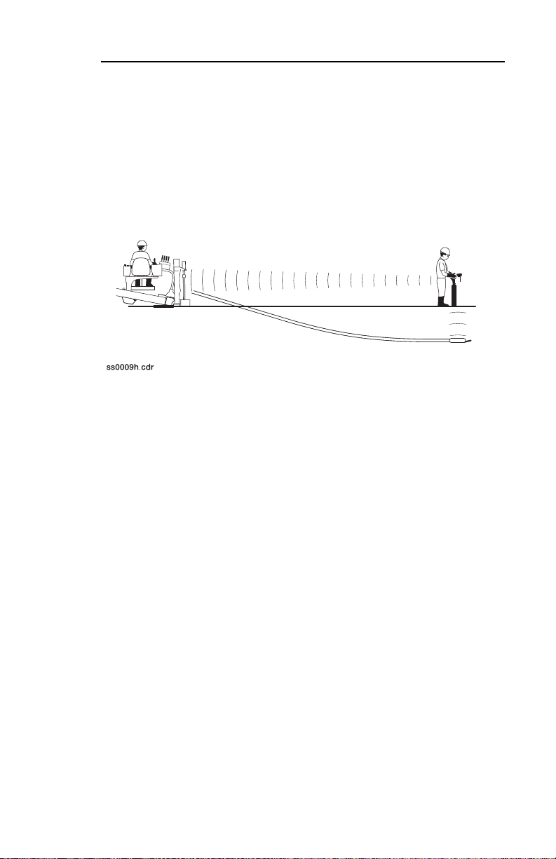
The 750/752 Display shows the drilling unit operator the same
information the tracking operator sees up to 2000’ (610 m) away.
It is designed for use with a 750/752 Tracker equipped with multichannel UHF radio and any Ditch Witch beacon. The 750/752
Display also features an RS232 port for use with the Trac
Management System option.
A brief description of the buttons and display on the 750/752
Display follows.

6 750/752 Display - CONTROLS
DISPLAY AND CONTROL OVERVIEW
DISPLAY AND CONTROL OVERVIEW
1. Beacon temperature display
2. Pitch/slope indicator and percentage (pipe number--TMS
option) display
3. Roll display
4. Target identifier
5. Depth estimate display
6. Display battery status indicator
7. Delete button
8. On/off button
9. Channel select button
10. Roll stop button
11. Recall button
12. Store button
13. Beacon battery status indicator
14. Beacon temperature indicator

750/752 Display - CONTROLS 7
DISPLAY AND CONTROL DESCRIPTIONS
DISPLAY AND CONTROL DESCRIPTIONS
Beacon Temperature Display
This arrow and number show beacon temperature in °C or °F.
Pitch/Slope Indicator and Percentage (Pipe Number--TMS Option) Display
This arrow and number show pitch beacon’s percent of grade. It
also shows pipe number if using Trac Management System
option.
Roll Display
This display shows beacon’s roll angle as it relates to clock
position.
Target Identifier
These arrows indicate approximate beacon location. Only one set
of arrows (fore/aft or left/right) is active at a time.

8 750/752 Display - CONTROLS
DISPLAY AND CONTROL DESCRIPTIONS
Depth Estimate Display
This display shows beacon depth estimate.
Display Battery Status Indicator
This indicator is used only when display unit is using C-cell
battery power. Replace batteries when indicator flashes.
Beacon Battery Status Indicator
This indicator shows beacon’s battery status (see beacon’s
instruction sheet).
Beacon Temperature Indicator
This indicator shows beacon’s temperature (see beacon’s
instruction sheet).

750/752 Display - CONTROLS 9
DISPLAY AND CONTROL DESCRIPTIONS
Delete Button
This button deletes last stored data.
• Press to delete information
about current pipe.
• Previous pipe number will
appear in numeric display when
data is deleted.
Second function: Press with
Recall button to delete all jobs in
internal logging memory.
IMPORTANT: Download jobs before deleting.
On/Off Button
This button turns display unit on or
off.
• Press to turn on.
• Press again to turn off.

10 750/752 Display - CONTROLS
DISPLAY AND CONTROL DESCRIPTIONS
Channel Select Button
This button selects between radio
channels when unit is on.
• Press and release to display
current channel.
• Press and hold to switch
channels.
IMPORTANT: Make sure display
and tracker are set to the same
channel.
This button is used in time change mode. See “Change Time”
section in SPECIAL FUNCTIONS.
Second function: Press with Recall button to select job to open.
“Init” and job number will be displayed.
Roll Stop Button
This feature is not yet available.
This button is used in year change
mode. See “Change Year” section
in SPECIAL FUNCTIONS.
si1069a.eps

750/752 Display - CONTROLS 11
DISPLAY AND CONTROL DESCRIPTIONS
Recall Button
This button allows operator to view
last stored data.
• Press to view data about
previous pipe in display.
Second function: Press with other
buttons to access second
functions.
si1066a.eps
Store Button
This button allows operator to store
currently displayed data.
• Press and hold after power up
to display serial number.
• Press to transmit data for TMS
over the serial interface.
• Pipe number will appear in
si1064a.eps
numeric display when data is
stored.
Second function: Press with Recall button to download all jobs
stored in internal logging memory to Trac Management System.

12 750/752 Display - CONTROLS
DISPLAY AND CONTROL DESCRIPTIONS

750/752 Display - SPECIAL FUNCTIONS 13
CHANGE TIME
SPECIAL FUNCTIONS
CHANGE TIME
To change time, day, and month:
1. Press and hold Channel Select button during power up. One digit of minutes will flash.
2. Press Channel Select button again to cycle through each of the remaining time digits, the day, and the month.
3. Press Roll Stop button to advance digits.
4. Press any other key to save changes, exit change mode and power unit off.
IMPORTANT: If changes are made inadvertently, enter
mode again to correct them.
CHANGE YEAR
To change year:
1. Press and hold Roll Stop button during power up. One digit will flash.
2. Press Roll Stop button to switch between units and tens position of year. The first two digits of the year are set automatically.
3. Press Channel Select button to advance digits.
4. Press any other key to save changes, exit change mode, and power unit off.
IMPORTANT: If changes are made inadvertently, enter
mode again to correct them.

14 750/752 Display - SPECIAL FUNCTIONS
CHANGE YEAR

750/752 Display - SETUP 15
SAFETY
SETUP
SAFETY
IMPORTANT: Read tracker operator’s manual and beacon
instructions before using with 750/752 Display.
Explosion possible. Never operate
transmitters near explosive devices or blasting
operations.
NOTICE: Operating two-way radios within 2’ (0.6 m) of either
display or tracker can cause erratic operation.
MOUNTING OPTIONS
A 750/752 Display is mounted in all of the most recent Ditch
Witch directional drilling unit operator’s stations and receives
power any time drilling unit key is in the on position.
The 750/752 Display unit is also available in a plastic case for use
with older units or units sold by other manufacturers. To set up a
750/752 Display in a case, install batteries.
1. Loosen screws on battery cover.
2. Insert 6 “C” cell alkaline batteries.
3. Close cover and tighten screws.
Next, position the unit 2-3’ (.5-1 m) above ground near drilling unit
operator’s station or in provided mount.

16 750/752 Display - SETUP
DATA LOGGING OPTIONS
DATA LOGGING OPTIONS
Data can be sent through a serial interface to a PC running the
Trac Management System software. Connect display to PC and
open a job in Trac Management System before powering up
display (see Trac Management System manual). Display will log
data internally if PC is not connected before unit is powered up.
FCC STATEMENT
This equipment has been tested and found to comply with the
limits for a Class B device, pursuant to Part 15 of the FCC rules.
These limits are designed to provide reasonable protection
against harmful interference in a residential installation. This
equipment generates, uses and can radiate radio frequency
energy and, if not installed and used in accordance with the
instructions, may cause harmful interference to radio
communications. However, there is no guarantee that
interference will not occur in a particular installation. If this
equipment does cause harmful interference to radio or television
reception, which can be determined by turning the equipment off
and on, the user is encouraged to try to correct the interference
by one or more of the following measures:
• Reorient or relocate the receiving antenna.
• Increase the separation between equipment and receiver.
• Consult the dealer or an experienced radio/TV technician for
help.
Shielded cables and I/O cords must be used for this equipment to
comply with the relevant FCC regulations.
Changes or modifications not expressly approved in writing by
The Charles Machine Works, Inc. may void the user’s authority
to operate this equipment.

750/752 Display - OPERATION MESSAGES 17
LOW BATTERY STATUS
OPERATION MESSAGES
LOW BATTERY STATUS
Flashing indicator signals low battery (3-4
hours of life remaining). If indicator flashes
at power up, replace batteries.
“Init” AND JOB NUMBER
This appears in display when recall and channel select keys are
pressed. Unit can store 10 jobs of up to 254 drill pipes each
before downloading.
“OnPC”
This appears in display if a job is initialized when unit is in
external logging mode.

18 750/752 Display - OPERATION MESSAGES

750/752 Display - SPECIFICATIONS 19
SPECIFICATIONS
Dimensions
Module Only
• Operating weight: 2.5 lb (1.1 kg)
• Power input: 6.5 V dc - 16 V dc at approx. 150ma
• Interface connectors: DB-15P (D-series sub-miniature
male)
Module with Case
• Operating weight: 6.5 lb (3 kg)
• Battery: 6 “C” cell alkaline
• Interface: MS5015 (7 pin)
• Antenna: TNC female
• Battery life: 20 hours
Display
roll depth beacon temperature
pitch left/right beacon battery status
beacon tracking arrows
Radio
• Type: 750 Display - two channel, dual conversion,
narrow-band FM
752 Display - nine channel, dual conversion,
narrow-band FM
• Frequency range: 420-470 mHz
• Sensitivity: -110dbm for 12db SINAD (typical)

20 750/752 Display - SPECIFICATIONS

750/752 Display - WARRANTY 21
WARRANTY
Ditch Witch Electronics
Limited Product Warranty Policy
Warranty Periods
New Product
A twelve-month period starts on the date of delivery to the end user:
Trackers: 750/752 Tracker Remote Displays: 750/752 Display
A six-month period starts on the date of delivery to the end user:
Beacons: 86B, 86BH, 86BHL, 88B, 88B-AT
A three-month period starts on the date of delivery to the end user:
Accessories: canoes and adapters
Used Product (Cosmetics)
A three-month warranty starts on the date of delivery to the end user. (Nonreturnable) All used products have an RS added after the serial number.
Service and Repair
A one-month warranty on labor starts on the date the unit is repaired, and a threemonth warranty on parts starts on the date the unit is repaired for all products.
Extended Warranty
The extended warranty may be purchased at the time the equipment is sold or
within thirty days of ownership. The extension is for an additional twenty-four
months, for a total coverage of thirty-six months.

22 750/752 Display - WARRANTY
Details and Exclusions
• The warranty includes only Ditch Witch Electronics products and accessories
that are manufactured and distributed by Ditch Witch Electronics. The warranty
compensates on defects in material or workmanship.
• Defects will be determined through inspection by Ditch Witch Electronics or
authorized repair centers. Original purchaser must make the defective item
available for inspection within 30 days of the date the part fails.
• The warranty is limited to replacement of the defective part. The replacement
part may be new or remanufactured. Repair and installation of defective part
will be at no charge when product or item is delivered to Ditch Witch Electronics
or an authorized repair center. The product or item will be returned at no charge
for return freight.
• The warranty periods do not represent the useful life of Ditch Witch Electronics
products and accessories.
• If Ditch Witch Electronics products are purchased for commercial purposes, as
defined by the commerical code, no warranties extend beyond the specific
terms set forth in this limited warranty. All other provisions of this limited
warranty apply, including duties imposed.
• Ditch Witch Electroinics products have been tested to deliver acceptable
performance in most conditions.
• This limited warranty applies to the original purchaser only. Some states or
jurisdictions do not allow exclusion or limitation of incidental or consequential
damages, so above limitation may not apply. This limited warranty gives
original purchaser specific rights that vary from state to state or jurisdiction to
jurisdiction.
• The Ditch Witch Electronics Equipment Registration Form must be completed
for each serial numbered product and submitted to Ditch Witch Electronics. The
information on the form is used to establish the warranty period start date.

750/752 Display - WARRANTY 23
• When the Ditch Witch Electronics Equipment Registration Form is not
processed and received by Ditch Witch Electronics, the Ditch Witch Electronics
shipping date is used to establish the warranty period start date.
• Product inspection and estimates may require that the unit be disassembled
and tested.
• Out-of-warranty inspection costs include labor accrued at the full labor rate plus
return freight.
• Approved out-of-warranty repair costs include parts, labor accrued at full labor
rate, plus return freight.
Revision E, January 2005

24 750/752 Display - WARRANTY

750/752 Display - 25
 Loading...