


DPC-5 Gen3
User Manual
v1.03
2" of 28"
Revision History: v1.03
Added support for several new devices Added Device
v1.01d
Added MIDI option for Expression Pedal jack
v1.01c
Added "dc" option to presets, to allow a preset to control only certain devices Added "INT" mode to allow using as a USB MIDI interface
v1.01b
Changed SysEx system to v1.0 Re-arranged device driver list
Added device driver for Empress Echosystem
v1.01a
Changed fast scrolling behaviour - only send program change when we "land" and release the button Changed SysEx Data format
v1.00k
Fixed an issue with the MultiJack not sending on the correct channels if Jack Channel set to something other than J000 Added experimental tempo setting for Zoom USB devices
v1.00g
Fixed bug when sending MIDI notes Fixed bank name bug!
Added support for Boss SY-300 (user programs only) Added support for Elektron Analog Drive
Changed looper record / play setup to reduce lag
(Unfortunately this means we lose looper pre/post control since we need to assign its button to reverse!) Added commands to keep mute relay alive in host mode
v1.00f
Fixed an issue with the D preset button canceling the mute Added support for Meris pedals
Fixes an issue with sending program numbers over 127 to certain devices
v1.00e
Fixed an issue with the loop 2 name being overwritten when TUNE or FAVE is called
v1.00d
*Added Memory Protect (default is OFF) to prevent accidental editing
*Added Hologram Dream Sequence device
*Added MIDI CC commands for loop activation (50-54 for L1-L5)
*Added MIDI CC commands for TRS activations (56 for CTL1, 57 for CTL2)
*Added MIDI CC commands for MUTE and TAP (58 for mute, 93 for tap)
*Streamlined mute / tune behaviour
*Changed Mute and Tune display to reflect what's actually happening
*Fixed an issue with "SAVE" not displaying after preset name saved
*Fixed issue with MultiJack device config, added TOGGLE to list of MultiJack destinations
v1.00c
*Fixed issue with CTL1 / CTL2 in preset mode v1.00b
*Fixed issue with expression roller not sending data v1.00
*Initial Release
Disaster Area Designs |
DPC-5 Gen3 |

3" of 28"
DPC-5 Gen3 Operation Manual
Firmware Revision 1.00d / released 12/29/16
1. Introduction
Thanks for purchasing a Disaster Area Designs DPC-5 Gen3 controller. We introduced the original DPC-5 way back in 2012, and it remained one of our top sellers for years. Eventually we had to discontinue it due to rising parts costs but we always planned to bring it back into our lineup. Finally, we’ve been able to incorporate the switching system from our popular DPC-8EZ along with some Gen3 horsepower to create the new DPC-5 Gen3.
The DPC-5 Gen3 is a compact pedalboard controller designed to interface with a wide variety of musical equipment. Up to four MIDI devices may be controlled along with up to five non-MIDI pedals using the DPC-5 Gen3 effects loops.
The DPC-5 includes a single TRS (tip-ring-sleeve) jack with switching contacts - these contacts may be assigned to a variety of functions including tap tempo or amplifier control.
If your MIDI device is equipped with a phrase looper / loop recorder mode, the DPC-5 Gen3 may be able to control it. Looper modes for the Strymon Timeline, Line 6 M9 / M13, and Eventide H9 are supported at this time. Boss DD-500 and Pigtronix Infinity looper support is planned for a future update. Note: Using the looper disables one of the available MIDI devices in scrolling and preset modes.
The DPC-5 Gen3 controller can also serve as a pedalboard clock source. The Tap and Clock modes serve to select preset beats-per- minute (BPM) tempo and the DPC-5 will send these clock signals out using a combination of MIDI and tap tempo output to a variety of compatible devices.
Disaster Area Designs |
DPC-5 Gen3 |
4" of 28"
2. Controls and Connections
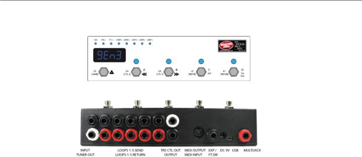
CONTROL PANEL
REAR PANEL
Input: Connect your guitar or the output of an effects pedal here.
Tuner Out: Connect the input of your tuner pedal here. The Tuner Output is separately buffered and is always active.
Loop 1 Send - Return: Loop 1 features a bypassable signal buffer. Bypass the buffer in the DPC Setup menu to allow this loop to be used with impedance sensitive pedals such as germanium fuzzes, vintage wahs, etc. Connect the black SEND jack to the input of each pedal, and the red RETURN jack to the output of the pedal.
Loops 2-5 Send - Return: Loops 2-5 have their own buffer section that is always active. Connect the black SEND jack to the input of each pedal you would like to control, and the red RETURN jack to the output of the pedal.
TRS CTL Out: The upper white jack is an isolated stereo / TRS connector designed to switch control functions on amplifiers or pedals. No audio is carried on this jack, only switching signals. This jack may be assigned to one of several types of control function including normally-closed, normally-open, momentary, or tap tempo.
Output: The lower black jack is the audio signal output. Connect this to the next pedal in your chain or directly to your amplifier or recording interface, etc. The output jack is separately buffered to ensure proper output impedance regardless of whether any pedals are engaged.
MIDI Output / MIDI Input: Standard 5-pin MIDI output, connects to your first MIDI pedal input. The MIDI output jack doubles as a MIDI input using a Disaster Area MIDI Y-cable (sold separately.) The MIDI input allows the DPC-5 Gen3 to accept incoming MIDI messages and merge them in with its own data stream.
Expression Input: The black jack is a multi-function connector that can accept an expression pedal or a momentary footswitch. Starting in v1.01d the Expression jack may also serve as an additional MIDI out just like the MultiJack. Consult the Expression section for more details.
DC 9V: Standard DC power supply input, 9V center negative. The DPC-5 Gen3 requires approximately 80mA if used by itself. If an external USB HOST device is connected, the DPC-5 will need to be supplied with enough current to power both itself and the USB device.
USB MIDI: |
The standard DPC-5 firmware allows the USB port to function as a MIDI interface for your compatible PC, Mac, or |
iPad (using the Apple Camera Connection Kit.) The DPC-5 will receive and send MIDI messages over USB for device control. |
|
USB HOST: |
If the USB Host firmware is installed, the DPC-5 USB port may be used to send and receive MIDI messages to |
supported USB devices. |
|
Status Indicator: |
This LED that blinks to let you know the pedal is working. It also blinks at a slower rate to indicate that the pedal is in |
boot loader mode during a firmware update. |
|
MultiJack: |
The final jack on the panel is our astounding MultiJack! The MultiJack can do all kinds of cool stuff, like receive |
expression or tap tempo, send taps to your devices, or even send MIDI to additional devices.
Disaster Area Designs |
DPC-5 Gen3 |

5" of 28"
3. Connecting your Pedals to the DPC-5
So you’ve got this… thing. It’s a box with a whole bunch of jacks, switches and lights. How do you make sense of it? How do you get it integrated into your rig so that you can stop tap-dancing and start playing?
The first step is to connect your pedals to the DPC-5. We’ll take it one step at a time.
Here’s the DPC-5 back panel - we covered it in the last section. Let’s check out the left side, which has fourteen (14) 1/4” phone jacks. We’ve color-coded them to help make identifying them a bit easier.
The ten (10) jacks in the middle are the bypass control loops. They’re numbered L1-L5 from left to right looking at the back panel, but when the DPC is in playing position the signal flows from RIGHT to LEFT, as is common with guitar effects setups. Connect a patch cable from Loop 1 send (that’s the black one on top) to your first pedal’s input. Then connect another patch cable from Loop 1 return (the red one right under it) to that pedal’s output. Repeat this for all of the pedals you’d like to place in the DPC-5 Gen3 loops. (Yes, we know the pedals in the drawing are upside down! If we draw them the other way, the wires will cross and the diagram is hard to read!)
IMPORTANT NOTE: The DPC-5 Gen3 can control a maximum of five non-MIDI pedals in its bypass loops and a maximum of four MIDI pedals, plus an additional Disaster Area device. Need more loops? Grab a DPC-8EZ and instantly control thirteen non-MIDI devices!
Disaster Area Designs |
DPC-5 Gen3 |
"6 of "28
DPC-5 Loop Order - The DPC-5 Gen3 loops are all placed in series with each other, and the order is always: Input -> Loop1 -> Loop2 -> Loop3 -> Loop4 -> Loop5 -> Output.
The DPC-5 cannot re-arrange loop order.
Loops and Delay / Reverb Trails - the DPC-5 loops are hardware based and as such they bypass both the input and the output of each connected device. While this does provide the absolute cleanest switching available, it also cuts off delay and reverb “trails.” If your delay or reverb pedals have MIDI, your best bet is to place them after the DPC-5 and control them remotely. Most MIDI pedals support “trails” bypass switching using a MIDI command, and this also frees up loops for your other pedals.
Device Order - There is no real right or wrong order to connect your pedals to the DPC. If you have them wired in a certain way on your pedalboard and you like the way it sounds, then go for it! If you’re setting up a board for the first time, or you’re moving your pedals around, here are some guidelines we use when designing pedalboards.
1.Place any effects that are sensitive to your guitar level as early in the chain as possible. These include compressors, auto-wah / filtering pedals, etc.
2.If you have a vintage-style fuzz pedal that doesn’t respond well to buffers, place it in LOOP 1, then bypass the buffer in the DPC setup.
3.Place your drive or distortion pedals in order starting with the highest-gain and ending with the lowest-gain. The reason we recommend this is because if you have a high-gain pedal placed later in the chain, boosting it with a lower gain pedal in front won’t increase your output level. So generally fuzz -> distortion -> overdrive -> boost.
4.Consider placing your MIDI-capable pedals outside of the DPC-5 loops. The Preset and MIDI modes will allow you to change settings and bypass these devices so they don’t need to be in a loop to have control over them.
On the boards we build for demonstration purposes we typically set up something like this:
Loop 1 - Compressor or Fuzz (buffer on for compressor, off for fuzz)
Loop 2 - High gain drive
Loop 3 - Low gain drive
Loop 4 - Polyphonic octave pedal
Loop 5 - Modulation pedal (chorus, flanger, tremolo, etc.)
Then we run out of the DPC-5 into a volume pedal, then on to the input of a MIDI delay.
We run out of the MIDI delay into a MIDI reverb, usually in stereo, and then out to one or two amplifiers.
These are just some guidelines and ideas - email us or post on our user group if you have any questions!
Disaster Area Designs |
DPC-5 Gen3 |
7" of 28"
4. Setting up your DPC-5 Gen3 - Hardware Options
The DPC-5 Gen3 has several hardware options that we can access in the Setup menu. These options reconfigure the way the DPC responds and change how its hardware functions work.
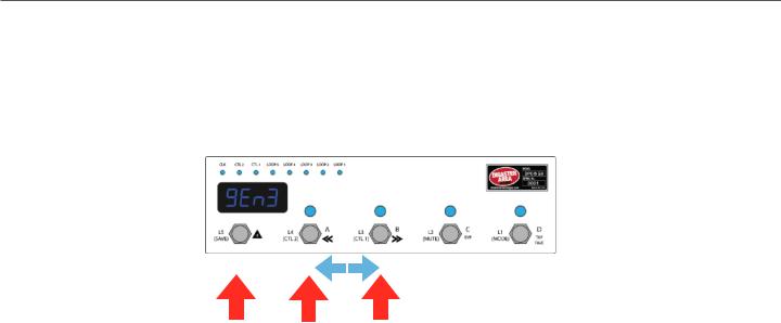
To enter the setup menu, power the DPC-5 Gen3 on and wait until you see “Gen3” on the display, then hold the A and B buttons. When the display scrolls “SETUP” release the buttons. Once you are in the setup menu, tap the A and B buttons to select from the available menus and tap the SAVE button to enter / exit the menus. Once you’re inside a menu, you can tap the A and B button to change the menu options. When you’re done, hold SAVE to save the setup and start using the controller.
TAP TO ENTER / EXIT MENUS |
TAP TO CHANGE MENU OPTION |
HOLD TO SAVE AND EXIT SETUP |
HOLD DURING BOOT TO ENTER SETUP |
There are lots of setup options here, but we will focus on the ones that change how the loop switching and amp control functions work.
Loop 1 Buffer
Tap the A or B button until you see “BUFF.” This menu allows you to bypass or engage the signal buffer for Loop 1. The other loops have their own buffer that is always engaged. Tap SAVE to edit the buffer, then tap A or B to change the buffer setting. If you’re using a vintage fuzz in Loop 1, set this to “bOFF.” Otherwise leave it as “b ON,” and tap SAVE to exit the setup menu.
Loop Pop-Stopping
Next, we have the loop pop-stop function, labeled as “POP.” This menu has four settings: OFF - no noise reduction
p LO - the main output will mute for a very short time when loops are changed pMED - the main output will mute for a slightly longer time when loops are changed p HI - the main output will mute for the maximum time when loops are engage.
By default, POP is set to p LO. This will generally silence any troublesome pedals, preventing them from popping or clicking when you change presets. If the delay bothers you, set POP = OFF. In most cases the popping won’t be objectionable even with noise reduction disabled, but if the popping or clicking is irritating, increase POP until it stops.
Tuner Mute
The DPC-5 has a hardware tuner output, which is a buffered copy of the signal from the main input. The tuner output is always active, and you can engage the DPC-5 hardware tuner mute from most modes by holding the C button. This will silence the main output but the tuner output stays active.
Optionally, if one of your MIDI pedals is equipped with a tuner function (Eventide H9, Pitchfactor, Line 6 M-Series, Zoom MultiStomp, Atomic AmplifFIRE and some others) then the DPC-5 Gen3 can activate this instead. If you plan to use one of your MIDI pedals for tuning, we recommend that you place it either before or after the DPC-5, and not in one of its loops.
The tuner mute menu is labeled “TUNR.” It has five settings:
MUTE - activating the tuner mute will silence the main output, allowing you to tune by using the hardware tuner out tunA - use the “A” device at MIDI channel 1 for tuning.
tunB - use the “B” device at MIDI channel 2 for tuning. tunC - use the “C” device at MIDI channel 3 for tuning. tunD - use the “D” device at MIDI channel 4 for tuning.
Please note that the selected device must have a tuner function for this option to have any effect! If your device doesn’t have a tuner, there’s no way we can use it to tune! The DPC-5 Gen3 will engage preset zero when you invoke the tuner, so make sure that preset has all of your devices bypassed to ensure a good clean signal for tuning!
Disaster Area Designs |
DPC-5 Gen3 |
8" of 28"
TRS Amp Control
The white jack above the main output is an isolated switching output, designed to control amplifier functions or other remote switching tasks. It uses optical relays to simulate hardware footswitch contacts, so they’re usable with many different types of devices. Almost anything that uses a 1/4” input for foot switching may be controlled by the TRS Amp Control jack.
The TIP of the jack is controlled by the CTL1 function, and the RING of the jack is controlled by CTL2. You may edit the settings for each output independently in the Setup Menu, under the “CTL1” and “CTL2” menus. These menus have five options:
NO - the output will function as a normally open contact. The LED for that channel will light when the switch contact is CLOSED. This is the most common type of footswitch control.
NC - the output will function as a normally closed contact. The LED for that channel will light when the switch is OPEN. This type of control is less common, but it is used by Fender type amplifiers for reverb switching.
MOM - the output will function as a momentary switch. When the CTL1 or CTL2 function is activated the associated contact will CLOSE for a brief period, then OPEN again. Used by many pedal manufacturers including Bogner and Suhr for remote switching.
TAP+ - the output will function as a normally open tap tempo contact. This function will disable CTL1 or CTL2 in manual mode, instead assigning it to the Clock mode.
TAP- - the output will function as a normally closed tap tempo contact. Normally closed taps are less common, used primarily for Roland / Boss effects. This function will disable CTL1 or CTL2 in manual mode, instead assigning them to the Clock mode.
Please note that while the TRS Amp Control jack is isolated from the ground of the DPC-5 audio path, the two contacts in the jack share a common ground connection. In many cases you can use a y-cable to control two different functions with the same jack, but if the two devices are at different ground potentials you may experience noise or interference. Disconnect one device at a time to see whether the noise goes away.
D Footswitch Assign
The right-hand footswitch labeled “D” may be assigned to a variety of destinations in Preset Mode. By default, we map this footswitch to Tap Tempo / Clock. The “D FS” option in Setup Mode allows you to change how the D footswitch behaves. This menu has three options:
TAP - The D footswitch sends tap tempo commands. If the CLK mode is disabled or set to TAP, then taps are send as MIDI CC messages. If CLK is set to PST or GLB, then tapping this footswitch will control the DPC-5 internal SMARTClock function.
FAVE - The D footswitch acts as a Favorite switch, tapping it engages the Favorite preset or returns to the previous setting if the Favorite preset was active. The Favorite preset is global, meaning that it is the same regardless of which bank the user starts in. You can use this preset for a “lead” setting, for example, or for a particular sound that you use often.
PRST - The D footswitch recalls the fourth preset in each preset bank, allowing the user to access four presets instead of the usual three in each bank.
When you have set all of these options to your liking, hold the SAVE button to save the configuration and restart the DPC.
Disaster Area Designs |
DPC-5 Gen3 |
9" of 28"
4. Getting Started with MIDI
MIDI might seem kind of intimidating or frustrating at first, but it’s really not too complicated. MIDI stands for Musical Instrument Digital Interface, and it was created way back in the 1980’s as a method for synthesizers to talk to each other. Today, we can use it for linking synths, effects units, computers, drum machines, samplers, pedals, and more.
MIDI units come in two basic types - controllers and devices. The DPC-5 is a controller, so it sends out commands to the gear on your pedalboard. Your Timeline, BigSky, H9, etc. are devices, so they receive commands and change in response to them.
With me so far? Good!
MIDI gear is linked by some kind of hardware connection, usually a five-pin cable with a big round plug on each end. Sometimes devices can accept MIDI over a USB connection or using a non-standard connector like a 1/4” plug. Generally you can link up multiple devices in a daisy-chain kind of like you'd do with regular pedals, by connecting the MIDI OUTPUT or THRU of the first device to the MIDI INPUT of the second device and so on. There are some devices that won’t re-transmit MIDI, or that will mangle / interfere / drop messages, so sometimes you have to get creative with your routing.
Each MIDI device receives commands on one or more MIDI channels, and the standard MIDI specification allows for up to 16 channels to be transmitted on the same cable. Sometimes, devices can receive on any channel they see (that’s called Omni) but usually they’ll be set to listen to only a single channel.
The DPC-5 series are designed to transmit commands to lots of devices - up to four at the same time, and we send out commands to each device on its own MIDI channel. Again, the same cable can carry all of those commands so that makes it a bit more convenient for us when we’re putting together a pedalboard or rack system.
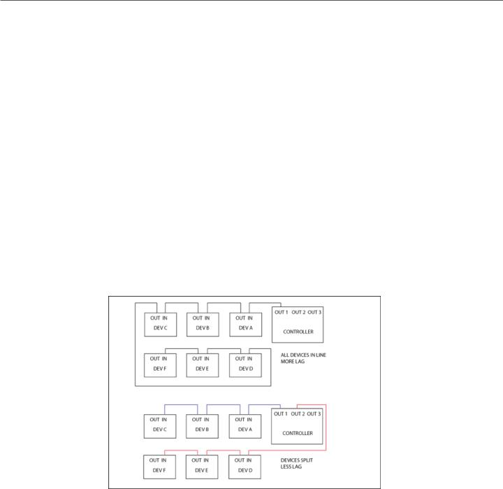
One important thing to consider - the more MIDI devices you have chained end-to-end, the greater the chance that your MIDI communication will be slow or unreliable. We call this “MIDI lag,” and it’s a bummer. To get around this, you can use a controller with multiple MIDI outputs or a hardware MIDI Thru box to split your MIDI signal to two or more short chains.
Please note that the order that you plug your MIDI devices in does not have to be the same as the order you plug their audio cables!
Disaster Area Designs |
DPC-5 Gen3 |
 Loading...