


Disaster Area Designs
www.disasterareadesigns.com
DPC-5 Operation Manual
Firmware revision 1.15c
December 2013
Thank you for purchasing the Disaster Area DPC-5 Pedal Controller. The DPC-5 is a compact effects switching system with built-in MIDI control. It is designed to switch up to five separate effects loops and to change presets on several external MIDI devices simultaneously, to simplify tone changes in a live or studio setting.
CONNECTIONS:
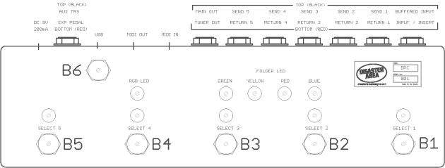
Connect your guitar using a 1/4" shielded instrument cable to the Buffered Input or Unbuffered Input jack. If the Buffered Input jack is used, the Unbuffered Input may be used as an "insert" to connect an additional always-on device. The buffer signal is sent through the "ring" terminal, and the bypass relay matrix is fed by a signal on the "tip" terminal. Volume pedals and compressors are popular choices for the insert.
The next five pairs of 1/4" jacks are the sends and returns for the effects loops. The top (black) jacks are the send channels, and the lower (red) jacks are the returns. The send jacks may be used to feed additional amplifiers, and are muted when their associated relays are "off."
The final two jacks in the main section are the outputs. The main output is on the top (black) and the tuner output is on the bottom (red.) When the pedal is set to tuner mute, the main output is shorted to ground through a relay and its output is muted. The tuner output is always active, and is fed from the output of the buffer matrix. It will not be active if the unbuffered input is used for the guitar input.
The MIDI input and Output are described in the MIDI section below.
The USB-Mini-B jack is used for firmware update and customization. The MIDI jacks will not be functional if the USB is connected. Additionally, the USB connection can cause noise or interference with the guitar signal when connected.
The TRS Amp / Pedal control and Expression pedal jacks are next. TRS AC is the top (black) jack, an the Expression pedal is the lower jack (red.)

The TRS AC jack may be set to control an amplifier or pedal. It may switch the Tip and Ring contacts to the Sleeve contact. This jack may also be used for controlling a momentary type switch for tap tempo, or for toggling the "favorite" setting on certain Strymon pedals with the DSC adapter cable.
The power jack is 2.1mmID, center negative, 9V DC 200mA minimum. The DPC-5 may be powered by one of the high-current outputs on the Voodoo Labs Pedal Power series power supplies, or with an optional DC power supply.
Typical DPC-5 Connection Diagram
Revision 1b and higher boards have a group of DIP switches inside, accessible by removing the rear panel screws. SW1 routes the tuner buffer to the Unbuffered input jack, and SW2 takes the tuner signal from the Buffered input. If using the Unbuffered input jack, the user can choose to set SW1 to ON and enabling the tuner, or setting it to OFF to disable the tuner send and maintain a pure straight-wire path for the input signal. Regardless of the chosen switch setting, only one of these switches should be ON at any time. Having both set to ON can cause crosstalk or excessive noise and should be avoided.
DIP Switch Settings
SETUP AND USE:
The upper switch (button 6) is the mode / config switch. The lower five switches are the preset / select switches. Throughout this document, they may be referred to as B1-B6.
The button mapping is as follows:
The DPC-5 features a configuration menu that allows changing some of the parameters of the controller. To enter Config Mode, press and hold B6 at power-up. To perform a factory reset, press and hold B1 + B5 at power-up. WARNING! A factory reset will erase all presets and custom configurations saved in the DPC-5 memory!
CONFIG MODE
Config Mode has two available pages. Tap B6 to change pages.
Expression / Tap Setup (indicated by RGB LED red)
Tap the select buttons to assign Expression destinations and tap controls B1 Enable / Disable Tap Tempo for External MIDI A & B
B2 Expression Roller Assign: Aux Red = Expression for External MIDI A & B, Aux Blue = Expression for External MIDI C & D, Select 2 LED = Looper Level
B3 Expression Jack Assign: Aux Yellow – Expression for External MIDI A & B, Aux Green = Expression for External MIDI C & D, Select 3 = Looper Level, All 3 on = Tap Tempo or R2R dual remote switch
B4 TRS Setting: LED Off = Latching TRS amp control, LED On = TRS Tap (sends taps to TRS jack,) LED Blinking = Momentary TRS amp control for devices that require pulse / momentary control such as TC Electronics Stereo Chorus + Flanger or Bogner Ecstasy pedals
B5 Enable / Disable Tap Tempo for External MIDI C & D
 Loading...