


 Loading...
Service Manual
Model Number
DS5629
UL Part Number
6900471359
IMPORTANT SAFETY INFORMATION: Always read this manual first before attempting to service this stove. For your safety, always comply with all warnings and safety instructions contained in this
manual to prevent personal injury or property damage. |
REV PCN DATE |
|
Dimplex North America Limited
1367 Industrial Road  Cambridge ON Canada N3H 4W3
1-888-346-7539  www.dimplex.com
In keeping with our policy of continuous product development, we reserve the right to make changes without notice.
© 2015 Dimplex North America Limited
9-Sep-11
02 13147 16-Apr-12
03 25-May-15
7400490000R03

TABLE OF CONTENTS |
|
OPERATION.. . . . . . . . . . . . . . . . . . . . . . . . . . . . . . . . . . . . . . . . . . . . . . . . . . . . . . . . . |
3 |
MAINTENANCE. . . . . . . . . . . . . . . . . . . . . . . . . . . . . . . . . . . . . . . . . . . . . . . . . . . |
. . . . 4 |
EXPLODED PARTS DIAGRAM. . . . . . . . . . . . . . . . . . . . . . . . . . . . . . . . . . . . . . . |
. . . . 5 |
WIRING DIAGRAM. . . . . . . . . . . . . . . . . . . . . . . . . . . . . . . . . . . . . . . . . . . . . . . . . . . . |
6 |
LIGHT BULB REPLACEMENT . . . . . . . . . . . . . . . . . . . . . . . . . . . . . . . . . . . . . . . |
. . . . 7 |
UPPER LIGHT BULB REPLACEMENT. . . . . . . . . . . . . . . . . . . . . . . . . . . . . . . . . . . . . . . . . . . . . . . . . . . . . . . |
7 |
LOWER LIGHT BULB REPLACEMENT. . . . . . . . . . . . . . . . . . . . . . . . . . . . . . . . . . . . . . . . . . . . . . . . . . |
. . . . .7 |
FLAME ROD REPLACEMENT. . . . . . . . . . . . . . . . . . . . . . . . . . . . . . . . . . . . . . . . . . . |
7 |
FLICKER MOTOR REPLACEMENT . . . . . . . . . . . . . . . . . . . . . . . . . . . . . . . . . . . |
. . . . 8 |
REMOTE CONTROL RECEIVER REPLACEMENT. . . . . . . . . . . . . . . . . . . . . . . . . . . |
8 |
CONTROLS REPLACEMENT. . . . . . . . . . . . . . . . . . . . . . . . . . . . . . . . . . . . . . . . |
. . . . 9 |
SWITCHES. . . . . . . . . . . . . . . . . . . . . . . . . . . . . . . . . . . . . . . . . . . . . . . . . . . . . . . . . . . . . . . . . . . . . . . . . |
. . . . .9 |
THERMOSTAT . . . . . . . . . . . . . . . . . . . . . . . . . . . . . . . . . . . . . . . . . . . . . . . . . . . . . . . . . . . . . . . . . . . . . . |
. . . . .9 |
POWER CORD REPLACEMENT. . . . . . . . . . . . . . . . . . . . . . . . . . . . . . . . . . . . . . . . . |
9 |
HEATER ASSEMBLY REPLACEMENT.. . . . . . . . . . . . . . . . . . . . . . . . . . . . . . . . . . . |
10 |
TROUBLESHOOTING GUIDE. . . . . . . . . . . . . . . . . . . . . . . . . . . . . . . . . . . . . . . . |
. . . 11 |
Always use a qualified technician or service agency to repair this stove.
! NOTE: Procedures and techniques that are considered important enough to emphasize.
 CAUTION: Procedures and techniques which, if not carefully followed, will result in damage to the equipment.
 WARNING: Procedures and techniques which, if not carefully followed, will expose the user to the risk of fire, serious injury, or death.
2 |
www.dimplex.com |
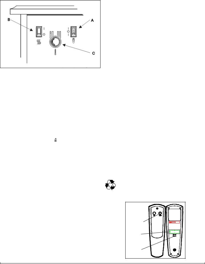
OPERATION
Figure 1
To access the controls go to the back of the Stove. (Figure 1)
A.. 3-Position Switch
The switch has two ON positions marked with “-“ and “=”. The “-“ position is for manual operation. In this position the built-in remote control is bypassed. The “=” position is for operating the unit with the provided remote control. When in “=” position the unit is operated with the ON and OFF buttons of the remote control.
When the switch is in the center position the unit is off.
B.. Heater On/Off Switch 

The Heater On/Off Switch supplies power to the heater fan and the heater element.
C.. Heater Thermostat Control 
To adjust the temperature to your individual requirements, turn the thermostat control clockwise all the way to turn on the heater. When the room reached the desired temperature, turn the thermostat knob counter clockwise until you hear a click. Leave in this position to maintain the room temperature at this setting. For additional heat, turn clockwise until you hear the click again and the heater will turn on. To turn the heater off, switch the Heater On/Off switch to the OFF position.
! NOTE: When the heater is switched ON, the heater fan will operate. The heater element may or may not be on, depending on the thermostat control setting (See “Heater Thermostat Control”)
Resetting the Temperature Cutoff Switch
Should the heater overheat, an automatic cut out will turn the heater off and it will not come back on without being reset. It can be reset by switching the 3-Position Switch to OFF and waiting 5 minutes before switching the unit back on.
 CAUTION: If you need to continuously reset the heater, unplug the unit and call Dimplex North America Limited at 1-800-668-6663.
Remote Control
The stove is supplied with a radio frequency remote control. This remote control has a range of approximately 50 feet (15.25 m), it does not have to be pointed at the stove and can pass through most obstacles (including walls). It is supplied with one of hundreds of independent frequencies to prevent interference with other units.
! NOTE: Before attempting any operation with the remote, pull the plastic insulator strip out from between the remote casing and battery cover (Figure 2).
Remote Operation
The stove is supplied with an integrated on/off remote control
!NOTE: Ensure that the stove 3-Position Switch is set to the remote control setting.
To operate, push the ON button to turn stove on, push the OFF button to turn the stove off.
Remote Control Initialization/Reprogramming
If the remote control or remote control receiver has been replaced, follow these steps to initialize the remote control and receiver:
1.Set the 3-Position Switch to OFF.
2.Wait a minimum of five (5) seconds and set the 3
Position Switch to the “=” position (Figure 1A).
3.Within 10 seconds of re-acquiring power, press the ON button located on the remote control.
!NOTE: You will have only 10 seconds to perform this last step. Failure to do so will result in these steps needing to be followed again.
This will synchronize the remote control and receiver.
Battery Replacement
To replace the battery:
1.Slide battery cover open on the remote control (Figure 2).
2.Install one (1) 12-Volt (A23) battery in the battery holder.
3.Close the battery cover
Battery must be recycled or disposed of properly. Check with your Local Authority or Retailer for recycling advice in your area.
Figure 2
On
Button 

Off Button
Plastic
Strip
Battery
Cover
3

MAINTENANCE
 WARNING: Disconnect power before attempting any maintenance or cleaning to reduce the risk of fire, electric shock or damage to persons.
Light Bulb Replacement
Allow at least 5 minutes for light bulbs to cool off before touching bulbs to avoid accidental burning of skin.
Light bulbs need to be replaced when you notice a dark section of the flame or when the clarity and detail of the log exterior disappears. There are two bulbs under the log set which generate the flames and embers.
Tool Requirements
Phillips screw driver
Helpful Hints
It is a good idea to replace all light bulbs at one time if they are close to the end of their rated life. Group replacement will reduce the number of times you need to open the unit to replace light bulbs.
Upper Light Bulb Requirements
Quantity of 1 clear chandelier or candelabra bulbs with an E-12 (small) socket base, 7 watt rating.
Upper Bulb Replacement
1.Open door by pulling the handle.
2.Locate the upper bulb bracket.
3.Bend light retainer bracket down.
4.Locate and remove the light bulb.
5.Insert new bulb.
6.Bend light retainer bracket back into its original position.
7.Close the door.
Lower Light Bulb Requirements
Quantity of 2 clear chandelier or candelabra bulbs with an E-12 (small) socket base, 60 watt rating.
Lower Bulb Replacement
1.Open door by pulling the handle.
2.Remove the screw from the logset located in the center of the emberbed and remove the logset from the unit.
3.Locate and examine the bulbs to determine which bulb(s) required replacement.
4.Locate and remove the light bulb(s).
5.Insert new bulb(s).
6.Install the logset into the unit, pushing firmly against the glass. Replace the logset retaining screw into the ember bed.
7.Close the door.
Glass Cleaning
The clear door is cleaned in the factory during the assembly operation. During shipment, installation, handling, etc., the clear door may collect dust particles, these can be removed by dusting lightly with a clean dry cloth.
To remove fingerprints or other marks, the clear door can be cleaned with a damp cloth. The clear door should be completely dried with a lint free cloth to prevent water spots. To prevent scratching, do not use abrasive cleaners or spray liquids on the clear door surface.
Plastic Door Cleaning
To remove fingerprints or other marks, the clear door can be cleaned with a damp cloth. The clear door should be completely dried with a lint free cloth to prevent water spots. To prevent scratching, do not use abrasive cleaners or spray liquids on the clear door surface.
Stove Surface Cleaning
Use warm water only to clean painted surfaces of the Compact Stove. Do not use abrasive cleaners.
Servicing
Except for light bulb replacement and cleaning described above, an authorized service representative should perform any other servicing.
4 |
www.dimplex.com |
Loading...