


DFG2562
Service Manual
Model Number:
DF2426
DF2550
DFG2562
BF9000
UL Part Number
6905050100 to 500
6907560100
7400250000R03
In keeping with our policy of continuous product development, we reserve the right to make changes without notice.
© 2011 Dimplex North America Limited
Dimplex North America Limited
1367 Industrial Road
Cambridge ON Canada N1R 7G8
1-888-346-7539 www.dimplex.com
REV PCN DATE
00 - 22-JUL-11
01 - 26-AUG-11
02 13118 13-DEC-11
03 - 31-JAN-14
IMPORTANT SAFETY INFORMATION: Always read this manual rst before attempting to service this
replace. For your safety, always comply with all warnings and safety instructions contained in this
manual to prevent personal injury or property damage.

2 www.dimplex.com
Always use a qualied technician or service agency to repair this replace.
!
NOTE: Procedures and techniques that are considered important enough to emphasize.
CAUTION: Procedures and techniques which, if not carefully followed, will result in damage to the
equipment.
WARNING: Procedures and techniques which, if not carefully followed, will expose the user to the
risk of re, serious injury, or death.
Operation ...........................................................3
Maintenance
.........................................................4
Exploded Parts Diagram: DF2426, DF2550, DFG2562, 6905050100-500
........5
Wiring Diagram: DF2426, DF2550, DFG2562, 6905050100-500
................6
Exploded Parts Diagram - BF9000, 6907560100
............................7
Wiring Diagram - BF9000, 6907560100
...................................8
Preparation for Service
................................................9
Light Assembly Replacement
..........................................9
MOD 0-A ..................................................................... 9
MOD B ...................................................................... 10
Flicker Motor/Flicker Rod Replacement .................................10
Heater Assembly Replacement
........................................11
High Temperature Cutout Replacement
.................................11
3-Position or Heater Switch Replacement
...............................12
Thermostat replacement
..............................................12
Remote Control Receiver Replacement
.................................12
LED Log Driver Replacement
..........................................13
Power Cord Replacement
.............................................13
Assembly Part Pictures
..............................................14
LOWER ELECTRICAL HOUSING ............................................... 14
UPPER PANEL TERMINAL BLOCK CONNECTIONS ................................ 14
HEATER ASSEMBLY CONNECTIONS ............................................ 15
HEATER ASSEMBLY CONNECTIONS WITH HIGH TEMPERATURE CUTOUT ............ 15
REMOTE CONTROL RECEIVER BOARD CONNECTIONS ............................ 16
THERMOSTAT DIAL, HEATER AND 3-POSITION SWITCHES ......................... 16
Troubleshooting Guide ...............................................17
TABLE OF CONTENTS

3
the remote casing and battery cover (Figure 2).
!
NOTE: The remote control is an EEPROM system;
therefore if power is interrupted for whatever reason,
the built-in receiver board will hold the memory of
the remote’s radio frequency for up to 24 hours. The
remote should continue to operate the replace as
normal once unit is re-powered. Re-initialization of the
remote control to the replace should only be required
if there is a loss of power to the receiver for longer than
24 hours. (i.e. power failure, main power switch is turned
off).
To operate, push the ON button to turn replace on, push
the OFF button to turn the replace off.
!
NOTE: Ensure that the replace 3-Position switch is
set to the remote control setting.
Remote Control Initialization/Reprogramming
If the hand held transmitter or receiver board has been
replaced, follow these steps to initialize the transmitter and
receiver:
1. Place the 3-Position Switch (Figure 1A) in the OFF
(“O”) position.
2. Wait a minimum of ve (5) seconds and then place the
3-Position Switch in the Remote Control (“=”) position.
3. Within 10 seconds of changing the switch position,
press the ON button located on the remote control
(Figure 2).
This will synchronize the remote control and the replace
receiver.
!
NOTE: You will have only 10 seconds to perform this
last step. Failure to do so will result in these steps
needing to be followed again.
Battery Replacement
To replace the battery:
1. Slide battery cover open on the remote control
(Figure 2).
2. Install one (1) 12-Volt (A23) battery in the battery
holder.
3. Close the battery cover
Battery must be recycled or disposed of properly.
Check with your Local Authority or Retailer for
recycling advice in your area.
OPERATION
A. 3-Position Switch
The switch has two On positions marked. The “ -- “ position
is for manual operation. In this position the built-in remote
control is by-passed. The “ = “ position is for operating
the unit with the provided remote control. When in remote
control (“ = “) position the unit is operated with the On and
Off buttons of the remote control.
When the switch is in the center “o” position the unit is off.
B. Heater Switch
The Heater Switch supplies power to the heater fan and the
heater element. When the switch is in the ON position the
heater operates if the thermostat calls for heat.
C. Heater Thermostat Control
To adjust the temperature to your individual requirements,
turn the thermostat control clockwise all the way to
turn on the heater. When the room reaches the desired
temperature, turn the thermostat knob counter-clockwise
until you hear a click. Leave in this position to maintain the
room temperature at this setting. For additional heat, turn
clockwise until you hear the click again and the heater will
turn on.
Resetting the Temperature Cutoff Switch
Should the heater overheat, an automatic cut out will turn
the replace off and it will not come back on without being
reset. It can be reset by switching the 3-Position Switch to
Off and waiting ve (5) minutes before switching the unit
back on.
!
NOTE: If operating the unit with a remote control, the
remote may require re-initializing after turning the power
off.
CAUTION: If you need to continuously reset the heater,
disconnect power and call Dimplex customer service at
1-888-DIMPLEX (1-888-346-7539).
Remote Control
The replace is supplied with a radio frequency remote
control. This remote control has a range of approximately
50 feet (15.25 m), it does not have to be pointed at the
replace and can pass through most obstacles (including
walls). It is supplied with one of hundreds of independent
frequencies to prevent interference with other units.
!
NOTE: Before attempting any operation with the
remote, pull the plastic insulator strip out from between
Figure 2
Off Button
On
Button
Battery
Cover
Plastic
Strip
Figure 1
A
B
C
4 www.dimplex.com
Ember Bed
Assembly
Front Edge
Rear Tab
Back Ledge
Mirror
MAINTENANCE
Light Bulb Replacement (Mod 0-A Only)
Allow at least ve (5) minutes for light bulbs to cool before
touching bulbs to avoid accidental burning of skin.
Light bulbs need to be replaced when you notice a dark
section of the ame or when the clarity and detail of the
log ember bed exterior disappears. There are two 2 bulbs
under the log set, which generate the ames and embers.
Light Bulb Requirements
Quantity of two 2 clear chandelier or candelabra bulbs with
an E-12 (small) socket base, 60 Watt rating. Example: GE
60BC or Philips 60 CTC.
Do not exceed 60 Watts per bulb.
Helpful Hints
It is a good idea to replace both light bulbs at one time
if they are close to the end of their rated life. Group
replacement will reduce the number of times you need to
open the unit to replace light bulbs. Care must be taken
when removing the log set.
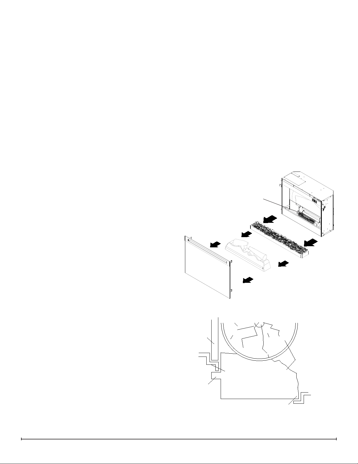
To Access The Lower Light Bulb Area: (Figure 3)
1. Remove front glass assembly.
2. Pull the front edge of the plastic Ember Bed, plastic
grate or Media Tray (depending on Model) up and
forward until the rear tab releases from the ledge
located at the bottom of the partially reective glass.
!
IMPORTANT: Only handle the log set by the ember bed.
!
NOTE: Log set ts tightly into rebox, some force may
be necessary to remove.
3. Set Log Set/ Media Tray in front of replace.
4. Disconnect icker from motor (see Figure 3).
5. Unscrew bulbs counter clockwise.
6. Insert new bulbs.
7. Reconnect icker to motor.
8. Replace the log set by inserting the front edge of the
log set and push down on the rear edge of the ember
bed until it snaps into place (Figure 4).
!
NOTE: Ensure the log set is installed tightly under the
back ledge to prevent light leakage.
9. Replace glass assembly.
Glass Cleaning
The front glass is cleaned in the factory during the
assembly operation. During shipment, installation,
handling, etc., the front glass may collect dust particles,
these can be removed by dusting lightly with a clean dry
cloth.
To remove ngerprints or other marks, the glass can be
cleaned with a damp cloth. The glass should be completely
dried with a lint free cloth to prevent water spots. To
prevent scratching, do not use abrasive cleaners or spray
liquids on the glass surface.
Fireplace Surface Cleaning
To remove ngerprints or other marks, the exterior nish
can be cleaned with a damp cloth with a mild detergent.
The surface should be completely dried with a lint free cloth
to prevent water spots.
Figure 3
Flicker
Figure 4
Side Section
5
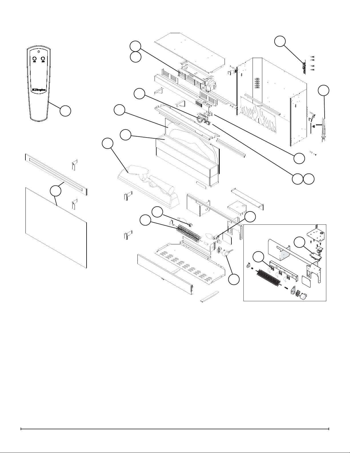
EXPLODED PARTS DIAGRAM: DF2426, DF2550, DFG2562, 6905050100-500
1. Remote Control ...................3000370500RP
2. Flicker Motor .....................2000210200RP
3. Heater Assembly (with cutout). . . . . . . . 2200491100RP
4. Thermostat ......................2300150100RP
5. Cutout ..........................2300270100RP
6. Light Assembly
Mod 0-A: 2 Socket Light Harness .....2500400500RP
Mod B: LED Light Assembly .........9600810100RP
7. Heater Switch ....................2800070700RP
8. 3-Position Switch. . . . . . . . . . . . . . . . . . 2800071100RP
9. Remote Control Receiver ...........3000380200RP
10. Terminal Block . . . . . . . . . . . . . . . . . . . . 4000150100RP
11. Power Cord . . . . . . . . . . . . . . . . . . . . . . 4100040900RP
12. Flicker Rod ......................5901110100RP
13. Partially Reective Glass - DF2426. . . . 5901410100RP
DF2550/DFG2562 ..........5901410200RP
14. Control Knob . . . . . . . . . . . . . . . . . . . . . 8801080100RP
15. DF2426SS Stainless Steel Trim Assembly
(comes with Front Glass) ...........1020230280RP
DF2426GB Gloss Black Trim Assembly
(comes with Front Glass)
...........1020230104RP
DF2550/DFG2562 Flat Black Trim Assembly
(comes with Front Glass)
...........1020230359RP
6905050400/6905050500 Silver Trim Assembly
(comes with Front Glass)
...........1020230478RP
16. DF2426/DF2550 Log Set Assembly ...0439970100RP
6905050400/0500 Tray. . . . . . . . . . . . . 0440400100RP
Glass Media
.....................1400070100RP
17. LED Driver Board .................3001170100RP
OEM Accessory
River Rocks . . . . . . . . . . . . . . . . . . . . . . . . . . . . . . DFS1314
6
16
2
3
4
5
9
10
8
7
13
14
12
15
11
1
16
Mod B
6
17
MOD 0-A
6 www.dimplex.com
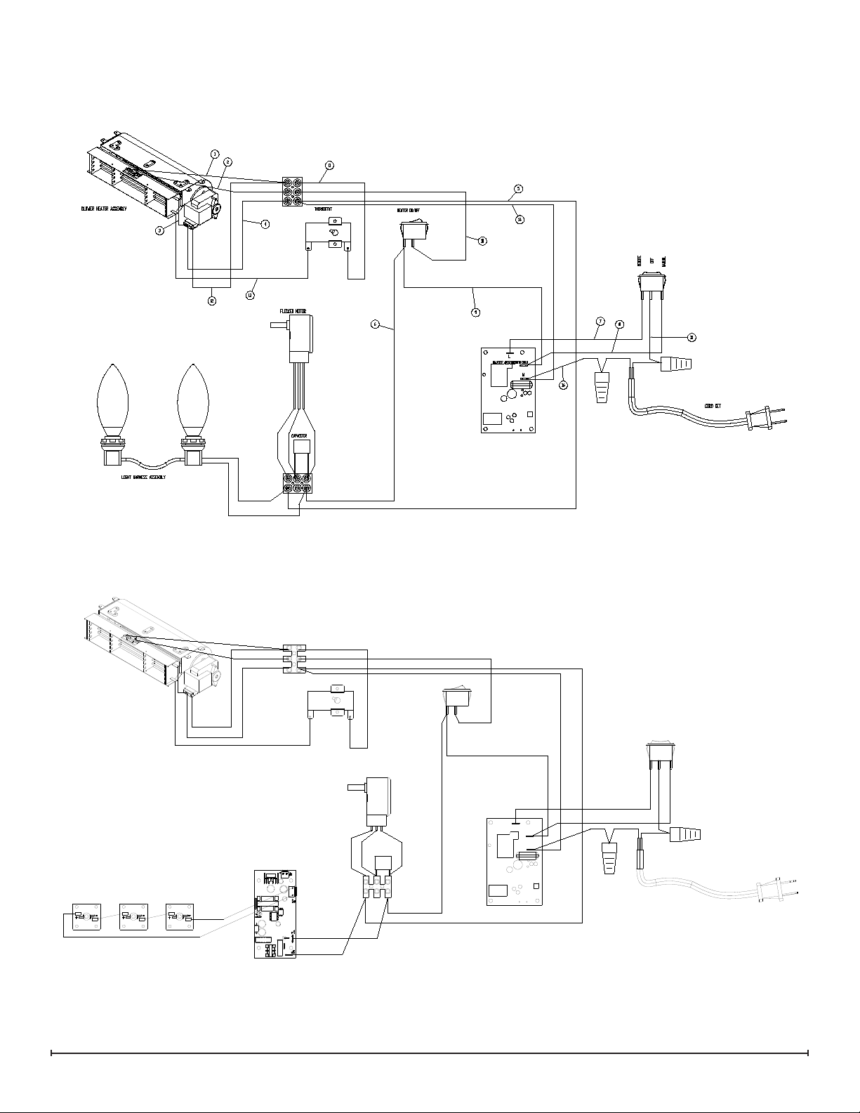
WIRING DIAGRAM: DF2426, DF2550, DFG2562, 6905050100-500
MOD 0-A
MOD B
LED DRIVER BOARD
MANUAL
CAPACITOR
HEATER ON/OFF
CORD SET
ON/OFF REMOTE
BLOWER HEATER ASSEMBLY
FLICKER MOTOR
THERMOSTAT
OFF
REMOTE
N
SWITCH OUPUT
L
LED LIGHT HARNESS
 Loading...