

Page 1

Master Time, Space, and Dimension
Owner’s Manual
Page 2
IMPORTANT SAFETY INFORMATION
WarnInG for your ProtectIon
reaD tHe foLLoWInG:
KEEP THESE INSTRUCTIONS
HEED ALL WARNINGS
FOLLOW ALL INSTRUCTIONS
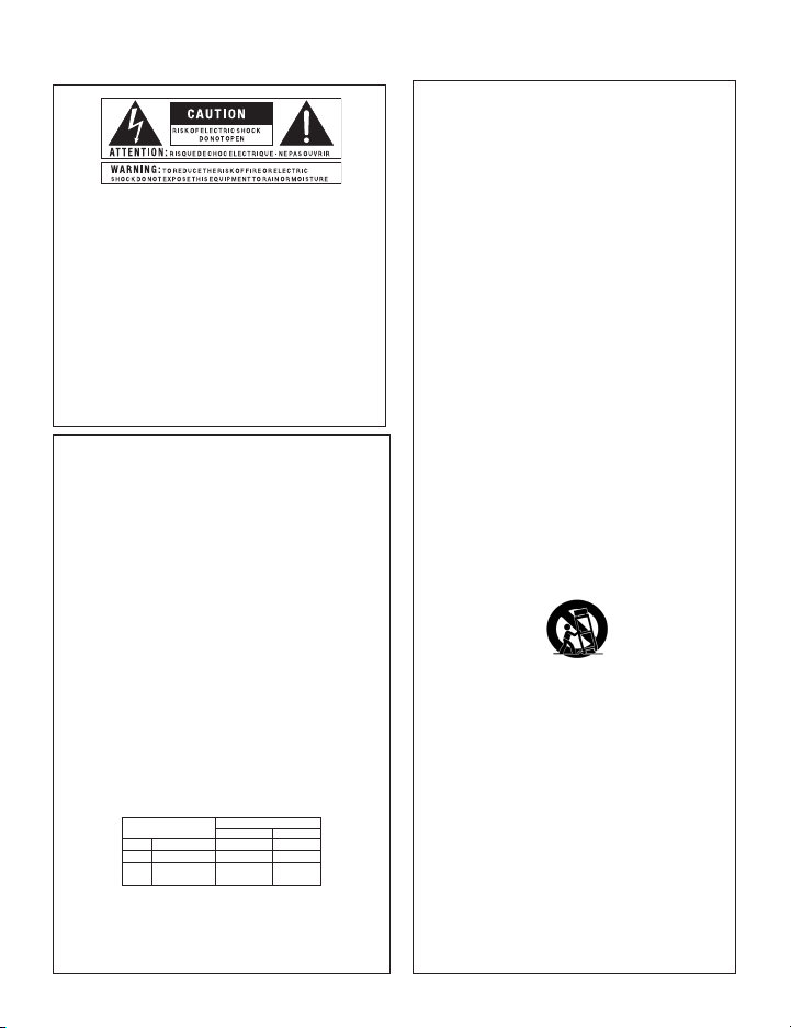
The symbols shown above are internationally accepted symbols that
warn of potential hazards with electrical products. The lightning flash
with arrowpoint in an equilateral triangle means that there are dangerous
voltages present within the unit. The exclamation point in an equilateral
triangle indicates that it is necessary for the user to refer to the owner’s
manual.
These symbols warn that there are no user ser viceable parts inside the
unit. Do not open the unit. Do not attempt to ser vice the unit yourself.
Refer all servicing to qualified personnel. Opening the chassis for any
reason will void the manufacturer’s warranty. Do not get the unit wet. If
liquid is spilled on the unit, shut it off immediately and take it to a dealer
for service. Disconnect the unit during storms to prevent damage.
Safety InStructIonS
NOTICE FOR CUSTOMERS IF Y OUR UNIT IS EQU IPPED WITH A P OWER CORD.
WARNING: THIS APPLIANCE SHALL BE CONNECTED TO A MAINS SOCKET OUTLET WITH A
PROTECTIVE EARTHING CONNECTION.
The core s in the mai ns lead are coloured i n accordanc e with the following co de:
GREEN and YELLOW - Earth BLUE - Neutral BROWN - Live
As colours of the cores in the mains lead of this appliance may not correspond with the
coloured markings identifying the terminals in your plug, proceed as follows:
•
The core which is coloured green and yellow must be connected to the terminal in the
plug marked with the letter E, or with the earth symbol, or coloured green, or green
and yellow.
•
The core which is coloured blue must be connected to the terminal marked N or coloured
black.
•
The core which is coloured brown must be connected to the terminal marked L or
coloured red.
This equipment may require the use of a different line cord, attachment plug, or both,
depending on the available power source at installation. If the attachment plug needs to
be changed, refer servicing to qualified service personnel who should refer to the table
below. The green/yellow wire shall be connected directly to the units chassis.
CONDUCTOR
L LIVE BROWN BLACK
N NEUTRAL BLUE WHITE
E EARTH GND
WARNING: If the ground is defeated, certain fault conditions in the unit or in the system
to which it is connected can result in full line voltage between chassis and earth ground.
Severe injury or death can then result if the chassis and earth ground are touched
simultaneously.
WIRE COLOR
Normal Alt
GREEN/
YEL
GREEN
THE APPARATUS SHALL NOT BE EXPOSED TO DRIPPING OR SPLASHING LIQUID
AND NO OBJECT FILLED WITH LIQUID, SUCH AS VASES, SHALL BE PLACED ON
THE APPARATUS
CLEAN ONLY WITH A DRY CLOTH.
DO NOT BLOCK ANY OF THE VENTILATION OPENINGS. INSTALL IN ACCORDANCE
WITH THE MANUFACTURER’S INSTRUCTIONS.
DO NOT INSTALL NEAR ANY HEAT SOURCES SUCH AS RADIATORS, HEAT REGISTERS,
STOVES, OR OTHER APPARATUS (INCLUDING AMPLIFIERS) THAT PRODUCE HEAT.
ONLY USE ATTACHMENTS/ACCESSORIES SPECIFIED BY THE MANUFACTURER.
UNPLUG THIS APPARATUS DURING LIGHTNING STORMS OR WHEN UNUSED FOR
LONG PERIODS OF TIME.
Do not defeat the safety purpose of the polarized or grounding-type plug. A polarized
plug has two blades with one wider than the other. A grounding type plug has two
blades and a third grounding prong. The wide blade or third prong are provided for
your safety. If the provided plug does not fit your outlet, consult an electrician for
replacement of the obsolete outlet.
Protect the power cord from being walked on or pinched particularly at plugs,
convenience receptacles, and the point where they exit from the apparatus.
Use only with the cart stand, tripod bracket, or table specified by the manufacture,
or sold with the appar atus. When a cart is used, use caution when moving the cart/
apparatus combination to avoid injur y from tip-over.
Refer all servicing to qualified service personnel. Servicing is required when the apparatus
has been damaged in any way, such as power-supply cord or plug is damaged, liquid
has been spilled or objects have fallen into the apparatus, the apparatus has been
exposed to rain or moisture, does not operate normally, or has been dropped.
POWER ON/OFF SWITCH: For products provided with a power switch, the power
switch DOES NOT break the connection from the mains.
MAINS DISCONNECT: The plug shall remain readily operable. For rack-mount or
installation where plug is not accessible, an all-pole mains switch with a contact
separation of at least 3 mm in each pole shall be incorporated into the electrical
installation of the rack or building.
FOR UNITS EQUIPPED WITH EXTERNALLY ACCESSIBLE FUSE RECEPTACLE: Replace
fuse with same type and rating only.
MULTIPLE-INPUT VOLTAGE: This equipment may require the use of a different line
cord, attachment plug, or both, depending on the available power source at installation.
Connect this equipment only to the power source indicated on the equipment rear
panel. To reduce the risk of fire or electric shock, refer servicing to qualified service
personnel or equivalent.
Page 3

If you want to dispose this product, do not mix it with general household waste. There is a
separate collection system for used electronic products in accordance with legislation that
requires proper treatment, recovery and recycling.
Private household in the 25 member states of the EU, in Switzerland and Norway may return their used
electronic products free of charge to designated collection facilities or to a retailer (if you purchase a similar
new one).
For Countries not mentioned above, please contact your local authorities for a correct method of disposal.
By doing so you will ensure that your disposed product undergoes the necessary treatment, recovery and
recycling and thus prevent potential negative effects on the environment and human health.
IMPORTANT SAFETY INFORMATION
eLectroMaGnetIc
coMPatIBILIty
This unit conforms to the Product Specifications noted on the
Declaration of Conformity. Operation is subject to the
following two conditions:
this device may not cause harmful •
interference, and
this device must accept any interference received, •
including interference that may cause undesired
operation.
Operation of this unit within significant
electromagnetic fields should be avoided.
use only shielded interconnecting cables.•
u.K. MaInS PLuG WarnInG
A molded mains plug that has been cut off from the cord
is unsafe. Discard the mains plug at a suitable disposal
facility.
NEVER UNDER ANY CIRCUMSTANCES
SHOULD YOU INSERT A DAMAGED OR
CUT MAINS PLUG INTO A 13 AMP POWER
SOCKET.
Do not use the mains plug without the fuse cover in
place. Replacement fuse covers can be obtained from
your local retailer. Replacement fuses are 13 amps and
MUST be ASTA approved to BS1362.
DecLaratIon of
conforMIty
Manufacturer’s Name: DigiTech
Manufacturer’s Address: 8760 S. Sandy Parkway
Sandy, Utah 84070, USA
declares that the product:
Product name: TimeBender
Product option: all (requires Class II power
adapter that conforms
to the requirements of
EN60065, EN60742, or
equivalent.)
conforms to the following Product Specifications:
Safety: IEC 60065 (7th ed. 2001)
EMC: EN 55013 (2001+A1)
EN 55020 (1998)
Supplementary Information:
The product herewith complies with the requirements of the
Low Voltage Directive 2006/95/EC and the EMC Directive
2004/108/EC.
Vice-President of Engineering – MI
8760 S. Sandy Parkway
Sandy, Utah 84070, USA
Date: February 24, 2009
European Contact: Your local Di giTech Sales and Se rvice Office or
Harman Music Group
8760 South Sandy Parkway
Sandy, Utah 84070, USA
Ph: (801) 566-8800
Fax: (801) 568-7583
®
TM
Page 4

Warranty
We at DigiTech® are very proud of our products and back up each one we sell with the
following warranty:
1. The warranty registration card must be mailed within ten days after purchase date to
validate this warranty, or you can register via our website (www.digitech.com).
2. DigiTech warrants this product, when used solely within the U.S., to be free from defects
in materials and workmanship under normal use and service.
3. DigiTech liability under this warranty is limited to repairing or replacing defective
materials that show evidence of defect, provided the product is returned to DigiTech
WITH RETURN AUTHORIZATION, where all parts and labor will be covered up to a
period of one year (this warranty is extended to a period of six years when the product has
been properly registered by mail or through our website). A Return Authorization number
may be obtained from DigiTech by telephone. The company shall not be liable for any
consequential damage as a result of the product’s use in any circuit or assembly.
4. Proof-of-purchase is considered to be the burden of the consumer.
5. DigiTech reserves the right to make changes in design, or make additions to, or
improvements upon this product without incurring any obligation to install the same on
products previously manufactured.
6. The consumer forfeits the benefits of this warranty if the product’s main assembly is
opened and tampered with by anyone other than a certified DigiTech technician or, if the
product is used with AC voltages outside of the range suggested by the manufacturer.
7. The foregoing is in lieu of all other warranties, expressed or implied, and DigiTech neither
assumes nor authorizes any person to assume any obligation or liability in connection
with the sale of this product. In no event shall DigiTech or its dealers be liable for special
or consequential damages or from any delay in the performance of this warranty due to
causes beyond their control.
NOTE: The information contained in this manual is subject to change at any time without
notification. Some information contained in this manual may also be inaccurate due to
undocumented changes in the product or operating system since this version of the manual was
completed. The information contained in this version of the owner’s manual supersedes all
previous versions.
Page 5

Congratulations!
Table of Contents
Introduction ...............................................................................................1
Included Items ...................................................................................1
Features ..............................................................................................2
Guided Tour - Front Panel ........................................................................3
Guided Tour - Rear Panel ..........................................................................8
Tutorial ......................................................................................................10
Make Connections .............................................................................10
Set Up the TimeBenderTM ..................................................................11
Create a Basic Digital Delay ..............................................................11
Try a Different Pattern .......................................................................11
Change the Multiplier Value ..............................................................12
Set the Key by Strumming a Chord ...................................................12
Set the Tempo by Strumming with Muted Strings ............................12
Set the Key and Tempo by Strumming .............................................. 12
Set the Repeat Pattern by Strumming (Smart Strum) ........................13
Add a Pitch-Shifted Voice ..................................................................13
Adjust the Repeats ............................................................................13
Change the Delay Type ......................................................................14
Add Modulation .................................................................................14
Store the Current Settings to a Memory Location .............................14
Load Settings from a Memory Location ............................................14
Using the Looper ...............................................................................14
Using an Expression Pedal ................................................................16
Using the Envelope Delay Type ........................................................17
Delay Types ...............................................................................................18
Digital ................................................................................................18
Analog ................................................................................................ 18
Moving Head Tape .............................................................................18
Variable Speed Tape ...........................................................................18
Page 6

Table of Contents
Dynamic Digital ................................................................................. 19
Dynamic Analog ................................................................................19
Dynamic Repeats ...............................................................................19
Time Warp ..........................................................................................19
Reverse ..............................................................................................20
Envelope ............................................................................................20
Looper ................................................................................................20
Voicings .....................................................................................................21
Scalic Voicings ...................................................................................21
Triad-Centered Voicings ...................................................................22
Fixed Shift (Chromatic) Voicings ......................................................22
Random Voicings ...............................................................................22
Time Patterns ............................................................................................23
Simple Delay .....................................................................................23
Dual Delay .........................................................................................23
Multi-tap Pattern Delay .....................................................................23
Root-Based Pattern Delay .................................................................. 24
Connection Diagrams ................................................................................26
Connection Diagrams ........................................................................26
Mono In/Mono Out ............................................................................26
Mono In/Stereo Out (Ping-Pong Delays) ..........................................27
Mono In/Stereo Out (Centered Delays) .............................................28
TimeBenderTM in an Effects Loop .....................................................29
TimeBender in an Effects Chain (Stereo In/Stereo Out) ...................30
Appendix ...................................................................................................31
Factory Reset .....................................................................................31
Troubleshooting .................................................................................31
Specifications ............................................................................................33
Page 7

Introduction
Congratulations and thank you for purchasing the DigiTech® TimeBender™ musical
delay!
The DigiTech TimeBender is a new kind of delay pedal. It completely rebuilds the
idea of delay and what it can add to your performance.
It has an entire pedalboard worth of different kinds of delays built right into it: Digital,
Analog, Variable Speed and Moving Head Tape, plus several more. And you can
control their repeat patterns by strumming your guitar. The delay repeat patterns will
imitate whatever pattern you strum (up to six delays in a single pattern). You can also
select from a long list of preset repeat patterns.
The TimeBender can also change the pitch of the repeats and keep them in the key
you’re playing in. The result can be a melodic hurricane of musical notes following
every note you play, all with the right rhythm and harmonies.
It’s incredibly powerful and it adds tremendous depth to your music, yet it’s simple to
control: it only has two footswitches. The best place to begin is the Tutorial section of
this manual on page 10. And once you get to know the TimeBender, there’s no limit to
the incredible musical delays you’ll be able to create.
Included Items
TimeBender
PS0913B Power Supply
This Manual
Registration Card
1
Page 8

Introduction
Features
Five seconds of true stereo delay.•
Selectable voicings, for musically intelligent arpeggios and harmony-based •
delays.
Set tempo, key, and even time patterns just by strumming your guitar.•
Strum Pattern allows you to easily create and save custom delay patterns on •
the fly.
Tempo Multiplier button lets you produce delays in between beats and makes •
complex patterns such as triplets much easier to configure.
Traditional delay sounds (Digital, Analog, Fixed Head Tape and Variable •
Speed Tape, Reverse) are easily selectable and ensure that this is the only
delay pedal you’ll need.
Fits in your pedal chain like any other delay.•
Built-in 20 second Looper lets you create and overdub loops on the fly.•
Harmony-shifted delays let you create new delay sounds in any key. •
Save your favorite sounds to four memory locations.•
Tone control gives you full control over the sound of your delays.•
Modulation control with three speed ranges can be used with all the delay •
types.
Envelope delay creates musically correct arpeggios as well as tempo-based •
rhythm-chopping effects.
Dynamic Delays “duck” the repeats while you play and leave the repeats •
when you stop.
Expression pedal input lets you morph between two saved settings for •
amazing new effects.
Optional FS3X footswitch input enables up and down memory changes.•
Supports both mono and stereo inputs and outputs, as well as full stereo •
effects including ping-pong, stereo modulation, and dual-delay lines.
2
Page 9

Guided Tour - Front Panel
PATTERN
DELAY TYPE DELAY TIME
VOICING
REPEATS MODULATIONTONE MULTIPLIER
ON
MIX
STORE
1
2 3 4 MEM
DRY
OFF
SLOW FAST
MEDIUM
BPMTAP REF
HOLD FOR
BPM
TOGGLE
DYNAMIC
ANALOG
DYNAMIC
DIGITAL
DYNAMIC
REPEATS
TIME WARP
VARIABLE
SPEED TAPE
MOVING
HEAD TAPE
ANALOG
DIGITAL
LOOPER
ENVELOPE
REVERSE
STRUM
TEMPO
1
3
7
9
10
13
14
16
1
17
1
2
4
5
15
6
12
11
8
Delay Type Knob 1.
The Delay Type knob selects the different delay types and styles. Each delay type
has a unique sound which is described in detail on page 18.
Delay Time Knob 2.
The Delay Time knob sets the length of the delay. The display shows the delay
time when you turn this knob.
Display3.
The display usually shows the current delay time (the time it takes for a repeat to
be heard). It shows this in either delay time or in beats per minute. For delay
time, the format is [S.MMM] where S is seconds, and MMM is milliseconds. For
beats per minute, the delay time is expressed in terms of quarter note beats per
minute, with a resolution of 1/10 beat.
3
Page 10

Guided Tour - Front Panel
When you turn the Voicing knob, the display shows the currently selected voicing.
If the Voicing knob is untouched for two seconds, the display goes back to showing
the current delay time. The display also shows the selected delay when you turn the
Delay Type knob.
When the Looper is selected, the display reads Loop. When recording starts, the
available loop time (shown in seconds) begins to count down in the display. When
the loop is playing back, the current playback position within the loop is shown
as a series of vertical bars moving across the display in proportion to the length of
the loop.
Voicing Knob 4.
The Voicing knob lets you change the pitch of the delayed signals (repeats) that
you hear. When the voicing is set to unison (U or U U), the TimeBenderTM creates
a traditional delay effect. But by changing the delay voicings, you have access
to a huge canvas of sonic possibilities like octave shifts and intelligent musical
intervals. Turn the Voicing knob by a single click to see the currently selected
voicing set. Turn it again to cycle through the other available voicing sets. The
voicings are described on page 21.
Mix Knob5.
The Mix knob controls the level of the delayed signal or Looper playback. Turn
it all the way down (counter-clockwise) to hear just your guitar and no delays. As
you turn the Mix knob up (clockwise), the delayed signal gets louder. For a 100%
wet mix (all delay, no input guitar signal), turn the Mix knob all the way up to the
black region marked DRY OFF. The display will briefly show d.OFFfor all delay
types except Reverse, Envelope, and Looper. To get the dry signal mixed back
in, turn the Mix knob counter clockwise until it is out of the DRY OFF region
(the display will briefly show d. On). For every delay type except Reverse and
Envelope, the Mix knob controls the level of the delays only – the input guitar
signal is the same undigitized signal you would hear if the TimeBender were
turned off. But when Reverse or Envelope are active, the input guitar signal level
gets reduced as you turn up the Mix knob, so you can adjust a wet/dry mix.
Memory Indicator LED6.
When the Memory Indicator LED is lit, you can step on the right footswitch to
advance to the next memory location. When the Memory Indicator LED is off,
you can use the right footswitch to set the tempo by tapping at the desired beat.
Holding down both footswitches at the same time turns the Memory Indicator
LED on or off.
4
Page 11

Guided Tour - Front Panel
Memory Location LEDs7.
The Memory Location LEDs indicate which memory location is currently
loaded. To make it easier to see at a glance which memory location is being
used, all LEDs up to and including the currently loaded location are illuminated.
When no memory LEDs are illuminated, no memory location is loaded, and the
TimeBenderTM is set exactly how the controls, LEDs, and (optional) expression
pedal indicate. When you load a memory location by stepping on the Tempo /
Memory footswitch, the settings stored in that location become active, and the
knob positions and displays may not match how the TimeBender sounds.
Store Button 8 .
If any changes are made to the knobs or buttons, the Store button’s LED lights
up. Press the Store button once and the current Memory Location LED flashes (or
the first Memory Location LED, if no memory location is loaded). Use the right
footswitch to select which memory location to use. Press the Store button a 2nd
time to store the changes into that memory location. After the store operation, this
memory location will now be active. To cancel the store procedure while the Store
LED is flashing, press the Delay On/Off footswitch or the Multiplier button.
Tempo LED 9.
The Tempo LED flashes at the quarter note reference delay time. If the Multiplier
is set to something other than the quarter note reference, the delay repeats will not
be heard in sync with the Tempo LED flash rate.
Pattern Knob10.
The Pattern knob selects the delay pattern that will be repeated at the selected
tempo (like single delay, dual delay, multi-tap, etc.). When the “Strum” setting is
chosen, you can hold down the right footswitch to strum out a time pattern. See
page 13 for more information on creating patterns.
Modulation Knob 11.
The Modulation knob lets you add chorusing to any delay type. There are three
ranges on the knob that correspond to the speed of the modulation that will be
applied. As the Modulation knob is turned through the first range, you’ll hear a
slow modulation with increasing depth. As you pass into the second range, the
modulation depth will drop to zero and then increase, but this time with a faster
modulation speed. The final range implements a very fast modulation.
5
Page 12

Guided Tour - Front Panel
When Time Warp is selected, the Modulation knob adds synchronized pitch
vibrato to the delay signal in three different sync ranges.
Multiplier Button12.
The Multiplier button changes the repeat rate by a fixed multiple or sub-multiple
of the quarter note reference delay time (up to a maximum of five seconds;
multiplying the reference delay time to more than five seconds pushes it out of
range, indicated by dashes ---- in the display). For example, if your current
reference delay time is set to 1 second, setting the tempo multiplier to the quarter
note value will cause the current pattern to be repeated every second. If you
change the tempo multiplier (by pressing the multiplier button) to the half note
setting, the pattern will repeat every two seconds. When the “triplet” eighth
note setting is selected, the pattern will repeat every 1/3 of a second. The tempo
multiplier also makes it easier to create off-beat delay patterns. For example, if
you use the dotted eighth note setting with a single delay, you can play on eight
note boundaries and get delays played back in between your own notes.
Note: Even though the tempo multiplier always changes the delay time, the
display will not reflect this if it is set to show BPM because BPM timing is always
reported in terms of quarter note beats. To switch between BPM display and time
display, press and hold the Multiplier button for one second.
Tempo/Memory Footswitch13.
The Tempo/Memory Footswitch’s function depends on the state of the Memory
Indicator LED. When the Memory Indicator LED is off, the footswitch can
be used to tap out a tempo that will be reflected in the display. Otherwise, the
footswitch advances to the next memory location each time it is pressed. See the
Memory Indicator LED description on page 4 for more information.
Additionally, this footswitch can be used to set several important delay effect
parameters using only your guitar. Pressing and holding the Tempo/Memory
footswitch activates the Smart Strum feature. With the Smart Strum feature,
you can do the following: strum a chord to set the scale used for voicings with
intelligent shifts, or strum at a steady beat to set the reference delay time. Also, if
the time pattern knob is set to “Strum”, you can strum a time pattern, as described
on page 13.
6
Page 13

Guided Tour - Front Panel
Delay On/Off Footswitch14.
The Delay On/Off footswitch turns the delay effect on and off. When the delay
is off, your guitar signal is never digitized, so your tone is preserved. If any
repeats are being heard when the delay is turned off, the repeats fade out instead
of silencing instantly. For all delay types except Envelope, Reverse, and Looper,
this footswitch can also be used to freeze the delay line so you can, for example,
solo over a repeating backing track. To do this, hold down the footswitch for one
second—the Delay Indicator LED turns yellow, the delays loop continuously, and
the input guitar signal stops feeding into the delay line. Step on the pedal again to
re-enable the feedback loop input and return the pedal to the “on” position.
When Looper is selected, press the Delay On/Off footswitch once to start recording a
loop; press it again to stop recording and begin loop playback. Step on it while a loop
is being played back to overdub your current guitar signal onto the existing loop.
Repeats Knob15.
The Repeats knob controls the amount of signal that is fed back into the delay lines.
When the Repeats knob is turned all the way down (counter-clockwise), you hear
one or very few repeats of the delay pattern. As you turn the Repeats knob up, the
pattern circulates more and more causing the delays to repeat for longer and longer
time periods. When Envelope is selected, the Repeats knob controls the shape of the
envelopes applied to the input guitar signal. In the leftmost position, the envelope
has a sharp onset and a rapid decay, giving the effect of a newly plucked note. As
the Repeats knob is turned up, the envelope shape changes. It first begins to shorten
until it becomes quite percussive, then becomes longer with a more level sustain
section. Towards the end of the range the envelope has an upward ramp with a quick
decay resulting in a reverse envelope sound.
On LED16.
When this LED is green, the delay effect is turned on. When the LED is yellow,
the delay signal is set to Infinite Repeat (no input signal is being added to the
delay line). When Looper is selected, the LED is red during recording, green
during playback, and yellow during overdub.
Tone Knob17.
The Tone knob alters the tonal characteristics of the delay signal. Although the
exact tonal change depends on the selected delay type, generally turning the knob
to the left creates a darker (bass) tone, and turning it to the right creates a brighter
(treble) tone. In the center position, no additional tone coloring (beyond what is
already part of the currently selected delay type) is applied. Hint: An easy way to
control the quality of the tape in the Tape delay is to turn down the Tone knob.
7
Page 14

9VAC
1300mA
POWER
1111 2222 5555 3333 4444 6666
Guided Tour - Rear Panel
Left (Mono) Input 1.
If you have separate left and right inputs, connect your left input to this jack. If
you’re using a mono input/stereo output configuration, connect to this input if
you want the delays to “ping-pong” between the right and left outputs (for delay
types with multiple taps).
Right Input 2.
If you have separate left and right inputs, connect your right input to this jack. If
you’re using a mono input/stereo output configuration, connect it to this input if
you want all delays (other than dual-delays) to be panned center.
Main Outputs3.
Connect the outputs to your amp or mixer. Use only the left output for mono, or
connect both for full stereo sound.
Footswitch Input4.
Connect an optional 3-button FS3X footswitch to this input to step through the
memory locations. On the FS3X, the right button moves you up one memory
location, and the center button moves you down one location. When Looper
8
Page 15

Guided Tour - Rear Panel
is selected, the left button takes you directly to overdubbing. Connect or
disconnect the optional FS3X footswitch only when the TimeBenderTM is turned
off.
Expression Pedal Input5.
Connect a mono (tip/sleeve) passive expression pedal to this input to morph
between two different delay settings. (Any volume pedal in the 100 kOhm – 500
kOhm range, with log taper, will work as well.) See page 16 for details on how
to use an expression pedal with the TimeBenderTM.
Power Supply Jack6.
Connect the PS0913B power supply here.
9
Page 16

Tutorial
9VAC
1300mA
POWER
Connect your guitar to the
TimeBender
TM
’s Left input.
Connect the TimeBender’s
Left output to your amp’s
input.
This section walks you through some basic functions and helps you get familiar with
the controls. It also gives you an idea of what the TimeBenderTM is capable of. This
Tutorial uses the Mono In/Mono Out setup, as shown below.
Make Connections
Before connecting the TimeBender, make sure that the power to your amplifier or
P.A. is off and that the TimeBender is powered on. There is no power switch on the
TimeBender. To turn the TimeBender on or off, connect or disconnect the included
PS0913B power supply from the Power Supply jack.
Connect your guitar to the Left (Mono) Input jack.1.
Make sure your amp’s volume is turned all the way down.2.
Connect the Left (Mono) output jack to your amp or other effects.3.
Turn on your amp.4.
Gradually increase your amp’s volume until you reach a comfortable listening 5.
level.
10
Page 17

Tutorial
Set Up the TimeBender
Before you begin the tutorial, follow these steps to set up the TimeBenderTM:
Make sure your guitar is in tune using a tuner set to A-440.1.
Set the right footswitch to advance the memory locations. To do this, step on 2.
both footswitches so that the Memory Indicator LED is lit.
Press and release the right footswitch until no Memory Location LED is lit.3.
Set the right footswitch to control delay tempo. To do this, step on both foot-4.
switches so that the Memory Indicator LED is not lit.
Make sure the delay time is shown in seconds (where the decimal point is be-5.
tween the 1st and 2nd digits in the display) rather than beats per minute (where
the decimal point is between the 3rd and 4th digits in the display). To switch
between beats per minute and seconds, press and hold the Multiplier button for
one second.
Turn the Modulation knob all the way down (counter-clockwise).6.
Turn the Pattern knob all the way down (counter-clockwise).7.
Turn the Voicing knob to the left until 8. U appears in the display.
Set the Tone knob to the 12 o’clock position.9.
Finally, make sure the multiplier is set to quarter notes. To do this, press and 10.
release the Multiplier button until the quarter note is selected.
TM
Create a Basic Digital Delay
Select Digital Delay by turning the Delay Type knob all the way to the left. 1.
“ ” will appear briefly in the display.
Adjust the Delay Time knob so that 2. 0.500 appears in the display.
Set the Repeats knob to the 9 o’clock position.3.
Set the Mix knob to the 12 o’clock position.4.
Press and release the Delay On/Off footswitch so the On LED lights up.5.
Play a single note. You should hear a simple delay.6.
Try a Different Pattern
Turn the Pattern knob one click to the right. 1. P2 will appear briefly in the display.
Play your guitar and note how the repeat pattern is different than before.2.
11
Page 18

Tutorial
Change the Multiplier Value
Press and release the Multiplier button one time, so the half note is selected. The 1.
delay time shown in the display should now be 1.000.
Play a single note. Notice how the repeats take twice as long as they did when 2.
the quarter note was selected.
Now press and release the Multiplier button twice, so the eighth note is selected. 3.
The delay time shown in the display should now be 0.250.
Play a single note. Notice how the repeats are twice as fast as they were when the 4.
quarter note was selected.
Set the Key by Strumming a Chord
Turn the Pattern knob to any pattern other than Strum.1.
Press and hold the right footswitch. The display briefly shows the current key, 2.
then goes blank.
While holding the right footswitch down, strum a G major chord. 3. G appears in
the display. The key is now set to G, and any scalic or triad-centered voicings
will create pitch-shifted repeats based on this key.
Note: The outputs are muted while setting the key.
Set the Tempo by Strumming with Muted Strings
Turn the Pattern knob to any pattern other than Strum.1.
Press and hold the right footswitch.2.
Mute the strings with your left hand (if you’re playing right-handed). That is, 3.
cover them with your fingers but don’t press them down to the fretboard.
Strum the tempo you want. Notice how the blue Tempo LED blinks in time with 4.
the tempo you’re strumming.
Release the right footswitch. 5.
Note: The outputs are muted while setting the tempo.
Set the Key and Tempo by Strumming
Press and hold the right footswitch.1.
Strum a G major chord at the tempo you want. Having more silence between 2.
strums will increase the accuracy of the tempo detection. Notice how the blue
12
Page 19

Tutorial
Tempo LED blinks in time with the tempo of your strumming, and the display
shows G. (Minor keys are indicated by a dash after the note in the display.)
Note: The outputs are muted while setting key and tempo by strumming.
Set the Repeat Pattern by Strumming (Smart Strum)
Turn the Time Pattern Knob to the last position to select the Strum pattern (1. Str).
Press and hold the right footswitch. The display briefly shows the currently 2.
stored key and flashes P while you hold down the footswitch.
Strum multi-tap time pattern. Your first strum marks the start of the delay pattern, 3.
and each subsequent strum automatically creates a delay (tap) at that time. You
can strum up to seven times in order to set all six delay taps. You can also set
a pattern by playing two or more repeats of the pattern while holding down the
footswitch. Whenever more than seven strums are detected, Smart Strum will
organize the strums into repeated groups and use this for the pattern.
Release the right footswitch. If a consistent pattern was detected, the display will 4.
briefly show Good. If a consistent pattern could not be found, the display will
briefly show ???? and the existing pattern will not be changed.
Note: When you set a repeat pattern with Smart Strum, you also set the tempo. The
tempo is the time between the first strum and the last strum in the resulting pattern.
The outputs are also muted when using Smart Strum.
Add a Pitch-Shifted Voice
Turn the Voicing knob one click to the right. The current voicing pattern will ap-1.
pear briefly in the display. Using this tutorial, it should read U U.
Once the display shows the delay time again (2. 0.500 for instance), turn the Voicing knob four clicks to the right. The display should briefly show U H, then go
back to showing the delay time.
Play a single note in the key of G major. Notice how some of the repeats are 3.
slightly higher than the original note, and how they’re in harmony.
Adjust the Repeats
Turn the Repeats knob to the 1 o’clock position.1.
Play a single note and notice how much longer the repeats last.2.
13
Page 20

Tutorial
Change the Delay Type
Turn the Delay Type knob to Analog.1.
Play a single note and notice how the repeats gradually decrease in fidelity.2.
Add Modulation
Turn the Modulation knob to the 12 o’clock position.1.
Play your guitar and listen to the chorus-like effect applied to the repeats.2.
Store the Current Settings to a Memory Location
Press the Store button. The currently active (or first available) Memory Location 1.
LED flashes.
Press and release the right footswitch until the Memory Location 1 LED is lit. 2.
Press the Store button again. The TimeBender3.
Memory Location 1.
Note: You can abort the store procedure by pressing the Delay On/Off footswitch.
Load Settings from a Memory Location
Set the Tempo/Memory footswitch to select memory locations. To do this, press 1.
both footswitches until the Memory Indicator LED is lit.
Press and release the right footswitch to select a memory location, indicated by 2.
the Memory Location LEDs. Note that when location 2 is selected, LEDs 1 and 2
are lit; when location 3 is selected, LEDs 1, 2, and 3 are lit, and so on.
Settings load automatically when a memory location is selected.3.
Using the Looper
The TimeBender’s Looper lets you record, play back, and overdub loops up to 20 seconds long. Enable the Looper by turning the Delay Type knob to the Looper position.
Note that the Looper sums stereo input signals to mono, and outputs a mono signal
only.
The voicing still works when the Looper is active, so you can do things like record a
bass line with the voicing set to an octave down (8L), and then set the voicing to unison and play over the looped bass line. Also, with an expression pedal, you can store a
unison voicing in the toe position and an octave down in the heel position, and switch
between your “bass” and guitar on the fly.
TM
’s current settings are stored to
14
Page 21

Tutorial
When recording your loop, you hear what is actually being recorded. The only effect
that you hear before recording is the pitch shift (so you can record a bass line and then
a regular guitar line, for example). That means you won’t hear the mix, modulation
and tone effects until the loop is being played back since they are applied after recording. It also means you can adjust these effects during playback to change the sound of
the loop.
The following controls are active when Looper is selected:
Mix Knob
Tone Knob
Modulation
Knob
Store Button
Left
Footswitch
Right
Footswitch
Activating the Looper
When you first activate the Looper (either by recalling a memory location in which
the Looper was previously stored, or by turning the Delay Type knob to the Looper
Controls the playback level of the looped audio.
Controls the tone of the loop. In the center position the tone will
match what was recorded.
Adds modulation effects to the looped audio.
Stores the current Mix, Tone, and Modulation knob settings into
a memory location. When this memory location is recalled, the
TimeBenderTM will activate the Looper with these settings. You can
only store a Looper preset when a loop is not playing.
When the Looper is active, the left footswitch controls Record,
Play, and Overdub functions (see below).
When the Looper is active, the right footswitch controls Stop and
Clear functions (described on the next page). Note that when the
Memory Indicator LED is lit and there is no loop in memory, the
right footswitch will maintain its memory advance function so you
can move through memory locations in the usual way. Whenever a
loop is recorded, the right footswitch won’t step through memory
locations or set the tempo, and you can’t press both footswitches
to turn the Memory Indicator LED on or off. When the loop is
cleared, you can do those things again.
15
Page 22

Tutorial
position), the display will read Loop and the loop memory will be cleared.
Recording a Loop
To begin recording a loop, start playing your guitar as you press and release the left
footswitch. The display will begin to count down the available recording time, and the
On LED will turn red. As you finish your loop, press and release left footswitch again.
The On LED will turn green and the loop will immediately begin to play back at the
current mix level. The TimeBenderTM automatically adjusts the starting and ending
loop points to match them as closely as possible. This makes it extremely easy to get
smoothly transitioning loops on the first try.
Stopping and Starting a Loop
To temporarily stop a loop from playing, press and release the right footswitch. The
On LED will turn off. You can restart the loop by pressing and releasing the left
footswitch. When the loop is playing back, the display will show the position of playback within the loop with a progress bar.
Overdubbing
Whenever a loop is playing, you can press and release the left footswitch to start
overdubbing. In this case, the On LED will change to yellow, and your playing will be
added to the current loop without replacing the existing audio. In this way, complex
loops can be built up successively.
Clearing a Loop
To clear the loop memory, stop the loop playback, then press and hold down the
right footswitch for two seconds. The Delay On LED blinks twice and the memory is
cleared.
Using an Expression Pedal
Using an expression pedal with the TimeBender is an easy way to unlock a whole
new set of stunning time-varying delay effects. An expression pedal lets you smoothly
morph between different settings for a given delay type, voicing, and time pattern allowing control over parameters such as delay time, tone, repeats, and modulation.
To use your expression pedal with the TimeBender:
Make sure no Memory Location LED is lit (see Set Up the TimeBender on page 11).1.
16
Page 23

Tutorial
Plug your expression pedal’s standard 1/4” connector into the Expression Pedal 2.
input on the back of the TimeBenderTM Delay.
Set the expression pedal to the minimum (heel) position.3.
Adjust the controls on the TimeBender to get a starting sound that you like.4.
Step forward on the expression pedal to put it into the maximum (toe) position. 5.
Adjust one or more of the delay time, voicing, mix, tone, repeats, modulation,
tempo multiplier, pattern, and key to get the sound that you like.
Move the pedal from the heel to the toe position while you’re playing and listen 6.
to the delay blend between your two settings.
When you store your changes to a memory location, both the heel and toe settings are
stored. If you don’t have an expression pedal connected when that memory location
is loaded, you’ll hear the toe position setting. To restore your expression pedal’s heel
and toe positions to match what the TimeBender controls are showing, simply step
through the memory locations until no memory location is selected; the expression
pedal’s heel and toe positions will now be reset. You can also unplug the expression
pedal and plug it back in to accomplish the same thing.
Using the Envelope Delay Type
When you use Envelope, you might notice that a short note won’t produce any audible
delays. That’s because Envelope creates delays using a completely different approach
than the other delay types. Instead of playing back a delayed version of your input
signal, Envelope “slices” up the current signal using configurable envelope shapes,
and then plays these slices back at the delay times defined by your current pattern. If
you’ve set voicings other than unison, these slices will be pitch shifted as well. Envelope works best with effects that have long sustains, like most distortion effects.
Changing Envelope Shapes
When the Envelope delay type is selected, the Repeats knob controls the shape of the
envelopes applied to the input guitar signal. In the leftmost position, the envelope
has a sharp onset and a rapid decay, giving the effect of a newly plucked note. As the
Repeats knob is turned up, the envelope shape changes. It first begins to shorten until
it becomes quite percussive, then becomes longer with a more level sustain section.
Towards the end of the range the envelope has an upward ramp with a quick decay
resulting in a reverse envelope sound.
17
Page 24

Delay Types
The TimeBenderTM includes 11 different delay types. Some recreate classic delays
that have remained popular for decades, while others (like Dynamic Repeats and the
TimeBender’s unique Envelope) are totally new, ready for you to try them out for the
first time.
Digital (1. )
The Digital delay provides a clean digital sound and a flat frequency response
with the tone knob at the 12 o’clock position. A limiter in the feedback path
prevents clipping and keeps the sound clean even when the Repeat knob is
turned up high. When you change the delay time in Digital delay, you’ll notice
that the old delay fades out while the new delay fades in—so the pitch of your
delayed signal remains constant.
Analog (2. Ana)
The Analog delay is based on the solid-state “bucket brigade” delays of
the 1970s. When the tone knob is at 12 o’clock, you’ll hear the substantial
high-frequency roll-off characteristic of these devices. The feedback path
includes a saturator that will introduce some distortion when the feedback signal
becomes large. When changing the delay time, you’ll notice the delay “slides” to
the new value resulting in a pitch shifted signal while the delay is moving.
Moving Head Tape (3. tAp1)
The Moving Head Tape delay is based on early (tube-based) systems that had
movable playback tape heads. Like the fixed head tape delay, the Moving Head
Tape delay also has saturation in the feedback loop and a characteristic high
frequency and low frequency roll-off. There is also a mid-boost sound across the
tone range common in tube-based systems. When changing delay time, you’ll
hear the sound of a moving tape head rather than the sound of changing the tape
speed—the pitch shift amount will depend on the size of the delay change.
18
Variable Speed Tape (4. tap2)
The Variable Speed Tape delay is based on early tape delays, in which the
delay was controlled by changing the speed of the tape. With the Tone knob
at 12 o’clock, you’ll hear both high frequency and low frequency roll-off. The
feedback path contains a saturator that mimics the saturation characteristics of
Page 25

Delay Types
physical tape. When changing delay time, you’ll hear the pitch of the delayed
signal change in exactly the same way as if you had changed the speed of a real
tape recorder—the pitch shift amount will depend on the difference between the
speed that the delayed signal was recorded at and the new speed. Note that the
amount of time required to move from one delay to another (and for the pitch
to return to normal) is equal to the amount of time it takes for the tape to move
from the record head to the fixed-playback head. As a result, moving from a
short delay to large delay will take much longer than moving from a large delay
to a short delay since in the first case, you need to slow the tape down.
Dynamic Digital (5 . )
The Dynamic Digital delay type has built-in output “ducking”. Output ducking
automatically reduces the level of the delay effect while the input signal is
loud. When the input signal decays in volume, the delay effect rises in volume
resulting in a very dynamic sound.
Dynamic Analog6. (dana)
The Dynamic Analog delay type includes the same automatic ducking algorithm
as Dynamic Digital, but applies this to an analog delay.
Dynamic Repeats (7. drep)
The Dynamic Repeats delay type is totally new, and combines a Variable Speed
Tape delay with a new method of ducking called “feedback ducking”. Perfect
for large feedback levels, feedback ducking not only lowers the output level
while your playing is loud, but it also reduces the level of the signal going into
the feedback loop. This keeps the feedback loop from getting overly saturated
while you are playing, and means that the first delay sounds that become audible
will be clean.
Time Warp (8. 7i)
Time Warp is similar to the Analog delay, except that the modulations are
synchronized with the delay time and the depth can be much more extreme,
varying by hundreds of milliseconds.
19
Page 26

Delay Types
Reverse (9. re)
The Reverse delay type records the input signal in “chunks” with a length equal
to the current delay time setting, and then plays these sound segments back
in reverse. Unlike other reverse effects in which the chunks are arbitrary, the
TimeBenderTM starts chunks at note onsets where possible in order to avoid
having notes cross chunk boundaries. When using Reverse, the Mix knob starts
to attenuate (reduce) the dry signal when you turn the knob up, so you can
adjust the wet/dry mix.
Envelope10. (en)
The Envelope delay type creates delayed versions of the input signal using a
completely different approach than the other delays. As an input signal is being
played, equal duration “slices” of the current signal are played back with a
particular voicing (as specified by the voicing encoder). The Repeats knob can
be used to alter the shape of each slice; for example, at the maximum position,
a reverse envelope shape is created having a slow attack and very quick decay.
When using Envelope, the Mix knob starts to attenuate (reduce) the dry signal
when you turn the knob up, so you can adjust the wet/dry mix.
Looper (11. Loop)
The Looper lets you record, overdub, start and stop loops. What makes this
Looper special is the fact that it analyzes your start and stop loop points and
automatically adjusts these in order to get the cleanest loop possible. This makes
it much easier to set up a loop because you don’t need to be nearly as accurate
as with traditional looper pedals. See page 14 for a detailed description of how
to use the Looper.
20
Page 27

Voicings
Voicings (Pitch-shifted Repeats)
One of the most exciting features of the TimeBenderTM is its ability to change the pitch
of the delayed signals. When the voicing is set to Unison (U), the delayed signal has
the same pitch as the guitar input, just like with traditional delay pedals. But with the
TimeBender, you can change the delays’ pitch to one or two “voicings” that relate to
the original note.
There are three main types of voicings: scalic, triad-centered, and fixed shift (chromatic). These are described in the tables below, but you may find it easier to experiment
with the TimeBender itself by trying different voicings (turn the Voicing knob) while
you play. Note that scalic and triad-centered voicings sound best when you play in the
key the TimeBender is set to (see page 12 for more on setting the key by strumming).
Scalic Voicings
Display Description
Input is shifted down by 2 octaves.
2o
Input is shifted down by 1 octave.
8L
Input is shifted to the 7th scale tone down.
7L
Input is shifted to the 6th scale tone down.
6L
Input is shifted to the 5th scale tone down.
5L
Input is shifted to the 4th scale tone down.
4L
Input is shifted to the 3rd scale tone down.
3L
Input is shifted to the 2nd scale tone down.
2L
Input is shifted to the 2nd scale tone up.
2H
Input is shifted to the 3rd scale tone up.
3H
Input is shifted to the 4th scale tone up.
4H
Input is shifted to the 5th scale tone up.
5H
Input is shifted to the 6th scale tone up.
6H
Input is shifted to the 7th scale tone up.
7H
Input is shifted up by an octave.
8H
21
Page 28

Voicings
Triad-Centered Voicings
Note: the triad-centered voicings are very similar to the scalic voicings shown on
the previous page, but with additional voicings listed below.
Display Description
Same as Scalic 6L except for the 5th of the scale which is shifted to the root.
LL
Same as Scalic 3L except for the root of the scale which is shifted to the 5th.
L
Same as Scalic 3H except for the 5th of the scale which is shifted to the root.
H
Same as Scalic 6H except for the root of the scale which is shifted to the 5th.
HH
Fixed Shift (Chromatic) Voicings
Display Description
-12, -11, … -1
1, 2, ... 24
Random Voicings (Envelope delay type only)
Display Description (Randomly applies the pitch shifts shown.)
rnd1
rnd2
rnd3
rnd4
rnd5
rnd6
rnd7
rnd8
8L LL L U H HH 8L
8L 5L 3L U 3H 5H 8H
8L -7 -5 U 5 7 8H
2o 8L U 8H 24
8L U 8H
4L 3L 2L U 2H 3H 4H
3L 2L U 2H 3H
8L 6L 5L 4L 2L U 3H 4H 5H 7H
Input is shifted down by the indicated number of semitones.
Input is shifted up by the indicated number of semitones.
22
Page 29

Time Patterns
Time Patterns
The TimeBenderTM includes several ready-made delay patterns you can choose with
the Pattern knob. They’re described here and in the table that follows, but you may
find it easier to sit down and listen to each one while using the TimeBender.
Each pattern has one or more “taps” where the delays occur, represented in the pattern
symbols by a vertical line. Each tap happens at a certain “chronological distance”
from the original note, described in the table below as a percentage of the total pattern’s length of time. Each tap is also panned (left, center, or right), and each tap has a
voice assigned to it.
There are four types of delay patterns: Simple Delays, Dual Delays, Multi-tap Pattern
Delays, and Root-Based Pattern Delays. Each type is described below. With all these
delay patterns, the TimeBenderTM can be used as a traditional delay, where the input
is delayed and played back unshifted, or in combination with pitch shifting (using the
Voicing knob), where the input signal is shifted before being delayed.
Simple Delay
The Simple Delay has one tap and just repeats whatever you’re playing. As the Repeats knob is turned up, you’ll hear more and more repeats until the signal dies out.
Dual Delay
A Dual Delay is really just two simple delay lines that can be independently configured. So you can have different repeat rates for each line. When using a stereo setup,
these lines are hard panned to the left and right channels. The TimeBender includes
three dual delay configurations in which the left channel repeat rate can be 1/2, 3/4, or
1/3 of the right channel delay which is controlled by the Delay Time knob.
Multi-tap Pattern Delay
A Multi-tap Pattern Delay is a delay line with more than one tap, resulting in
a more complex delay effect. The TimeBender includes two different multi-tap patterns: three-tap and six-tap.
23
Page 30

Time Patterns
Root-Based Pattern Delay
The Root-Based Pattern delay is a new concept that, when combined with the TimeBenderTM’s pitch shifting abilities, can create a wide variety of new sounds. Unlike
Multi-tap Pattern delays, every repetition in a root-based pattern begins with the original unshifted note that you played. You always hear this unshifted note repeat at the
specified delay time, followed by the rest of the notes in the pattern. The pattern gets
its name from the fact that it is commonly used for arpeggiation. For example, with
3H and 5H voicings, playing a note with a root-based pattern will result in a musically
intelligent arpeggio starting with the note you played. As you turn up the Repeats
knob, the arpeggiation will repeat over a longer time. And because of the root-based
nature of the pattern, you’ll hear the root of the arpeggio during each repetition.
Time Patterns
Pattern Symbol Number
of Taps
P1
Description
1 Simple Delay
Tap 1: Delay = 100%, Pan = Center, Voice = V1
24
P2
P3
P4
P5
2 Dual Delay (1/2, 1)
Tap 1 : Delay = 50%, Pan = Left, Voice = V1
Tap 2 : Delay = 100% Pan = Right, Voice = V2
2 Dual Delay (3/4, 1)
Tap 1 : Delay = 75%, Pan = Left, Voice = V1
Tap 2 : Delay = 100% Pan = Right, Voice = V2
2 Dual Delay (1/3, 1)
Tap 1 : Delay = 33%, Pan = Left, Voice = V1
Tap 2 : Delay = 100% Pan = Right, Voice = V2
1 Root-Based Pattern Delay (2/4 time)
Tap 1 : Delay = 50% Pan = Left, Voice = V1
Page 31

STRUM
Time Patterns
Pattern Symbol Number
of Taps
P6
P7
P8
P9
P10
Str
2 Root-Based Pattern Delay (3/4 time)
3 Root-Based Pattern Delay (4/4 time)
3 Root-Based Pattern Delay (4/4 swing time)
3 Multi-Tap Pattern Delay
6 Multi-Tap Pattern Delay
1-6 Pattern set by holding down the right footswitch
Description
Tap 1 : Delay = 33% Pan = Left, Voice = V1
Tap 2 : Delay = 66% Pan = Right, Voice = V2
Tap 1 : Delay = 25% Pan = Left, Voice = V1
Tap 2 : Delay = 50% Pan = Right, Voice = V2
Tap 3 : Delay = 75% Pan = Left, Voice = V1
Tap 1 : Delay = 33% Pan = Left, Voice = V1
Tap 2 : Delay = 50% Pan = Right, Voice = V2
Tap 3 : Delay = 83% Pan = Left, Voice = V1
Tap 1 : Delay = 37.5% Pan = Left, Voice = V1
Tap 2 : Delay = 70% Pan = Right, Voice = V2
Tap 3 : Delay = 100% Pan = Left, Voice = V1
Tap 1 : Delay = 16.6% Pan = Left, Voice = V1
Tap 2 : Delay = 33% Pan = Right, Voice = V2
Tap 3 : Delay = 50% Pan = Left, Voice = V1
Tap 4 : Delay = 66% Pan = Right, Voice = V2
Tap 5 : Delay = 83.3% Pan = Left, Voice = V1
Tap 6 : Delay = 100% Pan = Right, Voice = V2
(when Looper is not selected) and strumming the
pattern, up to six taps after the initial strum.
25
Page 32

9VAC
1300mA
POWER
Connect your guitar to the
TimeBender
TM
’s Left input.
Connect the TimeBender’s
Left output to your amp’s
input.
Optional FS3X footswitch.
Optional expression pedal.
Connection Diagrams
Connection Diagrams
The following diagrams show different ways of hooking up your TimeBenderTM.
Mono In/Mono Out
26
Page 33

9VAC
1300mA
POWER
Connect your guitar to the
TimeBender
TM
’s Left input.
Connect the TimeBender’s
stereo outputs to two amps
or two channels on a mixer.
Connection Diagrams
Mono In/Stereo Out (Ping-Pong Delays)
27
Page 34

9VAC
1300mA
POWER
Connect your guitar to the
TimeBender
TM
’s Right input.
Connect the TimeBender’s
stereo outputs to two amps
or two channels on a mixer.
Connection Diagrams
Mono In/Stereo Out (Centered Delays)
28
Page 35

Connection Diagrams
9VAC
1300mA
POWER
Connect your guitar to your
amp’s input.
Connect your amp’s effects
send to the TimeBender™’s
Left input.
Connect the TimeBender’s
Left output to your amp’s
effects return.
TimeBender™ in an Effects Loop
29
Page 36

9VAC
1300mA
POWER
Connect your guitar to your
effects chain input.
WAH
OVERDRIVE
DI GI TEC H®
WH AM MY
CHORUS/FX
(POST)
REVERB
Connection Diagrams
TimeBenderTM in an Effects Chain (Stereo In/Stereo Out)
30
Page 37

Appendix
Factory Reset
The Factory Reset procedure replaces all the memory locations with their
default settings as shipped from the factory.
Warning: Performing this procedure erases any changes you have made to the
memory locations!
Press and hold the Store button for three seconds. All the Memory 1.
Location LEDs flash and the display reads FAC.
Press and hold the Store button for three seconds again to perform the 2.
factory reset, or press the left footswitch or the Multiplier button to cancel.
Troubleshooting
Q: The TimeBenderTM isn’t doing what the controls say it should be doing.
A: You might have a memory location selected, which means the TimeBender has
loaded the settings stored to that memory location (regardless of what the knobs
and LEDs currently show). Also, if you have an expression pedal plugged in, the
expression pedal will morph between its settings for the heel position and toe
position. To get the TimeBender back to what the controls show, make sure the
Memory Indicator LED is lit (step on both footswitches if it isn’t), then press
and release the right footswitch until no Memory Location LED is lit. If you’re
using an expression pedal, unplug it when no Memory Location LED is lit to be
sure the knobs reflect the true state of the TimeBender.
Q: When I strum a tempo or pattern, the key sometimes changes unexpectedly.
A: Distortion pedals with extreme settings can boost hum and other noise that
might be interpreted as a note. Try turning off any effects and keep your strings
completely muted when strumming tempo and patterns.
Q: Why do I get a flashing P when I am trying to strum a tempo?
A: You may have Strum selected on the Pattern knob, or a memory location is
loaded with the Strum pattern saved to it. If you are using an expression pedal,
31
Page 38

Appendix
Specifications
the Strum pattern may have been saved to the current heel or toe position. To
get the TimeBenderTM back to what the controls show, make sure the Memory
Indicator LED is lit (step on both footswitches if it isn’t), then press and release
the right footswitch until no Memory Location LED is lit. If you’re using an
expression pedal, unplug it when no Memory Location LED is lit to be sure the
knobs reflect the true state of the TimeBender.
Q: The output keeps getting louder and louder!
A: Maybe the Repeats knob is set too high (or a memory location is loaded where
the Repeats knob was saved at a very high setting). To get the TimeBender back
to what the controls show, make sure the Memory Indicator LED is lit (step on
both footswitches if it isn’t), then press and release the right footswitch until
no Memory Location LED is lit. If you’re using an expression pedal, unplug it
when no Memory Location LED is lit to be sure the knobs reflect the true state
of the TimeBender. Then turn down the Repeats knob.
Q: The tempo LED is flashing with a different timing than the delay time shown on
the display.
A: When the delay time is shown in seconds (as opposed to BPM), the display only
matches the tempo LED when the Multiplier button is set to the quarter note
position.
Tips and Tricks
If you turn the Voicing knob one click, the display shows the current voicing •
without changing it.
32
Stepping on the right footswitch while muting your guitar shows you the current •
key.
Use the LED with the Envelope delay type to synchronize your playing with the •
pattern.
Try using the • 8L voicing with the Looper to make your guitar sound like a bass
when recording your loop.
Page 39

Specifications
Input/Output Connections
Left (Mono) and Right Inputs 1/4” mono (unbalanced, tip/sleeve)
Maximum Input Level: +6 dBu
Input Impedance: 1 MW
Left (Mono) and Right Outputs 1/4” mono (unbalanced, tip/sleeve)
Nominal Output Level: +12 dBu
Output Impedance: 1 kW
Footswitch 1/4” (tip/ring/sleeve)
Expression Pedal 1/4” (tip/sleeve). Recommend passive expression
(volume) pedal in the 100 kW to 500 kW range.
A/D Performance
Sample Rate Frequency 44.1 kHz
Bit Depth 24-bit Processing
Memory Capacity
Delay Time Up to 5 seconds of true stereo delay
Looper Up to 20 seconds (mono)
Power
US and Canada: 120 VAC, 60 Hz Adapter: PS0913B - 120
Japan: 100 VAC, 50/60 Hz Adapter: PS0913B - 100
Europe: 230 VAC, 50 Hz Adapter: PS0913B - 230
UK: 240 VAC, 50 Hz Adapter: PS0913B - 240
Australia: 240 VAC, 50 Hz Adapter: PS0913B - 240-AU
Power Input: 9 VAC 1.3 A
Power Consumption: 7 Watts
General
Dimensions: 6.7” Width x 5.6” Length x 2.6” Height
Weight: 2.88 lbs
DigiTech® engineers are constantly working to improve the quality of our products.
Specifications are therefore subject to change without notice.
33
Page 40

DigiTech®
8760 South Sandy Parkway
Sandy, Utah 84070
PH (801) 566-8800
FAX (801) 566-7005
www.digitech.com
TimeBenderTM Owner’s Manual 18-0686-A
Printed in the USA 3I2009
DigiTech is a registered trademarks of Harman International.
musIQ® is a registered trademark of 3dB Research Ltd.
©2009 Harman International Industries, Incorporated. All rights reserved
 Loading...