

Page 1
RP360
RP360 XP
GUITAR MULTI-EFFECTS PROCESSORS
OWNER’S MANUAL
Page 2
COMPLIANCE & SAFETY INSTRUCTIONS
WARNING FOR YOUR PROTECTION READ THE FOLLOWING:
The symbols shown above are internationally accepted symbols that warn of potential hazards
with electrical products. The lightning flash with
arrowpoint in an equilateral triangle means that
there are dangerous voltages present within the
unit. The exclamation point in an equilateral triangle indicates that it is necessary for the user to
refer to the owner’s manual.
These symbols warn that there are no user serviceable parts inside the unit. Do not open the
unit. Do not attempt to service the unit yourself. Refer all servicing to qualified personnel.
Opening the chassis for any reason will void the
manufacturer’s warranty. Do not get the unit
wet. If liquid is spilled on the unit, shut it off
immediately and take it to a dealer for service.
Disconnect the unit during storms to prevent
damage.
The following is indicative of
low altitude use; do not use this
product above 2000m.
ELECTROMAGNETIC
COMPATIBILITY
This device complies with part 15 of the FCC
Rules and the Product Specifications noted on
the Declaration of Conformity. Operation
is subject to the following two conditions:
• this device may not cause harmful
interference, and
• this device must accept any interference
received, including interference that may
cause undesired operation.
Operation of this unit within significant
electromagnetic fields should be avoided.
• use only shielded interconnecting cables.
KEEP THESE INSTRUCTIONS
HEED ALL WARNINGS
FOLLOW ALL INSTRUCTIONS
The apparatus shall not be exposed
to dripping or splashing liquid and no
object filled with liquid, such as vases,
shall be placed on the apparatus.
CLEAN ONLY WITH A DRY CLOTH.
FOR INDOOR USE ONLY.
DO NOT BLOCK ANY OF THE
VENTILATION OPENINGS. INSTALL
IN ACCORDANCE WITH THE
MANUFACTURER’S INSTRUCTIONS.
DO NOT INSTALL NEAR ANY HEAT
SOURCES SUCH AS RADIATORS, HEAT
REGISTERS, STOVES, OR OTHER
APPARATUS (INCLUDING AMPLIFIERS)
THAT PRODUCE HEAT.
ONLY USE ATTACHMENTS/ACCESSORIES
SPECIFIED BY THE MANUFACTURER.
UNPLUG THIS APPARATUS DURING
LIGHTNING STORMS OR WHEN UNUSED
FOR LONG PERIODS OF TIME.
Do not defeat the safety purpose of
the polarized or grounding-type plug.
A polarized plug has two blades with
one wider than the other. A grounding
type plug has two blades and a third
grounding prong. The wide blade
or third prong are provided for your
safety. If the provided plug does not
fit your outlet, consult an electrician for
replacement of the obsolete outlet.
Protect the power cord from being
walked on or pinched particularly at
plugs, convenience receptacles, and
the point where they exit from the
apparatus.
Use only with the cart stand, tripod
bracket, or table specified by the
manufacture, or sold with the apparatus.
When a cart is used,
use caution when
moving the cart/
apparatus combination
to avoid injury from tip-over.
Refer all servicing to qualified service
personnel. Servicing is required when
the apparatus has been damaged in any
way, such as power-supply cord or plug
is damaged, liquid has been spilled or
objects have fallen into the apparatus,
the apparatus has been exposed to rain
or moisture, does not operate normally,
or has been dropped.
POWER ON/OFF SWITCH: The Power
switch used in this piece of equipment
DOES NOT break the connection from
the mains.
MAINS DISCONNECT: The plug shall
remain readily operable. For rackmount or installation where plug is not
accessible, an all-pole mains switch with
a contact separation of at least 3 mm
in each pole shall be incorporated into
the electrical installation of the rack or
building.
If connected to 240V supply, a suitable
CSA/UL certified power cord shall be
used for this supply.
Page 3

COMPLIANCE & SAFETY INSTRUCTIONS
If you want to dispose this product, do not mix it with general household waste. There is a
separate collection system for used electronic products in accordance with legislation that
requires proper treatment, recovery and recycling.
Private households in the 25 member states of the EU, in Switzerland and Norway may return their used
electronic products free of charge to designated collection facilities or to a retailer (if you purchase a similar
new one).
For Countries not mentioned above, please contact your local authorities for a correct method of disposal.
By doing so you will ensure that your disposed product undergoes the necessary treatment, recovery and
recycling and thus prevent potential negative effects on the environment and human health.
DECLARATION OF CONFORMITY
Manufacturer’s Name: DigiTech
Manufacturer’s Address: 8760 S. Sandy Parkway
Sandy, Utah 84070, USA
declares that the product:
Product name: RP360 and RP360XP
Product option: all (requires Class II power adapter
that conforms to the requirements of
EN60065, EN60742, or equivalent.)
conforms to the following Product Specifications:
Safety: IEC 60065 -01+Amd 1
Supplementary Information:
The product herewith complies with the requirements of the:
Low Voltage Directive 2006/95/EC
EMC Directive 2004/108/EC.
RoHS Directive 2011/65/EC
WEEE Directive 2002/96/EC
EC Regulation 278/2009
With regard to Directive 2005/32/EC and EC Regulation
1275/2008 of 17 December 2008, this product is designed,
produced, and classified as Professional Audio Equipment and thus
is exempt from this Directive.
Rex C. Reed
EMC: EN 55022:2006
EN 55024:1998
FCC Part 15
Director, Engineering
Signal Processing
8760 S. Sandy Parkway
Sandy, Utah 84070, USA
Date: July 9, 2013
European Contact: Your local DigiTech Sales and Service Office or
Harman Signal Processing
8760 South Sandy Parkway
Sandy, Utah
84070 USA
Ph: (801) 566-8800
Fax: (801) 568-7583
Page 4

WARRANTY
We at DigiTech® are very proud of our products and back-up each one we sell with the following warranty:
1. Please register online at www.digitech.com within ten days of purchase to validate this warranty. This warranty is valid only in
the United States.
2. DigiTech warrants this product, when purchased new from an authorized U.S. DigiTech dealer and used solely within the U.S.,
to be free from defects in materials and workmanship under normal use and service. This warranty is valid to the original
purchaser only and is non-transferable.
3. DigiTech liability under this warranty is limited to repairing or replacing defective materials that show evidence of defect,
provided the product is returned to DigiTech WITH RETURN AUTHORIZATION, where all parts and labor will be covered up to a
period of one year. A Return Authorization number may be obtained by contacting DigiTech. The company shall not be liable
for any consequential damage as a result of the product’s use in any circuit or assembly.
4. Proof-of-purchase is considered to be the responsibility of the consumer. A copy of the original purchase receipt must be
provided for any warranty service.
5. DigiTech reserves the right to make changes in design, or make additions to, or improvements upon this product without
incurring any obligation to install the same on products previously manufactured.
6. The consumer forfeits the benefits of this warranty if the product’s main assembly is opened and tampered with by anyone
other than a certified DigiTech technician or, if the product is used with AC voltages outside of the range suggested by the
manufacturer.
7. The foregoing is in lieu of all other warranties, expressed or implied, and DigiTech neither assumes nor authorizes any person
to assume any obligation or liability in connection with the sale of this product. In no event shall DigiTech or its dealers be
liable for special or consequential damages or from any delay in the performance of this warranty due to causes beyond their
control.
NOTE: The information contained in this manual is subject to change at any time without notification. Some information contained
in this manual may also be inaccurate due to undocumented changes in the product since this version of the manual was
completed. The information contained in this version of the owner’s manual supersedes all previous versions.
TECHNICAL SUPPORT & SERVICE
If you require technical support, contact DigiTech Technical Support. Be prepared to accurately describe the problem. Know the
serial number of your device – this is printed on a sticker attached to the chassis. If you have not already taken the time to
register your product, please do so now at www.digitech.com.
Before you return a product to the factory for service, we recommend you refer to this manual. Make sure you have correctly
followed installation steps and operating procedures. For further technical assistance or service, please contact our Technical
Support Department at (801) 566-8800 or visit www.digitech.com. If you need to return a product to the factory for service, you
MUST first contact Technical Support to obtain a Return Authorization Number.
NO RETURNED PRODUCTS WILL BE ACCEPTED AT THE FACTORY WITHOUT A RETURN AUTHORIZATION NUMBER.
Please refer to the Warranty information, which extends to the first end-user. After expiration of the warranty, a reasonable charge
will be made for parts, labor, and packing if you choose to use the factory service facility. In all cases, you are responsible for
transportation charges to the factory. If the product is still under warranty, DigiTech will pay the return shipping.
Use the original packing material if it is available. Mark the package with the name of the shipper and with these words in red:
DELICATE INSTRUMENT, FRAGILE! Insure the package properly. Ship prepaid, not collect. Do not ship parcel post.
Page 5

TABLE OF CONTENTS
OVERVIEW �������������������������������������������������������������� 2
Introduction ��������������������������������������������������������������������������������2
Features ���������������������������������������������������������������������������������������3
THE USER INTERFACE & CONNECTORS ��������� 4
Top Panel �������������������������������������������������������������������������������������4
Rear Panel ����������������������������������������������������������������������������������� 6
CONNECTION DIAGRAMS ����������������������������������8
Mono Amplifier �������������������������������������������������������������������������� 8
Stereo Amplifiers �����������������������������������������������������������������������9
Direct To Mixer/PA �����������������������������������������������������������������10
Computer Recording �������������������������������������������������������������11
Practicing With Headphones ������������������������������������������������13
OPERATING INSTRUCTIONS ���������������������������14
Basic Operation Overview ���������������������������������������������������14
Performance State �������������������������������������������������������������14
Editing Presets ��������������������������������������������������������������������14
System Settings ������������������������������������������������������������������14
Drums ����������������������������������������������������������������������������������14
Managing Presets ���������������������������������������������������������������������15
Navigating Presets �������������������������������������������������������������15
Storing/Copying/Naming Presets �����������������������������������17
Working With Effects �������������������������������������������������������������19
Editing Effect Parameters �������������������������������������������������19
Changing Effects �����������������������������������������������������������������20
Reordering Effects �������������������������������������������������������������21
Adding Effects ���������������������������������������������������������������������22
Deleting Effects ������������������������������������������������������������������23
Assigning Effects To Footswitches (Stomp Mode Only)
�����������������������������������������������������������������������������������������������24
Preset Level & Master Level �������������������������������������������������25
Preset (Effects) Bypass �����������������������������������������������������������26
Tuner ������������������������������������������������������������������������������������������27
Looper ���������������������������������������������������������������������������������������28
Sound Check ����������������������������������������������������������������������������29
Drum Machine �������������������������������������������������������������������������30
Aux Input ����������������������������������������������������������������������������������32
Tap Tempo ���������������������������������������������������������������������������������33
Expression Pedal Control �����������������������������������������������������34
Assigning The LFO ������������������������������������������������������������������36
Using An Optional FS3X Footswitch ����������������������������������37
SYSTEM SETUP ����������������������������������������������������41
Footswitch Modes �������������������������������������������������������������������41
Output To ����������������������������������������������������������������������������������44
Output Mode ���������������������������������������������������������������������������45
USB Record Level ������������������������������������������������������������������46
USB Play Mix ����������������������������������������������������������������������������47
LCD Contrast ��������������������������������������������������������������������������48
Control In ���������������������������������������������������������������������������������49
Phrase Sampler �����������������������������������������������������������������������51
Calibrate Pedal �������������������������������������������������������������������������52
Factory Restore �����������������������������������������������������������������������53
Firmware Version ���������������������������������������������������������������������54
THE EFFECTS & PARAMETERS ������������������������� 55
Effect Edit Menu Icons �����������������������������������������������������������55
Amp Modeling ��������������������������������������������������������������������������56
Cabinet Modeling ��������������������������������������������������������������������64
Compression ����������������������������������������������������������������������������67
Delay ������������������������������������������������������������������������������������������69
Distortion ���������������������������������������������������������������������������������74
EQ �����������������������������������������������������������������������������������������������83
Expression Pedal ����������������������������������������������������������������������84
LFO ���������������������������������������������������������������������������������������������84
Modulation ��������������������������������������������������������������������������������85
Noise Gating ������������������������������������������������������������������������� 103
Reverb ������������������������������������������������������������������������������������� 104
Volume ������������������������������������������������������������������������������������ 106
Wah ����������������������������������������������������������������������������������������� 107
NEXUS EDITOR/LIBRARIAN SOFTWARE ����108
System Requirements ���������������������������������������������������������� 108
PRESET LIST ������������������������������������������������������� 109
EXPRESSION PEDAL & LFO ASSIGNABLE
PARAMETERS ������������������������������������������������������� 110
SPECIFICATIONS ����������������������������������������������� 114
RP360/RP360 XP
TOC
Page 6

OVERVIEW
Introduction
The RP360 and RP360XP represent the next generation of guitar effects processors from DigiTech®�
With 85 stompbox pedals, 54 amplifier models, and 26 cabinet models, the tonal-creation sky is the
limit! Up to 10 effects can be used at a time and they can be placed in any order, giving you complete
control over shaping your tones and effects�
99 factory presets allow you to familiarize yourself with all the effects the RP has to offer and give you
starting points for creating your own sounds fast! 99 user preset memory locations let you store all
your favorite sounds for later recall�
Use the built-in 40-second phrase looper to write leads over your rhythm parts or enhance your live
performance� The Sound Check feature lets you record a loop and play it back through the internal
effects chain, so you can easily audition and edit effects without having to constantly strum your guitar�
The outputs can be configured for mono or stereo operation� And the 1/8” headphone output lets
you practice whenever, wherever� Connect a portable music player to the 1/8” aux input to practice
along with lessons, learn your favorite songs, or play along with the built-in drum machine to hone
your timing skills�
®
Connect the USB port to a Mac
Worksation) or for preset management using the free downloadable Nexus editor/librarian software�
With a rugged, stylish design, a vast library of amps, cabinets, and effect pedals to choose from, and
tons of flexibility and features, the RP360 and RP360XP processors were designed to look and sound
great�
Thank you for choosing DigiTech�
or PC for recording directly to your favorite DAW (Digital Audio
2
RP360 / RP360 XP
Page 7

Features
• Includes 85 Stompbox Pedals, 54 Amplifiers, & 26 Cabinets
• Run up to 10 Effects at a Time
• 99 User & 99 Factory Presets
• Flexible Amp & Effects Routing
• 40-Second Phrase Looper
• Lexicon
®
Reverbs
• Mono or Stereo Outputs
• Sound Check for Easy Auditioning & Editing of Effects
• USB Audio Streaming
• Free Downloadable Nexus Editor/Librarian Software for Mac & PC
• Heavy Duty Metal Chassis & Footswitches
• Power Supply Included
RP360 / RP360 XP
3
Page 8
THE USER INTERFACE & CONNECTORS
Plex i-Dr ive
1
LOOPER REA DY
9
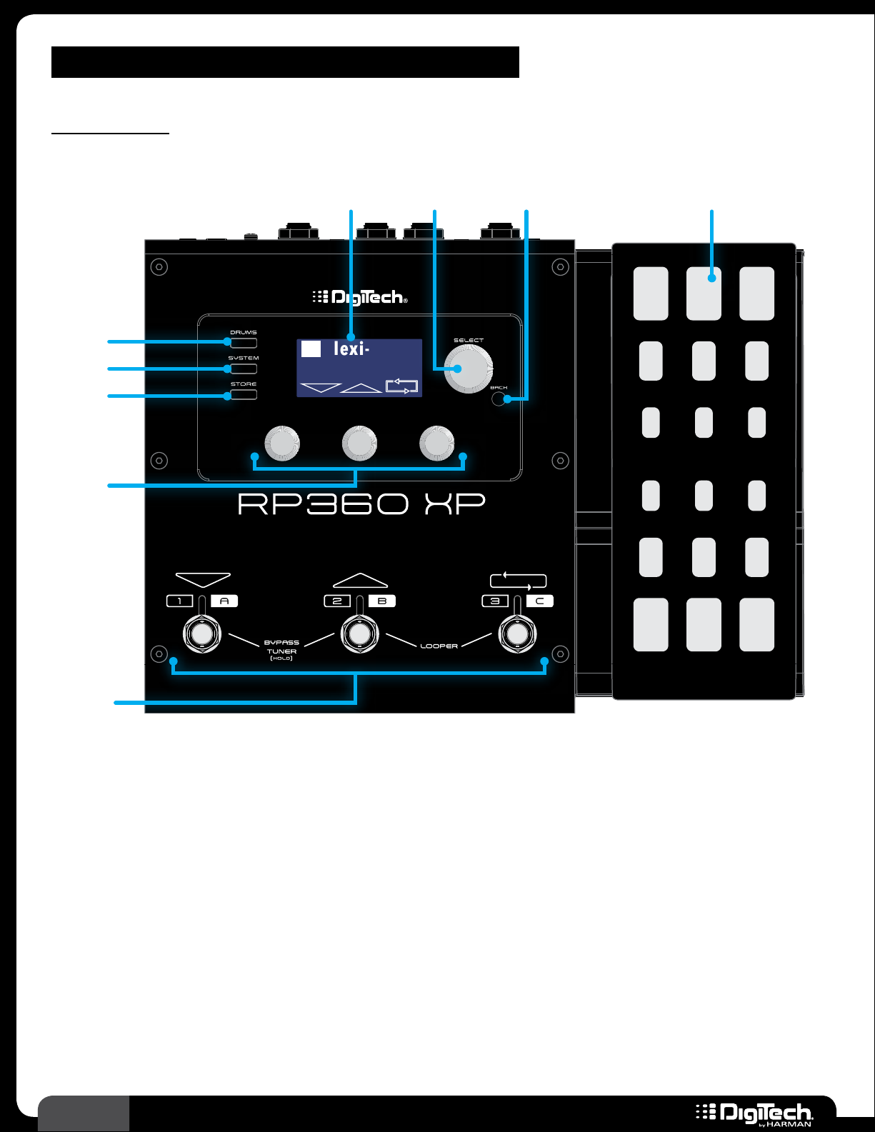
Top Panel
2 3 41
5
6
7
8
Plexi-Drive 1
LOOP ER REA DY
1� LCD DISPLAY
This LCD display provides the visual feedback necessary for operating the RP360/RP360XP
processors�
2� SELECT KNOB
This knob performs different functions when pressed or turned, depending upon which operating
state you are in� In the Performance state, turning this knob navigates presets and pressing this
knob accesses editing of effects and effect settings� When editing presets, turning this knob selects
the effect for editing and pressing this knob navigates the various pages containing parameters for
the selected effect�
3� BACK BUTTON
Press this button to navigate back one level when navigating menus� Press the button multiple times
to get back to the Performance state�
4
RP360 / RP360 XP
Page 9

4� EXPRESSION PEDAL (RP360XP ONLY)
The expression pedal provides real-time control of the Volume, Wah, or an assigned effect
parameter� The expression pedal is equipped with a V-Switch that turns the wah on and off when
you apply extra pressure to the toe� See Expression Pedal Control on page 34 for information
on assigning effect parameters to the expression pedal� See Expression Pedal & LFO Assignable
Parameters on page 110 for a list of assignable parameters�
5� DRUMS BUTTON
Press this button to enter the Drum Machine Edit menu, where you can edit the Drum Machine
parameters (PATTERN, TEMPO, and LEVEL)� Once in the Drum Machine Edit menu, pressing the
DRUMS button will toggle the Drum Machine on and off – or you can press the SELECT knob� See
Drum Machine on page 30 for more information on using the Drum Machine�
NOTE: The Drum Machine cannot be used while the Looper is active� If a loop has been
recorded using the Looper, you must clear the loop before the Drum Machine can be used� To
clear a loop, stop loop playback then press and hold
28 for further information on operating the Looper�
FOOTSWITCH 3� See Looper on page
6� SYSTEM BUTTON
Press this button to access the global System Settings menu, where you can edit global parameters
which determine how the RP360/RP360XP processor functions� See System Setup on page 41
for information on the options and parameters available in this menu�
7� STORE BUTTON
Use this button to store, rename, and copy presets� The STORE button LED will light whenever a
preset’s stored parameters are altered, indicating that the changes must be stored to a user preset
to be retained� See Managing Presets on page 15 for more information on presets�
8� EDIT KNOBS
In this manual, these knobs are referred to as the EDIT 1 knob, EDIT 2 knob, and EDIT 3 knob –
from left to right� These knobs are used to edit on-screen system and effect parameters� From the
Performance state, the EDIT 1 knob will adjust the Preset Level (which affects the output level of
the currently loaded preset only) and the EDIT 3 knob will adjust the Master Level (which affects
the output level of all presets)� See Preset Level & Master Level on page 25 for further
information on these output level controls�
9� FOOTSWITCHES
These footswitches are used for multiple functions and can be configured to operate in Preset
Mode, Stomp Mode, or Bank Mode� See Footswitch Modes on page 41 for more information
on footswitch modes�
RP360 / RP360 XP
5
Page 10
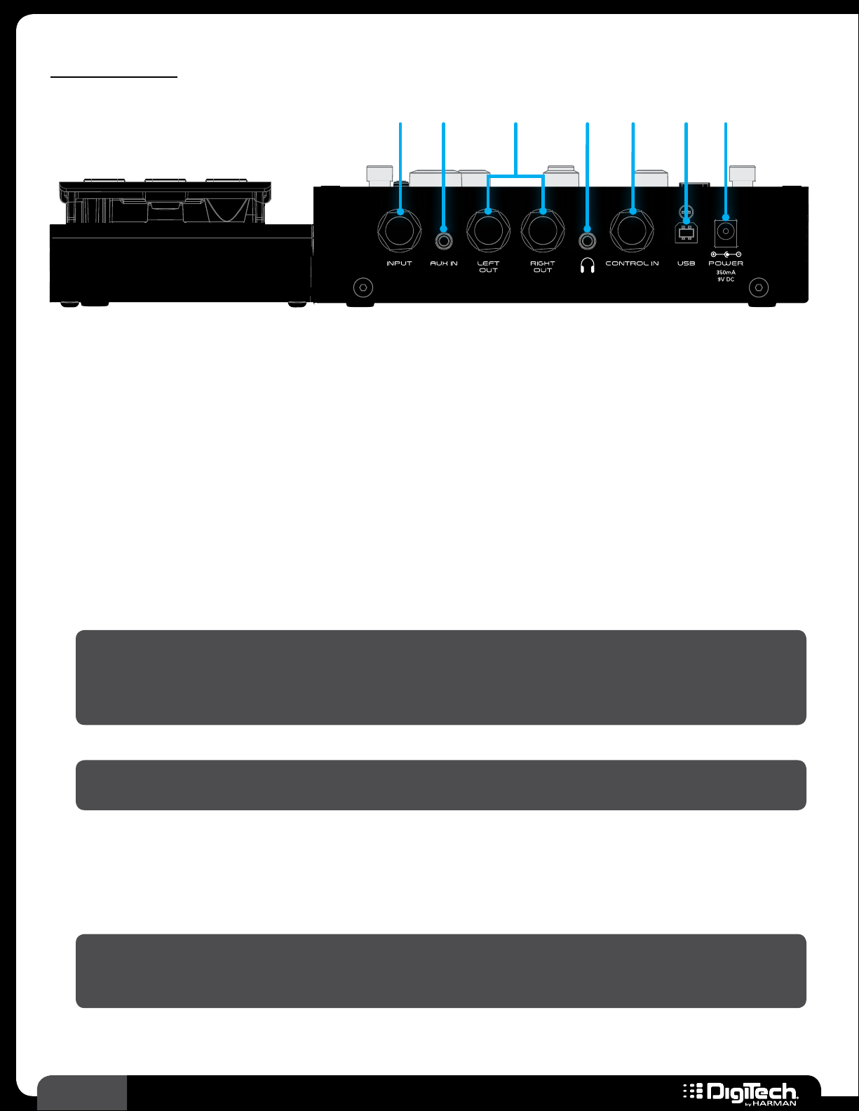
Rear Panel
1 2 3 4 5 6 7
1� INPUT
Connect your guitar to this high impedance 1/4” instrument input�
2� AUX IN
Using a stereo 1/8” cable, connect the headphone output of a portable music player to this 1/8”
TRS connector to play along with all your favorite music� See Aux Input on page 32 for
information on using this feature�
3� LEFT OUT/RIGHT OUT
These 1/4” TRS outputs can be configured for mono or stereo operation� Use them for connecting
to a single guitar amplifier, a stereo pair of guitar amplifiers, or directly into the inputs of a mixer or
recording device�
HINT: When connecting these output connectors directly to a mixer or recording device, you
will want to select the “MIXER” option in the System Settings menu to enable Speaker Cabinet
Compensation (SCC)� See Output To on page 44 for more information on the MIXER
option�
NOTE: Mono/stereo operation is configured in the System Settings menu� See Output Mode
on page 45 for more information on this configuration option�
4� HEADPHONE OUT
Connect your headphones to this 1/8” mini TRS connector� This output is optimized for use with
headphones having an impedance of 60 Ohms or less�
NOTE: When only headphones are connected (nothing connected to the 1/4” outputs), the
outputs are optimized for full range speakers/headphones� See Output To on page 44 for
further information�
6
RP360 / RP360 XP
Page 11

5� CONTROL IN
In the RP360 model, this connector accepts an external expression or volume pedal for real-time
control of effect parameters, or a DigiTech FS3X Footswitch for additional footswitch control� In
the RP360XP model, this connector accepts an FS3X Footswitch for additional footswitch control�
See Expression Pedal Control on page 34 and Using An Optional FS3X Footswitch on
page 37 for further details�
6� USB
This USB connector connects the RP360/RP360XP processor to a computer for preset
management using the Nexus editor/librarian software and/or streaming 4 channels of audio (2
channels to the computer and 2 channels from the computer) for recording to your favorite Digital
Audio Workstation�
7� POWER
Connect only the included PS0913DC power supply to this connector�
RP360 / RP360 XP
7
Page 12
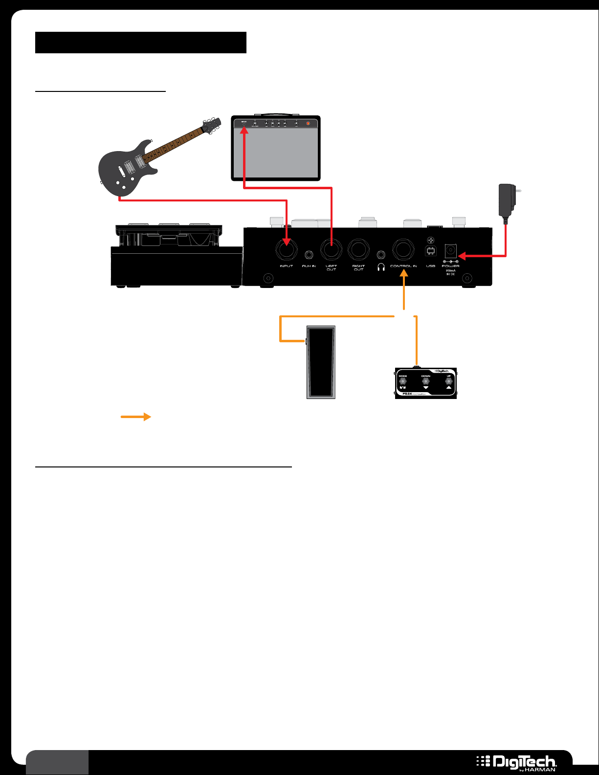
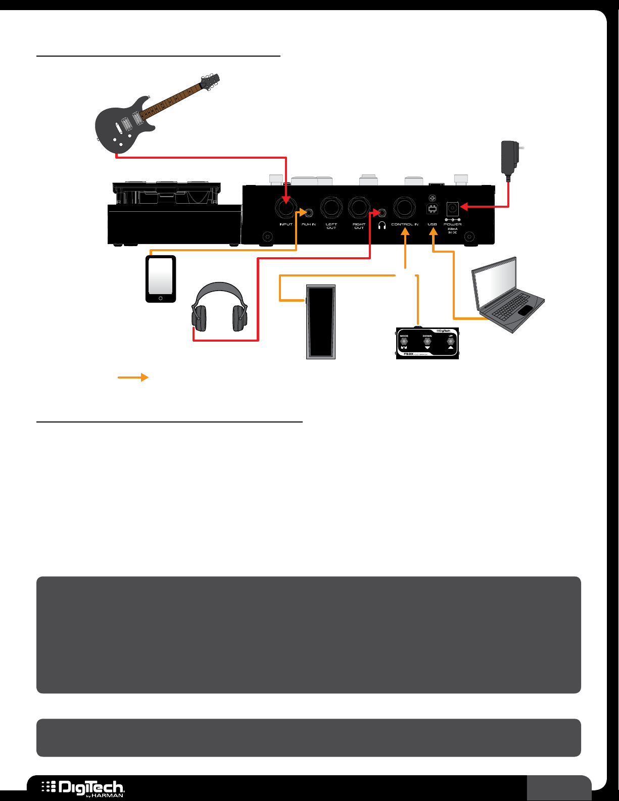
CONNECTION DIAGRAMS
Mono Amplier
Guitar
Amp 1
Harman PS0913DC
Power Supply
Or
Optional
Volume/Expression
Pedal (RP360 Only)
Footswitch
Follow these steps to use the RP with an amplifier:
Turn down the amplifier’s master volume control and power off the amp�
1�
2� Make all the connections to the RP as shown in the diagram�
3� Turn the RP on by connecting the included power supply to the POWER input connector and
connecting the other end to an available AC outlet�
4� Turn on your amplifier� Strum your guitar and gradually increase your amplifier’s master volume
control until the desired level is achieved�
8
RP360 / RP360 XP
Page 13
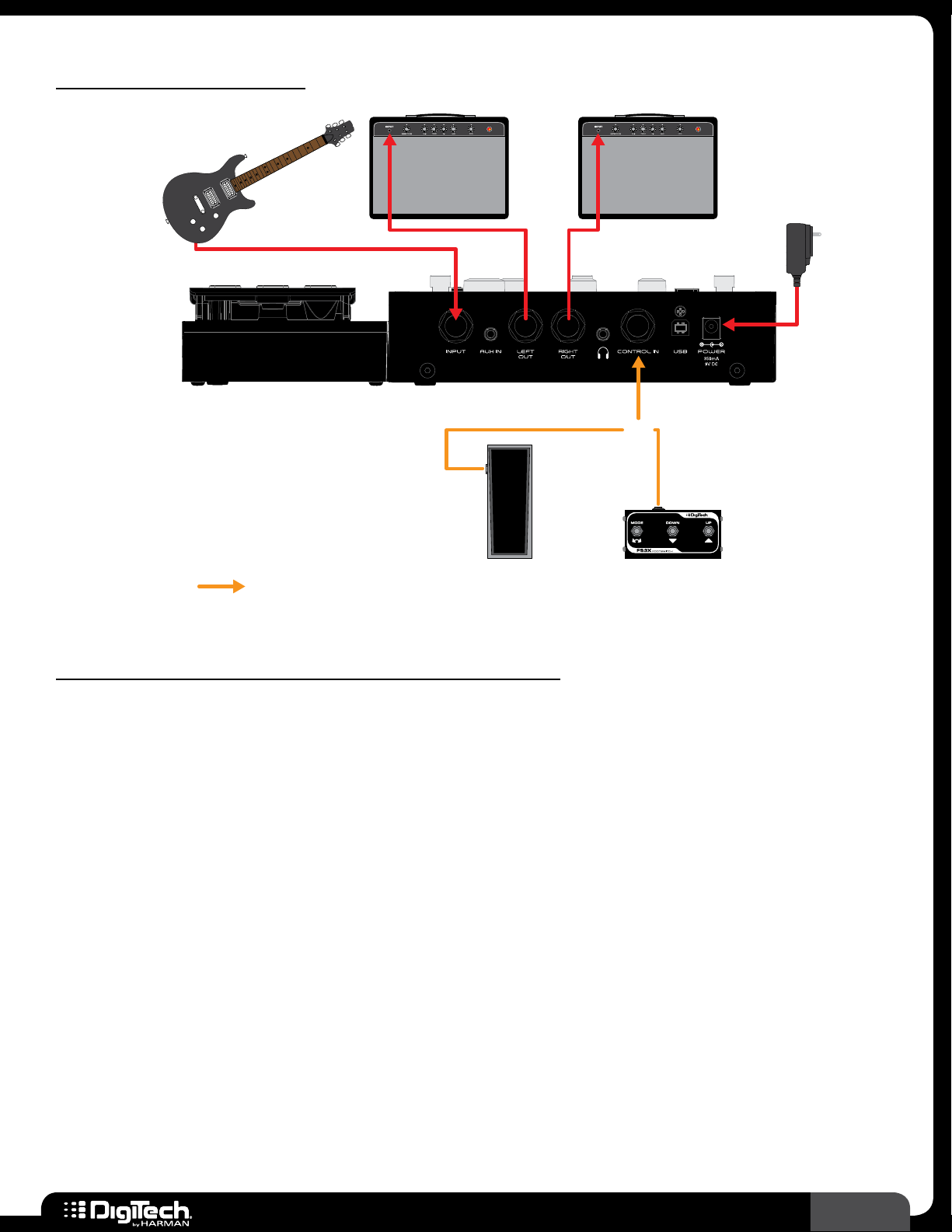
Stereo Ampliers
Guitar
Amp 1 Amp 2
Harman PS0913DC
Power Supply
Or
Optional
Volume/Expression
Pedal (RP360 Only)
Footswitch
Follow these steps to use the RP with a pair of amplifiers:
1� Turn down the amplifiers’ master volume controls and power off the amps�
2� Make all the connections to the RP as shown in the diagram�
3� Turn the RP on by connecting the included power supply to the POWER input
connector and connecting the other end to an available AC outlet�
4� Turn on your amplifiers� Strum your guitar and gradually increase your amplifiers’
master volume controls until the desired level is achieved�
5� For stereo operation you will need to change the OUTPUT MODE parameter to STEREO� See
Output Mode on page 45 for information on configuring the RP for stereo operation�
RP360 / RP360 XP
9
Page 14
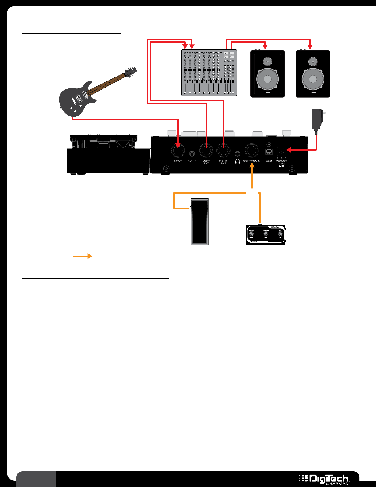
Direct To Mixer/PA
Guitar
Mixer
Powered PA Speakers
Harman PS0913DC
Power Supply
Or
Optional
Volume/Expression
Pedal (RP360 Only)
Footswitch
Follow these steps to use the RP with a mixer:
Lower the master faders on the mixer�
1�
2� Make all connections to the RP as shown in the diagram� Connect the RP to two mixer input
channels� On these two mixer channels, turn down the input gains and faders and set one
channel pan hard left and the other hard right�
3� Turn the RP on by connecting the included power supply to the POWER input connector and
connecting the other end to an available AC outlet�
4� Strum your guitar and adjust the mixer levels until the desired level is achieved� Use proper gain
staging to optimize the signal to noise ratio and prevent clipping of the mixer inputs� Consult
your mixer documentation for information on proper mixer gain staging�
5� Change the OUTPUT TO parameter to MIXER in the System Settings menu� This will optimize
the outputs for full range PA speakers� See Output To on page 44 for more information on
editing this parameter�
6� For stereo operation you will need to change the OUTPUT MODE parameter to STEREO� See
Output Mode on page 45 for information on configuring the RP for stereo operation�
10
RP360 / RP360 XP
Page 15
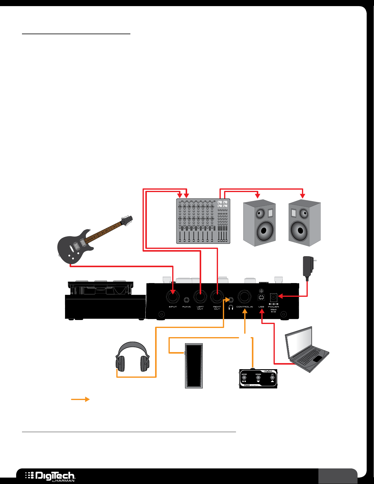
Computer Recording
The RP360 and RP360XP use the standard drivers which come with Mac OS X and Windows
operating systems� Therefore, there are no additional drivers to install� Simply plug in the RP and
connect to your computer�
The RPs will simultaneously stream 2 channels of audio up to the computer and 2 channels of audio
down from the computer at a 44�1kHz sample rate with 16 or 24-bit resolution (bit resolution can
usually be set in your DAW)� Audio recorded via USB is taken from the audio feeding the RP’s LEFT
and RIGHT outputs�
There are two parameters in the RP which are used for controlling your audio levels when recording,
they are: the USB RECORD LVL parameter and the USB PLAY MIX parameter� These parameters allow
you to control the level of the audio being recorded from the RP and the level of the playback audio
from the DAW� See USB Record Level and USB Play Mix on page 47 for more information on
these parameters�
Mixer
Optional
Guitar
Headphones
Volume/Expression
Pedal (RP360 Only)
Powered Monitors
Harman PS0913DC
Power Supply
Or
Computer
Footswitch
Follow these steps to use the RP with a computer recording system:
Lower the master faders on the mixer�
1�
2� Make all connections to the RP as shown in the diagram� Connect the RP to two mixer input
RP360 / RP360 XP
11
Page 16

channels� On these two mixer channels, turn down the input gains and faders and set one
channel pan hard left and the other hard right�
3� Turn the RP on by connecting the included power supply to the POWER input connector and
connecting the other end to an available AC outlet�
4� Strum your guitar and adjust the mixer levels until the desired level is achieved� Use proper gain
staging to optimize the signal to noise ratio and prevent clipping of the mixer inputs� Consult
your mixer documentation for information on proper mixer gain staging�
5� Change the OUTPUT TO parameter to MIXER in the System Settings menu� This will optimize
the outputs for full range studio monitor speakers� See Output To on page 44 for more
information on editing this parameter�
6� For stereo operation you will need to change the OUTPUT MODE parameter to STEREO� See
Output Mode on page 45 for information on configuring the RP for stereo operation�
7� In your DAW, select the RP as the input/output device� See your DAW’s documentation for
further details�
HINT: The DigiTech Nexus editor/librarian software can also be used in this application to edit
effects and manage presets� See Nexus Editor/Librarian Software on page 108 for further
information�
12
RP360 / RP360 XP
Page 17
Practicing With Headphones
Guitar
Harman PS0913DC
Power Supply
Portable
Music Player
Optional
Headphones
Volume/Expression
Pedal (RP360 Only)
Or
Computer
Footswitch
Follow these steps to use the RP with headphones:
Make all the connections to the RP as shown in the diagram�
1�
2� Turn the RP on by connecting the included power supply to the POWER input connector and
connecting the other end to an available AC outlet�
3� Turn the EDIT 3 knob on the RP (the knob just below the SELECT knob) counter-clockwise to
turn the RP’s Master Level control all the way down to 0�
4� Strum your guitar and turn the EDIT 3 knob on the RP clockwise until the desired level is
achieved�
NOTE: When a pair of headphones is connected to the RP’s HEADPHONE connector and no
connections are made to the 1/4” LEFT OUT or RIGHT OUT connectors, the RP will automatically
set the OUTPUT TO parameter to “HEADPHONES IN USE” and the OUTPUT MODE parameter
to “HEADPHONES IN USE”� This ensures the outputs are optimized for headphones and all stereo
effects will be heard in stereo� These settings will return to the way they were configured as soon
as you make a connection to the LEFT OUT or RIGHT OUT connectors� This makes it as simple as
just plugging in your headphones to practice – no reconfiguration necessary!
NOTE: The HEADPHONE output is optimized for use with headphones having an impedance of
60 Ohms or less�
RP360 / RP360 XP
13
Page 18
OPERATING INSTRUCTIONS
Plexi-Drive 1
LOOPER READ Y
Plexi-Drive 1
Plexi-Drive 1
LOOPER READ Y
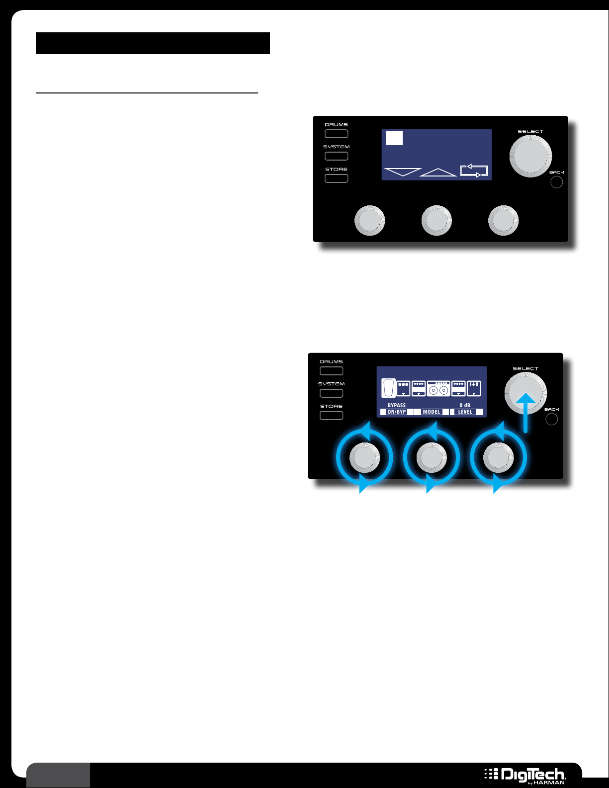
Basic Operation Overview
Performance State
Once the RP is powered up it is ready to use for
performance� This is indicated by the current preset
number and name being displayed in the LCD
display� In this Performance state you can navigate
presets and control the built-in Looper�
There are three Footswitch Modes that can be
used while in the Performance state: Preset Mode,
Stomp Mode, and Bank Mode� For more information on these Footswitch Modes, see Footswitch
Modes on page 41� In the Performance state you can also control the Preset Level and Master
Level parameters by turning the
EDIT 1 and EDIT 3 knobs� See Preset Level & Master Level on
page 25 for more information on these output level parameters�
LOOPER READY
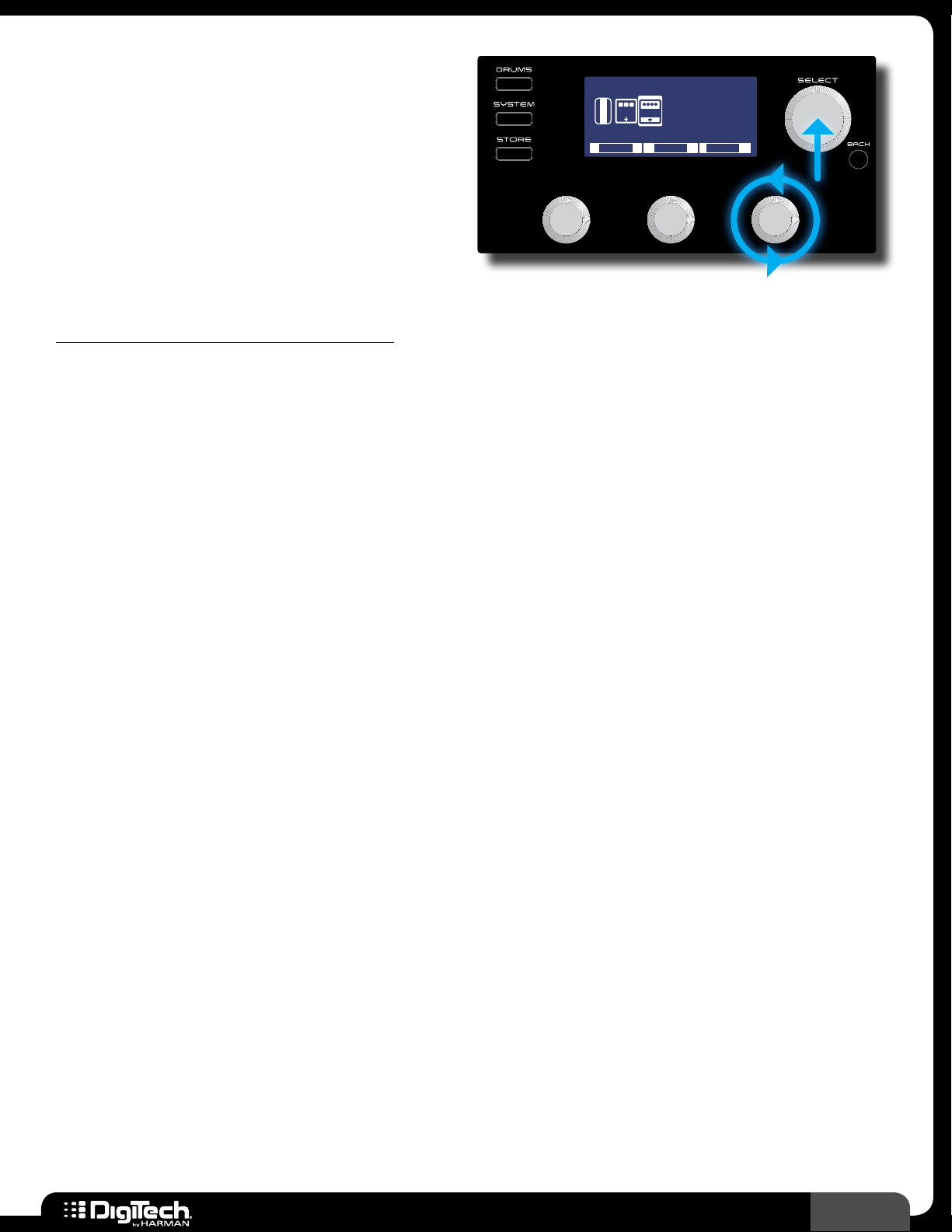
Editing Presets
Press the SELECT knob to access the menus
for editing preset parameters� You can use the
SELECT knob and EDIT 1-3 knobs to navigate
CRY WAH
W
A
CMP DST GAT
H
ON/BYP
MODEL
0 dBBYPASS
LEVEL
1/2
EQ
effects, make changes to effects and effect settings,
and add/delete/move effects in the signal chain�
Once you are finished editing you can exit back
to the Performance state by pressing any of the
three
FOOTSWITCHES or by pressing the BACK
button until the preset number and name are displayed in LCD display� See Working With Effects on
page 19 for more information on editing effects�
System Settings
Pressing the SYSTEM button accesses the global System Settings menu where you can change
footswitch and output modes, USB settings, and perform expression pedal calibration and factory
restore operations� See System Setup on page 41 for more information on system settings�
Drums
Pressing the DRUMS button accesses the built-in Drum Machine� In this menu you have controls for
turning the Drum Machine on and off and changing the drum pattern, tempo and level� See Drum
Machine on page 30 for more information on using the Drum Machine�
14
RP360 / RP360 XP
Page 19
Managing Presets
Plexi-Drive 1
LOOPER READ Y
Plexi-Drive 1
Plexi-Drive 1
LOOPER READY
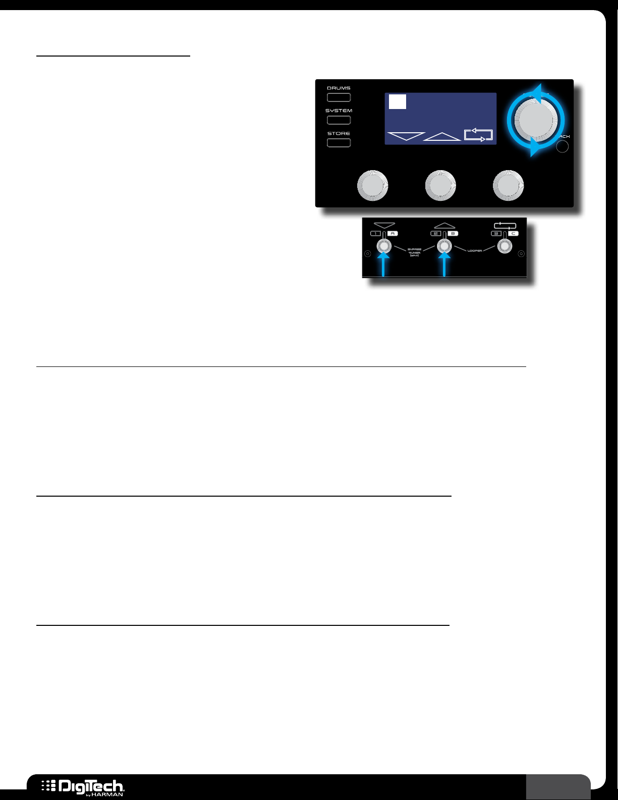
Navigating Presets
There are a total of 198 presets available in the
RP360/RP360XP� These presets are broken up
into two banks, User and Factory, each containing
99 presets� From the factory, the user and factory
presets will contain the same presets� Therefore,
factory preset 45 will be the same as user preset
45 and so on� User presets appear in the LCD
display as 1-99 and factory presets appear as
F1-F99� Preset banks will wrap around when
navigating� In other words, navigating one preset
above user preset 99 will select factory preset 1
(F1) in the factory preset bank� Navigating one
preset below user preset 1 will select factory preset 99 (F99) in the factory preset bank� To navigate
and select presets you must be in the Performance state of operation�
LOOPER READY
To navigate presets using the SELECT knob (Footswitch Mode set to “PRESET” or “STOMP”):
Footswitch Mode must be set to “PRESET” (this is the default Footswitch Mode) or “STOMP”�
1�
For more information on Footswitch Modes, see Footswitch Modes on page 41�
2� Turn the SELECT knob clockwise to navigate up through presets or counter-clockwise to
navigate down through presets�
To navigate presets using the Footswitches (Footswitch Mode set to “PRESET”):
Footswitch Mode must be set to “PRESET” (this is the default Footswitch Mode)� For more
1�
information on Footswitch Modes, see Footswitch Modes on page 41�
2� Press the UP FOOTSWITCH to navigate up through presets and press the DOWN
FOOTSWITCH
to navigate down through presets�
To navigate presets using the Footswitches (Footswitch Mode set to “STOMP”):
Footswitch Mode must be set to “STOMP”� For more information on Footswitch Modes, see
1�
Footswitch Modes on page 41�
2� Press both FOOTSWITCHES 2 and 3 simultaneously� The LCD display will change, now showing
the preset up/down navigation and looper icons, as well as the “LOOPER READY” prompt�
3� Press the UP FOOTSWITCH to navigate up through presets and the DOWN FOOTSWITCH to
navigate down through presets� You’ll notice that the RP is now functioning just as it does when
configured for Preset Mode operation�
RP360 / RP360 XP
15
Page 20

4� When done navigating presets, press both FOOTSWITCHES 2 and 3 simultaneously again� The
LCD display will change and you will now be back to Stomp Mode operation�
To navigate presets (Footswitch Mode set to “BANK”):
Footswitch Mode must be set to “BANK”� For more information on Footswitch Modes, see
1�
Footswitch Modes on page 41�
2� If you want to select a preset from another bank, turn the SELECT knob clockwise to navigate
up through banks or counter-clockwise to navigate down through banks – for easy hands-free
preset bank navigation, an optional FS3X Footswitch should be used� There are 66 total banks
(33 user preset banks (1-33) and 33 factory preset banks (F1-F33))� After a bank is selected, the
3 footswitch LEDs will flash, prompting you to select a preset and activate the bank�
3� The LCD display will show 3 selectable presets in the selected bank� Press the corresponding
FOOTSWITCH
NOTE: If a footswitch is not pressed within approximately 3 seconds, the RP will time out
and revert back to the last active preset bank�
to load the desired preset�
4� You can switch between Preset and Bank Mode operation to navigate presets when in Bank
Mode� To do this, press both
change, now showing the preset up/down navigation and looper icons, as well as the “LOOPER
READY” prompt�
FOOTSWITCHES 2 and 3 simultaneously� The LCD display will
5� Press the UP FOOTSWITCH to navigate up through presets and the DOWN FOOTSWITCH to
navigate down through presets� You’ll notice that the RP is now functioning just as it does when
configured for Preset Mode operation�
6� When done navigating presets, press both FOOTSWITCHES 2 and 3 simultaneously again� The
LCD display will change and you will now be back to Bank Mode operation�
16
RP360 / RP360 XP
Page 21
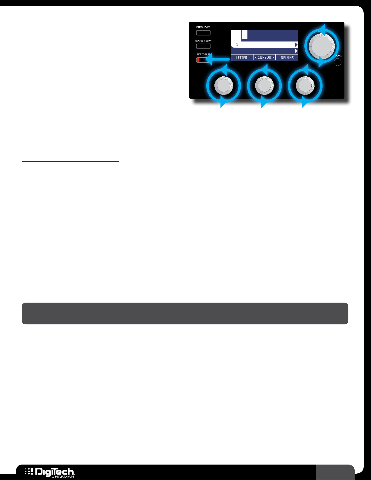
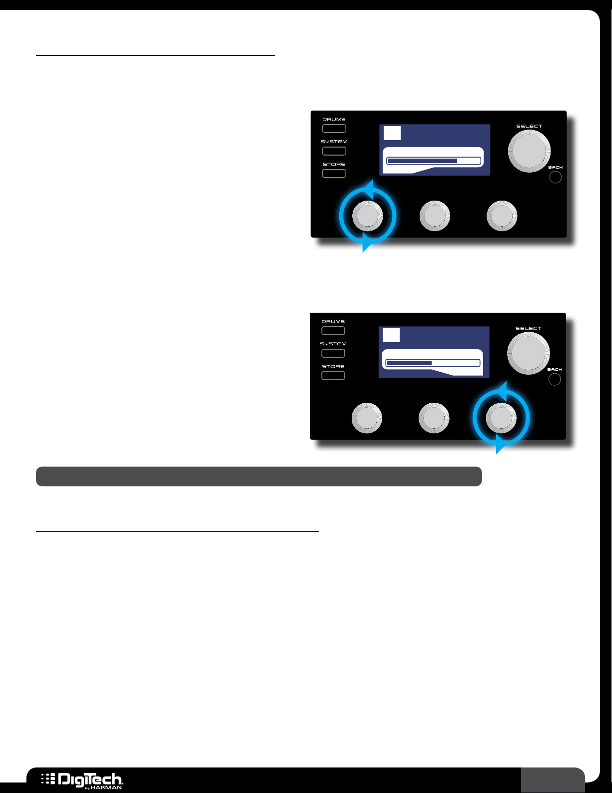
Storing/Copying/Naming Presets
Plexi-Drive 1
LOOPER READ Y
1 lexi-Drive P
The STORE button is used to store edits made
to a preset’s parameters� The STORE button’s
LED will light whenever a preset’s parameters
Plexi-Dri1 :
LETTER DEL/INS
<CURSOR>
have been modified from their stored value� Any
parameter edits must be stored to a preset before
the processor is powered down or the preset is
changed in order for edits to be retained� Preset
edits can only be stored to a user preset
memory location since factory presets cannot be overwritten� The RP360 and RP360XP have 99 user
preset memory locations� Factory presets can be edited and then stored to a user preset location�
When storing a preset you will have the option to change the preset’s name�
STORE TO:
BACK TO CANCEL
To store/copy/rename a preset:
Press the STORE button to initiate the store procedure�
1�
2� If you do not want to change the name of the preset, go to step 3� To modify or change the
name, use the 3
screen character� Turning the
Turning the
character; turning it counter-clockwise will delete characters to the left of the selected
character� The preset name can contain up to 16 characters�
EDIT knobs� Turning the EDIT 1 (LETTER) knob will edit the selected on-
EDIT 2 (CURSOR) knob selects the character you want to edit�
EDIT 3 (DEL/INS) knob clockwise will insert space to the left of the selected
3� If you do not want to change the preset location go to step 4� To select a new preset location,
turn the
name�
SELECT knob until the desired user preset memory location is displayed below the
4� Press the STORE button a second time, or press the SELECT button, to confirm the store
procedure� The LCD display will briefly display “Storing���” then the preset will be stored�
NOTE: Pressing the BACK button at any time during the above store procedure will abort the
procedure�
RP360 / RP360 XP
17
Page 22

To quick store a preset (store a preset to its current memory location with its current name):
Press the STORE button twice� The LCD display will briefly display “Storing���” then the preset
1�
will be stored to its current user preset memory location with its current preset name�
WARNING! If you perform the above quick store procedure on a factory preset, the changes will
be stored to the equivalent user preset memory location� For example, if you load factory preset
5 (F5), make edits, and then press the
Therefore, use caution when performing this procedure on factory presets to ensure you do not
accidentally overwrite one of your existing user presets�
STORE button twice, you will overwrite user preset 5 (5)�
To copy a preset to another preset location with its current name:
Select the preset you would like to copy�
1�
2� Press the STORE button to initiate the store procedure�
3� Turn the SELECT knob until the desired user preset memory location is displayed below the
preset name�
4� Press the STORE button a second time to confirm the store procedure� The LCD display
will briefly display “Storing���” then the preset will be copied to the new user preset memory
location�
18
RP360 / RP360 XP
Page 23
Working With Effects
Plexi-Drive 1
LOOPER READ Y
Effects can be modified, moved around, deleted, and added back into the effects chain� When the RP
is configured for Stomp Mode, they can also be assigned to the three footswitches for effect on/off
control� Up to 10 effects can reside in the effects chain at a time� This section of the manual describes
how to work with the effects available in the RP360 and RP360XP processors�
Editing Effect Parameters
When creating a new sound, you must start with
an existing preset� The easiest way to create a
new custom sound is to first load a preset which
CRY WAH
W
A
CMP DST GAT
H
ON/BYP
MODEL
0 dBBYPASS
LEVEL
1/2
EQ
sounds close to the sound you are after� You can
then edit the effects from there then store the
preset to any of the 99 user preset memory
locations�
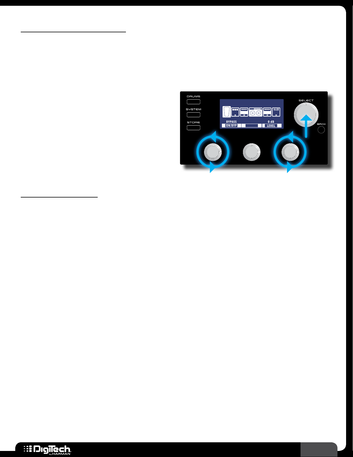
To edit effect parameters:
From the Performance state, press the SELECT knob to enter the Effect Edit menu�
1�
2� Turn the SELECT knob to select the effect you would like to edit�
3� Turn the EDIT knobs to adjust the corresponding on-screen effect parameters� Some effects
will have more than one page of parameters� If an effect has more than one page of parameters
(designated by the 1/X page indicator in the upper right corner of the LCD display), press the
SELECT knob to navigate the various pages�
4� When done, press the BACK button to return to the Performance state�
5� Store the changes to a user preset, see Storing/Copying/Naming Presets on page 17�
RP360 / RP360 XP
19
Page 24
Changing Effects
Plexi-Drive 1
LOOPER READ Y
Most of the effects in the RP360/RP360XP have
multiple effects to choose from� For example, the
Delay effect offers a Ping Pong Delay, Tape Delay,
CRY WAH
W
A
CMP DST GAT
H
ON/BYP
MODEL
0 dBBYPASS
LEVEL
1/2
EQ
Analog Delay, etc��
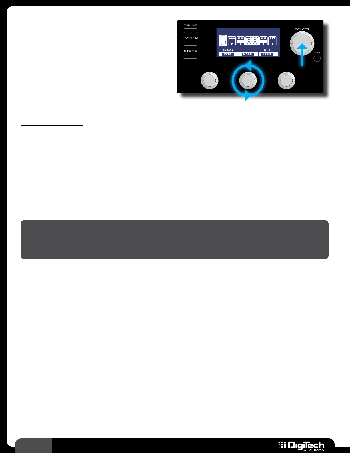
To change an effect:
From the Performance state, press the SELECT knob to enter the Effect Edit menu�
1�
2� Turn the SELECT knob to select the effect you would like to edit�
3� Turn the EDIT 2 knob to change the effect type� The selected effect will be shown at the top of
the LCD display�
4� Repeat steps 2-3 to change any other effects�
5� When done, press the BACK button to return to the Performance state�
6� Store the changes to a user preset, see Storing/Copying/Naming Presets on page 17�
NOTE: Effects can also be changed from the Effect Options Edit menu� This menu is accessed by
pressing and holding the
knob to change the effect model� From this menu, you can also move the effect to a different
1
location in the effects chain or delete an effect from the effects chain�
SELECT knob when in the Effect Edit menu� You can then turn the EDIT
20
RP360 / RP360 XP
Page 25
Reordering Effects
Plexi-Drive 1
LOOPER READ Y
Each effect used in a preset may be moved into a
different position in the effects chain�
SCREAMER
W
A
CMP DST GAT
H
MODEL
MOVE
EQ
DELETE
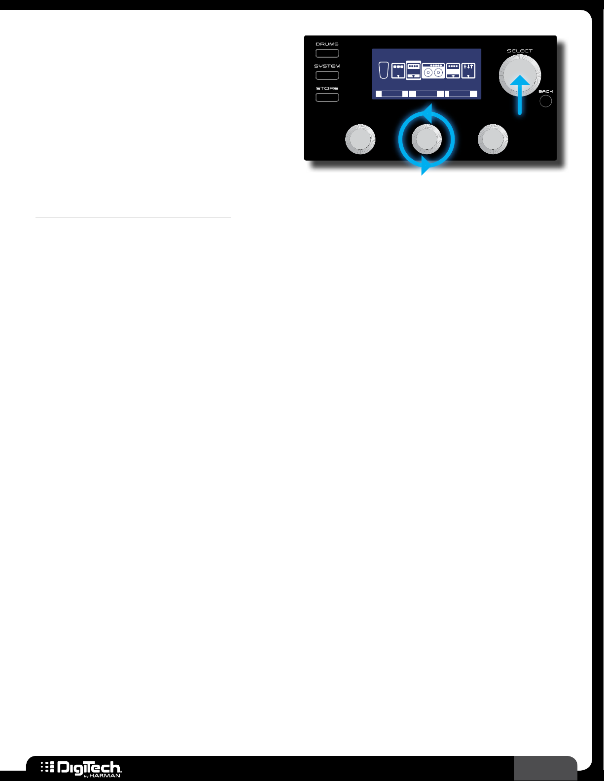
To move an effect in the effects chain:
From the Performance state, press the SELECT knob to enter the Effect Edit menu�
1�
2� Turn the SELECT knob to select the effect you would like to move�
3� Press and hold the SELECT knob to access the Effect Options Edit menu�
4� Turn the EDIT 2 (MOVE) knob to move the selected effect left or right in the effect chain�
5� Press the SELECT knob to confirm the new placement� The display will return to the Effect Edit
menu�
6� Repeat steps 2-5 to move any other effects�
7� When done, press the BACK button to return to the Performance state�
8� Store the changes to a user preset, see Storing/Copying/Naming Presets on page 17�
RP360 / RP360 XP
21
Page 26
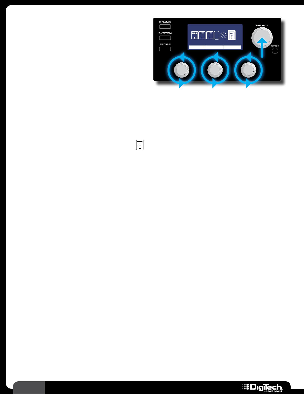
Adding Effects
Plexi-Drive 1
LOOPER READ Y
Up to 10 effects can be used in each preset� If
there is an available effect slot in a preset, the
icon will be displayed near the end of the Effect
Edit menu� This
icon is used to add an effect
Add Effect
V
O
MOD
DLY
L
REVERB, CLICK TO CONFIRM
EFFECT
1/2
E
X
P
to the effects chain� If all 10 slots are already
occupied with effects, the
icon will not be
visible�
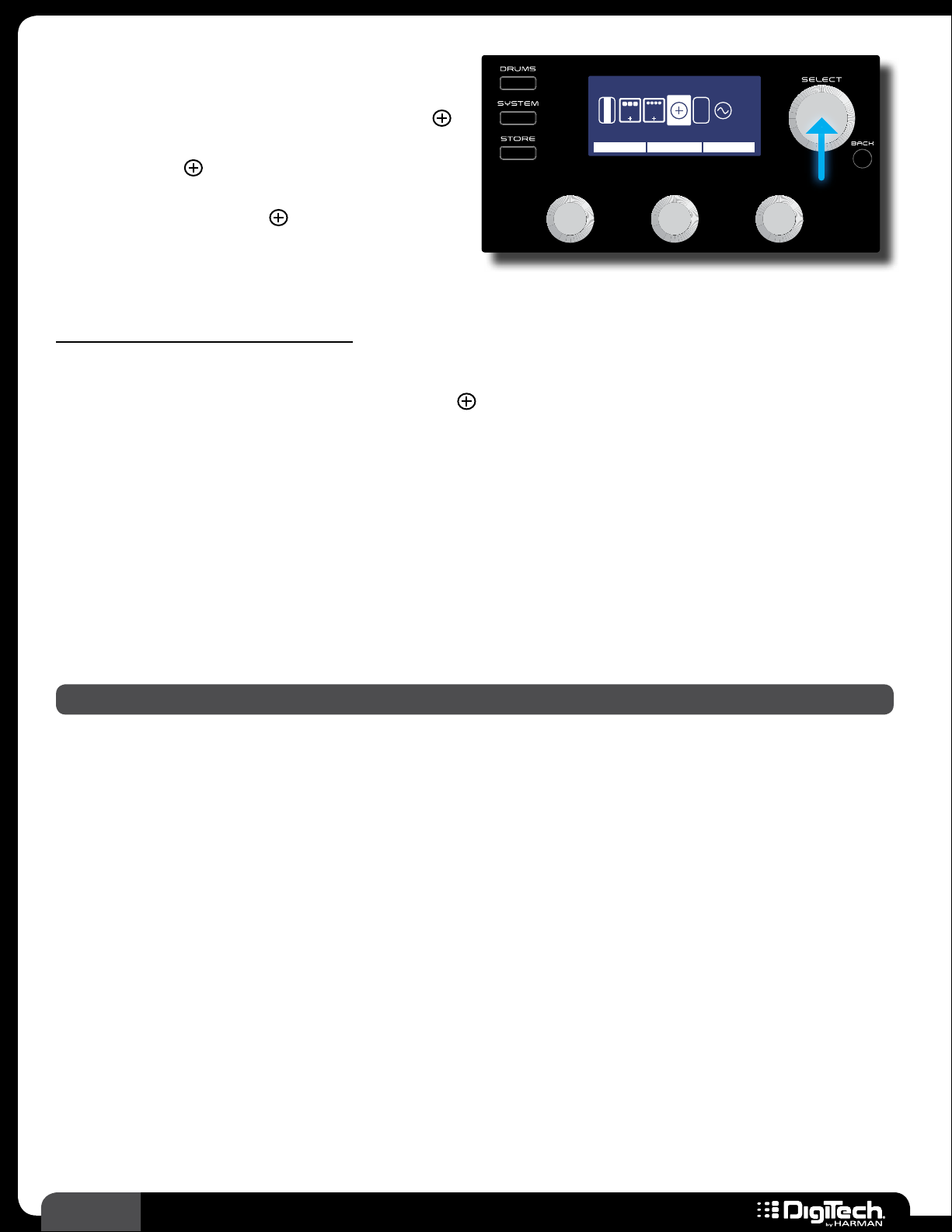
To add an effect to the effects chain:
From the Performance state, press the SELECT knob to enter the Effect Edit menu�
1�
2� Turn the SELECT knob to navigate to the (Add Effect) icon in the chain� “Add Effect” will
appear at the top of the LCD display�
3� Turn the EDIT 1 (EFFECT) knob to select the available effect category (e�g�, Compressor,
Modulation, Reverb, etc�)�
4� Press the SELECT knob to confirm the category selection�
5� You can change the type of the added effect by turning the EDIT 2 (MODEL) knob�
6� Once the desired effect has been selected, press the BACK button to return to the
Performance state�
7� Store the changes to a user preset, see Storing/Copying/Naming Presets on page 17�
NOTE: One of each effect type (Compressor, Distortion, Modulation, etc�) can be used in a preset�
22
RP360 / RP360 XP
Page 27
Deleting Effects
Plexi-Drive 1
LOOPER READ Y
You can delete unused effects from the effects
chain� This is not absolutely necessary since you
can turn any unused effects off, but removing
TAPE DELAY
V
O
MOD
DLY
L
MOVE DELETEMODEL
unused effects can clean up the Effect Edit menu,
making it more streamlined and easier to edit
effects�
To delete an effect from the effects chain:
From the Performance state, press the SELECT knob to enter the Effect Edit menu�
1�
2� Turn the SELECT knob to select the effect you would like to delete�
3� Press and hold the SELECT knob to access the Effect Options Edit menu�
4� Turn the DELETE knob to begin the delete procedure� “CLICK TO CONFIRM DELETE” will
appear in the LCD display� If you change your mind, press the
effect�
BACK button to abort deleting an
5� Press the SELECT knob to confirm deletion� The effect will be deleted from the effects chain
and the display will then return to the Effect Options Edit menu�
6� Press the BACK button twice to return to the Performance state�
7� Store the changes to a user preset, see Storing/Copying/Naming Presets on page 17�
RP360 / RP360 XP
23
Page 28
Assigning Effects To Footswitches
Plexi-Drive 1
LOOPER READ Y
(Stomp Mode Only)
When the RP360/RP360XP is configured for
Stomp Mode operation, effects can be assigned to
Stompbox FSW
E
MOD
DLY REV
ASSIGN A ASSIGN B ASSIGN C
X
P
WAH ON DLY ONDIST ON
1/1
any of the three footswitches� You can then toggle
individual effects in a preset on and off during
performance�
To assign an effect to one of the three footswitches:
The RP must be configured for “Stomp Mode” operation, see Footswitch Modes on page
1�
41 for information on configuring the RP for Stomp Mode operation�
2� From the Performance state, press the SELECT knob to enter the Effect Edit menu�
3� Turn the SELECT knob and select the (Footswitch Assign) icon located at the end of the
effects chain�
4� Turn the corresponding EDIT knobs to select the effects which will be assigned to the A, B, and
C footswitches�
5� When done, press the BACK button to return to the Performance state�
6� Store the changes to a user preset, see Storing/Copying/Naming Presets on page 17�
24
RP360 / RP360 XP
Page 29
Preset Level & Master Level
Plexi-Drive 1
LOOPER READ Y
Plexi-Drive 1
Plexi-Drive 1
LOOPER READ Y
Plexi-Drive
1
The RP360 and RP360XP have two different output level controls: Preset Level and Master Level�
Preset Level
The Preset Level parameter adjusts the output
level for the currently loaded preset only�
Therefore, changes to the Preset Level must
be stored to the preset to be retained� Use the
Preset Level parameter to either match the output
levels of all your presets or set the levels to create
some dynamics in your songs (for example, a lead
guitar part may require a slight boost in level to
push your guitar to the front of the mix and an intro may need a slightly lowered level to make the
first verse sound bigger when it comes in)�
Master Level
The Master Level parameter adjusts the global
output level, which affects the volume of all
presets equally� Use this parameter to increase or
decrease the overall level of all presets�
PRESET LEVEL: 74
MASTER LEVEL: 43
NOTE: All outputs are affected by the Master Level and Preset Level parameters�
To adjust the Preset Level or Master Level parameter:
You must be in the Performance state to adjust these parameters� You should see the preset
1�
number and name in the LCD display� If you do not, press the
2� Turn the EDIT 1 knob to adjust the Preset Level� Turn the EDIT 3 knob to adjust the Master
Level� While adjusting each parameter, the LCD display will temporarily display the level values
as they are adjusted� After approximately 2 seconds of inactivity, the level parameter window
will automatically disappear�
3� If you made changes to the Preset Level, the STORE button will light, indicating you must
store the changes to a user preset� See Storing/Copying/Naming Presets on page 17 for
information on storing presets�
BACK button until you do�
RP360 / RP360 XP
25
Page 30
Preset (Effects) Bypass
Plexi-Drive 1
LOOPER READY
BYPASS
The Preset Bypass feature bypasses all effects in the currently
loaded preset and feeds only the dry (unprocessed) signal to
the outputs� While a preset is bypassed, no other functions are
available� The bypassed guitar signal will be passed up USB while
bypass is active, but no audio will be heard from the computer
via USB� Bypass is accessed in different ways depending on the
selected Footswitch Mode� See Footswitch Modes on page 41
for more information on Footswitch Modes�
To bypass a preset’s effects (Footswitch Mode set to “PRESET” or “STOMP”):
Press FOOTSWITCHES 1 and 2 simultaneously to enable Preset Bypass� “BYPASS” will appear
1�
in the LCD display�
2� When done, press any footswitch to exit Preset Bypass�
To bypass a preset’s effects (Footswitch Mode set to “BANK”):
Press the currently active preset’s FOOTSWITCH (indicated by the lit LED above the
1�
footswitch)� “BYPASS” will appear in the LCD display�
2� When done, press any footswitch to exit Preset Bypass�
26
RP360 / RP360 XP
Page 31

Tuner
Plexi-Drive 1
LOOPER READ Y
E
A= 440 HZ
TUNER REF
Plexi-Drive 1
LOOPER READY
The built-in Tuner lets you quickly tune your guitar
and is accessed in different ways depending on
the selected Footswitch Mode� See Footswitch
Modes on page 41 for more information on
Footswitch Modes�
Parameters
PARAMETER NAME DESCRIPTION
Selects the pitch which the tuner uses for referencing the note A above middle C� Reference
TUNER REF
settings range from A=G♭, A=G, A=A♭, and A=427Hz-453Hz. The default setting is
A=440Hz – this is the standard tuning reference�
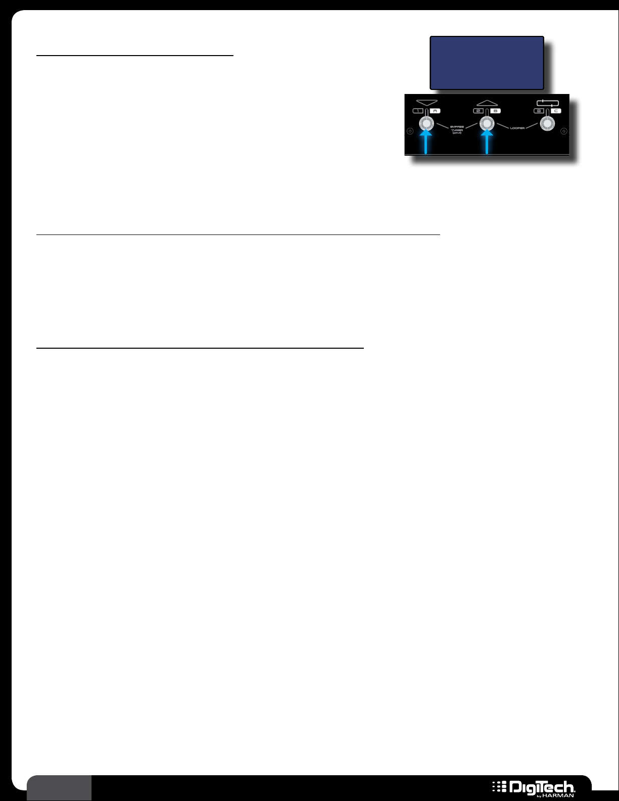
To use the Tuner (Footswitch Mode set to “PRESET” or “STOMP”):
Press and hold FOOTSWITCHES 1 and 2 simultaneously for approximately 2 seconds to enable
1�
the Tuner�
2� To change the tuning reference, turn the EDIT 1 (TUNE REF) knob�
3� Play an open string on your guitar� The detected note will be shown in the middle of the LCD
display and indicators will point you in the direction the string needs to be tuned� Adjust the
string’s pitch until the proper note is displayed and the upward-facing arrow is pointed as close
as possible to the center line (as shown in the screenshot at the top of this page)� Tune the
remaining strings in the same manner�
4� To exit the Tuner, press any FOOTSWITCH�
To use the Tuner (Footswitch Mode set to “BANK” ):
Press and hold the currently active preset’s footswitch (indicated by the lit LED above the
1�
footswitch) for approximately 2 seconds� The Tuner will appear�
2� To change the tuning reference, turn the EDIT 1 (TUNE REF) knob�
3� Play an open string on your guitar� The detected note will be shown in the middle of the LCD
display and indicators will point you in the direction the string needs to be tuned� Adjust the
string’s pitch until the proper note is displayed and the upward-facing arrow is pointed as close
as possible to the center line (as shown in the screenshot at the top of this page)� Tune the
remaining strings in the same manner�
4� To exit the Tuner, press any FOOTSWITCH�
RP360 / RP360 XP
27
Page 32

Looper
Plexi-Drive 1
LOOPER READY
Plexi-Drive 1
RECORDING
The RP360 and RP360XP feature a 40-second phrase Looper�
The Looper can be used for looping your guitar parts� Use the
Looper to write or practice lead guitar parts over a looped phrase,
or use it for creating on-the-fly loop layers to enhance your live
performance� The following instructions describe how to use the
Looper�
NOTE: The Looper and Drum Machine cannot be used at the same time� If the Drum Machine is
turned on, you must first turn it off before you can use the Looper� To turn the Drum Machine off,
press the
To use the Looper:
1�
2� If the RP is set to Preset Mode (this is the default Footswitch Mode) you can skip this step�
DRUMS button twice�
The Phrase Sampler option in the System Settings menu must be set to LOOPER (this is the
default setting from the factory)� See Phrase Sampler on page 51 for information on
changing this setting�
If the RP is set to Bank Mode or Stomp Mode, you will need to press
FOOTSWITCHES 2
and 3 simultaneously to access the Looper� See Footswitch Modes on page 41 for more
information on Footswitch Modes�
3� Press FOOTSWITCH 3 to arm the Looper for recording� The LCD display will read
“RECORDING ARMED” and the RP is now ready to begin recording�
4� Begin playing a phrase on the guitar� The Looper will begin recording and the LCD display will
read “RECORDING”�
5� When done recording, press FOOTSWITCH 3 again to end loop recording� The loop will
continue to play and you can now play along with it or add overdubs�
HINT: You can navigate presets at this point using the UP/DOWN footswitches or SELECT
knob� This allows you to select different preset sounds that you can play along with the
recorded loop or use for recording overdubs� Changing presets will not change the sound of
the recorded loop�
6� To add an overdub, press FOOTSWITCH 3 once� The LCD display will read “OVERDUBBING”�
Play the overdubbed guitar part�
7� Press FOOTSWITCH 3 once to end overdub recording� The loop will continue to play along
with the newly recorded overdub� Repeat steps 6 and 7 to record additional overdubs�
8� When done, press FOOTSWITCH 3 two times quickly to stop loop playback�
9� With playback stopped, press and hold FOOTSWITCH 3 for 2 seconds to clear the recorded
loop and prepare the RP to record a new loop� The LCD display will again read “LOOPER
READY” and you can repeat the above steps�
28
RP360 / RP360 XP
Page 33

Sound Check
Plexi-Drive 1
LOOPER READ Y
The Sound Check feature places the built-in
Looper at the beginning of the effects chain� This
SYSTEM SETTINGS 3/4
CONTROL
IN
FS3X
LOOPER
EXP/VOL
EXP/TRS SOUND
PHRASE
SAMPLER
CHECK
LOOPER
allows you to record a dry guitar loop that will be
played through the effects� This eliminates the need
to continually strum your guitar when auditioning
effect edits and provides a much more efficient,
convenient, and fun way to edit your presets�
To use Sound Check:
Press the SYSTEM button to enter the System Settings menu�
1�
2� Press the SYSTEM button repeatedly until page 3/4 is selected in the upper right-hand corner
of the LCD display�
3� Turn the EDIT 3 knob to set the PHRASE SAMPLER to the SOUND CHECK option�
4� Press the BACK button to return to the Performance state�
5� If you are currently in Bank Mode or Stomp Mode, you will need to press FOOTSWITCHES 2
and 3 simultaneously to access the Looper� If you are currently set to Preset Mode (this is the
default mode) you can skip this step�
6� Press FOOTSWITCH 3 to arm the Looper for recording then start playing�
7� Press FOOTSWITCH 3 again to set the loop end point�
8� The loop will now continue playing and you can navigate presets and edit effects while listening
to the changes� See Managing Presets on page 15 and Working With Effects on page
19 for information on performing these functions�
9� When done using the Sound Check feature, press FOOTSWITCH 3 twice to stop loop
playback�
10� If you wish to disable the Sound Check feature and re-enable the Looper, perform steps 1-3,
this time setting the PHRASE SAMPLER back to LOOPER�
RP360 / RP360 XP
29
Page 34

Drum Machine
Plexi-Drive 1
LOOPER READ Y
Drums ON
The built-in Drum Machine offers 60 drum
and metronome patterns to choose from and
PATTERN TEMPO LEVEL
100 40BEATS1
is a great tool for improving your timing skills
and practicing your riffs� The Drum Machine
parameters can be accessed by pressing the
DRUMS button�
NOTE: The Looper and Drum Machine cannot be used at the same time� If you have recorded
a loop using the Looper, you must first clear the loop before turning on the Drum Machine� To
clear the loop, enter the Performance state and press
loop playback� With playback stopped, press and hold
FOOTSWITCH 3 two times quickly to stop
FOOTSWITCH 3 for 2 seconds to clear the
recorded loop�
Parameters
PARAMETER NAME DESCRIPTION
PATTERN Selects from the various drum and metronome
patterns
TEMPO Adjusts the Drum Machine tempo (40 BPM-240
BPM)
LEVEL Adjusts the Drum Machine level
Drum Pattern List
DISPLAY NAME DESCRIPTION DISPLAY NAME DESCRIPTION
BEATS1-5 8th Beat JAZZ1-4 Jazz
BEATS6-8 16th Beat HIPHP1-4 Hip Hop
ROCK1-8 Rock WORLD1-4 World
HROCK1-8 Hard Rock MET4/4
METAL1-8 Metal MET3/4
BLUES1-8 Blues MET5/8
GROOV1-4 Groove MET7/8
CNTRY1-4 Country MTRNOM Straight metronome with no accent
Metronome with accent and 4/4 time
signature
Metronome with accent and 3/4 time
signature
Metronome with accent and 5/8 time
signature
Metronome with accent and 7/8 time
signature
To use the Drum Machine:
Press the DRUMS button� You will now be in the Drum Edit menu�
1�
2� Press the DRUMS button again, or the SELECT button, to activate the Drum Machine� The
DRUMS button will light and the upper right corner of the LCD display will indicate the Drum
Machine is “ON”�
30
RP360 / RP360 XP
Page 35

3� Turn the EDIT 1 (PATTERN) knob to change the drum pattern�
4� Turn the EDIT 2 (TEMPO) knob to change the tempo�
5� Turn the EDIT 3 (LEVEL) knob to adjust the Drum Machine’s level�
6� When done, press the DRUMS button to deactivate the Drum Machine�
7� Press the BACK button to return to the Performance state�
NOTE: The Drum Machine’s parameters are global and are not stored to presets�
RP360 / RP360 XP
31
Page 36

Aux Input
1/8” Stereo Cable
The AUX IN connector is used to connect a portable music player or other line-level music playback
device to the RP and jam along with your favorite music� The signal from your playback device will
not pass through any effects and will be output through the RP’s LEFT OUT, RIGHT OUT, and
HEADPHONE connectors�
To use the AUX IN connector:
Connect the headphone output of your music playback device to the AUX IN connector on
1�
the rear panel of the RP using an 1/8” stereo cable as shown below�
2� Press play on your music playback device�
3� Adjust your music playback device’s volume control and the RP’s Master Level control to
achieve the desired mix balance� See Preset Level & Master Level on page 25 for
information on adjusting the RP’s MASTER LEVEL control�
Left
Channel (+)
Ground
Right
Channel (+)
1/8” Stereo Cable
Left +
Ground
Right +
Left
Channel (+)
Ground
Right
Channel (+)
32
RP360 / RP360 XP
Page 37

Tap Tempo
Tap Tempo lets you adjust the delay time during performance by tapping a footswitch in time with the
music�
NOTE: You must configure the RP for Stomp Mode operation, have a Delay effect in the loaded
preset, and have the Delay effect assigned to a footswitch to use the Tap Tempo feature�
To use Tap Tempo:
Configure the RP for STOMP MODE operation in the System Settings menu� See Footswitch
1�
Modes on page 41 for information on configuring the RP for Stomp Mode operation�
2� Load a preset which has an active Delay effect or add a Delay effect to your preset of choice�
Most presets will have a Delay effect already inserted in the effects chain� For information on
adding and editing effects, see Working With Effects on page 19�
3� Assign the Delay effect to one of the 3 footswitches� The footswitch assigned to the Delay
will be the one used for Tap Tempo� Most presets in the RP will already have the Delay effect
assigned to one of the three footswitches� See Assigning Effects To Footswitches (Stomp
Mode Only) on page 24 for information on how to assign the Delay effect to a footswitch�
4� From the Performance state, press and hold the FOOTSWITCH assigned to the Delay for
approximately 2 seconds� The LED above the footswitch will begin flashing at the rate of the
currently set delay time�
5� Tap the Delay assigned FOOTSWITCH at the desired rate to adjust the delay time� The LED
above the footswitch will update, flashing at the rate of the new delay time�
6� When done, press and hold the FOOTSWITCH assigned to the Delay for approximately 2
seconds to exit Tap Tempo� The LED above the footswitch will stop flashing�
RP360 / RP360 XP
33
Page 38

Expression Pedal Control
Plexi-Drive 1
LOOPER READ Y
The RP360XP comes with a built-in expression
pedal which can be assigned to control the
™
RP360XP’s Volume, Wah, Whammy
, Ya Ya™, or
Expression Pedal
V
O
MOD
DLY
L
WAH MIN MAX
0PEDAL 99
1/1
E
X
P
nearly any of the RP360XP’s effect parameters, in
real time with your foot� The RP360 can also be
controlled in a similar manner using an external
expression or volume pedal connected to the
CONTROL IN connector on the rear panel�
When a parameter is assigned for expression pedal control, a MIN (toe up) and MAX (toe down)
value can also be specified� This allows you to set upper and lower limits for the expression pedal’s toe
up (MIN) and toe down (MAX) positions� For example, let’s say you are controlling volume and you
don’t want the expression pedal’s toe up position to completely lower the volume� You could adjust
the MIN parameter to a setting above 0, let’s say 12� Now when the expression pedal is set to the toe
up (minimum) position, the signal will not be fully attenuated since the expression pedal is not allowed
to adjust the volume any lower than 12�
Since all the expression pedal parameters can be stored to user presets, each user preset can have a
different parameter assigned for expression pedal control along with different MIN and MAX range
settings� See Expression Pedal & LFO Assignable Parameters on page 110 for a list of assignable
parameters�
The built-in expression pedal in the RP360XP has a V-Switch which toggles the Wah effect on and off�
To use the V-Switch, place the expression pedal in its toe down position and then apply extra pressure
to the toe of the expression pedal – the sensitivity for this V-Switch can be adjusted when calibrating
the expression pedal� A Wah effect must reside in the effects chain in order for the V-Switch to be
active� By default, all presets in the RP360XP will contain a Wah effect in the effects chain�
You can also choose to assign an LFO (Low Frequency Oscillator) to an effect’s parameter� This is
similar to assigning an effect parameter to an expression pedal, with the exception that it creates
an effect which modulates at a predetermined rate� See Assigning The LFO on page 36 for
information on using an LFO to modulate the signal�
To link a parameter for expression pedal control and set the MIN/MAX range values:
If using an RP360, you must first enable the CONTROL IN port for expression pedal control�
1�
See Control In on page 49 for information on configuring the RP360 for external
expression pedal control�
2� The effect you wish to control must be inserted in the effects chain to assign it for expression
pedal control� If it is not, you will need to add it� See Adding Effects on page 22 for
information on adding effects�
3� It helps to enable the effect you wish to assign to the expression pedal first, so you can audition
the expression pedal control as you are setting it up� See Editing Effect Parameters on page
34
RP360 / RP360 XP
Page 39

19 for information on turning effects on and off� You can also enable the Sound Check
E
X
P
feature and record a loop which can be used to make auditioning the parameter changes even
easier� See Sound Check on page 29 for more information on using Sound Check�
4� From the Performance state, press the SELECT knob to enter the Effect Edit menu�
5� Turn the SELECT knob until you select the
parameter will be displayed above the
EDIT 1 knob�
(Expression Pedal) icon� The currently assigned
6� Turn the EDIT 1 knob to select the parameter you wish to control� You can rock the expression
pedal back and forth to audition the control�
7� Turn the EDIT 2 (MIN) knob to adjust the minimum selectable value for the expression pedal’s
toe up position� You can rock the expression pedal back and forth to audition the control�
8� Turn the EDIT 3 (MAX) knob to adjust the maximum selectable value for the expression pedal’s
toe down position� You can rock the expression pedal back and forth to audition the control�
9� When done, press the BACK button to return to the Performance state�
10� Store the changes to a user preset� See Storing/Copying/Naming Presets on page 17 for
further information on storing presets�
NOTE: The RP360’s external and RP360XP’s built-in expression pedal must be properly calibrated
to work correctly� If you experience any issues with the expression pedal and suspect it may need
recalibration, see Calibrate Pedal on page 52 for information on recalibrating the expression
pedal�
RP360 / RP360 XP
35
Page 40

Assigning The LFO
Plexi-Drive 1
LOOPER READ Y
Similar to linking an effect parameter to an
expression pedal for control, you can also
LFO
V
O
MOD
DLY
L
AMP MIN MAX
0GAIN 99
1/2
E
X
P
link an effect parameter to an LFO (Low
Frequency Oscillator) for control� This can be
used for creating effects which modulate at a
predetermined rate� You can select the parameter
to control, the waveform type, adjust the speed,
and adjust the control range limits using the MIN
and MAX parameters� See LFO on page 84 for further information on LFO parameters� See
Expression Pedal & LFO Assignable Parameters on page 110 for a list of assignable parameters�
To link a parameter for LFO control and adjust the LFO parameters:
From the Performance state, press the SELECT knob to enter the Effect Edit menu�
1�
2� Turn the SELECT knob until the (LFO) icon is selected� The currently assigned parameter
will be displayed above the
EDIT 1 knob�
3� Turn the EDIT 1 knob to select the parameter you wish to control�
4� Turn the EDIT 2 (MIN) knob to adjust the minimum selectable value for the LFO range�
5� Turn the EDIT 3 (MAX) knob to adjust the maximum selectable value for the LFO range�
6� Press the SELECT knob to view the remaining LFO parameters� Use the corresponding EDIT
knobs to adjust the SPEED and WAVEFRM parameters – these parameters determine the rate
and behavior of the modulation�
7� When done, press the BACK button to return to the Performance state�
8� Store the changes to a user preset, see Storing/Copying/Naming Presets on page 17�
36
RP360 / RP360 XP
Page 41

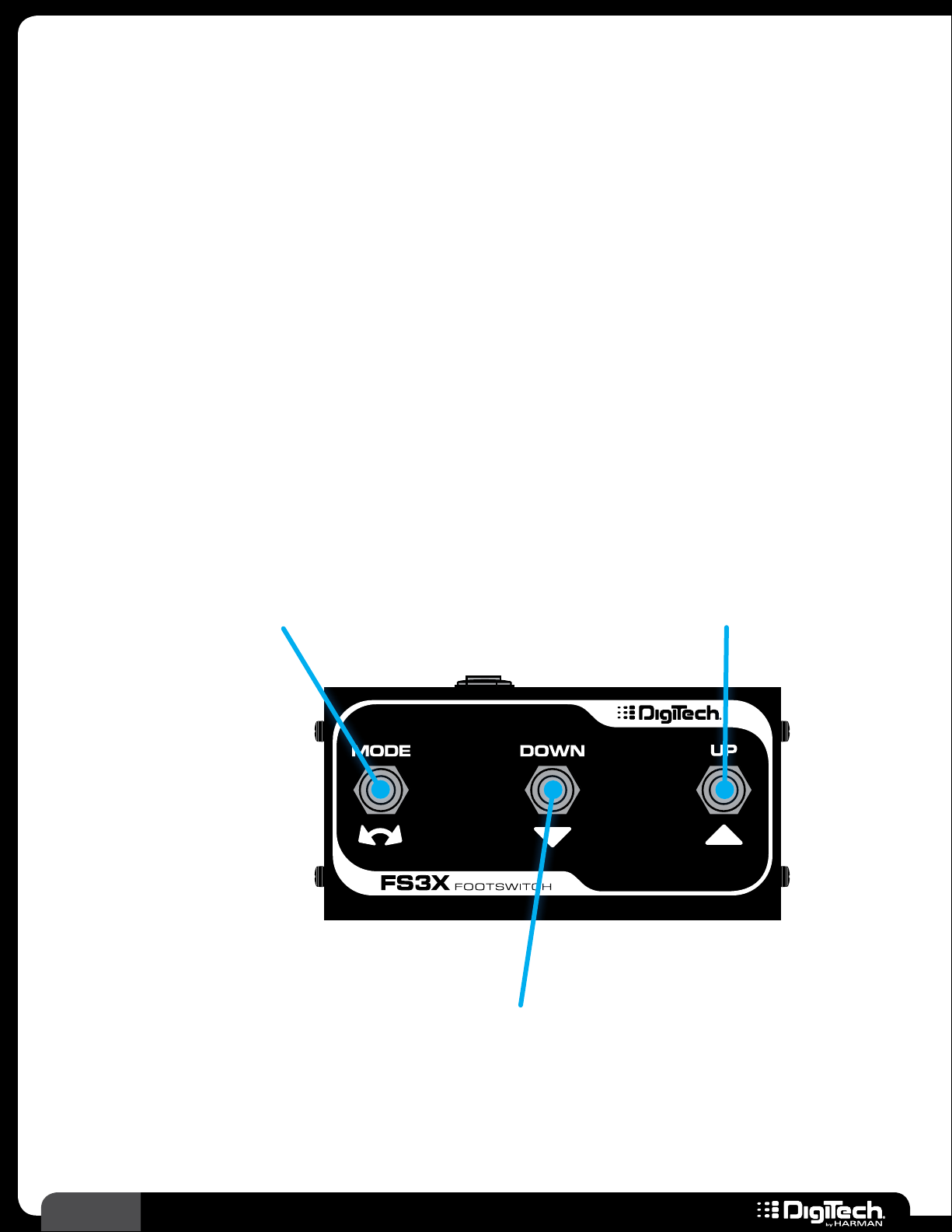
Using An Optional FS3X Footswitch
Plexi-Drive
1
Plexi-Drive
1
Plexi-Drive
1
An optional DigiTech FS3X Footswitch can be connected to the RP’s CONTROL IN connector to add
three additional footswitches for RP control� There are two parameters in the System Settings menu
that will determine how these FS3X footswitches will function, they are: the CONTROL IN parameter
and the FOOTSWITCH MODE parameter� These parameters are accessed by pressing the
button� See Control In on page 49 for further information on changing the CONTROL IN option�
See Footswitch Modes on page 41 for further information on changing the RP’s FOOTSWITCH
MODE�
FS3X Footswitch Functions
The below matrix shows the functions each of the FS3X footswitches will perform depending upon
how you configure the CONTROL IN and FOOTSWITCH MODE parameters�
SYSTEM
DISPLAY
FS3X
FOOTSWITCH
CONTROL IN
SET TO “FS3X”
CONTROL IN
SET TO “LOOPER”
FOOTSWITCH MODE
SET TO “PRESET”
LOOPER READY
Preset
Bypass
*Multi
Loop
Tuner -
Stop
Loop
Clear
Loop
FOOTSWITCH MODE
SET TO “STOMP”
MOD FX DELAY
*Multi
Loop
*Multi
Loop
Preset
Down
Stop
Loop
REVERB
Preset Up*Multi
Clear
Loop
*Multi
FOOTSWITCH MODE
SET TO “BANK”
BANK: 1
1 2 3
Bank
Loop
Loop
Down
Stop
Loop
Bank
Up
Clear
Loop
*Multi Loop means a single footswitch controls multiple Looper functions. See the diagrams on the following
pages to see each of these Looper functions.
RP360 / RP360 XP
37
Page 42

FS3X Operation
(CONTROL IN Set To “FS3X”, FOOTSWITCH MODE Set To “STOMP”)
When the “FS3X” CONTROL IN option is selected and the “STOMP” FOOTSWITCH
MODE option is selected, the FS3X Footswitch can be used for full-time control of preset
navigation and the Looper� The below diagram shows the available functions�
Arm Loop Recording
Press once to arm the Looper for recording�
Record Loop
Once armed, start playing or press again to
start loop recording� When done recording,
press once more to set the loop end point�
Record Overdub Loop
When a loop is recorded and playing back,
press once to start overdub recording� Press
again to stop overdub recording�
Preset Down
Press to navigate down
through presets�
Preset Up
Press to navigate up
through presets�
Stop Loop Playback
When a loop is recorded and playing, press
twice quickly to stop loop playback�
Play Loop
When a loop is recorded and playback is
stopped, press once to start loop playback�
Clear Loop
When a loop is recorded and playback is
stopped, press and hold to clear loop�
38
RP360 / RP360 XP
Page 43

FS3X Operation
(CONTROL IN Set To “FS3X”, FOOTSWITCH MODE Set To “BANK”)
When the “FS3X” CONTROL IN option is selected and the “BANK” FOOTSWITCH MODE option
is selected, the FS3X Footswitch can be used for full-time control of preset bank navigation and the
Looper� The below diagram shows the available functions�
Arm Loop Recording
Press once to arm the Looper for recording�
Record Loop
Once armed, start playing or press again to
start loop recording� When done recording,
press once more to set the loop end point�
Record Overdub Loop
When a loop is recorded and playing back,
press once to start overdub recording� Press
again to stop overdub recording�
Preset Bank Down
Press to navigate down
through preset banks�
Preset Bank Up
Press to navigate up
through preset banks�
Stop Loop Playback
When a loop is recorded and playing, press
twice quickly to stop loop playback�
Play Loop
When a loop is recorded and playback is
stopped, press once to start loop playback�
Clear Loop
When a loop is recorded and playback is
stopped, press and hold to clear loop�
RP360 / RP360 XP
39
Page 44
FS3X Operation
(CONTROL IN Set To “LOOPER”, FOOTSWITCH MODE Not Applicable)
When the “LOOPER” CONTROL IN option is selected, the FS3X Footswitch can be used for full-time
control of just the Looper, and the Looper’s functions will be spread out across all three footswitches
on the FS3X� When this option is selected, the FS3X will perform the same functions regardless of the
selected Footwsitch Mode� The below diagram shows the available functions�
Arm Loop Recording
Press once to arm the Looper for recording�
Record Loop
Once armed, start playing or press again to
start loop recording� When done recording,
press once more to set the loop end point�
Record Overdub Loop
When a loop is recorded and playing back,
press once to start overdub recording� Press
again to stop overdub recording�
Play Loop
When a loop is recorded and playback is
stopped, press once to start loop playback�
Clear Loop
Press once to clear loop�
40
Stop Loop Playback
When a loop is recorded
and playing, press once to
stop loop playback�
RP360 / RP360 XP
Page 45

SYSTEM SETUP
Plexi-Drive 1
LOOPER READ Y
Plexi-Drive 1
LOOPER READY
Plexi-Drive 1
LOOPER READY
The System Settings menu is used for configuring global RP settings and is accessed by pressing the
SYSTEM button� Once in the System Settings menu, pressing the SYSTEM button or SELECT knob
repeatedly navigates the various pages within the menu (current page selection is indicated in the
upper right-hand corner of the LCD display)� The on-screen parameters can be adjusted using the
three
menu are global (system wide) parameters and are not stored to individual presets, but are retained in
the processor�
EDIT knobs located below the LCD display� The parameters available in this System Settings
Footswitch Modes
Footswitch Modes allow you to determine how
the RP footswitches will function� There are three
Footswitch Modes to choose from, they are:
PRESET MODE, STOMP MODE, and BANK MODE�
The following sections describe each of these
modes in further detail�
• Preset Mode
This is the default Footswitch Mode� This mode is used to navigate
through all presets and provides access to the Looper� The following
table shows RP footswitch functionality when in Preset Mode�
RP Footswitch Functions In Preset Mode
SYSTEM SETTINGS 1/4
FOOTSWITCH
MODE
PRESET
STOMP
BANK
PRESET FOOTSWITCH MODE
OUTPUTTOOUTPUT
AMP
MIXER
MODE
MONO
STEREO
FOOTSWITCH FUNCTIONS
FOOTSWITCH FUNCTION 1
FOOTSWITCH
COMBINATION
RP
SINGLE
Preset
Down
Preset
Up
Press to bypass all effects in the preset�
Press and hold to access the Tuner�
*Multi
Loop
*Multi Loop means a single footswitch controls multiple Looper functions (i.e., loop record, overdub, play,
stop, and clear).
RP360 / RP360 XP
41
Page 46

• Stomp Mode
REVERB
Plexi-Drive 1
MOD FX DELAY
Plexi-Drive 1
LOOPER READY
This mode is used to turn individual effects on and off with the
footswitches and mimics using stompboxes� Using this mode, you
can assign any effect in a preset’s effects chain to one of the three
footswitches� This effect assignment is displayed in the LCD display in
the Performance state, where each 1/3rd section of the LCD display corresponds to
a footswitch (i�e�, left section=Footswitch 1, middle section=Footswitch 2, and right
section=Footswitch 3)� For information on assigning effects to the footswitches, see Assigning
Effects To Footswitches (Stomp Mode Only) on page 24�
When in Stomp Mode, pressing
FOOTSWITCH 2 and 3 simultaneously will access the Looper
and turn Footswitches 1 and 2 back into preset up/down navigation footswitches (the RP
will essential work the same as it does in Preset Mode)� Pressing
FOOTSWITCH 2 and 3
simultaneously again will get you back to the stompbox style functionality found in Stomp Mode�
The following table shows RP footswitch functionality when in Stomp Mode�
RP Footswitch Functions In Stomp Mode
STOMP FOOTSWITCH MODE
FOOTSWITCH
FOOTSWITCH FUNCTIONS
COMBINATION
FOOTSWITCH FUNCTION 1
RP
SINGLE
Toggles effect 1 on and
off�
Press to bypass all effects in the preset�
Press and hold to access the Tuner�
Toggles effect 2 on and
off�
Toggles effect 3 on and
off�
42
Toggle between Stomp Mode functionality
FOOTSWITCH FUNCTION 2
COMBINATION
(stompbox on/off) and Preset Mode
functionality (preset navigation and Looper
control)�
NOTE: When the Delay effect is assigned to one of the footswitches for control in Stomp
Mode, pressing and holding the assigned footswitch will access the Tap Tempo feature� See Tap
Tempo on page 33 for more information on using Tap Tempo�
RP360 / RP360 XP
Page 47

• Bank Mode
Plexi-Drive 1
1 2 3
BANK: 1
Plexi-Drive 1
LOOPER READY
This mode navigates presets in banks of 3� This mode works well if you
prefer to switch between presets during a song and want to create
groups of presets to be used for each song� There are 66 total preset
banks in Bank Mode (33 user preset banks and 33 factory preset banks,
each containing 3 presets)� Banks are selected by turning the SELECT knob, or by using an
optional FS3X for hands-free control�
When in Bank Mode, pressing
FOOTSWITCH 2 and 3 simultaneously will access the Looper
and turn Footswitches 1 and 2 back into preset up/down navigation footswitches (the RP
will essentially work the same as it does in Preset Mode)� Pressing
FOOTSWITCH 2 and 3
simultaneously again will get you back to the preset bank style functionality found in Bank Mode�
The following table shows RP footswitch functionality when in Bank Mode�
RP Footswitch Functions In Bank Mode
BANK FOOTSWITCH MODE
FOOTSWITCH
FOOTSWITCH FUNCTIONS
FOOTSWITCH FUNCTION 1
FOOTSWITCH FUNCTION 2
COMBINATION
COMBINATION
RP
SINGLE
To change the FOOTSWITCH MODE:
Press the SYSTEM button� Ensure you are on the first page in the System Settings menu,
1�
indicated by 1/4 being displayed in the upper right-hand corner of the LCD display� If you are
not, press either the
1/4�
SELECT knob or SYSTEM button repeatedly until the LCD display reads
Press to select the 1st
preset in the active
bank� Press again to
bypass the preset or
press and hold to
access the Tuner�
Press to bypass all effects in the preset�
Press and hold to access the Tuner�
Press to select the 2nd
preset in the active
bank� Press again to
bypass the preset or
press and hold to
access the Tuner�
Press to toggle between Preset Mode
functionality (preset navigation and Looper
control) and Bank Mode functionality (preset
Press to select the 3rd
preset in the active
bank� Press again to
bypass the preset or
press and hold to
access the Tuner�
selection in banks)�
2� Turn the EDIT 1 (FOOTSWITCH MODE) knob to select the desired Footswitch Mode�
3� Press the BACK button or any FOOTSWITCH to exit the System Settings menu and return to
the Performance state�
RP360 / RP360 XP
43
Page 48

Output To
Plexi-Drive 1
LOOPER READ Y
This system parameter has two options: AMP and
MIXER� This parameter optimizes the outputs
for connection to an amp or a mixer and is only
available when a connection has been made to the
LEFT OUT or RIGHT OUT connector�
• AMP
Select this option when connecting to a guitar amplifier� This is the default option selected
whenever a connection is made to the 1/4” LEFT OUT or RIGHT OUT connector�
• MIXER
Select this option when connecting the 1/4” LEFT OUT/RIGHT OUT connectors directly to a
mixer or recording interface, or when recording through the USB connection� When this option
is selected, the outputs will be optimized for full range speakers, making your guitar’s direct
signal sound as though it’s being played through a guitar speaker cabinet�
SYSTEM SETTINGS 1/4
FOOTSWITCH
MODE
PRESET
STOMP
BANK
OUTPUTTOOUTPUT
AMP
MIXER
MODE
MONO
STEREO
NOTE: When no connection is made to the 1/4” LEFT OUT or RIGHT OUT connector, the
MIXER option will automatically be selected behind the scenes, optimizing the outputs for use
with the 1/8” HEADPHONE output or USB output�
To edit the OUTPUT TO option:
Press the SYSTEM button� Ensure you are on the first page in the System Settings menu,
1�
indicated by 1/4 being displayed in the upper right-hand corner of the LCD display� If you are
not, press either the
SELECT knob or SYSTEM button repeatedly until the LCD display reads
1/4�
2� Turn the EDIT 2 (OUTPUT TO) knob to select the desired option�
3� Press the BACK button or any FOOTSWITCH to exit the System Settings menu and return to
the Performance state�
44
RP360 / RP360 XP
Page 49

Output Mode
Plexi-Drive 1
LOOPER READ Y
This system parameter has two options: MONO
and STEREO� This parameter determines whether
the outputs are configured for mono or stereo
operation and is only available when a connection
has been made to the LEFT OUT or RIGHT OUT
connector� Changing this parameter will affect all
outputs�
• MONO
Select this option when connecting to a single amplifier or mixer channel�
• STEREO
Select this option when connecting to two amplifiers or mixer channels hard panned left and
right�
NOTE: When no connection is made to the 1/4” LEFT OUT or RIGHT OUT connector, the
STEREO option will automatically be selected behind the scenes, providing stereo operation
when using the 1/8” HEADPHONE output or recording using the USB output�
SYSTEM SETTINGS 1/4
FOOTSWITCH
MODE
PRESET
STOMP
BANK
OUTPUTTOOUTPUT
AMP
MIXER
MODE
MONO
STEREO
To edit the OUTPUT MODE option:
Press the SYSTEM button� Ensure you are on the first page in the System Settings menu,
1�
indicated by 1/4 being displayed in the upper right-hand corner of the LCD display� If you are
not, press either the
SELECT knob or SYSTEM button repeatedly until the LCD display reads
1/4�
2� Turn the EDIT 3 (OUTPUT MODE) knob to select the desired option�
3� Press the BACK button or any FOOTSWITCH to exit the System Settings menu and return to
the Performance state�
RP360 / RP360 XP
45
Page 50

USB Record Level
Plexi-Drive 1
LOOPER READ Y
This system parameter provides a digital level
control for increasing or decreasing the level
SYSTEM SETTINGS 2/4
USB
RECORD LVL
0 dB USB:RP
USB
PLAY MIX
LCD
CONTRAST
8
sent from the RP’s USB port to your computer
recording application� The selectable range is -12
dB to 24 dB� This parameter is only available when
a USB connection has been made to the RP�
To edit the USB RECORD LEVEL parameter:
Connect the RP to your computer using a standard USB cable�
1�
2� Press the SYSTEM button�
3� Press either the SELECT knob or SYSTEM button repeatedly until the LCD display reads 2/4 in
the upper right-hand corner of the LCD display�
4� Turn the EDIT 1 (USB RECORD LVL) knob to adjust the setting�
5� Press the BACK button or any FOOTSWITCH to exit the System Settings menu and return to
the Performance state�
46
RP360 / RP360 XP
Page 51

USB Play Mix
Plexi-Drive 1
LOOPER READ Y
8
This system parameter controls the output mix of
the RP processed signal and USB playback signal
SYSTEM SETTINGS 2/4
USB
RECORD LVL
0 dB USB:RP
USB
PLAY MIX
LCD
CONTRAST
(from your computer)� When this parameter is
set to the center of its controllable range, it will
read "USB:RP" – this represents equal mix levels
between the RP signal and USB playback signal� As
you adjust the control counter-clockwise, you can
vary the USB playback level in relation to the RP
level� As you adjust the control clockwise, you can vary the RP signal level in relation to the USB
playback level� This parameter is only available when a USB connection has been made to the RP�
To edit the USB PLAY MIX parameter:
Connect the RP to your computer using a standard USB cable�
1�
2� Press the SYSTEM button�
3� Press either the SELECT knob or SYSTEM button repeatedly until the LCD display reads 2/4 in
the upper right-hand corner of the LCD display�
4� Turn the EDIT 2 (USB PLAY MIX) knob to adjust the setting�
5� Press the BACK button or any FOOTSWITCH to exit the System Settings menu and return to
the Performance state�
RP360 / RP360 XP
47
Page 52

LCD Contrast
Plexi-Drive 1
LOOPER READ Y
This system parameter varies the contrast of the
LCD display�
SYSTEM SETTINGS 2/4
USB
RECORD LVL
0 dB USB:RP
USB
PLAY MIX
LCD
CONTRAST
8
To edit the LCD CONTRAST:
Press the SYSTEM button�
1�
2� Press either the SELECT knob or SYSTEM button repeatedly until the LCD display reads 2/4 in
the upper right-hand corner of the LCD display�
3� Turn the EDIT 3 (LCD CONTRAST) knob to select the desired option�
4� Press the BACK button or any FOOTSWITCH to exit the System Settings menu and return to
the Performance state�
48
RP360 / RP360 XP
Page 53

Control In
Plexi-Drive 1
LOOPER READ Y
This system option configures the CONTROL IN
connector for the desired operation� In the RP360
SYSTEM SETTINGS 3/4
CONTROL
IN
FS3X
LOOPER
EXP/VOL
EXP/TRS SOUND
PHRASE
SAMPLER
CHECK
LOOPER
model, the CONTROL IN connector accepts an
external expression or volume pedal for real-time
control of effect parameters or a DigiTech FS3X
Footswitch for additional footswitch control� In the
RP360XP model, the CONTROL IN connector
accepts an FS3X Footswitch for additional footswitch control� The following section describes each of
the available Control In options�
• FS3X
Select this option when connecting an optional DigiTech FS3X Footswitch for additional
footswitch control� For example, if you configure the RP360XP for Stomp Mode operation,
you could use the three footswitches on the RP360XP for stompbox on/off control and the
connected FS3X Footswitch for preset navigation and Looper control� See Using An Optional
FS3X Footswitch on page 37 for more information on using an optional FS3X Footswitch�
• LOOPER
This is the default setting from the factory� Select this option when connecting an optional
DigiTech FS3X Footswitch for full-time Looper control� See Using An Optional FS3X
Footswitch on page 37 for more information on using an optional FS3X Footswitch�
• EXP/VOL (RP360 Only)
Select this option to use an external volume controller to control RP360 effect parameters�
NOTE: To use a volume pedal for RP360 control, the pedal must meet the
following requirements:
• Must be a passive guitar volume pedal�
• Must offer a 1/4” TS cable connection and be connected using a TS cable�
• Must use a 250 kOhms or higher pot�
• EXP/TRS (RP360 Only)
Select this option to use an external expression controller to control RP360 effect parameters�
NOTE: To use an external expression pedal for RP360 control, the pedal must
meet the following requirements:
• Must be a resistance-based expression pedal�
• Must offer a 1/4” TRS cable connection and be connected using a TRS cable�
• Must offer a resistance of 10 kOhms or higher�
RP360 / RP360 XP
49
Page 54

To edit the CONTROL IN option:
Press the SYSTEM button�
1�
2� Press either the SELECT knob or SYSTEM button repeatedly until the LCD display reads 3/4 in
the upper right-hand corner of the LCD display�
3� Turn the EDIT 1 (CONTROL IN) knob to select the desired option�
4� Press the BACK button or any FOOTSWITCH to exit the System Settings menu and return to
the Performance state�
50
RP360 / RP360 XP
Page 55

Phrase Sampler
Plexi-Drive 1
LOOPER READ Y
This system parameter determines how the builtin phrase sampler will be used and provides two
options: SOUND CHECK and LOOPER�
• SOUND CHECK
Selecting this option places the phrase sampler at the beginning of the effects chain for Sound
Check use� See Sound Check on page 29 for information on using the Sound Check feature�
• LOOPER
Selecting this option places the phrase sampler at the end of the effects chain for Looper use�
This is the default setting� See Looper on page 28 for information on using the Looper�
To edit the PHRASE SAMPLER option:
SYSTEM SETTINGS 3/4
CONTROL
IN
FS3X
LOOPER
EXP/VOL
EXP/TRS SOUND
PHRASE
SAMPLER
CHECK
LOOPER
Press the SYSTEM button�
1�
2� Press either the SELECT knob or SYSTEM button repeatedly until the LCD display reads 3/4 in
the upper right-hand corner of the LCD display�
3� Turn the EDIT 3 (PHRASE SAMPLER) knob to select the desired option�
4� Press the BACK button or any FOOTSWITCH to exit the System Settings menu and return to
the Performance state�
RP360 / RP360 XP
51
Page 56

Calibrate Pedal
Plexi-Drive 1
LOOPER READ Y
Selecting this system option initiates the
expression pedal calibration procedure� This
SYSTEM SETTINGS 4/4
CALIBRATE
PEDAL
START START
FACTORY
RESTORE
FIRMWARE
VERSION
v 1.1.0.0
procedure can be used to calibrate the built-in
expression pedal in the RP360XP, or an external
expression controller connected to the RP360, in
the event that it is not working correctly�
To calibrate the RP360XP’s expression pedal:
Press the SYSTEM button�
1�
2� Press either the SELECT knob or SYSTEM button repeatedly until the LCD display reads 4/4 in
the upper right-hand corner of the LCD display�
3� Turn the EDIT 1 (CALIBRATE PEDAL) knob to initiate the calibration procedure�
4� Press the SELECT knob to confirm the action�
5� The display should now prompt you to place the expression pedal in the toe down position
then press
FOOTSWITCH 3�
6� The display should now prompt you to place the expression pedal in the toe up position then
press
FOOTSWITCH 3�
7� You will now be prompted to adjust the sensitivity of the expression pedal’s V-Switch (RP360XP
only)� Press
sensitivity� The Sensitivity is shown in the LCD display as a numeric value�
FOOTSWITCH 1 to decrease the sensitivity and FOOTSWITCH 2 to increase the
8� Test the V-Switch by pressing the expression pedal to the toe down position then applying extra
pressure on the toe� As the V-Switch is triggered the LCD display will read “ON” or “OFF”,
depending upon the state of the V-Switch� Repeat steps 7-8 to fine tune the calibration of the
V-Switch� You want the V-Switch to trigger consistently, yet not be overly sensitive, which would
cause accidental triggers�
9� When done, press FOOTSWITCH 3 to complete the calibration procedure and return to the
Performance state�
NOTE: If “Calibration error!” appears in the LCD display when performing the expression pedal
calibration procedure, repeat steps 5-8� Pressing the
procedure will abort the procedure�
BACK button at any time during the above
52
RP360 / RP360 XP
Page 57

Factory Restore
Plexi-Drive 1
LOOPER READ Y
This system option is used to restore all RP
presets and system settings back to their factory
SYSTEM SETTINGS 4/4
CALIBRATE
PEDAL
START START
FACTORY
RESTORE
FIRMWARE
VERSION
v 1.1.0.0
default state�
WARNING! Performing the factory restore procedure will restore all user presets back to their
factory default state� Any changes you have made and stored to user presets will be lost! Once
performed, this procedure is irreversible�
To perform the factory restore procedure:
Press the SYSTEM button�
1�
2� Press either the SELECT knob or SYSTEM button repeatedly until the LCD display reads 4/4 in
the upper right-hand corner of the LCD display�
3� Turn the EDIT 2 (FACTORY RESTORE) knob to initiate the factory restore procedure�
4� Press and hold the SELECT knob to confirm the action� The device will now reset, indicated by
the “Resetting���” prompt in the LCD display� Wait for the factory restore procedure to finish�
5� If using an RP360, the procedure is now complete� If using an RP360XP, you must proceed to
the next step to calibrate the expression pedal�
6� Once complete, you will be prompted to calibrate the expression pedal (RP360XP only)� Follow
the on-screen instructions� See Calibrate Pedal on page 52 for instructions on performing
this calibration procedure�
RP360 / RP360 XP
53
Page 58

Firmware Version
Plexi-Drive 1
LOOPER READ Y
Displays the firmware version currently installed in
the RP�
SYSTEM SETTINGS 4/4
CALIBRATE
PEDAL
START START
FACTORY
RESTORE
FIRMWARE
VERSION
v 1.1.0.0
To check the currently installed firmware version:
Press the SYSTEM button�
1�
2� Press either the SELECT knob or SYSTEM button repeatedly until the LCD display reads 4/4 in
the upper right-hand corner of the LCD display�
3� The firmware version will be displayed in the lower right-hand portion of the LCD display�
4� Press the BACK button to exit the System Settings menu�
54
RP360 / RP360 XP
Page 59

THE EFFECTS & PARAMETERS
Plexi-Drive 1
LOOPER READ Y
CMP
DLY
DST
EQ
MOD
GAT
REV
V
O
L
W
A
H
E
X
P
Generally, a standard guitar rig would consist of some stompboxes, a guitar amplifier, and a speaker
cabinet� The RP guitar processors can be thought of as several selectable virtual stompboxes,
amplifiers, and speaker cabinets all in a single programmable package� With stompboxes, the order in
which they are connected affects the overall sound� The RP360 and RP360XP allow you to change the
order of effects as well as where the amplifier/cabinet is placed in the effects chain, giving you even
more flexibility when shaping your sound�
Each amp, cabinet, and effect model within the RP can be programmed to suit your personal taste and
application� Understanding how these models alter the sound, and how each parameter alters each
model, will help you achieve the sound you are after� This section of the manual provides a list of all
the amp/cabinet/effect models available in the RP360 and RP360XP and a description of each model’s
parameters�
All effects are accessed in the Effect Edit menu by
0 dBBYPASS
LEVEL
1/2
EQ
pressing the
SELECT knob from the Performance
state� For more information on editing effect
parameters, see Editing Effect Parameters on
page 19� Below is a list and a brief description
of all the icons you will find in the Effect Edit menu�
CRY WAH
W
A
CMP DST GAT
H
ON/BYP
MODEL
Effect Edit Menu Icons
Amp/Cabinet Icon
Select this icon to edit Amp/Cabinet settings�
Compressor Icon
Select this icon to edit Compressor settings�
Delay Icon
Select this icon to edit Delay settings�
Distortion Icon
Select this icon to edit Distortion settings�
EQ Icon
Select this icon to edit EQ settings�
Modulation Icon
Select this icon to edit Modulation settings�
Noise Gate Icon
Select this icon to edit Noise Gate settings�
Reverb Icon
Select this icon to edit Reverb settings�
Volume Icon
Select this icon to edit Volume settings�
Wah Icon
Select this icon to edit Wah settings�
Expression Pedal Icon
Select this icon to assign an effect parameter to
the expression pedal for control�
LFO Icon
Select this icon to assign the built-in LFO (Low
Frequency Oscillator) to an effect parameter for
modulating effects�
Add Effect Icon
Select this icon to add an effect to the effects
chain� This icon will not be visible if you already
have 10 effects in the effect chain, as this is the
maximum allowable simultaneous effects�
Footswitch Assignment Icon
When operating in Stomp Mode, select this
icon to assign up to three effects to the three
footswitches for effect on/off control� This icon will
only be visible when configured for Stomp Mode
operation�
RP360 / RP360 XP
55
Page 60

Amp Modeling
Amp modeling is a technology which applies the tone of a selected amplifier to your guitar signal�
The RP includes an assortment of popular vintage and modern amp models as well as two acoustic
guitar simulators� Note that when you select an amp model, the default cabinet model is automatically
selected and displayed in the bottom right-hand corner of the LCD display�
Once an amp model has been selected, you can turn the
cabinet model� Pressing the
SELECT knob navigates the various pages and accesses the other
EDIT 3 (CABINET) knob to change the
parameters available for the selected amp model (i�e�, Gain, Amp Level, and EQ)� The following provides
a description of the amp models available in the RP and their associated parameters� Note that all amp
models have the same parameters as shown in the following table�
Parameters
NAME OPTIONS OR RANGE DESCRIPTION
ON/BYP ON, BYPASS Turns the Amp model on and off�
CABINET Various Selections Selects the cabinet model�
GAIN 0 - 99 Adjusts the amount of saturation� Higher values equal more saturation�
AMP LEVEL 0 - 99 Adjusts the output level of the Amp model�
BASS 1�0 - 10�0
MID 1�0 - 10�0
TREBLE 1�0 - 10�0
Adjusts the level of the low-end frequencies (bass)� 5�5 = flat, 1�0 = full cut, and
10�0 = full boost�
Adjusts the level of the midrange frequencies (mids)� 5�5 = flat, 1�0 = full cut,
and 10�0 = full boost�
Adjusts the level of the high-end frequencies (treble)� 5�5 = flat, 1�0 = full cut,
and 10�0 = full boost�
AMP MODELS
• 57 Champion
(Based on a ‘57 Fender® Tweed Champ®)
The Tweed Champ is a straight ahead, growly amp which is best suited for blues and garage
music� The tone is nasely, distorts easy due to the low wattage, but cuts through!
• 57 D-Luxe
(Based on a ‘57 Fender Tweed Deluxe®)
One of the most sought after amps ever made, this is a tone you can’t get enough of� This baby
shows off its glory when pushed to the limits�
• 59 Bass Man
(Based on a ‘59 Fender Tweed Bassman®)
This classic really roars with lots of bottom end� Great for blues riffs but equally great for
driving rock and roll rhythm guitar parts�
56
RP360 / RP360 XP
Page 61

AMP MODELS
• 62 Bass Man
(Based on a ‘62 Fender® for Brownface Bassman)
From the era of the first tolex covered Fender amps, this particular amp was used on the
classic Hendrix song “Voodoo Child”�
• 65 Fraternal
(Based on a ‘65 Fender Blackface Twin Reverb®)
The benchmark for twin speaker combos� This great amp is one of the most recognizable clean
tones on recordings from the last 4 decades�
• 65 D-Luxe Reverb
(Based on a ‘65 Fender Blackface Deluxe Reverb®)
The single speaker version of its bigger brother, this amp is equally at home for blues, country
and rock players�
• 45 JTM
(Based on a ‘65 Marshall® JTM-45)
Perhaps the turning point for blues and rock and roll, this amp set the course for the future of
Marshall amps� It started the “crunch” revolution, turning up on classic songs from AC/DC and,
most notably, the Bluesbreakers “Beano” album featuring Eric Clapton�
• 68 Plexi
(Based on a ‘68 Marshall 100 Watt Super Lead (plexi))
This is undoubtedly the amp that changed rock and roll� It is a benchmark for many of the
greatest guitar sounds ever heard� From Hendrix to Van Halen, this amp is the real deal�
• Jump Panel
(Based on a ‘68 Marshall Jump Panel)
This effect is based on the method used to get the most saturation from the classic plexi – by
jumping channel 1 into channel 2, you get a bit more push over the top�
• Master Volume
(Based on a ‘77 Marshall Master Volume)
This amp was king of rock and roll in the '70s� This JMP 100W amp featured four 6550 output
tubes, making it hot and punchy for rock and punk music alike�
• 800 JCM
(Based on a ‘83 Marshall JCM800)
The amp that defined many of the metal sounds of the '80s is still one of the most highly
respected Marshall amps ever made�
RP360 / RP360 XP
57
Page 62

AMP MODELS
• 900 JCM
(Based on a ‘93 Marshall® JCM900)
Incorporating a diode clipping stage, this amp gives you more gain than you can shake a stick at�
• 2000 JCM
(Based on a ‘01 Marshall JCM2000 (Solo Channel))
The TSL100 is a superb tone with tons of sustain for grinding riffs or singing solos�
• British 15
(Based on a ‘62 Vox® AC15)
The first great Vox amp� A single 12” version of its more famous 30 Watt big brother, this amp
has much of the same character to offer�
• British 30
(Based on a ‘63 Vox AC30 Top Boost)
The quintessential amp that defined both Brian May’s and Edge’s sound� Just crank this amp up
and get some of the most awesome growl you will ever hear from an amp�
• Hi Wattage
(Based on a ‘69 Hiwatt® Custom 100 DR103)
This superb rock and roll amp was the staple of Pete Townshend’s tone in the early ‘70s� A
monster that has loads of headroom, this is at its best when cranked up all the way and paired
with the Fane 4x12 cab�
• Mark IIC
(Based on a ‘81 Mesa/Boogie® Mark II CTM)
Originally based off of hot-rodded Fender amps, this classic has some of the best rhythm and
lead tones ever� This amp was the flagship for Mesa/Boogie during their custom built-to-order
days�
• Mark 4
(Based on a ‘94 Mesa/Boogie Mark IVTM)
If high gain is your bag, this is up your alley� This amp is still as influential today as it was when
introduced over a decade ago�
• Duo Rectified
(Based on a ‘01 Mesa/Boogie Dual Rectifier®)
The new benchmark for metal guitar, this Rectifier series unleashed a new era of high gain amp
mayhem�
58
RP360 / RP360 XP
Page 63

AMP MODELS
• Tri Rectified
(Based on a ‘04 Mesa/Boogie® Triple Rectifier®)
Another gem from the guys in Petaluma, this bigger brother of the dual rectifier packs an
additional 50 Watts of power�
• Caliber 22
(Based on a ’86 Mesa/Boogie �22 Caliber)
A monster little combo with the classic Boogie Mark tone�
• Heritage
(Based on a ‘99 Carvin® Legacy VL-100)
Steve Vai’s signature amp that he has been using since 1999� Custom tweaked tone to Steve’s
specifications and featuring an EL-34 tube output stage� Very smooth for soloing�
• Matched 30
(Based on a ‘96 MatchlessTM HC30)
The perfect Class A crunch tone with tight, responsive low end� This is right at home with
country, blues, and rock�
• Chief
(Based on a ’95 Matchless Chieftain)
A beautifully full amp tone with plenty of character� The Chief is a really great amp to use for
putting a slightly different color in your musical palette�
• Solo 100
(Based on a ‘88 Soldano® SLO100)
Considered one of the first boutique amp companies, the SLO100 is a pure gain head’s dream�
Smooth distortion with incredible sustain, this amp is amazing�
• Super Group
(Based on a ’69 LaneyTM Supergroup)
The Supergroup was used most notably by Tony Iommi and was key to the sound of early
Black Sabbath records�
• GA-40
(Based on a ’59 Gibson® GA-40)
A very cool blues/rock amp in the ranks with the Deluxes but with a personality all its own�
• Citris 120
(Based on a ’74 OrangeTM OR 120)
This often overlooked amp from a great British amp company was used by greats like Jimmy
and Frank Zappa� No wonder the great Orange is making a comeback�
RP360 / RP360 XP
59
Page 64

AMP MODELS
• PV 5150
(Based on a ’99 Peavey® 5150® II)
Designed in conjunction with Eddie Van Halen by Peavey®, this amp offers gain for days�
• RG100
(Based on a ’88 Randall® RG-100)
A vintage solid state amp that ushered in a new metal generation� This was the amp Dimebag
used in the earlier Pantera days�
• Jazz 120
(Based on a ’84 Roland® JC-120)
This solid state combo was synonymous with the sparkling clean sounds of the '80s�
• Solar 100
(Based on a ’67 Sunn® 100S)
Used by Pete Townshend in the late ‘60s US tour, these amps offered tons of headroom which
certainly delivered the SPLs The Who loved�
• Solo
Dialed in tone ideal for laying down solos for country, rock, jazz, blues and even metal� Add a
bit of delay and reverb and you have the perfect sound for any lick you can come up with�
• Metal
A true metal tone for both classic or modern style metal with a chunky bottom end� This
effect is able to achieve a variety of metal tones with the use of the EQ and gain controls�
• Bright Combo
A perfect clean combo amp structure� This amp is bright, yet cleaner than most� Great for jazz,
surf, country, clean rock, and metal�
• Chunk
Thicker than a Marshall, the Chunk gives you lots of gain with plenty of low end that doesn’t
get in your way�
• Clean Tube
This amp provides a very clean tube combo tone with just the right amount of 2nd order
harmonics�
• High Gain
For the rock or hard rock player who requires a lot of distortion as a starting point� This effect
provides a very punchy tone for both rhythm and lead work reminiscent of a well polished
production album�
60
RP360 / RP360 XP
Page 65

AMP MODELS
• Blues
A perfect combination of clarity and grit� The Blues amp cuts through but doesn’t get too
muddy as the gain is turned up�
• Fuzz
The DigiTech Fuzz tone is based off of the fuzz tone of the late '60s English bands, with our
own twist� Thus making the DigiTech Fuzz ideal for everything from '90s grunge to todays mix
of music�
• Spank
A bright and punchy clean sound that can be driven for a bit of edge� At home with funk or any
tone that needs some spanking�
• 2101 Clean
The DigiTech GSP2101TM has become an iconic preamp/processor for many players over the
years� After years of requests from players, we have brought the sounds back from their glory
days� The 2101 Clean captures the warmth and brightness while being able to drive it hard to
produce a nice warm clean sound with grit�
• 2101 Saturated
The sound of the GSP2101 preamp provides a mild to over the top gain without getting a
muddy sound� A perfect tone setting for all types of music�
• Crunch
The Crunch is just that, a tube head that crunches more than the rest� The Crunch has extra
gain and cuts through� Perfect for both rhythms and solos�
• Monster
The DigiTech Monster was created on an operating table in a European castle with one thing
in mind – full-on, dimed-out, molten-metal gain� This is the perfect setting for death metal or
the “Norwegian” sound�
• Tweedface
(Based on a Tweed preamp w/Blackface poweramp)
Imagine combining two of the greatest Fender® amps into a single beast� That’s what we have
TM
done with the Tweedface� Take the preamp of the classic Tweed Deluxe
®
the output stage of the Blackface Twin Reverb
and here is the monster you get�
and combine it with
RP360 / RP360 XP
61
Page 66

AMP MODELS
• Black Bass
(Based on a ’65 Blackface preamp w/Bassman® poweramp)
What happens when you combine the cleaner input stage of a Blackface and connect it to
the gritty poweramp of a Bassman? You get an experimental amp that works perfect for blues,
rock-a-billy, country, and rock� You’ll want to drive this hard�
• Stoner Rock
The Stoner Rock produces tones made famous by So-Cal and dessert bands� The Stoner
Rock’s huge, flubby low end and warm high end make you want to use your bridge pickup, turn
your guitar’s tone knob down, and play Godzilla all night�
• DarkMetal
Producing a tight, focused tone, the DarkMetal amp has high gain, yet does not muddy up your
guitars tone – perfect if you play intricate metal�
• Transistor
The DigiTech Transistor effect emulates the grainy, narrow EQ band sound of a solid state
transistor lo-fi amplifier� Great for use as an effect or to set the mood�
• Brown Sound
(Based on a hot-rodded '80s stack tone)
The Brown is a hot-rodded Marshall® tone of the early ‘80s made famous by a wild, fingertapping guitarist�
• Mosh
This sound was created after the mid '80s NYC and Bay Area tones� You will feel like you are in
the pit while taken a thrashing� Big metal sound with a bit of sizzle�
• Dread Acoustic
Awesome dreadnaught acoustic simulation with an articulate top end� Best suited for middle
and neck pickups�
NOTE: Cabinet models are unavailable when this option is selected�
• Jumbo Acoustic
When compared to the Dread Acoustic simulation, this effect provides a warmer acoustic
model with more midrange�
NOTE: Cabinet models are unavailable when this option is selected�
62
RP360 / RP360 XP
Page 67

AMP MODELS
• Direct
Passes the direct signal (amp modeling is not applied to the signal)� When this option is
selected, cabinet models are still available for selection� Select this option when you want to
use cabinet modeling without amp modeling�
RP360 / RP360 XP
63
Page 68

Cabinet Modeling
Cabinet modeling is a technology which applies the tone of a selected speaker cabinet to your guitar
signal� The RP includes an assortment of popular vintage and modern cabinet models� Note that
when you select an amp model, the default cabinet model is automatically selected and displayed in
the bottom right-hand corner of the LCD display� You can, however, change the cabinet model after
selecting an amp model to achieve different tones� The following provides a description of each of the
cabinet models available in the RP� Note that there are no parameters available for cabinet models as
they are not required�
CABINET MODELS
• 1x8: Champ
(Based on a 1x8 ‘57 Fender® Tweed Champ®)
A small speaker but a great way to cut through the mix�
• 1x12: D-Luxe
(Based on a 1x12 ‘57 Fender Tweed Deluxe®)
A bluesman’s delight� Wonderful response with a classic tone when matched with its namesake
amp model�
• 1x12: LuxRev
(Based on a 1x12 ‘65 Fender Blackface Deluxe Reverb®)
Provides solid tone which can be combined with any amp for a great rhythm tone�
• 1x12: AC British
(Based on a 1x12 ‘62 Vox® AC15)
A great little cab perfect for rock and blues�
• 1x12: Gib-GA
(Based on a 1x12 ‘59 Gibson® GA-40)
Similar to the Deluxe cabs with emphasized top end for more bite�
• 2x12: Bass Man
(Based on a 2x12 ‘57 Fender Blonde Bassman®)
Warm dual speaker combo� Great for driving rhythm playing or clean chord comps�
• 2x12: Twin
(Based on a 2x12 ‘65 Fender Blackface Twin Reverb®)
The benchmark that many others have tried to imitate� The classic clean tone at its best�
• 2x12: AC British
(Based on a 2x12 ‘63 Vox AC30 Top Boost w/Jensen® Blue Backs)
Amazing low end� These were our favorite speakers of the early Vox/Jensen era�
64
RP360 / RP360 XP
Page 69

CABINET MODELS
• 2x12: Jazz
(Based on a 2x12 ‘84 Roland® JC-120)
Awesome for spankin’ clean tones with emphasized top end�
• 2x15: JBL
(Based on a 2x15 ’68 Sunn® 200S w/JBL®-Lansings)
Powerful bottom end from a landmark speaker designer� Classic tones from the late ‘60s�
• 4x10: Bass Man
(Based on a 4x10 ‘59 Fender® Tweed Bassman®)
Powerful, throaty, and just plain cool� This cabinet mixed with its matching amp gives you tones
as cool as they come�
• 4x12: Classic
(Based on a 4x12 Marshall® 1969 Straight w/Celestion® G12-T70)
Great power handling speakers give you the classic Marshall bite and chunk� It takes a lot of
power to break these up�
• 4x12: Green
(Based on a 4x12 Marshall 1969 Slant w/Celestion® 25W Green backs)
This super speaker design provides a voice that is as distinctive as its name� Great match for
the Plexi�
• 4x12: Fane
(Based on a 4x12 Hiwatt® Custom w/Fane® Speakers)
Unique warm tone was the perfect balance for the head it is originally paired with�
• 4x12: Boutique
(Based on a 4x12 ‘96 VHT® Slant w/Celestion Vintage 30s)
A rare matchup from the guys at VHT� Great bite that really cuts through�
• 4x12: V30
(Based on a 4x12 Johnson® Straight w/Celestion Vintage 30s)
This tone is great when used for rock, hard rock and metal� The low end compresses just the
right amount due to the combination of the Celestion Vintage 30’s and cabinet volume�
• 4x12: Recto
(Based on a 4x12 ‘07 Mesa/Boogie® Rectifier w/Celestion Vintage 30s)
The ultimate 4x12 for the heaviest tone� Massive bottom end and punchy midrange�
• 4x12: Solo
Solos need to cut through the mix without squashing the sound� The Solo cabinet is phrased to
provide a clear tone with maximum distortion to help the guitar cut through�
RP360 / RP360 XP
65
Page 70

CABINET MODELS
• 2x12: Bright
A particularly bright but full sounding combo cabinet� Great for clean�
• 4x12: Metal
The Metal cabinet provides a deeper but tight low-end response� Great with any amp that
needs a little focus�
• 4x12: Rock
Take a standard 4x12 and add just a little more 600Hz to cut through the mix, the Rock
cabinet not only sounds good for rock but excels at hard rock and gives distorted combos
new life�
• 4x12: Alternative
The DigiTech Alternative cabinet model is a dirtier cabinet with more sizzle than a standard
4x12 cabinet� Use if you want to drive your tone over the edge�
• 4x12: Vintage
A vintage speaker cabinet with that “broken in” warm tone�
• 4x12: Chunk
The Chunk is a thicker cabinet that lends itself to hard rock and solos� This will help any amp
cut through the mix�
• 4x12: Spank
Need a jangley, funk high end? The Spank is perfect for funk�
• 2101 Speaker
This speaker compensation is from the GSP2101, which has become a standard in direct
mic'ing for music of all types�
• Direct
Passes the direct signal (cabinet modeling is not applied to the signal)� Select this option when
you want to use the selected amp model, but want cabinet modeling disabled�
66
RP360 / RP360 XP
Page 71

Compression
CMP
A compressor is used to increase sustain and beef up your tone� It does this by raising lower level
signals and restricting louder ones� The following provides a description of the compressor models
available in the RP and their associated parameters�
COMPRESSOR MODELS
• Main Squeeze
(DigiTech Compressor)
The DigiTech Main Squeeze compressor compresses high-input signals while boosting lowinput signals, giving you smooth and long sustain without degrading the quality of the original
sound� It also has a control to adjust the tone of the compressed signal�
Parameters
NAME
ON/BYP ON, BYPASS Turns the effect on and off�
LEVEL 0 - 99 Adjusts the output level of the effect�
SUSTAIN 0 - 99
TONE 0 - 99 Adjusts the tone of the effect, after compression has been applied�
ATTAC K 0 - 99
•
Blue Compressor
OPTIONS OR
RANGE
DESCRIPTION
Adjusts the amount of compression� Higher values equal more
compression�
Adjusts the time that it takes the compressor to react and apply
compression� Higher values allow more of the initial attack of the signal
through before compression kicks in�
(Based on a Boss® CS-2 Compressor/Sustainer)
The CS-2 compresses high-input signals while boosting low-input signals, giving you smooth
and long sustain without degrading the quality of the original sound�
Parameters
NAME
ON/BYP ON, BYPASS Turns the effect on and off�
LEVEL 0 - 99 Adjusts the output level of the effect�
SUSTAIN 0 - 99
ATTAC K 0 - 99
OPTIONS OR
RANGE
DESCRIPTION
Adjusts the amount of compression� Higher values equal more
compression�
Adjusts the time that it takes the compressor to react and apply
compression� Higher values allow more of the initial attack of the signal
through before compression kicks in�
RP360 / RP360 XP
67
Page 72

COMPRESSOR MODELS
• Red Compressor
(Based on an MXR® Dyna CompTM)
The MXR Dyna Comp will compress the high-input signals and boost the low-input signals
while adding its unique voicing that has become popular with many players for leads, clean
chicken picking, and simple boosts�
Parameters
NAME
ON/BYP ON, BYPASS Turns the effect on and off�
OUTPUT 0 - 99
SENSITIVITY 0 - 99
OPTIONS OR
RANGE
DESCRIPTION
Adjusts the output level of the
effect�
Adjusts the amount of
compression�
68
RP360 / RP360 XP
Page 73

Delay
DLY
Delay is an effect that records a portion of the incoming signal, and then plays it back a short time
later� The recording can repeat just once or several times, depending upon the selected delay model
and settings�
The RPs have a Tap Tempo feature which updates the delay time during a performance by tapping your
foot on a footswitch at the rate of the desired tempo� See Tap Tempo on page 33 for information
on using the Tap Tempo feature�
The following provides a description of the delay models available in the RP and their associated
parameters�
DELAY MODELS
• Analog Delay
The analog delay produces delays that were derived from ”BBD” analog delay chips� The BBD
chips were the first ways to produce delay aside from the costly tape delays� The delay sound
was not hi-fi but was reminiscent of the original signal and quickly became a cornerstone to
modern guitar sounds due to their warm qualities�
Parameters
NAME OPTIONS OR RANGE DESCRIPTION
ON/BYP ON, BYPASS Turns the effect on and off�
TIME 0 - 5�000 SEC Sets the delay time�
Sets how many delay repeats will occur� The lowest value equals one
REPEATS 0 - 99, HOLD
LEVEL 0 - 99 Adjusts the output level of the effect�
3 QUARTER,
TAP DIV
EIGHT, DOT EIGHT,
QUARTER, HALF
repeat� Higher values equal more repeats and the highest value equals
repeat hold (infinite repeats)�
Sets the delay tap divider rate or the note value at which the delay will
occur�
RP360 / RP360 XP
69
Page 74

DELAY MODELS
• DM Delay
(Based on a Boss® DM-2 Analog Delay)
The DM-2 is a classic and standard BBD analog delay that used 4,096 stages of delay�
The frequency response and noise depended upon the delay time� The signal increasingly
deteriorates with each repeat, so as the repeats are turned up, the signal becomes less and less
recognizable and actually becomes more of an effect than a delay�
Parameters
NAME OPTIONS OR RANGE DESCRIPTION
ON/BYP ON, BYPASS Turns the effect on and off�
REPEATS 0�024 - 0�310 SEC Sets the delay time�
INTENSITY 0 - 99
ECHO 0 - 99 Adjusts the output level of the effect�
•
Digital Delay
Sets how many delay repeats will occur� The lowest value equals one
repeat� Higher values equal more repeats�
A digital delay can be called a perfect representation of your guitar’s signal� Desired for their
brilliant qualities, digital delays have virtually no noise and a full frequency response�
Parameters
NAME OPTIONS OR RANGE DESCRIPTION
ON/BYP ON, BYPASS Turns the effect on and off�
TIME 0 - 5�000 SEC Sets the delay time�
Sets how many delay repeats will occur� The lowest value equals one
REPEATS 0 - 99, HOLD
LEVEL 0 - 99 Adjusts the output level of the effect�
3 QUARTER,
TAP DIV
DUCKTHRSH 0 - 99
DUCKLEVEL 0 - 99 Adjusts the output level of the ducking effect�
EIGHT, DOT EIGHT,
QUARTER, HALF
repeat� Higher values equal more repeats and the highest value equals
repeat hold (infinite repeats)�
Sets the delay tap divider rate or the note value at which the delay will
occur�
Adds an additional ducking effect to the delayed signal� This parameter
adjusts the ducking effect’s threshold� Lower values increase the effect
and higher values decrease the effect�
70
RP360 / RP360 XP
Page 75

DELAY MODELS
• Modulated Delay
A modulated delay is a digital delay with chorus added to the delays to produce a wider
sounding stereo delay�
Parameters
NAME OPTIONS OR RANGE DESCRIPTION
ON/BYP ON, BYPASS Turns the effect on and off�
TIME 0�010 - 5�000 SEC Sets the delay time�
Sets how many delay repeats will occur� The lowest value equals one
REPEATS 0 - 99, HOLD
DEPTH 0 - 99 Adjusts the intensity of the modulated portion of the effect�
LEVEL 0 - 99 Adjusts the output level of the effect�
3 QUARTER,
TAP DIV
EIGHT, DOT EIGHT,
QUARTER, HALF
repeat� Higher values equal more repeats and the highest value equals
repeat hold (infinite repeats)�
Sets the delay tap divider rate or the note value at which the delay will
occur�
•
Ping Pong Delay
A ping pong delay’s repeats jump from side to side and requires a stereo setup to fully hear the
effect�
Parameters
NAME OPTIONS OR RANGE DESCRIPTION
ON/BYP ON, BYPASS Turns the effect on and off�
TIME 0 - 5�000 SEC Sets the delay time�
Sets how many delay repeats will occur� The lowest value equals one
REPEATS 0 - 99, HOLD
LEVEL 0 - 99 Adjusts the output level of the effect�
3 QUARTER,
TAP DIV
DUCKTHRSH 0 - 99
DUCKLEVEL 0 - 99 Adjusts the output level of the ducking effect�
EIGHT, DOT EIGHT,
QUARTER, HALF
repeat� Higher values equal more repeats and the highest value equals
repeat hold (infinite repeats)�
Sets the delay tap divider rate or the note value at which the delay will
occur�
Adds an additional ducking effect to the delayed signal� This parameter
adjusts the ducking effect’s threshold� Lower values increase the effect
and higher values decrease the effect�
RP360 / RP360 XP
71
Page 76

DELAY MODELS
• Tape Delay
The tape delay effect produces a warm tone by limiting the frequency response and adding the
distortion that exists in a tape delay�
Parameters
NAME OPTIONS OR RANGE DESCRIPTION
ON/BYP ON, BYPASS Turns the effect on and off�
TIME 0�010 - 5�000 SEC Sets the delay time�
Sets how many delay repeats will occur� The lowest value equals one
REPEATS 0 - 99, HOLD
LEVEL 0 - 99 Adjusts the output level of the effect�
WOW 0 - 99
FLUTTER 0 - 99
3 QUARTER,
TAP DIV
EIGHT, DOT EIGHT,
QUARTER, HALF
repeat� Higher values equal more repeats and the highest value equals
repeat hold (infinite repeats)�
Simulates the slow variation of speed heard in vintage tape machines,
known as wow�
Simulates the fast variation of speed heard in vintage tape machines,
known as flutter�
Sets the delay tap divider rate or the note value at which the delay will
occur�
•
Echo Flex
™
(Based on a Maestro
EP-2 Tube Echoplex™)
The Echoplex is the standard to which all analog delays are judged� The Echoplex was the
first widely used tape delay and had a tone all its own� The Echoplex can be heard on many
rockabilly, surf, country, and rock tracks�
Parameters
NAME OPTIONS OR RANGE DESCRIPTION
ON/BYP ON, BYPASS Turns the effect on and off�
TIME 0�110 - 0�870 SEC Sets the delay time�
Sets how many delay repeats will occur� The lowest value equals one
REPEATS 0 - 99, HOLD
VOLUME 0 - 99 Adjusts the output level of the effect�
3 QUARTER,
TAP DIV
EIGHT, DOT EIGHT,
QUARTER, HALF
repeat� Higher values equal more repeats and the highest value equals
repeat hold (infinite repeats)�
Sets the delay tap divider rate or the note value at which the delay will
occur�
72
RP360 / RP360 XP
Page 77

DELAY MODELS
• Lo Fi Delay
The Lo Fi delay is an analog delay with a severely limited frequency response, producing an
even grungier delay effect�
Parameters
NAME OPTIONS OR RANGE DESCRIPTION
ON/BYP ON, BYPASS Turns the effect on and off�
TIME 0 - 5�000 SEC Sets the delay time�
Sets how many delay repeats will occur� The lowest value equals one
REPEATS 0 - 99, HOLD
LEVEL 0 - 99 Adjusts the output level of the effect�
3 QUARTER,
TAP DIV
•
2-Tap Delay
EIGHT, DOT EIGHT,
QUARTER, HALF
repeat� Higher values equal more repeats and the highest value equals
repeat hold (infinite repeats)�
Sets the delay tap divider rate or the note value at which the delay will
occur�
While most delays are derived from a signal delay with one end tap, the 2-Tap Delay uses a
single delay line, but with two end points that are spaced about at different ratios� Use this
effect to add more of a rhythmic quality to your delays�
Parameters
NAME OPTIONS OR RANGE DESCRIPTION
ON/BYP ON, BYPASS Turns the effect on and off�
TIME 0 - 5�000 SEC Sets the delay time�
Sets how many delay repeats will occur� The lowest value equals one
REPEATS 0 - 99, HOLD
LEVEL 0 - 99 Adjusts the output level of the effect�
RATIO 0% - 99%
3 QUARTER,
TAP DIV
EIGHT, DOT EIGHT,
QUARTER, HALF
repeat� Higher values equal more repeats and the highest value equals
repeat hold (infinite repeats)�
Adjusts the distance between the two delay taps� Higher values create
greater distance between the taps�
Sets the delay tap divider rate or the note value at which the delay will
occur�
RP360 / RP360 XP
73
Page 78

Distortion
DST
Distortion and overdrive pedals were designed to give your guitar tone gain before it reaches your
TM
amp� Many heavily distorted pedals such as the DigiTech Grunge
or all of the gain and run through a cleaner amp� Overdrives are great for boosting the gain of your
guitar sound and driving an already distorted amp, giving your total tone more gain and a heavier feel�
Overdrives used with clean amps provide a bluesy tone� The following provides a description of the
distortion models available in the RP and their associated parameters�
DISTORTION MODELS
• Screamer
(Based on an Ibanez® TS-9 Tube ScreamerTM)
One of the most famous pedals ever created, the TS-9 has stood the test of time and can be
found on nearly every pedal board�
Parameters
were designed to provide most
NAME
ON/BYP ON, BYPASS Turns the effect on and off�
DRIVE 0 - 99
TONE 0 - 99 Adjusts the tone of the effect�
LEVEL 0 - 99 Adjusts the output level of the effect�
•
Eight-Oh-Eight
OPTIONS OR
RANGE
DESCRIPTION
Adjusts the amount of saturation� Higher values equal more
saturation�
(Based on an Ibanez TS-808 Tube ScreamerTM)
The predecessor to the famed TS-9, the TS-808 has spawned a whole boutique market around
modifications to this classic design� If you want one of the standards in overdrive, this is it�
Parameters
NAME
ON/BYP ON, BYPASS Turns the effect on and off�
OVERDRIVE 0 - 99
TONE 0 - 99 Adjusts the tone of the effect�
LEVEL 0 - 99 Adjusts the output level of the effect�
OPTIONS OR
RANGE
DESCRIPTION
Adjusts the amount of saturation� Higher values equal more
saturation�
74
RP360 / RP360 XP
Page 79

DISTORTION MODELS
• TS Modded
(Based on a modified Ibanez® TS-9 Tube ScreamerTM)
Take a TS-9, add more gain and modify the low end to produce a thicker, bluesier overdrive�
Parameters
NAME
ON/BYP ON, BYPASS Turns the effect on and off�
DRIVE 0 - 99
TONE 0 - 99 Adjusts the tone of the effect�
LEVEL 0 - 99 Adjusts the output level of the effect�
•
Supreme Drive
OPTIONS OR
RANGE
DESCRIPTION
Adjusts the amount of saturation� Higher values equal more
saturation�
(Based on a Boss® SD-1 Overdrive)
With a little more gain than the OD-1, the SD-1 will drive any amp into another realm� If you
are just looking for a good classic rock tone, this is it�
Parameters
NAME
ON/BYP ON, BYPASS Turns the effect on and off�
DRIVE 0 - 99
TONE 0 - 99 Adjusts the tone of the effect�
LEVEL 0 - 99 Adjusts the output level of the effect�
OPTIONS OR
RANGE
DESCRIPTION
Adjusts the amount of saturation� Higher values equal more
saturation�
•
Over Drive
(Based on a Boss OD-1 Overdrive)
The OD-1 is perfect for just adding a little gain to your tone no matter what type of amp you
use� To produce a bluesy tone, use it with a clean combo� To drive your stack, crank the gain
and level�
Parameters
NAME
ON/BYP ON, BYPASS Turns the effect on and off�
DRIVE 0 - 99
LEVEL 0 - 99 Adjusts the output level of the effect�
OPTIONS OR
RANGE
DESCRIPTION
Adjusts the amount of saturation� Higher values equal more
saturation�
RP360 / RP360 XP
75
Page 80

DISTORTION MODELS
• Who Do Drive
(Based on a Voodoo Lab® Sparkle DriveTM)
The Sparkle Drive mixes an 808 tone with a boosted clean tone to form a perfect device to
drive amps�
Parameters
NAME
ON/BYP ON, BYPASS Turns the effect on and off�
GAIN 0 - 99
TONE 0 - 99 Adjusts the tone of the effect�
CLEAN 0 - 99
VOLUME 0 - 99 Adjusts the output level of the effect�
•
Driven Over
OPTIONS OR
RANGE
DESCRIPTION
Adjusts the amount of saturation� Higher values equal more
saturation�
Mixes the clean (unprocessed) signal back in with the overdriven
signal� The higher the value, the more clean signal is mixed back in�
(Based on a Guyatone® Overdrive OD-2)
The OD-2 is yet a different flavor of overdrive� The OD-2 is transparent and does not get in
the way when playing single notes or chords�
Parameters
NAME
ON/BYP ON, BYPASS Turns the effect on and off�
GAIN 0 - 99
LEVEL 0 - 99 Adjusts the output level of the effect�
OPTIONS OR
RANGE
DESCRIPTION
Adjusts the amount of saturation� Higher values equal more
saturation�
•
DOD® 250
The DOD 250 is another classic overdrive� With no tone control to get in the way, the 250’s
beauty is just its pure overdrive�
Parameters
NAME
ON/BYP ON, BYPASS Turns the effect on and off�
GAIN 0 - 99
LEVEL 0 - 99 Adjusts the output level of the effect�
76
OPTIONS OR
RANGE
DESCRIPTION
Adjusts the amount of saturation� Higher values equal more
saturation�
RP360 / RP360 XP
Page 81

DISTORTION MODELS
• Redline
Not your standard overdrive, the Redline takes overdrive to a place that never existed� The
Redline’s circuit overdrives the guitar’s signal in a way that is not evenly clipped – like the way a
tube amp distorts� Add extra gain and a thicker low end and the Redline was born�
Parameters
NAME
ON/BYP ON, BYPASS Turns the effect on and off�
GAIN 0 - 99
LOW 0 - 99 Adjusts the low frequencies of the effect�
HIGH 0 - 99 Adjusts the high frequencies of the effect�
LEVEL 0 - 99 Adjusts the output level of the effect�
•
Amp Driver
OPTIONS OR
RANGE
DESCRIPTION
Adjusts the amount of saturation� Higher values equal more
saturation�
The Amp Driver distortion is designed to turn a regular distorted amp into a monster� The
Amp Driver not only distorts the guitar’s signal, but also boosts frequencies around 600Hz� By
emphasizing the frequencies around 600Hz, amps can be driven harder and take on more of a
metal tone� A ‘mean sound’ is not only determined by how much gain you put in front of your
amp, but also by how hard you drive the amp and with what frequencies the amp is driven
with�
Parameters
NAME
ON/BYP ON, BYPASS Turns the effect on and off�
DRIVE 0 - 99
MIDBOOST 0 - 99 Adjusts the midrange frequencies of the effect�
LEVEL 0 - 99 Adjusts the output level of the effect�
OPTIONS OR
RANGE
DESCRIPTION
Adjusts the amount of saturation� Higher values equal more
saturation�
RP360 / RP360 XP
77
Page 82

DISTORTION MODELS
• Anxiety Disorder
(Based on a Fulltone® OCD Overdrive)
Straddling the border of overdrive and distortion, the OCD produces amazing harmonics and
drives any amp into oblivion� The overdrive is thicker than most, yet clear, letting every string
and note come through�
Parameters
NAME
ON/BYP ON, BYPASS Turns the effect on and off�
DRIVE 0 - 99
TONE 0 - 99 Adjusts the tone of the effect�
HP/LP HP, LP
VOLUME 0 - 99 Adjusts the output level of the effect�
•
Rodent
OPTIONS OR
RANGE
DESCRIPTION
Adjusts the amount of saturation� Higher values equal more
saturation�
The HP (High Peak) option provides more volume, a slight
boost in the upper midrange frequencies, more low end, and
more distortion throughout the DRIVE control’s range, for a
more “British” sound� The LP (Low Peak) option provides less
coloration and is more suited for clean boost�
(Based on a Pro Co® R ATTM)
Want gain? Want more gain? The Rat was one of the first pedals to take the gain to another
dimension� The filter control gives the Rat its unique tones and flexibility� It is rumored that
early Bay area thrash bands used it in conjunction with a Marshall JCM800 to achieve their
heavy tones�
Parameters
NAME
ON/BYP ON, BYPASS Turns the effect on and off�
DIST 0 - 99
FILTER 0 - 99
VOLUME 0 - 99 Adjusts the output level of the effect�
OPTIONS OR
RANGE
DESCRIPTION
Adjusts the amount of saturation� Higher values equal more
saturation�
This is the tone control� It adjusts a high cut filter� Lower values
equal less treble�
78
RP360 / RP360 XP
Page 83

DISTORTION MODELS
• MX Distortion
(Based on an MXR® Distortion +)
A classic pedal due to its simplicity – just plug in and go� The Distortion + produces good,
honest distortion, perfect for driving a distorted amp�
Parameters
NAME
ON/BYP ON, BYPASS Turns the effect on and off�
DIST 0 - 99
OUTPUT 0 - 99 Adjusts the output level of the effect�
•
Orange Distortion
OPTIONS OR
RANGE
DESCRIPTION
Adjusts the amount of saturation� Higher values equal more
saturation�
(Based on a Boss® DS-1TM Distortion)
A truly classic distortion� A nice, common distortion that ranges in tone from rock to mild
metal� Use it to drive a distorted amp!
Parameters
NAME
ON/BYP ON, BYPASS Turns the effect on and off�
DIST 0 - 99
TONE 0 - 99 Adjusts the tone of the effect�
LEVEL 0 - 99 Adjusts the output level of the effect�
OPTIONS OR
RANGE
DESCRIPTION
Adjusts the amount of saturation� Higher values equal more
saturation�
•
Grunge®
In late 1991 as grunge music hit the radio, this pedal was designed as the DOD FX69 Grunge�
The pedal was designed by a young engineer who played punk music and was released as an
experiment to see what this new type of music was all about� The DOD FX69 Grunge became
a top-seller and continued selling strong for over a decade� The Grunge produces tones from
early famous Seattle sounds to borderline metal�
Parameters
NAME
ON/BYP ON, BYPASS Turns the effect on and off�
GRUNGE 0 - 99
BUTT 0 - 99 Adjusts the bass frequencies of the effect�
FACE 0 - 99 Adjusts the treble frequencies of the effect�
LOUD 0 - 99 Adjusts the output level of the effect�
OPTIONS OR
RANGE
DESCRIPTION
Adjusts the amount of saturation� Higher values equal more
saturation�
RP360 / RP360 XP
79
Page 84

DISTORTION MODELS
• Zone
(Based on a Boss® MT-2 Metal Zone®)
The Metal Zone will produce nearly any metal tone needed from tight, percussive, Bay area
thrash to deep, detuned grind core�
Parameters
NAME
ON/BYP ON, BYPASS Turns the effect on and off�
GAIN 0 - 99
LOW 0 - 99 Adjusts the bass frequencies of the effect�
MID 0 - 99 Adjusts the midrange frequencies of the effect�
MID FREQ 0 - 99 Adjusts the center frequency for the MID filter�
HIGH 0 - 99 Adjusts the treble frequencies of the effect�
LEVEL 0 - 99 Adjusts the output level of the effect�
•
Death Metal
OPTIONS OR
RANGE
DESCRIPTION
Adjusts the amount of saturation� Higher values equal more
saturation�
Designed in 1992 to provide death metal musicians with a wall of sound, the DigiTech Death
TM
Metal
pedal does just that� Whether you play early ‘90s grindcore or modern death metal, the
Death Metal’s tone controls give you a multitude of sonic options�
Parameters
NAME
ON/BYP ON, BYPASS Turns the effect on and off�
LEVEL 0 - 99 Adjusts the output level of the effect�
LOW 0 - 99 Adjusts the bass frequencies of the effect�
MID 0 - 99 Adjusts the midrange frequencies of the effect�
HIGH 0 - 99 Adjusts the treble frequencies of the effect�
OPTIONS OR
RANGE
DESCRIPTION
80
RP360 / RP360 XP
Page 85

DISTORTION MODELS
• Gonkulator
Engineered to meet the needs of many experimental guitarists, the DOD Gonkulator pedal
was a silent hit� The Gonkulator is a combination of a Grunge pedal and a ring modulator that
produces distortion and mixes in a bell-like ringing� The first pedal with a “suck” knob�
Parameters
NAME
ON/BYP ON, BYPASS Turns the effect on and off�
GUNK 0 - 99 Controls the distortion gain�
SMEAR 0 - 99
SUCK 0 - 99 Controls the distortion output level�
HEAVE 0 - 99 Controls the overall output level of the effect�
•
8tavia
OPTIONS OR
RANGE
DESCRIPTION
Controls the output level of the ring modulation circuit� For
more gonk-like tones, turn it up� Turn it down for Grunge™
distortion�
(Based on a Roger Mayer OctaviaTM)
Designed in 1967, the Octavia was featured on “Purple Haze” and “Fire” by Jimi�
Parameters
NAME
ON/BYP ON, BYPASS Turns the effect on and off�
DRIVE 0 - 99
VOLUME 0 - 99 Adjusts the output level of the effect�
OPTIONS OR
RANGE
DESCRIPTION
Adjusts the amount of saturation� Higher values equal more
saturation�
•
Later Fuzz
(Based on a DemeterTM Fuzzulator)
Enhancing the proper frequencies with a pre-emphasis tone circuit, the Fuzzulator produces
distortion that is unique and does not get muddy when the Fuzz is turned up�
Parameters
NAME
ON/BYP ON, BYPASS Turns the effect on and off�
FUZZ 0 - 99
TONE 0 - 99 Adjusts the tone of the effect�
LOOSENESS LOOSE, TIGHT
VOLUME 0 - 99 Adjusts the output level of the effect�
OPTIONS OR
RANGE
DESCRIPTION
Adjusts the amount of saturation� Higher values equal more
saturation�
Switches between a tight, slightly louder sound or a loose, more
classic fuzz sound with lower output volume�
RP360 / RP360 XP
81
Page 86

DISTORTION MODELS
• DOD Classic Fuzz
A part of the original DOD FX family, the Classic Fuzz gained a following for its clearer voicing
as compared to many fuzz pedals�
Parameters
NAME
ON/BYP ON, BYPASS Turns the effect on and off�
FUZZ 0 - 99
TONE 0 - 99 Adjusts the tone of the effect�
VOLUME 0 - 99 Adjusts the output level of the effect�
•
Face Fuzz
OPTIONS OR
RANGE
DESCRIPTION
Adjusts the amount of saturation� Higher values equal more
saturation�
(Based on an Arbiter® Fuzz FaceTM)
The Dallas Arbiter Fuzz Face surfaced in 1966 and used germanium transistors to get its
unique fuzzy sound and inspired many other fuzz pedals to follow� The Fuzz Face produces
a thick wall of edgy distortion and a very full low end� Perfect for creating ‘60s or modern
stonerrock tones�
Parameters
NAME
ON/BYP ON, BYPASS Turns the effect on and off�
FUZZ 0 - 99
VOLUME 0 - 99 Adjusts the output level of the effect�
OPTIONS OR
RANGE
DESCRIPTION
Adjusts the amount of saturation� Higher values equal more
saturation�
•
Big Pi
(Based on an Electro-Harmonix® Big Muff Pi®)
A requirement for any alternative player, the Big Muff Pi’s thick fuzz is unmistakable in grunge,
new wave, and many punk hits�
Parameters
NAME
ON/BYP ON, BYPASS Turns the effect on and off�
SUSTAIN 0 - 99
TONE 0 - 99 Adjusts the tone of the effect�
VOLUME 0 - 99 Adjusts the output level of the effect�
82
OPTIONS OR
RANGE
DESCRIPTION
Adjusts the amount of saturation� Higher values equal more
saturation�
RP360 / RP360 XP
Page 87
EQ
EQ
The 3-band semi-parametric EQ is used to further shape your tone and provides low, mid, and highband controls, each with adjustable frequency and bandwidth�
Parameters
NAME
ON/BYP ON, BYPASS Turns the effect on and off�
LOW LEVEL -12 dB to +12 dB Adjusts the level of the low frequencies (bass)�
LOW FREQ 60 Hz - 500 Hz Sets the center frequency of the low filter�
LOW BW
MID LEVEL -12 dB to +12 dB Adjusts the level of the midrange frequencies (mids)�
MID FREQ 300 Hz - 4 kHz Sets the center frequency of the mid filter�
MID BW
HIGH LEVEL -12 dB to +12 dB Adjusts the level of the high frequencies (treble)�
HIGH FREQ 2 kHz - 8 kHz Sets the center frequency of the high filter�
HIGH BW
OPTIONS OR
RANGE
WIDE, MEDIUM,
NARROW
WIDE, MEDIUM,
NARROW
WIDE, MEDIUM,
NARROW
DESCRIPTION
Sets the width of the low filter�
Sets the width of the mid filter�
Sets the width of the high filter�
RP360 / RP360 XP
83
Page 88

Expression Pedal
E
X
P
Selecting the Expression Pedal icon accesses settings to assign a parameter for expression pedal
control and set the minimum (toe up) and maximum (toe down) control limit values� See Expression
Pedal Control on page 34 for further information on configuring and using the Expression Pedal
built into the RP360XP or an external expression/volume pedal connected to the RP360�
Parameters
NAME OPTIONS OR RANGE DESCRIPTION
PARAMETER
SELECT
MIN Varies
MAX Varies
Varies Selects the desired parameter for control�
Sets the minimum capable value when the expression pedal is in its toe up
position�
Sets the maximum capable value when the expression pedal is in its toe down
position�
LFO
Selecting the LFO icon accesses settings to assign a parameter for LFO control� You can also set the
minimum and maximum range control limits, adjust the speed, and select the waveform type� See
Assigning The LFO on page 36 for further information on configuring and using the LFO for
modulating effect parameters�
Parameters
NAME OPTIONS OR RANGE DESCRIPTION
PARAMETER
CONTROLLED
MIN Varies based on selection
MAX Varies based on selection
SPEED 0�05 HZ - 10�00 HZ
WAVEFRM
Varies based on selection Selects the parameter you want the LFO to control�
Adjusts the minimum value the LFO will set the parameter to
when it reaches the lower limit of its waveform�
Adjusts the maximum value the LFO will set the parameter to
when it reaches the upper limit of its waveform�
Adjusts the rate at which the LFO will modulate the assigned
parameter�
TRIANGLE, SINE,
SQUARE
Selects the shape of the LFO waveform which changes the
timing characteristics of the LFO modulation�
84
RP360 / RP360 XP
Page 89

Modulation
MOD
The Modulation effect module selects effects such as chorus, flanger, phaser, vibrato/rotary, tremolo,
panner (auto-panner), filters, and pitch shifting� The following sections provide a description of each of
these effect types�
Chorus
Chorus adds a short delay to your signal� The delayed signal is modulated in and out of tune and then
mixed back with the original signal to create a thicker, more interesting sound with minor movement�
The following provides a description of the chorus models available in the RPs and their associated
parameters�
MODULATION – CHORUS MODELS
• CE Chorus
(Based on a Boss® CE-2 Chorus)
A very simple but popular chorus pedal� Its simplistic two knob design makes it easy to use�
Parameters
NAME OPTIONS OR RANGE DESCRIPTION
ON/BYP ON, BYPASS Turns the effect on and off�
SPEED 0 - 99 Adjusts the speed of the modulation�
DEPTH 0 - 99 Adjusts the intensity of the effect�
•
Danish Chorus
(Based on a TC Electronics® Chorus)
A chorus pedal that was made for guitar but also used by bass and keyboard players as well�
Many keyboardists use it to enhance their Rhoads electric piano sound� The speed knob
controls the speed of the chorus or flanger sweeps� The width knob controls how much
frequency change the effect spans� The intensity controls how much of the effect is used�
Parameters
NAME OPTIONS OR RANGE DESCRIPTION
ON/BYP ON, BYPASS Turns the effect on and off�
INTENSTY 0 - 99 Adjusts the intensity of the effect�
SPEED 0 - 99 Adjusts the speed of the modulation�
WIDTH 0 - 99 Adjusts the stereo width of the effect�
RP360 / RP360 XP
85
Page 90

MODULATION – CHORUS MODELS
• Pearl Chorus
A warm dual voice chorus with speed, depth, level, and waveform controls�
Parameters
NAME OPTIONS OR RANGE DESCRIPTION
ON/BYP ON, BYPASS Turns the effect on and off�
LEVEL 0 - 99 Adjusts the output level of the effect�
SPEED 0 - 99 Adjusts the speed of the modulation�
DEPTH 0 - 99 Adjusts the intensity of the effect�
WAVEFORM
•
Glisten Chorus
TRIANGLE, SINE,
SQUARE
Selects the shape of the LFO waveform which changes the timing
characteristics of the LFO modulation�
A more simplistic chorus giving you a warm chorus tone like the CE-2 , but adding a 3rd knob
allowing you to adjust the overall level as well�
Parameters
NAME OPTIONS OR RANGE DESCRIPTION
ON/BYP ON, BYPASS Turns the effect on and off�
LEVEL 0 - 99 Adjusts the output level of the effect�
SPEED 0 - 99 Adjusts the speed of the modulation�
DEPTH 0 - 99 Adjusts the intensity of the effect�
•
Multi Chorus
DigiTech’s famous multi-chorus gets has an incredibly warm chorus tone using 16 voices that
interact with each other in Stereo mode, giving you the most incredible and unique chorus
tone you can imagine�
Parameters
NAME OPTIONS OR RANGE DESCRIPTION
ON/BYP ON, BYPASS Turns the effect on and off�
LEVEL 0 - 99 Adjusts the output level of the effect�
SPEED 0 - 99 Adjusts the speed of the modulation�
DEPTH 0 - 99 Adjusts the intensity of the effect�
WAVEFORM
TRIANGLE, SINE,
SQUARE
Selects the shape of the LFO waveform which changes the timing
characteristics of the LFO modulation�
86
RP360 / RP360 XP
Page 91

MODULATION – CHORUS MODELS
• Who Doo Chorus
(Based on a Voodoo Lab® Analog Chorus)
A strikingly vocal chorus pedal with distinct organic tone� It is capable of a wide range of
sounds from a thick analog doubling, to an ultra-lush chorus, and even a Leslie rotating speaker�
Parameters
NAME OPTIONS OR RANGE DESCRIPTION
ON/BYP ON, BYPASS Turns the effect on and off�
SPEED 0 - 99 Adjusts the speed of the modulation�
INTENSTY 0 - 99 Adjusts the intensity of the effect�
•
Clone Chorus
(Based on an Electro Harmonix® Small CloneTM)
A very lush, watery chorus which can be heard on hits by bands including Nirvana� This chorus
has a very “earthy” tone to it and definitely takes your chorus tone to a different place�
Parameters
NAME OPTIONS OR RANGE DESCRIPTION
ON/BYP ON, BYPASS Turns the effect on and off�
RATE 0 - 99 Adjusts the speed of the modulation�
DEPTH 0 - 99 Adjusts the intensity of the effect�
RP360 / RP360 XP
87
Page 92

Flanger
A flanger uses the same principles as the chorus effect, but uses a shorter delay time and adds
regeneration (or repeats) to the modulating delay� This results in an exaggerated up and down
sweeping motion to the effect� The following provides a description of the flanger models available in
the RPs and their associated parameters�
MODULATION – FLANGER MODELS
• Flanger
DigiTech’s own flanger with control of Speed, Depth, Regeneration, and Level�
Parameters
NAME OPTIONS OR RANGE DESCRIPTION
ON/BYP ON, BYPASS Turns the effect on and off�
LEVEL 0 - 99 Adjusts the output level of the effect�
SPEED 0 - 99 Adjusts the speed of the modulation�
DEPTH 0 - 99 Adjusts the intensity of the effect�
REGEN 0 - 99
WAVEFORM
TRIANGLE, SINE,
SQUARE
Adjusts how much of the affected signal is sent back through the effect
and controls the overall intensity of the effect�
Selects the shape of the LFO waveform which changes the timing
characteristics of the LFO modulation�
•
Triggered Flanger
The Triggered Flanger allows you to trigger the flanger sweep based on how loud you play� Set
the SENSITIVITY parameter to determine how loud the signal must be to trigger the flanger�
Set the LFO START parameter to determine the frequency at which the flanger sweep will
begin once triggered�
Parameters
NAME OPTIONS OR RANGE DESCRIPTION
ON/BYP ON, BYPASS Turns the effect on and off�
LEVEL 0 - 99 Adjusts the output level of the effect�
SPEED 0 - 99 Adjusts the speed of the modulation�
SENSITIVITY 0 - 99
LFO START 0 - 99
Adjusts the sensitivity of the trigger� The higher the setting, the more
sensitive the trigger�
Sets the frequency at which the LFO modulation will begin once
triggered�
88
RP360 / RP360 XP
Page 93

MODULATION – FLANGER MODELS
• Filter Flanger
The DigiTech team expanded on the traditional flanger by adding a band pass filter in the
feedback path of the effect� Because of this filter, the Filter Flanger’s feedback affects only a set
amount of frequencies, thereby generating a different sounding flanger effect�
Parameters
NAME OPTIONS OR RANGE DESCRIPTION
ON/BYP ON, BYPASS Turns the effect on and off�
SPEED 0 - 99 Adjusts the speed of the modulation�
DEPTH 0 - 99 Adjusts the intensity of the effect�
REGEN 0 - 99
FREQ 0 - 99 Adjusts the frequency of the band pass filter�
•
MX Flanger
Adjusts how much of the affected signal is sent back through the effect
and controls the overall intensity of the effect�
(Based on an MXR® M-117 Flanger)
A big, rich and organic flanger tone made popular by such people as Eddie Van Halen� The
®
MXR
flanger creates a variety of wild sounds, from a dynamic jet plane or cool space effects,
to short delay, chorus, and vibrato�
Parameters
NAME OPTIONS OR RANGE DESCRIPTION
ON/BYP ON, BYPASS Turns the effect on and off�
SPEED 0 - 99 Adjusts the speed of the modulation�
WIDTH 0 - 99 Adjusts the intensity of the time delay�
REGEN 0 - 99
MANUAL 0 - 99 Adjusts the amount of phase shifting�
•
EH Flanger
Adjusts how much of the affected signal is sent back through the effect
and controls the overall intensity of the effect�
(Based on an Electro Harmonix® Electric MistressTM)
This flanger has a unique tone, giving it a sort of chorus/flanger mixed tone, making it not as
dry as some of the other flangers (but with a more pronounced sweep)� Its easy to use with
only 3 knobs (Color, Range, and Rate), which also makes it a little easier to dial in your tone�
Parameters
NAME OPTIONS OR RANGE DESCRIPTION
ON/BYP ON, BYPASS Turns the effect on and off�
RATE 0 - 99 Adjusts the speed of the modulation�
RANGE 0 - 99 Adjusts the intensity of the time delay�
COLOR 0 - 99
Adjusts how much of the affected signal is sent back through the effect
and controls the overall intensity of the effect�
RP360 / RP360 XP
89
Page 94

MODULATION – FLANGER MODELS
• AD Flanger
(Based on an A/DATM Flanger)
A super quiet flanger with plenty of headroom� Made popular by its ability to get thick and
juicy tones from using not only the standard knobs, found on most flangers, but also the
Harmonic knob which offers the user a slightly different timbre going from even to odd
harmonics�
Parameters
NAME OPTIONS OR RANGE DESCRIPTION
ON/BYP ON, BYPASS Turns the effect on and off�
SPEED 0 - 99 Adjusts the speed of the modulation�
ENHANCE 0 - 99
RANGE 0 - 99
MANUAL 0 - 99 Sets the time delay and is disabled when RANGE is set to full�
HARMONIC 0 - 99 Sets passband peaking at even or odd harmonic relationships�
Adjusts how much of the affected signal is sent back through the effect
and controls the overall intensity of the effect�
Sets how deep the sweep will be and determines whether the
time delay is a function of the MANUAL parameter or the SPEED
parameter, or a combination of both�
90
RP360 / RP360 XP
Page 95

Phaser
A phaser splits the incoming signal, and then changes the phasing of the signal� This signal is then
taken in and out of phase and mixed back in with the original signal� As the phasing changes, different
frequencies get canceled resulting in a warm sort of twisting sound� The following provides a
description of the phaser models available in the RPs and their associated parameters�
MODULATION – PHASER MODELS
• Phaser Beam
This phaser will give you the standard phaser tone with all the parameters you need for
controlling it�
Parameters
NAME OPTIONS OR RANGE DESCRIPTION
ON/BYP ON, BYPASS Turns the effect on and off�
LEVEL 0 - 99 Adjusts the output level of the effect�
SPEED 0 - 99 Adjusts the speed of the modulation�
DEPTH 0 - 99 Adjusts the intensity of the effect�
REGEN 0 - 99
WAVEFORM
TRIANGLE, SINE,
SQUARE
Adjusts how much of the affected signal is sent back through the effect
and controls the overall intensity of the effect�
Selects the shape of the LFO waveform which changes the timing
characteristics of the LFO modulation�
•
Triggered Phaser
The Triggered Phaser allows you to trigger the phaser sweep based on how loud you play� Set
the SENSITIVITY parameter to determine how loud the signal must be to trigger the phaser�
Set the LFO START parameter to determine the frequency at which the phaser sweep will
begin once triggered�
Parameters
NAME OPTIONS OR RANGE DESCRIPTION
ON/BYP ON, BYPASS Turns the effect on and off�
LEVEL 0 - 99 Adjusts the output level of the effect�
SPEED 0 - 99 Adjusts the speed of the modulation�
SENSITIVITY 0 - 99
LFO START 0 - 99
Adjusts the sensitivity of the trigger� The higher the setting, the more
sensitive the trigger�
Sets the frequency at which the LFO modulation will begin once
triggered�
RP360 / RP360 XP
91
Page 96

MODULATION – PHASER MODELS
• MX Phaser
(Based on an MXR® Phase 100)
Another industry standard in phase pedals with its own unique tones� It has a simplistic 2 knob
control panel (Intensity and Speed)� Along with the Speed control that controls the speed of
the sweep, the Intensity knob selects between four different intensities, defined as “preset
waveform patterns”� Between the intensity and speed settings, you’ll find quite a supply of
excellent sounds!
Parameters
NAME OPTIONS OR RANGE DESCRIPTION
ON/BYP ON, BYPASS Turns the effect on and off�
SPEED 0 - 99 Adjusts the speed of the modulation�
INTENSTY 1 - 4
•
Stone Phase
Adjusts the strength of the effect� Select between four different
intensity settings
(Based on an Electro-Harmonix® Small StoneTM)
The Small Stone’s full-bodied, 3-dimensional phasing adds a special swirl to every musical
style� Blues players dig its rapidly rotating speaker effect while Country players use it to add
seasoning to their chicken’ pickin’� Metal-heads and Industrialists dig the Stone’s jet plane
woosh� Its simplistic 2 knob control panel (Rate and Color) make it easier to dial in a quick
phaser tone that will be just right for you�
Parameters
NAME OPTIONS OR RANGE DESCRIPTION
ON/BYP ON, BYPASS Turns the effect on and off�
RATE 0 - 99 Adjusts the speed of the modulation�
COLOR BYPASS, ON When turned on, this parameter increases the intensity of the effect�
92
RP360 / RP360 XP
Page 97

Vibrato/Rotary
Vibrato is an effect that modulates the pitch of the incoming signal at an even rate, taking the whole
signal slightly in and out of tune at a steady pace� A Rotary effect emulates a device that included a
spinning horn and woofer� The rotation of these two speakers produced an interesting combination
of the sound panning from side to side� This also produced a slight pitch change due to the speed of
the sound coming towards, and then going away from the listener, known as the Doppler effect� The
following provides a description of the vibrato/rotary models available in the RPs and their associated
parameters�
MODULATION – VIBRATO/ROTARY MODELS
• Vibrato
The Vibrato effect produces varying changes in pitch� This effect can be found on countless surf
and country classics�
Parameters
NAME OPTIONS OR RANGE DESCRIPTION
ON/BYP ON, BYPASS Turns the effect on and off�
SPEED 0 - 99 Adjusts the speed of the modulation�
INTENSTY 0 - 99 Adjusts the strength of the effect�
•
Rotator
The Rotator effect simulates the Doppler effect and volume fluctuations of a rotary speaker�
This effect is lush and full�
Parameters
NAME OPTIONS OR RANGE DESCRIPTION
ON/BYP ON, BYPASS Turns the effect on and off�
SPEED 0 - 99 Adjusts the rate of the spinning speaker/horn�
INTENSTY 0 - 99 Adjusts the strength of the effect�
DOPPLER 0 - 99
X OVER 0 - 99
Adjusts the amount of change in pitch variation� Higher values
introduce a higher degree of pitch shifting�
Selects the crossover frequency between the horn and rotor, changing
the tone of the effect�
RP360 / RP360 XP
93
Page 98

MODULATION – VIBRATO/ROTARY MODELS
• Vibro-Pan
The Vibro-Pan not only varies pitch, but also incorporates an automatic panner with a vibrato
effect that creates a lush, chorus-like sound� This effect is great for stereo setups�
Parameters
NAME OPTIONS OR RANGE DESCRIPTION
ON/BYP ON, BYPASS Turns the effect on and off�
SPEED 0 - 99 Adjusts the speed of the modulation�
INTENSTY 0 - 99 Adjusts the strength of the effect�
VIBPAN 0 - 99 Adjusts the stereo width of the auto-panning�
WAVEFORM
•
Uno-Vibe
TRIANGLE, SINE,
SQUARE
Selects the type of LFO waveform used to modulate the effect�
(Based on a UnicordTM Uni-VibeTM)
Based on the Unicord Uni-Vibe pedal , the Uno-Vibe creates a rotary speaker type effect in
tandem with chorus or vibrato, producing a lush, swirling effect�
Parameters
NAME OPTIONS OR RANGE DESCRIPTION
ON/BYP ON, BYPASS Turns the effect on and off�
VOLUME 0 - 99 Adjusts the output level of the effect�
SPEED 0 - 99 Adjusts the speed of the modulation�
INTENSTY 0 - 99 Adjusts the strength of the effect�
CHO VIBE CHORUS, VIBRATO Selects the type of modulated effect used�
94
RP360 / RP360 XP
Page 99

Tremolo/Panner
The tremolo effect modulates the volume of the signal at an even rate� You may recognize this effect
from vintage guitar combo amps which had built-in tremolo (sometimes incorrectly referred to as
vibrato)�
A panner effect modulates the pan control, making the signal jump back and forth between the left and
right speakers� The following provides a description of the tremolo/panner models available in the RPs
and their associated parameters�
MODULATION – TREMOLO/PANNER MODELS
• Tremolo
This is your standard tremolo effect� Use it to create haunting, eerie effects or add vibe to a
riff� Use the speed, depth, and waveform parameters to create the desired feel�
Parameters
NAME OPTIONS OR RANGE DESCRIPTION
ON/BYP ON, BYPASS Turns the effect on and off�
SPEED 0 - 99 Adjusts the speed of the modulation�
DEPTH 0 - 99 Adjusts the intensity of the effect’s modulation�
WAVEFORM
TRIANGLE, SINE,
SQUARE
Selects the type of LFO waveform used to modulate the effect�
•
Scatter Tremolo
The Scatter Tremolo combines two tremolos that are out of sync, producing an unpredictably
scattered tremolo sound�
Parameters
NAME OPTIONS OR RANGE DESCRIPTION
ON/BYP ON, BYPASS Turns the effect on and off�
SPEED 0 - 99 Adjusts the speed of the modulation�
DEPTH 0 - 99 Adjusts the intensity of the effect’s modulation�
•
Opto Tremolo
(Based on a Fender® Opto Tremolo)
The sound of the Fender Opto Tremolo is as classic as their amps� Both tone shift and volume
effects are produced to create this unique tone�
Parameters
NAME OPTIONS OR RANGE DESCRIPTION
ON/BYP ON, BYPASS Turns the effect on and off�
SPEED 0 - 99 Adjusts the speed of the modulation�
INTENSTY 0 - 99 Adjusts the strength of the effect�
RP360 / RP360 XP
95
Page 100

MODULATION – TREMOLO/PANNER MODELS
• Bias Tremolo
®
(Based on a Vox
Bias Tremolo)
Another way to achieve a tremolo effect is to alter the bias of the poweramp tubes� The Bias
Tremolo effect emulates this and produces the volume and tone effects heard on many famous
British tunes�
Parameters
NAME OPTIONS OR RANGE DESCRIPTION
ON/BYP ON, BYPASS Turns the effect on and off�
SPEED 0 - 99 Adjusts the speed of the modulation�
DEPTH 0 - 99 Adjusts the intensity of the effect’s modulation�
•
Panner
This effect pans the sound from side to side� The speed controls how fast the panning occurs
and the depth controls how much of the signal is panned�
Parameters
NAME OPTIONS OR RANGE DESCRIPTION
ON/BYP ON, BYPASS Turns the effect on and off�
SPEED 0 - 99 Adjusts the speed of the modulation�
DEPTH 0 - 99 Adjusts the intensity of the effect’s modulation�
WAVEFORM
TRIANGLE, SINE,
SQUARE
Selects the type of LFO waveform used to modulate the effect�
96
RP360 / RP360 XP
 Loading...