


SD7
Table of contents
 Loading...
SD7 Operation Manual
User Manual
User Manual Version A for Software Versions 1.1.80+
0-1

SD7 Operation Manual
Copyright © 2008 Digico UK Ltd
All rights reserved.
No part of this publication may be reproduced, transmitted, transcribed, stored in a retrieval system, or translated into any language in any
form by any means without the written permission of Digico UK Ltd. Information in this manual is subject to change without notice, and
does not represent a commitment on the part of the vendor. Digico UK Ltd shall not be liable for any loss or damage whatsoever arising
from the use of information or any error contained in this manual.
All repair and service of the SD7 product should be undertaken by Digico UK Ltd or its authorised agents. Digico UK Ltd cannot accept
any liability whatsoever for any loss or damage caused by service, maintenance, or repair by unauthorised personnel.
Software License Notice
Your license agreement with Digico UK Ltd, which is included with the SD7 product, specifies the permitted and prohibited uses of the
product. Any unauthorised duplication or use of Digico UK Ltd software, in whole or in part, in print or in any other storage and retrieval
system is prohibited.
Licenses and Trademarks
The SD7 logo and SD7 name are trademarks, and Digico UK Ltd and the Digico UK Ltd logo are registered trademarks of Digico UK Ltd.
Microsoft is a registered trademark and Windows is a trademark of Microsoft Corp.
Digico (UK) Ltd
Unit 10
Silverglade Business Park
Leatherhead Road
Chessington
Surrey
KT9 2QL
England
Telephone: +44 (0)1372 845600
Fax: +44 (0)1372 845656
Email: sales@digiconsoles.com
WWW: http://www.digiconsoles.com
Manual Issue and Date: Issue A - 10th November 2008 - For Version 1.1.80+ Software
Licence Agreement
"Product": SD7 software product produced by Digico UK Ltd intended for use on Target Platform identified below.
"Target Platform": Digico SD7 Digital Console system.
In return for the payment of the one-time fee, the Customer (identified at the end of this Agreement) receives from Digico UK Ltd a
licence to use the Product subject to the following terms and conditions.
1. The Product may be used without time limit by the Customer on the Target Platform.
2. The Customer must register the Product with Digico UK Ltd. Registering the Product is deemed an acceptance of the terms and
conditions in this agreement.
3. The Product and its licence are not transferable, and the Customer is not permitted to onward-license to any third party. The Customer indemnifies Digico UK Ltd against any and all claims and actions arising from third party use of copies of the Product made by
the Customer.
4. The Customer agrees not to attempt to decompile the object code of the Product otherwise than in circumstances specifically provided
for by law, and then only after consultation with Digico UK Ltd.
5. The Customer agrees not to use, or licence the Product for use, with equipment other than the Target Platform.
6. The Customer agrees not to modify the Product without the prior written consent of Digico UK Ltd.
7. This Agreement applies to any enhancement or upgrades that may become available for the Product.
8. This Agreement does not transfer any right, title, or interest in the Product to Customer except as specifically set forth herein.
9. Digico UK Ltd reserves the right to terminate this Agreement upon breach, in which event Customer shall thereafter only be authorised
to use the Product to the extent that its contractual commitments to third parties require and then only where such commitments relate
to use of the Product as authorised in the foregoing provisions of the Agreement.
LIMITED WARRANTY - Digico UK Ltd warrants for a period of 1 year from the date of purchase of the Product, the Product will reasonably execute its programming instructions when properly installed on the Target Platform. In the event that this Product fails to execute its
programming instructions during the warranty period, the Customer's remedy shall be to return the Product to Digico UK Ltd for replacement or repair at Digico UK Ltd option. Digico UK Ltd makes no other express warranty, whether written or oral with respect of this
Product.
LIMITATION OF LIABILITY - Except as otherwise expressly provided by law, (a) the remedies provided above are the Customer's sole
and exclusive remedies and (b) Digico UK Ltd shall not be liable for any direct, indirect, special, incidental, or consequential damages
(including lost profit whether based on warranty, contract, tort, or any other legal theory.)
This agreement is made under the Laws of England.
LICENCE NO:..................... ..........................................................
REGISTRATION DATE: ..... ..........................................................
0-2

SD7 Operation Manual
Contents
1.1 The Console ............................................................................... .......1-3
1.2 Manual Overview ....................................................................... .......1-3
1.3 Before You St art......................................................................... .......1-4
1.3.1 Worksurface Layout..................................................... .......1-4
1.3.2 Layers and Banks................................................................1-5
1.3.3 Using the Control Surface ........................................... .......1-5
1.3.4 The Assigned Channel........................................................1-6
1.3.5 The Master Fader ................................................................1-7
1.3.6 Channel Types .............................................................. .......1-8
1.4 Hardware Configuration............................................................ .......1-9
1.4.1 Connections.........................................................................1-9
1.4.2 Audio I/O Panel ..................................................................1-10
1.4.3 Creating Ports for Optocore Racks .......................... .......1-11
1.5 Configuring a Session............................................................. .......1-13
1.5.1 Session Structure....................................................... .......1-13
1.5.2 Assigning Faders to the Worksurface..................... .......1-14
1.6 Saving and Loading Sessions ................................................ .......1-15
1.7 Audio Sync ............................................................................... .......1-16
1.8 Routing Basics ........................................................................ .......1-17
1.8.1 Selecting Inputs & Outputs...............................................1-17
1.8.2 Ripple Channels ......................................................... .......1-18
1.9 Presets...................................................................................... .......1-19
1.10 Naming Channels and Busses ............................................. .......1-20
1.1 1 Channel Processing .............................................................. .......1-21
1.11.1 Dynamic EQ .............................................................. .......1-21
1.11.2 Multiband Dynamics................................................. .......1-22
1.11.3 Auxiliaries.................................................................. .......1-23
1.12 The Matrix............................................................................... .......1-24
1.13 Control Groups ...................................................................... .......1-25
1.14 Solo Setup.............................................................................. .......1-26
1.15 Network & Mirroring .............................................................. .......1-27
0-3

SD7 Operation Manual
2.1 Introduction to Channel T ypes.................................................. .......2-2
2.2 Channel Input Setup - Common Elements............................... .......2-2
2.2.1 Channel Strip Input Area.............................................. .......2-2
2.2.2 Channel Names............................................................. .......2-2
2.2.3 Channel Safes............................................................... .......2-2
2.2.4 Channel Settings .......................................................... .......2-3
2.2.5 Channel Solos .....................................................................2-5
2.3 Channel Output and Inserts - Common Elements................... .......2-6
2.3.1 Channel Strip Output Area..................................................2-6
2.3.2 Channel Strip Insert Areas........................................... .......2-7
2.3.3 Console Output and Insert Routing............................ .......2-7
2.3.4 FX Presets..................................................................... .......2-7
2.4 Input Channel Specific Functions ............................................ .......2-9
2.4.1 Trim and Track .....................................................................2-9
2.4.2 Input Routing ................................................................ .......2-9
2.4.3 Input Configuration ...................................................... .......2-9
2.4.4 Output Routing ..................................................................2-10
2.4.5 Aux Busses and Assignable Controls .............................2-10
2.4.6 Group Outputs............................................................ .......2-11
2.4.7 Direct Outputs ............................................................ .......2-11
2.5 Group Channels Specific Functions ...................................... .......2-12
2.6 Aux Channels Specific Functions .......................................... .......2-12
2.7 Matrix Channels Specific Functions ...................................... .......2-13
2.8 Channel Signal Processing..................................................... .......2-13
2.8.1 Channel Filters ..................................................................2-13
2.8.2 Channel EQ ................................................................. .......2-13
2.8.3 Channel Dynamics ............................................................2-15
2.9 LCD Functions ......................................................................... .......2-16
2.9.1 Introduction to LCD Functions ........................................2-16
0-4
2.9.2 Solo ....................................................................................2-17
2.9.3 Solo Choice................................................................. .......2-17
2.9.4 GANG........................................................................... .......2-17
2.9.5 JOIN CG....................................................................... .......2-17
2.9.6 Assign Faders............................................................. .......2-19
2.9.7 Unassign Faders ........................................................ .......2-20
2.9.8 Swap Faders ............................................................... .......2-20
2.9.9 Move Faders ......................................................................2-20

SD7 Operation Manual
2.9.10 Copy Bank From....................................................... .......2-20
2.9.11 Copy Bank To............................................................ .......2-20
2.9.12 Clear Bank................................................................. .......2-20
3.1 System Menu ............................................................................. .......3-2
3.1.1 Oscillator....................................................................... .......3-2
3.1.2 Clear Over Indicators ..........................................................3-2
3.1.3 Overview Clear Screen................................................. .......3-2
3.1.4 F11: Reset Engine ...............................................................3-2
3.1.5 F12: Reset Surfaces ............................................................3-2
3.1.6 Quit to Windows.......3-2
3.1.7 Restart.......3-3
3.1.8 Shutdown .............................................................................3-3
3.2 Files Menu.................................................................................. .......3-3
3.2.1 Session Structure......................................................... .......3-3
3.2.2 Load Session .......................................................................3-5
3.2.3 Save Session ................................................................ .......3-5
3.2.4 Save As New File.................................................................3-5
3.2.5 Load Presets................................................................. .......3-6
3.2.6 Save Presets ................................................................. .......3-7
3.3 Options Menu............................................................................. .......3-7
3.3.1 Surface .......................................................................... .......3-7
3.3.2 Solo ......................................................................................3-8
3.3.3 Brightness..................................................................... .......3-9
3.3.4 Meters............................................................................ .......3-9
3.3.5 Session.......................................................................... .......3-9
3.3.6 Status .......................................................................... .......3-10
3.4 Layout Menu............................................................................. .......3-11
3.4.1 Fader Banks................................................................ .......3-11
3.4.2 Select Channels.................................................................3-12
3.5 Snapshots Menu ...................................................................... .......3-13
3.5.1 Storing a Snapshot ..................................................... .......3-13
3.5.2 Recalling a Snapshot ................................................. .......3-14
3.5.3 Replacing a Snapshot.......................................................3-14
3.5.4 Editing Multiple Snapshots ..............................................3-14
3.5.5 Moving a Snapshot............................................................3-15
3.5.6 Renaming a Snapshot................................................ .......3-15
3.5.7 Renumbering Snapshot s ..................................................3-15
3.5.8 Deleting a Snapshot................................................... .......3-15
3.5.9 Snapshot Undo..................................................................3-15
0-5

SD7 Operation Manual
3.5.10 Snapshot Groups ..................................................... .......3-15
3.5.11 Global Recall Scope................................................ .......3-17
3.5.12 Individual Snapshot Recall Scope ................................3-17
3.5.13 Snapshot Recall Times...................................................3-18
3.5.14 Snapshot Crossfades .............................................. .......3-19
3.5.15 Snapshot s and MIDI ................................................. .......3-19
3.5.16 MIDI Devices ....................................................................3-19
3.5.17 MIDI Program and MIDI List ..................................... .......3-20
3.5.18 Surface Offline & Snapshot Editing...............................3-20
3.5.19 Auto Update .............................................................. .......3-21
3.6 Solos Menu .............................................................................. .......3-21
3.6.1 The Solo Panel............................................................ .......3-21
3.6.2 The No Solo Setup Display........................................ .......3-22
3.6.3 Assigning Solo Busses to Master Faders................ .......3-23
3.6.4 Solo Outputs Routing ............................................... .......3-23
3.6.5 Headphone Outputs ................................................... .......3-23
3.7 Matrix Menu.............................................................................. .......3-24
3.7.1 The Matrix Panel......................................................... .......3-24
3.7.2 Matrix Presets............................................................. .......3-25
3.8 Graphic EQs Menu .................................................................. .......3-25
3.8.1 Graphic EQ Panel ....................................................... .......3-25
3.8.2 Ganging Graphic EQs ................................................ .......3-26
3.8.3 Graphic EQ ALL Button ............................................. .......3-26
3.8.4 Graphic EQ Presets.................................................... .......3-26
3.9 Setup Menu .............................................................................. .......3-27
3.9.1 Audio I/O...................................................................... .......3-27
3.9.2 Port Selection ............................................................. .......3-27
3.9.3 Port Hardware Configuration .................................... .......3-28
3.9.4 Port Control ................................................................ .......3-28
3.9.5 The Socket Display .................................................... .......3-28
3.9.6 Socket Conforming .................................................... .......3-28
0-6
3.9.7 Group and Socket Names.......................................... .......3-29
3.9.8 Socket Options........................................................... .......3-29
3.9.9 Audio Sync .................................................................. .......3-29
3.9.10 Timecode & Transport ............................................. .......3-29
3.9.11 Macros ....................................................................... .......3-29
3.9.12 The Macro Editor.............................................................3-30
3.9.13 Talkback .................................................................... .......3-31
3.9.14 Text Chat ..........................................................................3-32
3.9.15 Video Link ................................................................. .......3-32

SD7 Operation Manual
4.1 Network and Mirroring .............................................................. .......4-2
4.1.1 Network Configuration................................................. .......4-2
4.1.2 Mirroring for the first time ........................................... .......4-2
4.1.3 Mirroring with a laptop PC........................................... .......4-3
4.2 Multi-console Setups................................................................. .......4-4
4.2.1 FOH and Monitors sharing a stage rack (MADI) ...............4-4
4.2.2 FOH and Monitors sharing a stage rack (Optocore).......4-5
5.1 Troubleshooting......................................................................... .......5-2
5.1.1 Starting the console..................................................... .......5-2
5.1.2 Audio not passing on certain channels...................... .......5-2
5.1.3 Snapshots not recalling as expected ......................... .......5-2
5.1.4 Snapshots not inserting as expected......................... .......5-2
5.1.5 Assigning console controls ...............................................5-2
5.1.6 Console controls not affecting the audio .................. .......5-2
5.1.7 Channels not appearing on the worksurface............. .......5-3
5.1.8 No signal from the Solo buss...................................... .......5-3
5.1.9 Signal from the Solo buss when nothing is soloed .. .......5-3
5.1.10 Resetting the console .......................................................5-3
5.1.11 Meters.......................................................................... .......5-3
5.1.12 Joystick not responding as expected ...................... .......5-3
5.1.13 Features not yet implemented .........................................5-3
5.1.14 Diagnostics ........................................................................5-4
0-7

SD7 Operation Manual
0-8

SD7 Operation Manual
Chapter 1:
Chapter 1
Getting Started
1-1

Chapter 1
1-2

Chapter 1
1.1 The Console
The Digico SD7 consists of a worksurface with dual redundant audio engines and a range of onboard inputs and outputs. This
can be connected to multiple Input/Output Rack Units by optical fibre and/or MADI links, which carry all the audio input and output
signals.
The console worksurface consists of 3 sections that can be configured to control up to 254 input/output channels, up to 32
VCAs, 124 busses and 32 Matrix Inputs and Outputs.
The left and right sections have 12 assignable faders and 12 sets of assignable on-screen channel controls, the centre section
has 24 assignable faders and 2 pairs of assignable master faders.
The console's buss architecture is dynamic, and can support mono, stereo, LCR and 5.1 (not yet implemented) configurations.
Multiple console setups can provide:
Front of House and Monitoring with shared stage racks and gain tracking.
Remote control of one console from another console or from a laptop computer.
1.2 Manual Overview
This manual is divided into five chapters:
- Chapter 1 provides an overview of the desk, and describes some of the basic operating principles which the user
will need to understand in order to run the desk.
- Chapter 2 describes the functions of the different channel types.
- Chapter 3 describes the master section of the desk, focusing on the various menus in the Master screen.
- Chapter 4 describes network, mirroring and multi-console setups
- Chapter 5 is a guide to troubleshooting
The following typographical conventions are used in this manual:
Bold type is used to indicate that the text is an exact copy of the labelling either on a screen or on the worksurface.
An arrow bracket (>) is used to indicate a sequence of button pressing. For example, Layout > Fader Banks indicates that the
Fader Banks button is accessed by first pressing the Layout button.
1-3
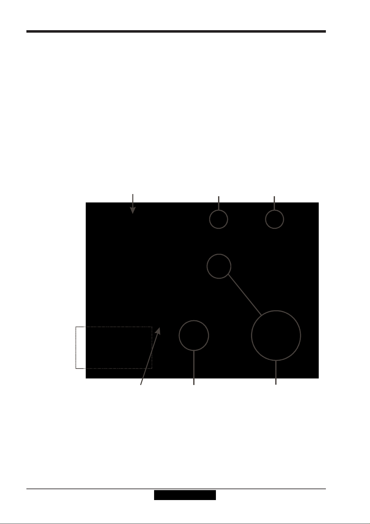
Chapter 1
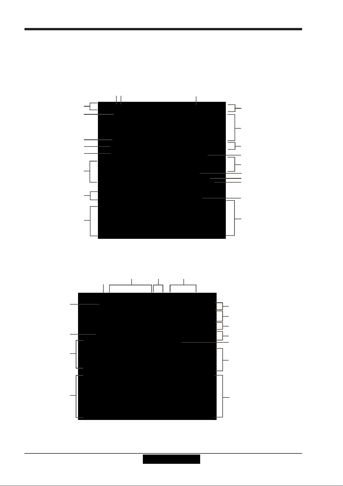
A
A
ALT Input Switch
Assignable R otary Scrollers
Meter View Switch
Q
C
Video & Talkback
Phones
Sol o 1 & 2 Controls
rs
rs
1.3 Before You Start
There are certain general operating principles and terms that should be understood before continuing to use this manual.
Please read this chapter carefully before proceeding.
1.3.1 Worksurface Layout..............................................................
Left & Right Sections
Input Gain and Phase
Rotary Resolution
2nd Function
Aux Scroll
Option/All
ssignable Rotaries and Switches
ux / Pan / Dynamics/FX Controls
Mute and Interactive LCD
Function Bu tt on
Channel Fade rs
Centre Section
High and Low Pass Filters
4 Band Dynamic Parametric E
Multiband Dynamics
Threshol ds & On / Off
Channel Inserts A & B On/Off
Direct Out On/Off
Dedicated Aux Rotari es
Joystick
Hard Mute & Full Safe
Channel Scroll & Undo/Redo
Layer Switch
Channel Fader Banks
A/B Engine Switch
Rotary Re solution
Screen Scrol l
Channel Fad ers/Mutes &
Graphic EQ Controls
LCD Function Buttons
hannel Faders/Mutes &
LCD Functi on Buttons
Dynamic Automation
Snapshot Controls
Monitoring Matr ix
Macros
Fader Flip
Channel Fader Banks &
Assignable M as ter Fade
Channel Fader Banks &
Assignable M as ter Fade
1-4

Chapter 1
1.3.2 Layers and Banks .................................................................
The SD7's worksurface is divided into Layers and Banks. Each Bank contains twelve channels, and the channels which are
currently active on the control surface are defined using the fader bank and bank layer buttons to the right of the Channel Strip
section’s faders:
A ‘bank’ is a set of twelve faders, and a ‘layer’ contains up to six ‘banks’. There are up to 3 ‘layers’ in each section of the desk,
allowing up to 216 channels to be accessible on each worksurface section.
Pressing the bank layer button, located above the fader bank buttons, toggles between layers.
To access a bank of faders within that layer, press the appropriate fader bank button. To switch all three sections of the
console to the same bank level, press and hold one of the fader bank buttons.
The specific channels which are contained within each Bank is defined in the Layout > Fader Banks display. By default, the
Input channels will be assigned to Layer 1 on the left and right sections of the console. The different output channels will be
assigned to Layer 2 and also to the upper centre section. Control Groups will be assigned to the lower centre section. These bank
assignments can be customised by the user and saved in a session at any time. Holding any bank or layer button down for a
couple of seconds will switch all 3 worksurface sections to the same bank level or layer.
1.3.3 Using the Control Surface ....................................................
There are two main ways in which all of the functions of the SD7 are accessed:
1. The touchscreen display, which can be controlled directly using a finger, or by using the keyboard and mouse
2. The physical encoders, switches and faders.
Note that when touching the screen directly, you may find it easier to use a finer point than your finger.
However, in order to prevent damage to the screen, it is important that you only use devices specifically
designed for touching screens (such as a pda stylus), and that you never press down hard on the screen.
A number of functions can be accessed in different ways, allowing users to operate the console using whichever interface they
prefer. This manual will describe accessing on-screen functions by touching the screen directly and not by using the mouse.
All of the physical controls found in the centre section are described in full within the relevant section of the manual and many
require no further introduction. The Master screen has a row of grey buttons which are used to access a range of configuration
displays. Pressing these buttons opens either a further drop-down sub-menu or a pop-up display. If a drop-down menu is
opened, pressing on one of its entries will open a pop-up display. The buttons lighten to indicate that their sub-menu or pop-up
display is open. A number of the buttons within each pop-up display generate further pop-ups.
The buttons within the pop-ups are coloured grey when their function is inactive, generally switching to a lighter shade of the
pop-up background when their function is active. Pressing on a text box opens a numeric or QWERTY keypad which can be
operated directly by pressing the screen or via the console’s external keyboard.
Pop-ups are closed by pressing the box in the top right-hand corner of the pop-up, marked CLOSE or CANCEL (or by pressing CAN on keypad pop-ups).
1-5

Chapter 1
To the right of the Master Panel is a single encoder marked Touch-Turn (shown below). This is used to access any rotary
controls within the Master Panel. To assign the Touch-Turn encoder to a particular on-screen pot, touch the pot to be assigned.
You will notice that a coloured ring appears around the on-screen pot, indicating that it is assigned to the Touch-Turn encoder.
The colour of this ring is unique to that control, and is also reflected in the base of the Touch-Turn encoder, providing further
indication of which pot is currently assigned to it.
1.3.4 The Assigned Channel .........................................................
One of the channels in the Channel Strip panel is displayed in gold, indicating that it is currently the Assigned Channel. This means
that it has been assigned to the worksurface controls and can be configured in detail, as described below. To Assign a channel,
touch anywhere in the channel on the screen except the Aux Send area of the input channels. Alternatively, use the ch left and
right buttons at the bottom of the channel worksurface controls to scroll through the channels in the panel:
Note that these left and right arrows are duplicated in the channel Setup and Output displays.
Note also that the Select Channels display provides another method for assigning a channel to the
worksurface controls.
Once a channel is Assigned, all of the controls for that channel which are not displayed within the channel strip itself can be
accessed via secondary pop-ups, displayed by touching inside the relevant area of the channel. These pop-ups include controls
such as input and output routing and signal processing parameters.
A number of the physical rotary encoders on the control surface can be assigned to different on-screen pots. In order to ensure
that it is clear which function is assigned to which encoder, the assigned on-screen pot will have a coloured ring around it which
will be reflected in the colour of the light around the base of the encoder on the control surface.
The twelve encoders and buttons immediately above the Channel Strip panel (shown above) refer to the channels with which
they are aligned. These controls are concerned with the channel input, located at the top of the Channel Strip panel.
The three rows of encoders and buttons immediately below the Channel Strip also refer to the channels with which they are
aligned. Normally, these control the level and on/off status of the three highlighted aux sends, but can have a number of functions
assigned to them. Touching on an aux send on the screen will assign that aux and the ones immediately below it to the aux
encoders. Six aux sends can be displayed in the Channel Strip panel at any one time. If more than six aux sends have been
1-6

Chapter 1
created in the session, the scroll button outside the bottom left-hand corner of the screen can be used to scroll the display
through the remaining auxiliaries:
The controls to the right of the Channel Strip panel allow the Assigned channel to be adjusted:
The top half of the channel worksurface controls (down as far as the insert a, insert b and direct buttons, as shown above)
control the signal processing parameters which are displayed in the pop-ups accessed by touching in the appropriate section of
the active channel. The bottom half of the channel worksurface controls is concerned with output routing.
To the left of the Channel Strip panel are more channel controls: When pressed, the 2nd function button allows access to different parameters:
1) Stereo Aux Pan and Pre/Post switching
2) Hard Mute of a channel
3) Switching of LR or LCR panning
4) Fine adjustment of Delay settings on output channels
The Option/All button has 2 main functions:
1) When pressed and released, any channel that is a member of a gang will be temporarily isolated from that gang.
2) When pressed and held, any parameter that is adjusted on a single channel will also be adjusted in the same way on all
of the channels in that bank
1.3.5 The Master Fader..................................................................
By default, the lower master faders are both assigned to the master group output, which is the lowest stereo group output by
default. In addition, the master faders can be assigned to the solo buss outputs. The ASSIGN FADERS function can be used to
assign any other function to these faders.
1-7
Chapter 1
Inputs
R
Groups
Auxes
Matrix
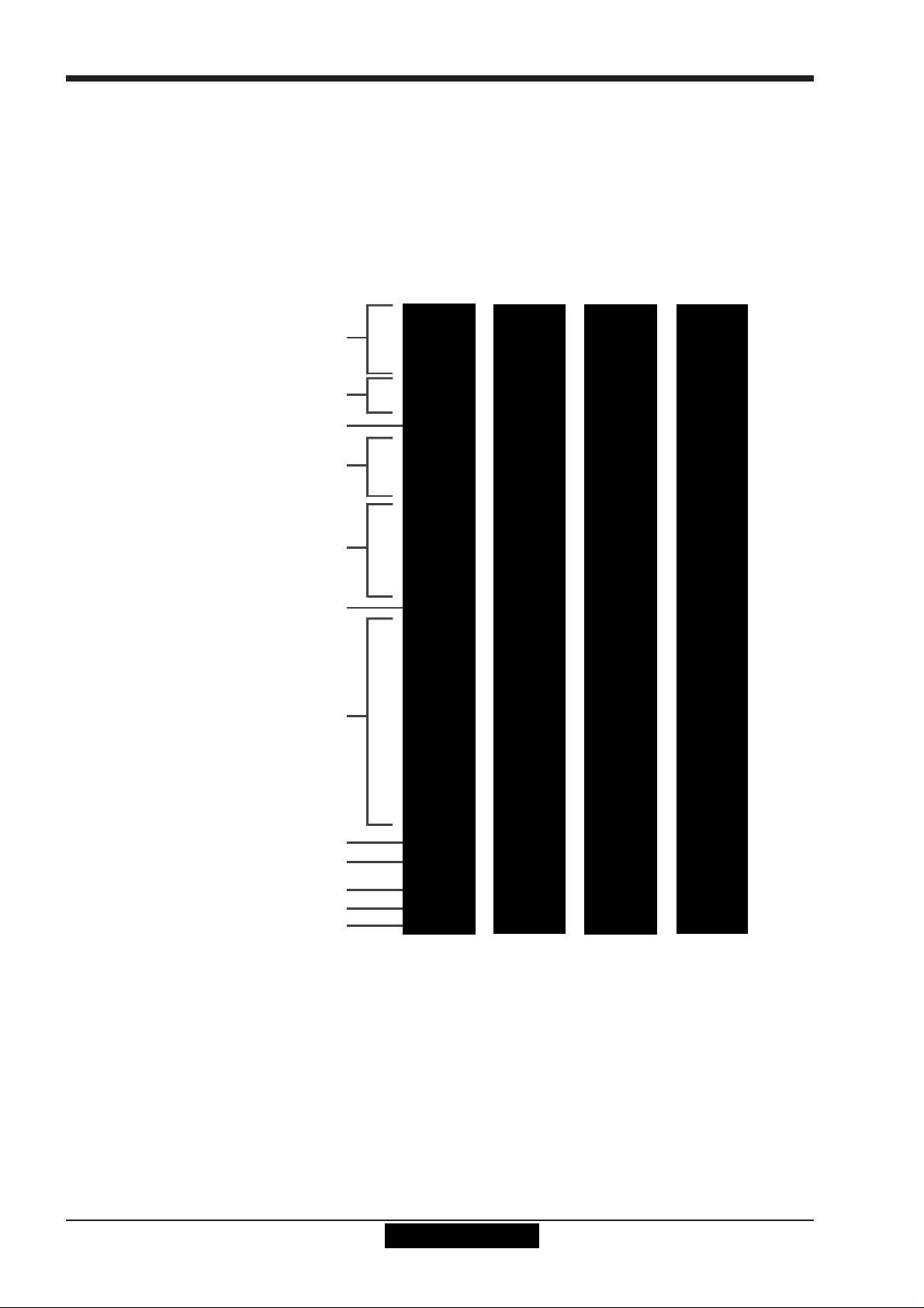
1.3.6 Channel Types ......................................................................
The SD7 has 4 different channel types which are laid out in banks of 12 on the console worksurface and can be identified by their
colour.
By default, the Input Channels will be assigned to Layer 1 on the left and right sections of the console.
The output channels (Groups, Auxes and Matrices) will be assigned to Layer 2 and also to the upper centre section.
Control Groups will be assigned to the lower centre section. These bank assignments can be customised by the user and saved
in a session at any time.
Holding any bank or layer button down for a couple of seconds will switch all 3 worksurface sections to the same bank level or
layer.
The controls on each different type of output channel are identical but an input channel has a number of additional features.
Input Module - Touch to Expand
Analogue Gain/Dig ital Trim
Phase - Gain Tracking
Main/Alt Input Select
HPF/LPF
Insert A Routing & On/Off
4 Band Dyna m ic EQ
Touch To Expand
Multiband Dynamics
Touch To Expand
Insert B Routing & On/Off
Touch to As sign Rows
outing Module - Touch to Expand
Gang & Safe Indicators
Aux Send s
Channel Pan
Mute & Hard Mute
Channel Label
1-8
Chapter 1
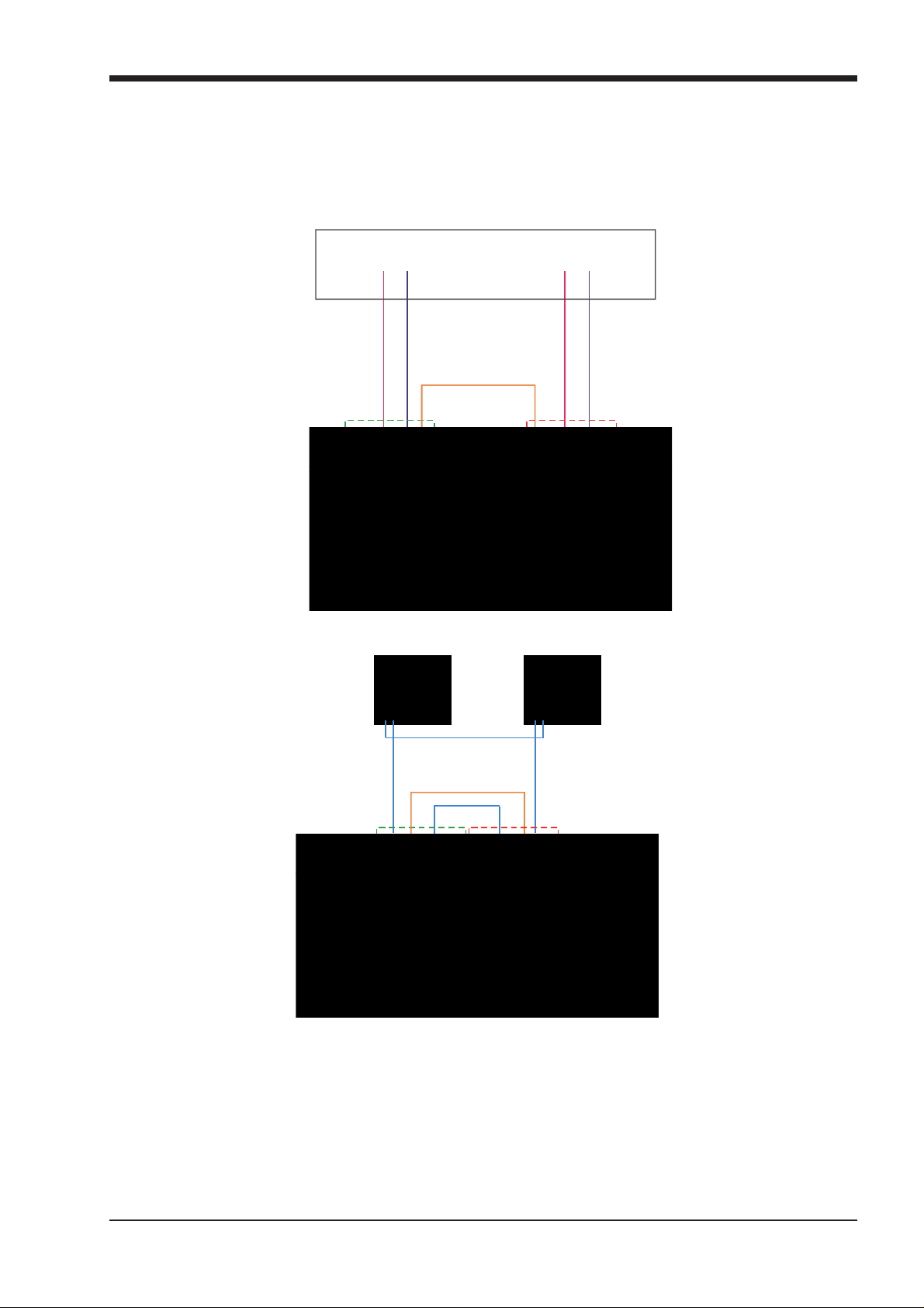
CONNECTION WITH MADI
1.4 Hardware Configuration
1.4.1 Connections ..........................................................................
Detailed information on the various systems of connection is provided in the relevant chapter of this manual but the following
diagram provides an overview of a single console/single rack setup.
DiGiRack
AUX MADI IN
MAIN MADI IN
MAIN MADI OUTAUX MADI OUT
ENGINE B
T
U
N
I
O
A
A
1
1
T
T
R
R
O
O
P
P
I
I
D
D
A
A
M
M
B
E
N
I
G
N
E
Ethernet Crossover Cable
B
E
N
I
G
N
E
T
U
O
A
1
T
R
O
P
I
D
A
M
A
E
N
I
G
N
E
CONNECTION WITH OPTICAL FIBRE
OPTO A
OPTO A
OPTO B
OPTO B
ENGINE A
OPTO A
OPTO A
ENGINE B
OPTO B
OPTIONAL
REDUNDANT
LOOP
Ethernet Crossover Cable
OPTO B
N
I
A
1
T
R
O
P
I
D
A
M
A
E
N
I
G
N
E
ENGINE A
All connections should be made before switching on the console and racks.
The console and rack each have dual redundant power supplies and both should be switched on at all times. After switching on
the console the software will be launched automatically and the state of the worksurface and settings should be the same as
when it was last Shut Down.
To Shut Down the console press the System>Shut Down button and wait until you receive a message saying that it is safe to
switch the power off.
The SD7 worksurface has 12 analogue I/O and 12 AES I/O on its rear panel (referred to as Local I/O) and additional I/O is supplied
in the form of remote DiGiRacks which can each accommodate up to 56 inputs and 56 outputs in different formats. These racks
are connected to the worksurface by either 100M high specification 75 Ohm coaxial cables fitted with BNC connectors or optical
fibre. The DiGiRacks have two pairs of MADI connectors - Main MADI IN & OUT and AUX MADI IN & OUT.
1-9
Chapter 1
Graphical representation of connected rack
In normal operation the MADI connections should be as follows (see diagram above):
Rack MAIN MADI IN connected to the console MADI 1A OUT
Rack MAIN MADI OUT connected to the console MADI 1A IN
Note - Optionally, a second set of MADI cables can be connected to provide MADI redundancy from the
rack's AUX MADI ports to the console's MADI 1B ports
The console's other MADI Ports can be connected to a MADI recorder( See Audio I/O Panel for setup details) or a second DiGiCo
Rack or console.
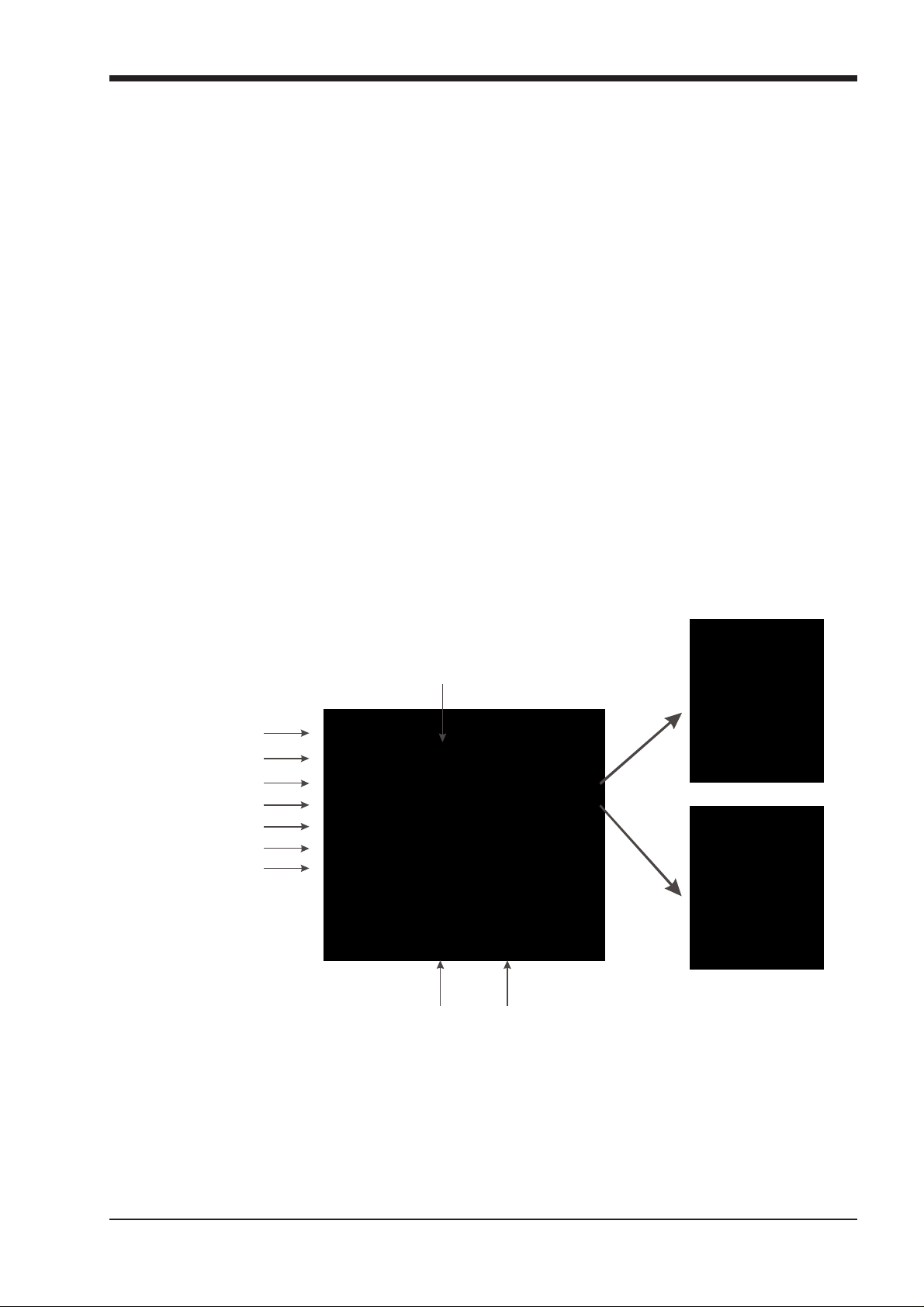
1.4.2 Audio I/O Panel.....................................................................
The Audio I/O window is used to configure the physical I/O connected to the SD7, including configuring and naming the sockets of
the option cards installed in racks, and the setting of Pads and phantom power.
Local I/O : The SD7 provides local audio I/O via 3 cards installed in the rear of the console. These operate independently of
connected racks, providing additional audio I/O.
To access the SD7 Audio I/O Setup Touch “Setup” on the Master Screen, followed by “Audio I/O”
The Audio I/O window that opens is divided up into 4 sections:
Port selection
&
Global Shared controls
Port properties
&
Port Shared controls
The left side of the window shows the ports. Each port relates to an available physical audio connection (Local IO, MADI Ports or
Optocore connections).
The section immediately to the right of the this contains the controls relating to the ports. When a port is selected, this section
changes to reflect the status of the selected port, and allows it’s configuration to be changed as required.
The right hand section of the Audio I/O Window shows a graphical representation of the rack configuration connected to the
selected port. Depending on the port selected, the graphic will change, showing the available physical I/O. Each small “square” on
the image represents a single physical audio connection or socket, with these arranged in columns or rows, representing I/O
cards in racks, or the local I/O on the back of the SD7 console.
The section below the graphical rack picture allows configuration of the cards or slots and sockets, including custom naming,
phantom power and pad selection.
The local I/O configuration is fixed, so no hardware changes are possible. You can, however, change the Port Name, the Group
Names (relating to name of each physical card) and the Socket Names (the name of each physical connector on a card).
1-10
Card/Slot and Socket Options

Chapter 1
1.4.3 Creating Ports for Optocore Racks ......................................
If two SD7s are sharing racks with Optocore connections, it is essential that different Optocore IDs are allocated to each engine in
the system. The Optocore ID is set at the top of the on screen Network panel and should be as follows:
First console A Engine = OPTO ID 0 - This engine can output to Optocore racks
First console B Engine = OPTO ID 1 - This engine can output to Optocore racks
Second console A Engine = OPTO ID 2 - This engine cannot output to Optocore racks
Second console B Engine = OPTO ID 3 - This engine cannot output to Optocore racks
The default Port list will not contain any Optocore ports, only the 4 MADI ports and Local I/O. If you are using Optocore connected racks you first need to add an Optocore port by pressing the Add Port button. This will provide a 5th port named 5:Rack 5 and in the Connection drop down you will see that the port is automatically defined as being used by a rack on Optocore ID30 connected to Optocore Loop 1. This setting is normally correct for a single Optocore connected Stage rack but you may need to check the rack's Optocore ID by interrogating the rack itself.
The default Port name can be changed by editing it in the Port Name box on screen.
1.4.4 Checking/Adjusting Optocore Rack ID ...............................
On the rack itself, locate the 4 small white buttons below the LED display. The first 2 buttons are Page Up/Down and the 3rd and
4th buttons are Data Up/Down. First hold the two Data buttons down together to unlock the paging function and then press the
Page Up button once. This will display the Optocore ID number for the rack. In DiGiCo D-Series consoles this would normally be
ID30 for Stage Rack 1 and ID32 for Stage Rack 2, so if the rack is being shared with a D5 or D1 it is important to keep the ID
numbers consistent with this.
If you need to change the Optocore ID for the rack, press the Data Up/Down buttons to select an ID in the possible range from
ID30 to ID33. This should be matched with the Connection details in the drop down menu on the SD7 Audio I/O panel.
1.4.5 Rack Connections.................................................................
With a Rack selected in the left hand port selection list, the window will change to look something like the image below, depending
on the cards installed in the connected rack. The graphic shows the 14 available cards/slots, 7 input & 7 output.
1-11
Chapter 1
Edit the Port Name here.
Eg. Stage Rack, Local Rack etc...
AES Input So cket with
Analogue Line Out
E
S
In order to use the rack, the on-screen contents of the rack must match the cards physically installed in the rack connected. There
are two ways of achieving this :
Manual Conforming of Rack :
Select each card (column) and manually select the appropriate card in the Card/Slot Type drop down menu in the lower section of
the window. Once the correct card type is selected, the Label at the bottom the selected card will turn green, indicating the card
type matches the card installed in the rack. If the Card Type name is Red, then there is a mismatch, and the error should be
corrected by selecting the correct card type.
Automatic Conforming of Rack :
Just below the rack view section of the window is the auto-conform all button. Pressing this button will correctly select the correct card for each slot of the connected rack. Once complete, all of the Card Labels beneath each slot should turn green.
It is also possible to auto-conform on a card-by-card basis. With a single card selected (by touching any of the sockets on that
card), press the auto-conform button next to the Card/Slot type button selector in the lower section of the window. This will
automatically match the Card/Slot type for the connected rack.
Copying Audio and Listening to Copied Audio (MADI Recorder Setup)
Any incoming MADI stream can be copied to any other MADI Output by selecting the incoming Port in the Ports list and using the Copy Audio To drop down menu. For example, if you want to copy Rack 1's Audio Inputs to a MADI equipped recorder connected on Port 2, select Port 1 in the ports list and then select MADI 2 from the Copy Audio To drop down menu.
The console will send the 56 channel MADI stream to MADI Output 2 and it can be recorded as necessary.
In addition, by connecting the recorder's MADI Output to the console's MADI 2 Input, the playback can be monitored in the same
channels as the original source material. Just press the Listen To Copied Audio button to monitor playback and press it again to
return to monitoring the live sources from the rack.
dit Global or Individual Rack
hared status...
SRC switched off
Socket wit h -1 0db Pad
Standard MADI Connections
If you have a standard MADI connection (not a DiGiCo DiGiRack) to your SD7, you can set the console to display the MADI with
generic signal names, i.e. MADI 1, MADI 2.. etc. through to MADI 56 instead of the usual rack style names. The naming does not
affect the signal, but makes routing signals easier.
Console to Console routing
If two SD7 consoles are connected together using MADI or Optical fibre, it is possible to route audio and video between them. By
default, Port 4 is defined as a Console connection.
There are 48 bidirectional audio paths between the two SD7’s. The last 8 channels worth of audio are occupied by a video/text
messaging feed. This could be the built-in Camera, or an external video input.
1-12
Auto-Conform All function automatically conform s ent ire
rack...
Select Ca rd Type manually or
using Auto-Conform function,
and edit Group Name
Selected Socket Properties
Edit Name and Socket options.
Chapter 1
busses
S
S
Set Order of Aux and
Isolate / Receive Only / Full Control
In multi-console system where DiGiRacks are connected with MADI and shared between two DiGiCo Consoles, only one of the
consoles can take control of the rack, with respect to Gain, Phantom Power and Pads. To overcome this, it is possible to place
each SD7 into one of 3 states of operation; Isolate, Receive Only or Full Control.
These three states can be set individually, on a per rack basis, or globally for all shared racks. Isolate : The SD7 will not communicate with the rack and therefore any adjustment of input gain or +48V switch will have no
effect on the rack settings
Receive Only : The SD7 will receive the rack’s existing settings but will not be able to control the gain etc on the racks. Full Control : The SD7 will send its settings to the racks and change them accordingly.
1.5 Configuring a Session
The SD7 has a default setup which means that the new user need not get involved in configuring the desk at this stage. However,
here is a brief overview of how the different displays are used in putting together a session. Each of the master displays introduced below are described fully within the rest of the manual.
The Setup > Audio IO display is used to configure the physical I/O connected to the SD7, including configuring and naming the
sockets of the option cards installed in racks, and the setting of pads and phantom power. (See previous section)
The File > Session Structure display is used for configuring how the console’s the DSP channels are to be divided between channel types, and where the format of the channels is defined.
The Session Structure display can be used to automatically assign the channels to the worksurface. However, channels can
also be manually added to the worksurface using the Layout > Channel Faders display.
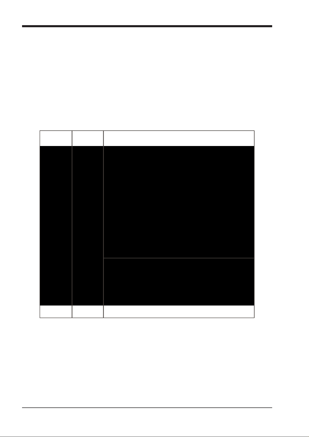
1.5.1 Session Structure..................................................................
When starting a new session, it is important to decide how many of each type of channel is required. While changes to session
structure can be made once a session has been started, it is best to try and set these parameters before configuring the session.
The structure will set items such as the number of input channels, the number and type of aux channels, group channels and
matrix channels available.
Group bus se s
Touc h number ’s to
edit with pop-up
keypad or touchturn
Enter Session title
Set number of Input Channels
Set number and type of Aux
et number and type of G roup
Set number of Matrix Inputs
Set number of Matrix Outputs
et number of Control Groups
Total number
of unallocated
processing
There are a total of 254 processing channels available, 124 of which can be busses (output channels). These channel resources
can be split into input or output channels in almost any configuration.
The default configuration is :
72 input channels
6 Mono Aux busses & 6 Stereo Aux busses
6 Mono Group busses & 6 Stereo Group busses
16 Matrix Inputs and 12 Matrix Outputs
24 Control Groups
To adjust any of the channel allocations, touch on the associated channel count box, and either enter a number using the pop-up
number keypad, or adjust using the assigned touchturn controller.
Total number
of spare
1-13

Chapter 1
L
It is worth remembering that each output (buss) allocated also uses up one of your processing channels. So if, for example, you
were to allocate all 124 busses, this would leave you with a maximum of 132 input channels.
Clear All Buttons : When changing routing, you have the option of clearing any non-default routing or processing (EQ, dynamics etc) from the channels in the session. This is especially useful when restructuring an existing session to make a new session. The clear snapshots, clear automation and clear macro’s perform similar operations.
Rebuild Banks : When changing the number of allocated channels in any section (input channels, busses etc), there are two possible scenarios. If you restructure the session without rebuilding banks, any additional channels you have allocated are not “placed” on the worksurface, and need to be manually assigned to faders. If however, you restructure a session with Rebuild Banks enabled, the worksurface will be built with all channels available on the worksurface.
Aux Sends and Direct Sends : By toggling the state of the Aux Sends and Direct Sends Buttons in the Input Channels section, it
is possible to change the default operation of the Aux Sends and Direct Sends. These functions toggle between “Post Fader”,
“Pre-Fader” and “Pre-Mute”.
Aux Order and Group Order : The Aux Order and Group Order buttons open a second window, providing you with the ability to
change the order of auxes and groups. By default, mono busses come first, followed by stereo busses. The Master buss is the
first stereo buss, regardless of the order you place the busses in.
Auto-Route : The Auto-route functions automatically routes consecutive inputs for input channels, and consecutive outputs for busses. For example, auto-routing 72 inputs will route the first physical input (eg 1:Mic 1) to input channel 1, the second physical input (1:Mic 2) to input channel 2… until you either run out of inputs or channels. Auto-routes are as follows :
Input Channels auto-route with physical inputs
Aux, Group and Matrix Channels auto route to physical outputs
Matrix Inputs auto-route with group outputs
NOTE : Auto-Routing can only be used in conjunction with the “Clear All” button.
1.5.2 Assigning Faders to the Worksurface .................................
If, after a Session Restructure, you find that newly created channels do not appear on the worksurface, open the Layout/
Channel Faders panel on the Master screen and you will see a full list of all input and output channels that are present in the
session.
To assign channels to the worksurface, select a bank and press the LCD Function button.
Then press the LCD button labelled Assign Faders to enter that mode and press each of the LCD buttons for the channels that
you wish to assign.
Now press the first channel that you wish to assign on the Layout/Channel Faders list on the Master screen.
Consecutive channels will be assigned to the worksurface for each LCD button that is in Assign mode.
Now press the LCD Function button again and return to the standard mode by pressing the LCD button labelled Solo
Press LCD Functi on button
then Assign Faders
Press LCD button(s)
for Assignment
ayout/Channel Faders
Click down arrow
Touch first channel
Open
to expand list
to assign
1-14

Chapter 1
Enter a Filename
Enter a Descr iption
I
er
Select a File
File Details
I
d
1.6 Saving and Loading Sessions
1.6.1 Save As New File .................................................................
When you change the configuration of a session you should save it to the console's flash drive under a new filename.
If the Save Session panel has not appeared automatically after a session restructure then touch the Files button on the Master
screen and then press Save As New File.
Select the destination drive (Internal or Removable) and file path and then enter a new file name and description for the file - then
press the Save button.
Note: If you touch a session name on the existing list, this name will automatically be selected as the new file
name and touching Save will overwrite the old file.
Select Inte rnal or
Removable USB
nternal files saved
in D:\Projects
To create a new fold
in D:\P rojects
1.6.2 Save Session ........................................................................
This button which is found above the Save As New File button will save the existing session in the same location and under the
same file name as it was previously saved or loaded from. It therefore serves as a "Quick Save" option to update an existing
session.
Remember that this function will overwrite your last saved version. If you wish to save the session under a new name use the Files menu button and select Save As New File (See above).
1.6.3 Load Session ........................................................................
To load a previously saved session:
Touch the Files button on the Master screen and then press Load Session.
Select the source drive (Internal or Removable) and the required file from the list - then press the Load button.
Select Inte rnal or
Removable USB
nternal files saved
in D:\Projects
Press Loa
1-15

Chapter 1
1.7 Audio Sync
To access the Audio Sync Panel, touch the Setup Menu button, followed by Audio Sync. The following window will open…
The SD7 will operate at Sample Rates of either 44100Hz (44.1kHz) or 48000Hz (48kHz). By default, it is set to clock internally (as
a Master) at 48kHz.
Within a normal setup, the SD7 will usually remain as clock master. However, there are times when the SD7 needs to be clocked
externally. The Audio Sync panel allows you to control external synchronisation.
The SD7 will clock from the following sources : Word Clock, AES/EBU, Video Reference, MADI & Optocore
Note : When a valid clock is detected on an external sync input, the corresponding Green OK box will light, even if that input is not
selected as the clock source for the SD7.
Example External Clocking : Word Clock @ 48kHz
1-16

Chapter 1
Touch top of
Select or type
S
1.8 Routing Basics
1.8.1 Selecting Inputs & Outputs...................................................
All channel input, output, insert send and insert return routing is done via routing displays, accessed via the dark grey routing
buttons in the channel Setup and Output displays (shown below for an Input channel’s input).
To access Channel Input Setup, touch the top of an input channel display on the touchscreen.
To access Channel Output Setup, touch the bottom of any channel type's display on the touchscreen.
elect a Layer
Select a Bank
Mono/Stereo
Press Main Input
Label Channel
Input Channel
Select
Rack
Number of Inputs
to Ripple Route
Select
Card
Socket
Select
Within each display, there are three columns containing three levels of routing selection:
- The left-hand column contains the available ports within which the desired input or output might be located;
- The middle column, signal groups, then shows the available groups of inputs or outputs within that port;
- The right-hand column, signals, then displays the individual inputs or outputs available within that signal group.
The boxes in each column are lit blue to indicate that they are currently selected. If there is already a routing assigned within the
display, the port and signal group columns containing the current assignment will be half-lit.
Each output can only have one channel routed to it. The outputs that are currently in use by another channel display in blue text. If
you attempt to route a different channel to an output which is already in use, a confirmation box appears, indicating which channel
is already using it, and warning that continuing with the action will cause the old channel to be unrouted from this output. Press
Yes to proceed, No to cancel.
Note that when routing direct outs from Input channels or outputs from output channels, any number of
available signals can be selected. A new route selection will therefore be added to previous selections in
these cases. However, inputs, insert sends and insert returns can only route to/from one signal (in the case of
mono channels) or two signals (in the case of stereo channels). A new route selection will therefore result in
the previous selection being lost for inputs and insert sends and returns.
For stereo channels, left and right routes are presumed to be consecutive: When routing stereo signals, select the left route, and
the next signal in the list will be automatically selected as the right route. If the last signal in a signal group or port is selected as
the left route, the first signal in the following signal group or port will selected as the right route.
For input and insert return routing, the INTERNAL port provides the following signal groups:
Misc: The oscillator, white and pink noise generators.
Graphic EQs: The outputs of the SD7’s internal graphic EQ’s.
Effects: The outputs of any effects sends that have been created
Channels: The direct outputs from the other input channels
Groups: The outputs of the group busses
Auxes: The outputs of the auxiliary busses.
1-17

Chapter 1
Note: The outputs for the channel being routed are locked out of the signal list
Note also that the console views all routes as a single list. Therefore, if the left signal is connected to the last
signal in a port, the right signal, will be automatically connected to the first signal of the next port, regardless of port type.
For output and insert send routing, the INTERNAL port provides access to the inputs of the SD7’s Graphic EQ’s, and the inputs to
any effects that have been created.
The 0:Local I/O port contains a list of the inputs or outputs found directly on the SD7’s back panel. The Rack ports contain all of the inputs or outputs available within the remote I/O racks, as defined in the Audio I/O display Once a route has been selected, its name will appear below the routing button in the Setup or Outputs display. Whenever a route is created, metering and additional controls are made available below the routing button. These controls are
dependent on the type of route created, and are described in detail within Chapter 2 where necessary:
Local input routed to an input or insert return: a Line or Mic selector.
Line input routed to an input or insert return: no additional control.
Mic pre-amp routed to a mono input: a 48V button for remote control of phantom power, and delay controls.
Mic pre-amp routed to a stereo input: a 48V button, delay controls and pan controls.
Mic pre-amp routed to an insert return: a 48V button, phase reverse (Æ) button and gain trim.
Output routed to a console output: a -10db pad (rack out only), on button for switching the send on and off, gain trim
and send point selector which toggles the place within the channel from which
Insert send routed to a console output: a -10db pad (rack out only), on button for switching the send on and off, and trim.
Insert send routed to a graphic EQ: an on button for switching the send on and off
Output routed to a graphic EQ: no additional control.
the direct output is fed:
pre-F Pre-fader,
post Post-fader
pre-M Pre-mute (and pre-fader)
Buttons become ringed in either red or green to indicate that they are on.
1.8.2 Ripple Channels ...................................................................
The ripple channels function, located at the top of the route display, allows consecutive channel routes to follow the routing of the current display incrementally. For example, Channels 1 to 8 direct outputs can be routed to Rack 1 > Line outs 1 to 8 respectively by routing Channel 1’s direct out to Rack 1 > Line out 1 and allowing the ripple channels function to route Channels 2-8 automatically.
The number of channels to be rippled is defined either by selecting the appropriate grey numbered button, or by selecting the
keyboard button to the right of the numbered buttons, typing the required number of channels (8 in the example above) into the
numeric keypad which appears, and pressing OK. Once you have configured the ripple channels function, any routing action
will also effect the appropriate number of channels above the channel being routed.
The ripple channels function treats stereo channels as two channels. In other words, if Channel 2 in the above example is
stereo, the ripple channels function will route Channel 1 to Line out 1, Channel 2 Left and Right to Line outs 2 and 3, Channel 3
to Line out 4 etc.
1-18

Chapter 1
1.9 Presets
Presets are used for storing and recalling settings for channels, fx units, graphic EQs and the matrix. While each preset functions
slightly differently, this section provides a basic understanding of how to use the various preset displays:
The left-hand column of a preset display contains the available groups of presets, and touching one of these groups brings up
the list of presets within that group in the column to its right (name). The columns to the right of the preset name displays the
number of channels whose settings are included in the preset (chs) (Channel and Matrix presets only), the date and time it was
created or updated (notes), and whether or not it is locked (lock).
Note that a presets display will only list presets of the relevant type.
To recall a preset, touch the name of the group containing the preset you wish to recall, and then touch the preset’s name. The
recall scope buttons at the bottom of the some preset displays allow you to select which elements are recalled and which
elements remain unchanged. The buttons are included in the recall when they are lit.
To save the current settings as a new preset, touch the group in which you want the preset to be stored and press the new
button. The new preset is automatically named according to the preset type. To alter the preset’s name, type the new name using
the keyboard display that appears (or the external keyboard) then, if relevant, touch and edit the number of channels’ settings that
you want to store in the preset (the default is one channel). Now touch OK.
Note that pressing CAN in the keyboard display will cancel the display but create the new preset with its
default name.
To save the settings as an update of a previous preset, press update, touch the preset you wish to overwrite, and press Yes in the confirmation display which appears.
Note that when updating a previous preset, failing to press update will result in the preset you wish to
overwrite being recalled, and the settings to be saved being lost.
To create a new group of presets, press new group. A new group will be created, called group n, where n is the next available preset group number. To alter the group’s name, type the new name using the keyboard display that appears (or the external keyboard) and touch OK.
Note that pressing CAN in the keyboard display will cancel the display but create the new group with its
default name.
The edit name button allows preset names and group names to be edited, and the preset to be locked, preventing them from
being edited, overwritten, or deleted. The button lightens to indicate that it is active. To edit a preset’s name, make sure the preset
is unlocked (see below), activate the edit name button and touch the preset’s name. Type the new name in the keyboard display
and press OK. To edit a preset group name, activate the edit name button and touch the group name. Type the new name in the
keyboard display and press OK.
To lock the preset, activate the edit name button and touch the preset’s lock column. A grey padlock appears, indicating that the preset is now locked. Touching the lock again with edit name active unlocks the preset.
To delete a preset, press delete, touch the preset to be deleted, and press confirm. To delete a consecutive range of presets,
press delete followed by select range, touch the first and last preset to be deleted and press confirm. To delete one preset,
or a nonconsecutive range, touch each preset to be deleted and press confirm. To delete an entire group of presets, press
delete followed by select all, then press confirm.
1-19

Chapter 1
1.10 Naming Channels and Busses
A large number of elements within the SD7 can be custom named. Access to the naming facility is via black and white text boxes
with down arrow and keyboard buttons to their right, such as shown here:
To create a name manually, touch the text box or the keyboard symbol to its right to bring up a QWERTY keyboard display. This keyboard includes standard Caps, Shift and Delete functions, as well as Cut , Copy and Paste functions which can be used to move name text between channels. The arrow buttons in the bottom left-hand corner of the keyboard display move the cursor within the text box. Create the new name, either using the on-screen keyboard display or the external keyboard, and press OK. To close the keyboard display without changing the name, press CAN. To move the keyboard display to the following channel, press Next (or TAB on the external keyboard).
The Channel Name display enables commonly used words to be inserted quickly without the use of the keyboard. This facility is available not only when naming channels but also when naming other elements. To open the Channel Name display, touch the down arrow immediately to the right of the Setup display’s channel name text box.
Touching any word from the display inserts that word into the channel name text box. Further words can then be added to the
channel name in the same way, divided by a single space. Numeric and L/R identifiers can be added from the column down the
right-hand edge of the display. Text can be entered in CAPS or Initial Caps by pressing the CAPS and Initial Cap buttons in the
top of the display. If neither of these are selected, all text is inserted in lower case.
Note that the first text to be inserted from the Channel Name display when it is opened overwrites all previous text.
Note also that text that extends beyond the end of the text box will not be visible!
In addition to the standard word set, a list of user-defined words can be created and inserted by pressing the custom button,
located next to the Initial Cap button. The button lightens to indicate that the custom set is displayed.
To add a new word to the custom set, touch the box which you want to use and press edit, located next to the custom button, to bring up a QWERTY keyboard display. Type the required word and press OK. In this keyboard display, the Next button saves any text inserted in the current box and moves the keyboard to the next box in the custom list. To cancel the keyboard display, press CAN within the display, or press edit again. The words in the custom list are inserted into the channel name text box in exactly the same way as words in the standard list. Pressing custom again returns the display to the standard word set.
Tip: As custom names appear in the box in which they are typed, they are not automatically alphabetised.
The user may find it helpful to define a system for ordering the custom page.
Note also that the standard word set cannot be edited.
The current name can be cleared by touching the CLEAR button towards the top right-hand corner of the Channel Name display. The Channel Name display can be closed by touching the CLOSE box, in the top right-hand corner.
1-20

Chapter 1
and Dyamics
Q
1.11 Channel Processing
1.11.1 Dynamic EQ.........................................................................
The EQ section comprises four user-configurable parametric filters with Dynamic Control and a pair of swept High-pass and Lowpass filters.
The EQ is accessed by touching the on screen display to Assign the channel (the colour changes to yellow) and then using
the controls on the right hand side of the input module.
When a control is adjusted the expanded view seen below appears on the screen. This view can be seen at any time by touching
the EQ response graph on the screen.
NOTE: If the expanded view does not appear when a control is adjusted open the Options panel and set the
Auto Expand EQ option to Yes
To access the Dynamic control, touch the left arrow symbol on any EQ band.
Touching the normal EQ response graph will show an expanded view in a separate panel.
The order of EQ and Dynamics in the channel signal path can be changed using the worksurface button at the bottom of the EQ
section.
HPF/LPF
4 Bands
Dynamic E
Controls
Order of EQ
Note: The four band EQ and each of the filters have their own in/out switches.
The type of filter used by each band can be changed by successive presses of the Curve button for that band.
EQ Presets
1-21

Chapter 1
Single/Multband
1.11.2 Multiband Dynamics ...........................................................
The dynamics are accessed by touching the words Comp or Gate just below the EQ graph on screen to open the dynamics
panel.
Dynamics can function as a simple compressor and gate or a 3 way multiband compressor and gate according to the Multiband
button in the expanded dynamics panel.
The worksurface controls beneath the screen control the various parameters. Touching the Close button in the top right corner
of the panel will close it.
Dedicated Threshold, Gain controls and In/Out switches can be found on the right hand side of that section's worksurface.
These can control the Assigned channel's dynamics whether the on screen dynamics panel is open or not.
Comp Option
The Assignable encoders and switches beneath the screen can be assigned to any of the main dynamics controls. Hold the Assign Switch button on the left of the input section and touch the dynamics control required on the screen. The selected control is shown by the Status Display.
Dynamics Pres ets
1-22
Loading...