


 Loading...
SD Series Software Reference
SD Series Software Reference Manual
Software Reference Version A for Software Versions 5.0.680+
0-1

SD Series Software Reference
Copyright © 2014 Digico UK Ltd
All rights reserved.
No part of this publication may be reproduced, transmitted, transcribed, stored in a retrieval system, or translated into any language in any form by any means without the written permission of Digico UK Ltd. Information in this manual is subject to change without notice, and does not represent a commitment on the part of the vendor. Digico UK Ltd shall not be liable for any loss or damage whatsoever arising from the use of information or any error contained in this manual.
All repair and service of the SD products should be undertaken by Digico UK Ltd or its authorised agents. Digico UK Ltd cannot accept any liability whatsoever for any loss or damage caused by service, maintenance, or repair by unauthorised personnel.
Software License Notice
Your license agreement with Digico UK Ltd, which is included with the SD product, specifies the permitted and prohibited uses of the product. Any unauthorised duplication or use of Digico UK Ltd software, in whole or in part, in print or in any other storage and retrieval system is prohibited.
Licenses and Trademarks
The SD logo and SD name are trademarks, and Digico UK Ltd and the Digico UK Ltd logo are registered trademarks of Digico UK
Ltd. Microsoft is a registered trademark and Windows is a trademark of Microsoft Corp.
Digico (UK) Ltd
Unit 10
Silverglade Business Park
Leatherhead Road
Chessington |
|
Surrey |
|
KT9 2QL |
|
England |
|
Telephone: |
+44 (0)1372 845600 |
Fax: |
+44 (0)1372 845656 |
Email: |
sales@digiconsoles.com |
WWW:http://www.digico.biz
Manual Issue and Date: Issue A - 7th April 2014 - For Version 5.0.680+ Software
Licence Agreement
"Product": |
SD software product produced by Digico UK Ltd intended for use on Target Platform identified below. |
"Target Platform": |
Digico SD Digital Console systems. |
In return for the payment of the one-time fee, the Customer (identified at the end of this Agreement) receives from Digico UK Ltd a licence to use the Product subject to the following terms and conditions.
1.The Product may be used without time limit by the Customer on the Target Platform.
2.The Customer must register the Product with Digico UK Ltd. Registering the Product is deemed an acceptance of the terms and conditions in this agreement.
3.The Product and its licence are not transferable, and the Customer is not permitted to onward-license to any third party. The Customer indemnifies Digico UK Ltd against any and all claims and actions arising from third party use of copies of the Product made by the Customer.
4.The Customer agrees not to attempt to decompile the object code of the Product otherwise than in circumstances specifically provided for by law, and then only after consultation with Digico UK Ltd.
5.The Customer agrees not to use, or licence the Product for use, with equipment other than the Target Platform.
6.The Customer agrees not to modify the Product without the prior written consent of Digico UK Ltd.
7.This Agreement applies to any enhancement or upgrades that may become available for the Product.
8.This Agreement does not transfer any right, title, or interest in the Product to Customer except as specifically set forth herein.
9.Digico UK Ltd reserves the right to terminate this Agreement upon breach, in which event Customer shall thereafter only be authorised to use the Product to the extent that its contractual commitments to third parties require and then only where such commitments relate to use of the Product as authorised in the foregoing provisions of the Agreement.
LIMITED WARRANTY - Digico UK Ltd warrants for a period of 1 year from the date of purchase of the Product, the Product will reasonably execute its programming instructions when properly installed on the Target Platform. In the event that this Product fails to execute its programming instructions during the warranty period, the Customer's remedy shall be to return the Productto Digico UK Ltd for replacement or repair at Digico UK Ltd option. Digico UK Ltd makes no other express warranty, whether written or oral with respect of this Product.
LIMITATION OF LIABILITY - Except as otherwise expressly provided by law, (a) the remedies provided above are the Customer's sole and exclusive remedies and (b) Digico UK Ltd shall not be liable for any direct, indirect, special, incidental, or consequential damages (including lost profit whether based on warranty, contract, tort, or any other legal theory.)
This agreement is made under the Laws of England.
LICENCENO: .................... ..........................................................
REGISTRATION DATE: ..... ..........................................................
0-2

SD Series Software Reference
Contents
1.1 Introduction to Channel Types .............................................. |
.......1-2 |
1.2 Channel Input Setup - Common Elements ........................... |
.......1-2 |
1.2.1 Channel Strip Input Area ............................................... ....... |
1-2 |
1.2.2 Channel Delays .............................................................. ....... |
1-2 |
1.2.3 DiGiTube/Warmth ........................................................... ....... |
1-3 |
1.2.4 Naming Channels and Busses .................................... ....... |
1-3 |
1.2.5 Channel Safes ................................................................ ....... |
1-4 |
1.2.6 Copy Channels .............................................................. ....... |
1-4 |
1.2.7 Channel Presets ............................................................ ....... |
1-6 |
1.2.8 Channel Solos ............................................................... ....... |
1-7 |
1.3 Channel Output and Inserts - Common Elements ............... |
.......1-8 |
1.3.1 Channel Strip Output Area ............................................ ....... |
1-8 |
1.3.2 Channel Strip Insert Areas ............................................ ....... |
1-9 |
1.3.3 Console Output and Insert Routing ............................. ....... |
1-9 |
1.3.4 FX Presets .................................................................... ....... |
1-10 |
1.4 Input Channel Specific Functions ....................................... |
.......1-10 |
1.4.1 Trim and Track ............................................................. ....... |
1-10 |
1.4.2 Input Routing ............................................................... ....... |
1-11 |
1.4.3 Input Configuration ..................................................... ....... |
1-11 |
1.4.4 Channel Metering ......................................................... ....... |
1-12 |
1.4.5 Output Routing ........................................................... ....... |
1-12 |
1.4.6 Aux Busses and Assignable Controls ....................... ....... |
1-13 |
1.4.7 Group Outputs ............................................................. ....... |
1-14 |
1.4.8 Direct Outputs .............................................................. ....... |
1-14 |
1.5 Output Channels Specific Functions .................................. |
.......1-14 |
1.5.1 Unfolding Channels ..................................................... ....... |
1-14 |
1.5.2 Group Channels Specific Functions .......................... ....... |
1-15 |
1.5.3 Aux Channels Specific Functions .............................. ....... |
1-16 |
1.5.4 Matrix Channels Specific Functions .......................... ....... |
1-17 |
1.6 Channel Signal Processing .................................................. |
.......1-17 |
1.6.1 Channel Filters ............................................................. ....... |
1-17 |
1.6.2 Input Channel EQ ......................................................... ....... |
1-17 |
1.6.3 Output Channel EQ ...................................................... ....... |
1-20 |
1.6.4 Channel Dynamics ...................................................... ....... |
1-20 |
0-3

SD Series Software Reference
1.7 LCD Functions........................................................................ |
.......1-22 |
1.7.1 Introduction to LCD Functions ................................... ....... |
1-22 |
1.7.2 Solo ............................................................................... ....... |
1-23 |
1.7.3 Solo Choice .................................................................. ....... |
1-23 |
1.7.4 GANG ............................................................................ ....... |
1-23 |
1.7.5 JOIN CG ........................................................................ ....... |
1-24 |
1.7.6 Assign Faders .............................................................. ....... |
1-24 |
1.7.7 Unassign Faders ......................................................... ....... |
1-24 |
1.7.8 Swap Faders (SD5/SD7) ............................................. ....... |
1-24 |
1.7.9 Move Faders (SD5/SD7) .............................................. ....... |
1-25 |
1.7.10 Copy Bank From ........................................................ ....... |
1-25 |
1.7.11 Copy Bank To ............................................................. ....... |
1-25 |
1.7.12 Clear Bank .................................................................. ....... |
1-25 |
1.7.13 Create Multi ................................................................ ....... |
1-25 |
1.8 Multi Channels........................................................................ |
.......1-25 |
2.1 System Menu ............................................................................ |
.......2-2 |
2.1.1 Diagnostics .................................................................... ....... |
2-2 |
2.1.2 Oscillator ........................................................................ ....... |
2-2 |
2.1.3 GPIO Relays ................................................................... ....... |
2-2 |
2.1.4 Security .......................................................................... ....... |
2-3 |
2.1.5 Signal Over Indicators ................................................... ....... |
2-4 |
2.1.6 Overview Clear Screen .................................................. ....... |
2-4 |
2.1.7 Keyboard Help ............................................................... ....... |
2-4 |
2.1.8 F10: Reset FX ................................................................. ....... |
2-4 |
2.1.9 F11: Reset Engine ......................................................... ....... |
2-4 |
2.1.10 F12: Reset Surfaces .................................................... ....... |
2-4 |
2.1.11 Set Date & Time ............................................................ ....... |
2-4 |
2.1.12 Quit to Windows (SD5, SD7) ....................................... ....... |
2-4 |
2.1.13 Restart (SD5, SD7) ....................................................... ....... |
2-4 |
2.1.14 Shutdown ..................................................................... ....... |
2-4 |
2.1.15 Shutdown All ................................................................ ....... |
2-4 |
2.2 Files Menu ................................................................................. |
.......2-5 |
2.2.1 Templates ....................................................................... ....... |
2-5 |
2.2.2 Session Structure .......................................................... ....... |
2-5 |
2.2.3 Load Session ................................................................. ....... |
2-7 |
2.2.4 Save Session ................................................................. ....... |
2-9 |
2.2.5 Save As New File ........................................................... ....... |
2-9 |
2.2.6 Load Presets ................................................................ ....... |
2-10 |
2.2.7 Save Presets ................................................................ ....... |
2-10 |
2.2.8 Global Set To Defaults ................................................. ....... |
2-11 |
|
|
0-4 |
|

|
SD Series Software Reference |
|
|
|
|
|
|
|
2.2.9 Session Notes .............................................................. |
|
.......2-11 |
2.2.10 Session Report .......................................................... |
....... |
2-11 |
2.3 Layout Menu ........................................................................... |
|
.......2-12 |
2.3.1 Fader Banks ................................................................. |
....... |
2-12 |
2.3.2 The Overview Display .................................................. |
....... |
2-13 |
2.3.3 Channel List ................................................................. |
....... |
2-13 |
2.3.4 Set Spill ......................................................................... |
....... |
2-15 |
2.3.5 Transport Control ........................................................ |
....... |
2-15 |
2.4 Snapshots Menu .................................................................... |
|
.......2-16 |
2.4.1 Storing a Snapshot ...................................................... |
....... |
2-16 |
2.4.2 Recalling a Snapshot .................................................. |
....... |
2-16 |
2.4.3 Replacing a Snapshot ................................................. |
....... |
2-17 |
2.4.4 Editing Multiple Snapshots |
......................................... ....... |
2-17 |
2.4.5 Moving a Snapshot ...................................................... |
....... |
2-17 |
2.4.6 Renaming a Snapshot ................................................. |
....... |
2-17 |
2.4.7 Renumbering Snapshots ............................................ |
....... |
2-18 |
2.4.8 Deleting a Snapshot .................................................... |
....... |
2-18 |
2.4.9 Snapshot Undo ............................................................ |
....... |
2-18 |
2.4.10 Snapshot Groups ...................................................... |
....... |
2-18 |
2.4.11 Global Recall Scope .................................................. |
....... |
2-20 |
2.4.12 Individual Snapshot Recall Scope .......................... ....... |
2-20 |
|
2.4.13 Snapshot Recall Times ............................................. |
....... |
2-21 |
2.4.14 Snapshot Crossfades ............................................... |
....... |
2-22 |
2.4.15 Snapshots and MIDI .................................................. |
....... |
2-22 |
2.4.16 MIDI Devices ............................................................... |
....... |
2-23 |
2.4.17 MIDI Program and MIDI List ....................................... ....... |
2-23 |
|
2.4.18 Snapshot GPO Relays....... |
2-24 |
|
2.4.19 Surface Offline & Snapshot Editing (Not SD11) ...... ....... |
2-25 |
|
2.4.20 Auto Update ............................................................... |
....... |
2-25 |
2.4.21 Snapshots & MTC ...................................................... |
....... |
2-25 |
2.4.22 Snapshot Notes ......................................................... |
....... |
2-26 |
2.4.23 Snapshot Locked ...................................................... |
....... |
2-26 |
2.5 Options .................................................................................... |
|
.......2-27 |
2.5.1 Surface ......................................................................... |
....... |
2-27 |
2.5.2 Faders ........................................................................... |
....... |
2-28 |
2.5.3 Solo ............................................................................... |
....... |
2-29 |
2.5.4 Delays ........................................................................... |
....... |
2-30 |
2.5.5 Disable .......................................................................... |
....... |
2-30 |
2.5.6 Brightness .................................................................... |
....... |
2-31 |
2.5.7 Meters ........................................................................... |
....... |
2-31 |
|
|
|
|
|
0-5 |

SD Series Software Reference
2.5.8 Console ........................................................................ |
.......2-32 |
2.5.9 Status ............................................................................ ....... |
2-33 |
2.6 FX ............................................................................................. |
.......2-34 |
2.6.1 The Master FX Display ................................................ ....... |
2-34 |
2.7 Matrix Menu ............................................................................ |
.......2-35 |
2.7.1 The Matrix Panel .......................................................... ....... |
2-35 |
2.8 Graphic EQs Menu ................................................................ |
.......2-37 |
2.8.1 Graphic EQ Panel......................................................... ....... |
2-37 |
2.8.2 Ganging Graphic EQs .................................................. ....... |
2-37 |
2.8.3 Graphic EQ ALL Button ............................................... ....... |
2-38 |
2.8.4 Graphic EQ Presets ..................................................... ....... |
2-38 |
2.9 Control Groups....................................................................... |
.......2-39 |
2.9.1 The Master Control Groups Display ........................... ....... |
2-39 |
2.9.2 Control Group Fader Modes ....................................... ....... |
2-40 |
2.9.3 Control Group Mute Functions ................................... ....... |
2-41 |
2.10 Solos Menu ........................................................................... |
.......2-41 |
2.10.1 The Solo Panel ........................................................... ....... |
2-41 |
2.10.2 The No Solo Setup Display ....................................... ....... |
2-42 |
2.10.3 Assigning Solo Busses to Faders ............................ ....... |
2-43 |
2.10.4 Solo Outputs Routing ............................................... ....... |
2-43 |
2.10.5 Headphone Outputs .................................................. ....... |
2-43 |
2.10.6 Solo Meters ................................................................ ....... |
2-43 |
2.10.7 Solo As an Input Source ............................................ ....... |
2-43 |
2.11 Network and Mirroring ........................................................ |
.......2-44 |
2.11.1 Network Configuration .............................................. ....... |
2-44 |
2.11.2 Mirroring for the first time .......................................... ....... |
2-44 |
2.11.3 Mirroring Mode ........................................................... ....... |
2-45 |
2.11.4 Mirroring with a laptop PC ......................................... ....... |
2-45 |
2.13 Setup Menu ........................................................................... |
.......2-46 |
2.13.1 Audio I/O ..................................................................... ....... |
2-46 |
2.13.2 Port Selection ............................................................. ....... |
2-46 |
2.13.3 Port Hardware Configuration ................................... ....... |
2-47 |
2.13.4 Port Control ................................................................ ....... |
2-47 |
2.13.5 The Socket Display .................................................... ....... |
2-47 |
2.13.6 Socket Conforming ................................................... ....... |
2-47 |
2.13.7 Group and Socket Names ......................................... ....... |
2-48 |
2.13.8 Socket Options .......................................................... ....... |
2-48 |
2.13.9 Copy Audio ................................................................. ....... |
2-49 |
|
|
0-6 |
|

SD Series Software Reference |
|
|
|
|
|
2.13.10 Audio Sync ............................................................... ....... |
2-50 |
2.13.11 Timecode & Transport ............................................. ....... |
2-50 |
2.13.12 Macros ...................................................................... ....... |
2-51 |
2.13.13 The Macro Editor ..................................................... ....... |
2-52 |
2.13.14 Talkback ................................................................... ....... |
2-54 |
2.13.15 Text Chat (SD5, SD7) .............................................. ....... |
2-55 |
2.13.16 Video Link (SD7 Only) ............................................. ....... |
2-56 |
3.1 Console Audio Connections .................................................. |
.......3-2 |
3.2 Multi-Console setups............................................................... |
.......3-2 |
3.2.1 FOH & Mons sharing a stage DiGiRack (MADI) .......... ....... |
3-2 |
3.2.2 FOH & Mons sharing a stage SD Series Rack (MADI) . ....... |
3-3 |
3.2.3 FOH & Mons sharing DiGiRacks (Opto V220) .............. ....... |
3-4 |
3.2.4 FOH & Mons sharing SD Series Racks (Opto V221) ... ....... |
3-5 |
A1.1 Optocore V221 - Introduction ................................................... |
A1-4 |
A1.1.1 System Overview ...................................................... ....... |
A1-4 |
A1.1.2 Opto V220 (DiGiRacks) and Opto V221 (SD Racks) ....... |
A1-5 |
A1.1.3 Replacing DiGiRacks with SD Racks ..................... ....... |
A1-5 |
A1.1.4 Replacing SD Racks with DiGiRacks ..................... ....... |
A1-7 |
A2.1 The Audio IO Panel .............................................................. |
.......A1-8 |
A2.1.1 Layout ....................................................................... ....... |
A1-8 |
A2.1.2 Quick Start Guide for SD V370+ and Optocore V221....... |
A1-8 |
A2.1.3 Audio Sync .............................................................. ....... |
A1-12 |
A2.1.4 The Port List ........................................................... ....... |
A1-12 |
A2.1.5 Managing Ports ...................................................... ....... |
A1-12 |
A2.1.6 SD Rack Splits ........................................................ ....... |
A1-13 |
A3.1 SD Series Dual Loop Optocore Systems ...................... |
.......A1-13 |
A3.1.1 Important Considerations ...................................... ....... |
A1-13 |
A3.2.1 Setting up a Dual Loop System ............................ ....... |
A1-14 |
A3.2.3 Console Snd/Rcv Ports ......................................... ....... |
A1-14 |
A3.2.4 Single Loop Console on Loop 2 ........................... ....... |
A1-15 |
0-7

Chapter 1 - Channel Types
SD Series Software Reference
Chapter 1:
Channel Types and Functions
1-1

Chapter 1 - Channel Types
1.1 Introduction to Channel Types
This chapter describes all of the functions available within the SD channel strips. The first two parts of the chapter will examine the Input/Setup and Output sections of each of the types of channel strip, and the third part will cover the in-channel signal processing, which functions in precisely the same way on each channel type. Those elements which are common to each channel type are dealt with first, and then those elements which are specific to a channel type are dealt with separately.
In order to understand this chapter, you will find it helpful to have read the "Getting Started" manual for your console.
1.2 Channel Input Setup - Common Elements
1.2.1 Channel Strip Input Area .....................................................
The channel strip input section is located at the top of the channel strip (shown below for an Input channel). This is where the channel inputs, snapshot safes, and solo bus feeds are configured. Some basic controls are displayed in the channel strip.
However, most of the input parameters are contained in the channel Setup display, accessed by touching the channel’s input or filters areas at the top of the screen. The Setup display also contains a number of channel configuration elements.
Note that channels without an external input selected display a simpler input section than that shown here. Note also that input channels can display a channel meter which hides the input and filters sections of the channel strip. Press the 'assign' down button to close the meter view.
The large pot at the top of the input area of the main channel strip controls the input level, and can be accessed using the encoder immediately above the channel strip (SD7,8,10) or using the "quick select" buttons (SD 5, 9,11). For Input channels which have ADC’s assigned to their inputs, this remotely controls the analogue gain of the mic pre-amp in the I/O rack. For all other input types, this is a digital level trim. The gain value is displayed to the right of the level pot.
To the left of the pot there is a phase reverse button which is grey when inactive and red when switched in.
1.2.2 Channel Delays .....................................................................
Delay controls are found in the Setup display. The delay can be switched on using the on button, which is ringed in red to indicate that it is on. The left-hand blue pot controls the course delay amount in milliseconds. The right-hand blue pot enables fine adjustments to be made to this amount, measured in samples. Both pots can be assigned to encoders by touching the on screen control.
It is also possible to enter a specific delay amount using a numeric keypad. To do this, touch the keypad symbol to the right of the delay on button in the Setup display, select the desired units from the buttons to the right of the number buttons (seconds, feet, metres, frames or bpm) enter to amount using the keypad, and press OK.
Note that altering the delay units in this keypad display will change them wherever they appear on the console.
1-2
Chapter 1 - Channel Types
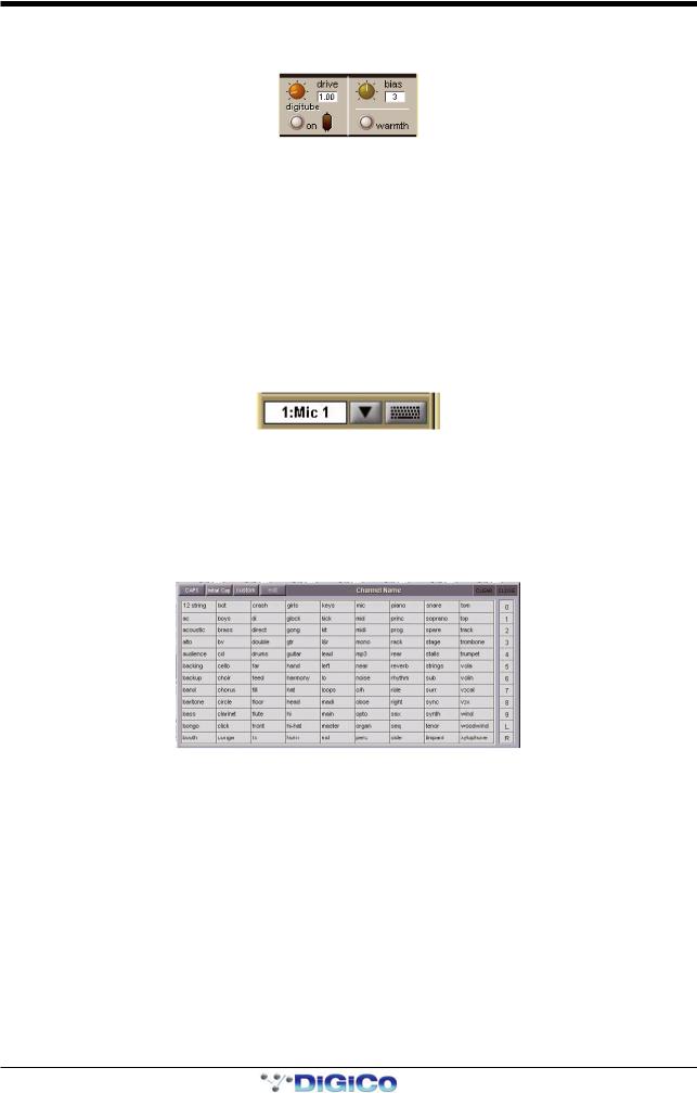
1.2.3 DiGiTube/Warmth .................................................................
The digitube area of the Channel Setup panel allows for the emulation of the non-linearities of a valve amplifier: At low levels the valve is almost linear and at high levels the valve starts to compress and exhibits “soft clipping.”
Click the on button to activate. The number of times the tube can be activated is dependent on which SD console you are using. Please refer to the Console comparison chart in the appendix for more information.
The drive control increases the gain into the valve and automatically reduces the output gain so that the volume stays the same (like gain tracking); the indicator shows how hard you are driving the valve and hence how much distortion is being introduced.
The bias control sets the symmetry of the distortion: At 0 the distortion is symmetrical and produces largely 2nd harmonic (and even) distortions; as the bias is increased, the distortion becomes more and more asymmetrical and starts adding 3rd (and odd) harmonic distortions. In effect, the bias controls the characteristics of the distortion; a lower bias produces a softer distortion, whereas as higher bias produces a harder distortion.
The warmth control (which is hidden if the on button is pressed) switches DIGItube on, sets it to its default settings, and hides the rest of the controls. There is no limit to the number of times warmth can be switched on.
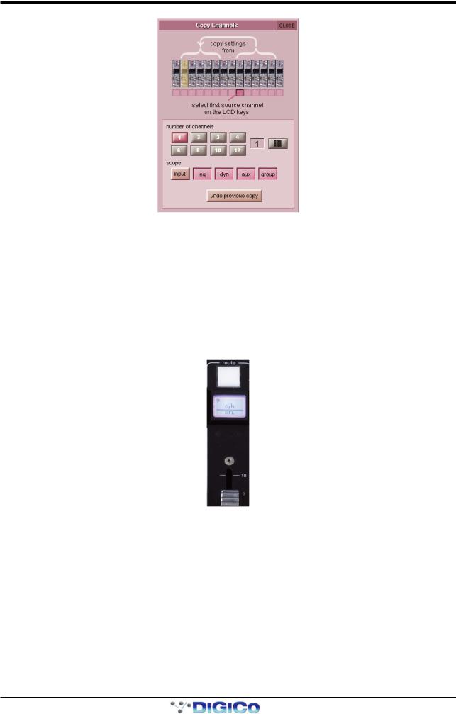
1.2.4 Naming Channels and Busses ............................................
A large number of elements within the console can be custom named. Access to the naming facility is via black and white text boxes with down arrow and keyboard buttons to their right, such as shown here:
To create a name manually, touch the text box or the keyboard symbol to its right to bring up a QWERTY keyboard display. This keyboard includes standard Caps, Shift and Delete functions, as well as Cut, Copy and Paste functions which can be used to move name text between channels. The arrow buttons in the bottom left-hand corner of the keyboard display move the cursor within the text box. Create the new name, either using the on-screen keyboard display or the external keyboard, and press OK. To close the keyboard display without changing the name, press CAN. To move the keyboard display to the following channel, press
Next (or TAB on the external keyboard).
The Channel Name display enables commonly used words to be inserted quickly without the use of the keyboard. This facility is available not only when naming channels but also when naming other elements. To open the Channel Name display, touch the down arrow immediately to the right of the Setup display’s channel name text box.
Touching any word from the display inserts that word into the channel name text box. Further words can then be added to the channel name in the same way, divided by a single space. Numeric and L/R identifiers can be added from the column down the right-hand edge of the display. Text can be entered in CAPS or Initial Caps by pressing the CAPS and Initial Cap buttons in the top of the display. If neither of these are selected, all text is inserted in lower case.
Note that the first text to be inserted from the Channel Name display when it is opened overwrites all previous text.
Note also that text that extends beyond the end of the text box will not be visible!
In addition to the standard word set, a list of user-defined words can be created and inserted by pressing the custom button, located next to the Initial Cap button. The button lightens to indicate that the custom set is displayed.
1-3
Chapter 1 - Channel Types
To add a new word to the custom set, touch the box which you want to use and press edit, located next to the custom button, to bring up a QWERTY keyboard display. Type the required word and press OK. In this keyboard display, the Next button saves any text inserted in the current box and moves the keyboard to the next box in the custom list. To cancel the keyboard display, press CAN within the display, or press edit again. The words in the custom list are inserted into the channel name text box in exactly the same way as words in the standard list. Pressing custom again returns the display to the standard word set.
Tip: As custom names appear in the box in which they are typed, they are not automatically alphabetised. The user may find it helpful to define a system for ordering the custom page.
Note also that the standard word set cannot be edited.
The current name can be cleared by touching the CLEAR button towards the top right-hand corner of the Channel Name display. The Channel Name display can be closed by touching the CLOSE box, in the top right-hand corner.
1.2.5 Channel Safes .......................................................................
The Channel Safes area of the Setup display defines which parts of the channel will be not be affected when snapshots are recalled to this channel.
Note that the above diagram displays the Input channel safes. Output channels display a smaller list of available channel safes.
Select whichever parts of the channel you want to protect in this way by touching the appropriate button. To cancel a safe, press the relevant button again. The buttons turn red to indicate that they are safed. The presence of safes within the channel is also indicated by the label of the appropriate channel part turning red and the background colour of that channel’s name also turning red.
The EQ and dynamics settings can also be safed and unsafed from within the eq and dynamics displays. The whole channel can also be safed and unsafed by pressing the SAFE button at the bottom of on-screen channel (offline software), . It is grey to indicate that some elements of the channel are not safed, and red to indicate that the entire channel is safed.
Channel elements which have been safed are indicated by their text displaying red in the channel strip.
Tip: When some elements of the channel are safed, a double-press on the SAFE button can be used to quickly clear all channel safes (SD5, SD7).
Note: Channel safes refer specifically to snapshot recalls and do not protect channel settings when using the copy from, copy to and presets functions described below.
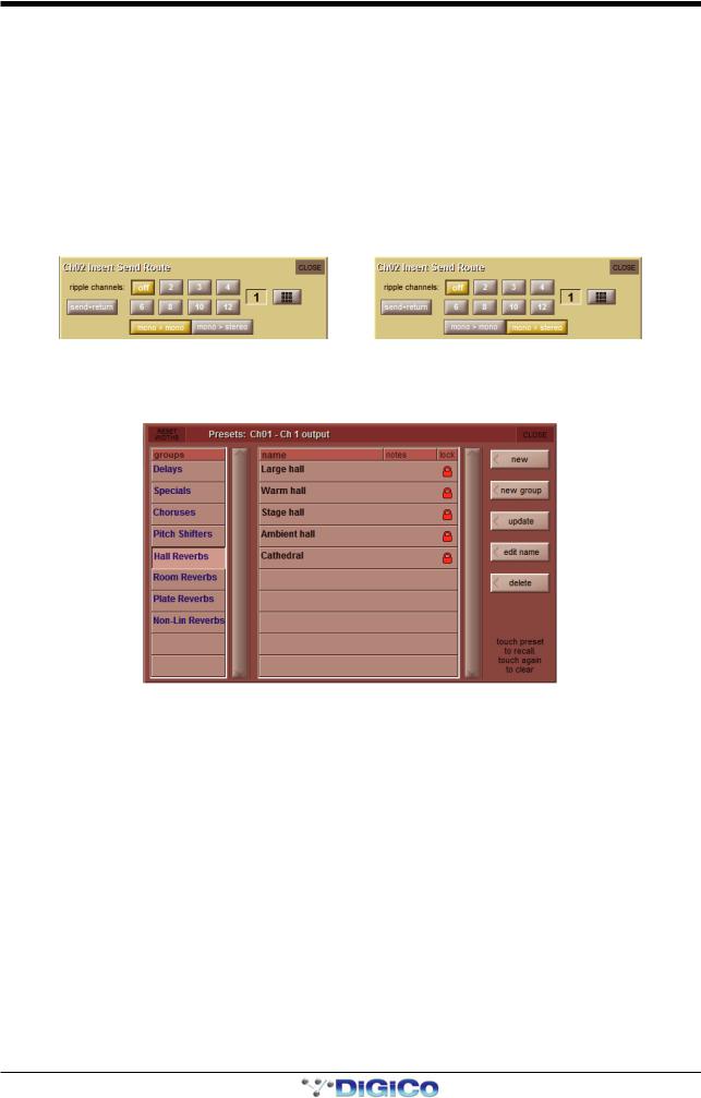
1.2.6 Copy Channels ......................................................................
The Channel Settings area of the Setup display allow channel settings to be copied between channels. The left and right arrow buttons are used to move the Setup display to adjacent channels.
The copy from button allows settings to be copied from other channels to this channel and those to its right: Pressing copy from opens up a Copy Channels display:
1-4
Chapter 1 - Channel Types
The extent of the channel settings to be copied is selected using the scope buttons towards the bottom of the display. Each button lightens to indicate that it is included in the copy function. The number of source channels to be copied is defined either by selecting the appropriate grey numbered button, or by selecting the keypad button to the right of the numbered buttons, typing the required number of source channels into the numeric keypad which appears, and pressing OK. Press the LCD button (shown below) on the left-most source channel in order to action the channel copy. If more than one source channel has been selected, the settings of appropriate number of channels to the right of the source channel will copy to the channels to the right of the destination channel (The current Assigned channel).
For example, to copy the EQ settings on channels 1-8 to channels 9-16 respectively:
-Make channel 9 the Assigned channel and touch copy from
-In the scope area of the Copy Channels display, select only the eq button
-Set the number of channels to be 8.
-Press the LCD/select button on channel 1.
1-5

Chapter 1 - Channel Types
The copy to button allows settings to be copied from this channel to other channels: Pressing copy to opens up a Copy Channels display:
Note that this is a different Copy Channels display from that opened by the copy from button.
The extent of the channel settings to be copied is selected using the scope buttons towards the bottom of the display. Each button lightens to indicate that it is included in the copy function. The number of destination channels to which this channel’s settings will be copied is defined either by selecting the appropriate grey numbered button, or by selecting the button to the right of the numbered buttons, typing the required number of source channels into the numeric keypad which appears, and pressing
OK. Press the LCD button (shown above) on the left-most destination channel in order to action the channel copy. If more than one destination channel has been selected, the settings of the source channel will copy to the appropriate number of channels to the right of the selected destination channel.
For example, to copy the EQ settings on channel 1 to channels 9-16:
-Make channel 1 the Assigned channel and touch copy to
-In the scope area of the Copy Channels display, select only the eq button
-Set the number of channels to be 8.
-Press the LCD/select button on channel 9.
If a copy from or copy to function is actioned by mistake, it can be undone by pressing the undo previous copy button in the current Copy Channels display.
Tip: Use copy to for copying one channel’s settings to a number of other channels; Use copy from to copy the settings of a group of channels to another group of channels.
1.2.7 Channel Presets ....................................................................
Presets are used for storing and recalling settings for channels, fx units, graphic EQs and the matrix. While each preset functions slightly differently, this section provides a basic understanding of how to use the various preset displays:
The left-hand column of a preset display contains the available groups of presets, and touching one of these groups brings up the list of presets within that group in the column to its right (name). The columns to the right of the preset name displays the number of channels whose settings are included in the preset (chs) (Channel and Matrix presets only), the date and time it was created or updated (notes), and whether or not it is locked (lock).
Note that a presets display will only list presets of the relevant type.
1-6

Chapter 1 - Channel Types
To recall a preset, touch the name of the group containing the preset you wish to recall, and then touch the preset’s name. The recall scope buttons at the bottom of the some preset displays allow you to select which elements are recalled and which elements remain unchanged. The buttons are included in the recall when they are lit.
To save the current settings as a new preset, touch the group in which you want the preset to be stored and press the new button. The new preset is automatically named according to the preset type. To alter the preset’s name, type the new name using the keyboard display that appears (or the external keyboard) then, if relevant, touch and edit the number of channels’ settings that you want to store in the preset (the default is one channel). Now touch OK.
Note that pressing CAN in the keyboard display will cancel the display but create the new preset with its default name.
To save the settings as an update of a previous preset, press update, touch the preset you wish to overwrite, and press Yes in the confirmation display which appears.
Note that when updating a previous preset, failing to press update will result in the preset you wish to overwrite being recalled, and the settings to be saved being lost.
To create a new group of presets, press new group. A new group will be created, called group n, where n is the next available preset group number. To alter the group’s name, type the new name using the keyboard display that appears (or the external keyboard) and touch OK.
Note that pressing CAN in the keyboard display will cancel the display but create the new group with its default name.
The edit name button allows preset names and group names to be edited, and the preset to be locked, preventing them from being edited, overwritten, or deleted. The button lightens to indicate that it is active. To edit a preset’s name, make sure the preset is unlocked (see below), activate the edit name button and touch the preset’s name. Type the new name in the keyboard display and press OK. To edit a preset group name, activate the edit name button and touch the group name. Type the new name in the keyboard display and press OK.
To lock the preset, activate the edit name button and touch the preset’s lock column. A grey padlock appears, indicating that the preset is now locked. Touching the lock again with edit name active unlocks the preset.
To delete a preset, press delete, touch the preset to be deleted, and press confirm. To delete a consecutive range of presets, press delete followed by select range, touch the first and last preset to be deleted and press confirm. To delete one preset, or a nonconsecutive range, touch each preset to be deleted and press confirm. To delete an entire group of presets, press delete followed by select all, then press confirm.
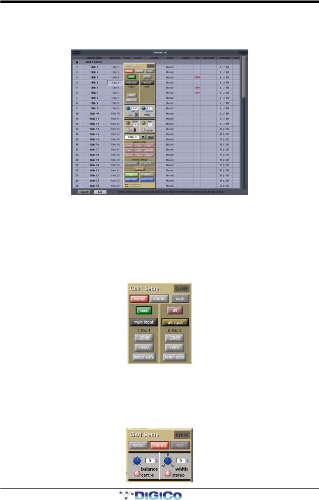
1.2.8 Channel Solos .......................................................................
SD consoles have two solo busses, and each channel can be assigned to solo 1, solo 2 or both solo 1 and 2. If the console was being used for Stage monitors, this would allow, for example, the first solo buss to feed In-Ear monitors and the second solo buss to feed a wedge.
Note: The solo busses are configured in the master solo displays, accessed by pressing the Solos button at the top of the Master Screen.
The channel’s solo routing is assigned in the section at the bottom section of the channel Setup display. Pressing the green solo 1 and solo 2 buttons enables the channel to be routed to solo busses 1 and 2 respectively. The buttons are green to indicate that the solo buss is available, and grey to indicate that it isn’t.
Note that each channel must be enabled for at least one solo buss.
When the blue auto solo buttons are active (indicated by white, rather than grey, text), that channel is automatically routed to that solo buss whenever another channel is soloed to that buss.
Note that a list of channels with auto solo enabled is displayed in the auto solo section of the master solo display. The auto solo function has to be activated by pressing the blue enabled button below the auto solo list in the master solo display. Auto solo is disabled when in single solo mode.
Tip: If you are using effects returns, selecting auto solo can allow soloed tracks to be auditioned with their effects returns.
1-7

Chapter 1 - Channel Types
1.3 Channel Output and Inserts - Common Elements
1.3.1 Channel Strip Output Area ...................................................
The channel strip output area makes up the lower half of the Channel Strip panel (shown below for an input channel). This is where the channel output routes are configured (including Aux outputs in the case of Input channels).
Each channel also has two inserts: insert A and insert B. Both inserts follow the format (mono or stereo) of their channel. The channel strip insert areas are located above the eq section (insert A) and below the 2nd Dynamics section (insert B), and their signals are sent and returned to that position within the signal path: insert A is pre-signal processing (but post filters), and insert B is post signal-processing. Only one point, either insert A or insert B, can be used per channel on SD9 or SD11.
Post-Fade Inserts
Up to 32 mono input channels can have their insert B point switched to a post fader insert point using the button in the Output Setup panel.
Note that Multi channels do not have their own insert controls – each multi-channel component's insert points are configured individually.
Some basic output and insert functions are found in the channel strip. However, most of the output and insert parameters are contained in the channel Output display, accessed by touching the channel’s output or insert areas.
Note that on Input channels, an aux display is opened by touching the aux area. To open the Output display, touch in the muting and naming area below the pan control.
Note that if there are any multi-channel busses in the Session Structure, the pan display will be different from that shown above.
1-8

Chapter 1 - Channel Types
For all output channel types, there is a channel meter displayed in the channel strip. For Input channels, this part of the channel strip contains the aux outputs, as shown above. On stereo and multi-channel format channels, symbols below each meter indicates which component is displayed. LFE channels are indicated by a small box with a dot in it.
Note that input channels can display a meter in the top section of the channel strip. Meter sources are defined in the Options menu, described in the Master Section
Below the meters section of output channels, there is an fx output button. This button brings up either the controller display for the effects preset that has been assigned, or the fx Presets display if no preset has been assigned.
Note that below the aux section of an Input channel, there is a pan control in place of the fx output button. When an effects preset has been assigned to that channel's Direct Out, touching this pan control brings up the FX preset controller display.
Towards the bottom of the channel strip there is a scribble strip text box displaying the channel names.
Note that the channel naming facility is found in both the channel Setup and Outputs displays.
Below the channel name, there is indication of the lowest group (Grp:) output (along with indication of the lowest direct output (Dir:) in the case of Input channels), and indication of any control group (CG:) to which the channel belongs.
The on-screen channel has MUTE and HARD indicators located above the scribble strip. Pressing the worksurface MUTE button
(above the LCD button) silences all outputs from the channel apart from any which have been assigned pre-mute (this option is available for auxes and direct outs). Pressing the worksurface 2nd Function button to activate the HARD mute silences all outputs from the channel, including those which are assigned pre-mute. A dedicated HARD mute button can be found on both SD5 and SD7 worksurfaces.
Immediately below the HARD button, there is a numeric display of the channel’s main fader value in dB. Below the MUTE button there is a CG MUTE Indicator which shows when the channel is muted as the result of its membership of a muted Control Group. At in the bottom left-hand corner of the channel strip, there is a GANG display. To the right of the GANG button there is a
SAFE button. This indicates that one or more of the channel's recall safes have been activated.
1.3.2 Channel Strip Insert Areas ...................................................
Channel strip insert areas include a button for switching that insert send on and off. The button is grey when the send is off, and red when it is on.
Below the on/off button, there is a display of the current insert routing. The send route is displayed on the left, prefixed by S:, and the return route is displayed on the right, prefixed by R:. If no routing has been selected, these areas are blank apart from these prefixes. If the channel is stereo, only the left side of the insert routing is displayed.
1.3.3 Console Output and Insert Routing .....................................
The Output displays for all channel types allow direct routing either to the external IO racks, or to one of a variety of internal locations, for both the channel’s main output (or direct output in the case of Input channels), and its insert send and return.
In addition to touching inside the output area of the channel strip, it is also possible to open each channel'sOutputs display from the Channel Lists display, opened from the Master Screen'sLayout menu: Activate the Edit button at the base of the display, expand the required channel type by touching its entry in the list, then touch the output column within the required channel row.
An outputs display will open within the Master Screen:
1-9
Chapter 1 - Channel Types
Towards the bottom of the Outputs display, there are three buttons marked output (direct in Input channels), insert A and insert B. Selecting one of these buttons assigns that send (or send and return) to the signal routing area above it: When either insert is assigned, the ins A send or ins B send routing button appears in the left-hand column, and the ins A return or ins B return routing button in the right-hand column; When the output (direct output in Input channels) is assigned, the outputs (direct outs in Input channels) routing button appears in the left-hand column and the right-hand column is left blank. Pressing any of these routing buttons opens a routing display.
An extra button labelled send+return is included above the ports list in the Insert Send Route display button. When this button is activated, the send and return routing is linked for all signals within the INTERNAL port: If the Graphic 1 input is assigned to the insert send, the Graphic 1 output is automatically assigned to that insert return. Similarly, if it is the return which is manually assigned, the send automatically copies that send assignment. The send+return button is grey when inactive and brown when active.
The mono > mono and mono > stereo buttons are used when routing a mono channel to internal fx units and Waves plug-ins (where available). When mono > mono is selected, the channel signal is routed to left side of an fx unit, or to a mono Waves rack input. When mono > stereo is selected, the channel is routed to both sides of the fx unit or Waves rack.
1.3.4 FX Presets .............................................................................
Each channel output or insert send can be sent to an internal FX Unit. Pressing the fx presets button at the bottom of the Outputs display brings up the fx Presets display. The fx preset is applied to whichever channel output is active in the Outputs display when the fx presets button is pressed: the main channel output (or direct output), insert send A or insert send B:
Note that column widths can be adjusted by dragging their borders within the title row. To return all columns to their default widths, press RESET WIDTHS, in the top left-hand corner of the window.
For more details of SD FX and FX preset management, please refer to the Master Section Chapter
1.4 Input Channel Specific Functions
1.4.1 Trim and Track ......................................................................
On Input channels which a mic or line input, there is a trim section at the bottom of the channel strip’s input area, consisting of a smaller pot marked trim and a track on/off button. The trim pot digitally trims the level of the input signal, and the level adjustment is displayed to the right of the pot in dB. If track is switched on, the trim level automatically compensates for any adjustments made to the analogue input level: If the analogue input level is increased, the trim level will decrease in order to keep the signal level coming through the channel at the same level. This function is particularly useful when the analogue level is being controlled from another console, such as when this console is running monitor mixes and another console is running Front of House. Control of the trim pot and track on/off button can be assigned to the encoder and button above/below the channel using the assign scrollers to the left of the encoders or the quick select buttons.
Relative Gain-Tracking - Snapshot Recalls Total Gain
“Relative Gain-Tracking” is implemented as a “Snapshot Recalls Total Gain” option at the bottom of the Snapshot Global Scope panel. When a snapshot recalls an input channel trim, it compares the snapshot’s stored analogue gain against the current gain on the channel’s input socket. If there’s a difference it offsets the value recalled by the trim. This only happens when the socket’s rack is in Receive Only, or the analog gain is not in Recall Scope.
1-10
Chapter 1 - Channel Types
1.4.2 Input Routing .........................................................................
Inputs are routed using the channel Setup display, opened by touching in the input area of the channel strip. It is also possible to open the display from the Channel List display, opened from the Master Screen'sLayout menu: Activate the Edit button at the base of the display, expand the required channel type by touching its entry in the list, then touch the output column within the required channel row. A Setup display will open within the Master Screen:
The buttons at the top of the channel Setup display to define the format of the channel: mono or stereo.
Note that Multi-channel formats are configured in a different way from mono and stereo formats, as described later in this chapter
As the channel format affects a number of functions within the Setup display, it is advisable to select the format before any further configuration takes place. The current format of the channel is indicated in the channel strip by the number of meters displayed: One meter for mono channels and two for stereo.
For mono channels, each input channel has two inputs: a main input and an alt(ernative) input. These are selected using the main button in the channel strip. The button is grey when the main input is selected and red when the alt input is selected. The input can also be selected using the main and alt buttons towards the top of the Setup display. These buttons light to indicate which one is currently selected. For stereo channels, the alternative input becomes the right side of the stereo input, and therefore no main and alt input selection buttons are shown.
The inputs available on an Input channel include feeds from the external IO racks, the local inputs on the back of the console and a variety of internal signals. Pressing either the main input or alt input routing button in the Setup display opens the Input Route display. The signal feeding each input can then be selected as described in the Getting Started section of this manual.
1.4.3 Input Configuration ...............................................................
If a channel is stereo, balance and width controls appear below the mono and stereo buttons: The left-hand blue pot controls the balance and can be reset to centre by pressing the centre button below it. The right-hand blue pot effects the width of the stereo signal, with a range from mono to wide. The width can be reset to stereo be pressing the stereo button beneath the width pot. The value of the balance and width is displayed to the right of each pot as a percentage divergence.
1-11

Chapter 1 - Channel Types
Stereo channels also have an m-s button, located above the input routing button, which switches in a decode function for replaying M-S signals as a normal stereo pair. There are three further buttons in this panel: L<>R swaps the channel’s left and right outputs, L>L+R sends the left signal to both left and right busses, and R>L+R sends the right signal to both left and right busses.
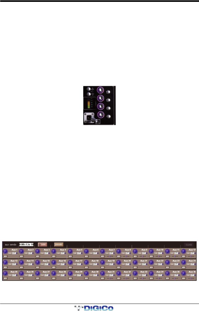
1.4.4 Channel Metering .................................................................
Channel meters can be displayed in the top section of the Input channel strip, in place of the input and filters areas. To do this, press the meter (SD7, SD5), rotary assign (SD8, SD10), screen scroll (SD9, SD11) up button, located on the console worksurface. If these encoders are initially assigned to the trim function, you will need to press the rotary assign up button twice to display the meters.
If you adjust any parameter which is hidden by the meters, the meters will be hidden momentarily, allowing adjustments to be viewed.
1.4.5 Output Routing .....................................................................
Signals can be fed from Input channels to four different places: aux busses, group busses, insert sends and direct outputs. Insert routing and basic direct output routing are described in the Getting Started Manual.
The top half of the output section of the Input channel strip contains the aux buss controls, as previous described. Below the auxes, there is a pan control, affecting the relative levels of the channel’s left and right outputs to any stereo routing destinations. The controls are formatted to match the format of the buss with the most components:
-Where there are only stereo or LCR busses, a simple pan slider is shown (see below left). Move the slider to adjust the pan. A text box indicates the panning position as a percentage from the centre towards the right.
-Where there are LCRS busses, a two-dimensional panning scope is shown (see below centre). Move the central grey square to adjust the position. Text boxes indicate the left-right and front-back position.
-Where there are 5.1 busses, a two-dimensional panning scope is shown, along with a pink LFE level control (see below right). Move the central grey square to adjust the position. Text boxes indicate the left-right and front-back position, as well as the LFE gain.
There is also an LR/LCR Blend control. This control allows adjustment of the amount of signal that is sent to the centre leg (where one exists) of a surround buss. In the extreme left LR position, no signal will go to the centre leg:
The pan of the Assigned channel can be controlled using the worksurface joystick (SD5,7,8,10). The pan control can also be assigned to one of the encoder rows. LR/LCR Blend is adjusted using the 2nd function button.
1-12
Chapter 1 - Channel Types
1.4.6 Aux Busses and Assignable Controls ..................................
Within an Input channel strip, each aux send has a level trim and on/off switch to the right. The switch is grey to indicate that the send is off, and red to indicate that it is on. The trim level is displayed in dB on the right of the channel strip, underneath the aux number.
There are three places within the channel from which the aux sends can be fed, as indicated by the source display immediately to the right of the level trim:
PRE Pre-fader
POST Post-fader
Pre-M Pre-mute (and pre-fader)
The source position can be changed by pressing the worksurface 2nd function button and using the switches below the aux send encoders. The source for each aux can also be adjusted globally via the aux channel’s Setup display.
On stereo aux sends, there is a pan control to the right of the on/off switch. This can be adjusted by pressing the worksurface
2nd function button and using the rows of encoders below the worksurface screen. The pan controls for each aux can be globally linked to the channel fader via the aux channel’s Setup display.
At the bottom of the assigned channel SD7 worksurface controls, there are four dedicated aux encoders with buttons, which control four contiguous aux send pots and on/off switches for the Assigned channel:
The auxes controlled by these encoders and buttons can be selected using the scroll buttons to the left of the top encoder, and is indicated by purple ring on the on-screen aux sends.
Note that this assignment is channel specific and will be recalled if the Assigned channel is changed and returned to that channel.
The encoders and buttons immediately below the Channel Strip can be used to control either the aux sends, or a separate function. This function is referred to as the ‘locked’ function, as it does not change when the auxes are moved. The button at the end of each row, next to the LCD display, flips the assignment of that row between the aux sends and the locked function. Touching any on-screen aux send assigns the highest available encoder row to that send, and assigns any other available encoder rows to the aux sends below it. The scroll button outside the bottom left-hand corner of the screen can also be used to change which auxes are assigned to the encoders. (SD5,7,8,10)
Note that only six auxes can be displayed in the Channel Strip panel at once. The panel will always display the auxes assigned to the encoder rows below it. This means that the auxes controlled by the dedicated aux encoders in the channel worksurface controls may not be visible.
By default, the encoders control the aux level and the button controls the aux on/off status. However, by pressing the 2nd function button (located on the surface), the button becomes the aux’s source selector (toggling between PRE, POST or Pre-M), and the encoder becomes the pan control of a stereo channel. On mono auxes, the encoder has no second function.
It is also possible to show all of the aux sends for a channel in a single display and assign them to the rotaries beneath the screen. This is done by assigning the required channel to the aux controls (the assigned auxes will be displayed in dark purple with a dark purple surround) then touching one of the assigned auxes. The layout of the display indicates which encoder each aux is assigned to; if there are more sends than rotaries, the assignments becomes scrollable using the Screen Scroll function. The Picture below shows an SD7 with 36 Sends.
Once you have adjusted the auxes in this display, you need to close it manually before opening any other channel detail display.
Note that further worksurface assignments of auxes is available via the Surface, Faders and Solo tabs of the Options menu.
1-13
Chapter 1 - Channel Types
1.4.7 Group Outputs .......................................................................
Group outputs are routed from within the groups section of the channel Outputs display. Touching the mono button to the left of the display produces a list of available mono groups in the right of the display, and touching the stereo or surround format buttons produces a list of the other types of group. These buttons 'light' to indicate that it is their group outputs list whicis currently displayed, and 'half-light' to indicate that there is routing to busses of that format which isn't shown in the display. Touching any of the groups within each list routes the channel to that group. Each channel can be routed to as many mono and stereo groups as have been created.
Unlit: mono routing inactive and not shown
Lit: stereo groups shown to right
Half lit: 5.1 routing active but hidden
Any mono groups being fed by a stereo channel will receive a L+R summed signal of the channel output.
The lowest selected group output is displayed in the channel strip, below the left side of the channel name, and the currently selected direct output is displayed below the right side of the channel name.
When a new session is created, the lowest numbered stereo group is always designated the Master. Therefore, all input channels are routed to it by default, and the master fader(s) are assigned to it.
1.4.8 Direct Outputs .......................................................................
Basic routing is described in your console's Getting Started section. Once the direct output has been routed, it is switched onby pressing the grey on button next to the output level meter in the grey area below the direct outs routing button. The direct out is taken post-fader by default, but can be switched to pre-fader or pre mute by pressing the button to the right of the on button. The current selection is displayed to the right of the button.
1.5 Output Channels Specific Functions
1.5.1 Unfolding Channels ..............................................................
Group and Aux Channels which are stereo or surround have an Unfold button above their meters, which is used to display the components of the signal in their own channel strip with a master channel displayed to their left.
In the top section of the unfolded Master channel, buttons for each component channel allow you to define which channel's elements are displayed in the Folded View.
In the middle area of the unfolded Master channel, the links between component channels can be edited. Links function in the same way as Gangs, but are limited to the components of a multi-channel signals. To edit links, press the Set Links button so that it goes red, then press the LINK buttons above the channel meters in the channels to be linked or unlinked - each button will take on the same colour, indicating that they are linked. To remove a link, press the LINK button while Set Links is active. Note that if you start a set of links and then de-link and re-link another channel, a new link set will be started, as indicated by the introduction of a new link colour. When you have finished linking channels, deselect Set Links. You can also clear all links and link all using the buttons below Set Links.
Note that if component channels have different settings when linked, changes in hidden, linked channels will be made relative to the change in the Folded View channel, but the display will only reflect the Folded View channel.
Below the link buttons in the master, there are buttons for each element in the components' channels -trim & delay, filters & eq, dynamics and faders & mutes. Pressing one of these buttons will cause that element in all the channels to match those of the Folded channel.
Once you have finished with the unfolded view, press the FOLD button to fold the channels back together. The picture below shows a 5.1 Buss from an SD5/SD7
1-14

Chapter 1 - Channel Types
Folded View
Channel
Unfold Links
Settings
Fold
1.5.2 Group Channels Specific Functions ....................................
The Group channel input signals are defined within the Input channels Output display. The top section of the Group channel Setup display lists all of the currently selected inputs to that group. The inputs list can be scrolled using the scroll bar to the right if necessary. Below the list there are two buttons: clear all removes all of the input routes to that group. Pressing this button produces a confirmation box in which the clear all can be confirmed or cancelled. connect all routes all Input channels to the group.
Note: With either the connect or clear all functions, you can exclude individual channels from the function by touching their faders when the button is pressed.
Group channel output routing functions are very much like Input channel output routing.
1-15
Chapter 1 - Channel Types
Aux Sends on Groups
Group output Busses can send audio to Aux output busses. Pressing the Aux send button, located above the output meter, will open the expanded aux panel and the sends will be assigned to the under screen rotaries.
To access the aux sends for a stereo, LCR, LCRS or 5.1 Group, the Buss must be unfolded to show the individual legs, each leg having it’s own aux send levels.
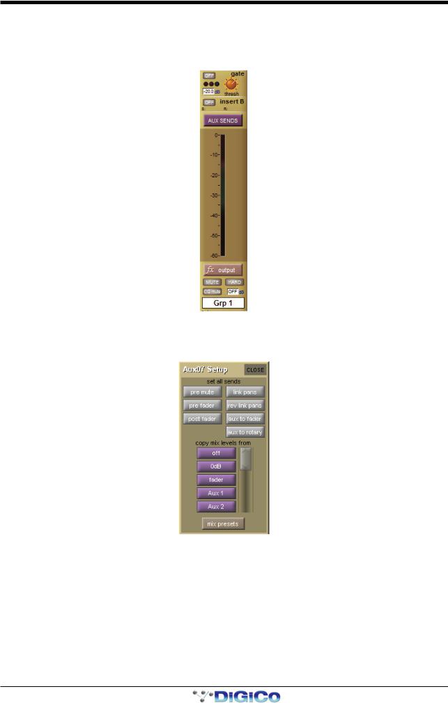
1.5.3 Aux Channels Specific Functions ........................................
As the Aux channel input signals are defined within the Input channels, there is no input selection available within the Aux channel
Setup display. There are, however, a number of configuration options in the top half of the Setup display:
The set all sends buttons at the top of the Setup display affect the sends to that aux bus from all of the Input channels.
The three buttons on the left, pre mute, pre fader and post fader, set the point in the channel from which the aux send is taken. The current send point is displayed next to the aux send level in the Input channels.
Note that send points can also be individually selected within the Input channel using the 2nd function button.
Pressing the link pans button, located to the right of the pre mute button, links that aux send pan to the main channel pan in the
Input channels. This button lights red to indicate that it is active. Further indication is provided by the aux pan slider in the Input channel strip being lit pink. Rev link pans inverts the link between the channel pan and aux send pan.
Pressing aux to fader assigns control of all input channel’s auxiliary sends to the channel faders.
1-16
Chapter 1 - Channel Types
Pressing aux to rotary assigns control of all input channel’s auxiliary sends to the top available encoder row beneath the Channel Strip panel.
The purple copy levels from buttons also affect the sends to that aux bus from all of the Input channels. The buttons list can be scrolled using the scroll bar on the right. These buttons are used for universally setting the aux send levels:
Off sets the level to off and 0dB to 0db. fader sets each Input channel’s aux send level to match the level of its channel fader.
The remaining copy levels from buttons copy a different set of Input channel aux send levels to that aux send.
Note that when a copy levels from button has been pressed, send levels can still be individually readjusted within the Input channel.
Touching the mix presets button (below the copy mix levels from list) opens the Aux Mix Presets display, where you can store and recall presets of an aux send's parameters for all input channels, using the standard presets procedure, detailed in
Section 2.
1.5.4 Matrix Channels Specific Functions ....................................
As the Matrix channel input signals are defined within the Matrix inputs display, there is no input selection available within the Matrix channel.
1.6 Channel Signal Processing
Each channel type contains similar signal processing functions, including EQ and dynamics. Input channels also have high-pass and low-pass filters. Pressing on each of these areas of the channel strip will open the relevant signal-processing display.
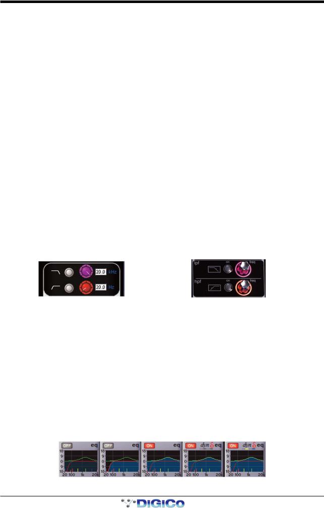
1.6.1 Channel Filters ......................................................................
(All SD input channels and on SD8,9,11 output channels)
The filters section of the channel-strip is located below the input section of each input channel. It consists of two frequency pots, each with its own on/off button and a display of the filter’s cutoff frequency (the -3dB value) in Hertz. The on/off buttons are grey to indicate that the frequency band is off, and red to indicate that it is on. The low-pass filter is at the top and the high-pass filter is at the bottom, and both have a roll-off of 24dB per octave. The filters directly follow the input section in the signal chain.
The filters area is replicated at the top of the EQ/filters display, accessed by touching the EQ area of the channel strip. The filter can be configured using the dedicated filter encoders and buttons at the top of the channel worksurface controls:
A graphic representation of the filters is included in the EQ graph located below Insert A in the channel strip, described below.
The red line in the graph represents the current filter settings.
Note that the filters section of the input channel strip may be hidden behind channel meters. In this case, moving the filter encoders will cause them to be displayed momentarily. To hide the meters and retain a permanent display of the filter controls, press the assign down button, located to the left of the encoders above the screen.
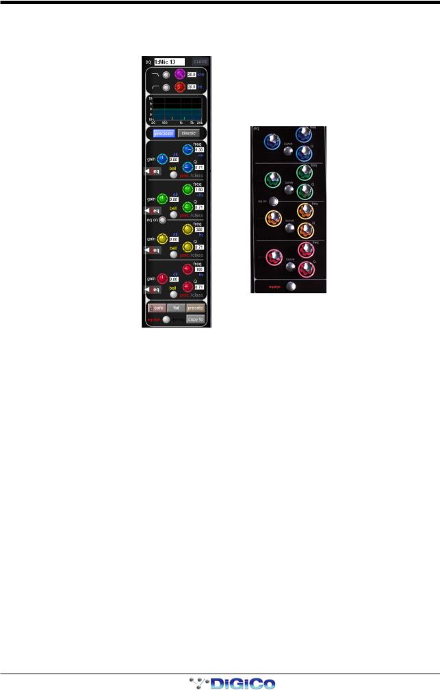
1.6.2 Input Channel EQ ..................................................................
The SD input channel EQ has four bands, each of which can be made dynamic. The four EQ bands are colour coded: Blue for HF, green for HMF, yellow for LMF and red for LF. The in-channel display is located below Insert A and consists of a graphic representation of the current EQ and an on/off button. The button is grey to indicate that the EQ is off, and red to indicate that it is on. The green line in the graph represents the frequency response of the EQ, and the red line represents the response of the filters – each line goes bright to indicate that it is on. The extent and brightness of the clouded area in the bottom half of the graph also indicates which elements are on. The central frequency of each band is displayed by small lines in the band colours, along the bottom of the graph.
EQ and filters |
EQ off, |
EQ on, |
Dynamic EQ on |
Dynamic EQ on |
both off |
filters on |
Filters off |
bands 2+4, with |
band 2+4, with |
|
|
|
both bands off |
both bands on |
1-17
Chapter 1 - Channel Types
Touching the EQ area of the channel strip brings up the EQ/filters display. The EQ section of the display is below the filters section, and has another graphic representation of the current EQ at the top. Touching this EQ graph will open an expanded view of the graph. The EQ can be configured using the dedicated encoders and buttons on the worksurface which follow the same layout as the display:
In both the EQ/filters display and on the worksurface, each band has a ± 18dB gain controller on the left, a frequency controller (ranging from 20Hz to 20kHz) top right and a Q control bottom right. Each pot has its value displayed to its right.
Bands can be switched between a bell curve (which is the default setting) and a Hi/lowshelf using the bell button.
On SD5/SD7, the bell button's2nd function allows the each band to be switched between prec (precision, where the Q is narrower on the cut curve than the boost curve) and class (classic, where the cut and boost Q curves are identical in width).
The active setting is shown in red to the right of the bell button. Pressing the precision or classic buttons above the EQ controls will switch all four visible bands to that shape. The active button goes blue – if different bands are employing different shapes, neither button will be lit.
The EQ is switched on using the eq on button between the HMF and LMF controls which rings red to indicate that it is on.
Note that when a band is in dynamic mode, it can also be switched on and off individually in the dynamic display. See below.
Towards the bottom of the EQ/filters display are four grey buttons marked safe, flat, preset and copy to. Touching safe adds the EQ to that channel’s list of channel safes. Touching flat resets the EQ gain controls to 0dB. Touching preset brings up the
Presets display which can be used to save and recall presets. Touching copy to will open the copy to panel with the EQ section Pre Selected.
Below these buttons is a smaller round button which is also found at the bottom of the channel worksurface controls, for switching the signal-processing order. The default setting is EQ followed by dynamics, as indicated by the eq-dyn label being to the left of the button. Pressing this button reverses the order, as indicated by the labelling switching to an dyn-eq display to the right of the button.
1-18

Chapter 1 - Channel Types
Dynamic EQ
In a dynamic EQ module, the EQ adjustment is applied dynamically, based on the level of the incoming frequency relative to a predetermined threshold. Dynamic EQ is accessed by touching the red "Delta" symbol on any EQ band. Activate the dynamic function by pressing the dynamic on button (a red ring will appear in the button). When dynamic EQ is active, you can also mute and unmute the entire EQ band by pressing the band on button (a red ring indicates that the band is unmuted).
When any dynamic EQ bands are on, a dynamic EQ icon appears above the EQ graph in the channel strip (as shown on the previous page). The four boxes beneath the icon indicate the status of each band – each box is empty (light grey) when the band dynamics are off, dark grey when the dynamics are on but the band is off, and coloured when the dynamics and band are on.
DiGiCo dynamic EQ can operate in two modes: 'over' or 'under':
Over Mode
To place the dynamic module into Over mode, ensure that the Over indication below the threshold control is not illuminated.
When the signal entering the module passes the threshold, the EQ adjustment (as determined by the frequency and Q controls) starts to be applied, up to a maximum adjustment, determined by the EQ band gain control. The manner in which the EQ adjustment is applied once the threshold has been reached is determined by the attack, release and ratio controls.
Gain : |
Sets the maximum EQ adjustment that could be applied |
Frequency / Q / Curve : |
Adjusts the EQ characteristics |
Threshold : |
Sets the threshold at which the EQ starts to be applied |
Attack : |
controls how quickly the dynamic module responds to level passing the threshold |
Release : |
adjusts how quickly the module responds to a fall in level |
Ratio : |
controls how quickly the maximum adjustment is reached once the threshold level is passed. |
Over Mode is generally used with a reduction in gain at a specific frequency, such that when the threshold is reached, a gradual reduction of level at that frequency is applied. This could be used to control a change in tonal characteristics as a singer pushes their voice to sing louder.
Under Mode
To place the dynamic module into Under mode, ensure that the Over indication below the threshold control is illuminated.
In under mode, the maximum EQ adjustment (as determined by the frequency, Q and band gain controls) is applied when the signal entering the module is below the threshold. As the signal level approaches the threshold, the EQ adjustment is reduced to the point where there is no EQ being applied at the threshold. The manner in which the EQ adjustment is reduced as the signal level approaches the threshold is determined by the attack, release and ratio controls.
1-19
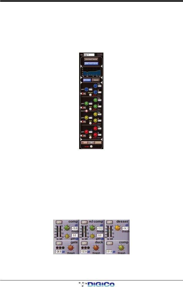
Chapter 1 - Channel Types
1.6.3 Output Channel EQ ...............................................................
The EQ located in each output Channel is similar in operation to the input channel EQ, with the following exceptions:
Output channel EQs have either have 4 Bands of EQ and HPF/LPF (SD8,9,11) or eight bands – four pre-insert and four postinsert (SD5,7,10). Buttons in the channel strip (pre-insert eq and post-insert eq) and in the EQ display (pre-insert bands and post-insert bands) select which set of bands is assigned to the worksurface and display controls. All eight bands are shown in the EQ graph, with the pre-insert bands shown in lighter shades than the post-insert bands.
The precision and classic buttons above the EQ bands only affect the four bands currently displayed, and not the full 8 bands available. The pre-insert bands do not have dynamic EQ or bell-shelf switching – the bell button is only used for switching between precision and classic Q shapes. (SD5,7,10)
1.6.4 Channel Dynamics ................................................................
The SD channel dynamics includes two dynamics modules. Module 1 is a fully configurable compressor which can be split into three frequency bands or configured as a de-esser; Module 2 can function as a gate, a ducker, or a compressor, all with highand low-pass filtering on the key input.
The in-channel display is located below the eq display, with Module 2's controls shown below Module 1's. Each module can be switched on by pressing the on/off switch in the upper left corner of its channel area. These buttons are grey when off and red when on.
The display includes an input (In) meter and a gain reduction (GR) meter. The input meter has arrows to its right which display the current threshold values for each module. Each arrow is distinguished by its colour, which matches its associated threshold pot.
When Module 1 is in Compressor or Multiband mode, threshold and gain pots, each with a value display in dB, are also shown in the channel strip (when in Multiband mode, the threshold pot affects all bands and the mid band's value is displayed). The Deesser only displays a threshold pot and its value. There is a threshold pot (with value display) shown for Module 2, with three status indication lights shown when in Gate or Ducker mode.
1: Compressor |
1: Multiband |
1: |
De-esser |
2: Gate |
2: Ducker |
2: |
Compressor |
Pressing anywhere in either module area brings up the expanded dynamics display.
To switch each module between its three modes, touch the button on the left of its expanded display, marked comp/multi/ desser for Module 1, and gate/duck/comp for Module 2. Both modules can be switched on using the on button below their
1-20
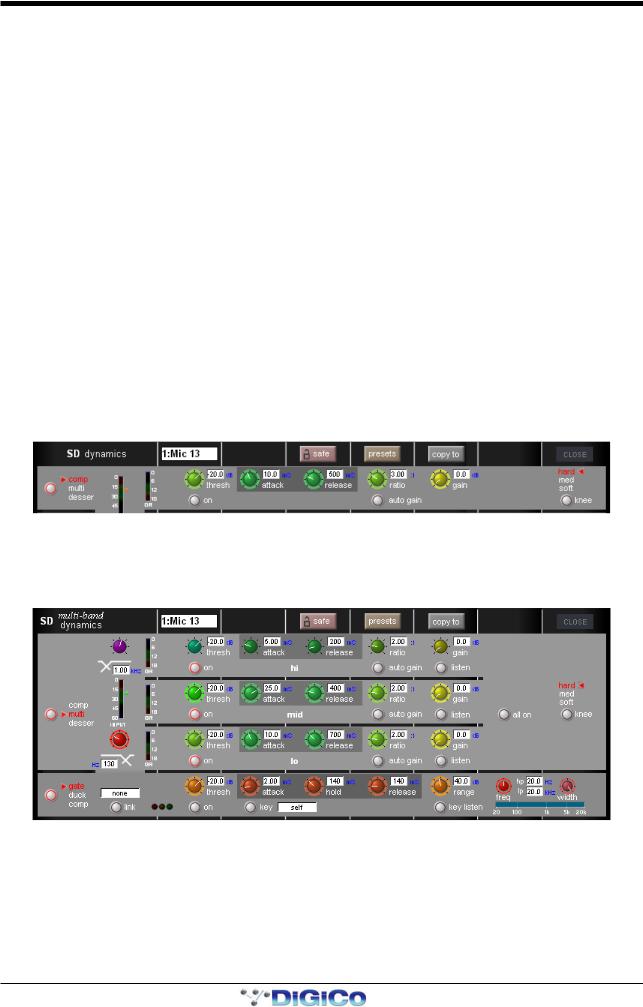
Chapter 1 - Channel Types
threshold buttons. The joint input meter is shown in the expanded display, with the same threshold indication. In multiband channels, each component has its own meter.
The pots within the expanded display are automatically assigned to the worksurface encoders below the screen when the dynamics panel is expanded, as indicated by the matching coloured rings around the pots and encoders. When in Multiband mode, each band is assigned to a row of encoders. When Module 2 is also on, it appears in the bottom row of encoders.
Note that if the gate occupies the bottom row of encoders while the multiband compressor is on, the HF compressor band is not displayed, and the MF and LF bands both shift up a row.
At the top of the expanded display are buttons marked safe, presets and copy to. Touching safe adds the dynamics to that channel’s list of channel safes. Touching preset brings up the Presets display which can be used to save and recall presets. Touching copy to will open the copy to panel with the dynamics section pre selected.
If a link button is shown below the input meter, it allows two channels to be linked together. In other words, the other channel's signal is added to this compressor’s control circuit input, and this channel’s signal is added to the other channel’s control input. On stereo input channels, the link is always active and the button isn't shown. On stereo output channels, thelink button is available and the link is always between left and right components; it is active by default.
On mono or multiband channels, pressing this button brings up a dynamics link display listing Channels, Groups and Auxes signal groups in the left-hand side. When one of these signal groups is selected, their available signals are listed in the righthand side of the display. Select a signal to link to and close the display.
The link button is ringed red and the linked channel’s number and name is displayed in the box above it to indicate that there is a link present. To cancel the link, press the button again and deselect the link signal.
Note that when a link channel has no name, the display repeats the channel number.
Beyond the link function, the different modes of each module have completely separate settings: No settings are copied between them. If you switch from one mode to the other, the settings will be reset to there defaults. The controls specific to each mode of each module are described below:
Module 1: Compressor
In Module 1's compressor,threshold, attack, release, ratio and gain controls are provided, each of which function in the normal way. The compressor has an auto gain function which is switched on by pressing the auto gain button below the ratio pot. This function automatically adjusts the gain makeup when changes are made to the threshold, thus keeping the compressor output steady. The threshold knee can be switched between hard, mid and soft using the knee button in the right side of the module. The gain reduction (GR) meter is duplicated in this display.
Module 1: Multiband Compressor
In Module 1's multiband compressor, each band includes all of the parameters found in the single band compressor. The link function remains available for the whole compressor, and is not assigned to any band. The bands can be switched on individually using the on buttons in the left-hand side of each band, or together using the all on button in the display’s right.
The crossover frequency between bands is controlled using the purple and red pots to the left of the hi and lo bands. Each crossover has a range of 20Hz to 20kHz, and the crossover frequencies are displayed below each pot. Each band can be auditioned by pressing the listen button below each gain pot.
Important Note: In software versions earlier than V463, when any band is switched off, that band will not pass audio. In later software versions, bands which are off are bypassed rather than muted.
1-21

Chapter 1 - Channel Types
Module 1: De-esser
The de-esser's controls are similar to those of the compressor, with the following exceptions: In the right side of the module,there is a band-pass filter control for the de-esser sidechain, with pots provided for the centre frequency and filter width. The -3dB points for the hi-pass (hp) and lo-pass (lp) frequencies are shown. The filtered sidechain can be auditioned by pressing the listen button. Note that there is no makeup gain included.
Module 2: Gate
Gates can be keyed by a different signal by pressing the key button below the attack pot. This brings up a Gate Key Route display from which a key input can be selected. Consecutive channel gates can be keyed by consecutive input signals using the ripple channels function. The key button is ringed red and displays the key input in the text box to its right to indicate that another signal is keying the gate. The key input signal can be auditioned by pressing the key listen button underneath the range pot.
There is a band-pass filter available: the width control adjusts the width of the band being passed, and the freq control moves that band through the frequency range. The hiand lo-pass sidechain filter frequencies are displayed.
To the right of the link button, there are red, amber and green status indication 'traffic lights'.
Module 2: Ducker
The ducker has exactly the same controls as the gate, though the sidechain performs the opposite function of ducking the signal rather than gating it.
Module 2: Compressor
Module 2's compressor is identical to the single band mode of Module 1, with the addition of the band-pass filter described above, and a sidechain input function (S/C) which functions exactly like the key function of the gate.
1.7 LCD Functions
1.7.1 Introduction to LCD Functions .............................................
The LCD button/display is located above the channel fader, and is included in every channel in both the centre section and side sections of the consoles. The channel number is displayed in the top half and the current function mode of the button is displayed in the bottom half of the display and is also indicated by its colour.
LCD buttons (SD5,7) or Select Buttons (SD8,9,10,11) are able to fulfil a number of different functions, and are even involved in selecting their own function. These functions are accessed by pressing the lcd function button, located above the bank buttons on each section of the desk. When this button is pressed, LCD displays for the channels associated with it turn yellow, indicating that they have become function mode selectors:
1-22
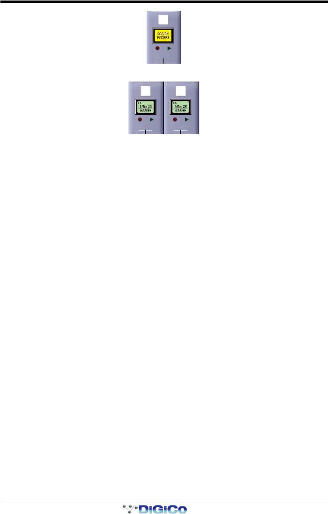
Chapter 1 - Channel Types
Selecting one of these options assigns that function mode to the LCD/select buttons for all the channels within the banks associated with that lcd function button.
There are twelve different function mode options.
1.7.2 Solo ........................................................................................
When an lcd function button is pressed, the left-hand LCD display is labelled SOLO. When SOLO mode is selected, the LCD/ select buttons become solo buttons. The bottom half of the LCD display indicates which solo busses are available to the channel, as defined in the channel Setup display and the SOLO CHOICE function mode (described below). The display also shows whether each buss is AFL or PFL, as defined in the top-left corner of the master solo display.
In SOLO mode, the LCD displays are coloured according to their channel type when not soloed, and coloured green when soloed.
Note that this is the default mode of the LCD/select buttons, current when no other function modes have been selected.
1.7.3 Solo Choice ...........................................................................
When an lcd function button is pressed, the second LCD display from the left is labelled SOLO CHOICE. When this mode is selected, the LCD/select buttons are used to select the solo bus assignment for that channel, toggling between 1, 2 and 1+2.
In SOLO CHOICE mode, the LCD displays are coloured cyan.
1.7.4 GANG .....................................................................................
When an lcd function button is pressed, the third LCD display from the left is labelled GANG. When this mode is selected, the
LCD/select buttons are used for linking together all channel controls. All LCD/select buttons which are then pressed will have their controls linked. In the case of currently ganged channels, the LCD/select button can be used to remove them from their ganging group. The colour of the GANG symbols in the bottom left-hand corner of the on-screen channel display indicate what ganging groups exist: All faders which are ganged together will share one colour. Each time the GANG lcd function is selected, a new ganging group is started, as indicated by the GANG symbols turning a different colour.
To gang channels across different surfaces of the console, activate the GANG LCD function on each surface before starting to build the gang. A single cross-surface gang can then be created using the LCD/select buttons in the usual way.
To stop adding channels to the current gang and start a new gang, simply reselect the GANG LCD function.
When channels are ganged together, operating any of their channel controls will cause all other channels within the ganging group to replicate that movement. Pan and phase controls are not included in gangs.
Note that it is the level change associated with the fader movement which is replicated, not the physical distance the fader is moved.
Note also that when a ganged channel is muted, those channels within the ganging group which were already muted will stay muted. When the channel is then unmuted, all channels unmute, irrespective of whether they had been initially muted.
Note also that when any member of a gang is Assigned, the Undo function will always take the faders back to their position when the channel Assignment was made.
Channels can be temporarily isolated from Gangs by pressing the Option button.
Note that gangs cannot be edited once they have been created.
1-23
Loading...