


S31
Table of contents
 Loading...
DiGiCo S31
DiGiCo S31 User Guide
Version A for Software Version 1.3
DiGiCo S31

DiGiCo S31
Copyright © 2016 Digico UK Ltd
All rights reserved.
No part of this publication may be reproduced, transmitted, transcribed, stored in a retrieval system, or translated into any language in
any form by any means without the written permission of Digico UK Ltd. Information in this manual is subject to change without notice,
and does not represent a commitment on the part of the vendor. Digico UK Ltd shall not be liable for any loss or damage whatsoever
arising from the use of information or any error contained in this manual.
Software License Notice
Your license agreement with Digico UK Ltd, which is included with the S31 console product, species the permitted and prohibited uses
of the product. Any unauthorised duplication or use of Digico UK Ltd software, in whole or in part, in print or in any other storage and
retrieval system is prohibited.
Licenses and Trademarks
The S31 logo and S31 name are trademarks. Digico UK Ltd and the Digico UK Ltd logo are registered trademarks of Digico UK Ltd.
Digico (UK) Ltd
Unit 10
Silverglade Business Park
Leatherhead Road
Chessington
Surrey
KT9 2QL
England
Telephone: +44 (0)1372 845600
Fax: +44 (0)1372 845656
Email: sales@digiconsoles.com
WWW: http://www.digico.biz
Manual Issue and Date: Issue A - August 2016 - For Version 1.3
Software Licence Agreement
"Product": S-Series software product produced by Digico UK Ltd intended for use on Target Platform identied below.
"Target Platform": Digico S-Series Digital Console systems.
In return for the payment of the one-time fee, the Customer (identied at the end of this Agreement) receives from Digico UK Ltd a
licence to use the Product subject to the following terms and conditions.
1. The Product may be used without time limit by the Customer on the Target Platform.
2. The Customer must register the Product with Digico UK Ltd. Registering the Product is deemed an acceptance of the terms and
conditions in this agreement.
3. The Product and its licence are not transferable, and the Customer is not permitted to onward-license to any third party. The Cus-
tomer indemnies Digico UK Ltd against any and all claims and actions arising from third party use of copies of the Product made by
the Customer.
4. The Customer agrees not to attempt to decompile the object code of the Product otherwise than in circumstances specically provided for by law, and then only after consultation with Digico UK Ltd.
5. The Customer agrees not to use, or licence the Product for use, with equipment other than the Target Platform.
6. The Customer agrees not to modify the Product without the prior written consent of Digico UK Ltd.
7. This Agreement applies to any enhancement or upgrades that may become available for the Product.
8. This Agreement does not transfer any right, title, or interest in the Product to Customer except as specically set forth herein.
9. Digico UK Ltd reserves the right to terminate this Agreement upon breach, in which event Customer shall thereafter only be authorised to use the Product to the extent that its contractual commitments to third parties require and then only where such commitments relate to use of the Product as authorised in the foregoing provisions of the Agreement.
LIMITED WARRANTY - Digico UK Ltd warrants for a period of 1 year from the date of purchase of the Product, the Product will reasonably execute its programming instructions when properly installed on the Target Platform. In the event that this Product fails to execute
its programming instructions during the warranty period, the Customer's remedy shall be to return the Product to Digico UK Ltd for
replacement or repair at Digico UK Ltd option. Digico UK Ltd makes no other express warranty, whether written or oral with respect of
this Product.
LIMITATION OF LIABILITY - Except as otherwise expressly provided by law, (a) the remedies provided above are the Customer's sole
and exclusive remedies and (b) Digico UK Ltd shall not be liable for any direct, indirect, special, incidental, or consequential damages
(including lost prot whether based on warranty, contract, tort, or any other legal theory.)
This agreement is made under the Laws of England.
LICENCE NO: ...................................................................................
REGISTRATION DATE: ....................................................................

DiGiCo S31
Contents
1.1 The Console .......................................................................................1-1
1.2 Before You Start ................................................................................1-2
1.2.1 Worksurface Layout .............................................................1-2
1.2.2 Layers and Banks .......................................................... .......1-3
1.2.3 Using the Control Surface ...................................................1-3
1.2.4 The Selected Channel ..........................................................1-4
1.2.5 The Under Screen Controls .......................................... .......1-4
1.3 The Expanded Views .........................................................................1-5
1.3.1 Display Expanded Views .....................................................1-5
1.3.2 Channel Setup View .............................................................1-6
1.3.3 Copy Channel .......................................................................1-8
1.3.4 Channel Ganging ........................................................... .......1-9
1.3.5 Recording & Virtual Soundcheck ............................... .......1-11
1.3.6 Group and Aux Setup View......................................... .......1-12
1.3.7 Aux Sends View ........................................................... .......1-14
1.3.8 Input Routing View .............................................................1-15
1.3.9 EQ View ...............................................................................1-16
1.3.10 Dynamics 1 View ..............................................................1-17
1.3.11 Dynamics 2 View ...............................................................1-18
1.3.12 Control Group Setup ................................................. .......1-19
1.3.13 Solo Channel Setup..........................................................1-21
1.4 Customising the Layout ..................................................................1-22
1.4.1 The Console Overview ............................................... .......1-22
1.4.2 The Spill Set ................................................................ .......1-22
1.4.3 Swap Banks .......................................................................1-23
1.4.4 Set Master ..........................................................................1-23

DiGiCo S31
1.5 The Main Menu .................................................................................1-24
1.5.1 Session Management .................................................. .......1-24
1.5.2 Snapshots ...........................................................................1-25
1.5.3 Preferences .................................................................. .......1-30
1.5.4 Audio Sync ................................................................... .......1-30
1.5.5 Macros .......................................................................... .......1-31
1.5.6 FX Rack ...............................................................................1-31
1.5.7 Graphic EQs ................................................................. .......1-33
1.5.8 Send & Return Insert Routing ...........................................1-35
1.5.9 Matrix ............................................................................ .......1-35
1.5.10 System ........................................................................ .......1-36
1.5.11 Diagnostics ................................................................ .......1-37
1.5.12 Restart or Shutdown ........................................................1-37
1.5.13 Upgrading Software .........................................................1-38
2.1 DMI Cards ...........................................................................................2-1
2.1.2 Fitting DMI Cards ........................................................... .......2-1
2.2 MADI DMI Cards.................................................................................2-2
2.2.1 Connecting MADI DMI ................................................... .......2-2
2.2.2 Sharing Racks with MADI DMI.............................................2-5
2.2.3 Auto-Discovery of DMI Cards & Racks ...............................2-7
2.2.4 DiGiRack Compatibility ................................................. .......2-9
2.2.5 DMI Card Details & Upgrade ....................................... .......2-10
2.3 DMI-DANTE Cards ...........................................................................2-11
2.4 DMI - ADC - DAC - AES Cards ........................................................2-12
2.5 DMI - Waves - Hydra Cards .............................................................2-13
DiGiCo S31
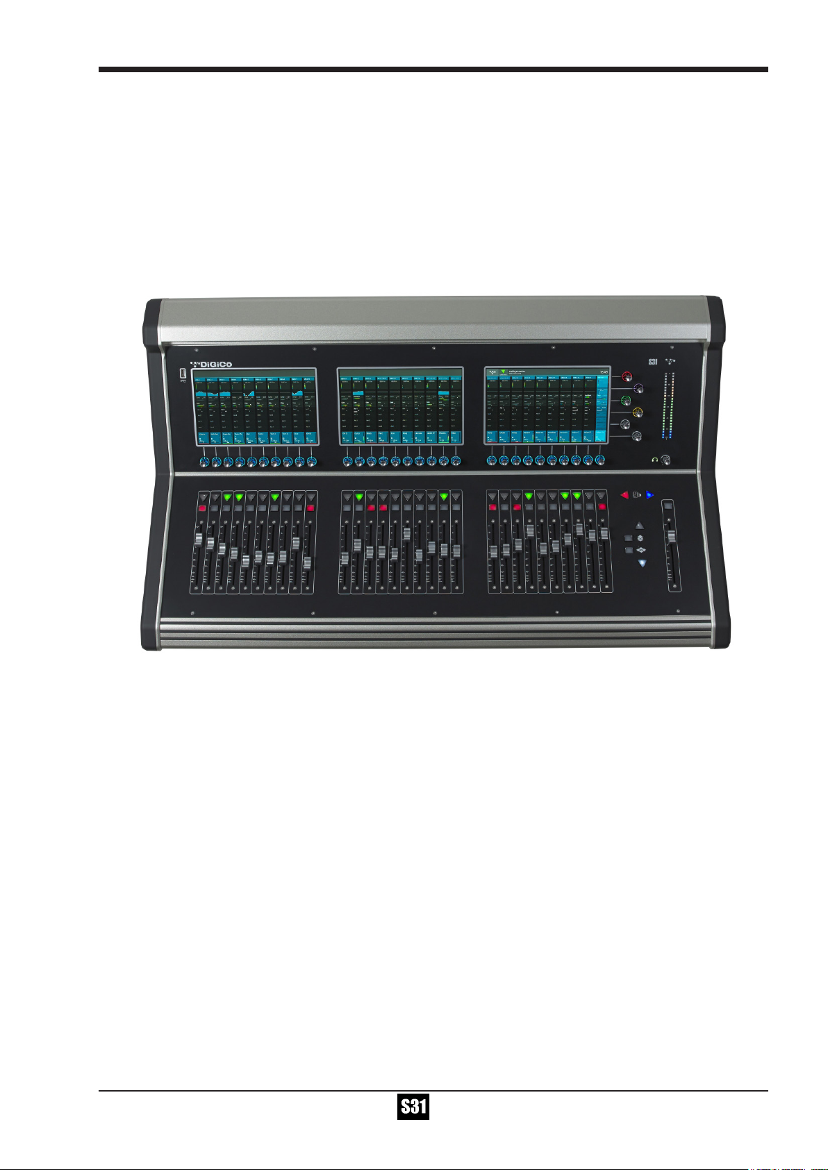
1.1 The Console
The Digico S31 consists of a worksurface, an audio engine and a range of onboard inputs and outputs. It can be connected using optional DiGiCo DMI Cards to a variety of DiGiCo racks and other audio input/output devices.
The console worksurface consists of 3 sections that can be congured to control up to 40 mono or stereo input channels, 10 VCAs, 16
mono or stereo busses plus a Master buss and a 10 Input x 8 Output Matrix.
All 3 sections have 10 assignable faders and 10 sets of assignable on-screen channel controls, the right hand section also has a dedicated Master fader and mute, a Master/Solo meter, a set of 6 assignable encoder/switches and worksurface navigation controls
The console's buss architecture is dynamic, and can support mono and stereo congurations.
Multiple console setups can provide:
Front of House and Monitoring with shared stage racks and gain tracking.
PLEASE NOTE: Some screenshots in this manual only show the centre and
right hand screens (screens 2 and 3) of the S31 which are common to the S21.
S31 and S21 sessions are interchangeable provided that the software version
used on the console is not earlier than the software version that the session
was created in. There is no backward compatitbility of sessions.
1-1
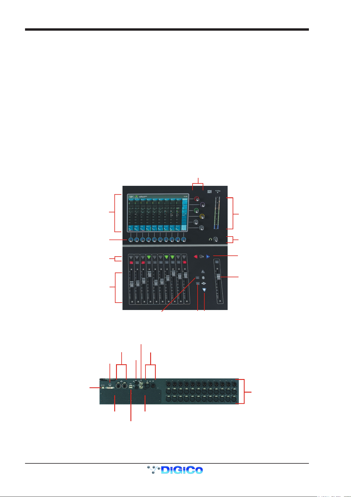
DiGiCo S31
MultiTouch Screen
Assignable Encoder/Switches
Solo & Mute
Channels Faders
Assignable Encoder/Switches
Snapshot Previous/Next
Master/Solo Meters
Headphone Level
Master Fader
Layer Up/Down
Spill Set
Overview
UB MADI Connector
DMI Slot 1 DMI Slot 2
DVI Screen Output
SEE NOTE BELOW
Console Ethernet
Console USB
AES I/O
GPI/O
Word Clock I/O
12 Line Out
24 Mic/Line In
1.2 Before You Start
There are certain general operating principles and terms that should be understood before continuing to use this manual.
Please read this chapter carefully before proceeding.
IMPORTANT NOTES:
S31 V1.3 software is not compatible with any sessions created in preliminary (pre V1.0) versions of S21 software
It is compatible with sessions created in S21 V1.0, V1.0.1, V1.1 and V1.2
The console power switch is situated on the rear panel.
Please ensure that any required DiGiCo I/O racks are connected to the console DMI cards and powered on before start-
ing the console itself to enable automatic discovery of the racks.
DMI cards are NOT "Hot swappable" so please ensure that the console is powered off before inserting or removing
them.
We recommend that the rst snapshot is used as a "Setup" Snapshot where all of your "session wide" settings like
routing, Control Group membership and Buss Modes (whether Busses are Groups or Auxes) are rst stored.
Because these types of setting can be changed with Snapshot recall, it is advisable to save them all into this rst
snapshot before creating any further Snapshots. In this way, the settings for all subsequent Snapshots will contain the
same data and there should be less requirement to adjust the Safe settings in the channels.
1.2.1 Worksurface Layout ...............................................................
IMPORTANT NOTE: The DVI Screen output will display a copy of the Master (right hand) screen but this must be
connected to the HDMI input of a suitable monitor using a standard DVI to HDMI adaptor (not supplied).
IMPORTANT NOTE: The GPI/O functionality is not yet implemented in V1.3
1-2
Rear Panel
DiGiCo S31
Main Menu
1.2.2 Layers and Banks ...................................................................
The S31's worksurface is divided into Layers and Banks. Layers contain 2 or 3 Banks of 10 channels, and the layer which is currently
active on the control surface is selected using the layer up and down buttons next to the Master fader.
The right hand screen is referred to as the Master Screen and this is where the various expanded views of elements such as EQ and
Dynamics are displayed.
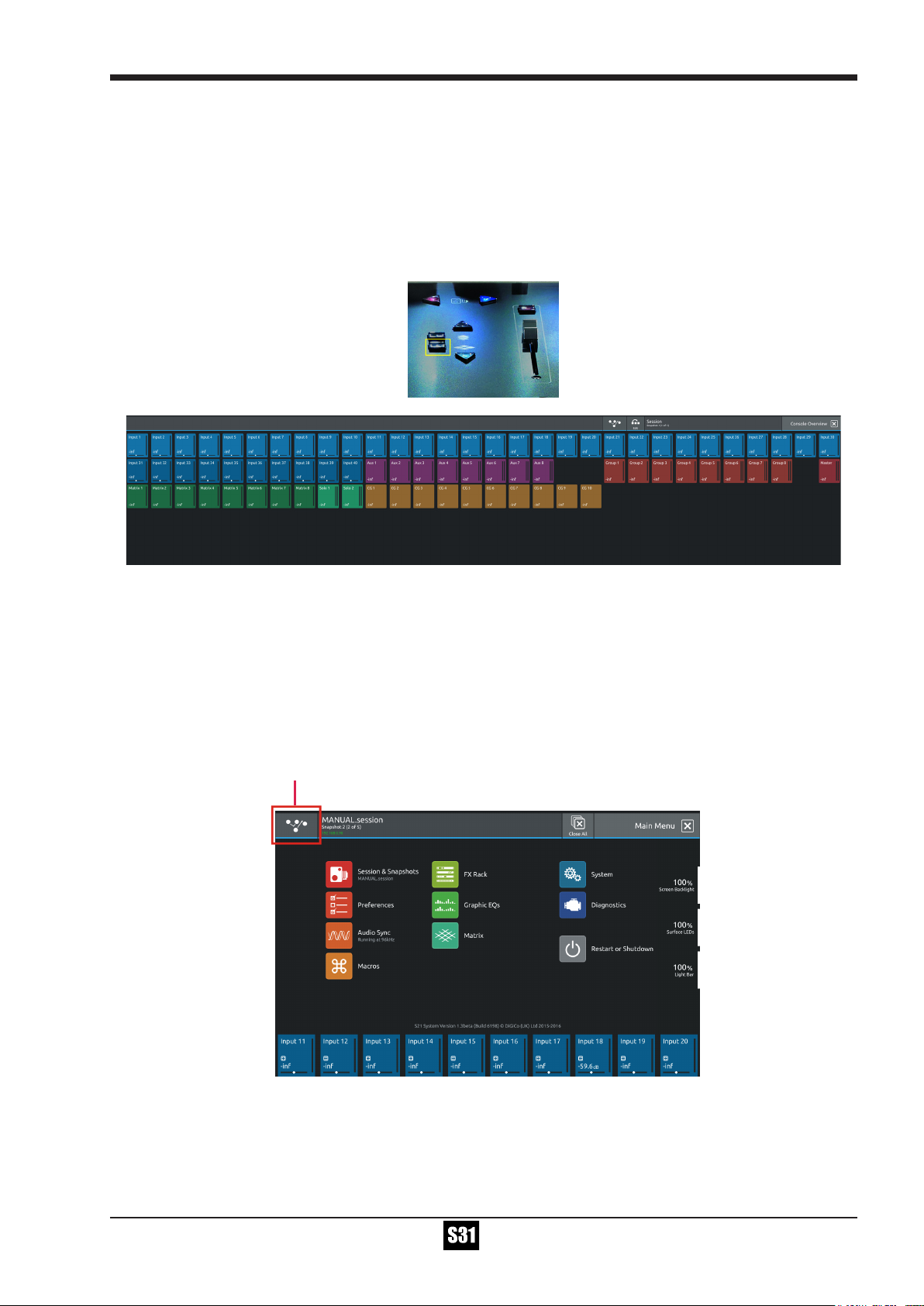
Pressing the white Overview button, located near the layer up and down buttons displays an on screen representation of all console
channels and the active layer can also be selected by touching it on the screen in this mode.The specic channels which are contained
within each Bank are dened in the Overview display. By default, the Input channels will be assigned to Layers 1 and 2
The different output channels will be assigned to Layer 2 and 3. Control Groups will also be assigned to Layer 3. These bank assignments can be customised by the user and saved in a session at any time.
1.2.3 Using the Control Surface .....................................................
There are two main ways in which all of the functions of the S31 are accessed:
1. The touchscreen display, which can be controlled directly using a nger
2. The physical encoders, switches and faders.
A number of functions can be accessed in different ways, allowing users to operate the console using whichever interface they prefer.
All of the physical controls on the console worksurface are described in full within the relevant section of the manual and many require
no further introduction.
The right hand Master Screen has a DiGiCo logo icon at the top which is used to access the Main Menu
1-3
DiGiCo S31
Assignable Encoder/Switches
Selected Channel
Compressor Threshold
Gain & Trim (Push Turn)
HPF
Gate Threshold
Aux Pan (Stereo)
Aux Level
Output Block area
Touch here to select a channel
Selected Channel
Blue = Pan - Default assignment
Touch and Hold in this row
Assigns Gain/Trim and highlights in Red
Touch and Hold in this row
Assigns HPF Freq
and highlights in Mauve
and On/Off
Touch and Hold in this row
Assigns Dynamics 1 Threshold and On/Off
and highlights in Green
Touch and Hold any AUX row
Assigns Aux Send & On/Off
Touch and Hold in this row
Assigns Dynamics 2 Threshold
and highlights in Yellow
and On/Off
Touch the selected channel
in this row to return to
default Pan assignment
1.2.4 The Selected Channel ............................................................
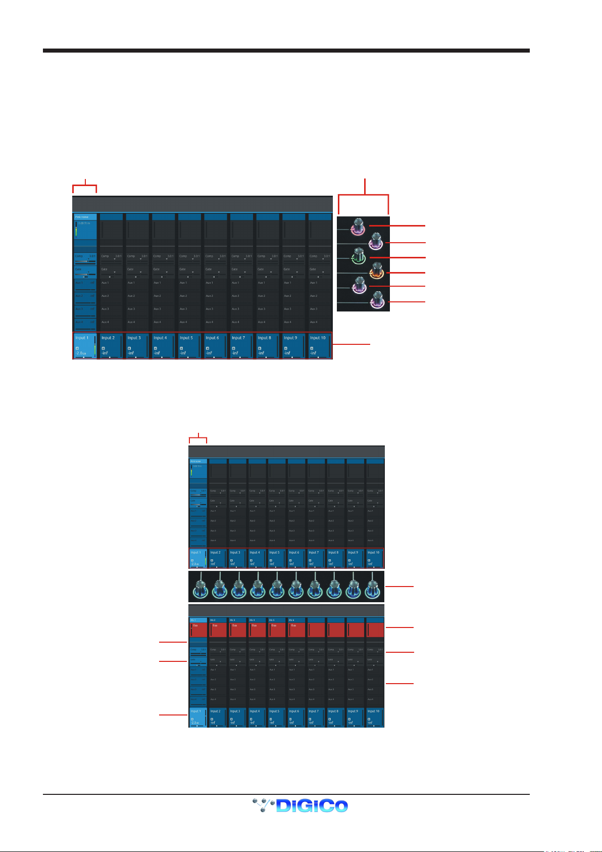
One of the channels in the Channel view is displayed with a highlighted background, indicating that it is currently the Selected Channel.
This means that it has been assigned to the worksurface controls to the right of the screen as shown in the image below. To assign a
channel, touch in the Output Block at the bottom of the on screen Channel view
NOTE: All of the master and under screen rotaries are encoders and switches in one unit.
Often, different functions can be accessed by a standard turn, a push turn and a push (switch)
eg Standard turn = Gain control & Push turn = Trim control
1.2.5 The Under Screen Controls ...................................................
NOTE: When the right hand screen is not displaying the Channel view (eg it is displaying an EQ view), the master
screen worksurface rotaries will not be assigned to the Channel view controls but to the controls for the EQ or other
expanded view instead.
There is a row of 10 encoder/switches immediately below each touchscreen (shown above) that refer to the channels with which they
are aligned.
1-4
DiGiCo S31
Opens Channel Setup view
Opens EQ view
Touch any Aux Send to select the channel
and assign the selected Aux Send to the
6th Master Rotary & Aux Pan to the 5th
(with Aux To Faders option OFF)
Swipe vertically to display more Auxes
Opens Dynamics 1 view
Opens Dynamics 2 view
Touch here to select a channel
These controls give access to the channel pans in standard operation and the surrounding coloured LED rings are blue.
Touching and holding on the rows of controls on screen assign these encoders to different parameters, the screen row changes colour
and the LED rings change to a similar colour.
In the above example the Gain/Trim row at the top of the Channel View has been touched, the row is highlighted in red and the under-
screen controls are assigned to the Gain/Trim function.
Other possible assignments are:
HPF Frequency & On/Off - Row and LED ring highlighted in Mauve
Dynamics 1 Threshold & On/Off - Row and LED ring highlighted in Green
Dynamics 2 Threshold & On/Off - Row and LED ring highlighted in Yellow
Selected Aux row Send level & On/Off - Row and LED ring highlighted in Purple
1.3 The Expanded Views
1.3.1 Display Expanded Views .......................................................
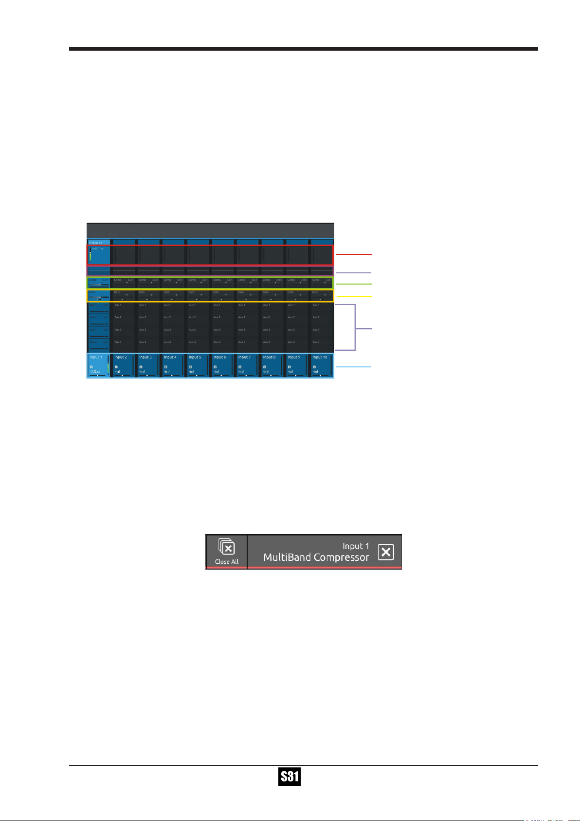
A single touch (rather than a touch and hold) will open a number of different expanded views according to where the touch is made.
The image above shows the various touch areas in the Channel view and the expanded view will be displayed on the Master screen.
Note: When an expanded view is already open, selecting a different channel by touching the Output block area at the
bottom of the screen will change the expanded view to display the newly selected channel.
If an expanded view is already open and a different expanded view is selected, the last view selected will be displayed
on the Master screen with the previously expanded view behind it.
Any combination of expanded views can be "layered" in this way.
The Close All button on the Master screen can be touched at any time to close all active expanded views.
The Close button on the Master screen can be touched at any time to close the currently active expanded view and display the view
beneath it.
1-5
DiGiCo S31
Channel
Name
Column
Title Label
Add To Spill Set
Open Safes View
Ganging
Copy Channel Settings
Recording
Send & Return
Select input source
Filters/Delay/Tubes
Gain Tracking On/Off
EQ
Dyn 1
Dyn 2
Auxes
Direct Out
Groups
Select Solo Assignment
Insert A
Insert B
Master Rotary
Assignment
Channel Mono/Stereo switch
Scroll
To Setup
View
Scroll
To E Q
View
LPF
Delay On/Off
Delay Time
Tube Drive
Tube Bias
Tube On/Off
HPF/LPF Frequency
HPF On/Off
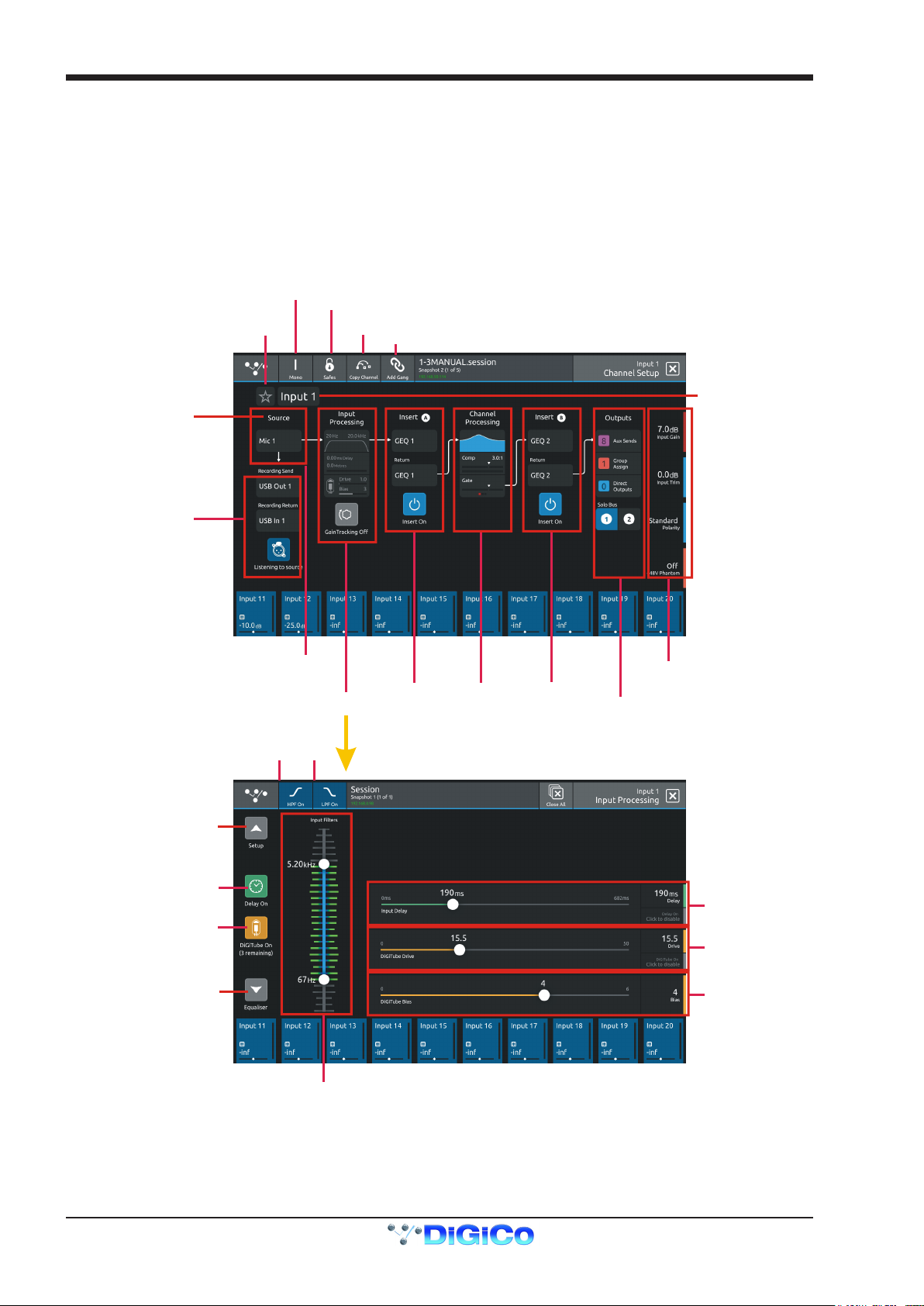
1.3.2 Channel Setup View ...............................................................
Touching the input block at the top of the channel opens the Channel Setup view
Each column represents a section of the channel processing strip and contains blocks which can be selected by touching them.
On screen arrows indicate the signal path from one section of processing to the next
Once a block is selected, the display changes accordingly and the parameters available in that section are assigned to the worksurface
Master Rotaries to the right of the screen.
Note that touching the Filter block or the EQ block will both display the EQ view but with different bands selected.
Note: When any expanded view is open on the Master screen, the Master Rotaries no longer have their standard default assignment and are instead assigned to the parameters in the expanded view which is currently displayed.
1-6
DiGiCo S31
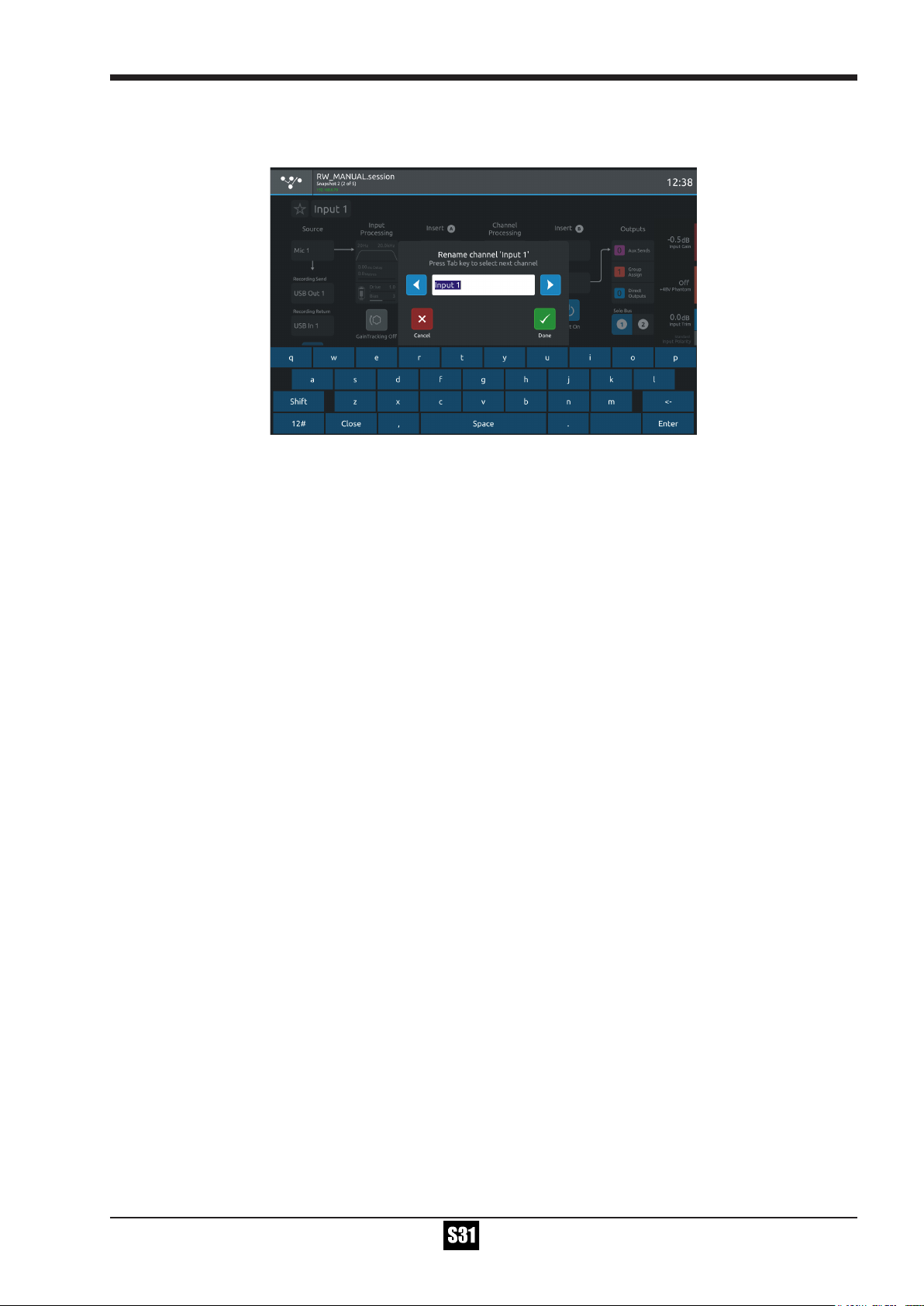
Channel Names can be changed by touching on the existing Channel Name to open the Rename View and then using the Left/Right
scroll buttons to move through channels without closing the Rename View
Touching the Star icon next to the channel name will add the selected channel to the Spill Set (see Spill Set section later in this docu-
ment)
The buttons in the top bar provide the following functions:
Switching the channel from Mono to Stereo mode
Opening the Safes View which allows channel parameters to be protected from Snapshot Recall
Opening the Channel Copy view
Opening the Gang Setup view
Channel Delay, Tube and Filter settings are adjusted by touching in the Input Processing column. This will open an Input Processing View
At the bottom of the input processing column is a switch to turn Gain Tracking On/Off for the channel
Touch the Equaliser button at the bottom left of the screen to switch to the EQ view for the currently selected channel.
To select an Input Route touch the block below the Source label and the Input routing view will open.
To select an Output Route touch the Direct Output block in the Outputs column and the output routing view will open.
To assign the channel to a Group buss touch the Group Assigns button in the Outputs column
To view and adjust Aux Send Options for the channel touch the relevant Aux Sends button in the Outputs column
To select which Solo Busses the channel is assigned to touch the Solo 1, Solo 2 or both Solo 1&2 buttons at the bottom of the Outputs
column
1-7
DiGiCo S31
Source Channel
Setup View
Copy
Button
Select Destination
Channels
Full Copy
Option
Green (Selected)
parameters
will be copied
Confirm
Copy
Copy Channel
Function
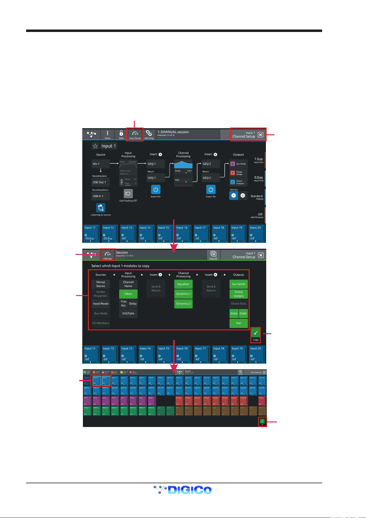
1.3.3 Copy Channel .........................................................................
Multiple settings can be copied from one channel to single or multiple other channels using the Copy Channel button in the Channel
setup view
Open the Channel Setup view for the required source channel by touching the top of its channel strip
Touch the Copy Channel button in the top bar
Touch to select or deselect the parameters that you wish to copy - selected blocks will be highlighted in green
To select/deselect all of the channel parameters that can be copied touch the Full Copy button in the top bar
Touch the Copy button in the bottom right of the screen
Select the Destination channel(s) by touching them on screen - they will have a white outline
Touch the OK button in the bottom right of the screen
1-8
NOTE: Insert and Output routes cannot be copied as they could cause conicts with existing routes
Not all parameter types exist for all channel types so some options might be unavailable
eg Buss mode on an input channel
DiGiCo S31
Add/Edit Gang
Touch to
select
members
Colour coded
members
Touch to remove
or select new
members
OK to
Confirm
OK to
Confirm
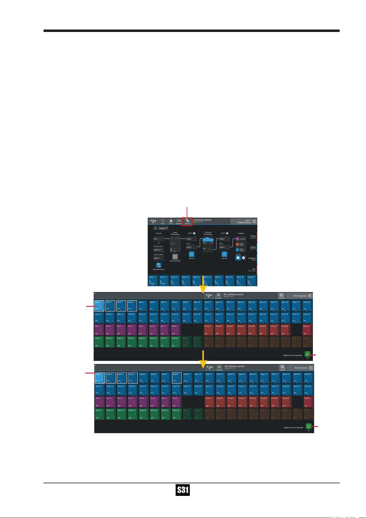
1.3.4 Channel Ganging ....................................................................
Any channel can be ganged (linked) to one or more other channels (up to a maximum of 10 channels) so that changes made on one
will also be made to other members of the gang. This excludes Control Group and Solo channel types.
All level parameters that are measured in dBs (eg faders) will change relatively so moving a fader on one member of the gang by +3dB
will add +3dB to all other members of the gang irrespective of their starting point.
Note: Channel Ganging is limited to a selection of up to 10 channels from anywhere on the console
Multiple gangs can be created but a single channel can only be in one gang at one time
To create a new gang:
Select the rst required member channel of the new gang in the Channel view
Touch the top of that channel to open the Channel Setup View
Touch the Add Gang button in the top bar of the Channel Setup View
Touch the relevant channel blocks in the Pick Channels View to select or deselect members
Touch the OK button to conrm
Members will now be displayed with a colour coded line at top of the output block on each gang member
To edit an existing gang:
Select any member channel of the existing gang in the Channel view
Touch the top of that channel to open the Channel Setup view
Touch the Edit Gang button in the top bar of the Channel Setup View
Touch the relevant channel blocks in the Pick Channels View to select or deselect members
Touch the OK button to conrm
1-9

DiGiCo S31
Parameters that are included in gangs are a xed selection of most standard channel functions but the following elements are not
included:
Routing Input/Output/Insert/Record Send & Return
Mono/Stereo switch
Polarity switch
Analogue socket gain
+48V
Channel & Aux Panning
Parameter Safe Status
CG Membership
Bus Mode
Note: Gang membership cannot be changed with snapshots
Note: Gang members cannot be temporarily isolated from a gang - to change the settings in just one channel, rst
remove it from the gang, make the changes and then add it back to the gang again.
Note: If any element of a gang member is "Flattened" this change will only apply that that member and not to any of the
other members of the gang
Also if settings are copied to any member of a gang, the new settings will only be applied to that member of the gang
and not to any of the other members of the gang
1-10
DiGiCo S31
Record Send and Return Routing
Ripple Route
with
Send+Return
Active
Record Sends
to
40 x UB MADI
Outputs
Listening
To
Source
Listening
To
Copied Audio
Listen to sources
&
Listen to copied audio
Macros
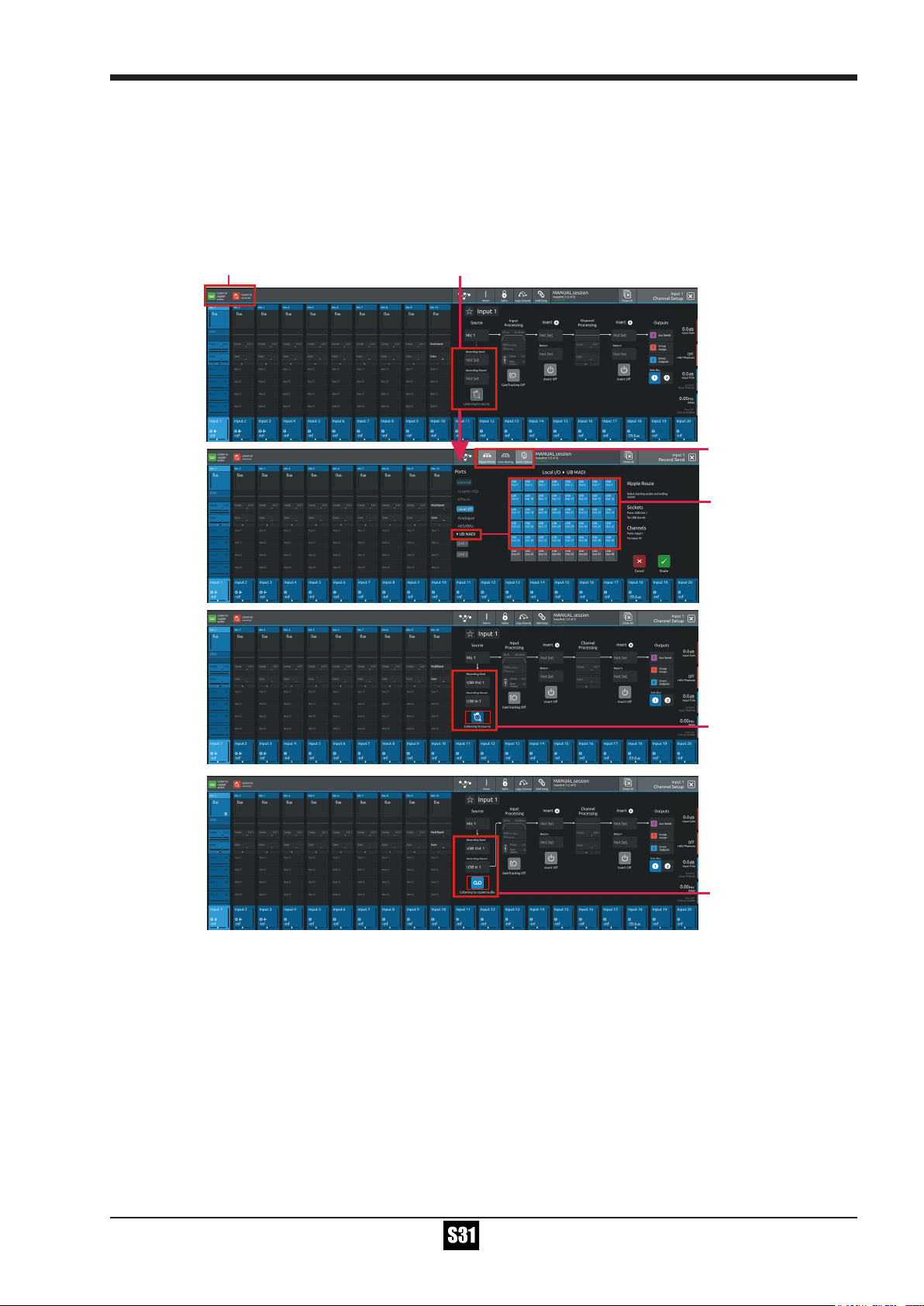
1.3.5 Recording & Virtual Soundcheck ..........................................
Any input channel can be sent from a dedicated pre-processing Record Send point in the channel signal path to any valid output
socket.
Typically a selection of input channel signals would be sent to the console's UB MADI interface for recording on a DAW via a USB connection.
Playback signals from the DAW can the be returned into the dedicated Record Return and switched either individually or globally to
replace the standard input signal to that channel. This is known as Listening to Copied Audio.
To set up a Record Send and Return:
1) Touch the top of the rst input channel that you wish to record to open the Channel Setup View
2) Touch the Recording Send button on the left of the screen to display the Record Send Routing view
3) Ensure that the Send+Return mode is active using the button in the top bar
4) Select an output to feed the recorder by rst selecting a port (eg UB MADI) and then a socket from that port (eg USB OUT 1)
Multiple channel Record Sends can be assigned at the same time using the standard Ripple Route function
5) When the Record Send selections have been made, touch the Route button at the bottom right of the screen to conrm.
6) Select the Channel Setup View again and you will note that the relevant, same numbered input route for the Record Return has auto-
matically been assigned. So if your Record Send was USB Out 1 then your Record Return will be USB In 1
7) The button below the Record Send & Return has 2 states:
a) Listening to Source - the Record signal is being sent and the channel signal is the original Record Send source
b) Listening to Copied Audio - The Record signal is being sent and the channel signal is the Record Return from the recording device
eg Playback signal
1-11
DiGiCo S31
Change Group to Aux
Warning
NOTE: There are 2 Macros available that allow switching of all console Record Sends from Listen to Sources to Listen
to Copied Audio. Using these 2 Macros, the console can be set to monitor record source or record returns globally for
all channels that are being recorded.
Record Sends and Returns do not have to use the console UB MADI Port, they can use any port or combination of ports in any socket
order required. For example, a recording could be made via a MADI DMI card.
A Record Send can be routed to multiple destinations at the same time but a Record Return can only be fed from one input socket at
one time. This is the input socket that will be used when Listen To Copied Audio is active.
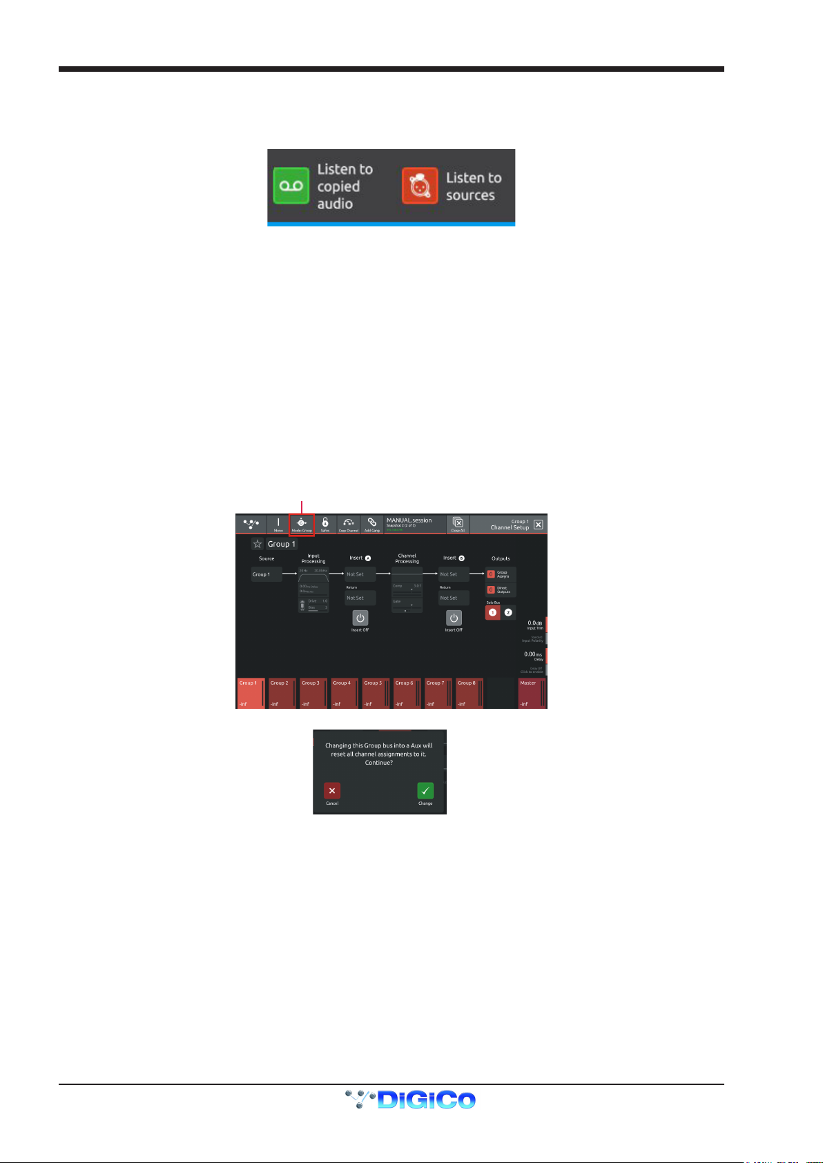
1.3.6 Group and Aux Setup View....................................................
The Group and Aux Channel Setup view are very similar to the Input Channel version but they have one extra function that is used to
convert a Group Buss to an Aux Buss or vice versa
The S31 has a xed number of output busses but they can be changed at any time to be either Auxes or Groups.
In the example below, touching the Mode button on the Group Setup view will change the Group to an Aux but there is warning that all
channel assignments will be reset in the process. So the newly converted Aux will be attened.
The situation is exactly the same when converting an Aux to a Group - all assignments are reset
Note: In Aux/Group Buss Mode can be changed with a Snapshot recall which has its own Safe block. Please ensure
that the buss modes are set in your rst Snapshot before you create any further Snapshots. This will ensure that the
buss mode settings will be consistent in all Snapshots.
1-12
Loading...