


 Loading...
Operation Manual
Issue A, August 2004 for Version 1 Software


Copyright © 2004 Digico UK Ltd
All rights reserved.
No part of this publication may be reproduced, transmitted, transcribed, stored in a retrieval system, or translated into any language in any form by any means without the written permission of Digico UK Ltd. Information in this manual is subject to change without notice, and does not represent a commitment on the part of the vendor. Digico UK Ltd shall not be liable for any loss or damage whatsoever arising from the use of information or any error contained in this manual.
All repair and service of the D1 product should be undertaken by Digico UK Ltd or its authorised agents. Digico UK Ltd cannot accept any liability whatsoever for any loss or damage caused by service, maintenance, or repair by unauthorised personnel.
Software License Notice
Your license agreement with Digico UK Ltd, which is included with the D1 product, specifies the permitted and prohibited uses of the product. Any unauthorised duplication or use of Digico UK Ltd software, in whole or in part, in print or in any other storage and retrieval system is prohibited.
Licenses and Trademarks
The D1 logo and D1 name are trademarks, and Digico UK Ltd and the Digico UK Ltd logo are registered trademarks of Digico UK Ltd.
Microsoft is a registered trademark and Windows is a trademark of Microsoft Corp.
Digico (UK) Ltd
Unit 10
Silverglade Business Park
Leatherhead Road
Chessington, Surrey
KT9 2QL |
|
England |
|
Telephone: |
+44 (0)1372 845600 |
Fax: |
+44 (0)1372 845656 |
Email: |
sales@digiconsoles.com |
WWW:http://www.digiconsoles.com
Manual Issue and Date: Issue A - August 2004 - For Version 1 Software
Licence Agreement
"Product": |
D1 software product produced by Digico UK Ltd intended for use on Target Platform identified below. |
"Target Platform": |
Digico D1 Digital Console system. |
In return for the payment of the one-time fee, the Customer (identified at the end of this Agreement) receives from Digico UK Ltd a licence to use the Product subject to the following terms and conditions.
1.The Product may be used without time limit by the Customer on the Target Platform.
2.The Customer must register the Product with Digico UK Ltd. Registering the Product is deemed an acceptance of the terms and conditions in this agreement.
3.The Product and its licence are not transferable, and the Customer is not permitted to onward-license to any third party. The Customer indemnifies Digico UK Ltd against any and all claims and actions arising from third party use of copies of the
Product made by the Customer.
4.The Customer agrees not to attempt to decompile the object code of the Product otherwise than in circumstances specifically provided for by law, and then only after consultation with Digico UK Ltd.
5.The Customer agrees not to use, or licence the Product for use, with equipment other than the Target Platform.
6.The Customer agrees not to modify the Product without the prior written consent of Digico UK Ltd.
7.This Agreement applies to any enhancement or upgrades that may become available for the Product.
8.This Agreement does not transfer any right, title, or interest in the Product to Customer except as specifically set forth herein.
9.Digico UK Ltd reserves the right to terminate this Agreement upon breach, in which event Customer shall thereafter only be authorised to use the Product to the extent that its contractual commitments to third parties require and then only where such commitments relate to use of the Product as authorised in the foregoing provisions of the Agreement.
LIMITED WARRANTY - Digico UK Ltd warrants for a period of 1 year from the date of purchase of the Product, the Product will reasonably execute its programming instructions when properly installed on the Target Platform. In the event that this Product fails to execute its programming instructions during the warranty period, the Customer's remedy shall be to return the Product to Digico UK Ltd for replacement or repair at Digico UK Ltd option. Digico UK Ltd makes no other express warranty, whether written or oral with respect of this Product.
LIMITATION OF LIABILITY - Except as otherwise expressly provided by law, (a) the remedies provided above are the Customer's sole and exclusive remedies and (b) Digico UK Ltd shall not be liable for any direct, indirect, special, incidental, or consequential damages
(including lost profit whether based on warranty, contract, tort, or any other legal theory.) This agreement is made under the Laws of England.
LICENCE NO: ..................... ..........................................................
REGISTRATION DATE: ..... ..........................................................

WINDOWS USER LICENSE AGREEMENT
IMPORTANT - READ CAREFULLY BEFORE USING EMBEDDED SYSTEM WHICH CONTAINS MICROSOFT SOFTWARE. By using embedded system software, you indicate your acceptance of the following Software License Agreement.
SOFTWARE LICENSE AGREEMENT (Embedded Products)
This software license agreement, including the Warranty and Special Provisions set forth in the appendix or separate booklet included in this package, is a legal agreement between you (either an individual or an entity, hereinafter "End User") and Digico UK Ltd ("Embedded System Manufacturer") of the embedded system containing software product. By using the embedded system on which software program(s) have been preinstalled ("SOFTWARE"), you are agreeing to be bound by the terms of this agreement.
1.GRANT OF LICENSE. This License Agreement permits you to use the Microsoft SOFTWARE as preinstalled on the embedded system.
2.INTELLECTUAL PROPERTY. Virtua contains intellectual property, i.e. software programs, that is licensed for the end user customer's use (hereinafter "End User"). This is not a sale of such intellectual property. The End User shall not copy, disassemble, reverse engineer, or decompile the software program.
3.COPYRIGHT. The SOFTWARE is owned by Microsoft Corporation or its suppliers and is protected by United States copyright laws and international treaty provisions and all other applicable national laws. Therefore, you must treat the SOFTWARE like any other copyrighted material (e.g. a book or musical recording).
4.U.S. GOVERNMENT RESTRICTED RIGHTS. The SOFTWARE and documentation are provided with RESTRICTED RIGHTS. Use, duplication, or disclosure by the United States Government is subject to restrictions as set forth in subparagraph (c)(1)(ii) of The Rights in Technical Data and Computer Software clause at DFARS 252.227-7013 or subparagraphs (c)(1) and (2) of the Commercial Computer Software - Restricted Rights at 48 CFR 52.227-19, as applicable. Manufacturer is Microsoft Corporation, One Microsoft Way, Redmond, WA 98052-6399.
Please see the Warranty for information concerning governing law.
Product support for the SOFTWARE is not provided by Microsoft Corporation or its subsidiaries. For product support, please refer to Embedded System Manufacturer’s support number provided in the documentation for the embedded system. Should you have any questions concerning this Agreement, or if you desire to contact Embedded System Manufacturer for any other reason, please refer to the address provided in the documentation for your embedded system.
For the limited warranty and special provisions pertaining to your Country, please refer to embedded system documentation or the warranty and special provisions booklet included in this package.
APPENDIX: WARRANTY AND SPECIAL PROVISIONS
LIMITED WARRANTY. Embedded System Manufacturer warrants that (a) the SOFTWARE will perform substantially in accordance with the accompanying written materials for a period of ninety (90) days from the date of receipt. Any implied warranties on the SOFTWARE are limited to ninety (90) days. Some states/jurisdictions do not allow limitations on duration of an implied warranty, so the above limitation may not apply to you.
CUSTOMER REMEDIES. Embedded System Manufacturer's and its suppliers' entire liability and your exclusive remedy shall be, at Embedded System Manufacturer’s option, either (a) return of the price paid, or (b) repair or replacement of the SOFTWARE that does not meet the above Limited Warranty and which is returned to Embedded System Manufacturer with a copy of your receipt. This Limited Warranty is void if failure of the SOFTWARE has resulted from accident, abuse or misapplication. Any replacement SOFTWARE will be warranted for the reminder of the original warranty period or thirty (30) days, whichever is longer.
NO OTHER WARRANTIES. The Microsoft Software Programs are provided to the end user "as is" without warranty of any kind, either expressed or implied, including, but not limited to, warranties of mechantability and fitness for a particular purpose. The entire risk of the quality and performance of the software program is with you.
NO LIABILITY FOR CONSEQUENTIAL DAMAGES. Embedded manufacturer’s suppliers shall not be held to any liability for any damages suffered or incurred by the end user (including, but not limited to, general, special, consequential or incidental damages including damages for loss of business profits, business interruption, loss of business information and the like), arising from or in connection with the delivery, use or performance of the software program.
SPECIAL PROVISIONS
This Software License Agreement and Warranty are governed by the law of the State of Washington USA.
Attachment to the License Agreement dated 16 August 1996, between Microprocessor and Memory Distribution Ltd and Soundtracs PLC.

D1 Contents
1.1 The Console ...................................................................................... |
1-3 |
1.2 Hardware ........................................................................................... |
1-4 |
1.2.1 Connections .................................................................................. |
1-4 |
1.2.2 The DiGiConfig Program .............................................................. |
1-5 |
1.3 Getting Started .................................................................................. |
1-6 |
1.3.1 Consoles and Racks .................................................................... |
1-8 |
1.3.2 Loading the Template Session .................................................... |
1-9 |
1.3.3 Selecting an Input Source ............................................................ |
1-9 |
1.3.4 Routing the Channel Signal ....................................................... |
1-11 |
1.3.5 Routing Busses To Outputs ...................................................... |
1-12 |
1.3.6 Save As New File ........................................................................ |
1-13 |
1.3.7 Save Session............................................................................... |
1-13 |
1.3.8 EQ ................................................................................................ |
1-14 |
1.3.9 Dynamics ..................................................................................... |
1-15 |
1.3.10 Auxiliaries .................................................................................. |
1-15 |
1.3.11 Pan / Q Control .......................................................................... |
1-16 |
1.3.12 The Matrix .................................................................................. |
1-16 |
1.3.13 Control Groups ......................................................................... |
1-17 |
1.3.14 Master Fader Banks.................................................................. |
1-18 |
1.3.15 Monitoring ................................................................................. |
1-18 |
2.1 The Input Channels .......................................................................... |
2-3 |
2.1.1 Channel Assignment .................................................................... |
2-3 |
2.1.2 Worksurface Channels ................................................................. |
2-3 |
2.1.3 Input Screen - The Standard View ............................................... |
2-4 |
2.1.4 Input Meters .................................................................................. |
2-4 |
2.1.5 Assigning a Channel .................................................................... |
2-5 |
2.2 Expanding a Processing Module ..................................................... |
2-5 |
2.2.1 Input Module ................................................................................. |
2-6 |
2.2.2 Equaliser Module .......................................................................... |
2-8 |
2.2.3 Dynamics Module ....................................................................... |
2-10 |
2.2.4 Pan / Aux Module ...................................................................... |
2-12 |
2.2.5 Routing Module .......................................................................... |
2-14 |
2.2.6 The ALL Button ........................................................................... |
2-17 |
2.2.7 Undo / Redo Button .................................................................... |
2-17 |
2.2.8 Channel LCD Function Buttons ................................................ |
2-17 |
2.3 Ganging ........................................................................................... |
2-20 |
2.3.1 Creating a Gang .......................................................................... |
2-20 |
2.3.2 Clearing or Editing a Gang ........................................................ |
2-20 |
2.3.3 How a Gang Works ..................................................................... |
2-20 |
|
|

2.4 Layout .............................................................................................. |
2-21 |
2.4.1 External Screens......................................................................... |
2-21 |
2.4.2 Overview Setup ........................................................................... |
2-22 |
2.4.3 Channel Banks ............................................................................ |
2-22 |
2.4.4 Master Banks .............................................................................. |
2-23 |
2.4.5 Move Channels ........................................................................... |
2-24 |
2.4.6 Copy Channels............................................................................ |
2-24 |
2.4.7 Duplicate Channel ...................................................................... |
2-25 |
2.4.8 Channel Overview ....................................................................... |
2-26 |
3.1 Busses and Outputs ......................................................................... |
3-3 |
3.1.1 Buss Outputs Display .................................................................. |
3-3 |
3.1.2 Expanding the Buss Output View ............................................... |
3-4 |
3.2 Output and Buss Controls ............................................................... |
3-4 |
3.2.1 Label .............................................................................................. |
3-5 |
3.2.2 Buss Control Button..................................................................... |
3-5 |
3.2.3 Level Trim ...................................................................................... |
3-6 |
3.2.4 Limiter ............................................................................................ |
3-6 |
3.2.5 Mute ............................................................................................... |
3-6 |
3.2.6 Meters ............................................................................................ |
3-6 |
3.2.7 Output Channel Routing .............................................................. |
3-6 |
3.2.8 Buss Signals as Input Sources ................................................... |
3-7 |
3.2.9 Headphones .................................................................................. |
3-7 |
3.2.10 Output Insert ............................................................................... |
3-7 |
3.3 The Matrix.......................................................................................... |
3-8 |
4.1 Master Section .................................................................................. |
4-3 |
4.1.1 The Master Screen ........................................................................ |
4-3 |
4.1.2 The Menu Buttons ........................................................................ |
4-4 |
4.1.3 Console Security Settings ........................................................... |
4-5 |
4.1.4 Consoles and Racks .................................................................... |
4-5 |
4.2 Configuring the Console .................................................................. |
4-6 |
4.2.1 Session Files Menu ...................................................................... |
4-6 |
4.2.2 The New Session Panel................................................................ |
4-6 |
4.2.3 Clearing Settings .......................................................................... |
4-6 |
4.2.4 The Load Session Button ............................................................ |
4-7 |
4.2.5 The Save As New File Button ...................................................... |
4-8 |
4.2.6 The Save Session Button............................................................. |
4-8 |
4.2.7 USB Data Port ............................................................................... |
4-8 |
4.2.8 Managing Presets ......................................................................... |
4-8 |
4.2.9 Monitoring ..................................................................................... |
4-9 |
4.2.10 Master Section Meters.............................................................. |
4-11 |
4.2.11 Meter Bridge Options ............................................................... |
4-11 |
|
|

4.2.12 Meter Ballistics ......................................................................... |
4-11 |
4.2.13 Restart and Recovery ............................................................... |
4-12 |
4.3 Talkback .......................................................................................... |
4-12 |
4.3.1 Talkback Configuration Button ................................................. |
4-13 |
4.3.2 Talkback Mic Setup .................................................................... |
4-13 |
4.3.3 The Talkback Mixer..................................................................... |
4-14 |
4.3.4 Talkback Presets ........................................................................ |
4-14 |
4.4 Control Groups ............................................................................... |
4-14 |
4.4.1 Creating Control Groups ............................................................ |
4-14 |
4.4.2 Naming Control Groups ............................................................. |
4-15 |
4.4.3 Mode Option................................................................................ |
4-15 |
4.5 Master LCD Function Buttons ....................................................... |
4-15 |
4.6 Snapshots ....................................................................................... |
4-20 |
4.6.1 Master and Relative Snapshots ................................................. |
4-20 |
4.6.2 Storing a Snapshot ..................................................................... |
4-21 |
4.6.3 Recalling a Snapshot ................................................................. |
4-21 |
4.6.4 Replacing a Snapshot ................................................................ |
4-21 |
4.6.5 Update Master ............................................................................. |
4-21 |
4.6.6 Editing Multiple Snapshots ........................................................ |
4-21 |
4.6.7 Moving a Snapshot ..................................................................... |
4-22 |
4.6.8 Renaming a Snapshot ................................................................ |
4-22 |
4.6.9 Deleting a Snapshot ................................................................... |
4-22 |
4.6.10 Snapshot Undo ......................................................................... |
4-22 |
4.6.11 The Snapshot Scope Editor .................................................... |
4-23 |
4.6.12 Channel Scope .......................................................................... |
4-23 |
4.6.13 Controller Scope ....................................................................... |
4-23 |
4.6.14 Snapshot Timing....................................................................... |
4-24 |
4.6.15 Snapshots and MIDI .................................................................. |
4-25 |
4.6.16 MIDI Patches ............................................................................. |
4-25 |
4.7 Macros ............................................................................................. |
4-27 |
4.8 Transport / Timecode Configuration ............................................. |
4-28 |
4.9 Audio Synchronisation ................................................................... |
4-29 |
4.9.1 Internal Sync - Console As Master ............................................ |
4-29 |
4.9.2 External Sync .............................................................................. |
4-29 |
4.9.3 External Sync Sources ............................................................... |
4-30 |
4.9.4 Sample Rate and Conversion .................................................... |
4-30 |
5.1 Configure Effects .............................................................................. |
5-3 |
5.1.1 Selecting Effects ........................................................................... |
5-3 |
5.1.2 Effects and Routing ...................................................................... |
5-4 |
5.1.3 Effects and Auxiliaries ................................................................. |
5-4 |
5.1.4 Output Insert ................................................................................. |
5-5 |

5.2 Effects Control .................................................................................. |
5-6 |
5.2.1 Effects Parameters ....................................................................... |
5-6 |
5.2.2 Output Processing Parameters ................................................... |
5-6 |
5.3 Processing Channels ....................................................................... |
5-8 |
5.3.1 Inserting Processing Channels ................................................... |
5-9 |
5.3.2 Processing Channel Controls ................................................... |
5-10 |
6.1 FOH and Monitors Setup .................................................................. |
6-3 |
6.1.1 Gain Tracking Settings................................................................. |
6-5 |
6.1.2 Gain Tracking Procedures ........................................................... |
6-5 |
6.1.3 Gain Tracking and Snapshots ..................................................... |
6-6 |
6.2 Redundancy and Mirroring .............................................................. |
6-7 |
6.2.1 Redundant Optical Loop .............................................................. |
6-7 |
6.2.2 Redundant Mirror Console or Engine ......................................... |
6-7 |
6.2.3 Sync Session ................................................................................ |
6-9 |
6.2.4 Mirroring ........................................................................................ |
6-9 |
6.2.5 DiGiRack Control ........................................................................ |
6-10 |
6.3 PC Remote Control......................................................................... |
6-13 |
6.3.1 Remote PC Setup........................................................................ |
6-13 |
6.3.2 Remote PC Operation ................................................................ |
6-13 |
7.1 Troubleshooting................................................................................ |
7-3 |
Index ........................................................................................................ |
8-1 |

Chapter 1
Chapter 1
Getting Started
1-1

Chapter 1
1-2
Chapter 1
1.1 The Console
The Digico D1 consists of a worksurface, and up to 4 Input/Output Rack Units. The Rack Units are connected to the console by MADI links (or optical fibre optionally), which carry all the audio input and output signals.
The console worksurface consists of 2 Input Banks, and a Master Section.
Each input bank has 8 assignable faders and 8 sets of assignable on-screen channel controls, the Master Section has 8 assignable faders and a master fader. The Master section controls outputs, monitoring and configuration.
The console's buss architecture is dynamic, and can support stereo, LCR(S) and 5.1 configurations. Multiple console setups can provide:
Front of House and Monitoring with shared stage racks and gain tracking. Redundant Mirroring of Front of House and/or Monitoring consoles.
Remote control of console via an ethernet link with a laptop computer.
This manual is divided into chapters, each dealing with one aspect of the console.
•Chapter 1 is a quick start guide that provides an overview of the basic console functions.
•Chapter 2 describes how to use the assignment and channel controls provided on an Input channel bank.
•Chapter 3 describes the Output channels, including Group, Direct, Aux and Matrix Outputs.
•Chapter 4 describes most of the Master Section functions, including console configuration, monitoring, snapshots, and timecode and transport control.
•Chapter 5 describes the onboard Effects and Processing Channel Modules.
•Chapter 6 describes the various functions of multiple console setups.
•Chapter 7 provides help with troubleshooting common problems.
1-3
Chapter 1
1.2 Hardware
1.2.1 Connections .........................................................................
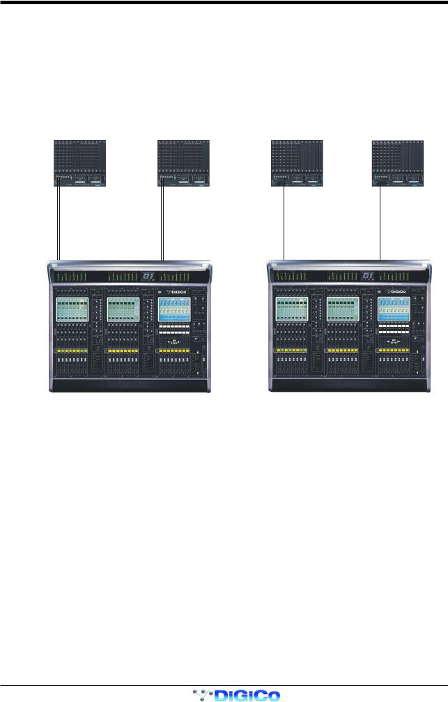
Detailed information on the various systems of connection is provided in the Interconnection and System Setup Manual but the following diagram provides an overview of a single console setup.
The D1 may be connected to the DiGiRacks with MADI coaxial cables (standard) or with optical fibre (optionally).
There are 2 sets of MADI In/Out ports on the rear panel of the console labelled MADI 1 and MADI 2. The DiGiRacks also have 2 sets of
MADI In/Out ports labelled Main MADI and Auxiliary MADI.
If the D1 has an optical fibre option, there will be optical fibre ports A and B on each device. Connections are as follows:
CONNECTION WITH MADI |
CONNECTION WITH OPTICAL FIBRE |
MAIN MADI IN MAIN MADI OUT |
MAIN MADI IN MAIN MADI OUT |
OPTO A |
OPTO B |
OPTO A |
OPTO B |
|
|
OPTIONAL
REDUNDANT
LOOP
MADI PORT 1 OUT MADI PORT 1 IN |
MADI PORT 2 OUT MADI PORT 2 IN |
OPTO A |
OPTO B |
Detailed information on multiple console setups is provided in a separate chapter of this manual.
1-4
Chapter 1
1.2.2 The DiGiConfig Program .....................................................
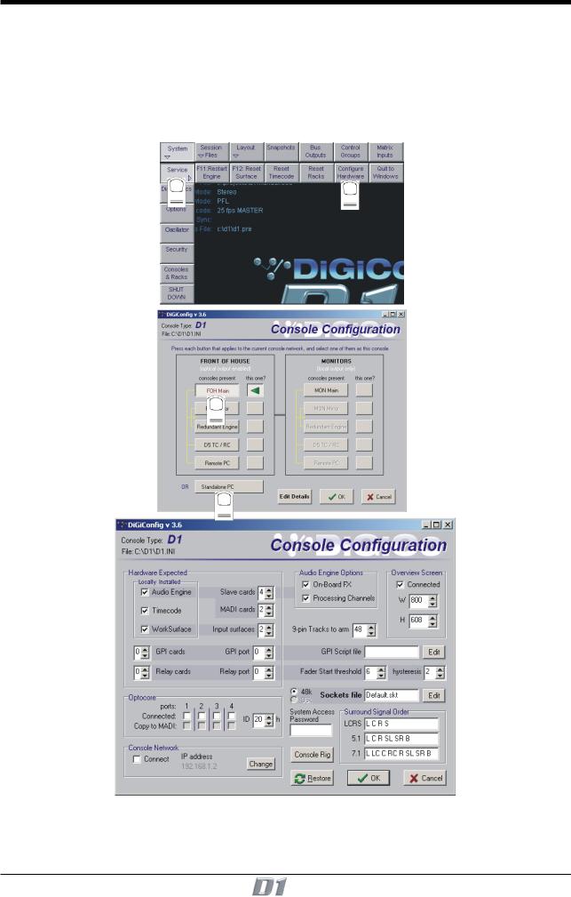
The following example shows how to run the DiGiConfig program from the D1 software in order to configure you hardware:
1)Open the System / Service menu.
2)Press the Configure Hardware button, the D1 software will close and DiGiConfig will open.
3)Press the relevant buttons for all the consoles that you wish to configure - in the example, a single FOH Main console is selected.
Press the This One button to select the console that you are working on.
4)This will apply the correct configuration but the details can be further edited by pressing the Edit Details button.
5)Press OK to return to D1 software.
1 |
2 |
|
3
4
1-5
Chapter 1
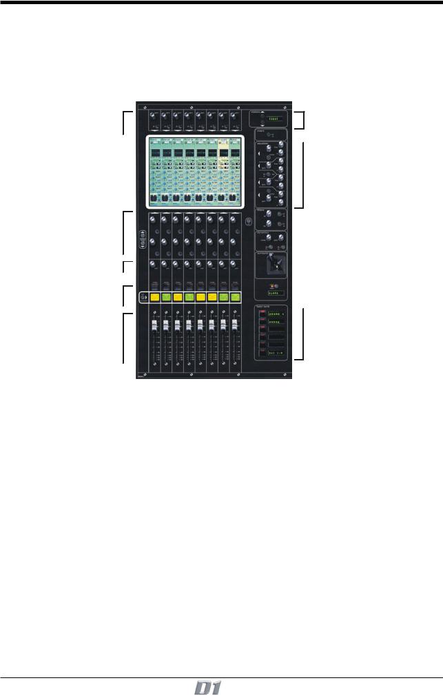
1.3 Getting Started
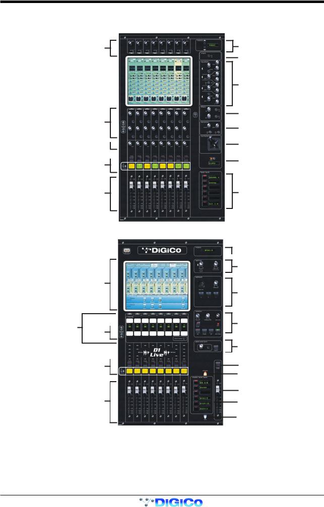
Input Section
Input Gain and Phase
Aux / Pan / Dynamics Controls
Pan / Q Control
Mute and Interactive LCD 
Function Button
Channels Faders
Master Section
Master Screen
Macros Screen 
Scroll
Mute and Interactive LCD 
Function Button
Output / Control Group
Faders
Channel Meter Status
Channel Insert On / Off
4 Band Parametric EQ
High and Low Pass Filters
Dynamics Thresholds and On / Off
Joystick
Undo / Redo Button
Channel Fader Banks
 Meter Status
Light Controls
Talkback
Monitoring
Matrix/Effects Controls
Master Mute
Previous Snapshot
Master Fader
Master Fader Banks
Next Snapshot
1-6

Chapter 1
Input Channel
Input Gain
Phase/
Gain Tracking On/Off
|
|
|
|
|
|
Input Module |
|
|
|
|
|
|
Analogue Gain |
|
|
|
|
|
||
|
|
|
|
|
|
Digital Trim |
|
|
|
|
|
|
EQ Module |
|
|
|
|
|
|
|
|
|
|
|
|
||
|
Aux Send & Compressor Controls |
|
|
|
|
Dynamics Module |
|
|
|
|
|
||
|
|
|
|
|
||
|
|
|
|
|
|
|
Screen Scroll |
Aux On/Off & Compressor Controls |
|
|
|
|
|
|
|
|
|
|
||
Aux Send & Gate Controls |
|
|
|
|
|
|
|
|
|
|
|
|
|
|
Aux On/Off & Gate Controls |
|
|
|
|
|
|
Pan/Q Control |
|
|
|
|
|
|
Mute |
|
|
|
|
Aux / Pan Module |
|
|
|
|
|
||
|
|
|
|
|
|
|
LCD Function |
Interactive LCD Button |
|
|
|
|
|
|
Channel Fader |
|
|
|
|
Routing Module |
|
|
|
|
|
||
|
|
|
|
|
|
|
|
|
|
|
|
|
|
Master Screen
1-7

Chapter 1
1.3.1 Consoles and Racks ............................................................
If the console is the only one in the system, the Consoles & Racks panel will not open automatically and the console will be fully connected to the racks with its Master Audio Outputs Active by default. This panel can also be opened from the System menu.
If the system has been defined as consisting of more than one device, the Consoles & Racks panel will automatically open on boot up or load session.
If the crossed Ethernet cable or Ethernet switch has been connected, then the Ethernet Connected line should show a green OK light and not a red cross.
The initial state will have no connection between the devices (Independent) or the racks (Isolated) and the panel appears in order to prompt the operator to make the necessary connections.
In this state, any gain adjustments made on the console will have no effect as the racks will not be receiving any data.
The console’s MASTER Audio Outputs Active button will normally be highlighted in orange to show that it is the master responsible for audio processing at this time.
The same button on the other consoles in the system should not be highlighted at all.
The MADI Rack’s connect states Receive Only and Full Connect are enabled/disabled and set according to the Audio Master active state
– an inactive engine cannot output to a MADI rack.
Main Console |
Redundant Engine, Mirror Console or Remote |
To enable control of the DiGiRacks, press the Full Connect buttons for the Optocore and MADI racks. You will then be required to confirm the action, the session settings will be sent to the racks and the console will have full control over them.
If you have a system where more than one console is sharing the racks you may wish to use the Receive Only mode where the console will receive the rack’s existing settings but will not be able to control the gain on the racks.
Options are:
Isolate where the console will not communicate with the racks and therefore any adjustment of input gain or +48V switch will have no effect on the rack settings.
Receive Only where the console will receive the rack’s existing settings but will not be able to control the gain etc on the racks. Full Connect where the console will send its settings to the racks and change them accordingly.
For more information on the use of this panel please see the chapter on Multiple Console Setups.
1-8

Chapter 1
1.3.2 Loading the Template Session ...........................................
A basic template session (default configuration) is provided with the console. To load it:
1)Touch the Session Files button at the top of the Master Screen to view the menu.
2)Touch the Load Session button in the Sessions menu to open the Load Session panel.
3)Touch the Projects folder button at the bottom of the panel to view its contents.
4)Touch the template.ses entry in the file list to highlight it.
5)Touch the Load button in the bottom right of the panel to open the session file.
1
2
4
5
3
This will provide you with a configuration where 56 or 96 microphone inputs are already selected as input sources and some basic output routing is in place. However, the following instructions will help you to check or change the basic configuration and then save your custom setup as a new session file.
1.3.3 Selecting an Input Source ...................................................
First select the Fader Bank that you require by pressing one of the bank of buttons next to the channel faders. Holding a Fader Bank button for more than half a second will switch all input banks to view the same Fader Bank row.
1-9
Chapter 1
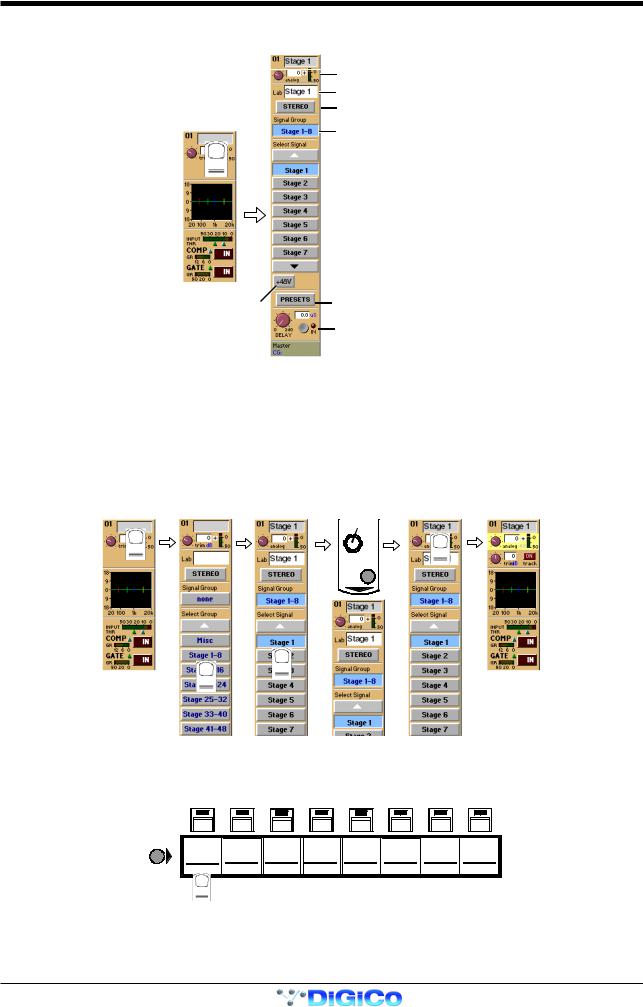
You can display the Input Module for a fader by touching the top of the fader's on-screen channel strip, where the channel label is displayed. You can then hide the module by touching the same area again.
Gain / Phase
Signal Label
Stereo Channel Mode Selector
Signal Group Selector
Signal Selector
Phantom Power |
Preset Selector |
(Mic i/p only) |
|
|
Signal Delay |
Input sources are divided into groups of signals eg. Stage 1-8 or Line 1-16.
To select an input source:
1)Touch the top of the input screen to open the input panel.
2)Touch the name of the Signal Group to view the signal names.
3)Touch the name of the signal to assign it to the channel.
4)Adjust the gain (analogue rack gain or digital trim selected by touching the required on screen control) with the worksurface rotary control at the top of the channel.
5)Touch the top of the input screen again to return to the standard view.
Note: Touch the Lab box and type a name for the channel if required.
GAIN
1 |
5 |
|
4
3
2
If the Stereo is pressed, the input channel functions will control two input signals, the one which has been selected and the next one in the rack.
eg. If Stage 1 is selected and the stereo button is pressed Stage 2 will also be controlled.
To Solo a channel use the Channel LCD Buttons just below the mute buttons in the channel strip.
mute |
mute |
mute |
mute |
mute |
mute |
mute |
mute |
LCD |
|
|
|
|
|
|
|
|
FUNCTION |
01 Mo |
02 Mo |
03 Mo |
04 Mo |
05 Mo |
06 Mo |
07 Mo |
08 Mo |
|
MIC 1 |
MIC 2 |
MIC 3 |
MIC 4 |
MIC 5 |
MIC 6 |
MIC 7 |
MIC 8 |
|
PFL |
PFL |
PFL |
PFL |
PFL |
PFL |
PFL |
PFL |
|
|
|
|
|
|
|
|
|
1-10
Chapter 1
These are multi-function buttons and by pressing the Channel LCD Function button on the left hand side you can select which function they are currently assigned to.
LCD
FUNCTION
|
|
AUX SEND |
BUILD |
SOLO |
ONLY |
FADER |
SOLO |
|
SOLO |
SAFE |
DISPLAY |
ASSIGNS |
ASSIGNS |
||||
>FADERS |
GANGS |
1 OR 2 |
||||||
|
|
NAME |
CHANNEL |
CHANNEL |
||||
|
|
|
|
|
12
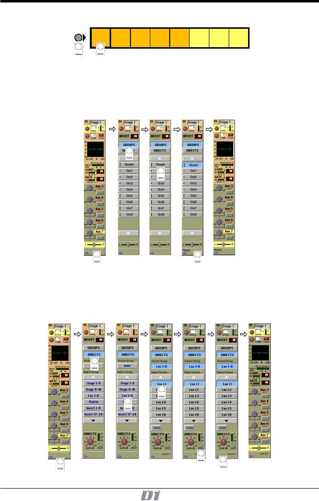
1.3.4Routing the Channel Signal ................................................
The channel signal can be routed to Groups and Direct Outputs.
To Route to a Group:
1)Touch the bottom of the input screen to open the routing panel.
2)Touch the Groups button if it is not already highlighted.
3)Touch the Group button(s) that you require eg. Master, Grp1 etc
4)Touch the bottom of the input screen again to return to the standard view.
2
3
1 |
4 |
To Route to a Direct Output:
1)Touch the bottom of the input screen to open the routing panel.
2)Touch the Directs button if it is not already highlighted.
3)Touch the name of the Socket Group to view the output socket names.
4)Touch the Output Socket button(s) that you require eg. Loc L1, Loc L2 etc.
5)Touch the Pre/Post button to specify the position of the Direct Out, relative to the channel fader, in the signal path.
6)Touch the bottom of the input screen again to return to the standard view.
2
4
3
|
5 |
1 |
6 |
|
1-11
Chapter 1
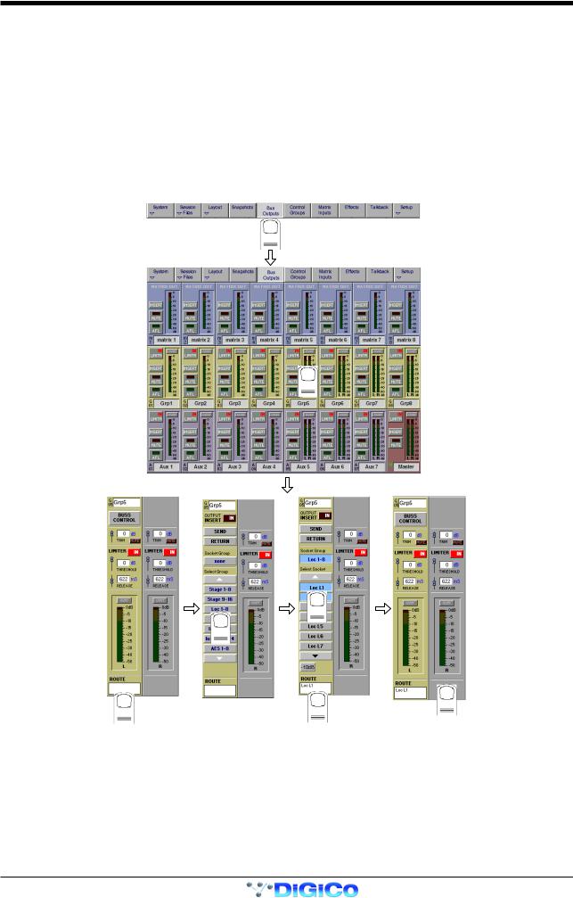
1.3.5 Routing Busses To Outputs ...............................................
The Master, Group, Auxiliary and Matrix busses must be routed to output sockets as part of the initial configuration.
This is achieved by using the buss output routing panel in the Master Screen:
1)Touch the Buss Outputs button at the top of the master screen.
2)Touch the on screen meter of the relevant buss to expand the view.
3)Touch the Route button at the bottom of the panel.
4)Touch the name of the Socket Group that contains the output you require eg. Loc 1-8.
5)Touch the Output Socket button(s) that you require eg. Loc L1, Loc L2 etc
6)Touch the Route button at the bottom of the panel to close the routing.
7)Touch the area around the on screen meter to return to the standard view.
8)Press the Master Fader Bank button for the relevant row of outputs to adjust the output level with the worksurface master faders.
NOTE: For a stereo buss, select the output for the left hand signal and the next consecutive output is used automatically for the right hand signal.
1
2
5
4
3 |
6 |
7 |
|
1-12
Chapter 1
1.3.6 Save As New File ..................................................................
When you change the configuration of the template session you should save it to the console's flash drive under a new filename.
1)Touch the Session Files button at the top of the Master Screen to view the menu.
2)Touch the Save as New File button in the Sessions menu to open the panel.
3)Touch the Projects folder button at the bottom of the panel to select the file destination.
4)Touch the New Filename box and type the chosen name (with a maximum of 8 letters and no punctuation).
5)Touch the Session Title box and type a description of the session if required.
6)Touch the Save button in the bottom right of the panel to save the session file.
Note: If you touch a session name on the existing list, this name will automatically be selected as the new file name and touching Save will overwrite the old file.
1
2
4 |
5 |
6
3
1.3.7 Save Session ........................................................................
This button which is found above the Save As New File button will save the existing session in the same location and under the same file name as it was previously saved or loaded from. It therefore serves as a "Quick Save" option to update an existing session.
Remember that this function will overwrite your last saved version.
If you wish to save the session under a new name use the Session Files menu button and select Save As New File (See above).
1-13
Chapter 1
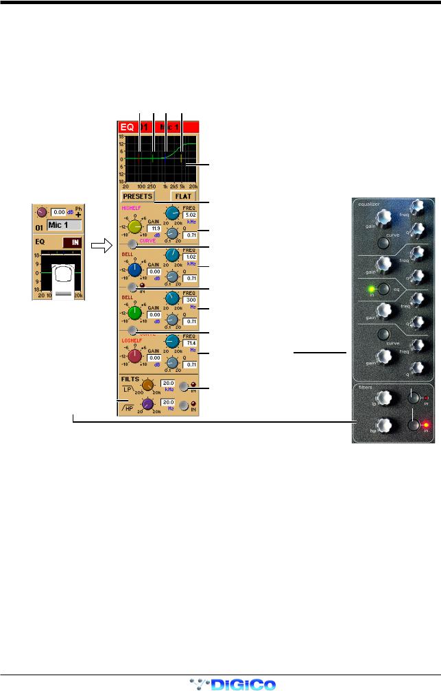
1.3.8 EQ ..........................................................................................
The EQ section comprises four user-configurable parametric filters and a pair of swept High-pass and Low-pass filters.
The EQ is accessed by touching the on screen display to Assign the channel (the colour changes to orange) and then using the controls on the right hand side of the input module.
When a control is adjusted the expanded view seen below appears in the input screen but this view can be seen at any time by touching the EQ response graph on the screen.
NOTE: If the expanded view does not appear when a control is adjusted open the System / Options panel and press the Automatically expand EQ view when adjusted button.
Filter Centre Frequencies
Response Graph
 Reset EQ
Preset Selector
Parametric 1 (Yellow) 
Curve Select for Parametric 1 
Parametric 2 (Blue)
EQ In/Out 
Parametric 3 (Green) 
Curve Select for Parametric 4 
Parametric 4 (Red)
Lopass In/Out 
Hipass / Lopass Filters
 Hipass In/Out
Note: The four band EQ and each of the filters have their own in/out switches.
The type of filter used by bands one and four can be changed by successive presses of the Curve Select button for that band. There are three possible settings for each band.
1-14

Chapter 1
1.3.9 Dynamics ..............................................................................
The dynamics are accessed by touching the words Comp or Gate just below the EQ graph on screen to open the dynamics panel.
The worksurface controls beneath the screen control the various parameters. Touching the panel again will close it.
Dedicated Threshold controls and In/Out switches can be found on the right hand side of the input section worksurface. These can control the Assigned channel's dynamics whether the on screen dynamics panel is open or not.
Compressor Controls
Gate Controls
The third row of buttons in the input section can be assigned to any of the dynamics on/off switches. Hold the Assign Switch button on the left of the input section and touch the dynamics section on the screen. The selected control is shown by the Status Display.
Note: These switches can also be assigned to other functions - See section 2.1.3
1.3.10 Auxiliaries ...........................................................................
The auxiliaries are accessed by touching the auxiliary row on screen or using the Screen Scroll buttons on the left of the input section.
Aux Sends
Aux On/Off and Pre/Post
Screen Scroll
Aux Sends
Aux On/Off and Pre/Post
1-15
Chapter 1
Using either of these methods, the highlighted auxiliaries on the input screen will change. The rotary controls and switches beneath the screen are used as auxiliary sends, pans, on/off and pre/post switches in the following way.
MONO AUX |
STEREO AUX |
FIRST MONO AUX SEND |
STEREO AUX SEND |
FIRST MONO AUX ON/OFF |
STEREO AUX ON/OFF |
(PRE/POST WHEN SEND IS DOWN) |
(PRE/POST WHEN SEND IS DOWN) |
SECOND MONO AUX SEND |
STEREO AUX PAN |
SECOND MONO AUX ON/OFF |
STEREO AUX PAN |
(PRE/POST WHEN SEND IS DOWN) |
TOGGLE TO CENTRE |
|
|
1.3.11 Pan / Q Control ................................................................... |
|
The third rotary control in the section is a dedicated pan.
It also serves as a "Q" control for the 6 band parametric EQ if an insertable processing channel is selected on the screen.
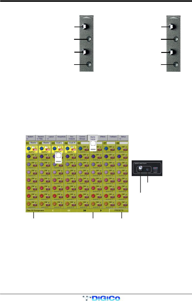
1.3.12 The Matrix ...........................................................................
The 38x8 way matrix is accessed by touching the Matrix Inputs button on the master screen or the Matrix button on the far right of the worksurface master section.
Inputs are selected in the same way as the input channels (See Section 1.3.1).
Touch the on screen matrix send controls to select which ones you wish to adjust and they will become highlighted.
Use the worksurface Point and Turn control and On/Off switch to adjust the settings for all highlighted sends.
At the bottom of the panel there are buttons to Clear All Assignment, Load and Save Presets and Scroll buttons to view the other inputs.
|
1 |
|
2 |
Open Matrix |
|
|
|
|
|
|
|
Send On/Off
Matrix Send
Clear All Selections |
Scroll Inputs |
Matrix Presets |
1-16
Chapter 1
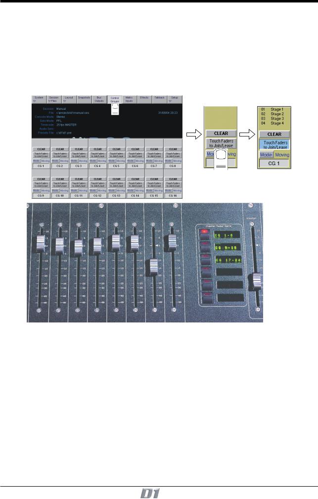
1.3.13 Control Groups ..................................................................
Any number of input channels and output channels can be connected to one or more of the Control Groups. They can then all be operated from a single worksurface control. Changes to the Control Group fader, mute or solo or controls will affect all channels connected to the group.
To set up Control Groups:
1)Touch the Control Groups button on the Master screen.
2)Touch the Touch Faders To Join/Leave button on the required Control Group (1-16).
3)Touch the faders on the channels that you want to include. (Touching the fader again will remove it from the group).
4)Touch the Touch Faders To Join/Leave button again to turn the function off.
5)Press the on screen Mode button to select Moving faders, VCA style static faders or Mutes only.
6)Use the worksurface fader, mute and solo to adjust settings for the Control Group members.
A list of all the connected channels and their names is displayed above each Control Group display, touch the area above the Clear button to expand this list.
When a fader is touched it is highlighted in the list.
You can also clear all the channels from a Control Group by pressing Clear.
When a channel is a member of a Control Group, its own controls can still be adjusted independently of the other Group members.
Adjustments to fader levels are transmitted to the Group members as dB changes, so that a level increase of 2dB on the Group fader will increase all the member levels by 2dB, irrespective of the relative levels of the individual channel faders.
1-17
Chapter 1
1.3.14 Master Fader Banks ...........................................................
The faders in the console Master section control the output levels for busses, auxiliaries, control groups and the matrix. If configured using the Master LCD Function buttons (Section 4.5 of this manual), they may also control input channel levels.
To select a bank, press the relevant Master Fader Bank button.
Note: To assign the alternative set of Master Fader Banks to the worksurface, open the Layout/Master Banks panel and press the Flip Banks button
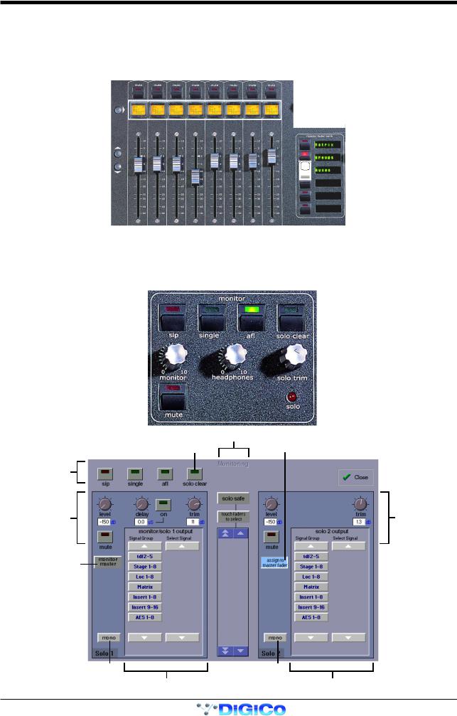
1.3.15 Monitoring ..........................................................................
The Monitoring panel can be found under the Setup Menu on the Master Screen and some of the controls can be accessed on the right hand side of the Master worksurface.
It may be accessed at any time to change the monitoring setup.
|
Solo Safe |
Clear All Solos |
Assign Solo 2 Level |
to Master fader |
Solo Modes
Solo 1 Controls |
Solo 2 Controls |
Monitor Master Buss
When No Solo On
Set Solo 1 Mono |
Set Solo 2 Mono |
Route Solo 1 To Output |
Route Solo 2 To Output |
1-18

Chapter 1
There are two solo busses and each console solo button can be independently assigned to use Solo 1 or Solo 2. Output solos may use a total of 16 inputs to each solo buss.
Therefore, if the console was being used for stage monitors, the first solo buss could feed an "in ear" monitor and the second solo buss could feed a wedge.
To use Solo 2 there must be sufficient busses available (at least two) and if Solo 2 does not appear on the panel a new session should be created to make these busses available.
The dedicated worksurface buttons control the relevant Monitor/Solo 1 functions and the Solo 2 level and trim may be controlled by touching the on screen control and using the Matrix rotary control on the worksurface.
For more information on Monitoring and Solo options see Section 4.2.9.
1-19

Chapter 2
Chapter 2
Inputs and Console Channels
2-1

Chapter 2
2-2
Chapter 2
2.1 The Input Channels
The console Worksurface consists of a Master section, and two "Banks" of faders for controlling input channel or auxiliary levels. Internally, the console has between 64 and 160 (according to the model) processing channels.
2.1.1 Channel Assignment ...........................................................
The assignment of audio input channels to faders on the D1 worksurface is "soft", so that there is no direct link between channels and faders. The console has between 40 and 224 (according to the model) inputs which are then assigned in blocks of eight to the console's physical fader banks.
Input Gain and Phase |
|
|
|
|
|
|
Channel Meter Status |
|
|
|
|
|
|
||
|
|||||||
|
|
|
|
|
|
|
Channel Insert On / Off |
|
|
|
|
||||
|
|
|
|
|
|
|
|
|
|
|
|
|
|
|
4 Band Parametric EQ |
|
|
|
|
|
|
|
|
Aux / Pan / Dynamics Controls |
|
|
|
|
|
|
High and Low Pass Filters |
|
|
|
|
|
|
||
|
|
|
|
|
|
Dynamics Thresholds and On / Off |
|
|
|
|
|
|
|
||
|
|
|
|
|
|
|
|
|
|
|
|
|
|
|
|
Pan / Q Control |
|
|
|
|
|
|
Joystick |
|
|
|
|
|
|
||
|
|
|
|
|
|
Undo / Redo Button |
|
Mute and Interactive LCD |
|
|
|
|
|
|
|
|
|
|
|
|
|
||
Function Button |
|
|
|
|
|
|
Channel Fader Banks |
Channels Faders |
|
|
|
|
|
|
|
|
|
|
|
|
|
||
|
|
|
|
|
|
||
|
|
|
|
|
|
|
|
When you want to access an input channel which is not currently visible on a worksurface channel, press the relevant Fader Bank button on the console worksurface.
Note: Holding a Channel Fader Bank button for more than half a second will switch both input surfaces to their equivalent bank for the same bank button
2.1.2 Worksurface Channels ........................................................
Each fader bank has eight channels. Each channel has a Mute switch, an Interactive LCD button which performs a number of different functions and assignable rotary controls and switches to control auxiliaries and dynamics functions.
As well as a number, each channel has a Label which you can define. Labels can be up to 31 characters but only the start of the label will be displayed. The number of characters displayed depends on the character width.
Above the faders on each bank, the touch-screen provides access to the routing and processing for each channel.
2-3
Loading...