


SD5 Operation Manual
User Manual - Getting Started
To be read in conjunction with the SD Series Software Reference
User Manual Version C for Software Versions 2.0.680+
0-1

SD5 Operation Manual
Copyright © 2014 Digico UK Ltd
All rights reserved.
No part of this publication may be reproduced, transmitted, transcribed, stored in a retrieval system, or translated into any language in any form by any means without the written permission of Digico UK Ltd. Information in this manual is subject to change without notice, and does not represent a commitment on the part of the vendor. Digico UK Ltd shall not be liable for any loss or damage whatsoever arising from the use of information or any error contained in this manual.
All repair and service of the SD5 product should be undertaken by Digico UK Ltd or its authorised agents. Digico UK Ltd cannot accept any liability whatsoever for any loss or damage caused by service, maintenance, or repair by unauthorised personnel.
Software License Notice
Your license agreement with Digico UK Ltd, which is included with the SD5 product, specifies the permitted and prohibited uses of the product. Any unauthorised duplication or use of Digico UK Ltd software, in whole or in part, in print or in any other storage and retrieval system is prohibited.
Licenses and Trademarks
The SD5 logo and SD5 name are trademarks, and Digico UK Ltd and the Digico UK Ltd logo are registered trademarks of Digico UK
Ltd. Microsoft is a registered trademark and Windows is a trademark of Microsoft Corp.
Digico (UK) Ltd
Unit 10
Silverglade Business Park
Leatherhead Road
Chessington |
|
Surrey |
|
KT9 2QL |
|
England |
|
Telephone: |
+44 (0)1372 845600 |
Fax: |
+44 (0)1372 845656 |
Email: |
sales@digiconsoles.com |
WWW:http://www.digico.biz
Manual Issue and Date: Issue C - April 2014 - For Version 2.0.680+ Software
Licence Agreement
"Product": |
SD5 software product produced by Digico UK Ltd intended for use on Target Platform identified below. |
"Target Platform": |
Digico SD5 Digital Console system. |
In return for the payment of the one-time fee, the Customer (identified at the end of this Agreement) receives from Digico UK Ltd a licence to use the Product subject to the following terms and conditions.
1.The Product may be used without time limit by the Customer on the Target Platform.
2.The Customer must register the Product with Digico UK Ltd. Registering the Product is deemed an acceptance of the terms and conditions in this agreement.
3.The Product and its licence are not transferable, and the Customer is not permitted to onward-license to any third party. The Customer indemnifies Digico UK Ltd against any and all claims and actions arising from third party use of copies of the Product made by the Customer.
4.The Customer agrees not to attempt to decompile the object code of the Product otherwise than in circumstances specifically provided for by law, and then only after consultation with Digico UK Ltd.
5.The Customer agrees not to use, or licence the Product for use, with equipment other than the Target Platform.
6.The Customer agrees not to modify the Product without the prior written consent of Digico UK Ltd.
7.This Agreement applies to any enhancement or upgrades that may become available for the Product.
8.This Agreement does not transfer any right, title, or interest in the Product to Customer except as specifically set forth herein.
9.Digico UK Ltd reserves the right to terminate this Agreement upon breach, in which event Customer shall thereafter only be authorised to use the Product to the extent that its contractual commitments to third parties require and then only where such commitments relate to use of the Product as authorised in the foregoing provisions of the Agreement.
LIMITED WARRANTY - Digico UK Ltd warrants for a period of 1 year from the date of purchase of the Product, the Product will reasonably execute its programming instructions when properly installed on the Target Platform. In the event that this Product fails to execute its programming instructions during the warranty period, the Customer's remedy shall be to return the Product to Digico UK Ltd foreplacement or repair at Digico UK Ltd option. Digico UK Ltd makes no other express warranty, whether written or oral with respect of this
Product.
LIMITATION OF LIABILITY - Except as otherwise expressly provided by law, (a) the remedies provided above are the Customer's sole and exclusive remedies and (b) Digico UK Ltd shall not be liable for any direct, indirect, special, incidental, or consequential damages
(including lost profit whether based on warranty, contract, tort, or any other legal theory.) This agreement is made under the Laws of England.
LICENCE NO: ..................... ..........................................................
REGISTRATION DATE: ..... ..........................................................
0-2

|
SD5 Operation Manual |
|
|
|
|
|
|
|
|
Contents |
|
1.1 |
The Console ............................................................................. |
.......1-1 |
1.2 |
Manual Overview ..................................................................... |
.......1-1 |
1.3 |
Before You Start ....................................................................... |
.......1-2 |
|
1.3.1 Worksurface Layout ...................................................... ....... |
1-2 |
|
1.3.2 Layers and Banks .......................................................... ....... |
1-3 |
|
1.3.3 Using the Control Surface ............................................ ....... |
1-3 |
|
1.3.4 The Assigned Channel .................................................. ....... |
1-4 |
|
1.3.5 The Master Fader ........................................................... ....... |
1-6 |
|
1.3.6 Channel Types ............................................................... ....... |
1-6 |
1.4 |
Hardware Configuration.......................................................... |
.......1-7 |
|
1.4.1 Connections ................................................................... ....... |
1-7 |
1.5 |
Software Configuration ........................................................... |
.......1-8 |
|
1.5.1 Templates ....................................................................... ....... |
1-8 |
|
1.5.2 Session Structure Overview ......................................... ....... |
1-8 |
|
1.5.3 Audio I/O Overview ......................................................... ....... |
1-9 |
|
1.5.4 Opto V220 (DiGiRacks) and Opto V221 (SD Racks) .. ....... |
1-10 |
|
1.5.5 Single SD Console System ......................................... ....... |
1-10 |
|
1.5.6 Automatic Conforming ................................................ ....... |
1-10 |
|
1.5.7 Manual Conforming of Racks ..................................... ....... |
1-11 |
|
1.5.8 Rack Sharing ............................................................... ....... |
1-12 |
|
1.5.9 Assigning Faders to the Worksurface ....................... ....... |
1-12 |
1.6 |
Saving and Loading Sessions ............................................. |
.......1-13 |
1.7 Audio Sync .............................................................................. |
.......1-14 |
|
1.8 |
Routing Basics ....................................................................... |
.......1-15 |
|
1.8.1 Selecting Inputs & Outputs ......................................... ....... |
1-15 |
|
1.8.2 Ripple Channels .......................................................... ....... |
1-16 |
|
1.8.3 Channel Names ........................................................... ....... |
1-16 |
1.9 |
Channel Processing .............................................................. |
.......1-17 |
|
1.9.1 Dynamic EQ ................................................................. ....... |
1-17 |
|
1.9.2 Dynamics ..................................................................... ....... |
1-18 |
|
1.9.3 Auxiliaries ..................................................................... ....... |
1-19 |
1.10 The Matrix ............................................................................. |
.......1-20 |
|
1.11 Control Groups ..................................................................... |
.......1-21 |
|
|
|
|
|
|
0-3 |

SD5 Operation Manual
1.12 |
Multi-channel formats.......................................................... ....... |
1-22 |
1.13 |
Solo Setup............................................................................. ....... |
1-23 |
0-4
SD5 - Getting Started
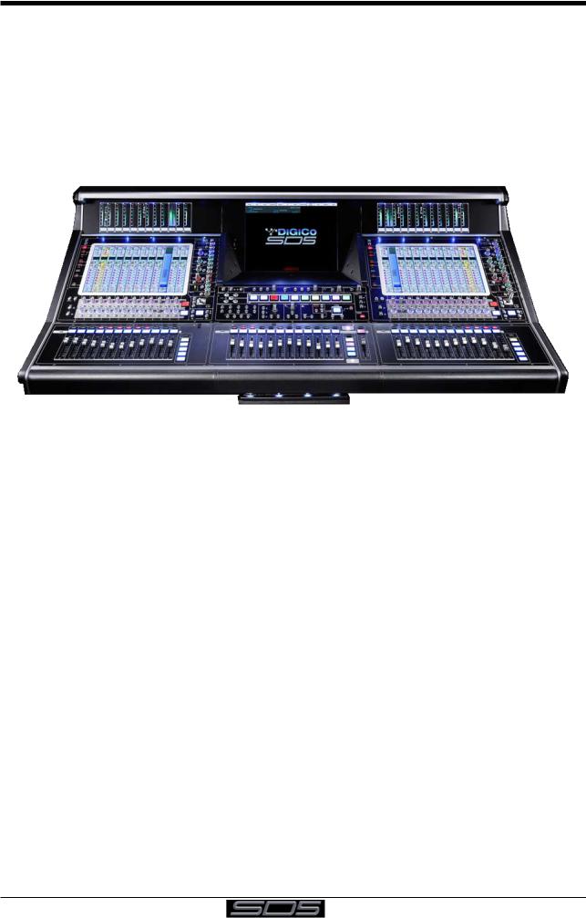
1.1 The Console
The Digico SD5 consists of a worksurface, an audio engine and a range of onboard inputs and outputs. This can be connected to multiple Input/Output Rack Units by optical fibre and/or MADI links, which carry all the audio input and output signals.
The console worksurface consists of 3 sections that can be configured to control up to 124 input channels, 24 VCAs, 56 busses plus a Master buss (Up to 5.1) and 24 Matrix Inputs and Outputs.
The left and right sections have 12 assignable faders and 12 sets of assignable on-screen channel controls, the centre section has 12 assignable faders and a master fader.
The console's buss architecture is dynamic, and can support mono, stereo, LCR, LCRS and 5.1 configurations. Multiple console setups can provide:
Front of House and Monitoring with shared stage racks and gain tracking. Remote control of one console from another console or from a laptop computer.
1.2 Manual Overview
This manual provides an overview of the desk, and describes some of the basic operating principles which the user will need to understand in order to run the desk.
For full details on all SD software functionality please refer to the SD Series Software Reference Manual available for download at www.digico.biz
The following typographical convention used in this manual: An arrow bracket (>) is used to indicate a sequence of button pressing.
For example, Layout > Fader Banks indicates that the Fader Banks button is accessed by first pressing the Layout button.
1-1

SD5 - Getting Started
1.3 Before You Start
There are certain general operating principles and terms that should be understood before continuing to use this manual. Please read this chapter carefully before proceeding.
1.3.1 Worksurface Layout ..............................................................
Left & Right Sections
|
Meter View Switch |
ALT Input Switch |
|||||||||||||||||||||||
Rotary Resolution |
|
|
|
|
|
|
|
|
|
|
|
|
|
|
|
|
|
|
|
|
|
|
|
|
High and Low Pass Filters |
|
|
|
|
|
|
|
|
|
|
|
|
|
|
|
|
|
|
|
|
|
|
|
|
||
|
|
|
|
|
|
|
|
|
|
|
|
|
|
|
|
|
|
|
|
|
|
|
|
||
|
|
|
|
|
|
|
|
|
|
|
|
|
|
|
|
|
|
|
|
|
|||||
Quick Select Switches |
|
|
|
|
|
|
|
|
|
|
|
|
|
|
|
|
|
|
|
|
|
|
|
4 Band Dynamic Parametric EQ |
|
|
|
|
|
|
|
|
|
|
|
|
|
|
|
|
|
|
|
|
|
|
|
|
|||
|
|
|
|
|
|
|
|
|
|
|
|
|
|
|
|
|
|
|
|
|
|
||||
|
|
|
|
|
|
|
|
|
|
|
|
|
|
|
|
|
|
|
|
|
|
|
|
|
Multiband Dynamics |
|
|
|
|
|
|
|
|
|
|
|
|
|
|
|
|
|
|
|
|
|
|
|
|||
|
|
|
|
|
|
|
|
|
|
|
|
|
|
|
|
|
|
|
|
|
|
|
|
|
Thresholds & On / Off |
|
|
|
|
|
|
|
|
|
|
|
|
|
|
|
|
|
|
|
|
|
|
|
|||
2nd Function & Option/All |
|
|
|
|
|
|
|
|
|
|
|
|
|
|
|
|
|
|
|
|
Joystick |
||||
|
|
|
|
|
|
|
|
|
|
|
|
|
|
|
|
|
|
|
|
|
|||||
Assignable Rotaries and Switches |
|
|
|
|
|
|
|
|
|
|
|
|
|
|
|
Channel Inserts A & B On/Off |
|||||||||
|
|
|
|
|
|
|
|
|
|
|
|
|
Direct Out On/Off |
||||||||||||
Aux / Pan / Dynamics/FX Controls |
|
|
|
|
|
|
|
|
|
|
|
|
|
||||||||||||
|
|
|
|
|
|
|
|
|
|
|
|
|
Hard Mute & Full Safe |
||||||||||||
Screen Scroll |
|
|
|
|
|
|
|
|
|
|
|
|
|
|
|
|
|
|
|
|
|
|
|||
|
|
|
|
|
|
|
|
|
|
|
|
|
|
|
|
|
|
|
|
|
Channel Scroll & Undo/Redo |
||||
|
|
|
|
|
|
|
|
|
|
|
|
|
|
|
|
|
|
|
|
|
|||||
|
|
|
|
|
|
|
|
|
|
|
|
|
|
|
|
|
|
|
|
|
|
|
|
|
|
Mute and Interactive LCD |
|
|
|
|
|
|
|
|
|
|
|
|
|
|
|
|
|
|
|||||||
|
|
|
|
|
|
|
|
|
|
|
|
|
|
|
|||||||||||
Function Button |
|
|
|
|
|
|
|
|
|
|
|
|
|
|
|
|
Layer Switch |
||||||||
|
|
|
|
|
|
|
|
|
|
|
|
|
|
|
|||||||||||
Channels Faders |
|
|
|
|
|
|
|
|
|
|
|
|
|
||||||||||||
|
|
|
|
|
|
|
|
|
|
|
|
|
|
||||||||||||
|
|
|
|
|
|
|
|
|
|
|
|
|
|
||||||||||||
|
|
|
|
|
|
|
|
|
|
|
|
|
|
|
|
|
|
|
|
|
|
|
|
|
Channel Fader Banks |
|
|
|
|
|
|
|
|
|
|
|
|
|
|
|
|
|
|
|
|
|
|
|
|
|
|
|
|
|
|
|
|
|
|
|
|
|
|
|
|
|
|
|
|
|
|
|
|
|
|
|
|
Centre Section
Screen Scroll |
Solo 1 & 2 Controls |
Phones Touch/Turn |
Rotary Resolution
Macros
Dynamic Automation
Screen Switch
Monitoring Matrix Talkback Snapshot Controls
Channel Faders/Mutes &
LCD Function Buttons Channel Fader Banks &
Assignable Master Fader
1-2

SD5 - Getting Started
1.3.2 Layers and Banks .................................................................
The SD5's worksurface is divided into Layers and Banks. Each Bank contains twelve channels, and the channels which are currently active on the control surface are defined using the fader bank and bank layer buttons to the right of the Channel Strip section’s faders:
A ‘bank’ is a set of twelve faders, and a ‘layer’ contains up to five ‘banks’. There are 2 ‘layers’ in each section of the desk, allowing up to 120 channels to be accessible on each of the left and right worksurface sections and another 96 channels in the centre section.
Pressing the bank layer button, located above the fader bank buttons, toggles between layers.
To access a bank of faders within that layer, press the appropriate fader bank button. To switch all three sections of the console to the same bank level, press and hold one of the fader bank buttons.
The specific channels which are contained within each Bank is defined in the Layout > Fader Banks display. By default, the Input channels will be assigned to Layer 1 on the left and right sections of the console. The different output channels will be assigned to Layer 2 and also to the centre section. Control Groups will be assigned to the centre section. These bank assignments can be customised by the user and saved in a session at any time. Holding any bank or layer button down for a couple of seconds will switch all 3 worksurface sections to the same bank level or layer.
1.3.3 Using the Control Surface ....................................................
There are two main ways in which all of the functions of the SD5 are accessed:
1.The touchscreen display, which can be controlled directly using a finger, or by using the keyboard and mouse
2.The physical encoders, switches and faders.
Note that when touching the screen directly, you may find it easier to use a finer point than your finger. However, in order to prevent damage to the screen, it is important that you only use devices specifically designed for touching screens (such as a pda stylus), and that you never press down hard on the screen.
A number of functions can be accessed in different ways, allowing users to operate the console using whichever interface they prefer. This manual will describe accessing on-screen functions by touching the screen directly and not by using the mouse.
All of the physical controls found in the centre section are described in full within the relevant section of the manual and many require no further introduction.
The Master screen has a row of grey buttons across the top, which are used to access a range of configuration displays. Pressing these buttons opens either a further drop-down sub-menu or a pop-up display. If a drop-down menu is opened, pressing on one of its entries will open a pop-up display. The buttons lighten to indicate that their sub-menu or pop-up display is open. A number of the buttons within each pop-up display generate further pop-ups.
Generally, buttons within the pop-ups are coloured grey when their function is inactive, switching to a colour when their function is active. Pressing on a text box opens a numeric or QWERTY keypad which can be operated directly by pressing the screen or via the console’s external keyboard.
1-3
SD5 - Getting Started
Pop-ups are closed by pressing the box in the top right-hand corner of the pop-up, marked CLOSE or CANCEL (or by pressing CAN on keypad pop-ups).
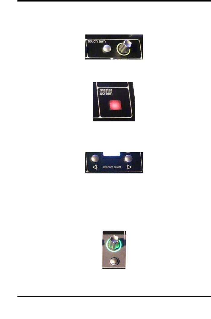
To the right of the Centre Panel is a single encoder marked Touch-Turn (shown below). This is used to access any rotary controls within the Master Screen. To assign the Touch-Turn encoder to a particular on-screen pot, touch the pot to be assigned. You will notice that a coloured ring appears around the on-screen pot, indicating that it is assigned to the Touch-Turn encoder. The colour of this ring is unique to that control, and is also reflected in the base of the Touch-Turn encoder, providing further indication of which pot is currently assigned to it.
The Master Screen button in the centre section switches the centre screen view from the Master Screen to the bank of channels which are selected in the lower centre section.
Note: When the centre screen is assigned to show channels, there are no associated rotaries and switches to control mix parameters such as EQ and Dynamics. Any controls that only involve the touch screen such as routing functions can be performed in the normal way.
1.3.4 The Assigned Channel .........................................................
One of the channels in the Channel Strip panel is displayed in gold, indicating that it is currently the Assigned Channel. This means that it has been assigned to the worksurface controls and can be configured in detail, as described below. To Assign a channel, touch anywhere in the channel on the screen (except the Aux Send area).
Alternatively, use the ch left and right buttons at the bottom of the channel worksurface controls to scroll through the channels in the panel:
Note that these left and right arrows are duplicated in the channel Setup and Output displays.
Note also that the Channel List display provides another method for assigning a channel to the worksurface controls.
Once a channel is Assigned, all of the controls for that channel which are not displayed within the channel strip itself can be accessed via secondary pop-ups, displayed by touching inside the relevant area of the channel. These pop-ups include controls such as input and output routing and signal processing parameters.
A number of the physical rotary encoders on the control surface can be assigned to different on-screen pots. In order to ensure that it is clear which function is assigned to which encoder, the assigned on-screen pot will have a coloured ring around it which will be reflected in the colour of the light around the base of the encoder on the control surface.
1-4
SD5 - Getting Started
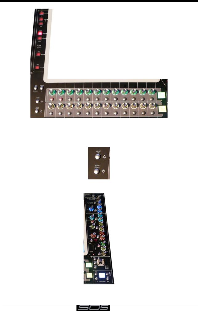
The 2 rows of twelve encoders and buttons immediately below the touchscreen (shown above) refer to the channels with which they are aligned.
Pressing one of the Quick Select buttons on the left of the screen will assign the selected function to the top row of these controls below the screen. Six aux sends can be displayed in the Channel Strip panel at any one time. If more than six aux sends have been created in the session, the scroll button outside the bottom left-hand corner of the screen can be used to scroll the display through the remaining auxiliaries.
The controls to the right of the Channel Strip panel allow the Assigned channel to be adjusted:
The top half of the channel worksurface controls (down as far as the insert a, insert b and direct buttons, as shown above) control the signal processing parameters which are displayed in the pop-ups accessed by touching in the appropriate section of the active channel. The bottom half of the channel worksurface controls is concerned with output routing.
1-5
 Loading...