


Addendum 95-8577
HART® Communication with the
X3301Multispectrum IR Flame Detector
|
|
|
|
|
|
|
|
|
|
|
|
|
|
|
|
|
|
|
|
|
|
|
|
|
|
|
|
|
|
|
|
|
|
|
|
|
|
|
|
|
|
|
|
|
|
|
|
|
|
|
|
|
|
|
|
|
|
|
|
|
|
|
|
|
|
|
|
|
|
|
|
|
|
|
|
|
|
|
|
|
|
|
|
|
|
|
|
|
|
|
|
|
|
|
|
|
|
|
|
|
|
|
|
|
|
|
|
|
|
|
|
|
|
|
|
|
|
|
|
|
|
|
|
|
|
|
|
|
|
|
|
|
|
|
|
|
|
|
|
|
|
|
|
|
|
|
|
|
|
|
|
|
|
|
|
|
|
|
|
|
|
|
|
|
|
|
|
|
|
|
|
|
|
|
|
|
|
|
|
|
|
|
|
|
|
|
|
|
|
|
|
|
|
|
|
|
|
|
|
|
|
|
|
|
|
|
|
|
|
|
|
|
|
|
|
|
|
|
|
|
|
|
|
|
|
|
|
|
|
|
|
|
|
|
|
|
|
|
|
|
|
|
|
|
|
|
|
|
|
|
|
|
|
|
|
|
|
|
|
|
|
|
|
|
|
|
|
|
|
|
|
|
|
|
|
|
|
|
|
|
|
|
|
|
|
|
|
|
|
|
|
|
|
|
|
|
|
|
|
|
|
|
|
|
|
|
|
|
|
|
|
|
|
|
|
|
|
|
|
|
|
|
|
|
|
|
|
|
|
|
|
|
|
|
|
|
|
|
|
|
|
|
|
|
|
|
|
|
|
|
|
|
|
|
|
|
|
|
|
|
|
|
|
|
|
|
|
|
|
|
|
|
|
|
|
|
|
|
|
|
|
|
|
|
|
|
|
|
|
|
|
|
|
|
|
|
|
|
|
|
|
|
|
|
|
|
|
|
|
|
|
|
|
|
|
|
|
|
|
|
|
|
|
|
|
|
|
|
|
|
|
|
|
|
|
|
|
|
|
|
|
|
|
|
|
|
|
|
|
|
|
|
|
|
|
|
|
|
|
|
3.1 |
|
|
|
|
|
|
|
Rev: 10/13 |
95-8577 |
|||||||||||||||
|
|
|
|
|
|
|
||||||||||||||||||||
Table Of Contents |
|
Interconnecting the HART Communicator with the Detector. . . . . . |
. 1 |
HART Device Description Language. . . . . . . . . . . . . . . . . . . . . . . . |
. 3 |
Detector Wiring. . . . . . . . . . . . . . . . . . . . . . . . . . . . . . . . . . . . . . . . |
. . 3 |
HART Menu Structure.. . . . . . . . . . . . . . . . . . . . . . . . . . . . . . . . . . . |
. 4 |
X3301 Root Menu.. . . . . . . . . . . . . . . . . . . . . . . . . . . . . . . . . . . . . . |
. 5 |
Device Info Menu. . . . . . . . . . . . . . . . . . . . . . . . . . . . . . . . . . . . . . . |
. 5 |
General Info Menu. . . . . . . . . . . . . . . . . . . . . . . . . . . . . . . . . . . . . . |
. 6 |
HART Info Menu. . . . . . . . . . . . . . . . . . . . . . . . . . . . . . . . . . . . . . . |
. . 7 |
HART PV Menu. . . . . . . . . . . . . . . . . . . . . . . . . . . . . . . . . . . . . . . . |
. 8 |
Condensed Status. . . . . . . . . . . . . . . . . . . . . . . . . . . . . . . . . . . . . . |
. 9 |
Status Info Menu.. . . . . . . . . . . . . . . . . . . . . . . . . . . . . . . . . . . . . . |
. 10 |
Hardware Menu. . . . . . . . . . . . . . . . . . . . . . . . . . . . . . . . . . . . . . . . |
11 |
oi Menu. . . . . . . . . . . . . . . . . . . . . . . . . . . . . . . . . . . . . . . . . . . . . |
. 12 |
Detector Settings. . . . . . . . . . . . . . . . . . . . . . . . . . . . . . . . . . . . . . |
. 13 |
History Menu.. . . . . . . . . . . . . . . . . . . . . . . . . . . . . . . . . . . . . . . . . |
. 13 |
Command Menu. . . . . . . . . . . . . . . . . . . . . . . . . . . . . . . . . . . . . . . |
. 14 |
HART CMD Menu. . . . . . . . . . . . . . . . . . . . . . . . . . . . . . . . . . . . . . |
. 15 |
Device Setup Menu.. . . . . . . . . . . . . . . . . . . . . . . . . . . . . . . . . . . . |
. 15 |
Configuration Menu.. . . . . . . . . . . . . . . . . . . . . . . . . . . . . . . . . . . . |
. 16 |
Calibration Menu.. . . . . . . . . . . . . . . . . . . . . . . . . . . . . . . . . . . . . . |
. 16 |
Write Protect. . . . . . . . . . . . . . . . . . . . . . . . . . . . . . . . . . . . . . . . . . |
. 17 |
HART Setup . . . . . . . . . . . . . . . . . . . . . . . . . . . . . . . . . . . . . . . . . . |
. 17 |
Set Real Time Clock. . . . . . . . . . . . . . . . . . . . . . . . . . . . . . . . . . . . |
. 18 |

ADDENDUM
HART Communication
with the X3301
Multispectrum IR Flame Detector
Digital communication with the X3301 allows the operator to monitor the status of the detector, determine factory settings, adjust field settings, and initiate field tests. This addendum provides guidance for establishing HART communication, and describes the HART menu structure when using the X3301 with a HART Handheld Communicator, a PC, or other process interface device that supports DDL.
NOTE
A minimum level of understanding with regard to the operation and navigation of the HART Communicator is required. Refer to the instruction manual supplied with the HART Communicator for basic operating instructions.
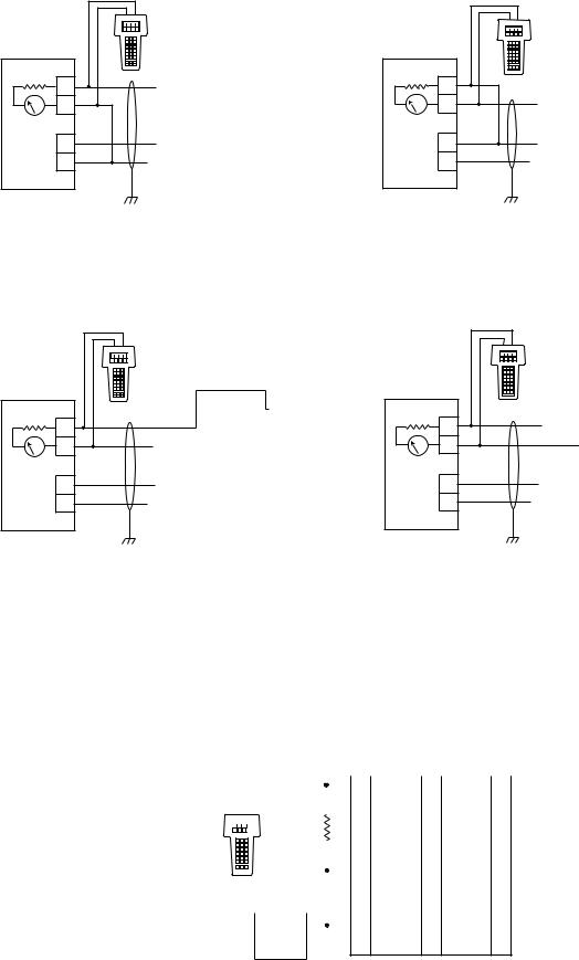
INTERCONNECTING THE HART COMMUNICATOR WITH THE DETECTOR
Point-to-Point Mode
The HART Communicator can connect to the X3301 at any wiring termination point in the analog output signal loop. Connect the HART communicator in parallel with the X3301 analog signal or load resistor. The HART connections are non-polarized.
IMPORTANT WIRING NOTE
The HART Communicator does not measure loop current directly, but instead reads a voltage signal across a resistance (250 ohms) in the loop. The recommended connection point is across the input impedance of the signal receiver (PLC), which is a nominal 250 ohms. See Figures 1 to 4. If testing/ programming on a bench, a 250 ohm load resistor must be used. See Figure 5.
Switch on the HART Communicator. If a device is found, the HART Communicator displays the Main menu. If no device is found, check the connections and verify the presence of a minimum of 250 ohms load resistance in series in the loop.
3..1 |
©Detector Electronics Corporation 2013 |
Rev: 10/13 |
95-8577 |
|
PLC |
600 Ω MAX* |
|
AT |
24 VDC |
|
+ |
|
– |
|
mA |
|
+ |
|
24 VDC |
|
– |
|
B2262 |
X3301 IR DETECTOR
|
|
|
|
|
|
|
|
|
|
|
|
9 |
mA + |
|
19 |
mA – |
29 |
|
|
|
|
|||||
|
|
|
|
|
|
|
|
|
|
|
|
8 |
mA + REF |
18 |
|
28 |
|
|
|
|
|
|||||
|
|
|
|
|
|
|
|
|
|
|
|
7 |
|
|
17 |
|
27 |
|
|
|
|
|
|
|
|
|
|
|
|
6 |
|
|
16 |
|
26 |
|
|
|
|
|
|
|
|
|
|
|
|
5 |
|
|
15 |
|
25 |
|
|
|
|
|
|
|
|
|
|
|
|
4 |
|
|
14 |
|
24 |
|
|
|
3 |
|
|
13 |
|
23 |
|
|
|
|
24 VDC + |
|
|
|
|
|
|
|
2 |
12 |
|
22 |
||
|
|
|
|
|||||
|
|
|
|
|
|
|
|
|
|
|
|
1 |
24 VDC – |
11 |
|
21 |
|
|
|
|
|
|||||
|
|
|
|
|
|
|
|
|
Figure 1—X3301 Detector Wired for Non-Isolated 0 to 20 mA Current Output (Sourcing)
|
PLC |
600 Ω MAX* |
|
AT |
24 VDC |
|
+ |
|
– |
|
mA |
|
+ |
|
24 VDC |
|
– |
|
B2264 |
24 VDC |
|
X3301 IR DETECTOR |
|
|||||||
– |
+ |
|
|
|
|
|||||
|
|
|
|
|
|
|
||||
|
|
|
|
|
|
|
|
|
|
|
|
|
|
|
|
|
9 |
mA + |
19 |
mA – |
29 |
|
|
|
|
|
|
|||||
|
|
|
|
|
|
|
|
|
|
|
|
|
|
|
|
8 |
|
18 |
|
28 |
|
|
|
|
|
|
|
|
|
|
|
|
|
|
|
|
|
|
7 |
|
17 |
|
27 |
|
|
|
|
|
|
|
|
|||
|
|
|
|
|
|
|
|
|
|
|
|
|
|
|
|
|
6 |
|
16 |
|
26 |
|
|
|
|
|
|
|
|
|
|
|
|
|
|
|
|
|
5 |
|
15 |
|
25 |
|
|
|
|
|
|
|
|
|
|
|
|
|
|
|
|
|
4 |
|
14 |
|
24 |
|
|
|
|
|
|
3 |
|
13 |
|
23 |
|
|
|
|
|
|
|
|
|
|
|
|
|
|
|
|
|
2 |
24 VDC + |
12 |
|
22 |
|
|
|
|
|
|
|
||||
|
|
|
|
|
|
24 VDC – |
|
|
|
|
|
|
|
|
|
|
1 |
11 |
|
21 |
|
|
|
|
|
|
|
|
||||
|
|
|
|
|
|
|
|
|
|
|
Figure 2—X3301 Detector Wired for Isolated 0 to 20 mA Current Output (Sourcing)
|
PLC |
600 Ω MAX* |
|
AT |
24 VDC |
|
+ |
|
– |
|
mA |
|
+ |
|
24 VDC |
|
– |
|
B2263 |
X3301 IR DETECTOR
|
|
9 |
mA + |
|
19 |
mA – |
29 |
|
|
8 |
|
|
18 |
mA – REF |
28 |
|
|
|
|
||||
|
|
|
|
|
|
|
|
|
|
7 |
|
|
17 |
|
27 |
|
|
|
|
|
|||
|
|
|
|
|
|
|
|
|
|
6 |
|
|
16 |
|
26 |
|
|
|
|
|
|
|
|
|
|
5 |
|
|
15 |
|
25 |
|
|
|
|
|
|
|
|
|
|
4 |
|
|
14 |
|
24 |
|
|
3 |
|
|
13 |
|
23 |
|
|
|
24 VDC + |
|
|
|
|
|
|
2 |
12 |
|
22 |
||
|
|
|
|||||
|
|
|
|
|
|
|
|
|
|
1 |
24 VDC – |
11 |
|
21 |
|
|
|
|
|||||
|
|
|
|
|
|
|
|
Figure 3—X3301 Detector Wired for Non-Isolated 0 to 20 mA Current Output (Sinking)
|
PLC |
600 Ω MAX* |
|
AT |
24 VDC |
|
+ |
|
– |
|
mA |
|
+ |
|
24 VDC |
|
– |
|
B2265 |
|
24 VDC |
|
|
|
|
|
|
|
|||||
|
+ |
– |
|
|
X3301 IR DETECTOR |
|
|||||||
|
|
|
|
|
|
|
|
|
|
|
|
|
|
|
|
|
|
|
|
|
|
9 |
mA + |
|
19 |
mA – |
29 |
|
|
|
|
|
|
|
|
8 |
|
|
18 |
|
28 |
|
|
|
|
|
|
|
|
|
|
|
|||
|
|
|
|
|
|
|
|
|
|
|
|
|
|
|
|
|
|
|
|
|
|
7 |
|
|
17 |
|
27 |
|
|
|
|
|
|
|
|
|
|
|
|||
|
|
|
|
|
|
|
|
|
|
|
|
|
|
|
|
|
|
|
|
|
|
6 |
|
|
16 |
|
26 |
|
|
|
|
|
|
|
|
|
|
|
|
|
|
|
|
|
|
|
|
|
|
5 |
|
|
15 |
|
25 |
|
|
|
|
|
|
|
|
|
|
|
|
|
|
|
|
|
|
|
|
|
|
4 |
|
|
14 |
|
24 |
|
|
|
|
|
|
|
|
3 |
|
|
13 |
|
23 |
|
|
|
|
|
|
|
|
|
24 VDC + |
|
|
|
|
|
|
|
|
|
|
|
|
2 |
12 |
|
22 |
||
|
|
|
|
|
|
|
|
|
|||||
|
|
|
|
|
|
|
|
|
|
|
|
|
|
|
|
|
|
|
|
|
|
1 |
24 VDC – |
11 |
|
21 |
|
|
|
|
|
|
|
|
|
|
|||||
|
|
|
|
|
|
|
|
|
|
|
|
|
|
Figure 4—X3301 Detector Wired for Isolated 0 to 20 mA Current Output (Sinking)
*Nominal input impedance of PLC = 250 ohms.
Maximum loop impedance including input impedance of PLC = 600 ohms.
|
|
|
|
|
|
|
|
|
|
X3301 IR DETECTOR |
|
||||
|
|
|
|
|
|
|
|
|
|
|
|
|
|
|
|
|
|
|
|
|
|
|
|
|
9 |
mA + |
|
|
19 |
mA – |
29 |
|
|
|
|
|
|
|
|
|
|
|
|||||
|
|
|
|
|
|
|
|
|
|
|
|
|
|
mA – REF |
|
|
|
|
|
|
|
|
|
8 |
|
|
|
18 |
28 |
||
|
|
|
|
|
|
|
|
|
|
|
|||||
|
|
|
|
|
|
|
|
|
|
|
|||||
|
|
|
|
250 Ω |
7 |
|
|
17 |
|
27 |
|||||
|
|
|
|
|
|
|
|||||||||
|
|
|
|
|
|
|
|
|
|
|
|
|
|
|
|
|
|
|
|
|
|
|
|
6 |
|
|
16 |
|
26 |
||
|
|
|
|
|
|
|
|
|
|
|
|||||
|
|
|
|
|
|
|
|
|
|
|
|
|
|
|
|
|
|
|
|
|
|
|
|
5 |
|
|
15 |
|
25 |
||
|
|
|
|
|
|
|
|
|
|
|
|
|
|
|
|
|
|
|
|
|
|
|
|
4 |
|
|
14 |
|
24 |
||
|
|
|
|
|
|
|
|
|
|
|
|
|
|
|
|
|
|
|
|
|
|
|
|
3 |
|
|
13 |
|
23 |
||
|
|
|
|
|
|
|
|
|
|
|
|
|
|
|
|
|
+ |
|
|
|
|
|
24 VDC + |
|
|
|
|
||||
|
|
|
|
|
2 |
12 |
|
22 |
|||||||
|
|
|
|
|
|
||||||||||
|
|
|
24 VDC |
|
|
|
|
|
|
|
|
||||
|
|
1 |
24 VDC – |
11 |
|
21 |
|||||||||
|
|
|
|
– |
|
|
|
|
|
||||||
|
|
|
|
|
|
||||||||||
B2261
Figure 5—Wiring the X3301 for Benchtop Testing/Programming Using HART Protocol
3.1 |
2 |
95-8577 |
Multidrop Mode
Optical flame detectors are life safety devices and require the 4-20 mA loop for transmitting important detector status data. They should not be used in conjunction with multidrop mode. If multidrop mode is a requirement, the alarm and fault relay contacts must be connected directly to the safety system or fire panel for signalling purposes.
NOTE
This addendum covers HART wiring only. Refer to the device instruction manual for NFPA-72 compliant releasing wiring diagrams.
HART DEVICE DESCRIPTION LANGUAGE
The HART protocol incorporates a concept called the Device Description Language (DDL) that enables all suppliers of HART instruments to define and document their products in a single consistent format. This format is readable by handheld communicators, PCs and other process interface devices that support DDL. DDL enables full interoperability of devices, regardless of manufacturer, allowing full functionality from any HART device.
In the event that your Communicator does not establish communications with the X3301, ensure that the appropriate DDLs for the X3301 have been programmed into your Communicator. To review the DDLs programmed into your HART Communicator:
1.From the Main menu, access the Offline menu.
2.From the Offline menu, select New Configuration to access the list of device descriptions programmed into the HART Communicator.
3.Select Det-Tronics and review the list of models to determine if the X3301 DDLs are installed in your Communicator.
If the X3301 DDLs have not been programmed into the Memory Module, you must use the generic interface built into your HART Communicator.
The HART Communication Foundation manages a library of Manufacturer Device Descriptions, which are distributed to programming sites for inclusion in master devices. A complete listing of the HCF DD Library is available for download in manufacturer and device type sequence at http://www.hartcommproduct.com/.
DETECTOR WIRING
Refer to the X3301 instruction manual (form number 95-8527) for complete instructions regarding detector installation and wiring. However, note that the device power consumption specifications for the HART model are different than the standard model.
Power Consumption Specifications of X3301 Detector with HART Communication
Without heater: 4.7 watts at 24 Vdc nominal;
6.1watts at 24 Vdc in alarm.
5.5watts at 30 Vdc nominal;
7.4watts at 30 Vdc in alarm.
Heater only: 8 watts maximum.
Total power: 17 watts at 30 Vdc with EOL resistor installed and heater on maximum.
EOL resistor must be ceramic, wirewound type, rated 5 watts minimum, with actual power dissipation not to exceed 1.5 watts.
3.1 |
3 |
95-8577 |

HART MENU STRUCTURE
X3301 Root Menu |
|
Device Info Menu |
|||
1) |
Fire |
(Yes/No) |
1) |
General Info Menu |
|
2) |
Fault |
(Yes/No) |
2) |
HART Info Menu |
|
3) |
Device Info Menu |
|
3) |
Status Info Menu |
|
4) |
Command Menu |
4) |
Detector Settings |
||
5) |
Device Setup Menu |
5) |
History Menu |
||
Command Menu
1) Start Passive oi
2) Start Active oi
3) Clear oi Fault
4) Reset Latches
5) Master Reset
6) Clear Data Log
7) HART Command Menu
HART Command Menu
1) |
Self Test |
2) |
Master Reset |
3) |
Loop Test |
Device Setup Menu
1) Configuration Menu
2) Calibration Menu
3) Write Protect
4) HART Setup
5) Set Real Time Clock
General Info Menu |
|
|
|
|
HART PV Menu |
|||
1) |
Manufacturer |
1) |
PV Unit |
|||||
2) |
Model |
|
2) |
PV |
||||
3) |
Serial Number |
3) |
PV SNSR Unit |
|||||
4) |
Part Number |
4) |
PV USL |
|||||
5) |
Manufactured Date |
5) |
PV LSL |
|||||
6) |
Snsr Fmwr Ver |
6) |
PV MIN SPAN |
|||||
7) |
HART Fmwr Ver |
|
|
7) |
PV DAMP |
|||
8) |
Real Time Clock |
|
8) |
PV AO |
||||
9) |
Write Protect (Y/N) |
|
9) |
PV AO ALRM TYP |
||||
|
|
|
|
|
|
|
10) PV % RNGE |
|
HART Info Menu |
|
|
|
|
11) PV XFER FNCTN |
|||
|
|
|
|
12) PV RNGE Unit |
||||
1) |
Universal Rev |
|
|
|
|
|||
|
|
|
|
13) PV URV |
||||
2) |
Field Device Rev |
|
|
|
|
|||
|
|
|
|
14) PV LRV |
||||
3) |
Final Asmbly No. |
|
|
|
|
|||
|
|
|
|
15) PV SNSR S/N |
||||
4) |
Tag |
|
|
|
|
|
||
|
|
|
|
|
|
|
||
5) |
Date |
|
|
|
|
|
Condensed Status |
|
6) |
Descriptor |
|
|
|
|
|||
7) |
Message |
|
|
1) |
Xmtr Addstatus 0 |
|||
8) |
Num Req Preams |
|
2) |
Xmtr Addstatus 1 |
||||
9) |
HART PV Menu |
|
|
3) |
Xmtr Addstatus 2 |
|||
|
|
|||||||
10) Condensed Status |
4) |
Xmtr Addstatus 3 |
||||||
|
|
|
5) |
Operating Mode |
||||
Status Info Menu |
6) |
Operating Mode 2 |
||||||
|
|
|
|
|
|
|||
1) Warmup (Y/N) |
|
|
|
|
|
|
||
2) |
Fire (Y/N) |
|
|
|
|
|
|
|
3) Auto oi Fault (Y/N) |
|
|
|
|
Hardware Menu |
|||
4) |
Dim Detect Fault (Y/N) |
|
|
|
|
|||
5) |
Detect Disable Flt (Y/N) |
1) |
Heater Power |
|||||
6) |
Snsr Hdwr Fault (Y/N) |
2) |
Heater Setpoint |
|||||
7) HIB Hdwr Fault (Y/N) |
3) |
Temperature |
||||||
8) Int Comm Fault |
|
|
|
4) |
Temp Setpoint |
|||
9) Incompatible Flt |
|
5) |
Temp Range Fault |
|||||
10) Voltage Fault (Y/N) |
|
6) |
Voltage |
|||||
11) Hardware Menu |
|
7) |
Volt Range Fault |
|||||
12) oi Menu |
|
|
|
|
|
|
|
|
|
|
|
|
|
|
|
oi Menu |
|
Detector Settings |
|
1) |
Left oi |
|||||
1) |
Fire Relay |
(L/NL) |
|
2) |
Middle oi |
|||
2) |
Fire Relay |
(NDE/NE) |
|
3) |
Right oi |
|||
3) |
Fault Relay |
(L/NL) |
|
|
|
|
4) |
Cons oi Fails |
4) |
Fault Relay |
(NDE/NE) |
5) |
No. oi Failures |
||||
5) Aux Relay |
(L/NL) |
6) |
oi Cal Active |
|||||
6) Aux Relay (NDE/NE) |
7) |
oi Cal Fault |
||||||
7) |
Sensitivity |
(VH/H/M/L) |
8) |
Manual oi Active |
||||
8) |
Response |
(.5/3/6/9) |
9) |
Manual oi Fail |
||||
History Menu
1)Alarm Log
2)Fault Log
3)General Log
Configuration Menu
1)Edit Cons oi Fails
2)Edit Temp Setpoint
3)Edit Heater Setpoint
Calibration Menu
1)Loop Test
2)D/A Trim
3)Calibrate oi
Write Protect
1)Set Password
2)Set Write Protect
3)Write Protect (Y/N)
HART Setup
1)Polling Address
2)Final Asmbly No.
3)Tag
4)Date
5)Descriptor
6)Message
Set Real Time Clock
1)Seconds
2)Minutes
3)Hours
4)Date
5)Month
6)Year
3.1 |
4 |
95-8577 |

X3301 ROOT MENU
When HART communication is established, the first menu displayed is the X3301 Root menu:
X3301 Root Menu
1)Fire (Yes/No)
2)Fault (Yes/No)
3)Device Info Menu
4)Command Menu
5)Device Setup Menu
1) |
Fire (Yes/No) |
Indicates “Y” if the device is in a fire alarm status — analog output is at 20 mA, fire alarm |
|
|
relay is actuated and LED is red. |
2) |
Fault (Yes/No) |
Indicates “Y” if a fault condition exists. Go to “Device Info” and select “Status Info” to |
|
|
determine the nature of the fault. |
3) |
Device Info Menu |
Provides access to manufacturer and HART information, current device status, factory |
|
|
settings, and history logs. |
4) Command Menu |
This menu allows the operator to initiate a manual oi test and also to perform various reset/ |
|
|
|
clear functions. |
5) |
Device Setup Menu |
This menu allows various setup, configuration and calibration functions. |
DEVICE INFO MENU
This menu allows access to a variety of “read only” information.
X3301 Root Menu |
|
Device Info Menu |
||||
1) |
Fire |
(Yes/No) |
1) |
General Info Menu |
||
2) |
Fault |
(Yes/No) |
|
|
2) |
HART Info Menu |
3) |
Device Info Menu |
|
3) |
Status Info Menu |
||
4) |
Command Menu |
4) |
Detector Settings |
|||
5) |
Device Setup Menu |
5) |
History Menu |
|||
1) General Info Menu |
Factory information. |
2) HART Info Menu |
HART Specific Variables. |
3)Status Info Menu Current operating status and/or diagnostic information.
4)Detector Settings Factory settings relating to relay operation, detector sensitivity and response.
5) History Menu |
Display log files: Alarm, Fault, General. |
3.1 |
5 |
95-8577 |
 Loading...