


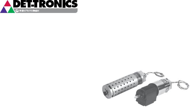
Instructions
PointWatchTM Infrared Hydrocarbon Gas Detector
Model PIR9400
|
|
|
9.3 |
Rev: 11/12 |
95-8440 |
Table Of Contents
APPLICATION. . . . . . . . . . . . . . . . . . . . . . . 1
FEATURES. . . . . . . . . . . . . . . . . . . . . . . . 1
SPECIFICATIONS. . . . . . . . . . . . . . . . . . . . . . 2
DESCRIPTION . . . . . . . . . . . . . . . . . . . . . . . 5 Detection Method. . . . . . . . . . . . . . . . . . . . 5 Current Loop Output. . . . . . . . . . . . . . . . . . . 5 Operating Modes . . . . . . . . . . . . . . . . . . . . 5
INSTALLATION. . . . . . . . . . . . . . . . . . . . . . . 6 Detector Location. . . . . . . . . . . . . . . . . . . . 6 0 to 100% LFL Linearized Output Options. . . . . . . . . . . 7 PointWatch Termination Boxes (PIRTB). . . . . . . . . . . 10 General Wiring Requirements . . . . . . . . . . . . . . . 10 Detector Wiring Procedure. . . . . . . . . . . . . . . . 11 Detector Separation (Optional). . . . . . . . . . . . . . . 13
STARTUP PROCEDURE . . . . . . . . . . . . . . . . . . 14 |
|
CALIBRATION . . . . . . . . . . . . . . . . . . . . . . |
15 |
Calibration Equipment. . . . . . . . . . . . . . . . . |
15 |
Calibration Procedures . . . . . . . . . . . . . . . . . |
15 |
MAINTENANCE . . . . . . . . . . . . . . . . . . . . . . 19 Disassembly and Cleaning Procedure. . . . . . . . . . . . 20
TROUBLESHOOTING . . . . . . . . . . . . . . . . . . . 22
Replacement Parts.. . . . . . . . . . . . . . . . . . 22
DEVICE REPAIR AND RETURN . . . . . . . . . . . . . . . 22
ORDERING INFORMATION. . . . . . . . . . . . . . . . . 24
APPENDIX A – FM APPROVAL . . . . . . . . . . . . . . . . 26
APPENDIX B – CSA APPROVAL. . . . . . . . . . . . . . . 27
APPENDIX C – ATEX / CE APPROVAL. . . . . . . . . . . . . 28
APPENDIX D – IECEx APPROVAL . . . . . . . . . . . . . . |
30 |
APPENDIX E – ADDITIONAL APPROVALS. . . . . . . . . . . 31
INSTRUCTIONS
PointWatchTM Infrared
Hydrocarbon Gas Detector
Model PIR9400
 Caution
Be sure to read and understand the entire instruction manual before installing or operating the gas detection system. This product is intended to provide early warning of the presence of a flammable or explosive gas mixture. Proper device installation, operation, and maintenance is required to ensure safe and effective operation. If this equipment is used in a manner not specified in this manual, safety protection may be impaired.
APPLICATION
The PointWatchTM Infrared Gas Detector Model PIR9400 is a diffusion-based point-type infrared gas detector. The PointWatch Detector is approved to provide continuous monitoring of methane gas concentration in the range of 0 to 100% LFL. The detector provides a 4-20 mA output signal, corresponding to the detected gas concentration. It has Division and Zone explosion-proof ratings and is suitable for use in indoor and outdoor applications.
The PointWatch Detector Model PIR9400 is ideally suited for use in harsh environments and where the cost of required maintenance for conventional catalytic detectors is prohibitive. It will perform reliably in the presence of silicone and other catalytic poisoning agents and can also operate in oxygen free environments or where high background gas levels are present. There are no known poisons that affect this technology.
The PointWatch Detector is globally certified for use in Class 1, Divisions 1 and 2, and Zone 1 hazardous areas. It is also approved as a stand alone gas detector, and complies with global approvals when connected to a stand-alone approved controller for life safety. The approved Det-Tronics controllers are the FlexVu® UD10, Infiniti® U9500, R8471, and Eagle Quantum Premier® (EQP).
FEATURES
•Compliance to ANSI/ISA 12.13.01-2000 performance standard.
•Requires no routine calibration to ensure proper operation.
•Fail-safe operation.
•Continuous self-test automatically indicates a fault or fouled optics condition.
•Unique multi-layered filtering system protects optics from dirt and water ingress.
•Internal heating system minimizes condensation, allowing reliable operation through temperature extremes.
•There are no known poisons, e.g. silicones or hydrides, that compromise the integrity of the measurement.
•Performs well in the presence of high concentrations or constant background levels of hydrocarbons, and in oxygen depleted atmospheres.
•Standard 4–20 mA output (current source).
•Compact, lightweight, explosion-proof housing is designed for duty in harsh environments.
•Standard 0 to 100% LFL detection range.
9.3 |
©Detector Electronics Corporation 2012 |
1 |
Rev: 11/12 |
95-8440 |

SPECIFICATIONS
PointWatch Gas Detector (PIR9400)
INPUT VOLTAGE—
24 Vdc nominal. Operating range is 18 to 30 Vdc.
POWER CONSUMPTION (Watts)— |
|
||
Input Voltage: |
18 Vdc |
24 Vdc |
30 Vdc |
Nominal |
3.5 |
4.6 |
6.2 |
Maximum |
4.0 |
5.5 |
7.0 |
DETECTION RANGE—
0 to 100% LFL.
GASES —
The Model PIR9400 Detector is approved to Methane, but most flammable hydrocarbon vapors (ethane, ethylene, propane, butane, and propylene) are also detectable.
Methane gas detection is the factory default gas type setting. Reference the “IR Module Removal and Gas Selection” section of this manual for alternate gas type settings.
CURRENT OUTPUT (NON-ISOLATED)—
Linear 0–20 mA current source.
•4–20 mA output indicates 0 to 100% LFL detection range (for linearized gases)
•23.2 mA indicates over-range condition
•0–2.4 mA levels indicate calibration, fault and fouled optics conditions.
Refer to Table 1 for a detailed description of current outputs.
Maximum loop |
resistance: 580 ohms at 24 Vdc. |
|
See Figure 1 for further information. |
||
Table 1—Current Loop Output Levels and Corresponding Status |
||
|
Indications |
|
|
|
|
Current Level |
Status |
|
23.2 mA |
Over-range |
|
20.0 mA |
Full scale (100% LFL) |
|
4.0 mA |
Zero gas level (0% LFL) |
|
2.2 mA |
Zero calibration in progress |
|
2.0 mA |
Span calibration in progress |
|
1.8 mA |
Calibration complete - remove gas |
|
1.6 mA |
Calibration fault |
|
1.0 mA |
Fouled optics |
|
0.8 mA |
24 Vdc line low (less than 17.5 Vdc) |
|
0.6 mA |
Calibrate input active at power-up |
|
(probable wiring fault) |
|
|
|
|
|
0.4 mA |
Active channel fault |
|
0.2 mA |
Reference channel fault |
|
0.0 mA |
CPU system fault, warmup |
|
|
|
|
NOTE
The following specifications for Accuracy, Stability and Repeatability are based on 0 to 100% LFL methane.
ACCURACY (Room Temperature)—
±3% LFL from 0 to 50% LFL, ±5% LFL from 51% to
100% LFL.
RESPONSE TIME (seconds)— |
|
|
|
Multilayered aluminum weather baffle |
N·m |
T90 |
|
7 |
14.4 |
||
With hydrophobic filter |
|||
Without hydrophobic filter |
5 |
10 |
|
Polyphthalamide (PPA) weather baffle |
6 |
16 |
|
With hydrophobic filter |
|||
Without hydrophobic filter |
2 |
3 |
STABILITY—
Temperature
Zero: ±2% LFL from
–40°F to +167°F (–40°C to +75°C)
Span: ±5% LFL at 50% LFL from
–13°F to +167°F (–25°C to +75°C)
±10% LFL at 50% LFL from
–40°F to –13°F (–40°C to –25°C). Time (10 months) ±2% LFL (Det-Tronics verified).
REPEATABILITY (Room Temperature)—
Zero: ±1% LFL
Span: ±2% LFL at 50% LFL (Det-Tronics verified).
(OHMS) |
900 |
|
|
|
|
|
|
|
|
|
|
|
|
|
|
|
|
|
|
|
|
|
|
|
|
|
|
|
|
|
|
||||
800 |
|
|
|
|
|
|
|
|
|
|
|
|
|
|
|
|
|
|
|
|
|
|
|
|
|
|
|
|
|
|
|
|
|
||
RESISTANCE |
|
|
|
|
|
|
|
|
|
|
|
|
|
|
|
|
|
700 |
|
|
|
|
|
|
|
|
|
|
|
|
|
|
|
|
|
|
|
|
|
|
|
|
|
|
|
|
|
|
|
|
|
||
LOOP |
|
|
|
|
|
|
|
|
|
|
|
|
|
|
|
|
|
600 |
|
|
|
|
|
|
|
|
|
|
|
|
|
|
|
|
|
|
|
|
|
|
|
|
|
|
|
|
|
|
|
|
|
||
MAXIMUM |
|
|
|
|
|
|
|
|
|
|
|
|
|
|
|
|
|
500 |
|
|
|
|
|
|
|
|
|
|
|
|
|
|
|
|
|
|
|
|
|
|
|
|
|
|
|
|
|
|
|
|
|
||
|
|
|
|
|
|
|
|
|
|
|
|
|
|
|
|
|
|
|
|
|
|
|
|
|
|
|
|
|
|
|
|
|
|
|
|
|
40018 |
|
|
|
|
|
|
|
|
|
|
|
|
|
|
||
|
20 |
22 |
24 |
26 |
28 |
30 |
32 |
||||||||||
|
|
|
|
|
|
POWER SUPPLY VOLTAGE (VDC) |
|
|
|
|
|||||||
C1964 |
LOOP RESISTANCE (OHMS) |
|
Figure 1—4 to 20 mA Current Loop Resistance
9.3 |
2 |
95-8440 |
WIRING—
The PointWatch Detector has five 22 AWG wires, 20 inches long for wiring into a termination box, FlexVu UD10 or the Infiniti U9500.
Red |
= |
+ 24 Vdc |
Black |
= |
– (common) |
White |
= |
4–20 mA signal output |
Yellow |
= |
Calibration input |
Green |
= |
Chassis ground |
Power Wiring: 18 AWG minimum is recommended for power wiring. Larger diameter wire may be required to maintain a minimum of 18 Vdc (including ripple) at the sensor for all operating conditions (see Figure 2). For maximum EMI/RFI protection, shielded cable is recommended.
IN FEET |
2500 |
|
|
|
|
|
|
|
POINTWATCHTO |
|
|
|
|
|
|
|
|
2000 |
|
|
|
|
|
|
|
|
|
|
|
|
|
|
|
|
|
SUPPLY |
1500 |
|
|
|
|
|
|
|
POWERFROM |
1000 |
|
|
|
|
|
|
|
|
|
|
|
|
|
|
|
|
DISTANCE |
500 |
|
|
|
|
|
|
|
018 |
|
|
|
|
|
|
C1962 |
|
|
|
|
|
|
|
|
||
MAXIMUM |
20 |
22 |
24 |
26 |
28 |
30 |
32 |
|
|
|
POWER SUPPLY VOLTAGE (VDC) |
|
|
||||
|
|
|
|
|
||||
|
|
12 AWG |
|
14 AWG |
|
16 AWG |
|
18 AWG |
Figure 2—PIR9400 Wiring Requirements
OPERATING TEMPERATURE RANGE—
–40°C to +75°C (–40°F to +167°F).
STORAGE TEMPERATURE RANGE—
–55°C to +85°C (–67°F to +185°F).
HUMIDITY (non-condensing)—
0 to 99% relative humidity (Det-Tronics verified)
5 to 95% relative humidity (FM/CSA verified).
RFI/EMI PROTECTION—
Operates properly with 5 watt walkie-talkie keyed at 1 meter.
INGRESS PROTECTION—
IP66.
ENCLOSURE MATERIALS—
Aluminum (clear anodized) enclosure and weather protection baffles. Content: 0.8% to 1.2% Mg, 0.15% to 0.40% CU.
Stainless Steel (316 electropolished) enclosure, polyphthalamide (PPA) weather protection baffle.
DIMENSIONS—
See Figures 3 and 4 for the dimensions of the PointWatch Detector.
WARNING
Always ensure that the detector/termination box hazardous (classified) location ratings are applicable for the intended use.
PointWatch Termination Box (PIRTB)
INPUT VOLTAGE—
24 Vdc nominal. Operating range is 18 to 30 Vdc.
POWER CONSUMPTION (Watts)—
0.5 Watts Maximum
MOUNTING—
The Det-Tronics Termination Box, Model PIRTB, is recommended for optimum ease of installation and calibration of the PointWatch Detector. Depending on the specific application, the detector can be threaded into any Det-Tronics approved termination box. (Termination box spacers may be required for flush mounting. The PIRTB, FlexVu UD10, and Infiniti U9500 come standard with M25 threads, and may require a reducer when used with the PointWatch Detector).
PointWatch Detector thread options:
•3/4 inch NPT
•M20
SHIPPING WEIGHT (PIRTB)—
Aluminum Tall Box: |
2.2 lbs (1.0 kg) |
Aluminum Short Box: |
2.0 lbs (0.95 kg) |
Stainless Steel Tall Box: |
9.5 lbs (4.3 kg) |
Stainless Steel Short Box: 9.0 lbs (4.1 kg).
DIMENSIONS—
See Figure 5 for dimensions of the PIRTB.
TERMINALS—
PIRTB terminals UL/CSA rated for 14 to 22 AWG wire; terminals DIN/VDE rated for 2.5 mm2 wire.
9.3 |
3 |
95-8440 |

CERTIFICATION—
FM |
® |
APPROVED |
|
For complete approval details for the PointWatch Detector Model PIR9400 and the PointWatch Termination Box Model PIRTB, refer to the appropriate Appendix:
Appendix A - FM
Appendix B - CSA
Appendix C - ATEX/CE
Appendix D - IECEx
Appendix E - Additional approvals
4.7
(11.9)
3.46
(8.8)
5.86
(14.9)
5.2
(13.2)
2.7
(6.9)
9.45
(24.0)
2.5
(6.4)
C1752 |
|
|
|
3/4 – NPT |
|
|
|
|
M20 X 1.5 |
Figure 3—Aluminum PIR9400 Dimensions in Inches (cm)
6.57
(16.7)
1.28
(3.3)
A2307
9.50
(24.1)
3.25
(8.3) 
|
|
|
|
|
|
|
|
|
|
|
|
|
|
|
|
|
|
|
|
|
|
|
|
|
|
|
|
|
|
|
|
|
|
|
|
A1753 |
|
|
|
|
|
|
|
|
|
||
|
|
|
|
|
|
|
|
|
|||
|
|
4.7 |
|||||||||
|
|
|
|
|
|
||||||
(11.9)
Figure 4—Stainless Steel PIR9400 Dimensions in Inches (cm)
3.46
(8.8)
5.86
(14.9)
5.2
(13.2)
2.7
(6.9)
3.77
(9.6)
1.28
(3.3)
C2281
Figure 5—PIRTB Dimensions in Inches (cm)
9.3 |
4 |
95-8440 |
DESCRIPTION
Detection Method
The PointWatch Model PIR9400 operates on the infrared absorption principle. A beam of modulated light is projected from an internal infrared source to a reflector, which sends it back to a pair of infrared sensors. One of the sensors is designated reference and the other active, with different optical filters in front of the two sensors to make them selective to different infrared wavelengths. The reference wavelength is unaffected by combustible gases, while the active wavelength is absorbed by combustible gases. The ratio of the active to the reference wavelength is computed within the detector to determine the concentration of gas present. This value is then converted into a 4–20 mA current output for connection to external display and control systems.
Current Loop Output
During normal operation, the Model PIR9400 Detector has a current output from 4–20 mA that is proportional to gas concentrations from 0 to 100% LFL. A current output other than 4–20 mA indicates either negative gas level, a fault or over-range condition, or that the detector is in the calibrate mode as indicated in Table 1.
Operating Modes Warmup
When power is applied to the detector, it enters a Warmup mode (for approximately one minute) in which it performs diagnostic checks and allows the sensors to stabilize before beginning normal operation. The current output during this period is 0 mA. At the end of the warmup period with no faults present, the detector automatically enters the Normal operating mode. If a fault is present after the warmup, the detector current output will indicate a fault.
Normal
In the normal operating mode, the 4–20 mA signal level corresponds to the detected gas concentration. The detector continuously checks for system faults or initiation of calibration, and automatically changes to the appropriate mode.
Fault
Faults detected during warmup, normal operation, or calibration are indicated by the current loop output as shown in Table 1.
Calibration
All PointWatch Detectors are calibrated at the factory with 50% LFL methane at 2.5% by volume, and are shipped with the internal gas selection switch set for methane gas detection. For additional information on calibration for other gases, refer to the “Linearized Output Options” section of this manual.
Whenever calibration of the PointWatch Detector is required, a momentary connection of the calibration lead wire to DC negative (common) of the power supply initiates the zero and span calibration sequence.
NOTE
It is not recommended to physically connect or touch the calibration lead wire to DC common in the field to begin calibration. This practice is often less than precise, and may result in a spark or other undesirable result. For optimum ease of installation and calibration, always use a PIRTB (furnished with magnetic reed switch, indicating LEDs, and terminal strip), available from Det-Tronics.
The factory default setting for the output current during calibration is an inhibited state. See Table 1 for specific information. Note that a live current output during calibration can also be programmed, although this is not usually recommended. Refer to the “Calibration” section of this manual for details.
The calibration sequence for a particular Model PIR9400 Detector installation is typically determined by the type of termination box installed with the detector:
•For non-intrusive one-person calibration, select the PIRTB with Tall Cover. This termination box includes a magnetic reed calibration switch and calibration LED (visible through a viewing window on the cover). By activating the magnetic reed switch with a calibration magnet and then viewing the LED through the window, a one person, non-intrusive calibration can be performed. See Figure 6.
• For |
intrusive |
or |
two-person |
calibration, |
select |
the PIRTB with Short Cover. This termination box |
|||||
typically requires |
removal of the termination box |
||||
cover to view the calibration LED, or it requires |
|||||
two |
people |
to accomplish |
a remotely |
initiated |
|
non-intrusive calibration. The short cover termination box includes a magnetic reed calibration switch, calibration LED and a solid cover (no viewing window). This termination box can also be used for sensor separation. See Figure 7.
9.3 |
5 |
95-8440 |
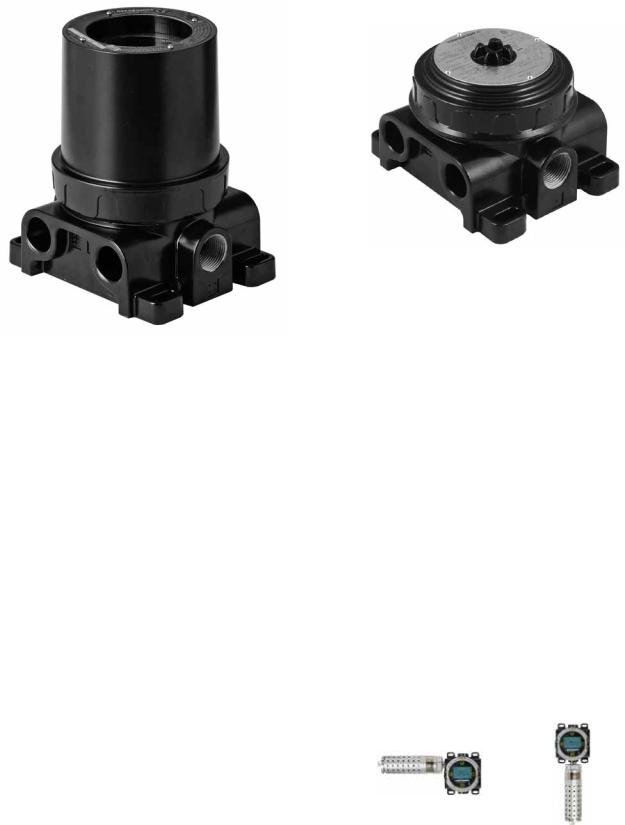
Figure 6—Tall PIRTB with Window
INSTALLATION
IMPORTANT
Use only low vapor pressure silicone grease when lubricating threads on the PointWatch Detector and associated termination box. Do not get this grease on the optics of the detector. A suitable grease is listed in the “Spare Parts” section at the end of this manual. Do not use Hydrocarbon-based grease. Doing so will emit hydrocarbon vapors that will be measured by the detector, resulting in inaccurate gas level readings.
Detector Location
It is essential that the device be properly located to enable it to provide maximum protection. The most effective number and placement of sensors varies depending on the conditions at the job site. The individual designing the installation must rely on experience and common sense to determine the type and quantity of sensors and the best sensor locations to adequately protect the area. The following factors should be considered for every installation:
Figure 7—Short PIRTB
1.What kind of gas is to be detected? If it is lighter than air, place the sensor above the potential gas leak. Place the sensor close to the floor for gases that are heavier than air or for vapors resulting from flammable liquid spills. However, note that air currents can cause a gas that is heavier than air to rise. In addition, if the gas is hotter than ambient air or mixed with gases that are lighter than air, it could also rise.
2.How rapidly will the gas diffuse into the air? Select a location for the sensor as close as practical to the anticipated source of a gas leak.
3.Ventilation characteristics of the immediate area must also be considered. Movement of air may cause gas to accumulate more heavily in one area than another. The detector should be placed in the areas where the most concentrated accumulation of gas is anticipated. Also take into consideration the fact that many ventilation systems do not operate continuously.
4.Proper orientation is horizontal.
CORRECT INCORRECT
Recommended Orientation of the PIR9400
9.3 |
6 |
95-8440 |

5.The sensor should be accessible for maintenance.
6.Excessive heat or vibration can result in premature failure of any electronic device and should be avoided if possible.
NOTE
For additional information on determining the quantity and placement of gas detectors in a specific application, refer to the article titled “The Use of Combustible Detectors in Protecting Facilities from Flammable Hazards” contained in the Instrument Society of America (ISA) Transaction,Volume 20, Number 2.
0 to 100% LFL Linearized Output Options
The PointWatch IR Detector is provided with five field selectable “standard gas” signal processing program settings. These settings create a linearized scale for methane and other gases like ethane, propane, butane, ethylene, or propylene, and are defined as linearized PointWatch gas measurement outputs. This means that the detector is capable of providing an analog signal output that is directly proportional to the % LFL concentration for these gases, provided the proper gas setting has been selected, and the it has been calibrated with the proper calibration gas type.
The PointWatch Detector is factory configured for 0 to 100% LFL methane. To re-configure the detector for one of the other gases, remove the electronic module from the housing and select the desired gas by changing the setting on the rotary gas selection switch. (Refer to “Changing Linearized Output Gas Selection.”) The detector must then be calibrated using a 50% LFL mixture of the selected gas.
NOTE
Failure to calibrate the device with a 50% LFL mixture of the selected gas will result in a sensor fault and improper operation of the detector.
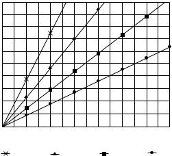
Response of Methane-Calibrated PointWatch Detector (Factory Setting) to Other Gases
Figure 8 shows the signal output of a PIR9400 that has been properly calibrated for methane in response to other gases. This data should be used as a reference only. It is recommended to always calibrate the detector with the type of gas to be detected.
RESPONSE OF METHANE CALIBRATED POINTWATCH TO OTHER GASES
|
110 |
|
|
|
|
|
|
|
|
|
|
|
|
100 |
|
|
|
|
|
|
|
|
|
|
|
|
90 |
|
|
|
|
|
|
|
|
|
|
|
(% LFL) |
80 |
|
|
|
|
|
|
|
|
|
|
|
70 |
|
|
|
|
|
|
|
|
|
|
|
|
OUTPUT |
|
|
|
|
|
|
|
|
|
|
|
|
60 |
|
|
|
|
|
|
|
|
|
|
|
|
|
|
|
|
|
|
|
|
|
|
|
|
|
POINTWATCH |
50 |
|
|
|
|
|
|
|
|
|
|
|
40 |
|
|
|
|
|
|
|
|
ETHANE |
|
||
|
|
|
|
|
|
|
|
|
|
|||
30 |
|
|
|
|
|
|
|
|
PROPANE |
|
||
|
|
|
|
|
|
|
|
|
|
|
|
|
|
20 |
|
|
|
|
|
|
|
|
ETHYLENE |
|
|
|
|
|
|
|
|
|
|
|
|
|
|
|
|
10 |
|
|
|
|
|
|
|
|
PROPYLENE |
|
|
|
|
|
|
|
|
|
|
|
|
|
|
|
C2019 |
0 |
|
|
|
|
|
|
|
|
|
|
|
|
0 |
10 |
20 |
30 |
40 |
50 |
60 |
70 |
80 |
90 |
100 |
110 |
|
|
|
|
|
|
%LFL GAS |
|
|
|
|
|
|
Figure 8—Response of Methane-Calibrated
PIR9400 (Factory Setting) to Other Gases, at
Tamb = 25°C
PointWatch Model PIR9400 Transfer Curves
The gas detector, when set for methane, provides detection of other hydrocarbon vapors at higher LFL readings (see Figure 8). In addition to the standard gases previously mentioned, the PointWatch Detector is capable of detecting and measuring many other hydrocarbon gases and vapors. Although linear detector outputs are not offered for most of these gases, an accurate gas concentration measurement can be made by using a cross-reference data sheet known as a “transfer curve.” (Available upon request.) The transfer curve data sheet is always based upon the following:
1.The data applies to one specific gas/vapor type only.
2.The data is collected at a specific test temperature. (Significant differences in ambient hazard area temperature as compared to test temperature may impact transfer curve accuracy.)
3.The data compares actual hazardous gas concentration in %LFL to the detector signal output level, using all five standard gas settings.
The transfer curve data is then used:
1.To select the optimum detector standard gas setting.
2.To select the appropriate setpoint levels for proper alarm relay actuation. This will ensure that external alarm response action occurs as required.
9.3 |
7 |
95-8440 |
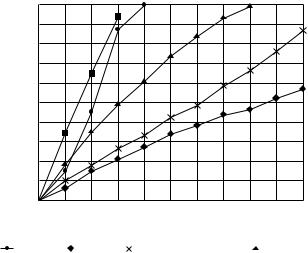
POINTWATCH GAS RESPONSE CURVES
|
100 |
|
|
|
|
|
|
|
|
|
|
|
90 |
|
|
|
|
|
|
|
|
|
|
(% LFL) |
80 |
|
|
|
|
|
|
|
|
|
|
70 |
|
|
|
|
|
|
|
|
|
|
|
OUTPUT |
|
|
|
|
|
|
|
|
|
|
|
60 |
|
|
|
|
|
|
|
|
|
|
|
|
|
|
|
|
|
|
|
|
|
|
|
POINTWATCH |
50 |
|
|
|
|
|
|
|
|
|
|
40 |
|
|
|
|
|
|
|
|
|
|
|
30 |
|
|
|
|
|
|
|
|
|
|
|
|
20 |
|
|
|
|
|
|
|
|
|
|
|
10 |
|
|
|
|
|
|
|
|
|
|
C2020 |
0 |
|
|
|
|
|
|
|
|
|
|
|
0 |
10 |
20 |
30 |
40 |
50 |
60 |
70 |
80 |
90 |
100 |
GASOLINE %LFL
METHANE |
|
ETHANE |
|
PROPANE |
|
|
|
ETHYLENE |
|
PROPYLENE |
Figure 9—Example of a PIR9400 Transfer Curve for Gasoline, at Tamb = 25°C
It is important to note that whenever using transfer curve data, the Model PIR9400 analog signal output and any real-time visual display of that output (such as a digital display or bar graph) will be offset by a value indicated by the transfer curve data, and therefore must be externally correlated by the viewer.
The transfer curve data sheet for the gas of interest includes five different curves — one for each standard linearized output setting. To select the appropriate setting for the detector, find the curve that:
1.Provides the closest signal correlation across the desired gas measurement range, and
2.Ensures that the offset in the PIR9400 signal output versus gas concentration is an over-reading, as opposed to an unsafe under-reading.
Ideally, at 50% of full scale PIR9400 output (12 ma signal level) the detected gas level will equal 50% LFL gas concentration, and this relationship will remain proportional throughout the gas measurement range. In reality, however, transfer curve data is non-linear, and will result in varying offset levels from proportional linearity throughout the gas measurement range. Refer to the example in Figure 9.
To use the transfer curve data, find the concentration (in % LFL) for the gas of interest on the horizontal axis of the graph. Follow the vertical line up from that point until it intersects with a gas response curve. From the point of intersection, follow the horizontal line directly to the left until it intersects with the vertical axis of the graph.
The point of intersection with the vertical axis represents PIR9400 output (0-100% LFL reading, or 4-20 mA proportionally) in response to the actual gas concentration at the installation using that particular linearized output setting.
In the example for gasoline vapor detection (Figure 9), the recommended PIR9400 standard gas setting and calibration gas to use is propylene. When using this setting and calibration gas type, at 50% LFL gasoline concentration, the PIR9400 signal output will be 73% (15 mA). The propane and ethane settings would not be recommended, since the signal output level is much less than the actual gas concentration in the field. The methane and ethylene settings are acceptable, but will result in much higher readings than the gas level that is actually present in the field.
Contact Detector Electronics Corporation (Det-Tronics®) for additional information regarding PIR9400 transfer curves.
IR Module Removal and Gas Selection
IMPORTANT
Remove power before disassembling the PointWatch Detector.
The electronics module of the PIR9400 gas detector is field-removable. There are four different revisions of the IR module as listed below:
1.Aluminum type supplied with 6-32 captive flatblade screws.
2.Stainless steel type supplied with 6-32 caphead (Allen) screws (use 7/64 inch hex driver).
3.Aluminum type supplied with M5 caphead (Allen) screws.
4.Stainless steel type supplied with M5 caphead (Allen) screws.
The M5 metric caphead screws were implemented as a standard design beginning in mid-2003 in order to comply with ATEX product approval requirements. In addition, the electronics mounting cover is factorytightened to a torque setting of 15 Newton-meters, and requires the use of the cover removal tool. Do not use an improper tool such as pliers or vise grip.
1.Completely loosen the captive screws on the flat end of the detector using the appropriate tool (flatblade screwdriver or Allen wrench) and slide off the weather baffle assembly. See Figures 10 and 11.
9.3 |
8 |
95-8440 |
CAPTIVE SCREWS (2) |
INNER FILTER ASSEMBLY |
|
OUTER FILTER ASSEMBLY |
A1738
Figure 10—Aluminum PIR9400 Disassembly
END CAP
BAFFLE
 STAINLESS STEEL COLLAR
CAPTIVE HEX SCREWS (2) |
|
A1739 |
|
|
|
|
|
Figure 11—Stainless Steel |
PIR9400 Disassembly |
||
CAPTIVE SCREWS (2) |
|
MIRROR ASSEMBLY |
|
|
|
||
|
|
REFLECTOR TUBES (INSIDE) |
|
|
|
|
HYDROPHOBIC FILTER |
|
|
|
|
|
|
ELECTRONICS MOUNTING COVER |
|
|
|
|
BASE ASSEMBLY |
C1741
Figure 12—IR Module and Base Assemblies
COVER REMOVAL TOOL
ELECTRONICS MOUNTING
COVER
B1742
IR MODULE |
BASE |
3/8” RATCHET |
|
Figure 13—IR Module Removal
ACCESS TO GAS SELECTION SWITCH
|
GAS SELECTION SWITCH |
|||||
|
|
|
|
|
|
|
|
|
1 |
2 |
3 |
|
|
|
|
|
|
|
||
|
|
0 |
|
|
4 |
|
|
|
7 |
|
|
5 |
|
|
|
6 |
|
|||
|
|
|
|
|
||
|
|
|
|
|
||
|
0 |
= METHANE (FACTORY SETTING) |
||||
|
1 |
= ETHANE |
||||
|
2 |
= PROPANE/BUTANE |
||||
|
3 |
= ETHYLENE |
||||
A1740 |
4 |
= PROPYLENE |
||||
Figure 14—Gas Selection Switch Location at the Bottom of the Electronics Assembly
NOTE
A 3/8” ratchet is needed to use the Cover RemovalTool.
2.Unscrew the factory-tightened electronics mounting cover (see Figure 12) by rotating it counter-clockwise with the Cover Removal Tool (P/N 009170-001). Only apply torque to the threaded cover. Do not use improper tools such as pliers or vise grips. Do not twist or apply any force to the mirror assembly.
3.Slide the electronics mounting cover away from the base and pull the IR module out of the base as shown in Figure 13.
4.Using a small screwdriver, rotate the gas selection switch from position 0 (methane) to the desired position. Refer to Figure 14. Ensure that the tip of the arrow on the switch lines up with the position selected.
Reassemble
1.The module is “keyed” using different sized pins on the bottom of the module. Slide the IR module into the base and rotate it until the keyed holes are aligned, then press securely into place.
NOTE
The assembly is designed to fit in a specific orientation. If the keyed holes are not aligned, rotate 180° and try again.
2.Screw the electronics mounting cover clockwise onto the base assembly as shown in Figure 12.
IMPORTANT
Use the Cover Removal tool to retighten the electronics mounting cover at a torque setting of 15 Newton-meters. Do not overtighten. Do not use improper tools such as pliers or vise grips. Do not apply any torque to the mirror assembly or reflector tubes.
3.For the aluminum model, slide the outer filter assembly over the mirror assembly. The outer filter should be oriented with the solid portion toward the base of the detector. If it is not oriented correctly, the filter assembly will not slide onto the unit. Slide the inner filter assembly into the outer filter assembly and rotate until it is seated securely, then fasten the two captive screws using the appropriate tool. See Figure 10. For the stainless steel model, slide the stainless steel collar onto the base assembly, then slide the baffle onto the unit. Place the end cap on the baffle and rotate it until it is seated securely, then fasten the two screws using the appropriate tool. See Figure 11.
9.3 |
9 |
95-8440 |
 Loading...