


Instructions 95-8661
FlexVu® Explosion-Proof
Universal Display Unit
Model UD10
|
|
|
|
|
|
|
|
|
|
|
|
|
|
|
|
|
|
|
|
|
|
|
|
|
|
|
|
|
|
|
|
|
|
|
|
|
|
|
|
|
|
|
|
|
|
|
|
|
|
|
|
|
|
|
|
|
|
|
|
|
|
|
|
|
|
|
|
|
|
|
|
|
|
|
|
|
|
|
|
|
|
|
|
|
|
|
|
|
|
|
|
|
|
|
|
|
|
|
|
|
|
|
|
|
|
|
|
|
|
|
|
|
|
|
|
|
|
|
|
|
|
|
|
|
|
|
|
|
|
|
|
|
|
|
|
|
|
|
|
|
|
|
|
|
|
|
|
|
|
|
|
|
|
|
|
|
|
|
|
|
|
|
|
|
|
|
|
|
|
|
|
|
|
|
|
|
|
|
|
|
|
|
|
|
|
|
|
|
|
|
|
|
|
|
|
|
|
|
|
|
|
|
|
|
|
|
|
|
|
|
|
|
|
|
|
|
|
|
|
|
|
|
|
|
|
|
|
|
|
|
|
|
|
|
|
|
|
|
|
|
|
|
|
|
|
|
|
|
|
|
|
|
|
|
|
|
|
|
|
|
|
|
|
|
|
|
|
|
|
|
|
|
|
|
|
|
|
|
|
|
|
|
|
|
|
|
|
|
|
|
|
|
|
|
|
|
|
|
|
|
|
|
|
|
|
|
|
|
|
|
|
|
|
|
|
|
|
|
|
|
|
|
|
|
|
|
|
|
|
|
|
|
|
|
|
|
|
|
|
|
|
|
|
|
|
|
|
|
|
|
|
|
|
|
|
|
|
|
|
|
|
|
|
|
|
|
|
|
|
|
|
|
|
|
|
|
|
|
|
|
|
|
|
|
|
|
|
|
|
|
|
|
|
|
|
|
|
|
|
|
|
|
|
|
|
|
|
|
|
|
|
|
|
|
|
|
|
|
|
|
|
|
|
|
|
|
|
|
|
|
|
|
|
4.2 |
|
|
|
|
|
|
|
Rev: 9/12 |
95-8661 |
|||||||||||||||
|
|
|
|
|
|
|
||||||||||||||||||||
Table of Contents
application . . . . . . . . . . . . . . . . . . . |
. . |
.1. . . |
.Appendix. . . . |
H — UD10 WITH pir9400 pointwatch |
. .H-1 |
|||
DESCRIPTION . . . . . . . . . . . . . . . . . . . . . . |
. . |
|
..1. . . |
. Wiring . |
. . . . . . . . . . . . . . . . . . . . . . . . . . . . . |
. . |
H-1 |
|
HART Communication |
|
|
3 |
|
Installation Notes . . . . . . . . . . . . . . . . . . . . . |
. . |
H-2 |
|
. . |
|
|
Orientation |
|
H-2 |
|||
Magnetic Switches . . . . . . . . . . . . . . . |
. |
|
|
|
. . |
|||
|
..3. . . . . . |
|
|
|
||||
Relays |
|
|
4 |
|
Changing Operating Modes . . . . . . . . . . . . . |
. . |
H-3 |
|
. . |
|
|
Calibration . . . . . . . . . . . . . . . . . . . . . |
. .H.-3. . . |
||||
4-20 mA Output Modes |
|
|
4 |
|
||||
. . |
|
|
Menu Structure |
|
H-4 |
|||
Modbus / Fieldbus Compatibility . . . . . . . . |
. |
|
..4. . . |
|
. . |
|||
|
|
|
|
|
|
|||
Device Enclosure . . . . . . . . . . . . . . . |
. . |
.4 . . . . . . |
|
|
I-1 |
|||
|
|
|
|
Appendix I — UD10 WITH model pirecl . . . . . . . |
. . |
|||
Device Display . . . . . . . . . . . . . . . . |
. . |
..4 . . . . . . . |
|
|
I-1 |
|||
Logging |
|
|
5 |
|
Wiring . |
. . . . . . . . . . . . . . . . . . . . . . . . . . . . . |
. . |
|
. . |
|
|
Orientation . . . . . . . . . . . . . . . . . . . . . . . . . . |
. . |
.I-2 |
|||
IMPORTant SAFETY NOTES |
|
|
5 |
|
Calibration . . . . . . . . . . . . . . . . . . . . . |
. |
. .I.-3. . . . |
|
. . |
|
|
Menu Structure . . . . . . . . . . . . . . . . . . . . . . . |
. . |
.I-4 |
|||
INSTallation . . . . . . . . . . . . . . . . . . . . . . . |
. . |
..6. . . |
Appendix J — UD10 WITH OPEN PATH MODEL OPECL . . . J-1 |
|||||
|
Wiring |
|
|
J-1 |
||||
Identification of Vapor(s) to be Detected |
|
|
6 |
|
. . . . . . . . . . . . . . . . . . . . . . . . . . . . . |
. . |
||
. . |
|
|
Orientation |
|
J-3 |
|||
Identification of Detector Mounting Locations |
|
|
6 |
|
. . |
|||
. . |
|
|
Calibration . . . . . . . . . . . . . . . . . . . . . |
. |
. J.-3. . . . |
|||
WIRING |
|
|
7 |
|
OPECL Transmitter Lamp Fault Condition . . |
. . |
J-4 |
|
. . |
|
|
Menu Structure . . . . . . . . . . . . . . . . . . . . . . . |
. . |
J-4 |
|||
Power Supply Requirements . . . . . . . . . . . . |
. . |
|
..7. |
Appendix K — UD10 WITH NTMOS H2S Sensor |
|
K-1 |
||
Wiring Cable Requirements |
|
|
7 |
. . |
||||
. . |
|
|
Wiring |
|
|
K-1 |
||
Shield Connections . . . . . . . . . . . . . . . |
. . |
.7. . . . |
. . . . . . . . . . . . . . . . . . . . . . . . . . . . . |
. . |
||||
Installation Notes |
|
K-1 |
||||||
Jumper Setting for 4-20 mA Loop . . . . . . |
. |
. .7. . . |
|
. |
||||
|
Orientation |
|
K-4 |
|||||
Foundation Fieldbus |
|
|
7 |
|
. . |
|||
. . |
|
|
Calibration . . . . . . . . . . . . . . . . . . . . . |
. |
.K.-4. . . . |
|||
Wiring Procedure |
|
|
8 |
|
||||
. . |
|
|
Menu Structure |
|
K-5 |
|||
|
|
|
|
|
. . |
|||
STaRTUP . . . . . . . . . . . . . . . . . . . . . . . . . |
. |
|
|
Appendix L — UD10 WITH C706X ToXIC GAS SENSOR |
. L-1 |
|||
..12. . . . . |
|
|
|
|
||||
Troubleshooting . . . . . . . . . . . . . . . . . . . . . |
. . |
|
16 |
|
Wiring . |
. . . . . . . . . . . . . . . . . . . . . . . . . . . . . |
. . |
L-1 |
SPECIFICATIONS |
|
|
19 |
|
Installation . . . . . . . . . . . . . . . . . . . . . . |
. |
. L.-3. . . |
|
. . |
|
|
Calibration . . . . . . . . . . . . . . . . . . . . . |
. |
. L.-4. . . . |
|||
Device Repair and Return |
|
|
22. |
|
||||
. . |
|
|
Menu Structure |
|
L-4 |
|||
Ordering Information . . . . . . . . . . . |
. .22. . . . . |
. . |
||||||
|
|
. . .M-1 |
||||||
|
|
|
|
Appendix M — UD10 with Model CGS Sensor |
||||
APPENDIX A — FM Approval description . . . . a-1 appendix b — csa certification description . b-1 appendix C — atex approval description . . . . . c-1 appendix d — iecEx approval description . . . . d-1 Appendix E — Additional Approvals . . . . . . . E.-.1.
Appendix F — UD10 WITH Handheld Hart
communicator . . . . . . . . . . . . . . . . . . . . . . . . . . . . . . . F-1
Wiring . . . . . . . . . . . . . . . . . . . . . . . . . . . . . . . . F-1
Menu Structure . . . . . . . . . . . . . . . . . . . . . . . . . F-1
Appendix G — UD10 WITH gt3000 toxic gas detector . . . . . . . . . . . . . . . . . . . . . . . . . . . . . . . . . . . .G-1
Wiring . . . . . . . . . . . . . . . . . . . . . . . . . . . . . . . . G-1 Orientation . . . . . . . . . . . . . . . . . . . . . . . . . . . . G-2 Live Maintenance . . . . . . . . . . . . . . . . . . . . . . . G-2 Calibration . . . . . . . . . . . . . . . . . . . . . . .G.-3. . .
Menu Structure . . . . . . . . . . . . . . . . . . . . . . . . . G-4
Wiring. . . . . . . . . . . . . . . . . . . . . . . . . . . . . . . . M-1 Important Notes . . . . . . . . . . . . . . . . . . . . . . . . M-1 Installation. . . . . . . . . . . . . . . . . . . . . . . . . . . . M-3 Calibration. . . . . . . . . . . . . . . . . . . . . . . . . . . . M-3 K-Factor.. .. .. .. .. .. .. .. .. .. .. .. .. .. .. .. .. .. .. .. .. .. .. .. .. .. .. .. .. .. M-4 Menu Structure. . . . . . . . . . . . . . . . . . . . . . . . . M-4
Appendix N — UD10 WITH Model 505/CGS . . . . . . . .N-1
Wiring . . . . . . . . |
. . . . . . . . . . . . . . . . . . . . . . |
. . N-1 |
Installation . . . |
. . . . . . . . . . . . . . . . . . . |
. ..N.-2. . |
Orientation . . . . |
. . . . . . . . . . . . . . . . . . . . . . . |
. N-2 |
Calibration . . . |
. . . . . . . . . . . . . . . . . . |
. .N.-3. . . |
Menu Structure . |
. . . . . . . . . . . . . . . . . . . . . . . |
. N-4 |
Appendix O — UD10 WITH Generic 4-20 ma sensor O-1
Operation . . . . . . . . . . . . . . . . . . . . . . . . . . . . . O-1 Menu Structure . . . . . . . . . . . . . . . . . . . . . . . . . O-1

INSTRUCTIONS
FlexVu® Explosion-Proof
Universal Display Unit
Model UD10
Important
Be sure to read and understand the entire instruction manual before installing or operating the gas detection system. This product can be used with a variety of Det-Tronics gas detectors to provide early warning of the presence of a toxic or explosive gas mixture. Proper device installation, operation, and maintenance is required to ensure safe and effective operation. If this equipment is used in a manner not specified in this manual, safety protection may be impaired.
Application
The FlexVu® Model UD10 is recommended for applications that require a gas detector with digital readout of detected gas levels as well as analog 4-20 mA output with HART, relay contacts, and Modbus RS485 (foundation™ Fieldbus option available). The UD10 Universal Display Unit is designed for use with Det Tronics gas detectors listed in Table 1.
The display unit is designed and approved as a ‘stand alone’ device and performs all the functions of a gas controller.
When furnished with the CGS interface board, the device can be used only with a CGS sensor for detection of combustible gas. The UD10/CGS combination is certified as a “Gas Detector”.
Gas concentration and unit of measurement are displayed on a digital display. The display unit provides a linear isolated/non-isolated 4-20 mA DC output signal (with HART) that corresponds to the detected gas concentration.
All electronics are enclosed in an explosion-proof aluminum or stainless steel housing. The display unit is used with a single detector that may be either coupled directly to the UD10, or remotely located using a sensor termination box.
The UD10 features non-intrusive calibration. A magnet is used to perform calibration as well as to navigate the UD10’s internal menu.
4.2©Detector Electronics Corporation 2012
Description
The UD10 Universal Display can be used with various 4-20 mA gas detection devices, with or without HART. The unit provides display, output and control capabilities for the gas detector.
The UD10 utilizes the following I/O:
Signal Inputs: |
4-20 mA loop from the sensing device |
|
User Inputs: |
Magnetic switches (4) on the display |
|
|
panel |
|
|
HART communication (handheld field |
|
|
communicator or AMS) |
|
|
foundation™ Fieldbus (if selected) |
|
Signal Outputs: |
4-20 mA output loop with HART |
|
|
Modbus RS485 or foundation™ Fieldbus |
|
|
Three alarm relays and one fault relay |
|
Visible Outputs: |
Backlit LCD display |
|
|
HART slave interface via HART |
|
|
Communicator |
|
|
Rev: 9/12 |
95-8661 |
Table 1—Range and Default Values for Alarms and Calibration Gas Concentration
|
|
UD10 Alarm DaTA |
|
|
Calibration |
|
|
|
|
|
|
|
|
Gas Detector |
|
High Alarm Value |
Low Alarm Value |
Aux alarm Value |
Cal Gas |
|
|
|
|
|
|
|
|
GT3000-- |
Range |
10-90% |
5-50% |
5-90% |
30-90% |
|
Hydrogen Sulfide |
Default |
40% |
10% |
40% |
50% |
|
|
|
|
|
|
|
|
GT3000-- |
Range |
10-90% |
5-50% |
5-90% |
30-90% |
|
Ammonia |
Default |
40% |
10% |
40% |
50% |
|
|
|
|
|
|
|
|
GT3000--Chlorine |
Range |
10-90% |
5-50% |
5-90% |
30-90% |
|
|
|
|
|
|
||
Default |
40% |
10% |
40% |
50% |
||
|
||||||
|
|
|
|
|
|
|
GT3000-- |
Range |
10-60% |
5-50% |
5-90% |
30-90% |
|
Hydrogen |
Default |
40% |
10% |
40% |
50% |
|
GT3000--Oxygen |
Range |
5-20.5% v/v |
5-20.5% v/v |
5-20.5% v/v |
20.9% v/v |
|
|
|
|
|
|
||
Default |
18% v/v |
18% v/v |
18% v/v |
20.9% v/v |
||
|
||||||
|
|
|
|
|
|
|
GT3000--Carbon |
Range |
10-90% |
5-50% |
5-90% |
30-90% |
|
Monoxide |
Default |
40% |
10% |
40% |
50% |
|
|
|
|
|
|
|
|
GT3000--Sulfur |
Range |
10-90% |
5-50% |
5-90% |
30-90% |
|
Dioxide |
Default |
40% |
10% |
40% |
50% |
|
|
|
|
|
|
|
|
PIR9400 |
Range |
10-60% |
5-50% |
5-90% |
50% |
|
|
|
|
|
|
||
Default |
40% |
10% |
40% |
50% |
||
|
||||||
|
|
|
|
|
|
|
PIRECL |
Range |
10-60% |
5-50% |
5-90% |
30-90% |
|
|
|
|
|
|
||
Default |
40% |
10% |
40% |
50% |
||
|
||||||
|
|
|
|
|
|
|
OPECL |
Range |
1-3 LFL-meters |
0.25-3 LFL-meters |
NA |
NA |
|
|
|
|
|
|
||
Default |
2 LFL-meters |
1 LFL-meter |
NA |
NA |
||
|
||||||
|
|
|
|
|
|
|
C706x* |
Range |
10-90% |
5-50% |
5-90% |
30-90% |
|
|
|
|
|
|
||
Default |
40% |
10% |
40% |
50% |
||
|
||||||
|
|
|
|
|
|
|
CGS |
Range |
10-60% |
5-50% |
5-90% |
50% |
|
Combustible |
Default |
40% |
10% |
40% |
50% |
|
|
|
|
|
|
|
|
Model 505/CGS |
Range |
10-60% |
5-50% |
5-90% |
N/A |
|
Combustible |
Default |
40% |
10% |
40% |
N/A |
|
|
|
|
|
|
|
|
NTMOS-- |
Range |
10-90% |
5-50% |
5-90% |
50% |
|
Hydrogen Sulfide |
Default |
40% |
10% |
40% |
50% |
|
|
|
|
|
|
|
|
Generic Detector |
Range |
10-90% |
5-50% |
5-90% |
N/A |
|
|
|
|
|
|
||
Default |
40% |
10% |
40% |
50% |
||
|
||||||
|
|
|
|
|
|
Notes: All values are a percentage of full scale with the exception of Oxygen, which is the actual percent of Oxygen, and OPECL, which is the value in LFL-meters.
low alarm must be less than or equal to the high alarm.
Changing the Measurement Range will reset all alarm and Cal Gas values to the default settings for the selected range.
Alarm relays are selectable for either normally energized or normally de-energized coils, with selectable latching or non-latching contacts. Fault relay is normally energized (with no faults).
*Does not support C7064C hydrogen sulfide or C7065E oxygen, but includes C7064E hydrogen sulfide, C7067E chlorine, C7066E carbon monoxide, and C7068E sulfur dioxide.
4.2 |
2 |
95-8661 |
HART communication
A HART interface provides device status information and field programming capability.
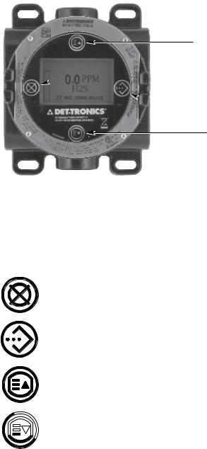
magnetic switches
Four internal magnetic switches provide a non intrusive user interface that allows navigation through the menu and adjustment of configuration parameters in the field without the use of a HART handheld device. See Figure 1 for switch locations.
PREVIOUS
 CANCEL / ESCAPE
 ENTER / SELECT
NEXT
B2426
Figure 1—Faceplate of UD10
These switches are used for device configuration, checking status and event logs, and performing calibration. The switches are labeled as follows:
CANCEL / ESCAPE
ENTER / SELECT / MeNU ACCESS
PrEVIOUS or if on Main Screen:
Fault Shortcut
 Next
Next
To actuate a magnetic switch, lightly touch the magnet to the viewing window of the UD10 directly over the switch icon on the faceplate.
Caution
Handle magnets with care! Personnel wearing pacemakers/defibrillators should not handle magnets. Modern magnet materials are extremely strong magnetically and somewhat weak mechanically. Injury is possible to personnel, and magnets themselves can easily get damaged if allowed to snap towards each other, or if nearby metal objects are allowed to be attracted to the magnets.
note
Det-Tronics offers two magnet options for activating internal magnetic switches. While the two magnets can usually be used interchangeably, the best results will be achieved if they are used as follows: The Magnetic Tool (p/n 009700-001) is the stronger magnet and is recommended for activating the switches on the UD10 viewing window. The Calibration Magnet (p/n 102740 002) is recommended for applications that involve initiating calibration or resetting the detector by touching the side of a metal junction box or detector housing (PIRECL, OPECL, etc). Throughout this manual, the term “magnet” can refer to either device.
Access To Menus
To access the menus, use the magnet to activate the Enter/SeLECT button. This will display the Main Menu.
The actual menu structure varies depending upon the device that is connected to the UD10. Menus for the various devices can be found in the corresponding Appendix in this manual.
Some areas of the menu contain additional information, which is indicated by the presence of an arrow on that particular line. By placing the magnet to the glass over the Enter/SeLECT button, the next screen with the additional information will be shown.
The UD10 automatically returns to the main screen after 10 minutes if no activity occurs.
Quick Access/Shortcut: Fault Menu
To access the fault menu quickly, when a fault is present, touch the magnet to the glass by the PrEVIOUS button.
4.2 |
3 |
95-8661 |

Relays
The display unit has 4 output relays — high alarm, low alarm, auxiliary alarm, and fault. The relays have form C (SPDT) contacts. Low, auxiliary and high alarm relay contacts are selectable for latching or non latching operation, as well as normally energized or normally de energized (default) coils. During normal operation, the fault relay is energized.
IMportant
Direct connection of 120/240 VAC to the relay terminals inside the UD10 enclosure is not allowed, since switching relay contacts can induce electrical noise into the electronic circuitry, possibly resulting in a false alarm or other system malfunction. If the application requires that AC powered equipment be controlled by the transmitter, the use of externally located relays is recommended.
External relays, solenoids, motors, or other devices that can cause inductive transients should be transient suppressed. Place a diode across the coil for DC devices. See Figure 2.
+ |
|
POSITIVE |
|
|||
|
|
|
1N4004 |
DCV LOADS |
||
|
|
|
|
|||
|
|
|
|
|||
|
|
|
|
|||
|
|
|
TYPICAL |
|
||
|
|
|
NEGATIVE |
|
||
|
|
|
|
|
|
|
|
|
|
|
|
|
|
|
|
|
– |
B0179 |
||
|
|
|
|
|||
|
|
|
|
|
|
|
Figure 2—Transient Suppression for Inductive Loads
4-20 mA OuTpuT Modes
The UD10 offers two operating modes for its 4-20 mA output circuit.
Note
A minimum output of 1 mA is required for proper HART communication.
In the Standard (default) Mode, the linear 4-20 mA output corresponds to 0-100% full scale gas detected at the sensor, with 3.8 mA indicating calibrate mode, and 3.6 mA or lower indicating a fault condition. This mode ensures that the current level is always high enough to support HART communication and must be selected when using HART communication for fault diagnostics.
In Replicate Mode, the output of the UD10 matches the output of the connected detector (except for loop test/trim, response test, calibration, or if the UD10 has an internal fault). This mode can be used with
detectors such as PIR9400 or PIRECL where multiple current levels below 4 mA are used for fault diagnostic purposes.
UD10 with Model PIRECL
PIRECL supports two fault modes: PIR9400 and Eclipse mode. PIR9400 fault mode uses fault codes below 1 mA, while Eclipse mode uses no levels below 1 mA. In the Standard (default) mode, the UD10 programs the PIRECL for Eclipse fault mode to ensure proper HART communication in the event of a fault. In the Replicate mode, the UD10 programs the PIRECL for PIR9400 fault mode.
MODBUS / fieldbus COMpATIBILITY
The UD10 supports RS485 Modbus RTU communication. See Addendum number 95-8639 for details. A model with Modbus RS485 or foundation™ Fieldbus communication (field selectable via jumpers) is also available.
DeviCE ENCLOSURE
The UD10 housing is a 5 port aluminum or stainless steel explosion proof junction box with a clear viewing window.
Device DISPLAY
The UD10 is provided with a 160 x 100 dot matrix backlit LCD display. See Figure 1.
During normal operation, the LCD continuously displays the detected gas level, gas type, and units of measurement. The real time clock can also be displayed if desired.
The display shows the following alarm information:
•High gas alarm
•Low gas alarm
•Aux alarm
The display indicates the following fault information:
•Device fault
•Display fault
The UD10 has smart capabilities to allow easy access to the following information:
•Detector information
•Measurement range
•Alarm setpoints
•Alarm and event logs
For detailed HART menu structure, refer to the appropriate Appendix.
4.2 |
4 |
95-8661 |
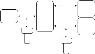
Logging
Events that can be logged in the UD10 include:
•Calibration (Date, time and success Y/N are logged for detectors that do not provide their own calibration logging capabilities.)
Faults that are logged in the UD10 include:
•Detector fault
•Low power
•General fault
Alarms that are logged in the UD10 for gas detector inputs include:
•High gas alarm
•Low gas alarm
•Aux alarm.
The UD10 has its own battery backed real time clock (RTC) and its own event logs. The RTC in the UD10 can be set from the UD10 display, Modbus or HART interfaces. The RTC in the gas detector (any HART detector having an RTC) can be set independently using the UD10 menu, or by using the synchronize command, which will set the detector RTC to the same time as the UD10 RTC. See Figure 3.
The UD10 can display the detector event and calibration logs (if available). The UD10 has its own 1,000 entry event log available under the Display Status >History >Event Log menu.
UD10 event logs can be read from the HART interface or the Modbus interface.
Detector calibration and event logs can also be read from the detector HART interface (where available).
|
|
MODBUS |
CONTROL |
|
|
or |
SYSTEM |
|
|
FOUNDATION FIELDBUS |
PLC/DCS |
|
|
|
|
GAS |
HART |
UD10 |
|
DETECTOR |
|
||
|
|
|
|
|
|
|
CONTROL |
|
|
HART |
SYSTEM |
|
|
PLC/DCS |
|
|
HART |
|
|
|
|
AMS |
|
|
Handheld |
|
|
|
|
|
|
|
|
HART |
|
|
|
Handheld |
|
important safety notes
CAUTIOn
The wiring procedures in this manual are intended to ensure proper functioning of the device under normal conditions. However, because of the many variations in wiring codes and regulations, total compliance to these ordinances cannot be guaranteed. Be certain that all wiring complies with the NEC as well as all local codes. If in doubt, consult the authority having jurisdiction before wiring the system. Installation must be done by a properly trained person.
CAUTIOn
This product has been tested and approved for use in hazardous areas. However, it must be properly installed and used only under the conditions specified within this manual and the specific approval certificates. Any device modification, improper installation, or use in a faulty or incomplete configuration will render warranty and product certifications invalid.
CAUTIOn
The device contains no user serviceable components. Service or repair should never be attempted by the user. Device repair should be performed only by the manufacturer.
LiabiLIties
The manufacturer’s warranty for this product is void, and all liability for proper function of the detector is irrevocably transferred to the owner or operator in the event that the device is serviced or repaired by personnel not employed or authorized by Detector Electronics Corporation, or if the device is used in a manner not conforming to its intended use.
Caution
Observe precautions for handling electrostatic sensitive devices.
caution
Unused conduit entries must be closed with suitably certified blanking elements upon installation.
Figure 3—UD10 Logging
4.2 |
5 |
95-8661 |
Installation
note
The gas detector housing must be electrically connected to earth ground. A dedicated earth ground terminal is provided on the UD10.
Note
Refer to the Model UD10 Safety Manual (number 95-8668) for specific requirements and recommendations applicable to the proper installation, operation, and maintenance of SILCertified Model UD10 displays.
The detector must always be installed per local installation codes.
Before installing the gas detector, define the following application details:
IdENTIFICATION of vapoR(s) to be detected
It is necessary to identify the vapor(s) of interest at the job site. The fire hazard properties of the vapor, such as vapor density, flashpoint, and vapor pressure should be identified and used to assist in selecting the optimum detector mounting location within the area.
For cross sensitivity information, refer to each gas detector’s corresponding instruction manual. Refer to Table 5 in the Specifications section for a list of gas detectors and their corresponding instruction manuals.
IdENTIFICATION of detector moUNTINg loCATIONS
Identification of the most likely leak sources and leak accumulation areas is typically the first step in identifying the best detector mounting locations. In addition, identification of air current/wind patterns within the protected area is useful in predicting gas leak dispersion behavior. This information should be used to identify optimum detector installation points.
If the vapor of interest is lighter than air, place the detector above the potential gas leak. Place the detector close to the floor for gases that are heavier than air. Note that air currents may cause a gas that is slightly heavier than air to rise under some conditions. Heated gases may also exhibit the same phenomenon.
The most effective number and placement of detectors varies depending on the conditions on site. The individual designing the installation must often rely on experience and common sense to determine the detector quantity and best locations to adequately protect the area. Note that it is typically advantageous to locate detectors where they are accessible for maintenance. Locations near excessive heat or vibration sources should be avoided.
Final suitability of possible gas detector locations should be verified by a job site survey.
The gas detector must be mounted with the sensor in the correct orientation as shown in Table 2.
If the UD10 faceplate is not correctly oriented, it can be rotated at 90 degree increments by pulling the electronic module from the four mounting posts that secure it to the junction box and repositioning it as desired. Note that the module is held in place by a compression fitting – no screws are involved.
|
Table 2—Device Orientation |
|
|
|
|
Device |
|
Orientation |
|
|
|
GT3000 |
|
Vertical with Sensor Pointing Down |
|
|
|
PIR9400 |
|
Horizontal |
|
|
|
PIRECL |
|
Horizontal |
|
|
|
OPECL |
|
Horizontal (Fixed to a vertical post) |
|
|
|
CGS |
|
Vertical with Sensor Pointing Down |
|
|
|
505/CGS |
|
Vertical with Sensor Pointing Down |
|
|
|
C706X |
|
Vertical with Sensor Pointing Down |
|
|
|
NTMOS |
|
Vertical with Sensor Pointing Down |
|
|
|
4.2 |
6 |
95-8661 |
WIRING
power SUPply requiremeNTS
Calculate the total gas detection system power consumption rate in watts from cold start-up. Select a power supply with adequate capability for the calculated load. Ensure that the selected power supply provides regulated and filtered 24 Vdc output power for the entire system. If a back-up power system is required, a float type battery charging system is recommended. If an existing source of 24 Vdc power is being utilized, verify that system requirements are met. The acceptable voltage range is 18-30 Vdc measured at the input to the UD10.
note
The power supply must meet the noise requirements for HART systems. If noise or ripple on the main power source could interfere with the HART function, an isolated power source (Figure 11) is recommended. (For detailed information regarding power supply specifications, refer to the HART Communication Foundation’s document “FSK Physical Layer Specification” HCF_SPEC-54.)
Wiring cable requiremeNTS
Always use proper cabling type and diameter for input power as well as output signal wiring. 14 to 18 AWG shielded stranded copper wire is recommended. Correct wire size depends on the device and wire length. Refer to the appropriate Appendix for additional information. The maximum cable length from power source to UD10 is 2000 feet. Maximum cable length from UD10 to sensor is 2000 feet.
note
The use of shielded cable in conduit or shielded armored cable is highly recommended. In applications where the wiring is installed in conduit, dedicated conduit is recommended. Avoid low frequency, high voltage, and non signaling conductors to prevent nuisance EMI problems.
caution
The use of proper conduit installation techniques, breathers, glands, and seals is required to prevent water ingress and/or maintain the explosion-proof rating.
ShIEld CoNNECTIONS
The UD10 provides terminals for proper grounding of wiring cable shields (located on the sensor, 4-20 mA, and operating power terminal blocks). These shield terminals are not connected internally, but are connected to ground through capacitors. The capacitors ensure an RF ground, while preventing 50/60 Hz ground loops.
Ground all shields as shown in the wiring examples throughout this manual.
important
For proper grounding, all junction boxes / metal enclosures must be connected to earth ground.
The following are required for installations requiring CE Mark compliance:
•For shielded cable installed in conduit, attach the wire shields to the “shield” connections on the terminal blocks, or to earth ground on the case.
•For installations without conduit, use double shielded cable. Terminate the outer shield to earth ground on the case. Terminate the inner shield to the “shield” connection on the terminal blocks.
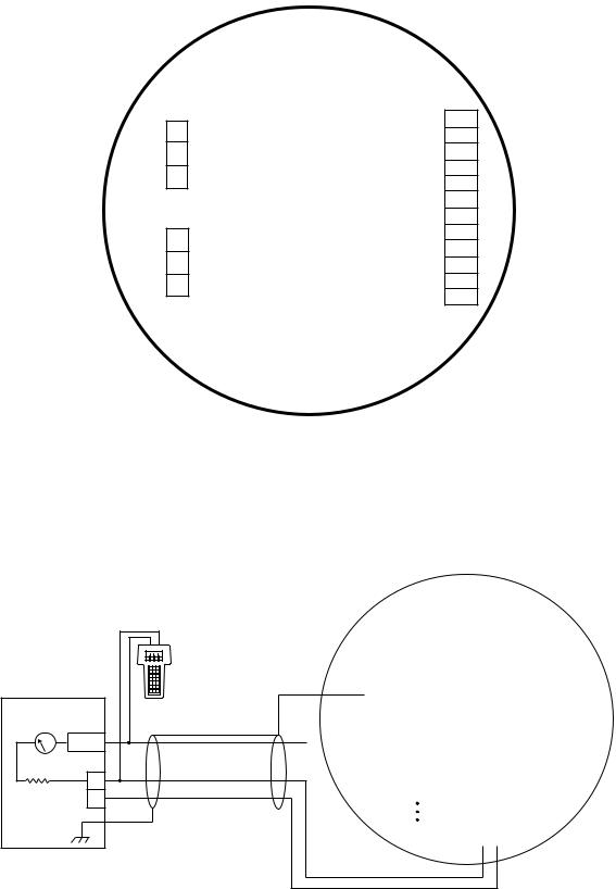
JumpeR SeTTINg for 4-20 mA Loop
In order for the 4-20 mA current loop to operate properly, +24 Vdc must be applied to terminal P1-3. This can be accomplished in one of two ways:
•For a non-isolated 4-20 mA loop, set jumper plug as shown in Figure 4. This applies +24 Vdc to P1-3 via an internal connection to terminals P2-2 and P2-5.
•If the 4-20 mA loop will receive power from a source other than the UD10’s main power source (isolated), set the jumper plug as shown in Figure 5 to remove the internal connection.
FoUNDATION FiEldbus (Optional)
Some UD10 models allow the use of either RS485/ MODBUS or Foundation Fieldbus communication via connection to J2 on the terminal board. Four jumpers are provided to select between the two protocols. If the device is equipped for Foundation Fieldbus, it will be shipped from the factory with the jumpers preset for that mode. If the user wants to switch to RS485/MODBUS (for example, to retrieve logs), the four jumpers can easily be moved. Figures 6 and 7 show the jumper settings for each mode of communication.
Note that the pin identification for the J2 connector is different for each communication protocol. For Foundation Fieldbus it is “– +”. For RS485/MODBUS it is “B A com”.
4.2 |
7 |
95-8661 |

Wiring Procedure
NOTE
The following section shows the output of the UD10 wired to a generic 4-20 mA signal receiver in various configurations. Since the UD10 can be used with a variety of different detection devices, information that is specific to each detector model (wiring, calibration, HART menus, etc.) is covered in an Appendix that is dedicated to that device. Refer to the appropriate Appendix at the back of this manual for specific information when wiring the detection system. For information on devices not covered in an Appendix, refer to the manual provided by the device’s manufacturer.
Figure 4 shows jumper plug P12 positioned to power the 4-20 mA loop from the main power source (non isolated output).
Figure 5 shows jumper plug P12 positioned for powering the 4-20 mA loop from an external wire/jumper of from a separate power source (isolated output).
Figure 6 shows the correct jumper positions and J2 terminal identification for using Foundation Fieldbus communication.
Figure 7 shows the correct jumper positions and J2 terminal identification for using MODBUS communication.
Refer to Figure 8 for an illustration of the UD10 wiring terminal board (see Figure 6 for Foundation Fieldbus connections).
Figure 9 shows a UD10 Wired to a PLC using 3-Wire Shielded Cable with a 4-20 mA Non-Isolated Sourcing Output.
Figure 10 shows a UD10 Wired to a PLC using 4-Wire Shielded Cable with a 4-20 mA Non-Isolated Sourcing Output.
Figure 11 shows a UD10 Wired to a PLC with a 4-20 mA Isolated Sourcing Output.
GREASE/LUBRICATION
To ease installation and future removal, ensure that all junction box covers and sensor threads are properly lubricated. If the need arises for additional lubrication, use either Lubriplate grease (see Ordering Information for part number) or Teflon tape. Avoid the use of silicone grease.
WHEN P12 IS
IN THIS POSITION, P1-3 IS INTERNALLY CONNECTED TO P2-2 AND P2-5
Sensor Connector
|
|
|
|
|
-1 |
-2 |
-3 |
-4 |
-5 |
|
J3 |
|
|
|||||||
|
|
|
|
|
J3 |
|
J3 |
J3 |
|
J3 |
|
J3 |
|
|
|
|||||
|
|
|
|
|
|
|
|
|
|
|
|
|||||||||
|
|
|
|
|
|
SHIELD |
|
CALIBRATE |
24 VDC – |
|
4-20 mA |
|
24 VDC + |
|
|
|
|
|||
|
|
4-20 mA + |
|
|
HIGH ALARM COM |
J4-1 |
||||||||||||||
|
P1-3 |
|
|
|
|
|
|
|
|
|
|
|
|
|
HIGH ALARM NC |
J4-2 |
||||
Output |
P1-2 |
4-20 mA – |
|
|
|
|
|
|
|
|
|
|
|
|
|
HIGH ALARM NO |
J4-3 |
|||
Loop |
|
|
|
|
|
|
|
P3 |
|
|
|
|
|
|
|
|
|
AUX ALARM COM |
J4-4 |
|
Connector |
P1-1 |
SHIELD |
|
|
|
|
|
|
|
|
|
|
|
|
|
AUX ALARM NC |
J4-5 |
|||
|
|
|
|
|
|
|
|
|
|
|
|
|
|
|
|
|
|
|||
|
P1 |
|
|
|
|
|
|
|
|
|
|
|
|
|
|
|
|
AUX ALARM NO |
J4-6 |
|
|
J2 |
|
|
|
|
|
|
|
|
|
|
|
|
|
|
|
|
LOW ALARM COM |
J4-7 |
|
Fieldbus |
J2-3 |
|
|
|
|
|
|
|
|
|
|
|
|
|
|
|
|
LOW ALARM NC |
J4-8 |
|
Connector |
|
+ |
|
|
|
|
|
|
|
|
|
|
|
|
|
|
|
LOW ALARM NO |
J4-9 |
|
J2-2 |
|
|
|
|
|
|
|
|
|
|
|
|
|
|
||||||
|
|
|
|
|
|
|
|
|
|
|
|
|
|
|
|
|
FAULT COM |
J4-10 |
||
|
|
|
|
|
|
|
|
|
|
|
|
|
|
|
|
|
|
|
||
|
J2-1 |
– |
|
|
|
|
|
|
|
|
|
|
|
|
|
|
FAULT NC |
J4-11 |
||
P5 |
|
|
|
|
|
|
|
|
|
|
|
|
|
|
|
|
|
|
FAULT NO |
J4-12 |
P9 |
|
|
|
|
|
–VDC24 |
|
+VDC24 |
|
|
SHIELD |
|
|
VDC24– |
|
+VDC24 |
|
SHIELD |
|
J4 |
|
|
|
|
P7 |
|
|
|
|
|
|
|
|
|
|
|
|
|
|
||
|
|
|
|
|
|
|
|
|
|
|
|
|
|
|
|
|
|
|
|
|
|
|
|
|
|
|
|
|
|
|
|
|
|
|
|
|
|
|
|
|
|
|
|
|
|
|
|
|
|
|
|
|
|
|
|
|
|
|
|
|
|
|
|
|
|
|
|
|
-6 |
|
-5 |
-4 |
|
-3 |
|
-2 |
|
-1 |
P2 |
|
|||
|
|
|
|
P12 |
|
P2 |
|
P2 |
|
P2 |
|
|
P2 |
|
P2 |
|
P2 |
|
|
|
Power Supply Connector
Relay Connector
B2525
WHEN P12 IS IN
THIS POSITION, A SEPARATE POWER SOURCE IS REQUIRED TO POWER THE
4-20 MA LOOP
Sensor Connector
|
|
|
|
|
|
|
|
|
|
-1 |
-2 |
-3 |
-4 |
-5 |
|
J3 |
|
||||
|
|
|
|
|
|
|
|
|
|
J3 |
|
J3 |
J3 |
|
J3 |
J3 |
|
|
|||
|
|
|
|
|
|
|
|
|
|
|
|
|
|
|
|||||||
|
|
|
|
|
|
|
|
|
|
|
SHIELD |
|
CALIBRATE |
24 VDC – |
|
4-20 mA |
24 VDC + |
|
HIGH ALARM COM |
||
|
P1-3 |
4-20 mA + |
|
|
|
|
|
|
|
|
|
|
|
HIGH ALARM NC |
|||||||
Output |
P1-2 |
4-20 mA – |
|
|
|
|
|
|
|
|
|
|
|
HIGH ALARM NO |
|||||||
|
|
|
|
|
|
|
|
|
|
|
|
|
|||||||||
Loop |
|
|
|
|
|
|
|
|
|
|
|
|
P3 |
|
|
|
|
|
|
AUX ALARM COM |
|
Connector |
P1-1 |
SHIELD |
|
|
|
|
|
|
|
|
|
|
|
AUX ALARM NC |
|||||||
|
|
|
|
|
|
|
|
|
|
|
|
|
|
|
|
|
|
|
|
||
|
|
P1 |
|
|
|
|
|
|
|
|
|
|
|
|
|
|
|
|
|
AUX ALARM NO |
|
|
|
J2 |
|
|
|
|
|
|
|
|
|
|
|
|
|
|
|
|
|
LOW ALARM COM |
|
Fieldbus |
|
J2-3 |
|
|
|
|
|
|
|
|
|
|
|
|
|
|
|
|
|
LOW ALARM NC |
|
Connector |
|
|
+ |
|
|
|
|
|
|
|
|
|
|
|
|
|
|
|
LOW ALARM NO |
||
|
J2-2 |
|
|
|
|
|
|
|
|
|
|
|
|
|
|
||||||
|
|
|
|
|
|
|
|
|
|
|
|
|
|
|
|
|
|
FAULT COM |
|||
|
|
|
|
|
|
|
|
|
|
|
|
|
|
|
|
|
|
|
|
|
|
|
|
J2-1 |
– |
|
|
|
|
|
|
|
|
|
|
|
|
FAULT NC |
|||||
P5 |
|
|
|
|
|
|
|
|
|
|
|
|
|
|
|
– |
|
|
|
|
FAULT NO |
|
|
|
|
|
|
|
|
|
|
|
|
|
|
|
|
|
|
|
|||
P9 |
|
|
|
|
|
|
|
|
P7 |
|
|
SHIELD |
|
|
|
|
|
|
|||
|
|
|
|
|
|
|
|
|
|
|
24VDC– |
|
24VDC+ |
|
24VDC |
|
24VDC+ |
|
SHIELD |
|
|
|
|
|
|
|
|
|
|
|
|
|
|
|
|
|
|
||||||
|
|
|
|
|
|
|
|
|
|
|
-6 |
|
-5 |
-4 |
|
-3 |
-2 |
|
-1 |
P2 |
|
|
|
|
|
|
|
|
|
P12 |
|
|
P2 |
|
P2 |
P2 |
|
P2 |
|
P2 |
|
P2 |
|
Power Supply Connector
J4-1 |
|
J4-2 |
|
J4-3 |
|
J4-4 |
Connector |
J4-5 |
|
J4-6 |
|
J4-7 |
Relay |
J4-8 |
|
J4-9 |
|
J4-10 |
|
J4-11 |
|
J4-12 |
|
J4 |
|
B2526
Figure 4—Position of Jumper P12 for Non-Isolated 4-20 mA Loop Output
Figure 5—Position of Jumper P12 for Isolated 4-20 mA Loop Output
4.2 |
8 |
95-8661 |
Sensor Connector
|
|
|
J3-1 |
J3-2 |
|
J3-3 |
J3-4 |
J3-5 |
||
|
|
|
|
|
|
|
|
|
|
|
|
|
|
SHIELD |
CALIBRATE |
|
24 VDC – |
4-20 mA |
24 VDC + |
||
|
P1-3 |
4-20 mA + |
|
|
|
|
|
|
|
|
Output |
|
4-20 mA – |
|
|
|
|
|
|
|
|
P1-2 |
|
|
|
|
|
|
|
|||
Loop |
|
|
|
|
|
|
|
|
|
|
|
|
|
|
P3 |
|
|
|
|
||
|
|
|
|
|
|
|
||||
Connector |
P1-1 |
SHIELD |
|
|
|
|
|
|
|
|
|
|
|
|
|
|
|
||||
|
|
|
|
|
|
|
|
|
|
|
|
P1 |
|
|
|
|
|
|
|
|
|
|
J2 |
|
|
|
|
|
|
|
|
|
Fieldbus |
|
|
|
|
|
|
|
|
|
|
J2-3 |
|
|
|
|
|
|
|
|
|
|
Connector |
|
|
|
|
|
|
|
|
|
|
J2-2 |
+ |
|
|
|
|
|
|
|
|
|
|
|
|
|
|
|
|
|
|
||
J2-1 |
– |
|
|
|
|
|
P5 |
|
|
|
|
|
|
P9 |
P7 |
– |
+ |
SHIELD |
– |
+ |
|
|
24 VDC |
24 VDC |
24 VDC |
24 VDC |
|
|
P12 |
P2-6 |
P2-5 |
P2-4 |
P2-3 |
P2-2 |
|
|
|
|
|
|
J3
HIGH ALARM COM |
J4-1 |
||
HIGH ALARM NC |
|
||
J4-2 |
|||
|
|
||
HIGH ALARM NO |
J4-3 |
||
|
|
||
AUX ALARM COM |
J4-4 |
||
|
|
||
AUX ALARM NC |
J4-5 |
||
|
|
||
AUX ALARM NO |
J4-6 |
||
|
|
||
LOW ALARM COM |
J4-7 |
||
|
|
||
LOW ALARM NC |
J4-8 |
||
|
|
||
LOW ALARM NO |
J4-9 |
||
|
|
|
|
|
|
FAULT COM |
J4-10 |
|
|
|
|
|
|
FAULT NC |
J4-11 |
|
|
FAULT NO |
|
|
|
J4-12 |
|
|
|
|
|
|
|
|
J4 |
SHIELD |
|
|
|
-1 |
|
P2 |
|
|
|
||
P2 |
|
|
|
|
|
|
|
|
|
|
|
Relay Connector
NOTE: FOUNDATION FIELDBUS IS AVAILABLE ON SELECT MODELS. REFER TO THE MODEL MATRIX IN THE ORDERING INFORMATION SECTION FOR DETAILS.
|
Power Supply Connector |
JUMPERS P3, P5, P7, AND P9 MUST BE POSITIONED AS SHOWN |
|
|
|
C2527 |
|
FOR FOUNDATION FIELDBUS COMMUNICATION |
Figure 6—Foundation Fieldbus Communication
Sensor Connector
|
|
|
J3-1 |
J3-2 |
|
J3-3 |
J3-4 |
J3-5 |
|
|
|
|
|
|
|
|
|
|
|
|
|
|
SHIELD |
CALIBRATE |
|
24 VDC – |
4-20 mA |
24 VDC + |
|
|
P1-3 |
4-20 mA + |
|
|
|
|
|
|
|
Output |
|
4-20 mA – |
|
|
|
|
|
|
|
P1-2 |
|
|
|
|
|
|
|||
Loop |
|
|
|
|
|
|
|
||
|
|
|
|
P3 |
|
|
|
||
|
|
|
|
|
|
||||
Connector |
P1-1 |
SHIELD |
|
|
|
|
|
|
|
|
|
|
|
|
|
||||
|
|
|
|
|
|
|
|
|
|
|
P1 |
|
|
|
|
|
|
|
|
|
J2 |
|
|
|
|
|
|
|
|
MODBUS |
J2-3 |
COM |
|
|
|
|
|
|
|
Connector |
|
RS485 A |
|
|
|
|
|
|
|
J2-2 |
|
|
|
|
|
|
|||
|
|
|
|
|
|
|
|||
|
|
RS485 B |
|
|
|
|
|
|
|
|
J2-1 |
|
|
|
|
|
|
||
|
|
|
|
|
|
|
|
|
|
P5 |
|
|
|
|
|
|
P9 |
P7 |
– |
+ |
SHIELD |
– |
+ |
|
|
24 VDC |
24 VDC |
24 VDC |
24 VDC |
|
|
P12 |
P2-6 |
P2-5 |
P2-4 |
P2-3 |
P2-2 |
|
|
|
|
|
|
J3
HIGH ALARM COM |
J4-1 |
||
HIGH ALARM NC |
|
||
J4-2 |
|||
|
|
||
HIGH ALARM NO |
J4-3 |
||
|
|
||
AUX ALARM COM |
J4-4 |
||
|
|
||
AUX ALARM NC |
J4-5 |
||
AUX ALARM NO |
J4-6 |
||
|
|
||
LOW ALARM COM |
J4-7 |
||
|
|
||
LOW ALARM NC |
J4-8 |
||
LOW ALARM NO |
J4-9 |
||
|
|
|
|
|
|
FAULT COM |
J4-10 |
|
|
|
|
|
|
FAULT NC |
J4-11 |
|
|
FAULT NO |
|
|
|
J4-12 |
|
|
|
|
J4 |
SHIELD |
|
|
|
-1 |
|
P2 |
|
|
|
||
P2 |
|
|
|
|
|
|
|
|
|
|
|
Relay Connector
|
Power Supply Connector |
JUMPERS P3, P5, P7, AND P9 MUST BE POSITIONED AS SHOWN |
|
|
|
B2528 |
|
FOR MODBUS/RS485 COMMUNICATION |
Figure 7—MODBUS Communication
4.2 |
9 |
95-8661 |
Output Loop
Connector
P1-3 4-20 mA +
P1-2 4-20 mA –
P1-1 SHIELD
P1
J2
J2-3 COM
J2-2 RS485 A
J2-1 RS485 B
MODBUS
Connector
Sensor Connector
-1 |
-2 |
-3 |
-4 |
-5 |
|
J3 |
|
|||||
J3 |
|
J3 |
|
J3 |
|
J3 |
|
J3 |
|
|
||
|
|
|
|
|
|
|
||||||
|
|
|
|
|
|
|
|
|
|
|
|
|
SHIELD |
CALIBRATE |
|
24 VDC – |
|
4-20 mA |
|
24 VDC + |
HIGH ALARM COM |
||||
|
|
|
|
|
|
|
|
|
|
|||
|
|
|
|
|
|
|
|
|
|
|
HIGH ALARM NC |
|
|
|
|
|
|
|
|
|
|
|
|
HIGH ALARM NO |
|
|
|
|
|
|
|
|
|
|
|
AUX ALARM COM |
||
|
|
|
|
|
|
|
|
|
|
|
AUX ALARM NC |
|
|
|
|
|
|
|
|
|
|
|
|
AUX ALARM NO |
|
|
|
|
|
|
|
|
|
|
|
LOW ALARM COM |
||
|
|
|
|
|
|
|
|
|
|
|
LOW ALARM NC |
|
|
|
|
|
|
|
|
|
|
|
|
LOW ALARM NO |
|
|
|
|
|
|
|
|
|
|
|
|
|
FAULT COM |
|
|
|
|
|
|
|
|
|
|
|
|
FAULT NC |
|
– |
+ |
|
SHIELD |
|
– |
+ |
|
SHIELD |
FAULT NO |
||
|
24 VDC |
|
24 VDC |
|
|
24 VDC |
|
24 VDC |
|
|
||
|
|
|
|
|
|
|
|
|
|
|
|
|
|
-6 |
|
-5 |
|
-4 |
|
-3 |
|
-2 |
|
-1 |
P2 |
|
P2 |
|
P2 |
|
P2 |
|
P2 |
|
P2 |
|
P2 |
|
|
|
|
|
|
|
|
||||||
Power Supply Connector
J4-1
J4-2
J4-3
J4-4
J4-5
J4-6
J4-7
J4-8
J4-9
J4-10
J4-11
J4-12
J4
Relay Connector
C2399
Figure 8—Wiring Terminals on UD10 Terminal Board
PLC 4-20 mA INPUT CARD
|
INPUT |
4-20 mA |
|
|
– |
250-600 |
24 VDC |
OHMS |
+ |
Notes: Resistor may be external if voltage input card is used. Sinking resistance at PLC must be 250-600 ohms
for HART communication.
UD10
DISPLAY UNIT
Sensor Connector
|
|
|
|
|
|
|
|
|
|
|
|
|
|
|
|
|
|
|
|
|
|
|
|
|
|
|
|
|
|
|
|
-1 |
-2 |
-3 |
-4 |
|
|
-5 |
|
|
|
J3 |
|
|
|
||||||||
|
|
|
|
|
J3 |
|
J3 |
|
J3 |
|
J3 |
|
J3 |
|
|
|
|
|||||||||
|
|
|
|
|
|
|
|
|
|
|
|
|
|
|||||||||||||
Output Loop |
SHIELD |
|
CALIBRATE |
|
VDC24 – |
|
20-4mA |
|
VDC24 + |
|
|
|
|
|
||||||||||||
Connector |
|
|
|
|
|
|
|
|
|
|
|
|
|
|
|
|
|
|
|
|
|
|
||||
|
|
4-20 mA + |
|
|
|
|
|
|
|
|
|
|
|
|
|
|
|
|
|
|
HIGH ALARM COM |
J4-1 |
|
|||
|
P1-3 |
|
|
|
|
|
|
|
|
|
|
|
|
|
|
|
|
|
|
HIGH ALARM NC |
J4-2 |
|
||||
|
|
|
|
|
|
|
|
|
|
|
|
|
|
|
|
|
|
|
|
|
|
|
|
|||
|
P1-2 |
4-20 mA – |
|
|
|
|
|
|
|
|
|
|
|
|
|
|
|
|
|
|
HIGH ALARM NO |
J4-3 |
|
|||
|
P1-1 |
SHIELD |
|
|
|
|
|
|
|
|
|
|
|
|
|
|
|
|
|
|
AUX ALARM COM |
J4-4 |
Connector |
|||
|
|
|
|
|
|
|
|
|
|
|
|
|
|
|
|
|
|
|
|
|
|
|||||
|
|
|
|
|
|
|
|
|
|
|
|
|
|
|
|
|
|
|
AUX ALARM NC |
J4-5 |
|
|||||
|
|
|
|
|
|
|
|
|
|
|
|
|
|
|
|
|
|
|
|
|
|
|
|
|||
|
P1 |
|
|
|
|
|
|
|
|
|
|
|
|
|
|
|
|
|
|
|
|
|
|
|
|
|
|
|
|
|
|
|
|
|
|
|
|
|
|
|
|
|
|
|
|
|
|
|
AUX ALARM NO |
J4-6 |
|
||
|
|
|
|
|
|
|
|
|
|
|
|
|
|
|
|
|
|
|
|
|
|
|
|
|||
|
|
|
|
|
|
|
|
|
|
|
|
|
|
|
|
|
|
|
|
|
|
|
|
|
|
|
|
J2 |
|
|
|
|
|
|
|
|
|
|
|
|
|
|
|
|
|
|
|
|
|
LOW ALARM COM |
J4-7 |
Relay |
|
|
|
|
|
|
|
|
|
|
|
|
|
|
|
|
|
|
|
|
|
|
|
|
|
|
||
|
|
COM |
|
|
|
|
|
|
|
|
|
|
|
|
|
|
|
|
|
|
LOW ALARM NC |
J4-8 |
||||
|
J2-3 |
|
|
|
|
|
|
|
|
|
|
|
|
|
|
|
|
|
|
|||||||
|
|
|
|
|
|
|
|
|
|
|
|
|
|
|
|
|
|
|
|
|
|
|
|
|||
|
|
RS485 A |
|
|
|
|
|
|
|
|
|
|
|
|
|
|
|
|
|
|
LOW ALARM NO |
J4-9 |
|
|||
|
J2-2 |
|
|
|
|
|
|
|
|
|
|
|
|
|
|
|
|
|
|
|||||||
|
|
|
|
|
|
|
|
|
|
|
|
|
|
|
|
|
|
|
|
FAULT COM |
J4-10 |
|
||||
|
|
|
|
|
|
|
|
|
|
|
|
|
|
|
|
|
|
|
|
|
|
|
|
|
|
|
|
J2-1 |
RS485 B |
|
|
|
|
|
|
|
|
|
|
|
|
|
|
|
|
|
|
|
FAULT NC |
J4-11 |
|
||
|
|
|
|
|
|
|
|
|
|
|
|
|
|
|
|
|
|
|
|
FAULT NO |
|
|
||||
|
|
|
|
|
|
|
– |
+ |
|
SHIELD |
|
|
– |
+ |
|
SHIELD |
J4-12 |
|
||||||||
|
MODBUS |
|
|
|
|
|
|
|
||||||||||||||||||
|
|
|
VDC24 |
|
VDC24 |
|
|
|
VDC24 |
|
|
VDC24 |
|
|
J4 |
|
||||||||||
|
Connector |
|
|
|
|
|
|
|
|
|
|
|
|
|
|
|
|
|
|
|
|
|
|
|
||
|
|
|
|
|
|
|
|
|
|
|
|
|
|
|
|
|
|
|
|
|
|
|
|
|
||
|
|
|
|
|
|
|
|
|
|
|
|
|
|
|
|
|
|
|
|
|
|
|
|
|
|
|
|
|
|
|
|
|
-6 |
|
-5 |
|
-4 |
|
-3 |
|
-2 |
|
-1 |
P2 |
|
|
|||||||
|
|
|
|
|
|
|
P2 |
|
P2 |
|
P2 |
|
|
P2 |
|
|
P2 |
|
P2 |
|
|
|||||
|
|
P12 |
|
|
|
|
|
|
|
|
|
|
|
|
|
|
|
|
|
|
|
|
|
|
||
Power Supply Connector
D2439
Figure 9—UD10 Wired to PLC using 3-Wire Shielded Cable with 4-20 mA Non-Isolated Sourcing Output
4.2 |
10 |
95-8661 |

UD10
DISPLAY UNIT
Sensor Connector
|
|
Output Loop |
|
|
|
Connector |
|
|
|
P1-3 |
4-20 mA + |
|
|
P1-2 |
4-20 mA – |
PLC 4-20 mA INPUT CARD |
P1-1 |
SHIELD |
|
|
|
||
|
|
P1 |
|
|
|
J2 |
|
|
INPUT |
J2-3 |
COM |
|
|
|
|
4-20 mA |
J2-2 |
RS485 A |
|
|
|
||
|
– |
J2-1 |
RS485 B |
|
|
|
|
250-600 |
24 VDC |
MODBUS |
|
OHMS |
+ |
Connector |
|
|
|
|
P12 |
Notes: Resistor may be external if voltage input card is used. Sinking resistance at PLC must be 250-600 ohms
for HART communication.
|
|
|
|
|
|
|
|
|
|
|
|
|
|
|
|
|
|
|
-1 |
-2 |
-3 |
-4 |
|
-5 |
|
|
J3 |
|
|
||||||||
J3 |
|
J3 |
|
J3 |
|
J3 |
|
J3 |
|
|
|
|||||||
|
|
|
|
|
|
|
|
|||||||||||
SHIELD |
|
CALIBRATE |
|
24 VDC – |
|
4-20 mA |
|
24 VDC + |
|
|
|
|
||||||
|
HIGH ALARM COM |
J4-1 |
||||||||||||||||
|
|
|
|
|
|
|
|
|
|
|
|
|
|
|
|
HIGH ALARM NC |
|
|
|
|
|
|
|
|
|
|
|
|
|
|
|
|
|
|
J4-2 |
||
|
|
|
|
|
|
|
|
|
|
|
|
|
|
|
|
HIGH ALARM NO |
J4-3 |
|
|
|
|
|
|
|
|
|
|
|
|
|
|
|
|
|
|
|
|
|
|
|
|
|
|
|
|
|
|
|
|
|
|
|
|
AUX ALARM COM |
J4-4 |
|
|
|
|
|
|
|
|
|
|
|
|
|
|
|
|
|
|
|
|
|
|
|
|
|
|
|
|
|
|
|
|
|
|
|
|
AUX ALARM NC |
J4-5 |
|
|
|
|
|
|
|
|
|
|
|
|
|
|
|
|
|
AUX ALARM NO |
J4-6 |
|
|
|
|
|
|
|
|
|
|
|
|
|
|
|
|
|
|
|
|
|
|
|
|
|
|
|
|
|
|
|
|
|
|
|
|
LOW ALARM COM |
J4-7 |
|
|
|
|
|
|
|
|
|
|
|
|
|
|
|
|
|
LOW ALARM NC |
J4-8 |
|
|
|
|
|
|
|
|
|
|
|
|
|
|
|
|
|
|
|
|
|
|
|
|
|
|
|
|
|
|
|
|
|
|
|
|
LOW ALARM NO |
J4-9 |
|
|
|
|
|
|
|
|
|
|
|
|
|
|
|
|
|
|
|
|
|
|
|
|
|
|
|
|
|
|
|
|
|
|
|
|
|
FAULT COM |
J4-10 |
|
|
|
|
|
|
|
|
|
|
|
|
|
|
|
|
|
|
|
|
|
|
|
|
|
|
|
|
|
|
|
|
|
|
|
|
FAULT NC |
J4-11 |
|
|
|
|
|
|
|
|
|
|
|
|
|
|
|
|
|
FAULT NO |
|
|
|
– |
+ |
|
|
|
|
– |
+ |
|
|
J4-12 |
||||||
|
|
|
SHIELD |
|
|
|
SHIELD |
|
|
|||||||||
|
|
VDC24 |
|
VDC24 |
|
|
|
VDC24 |
|
|
VDC24 |
|
|
J4 |
||||
|
|
|
|
|
|
|
|
|
|
|
|
|
|
|
|
|
|
|
|
-6 |
|
-5 |
|
-4 |
|
-3 |
|
-2 |
|
-1 |
P2 |
|
|||||
|
|
P2 |
|
P2 |
|
P2 |
|
|
P2 |
|
|
P2 |
|
P2 |
|
|||
|
|
|
|
|
|
|
|
|
|
|
||||||||
|
|
|
|
|
|
|
|
|
|
|
|
|
|
|
|
|
|
|
|
|
|
|
|
|
|
|
|
|
|
|
|
|
|
|
|
|
|
Power Supply Connector
Relay Connector
E2440
Figure 10—UD10 Wired to PLC using 4-Wire Shielded Cable with 4-20 mA Non-Isolated Sourcing Output
UD10
DISPLAY UNIT
Sensor Connector
|
|
Output Loop |
|
|
|
Connector |
|
|
|
P1-3 |
4-20 mA + |
|
|
P1-2 |
4-20 mA – |
PLC 4-20 mA INPUT CARD |
P1-1 |
SHIELD |
|
|
|
||
|
|
P1 |
|
|
|
J2 |
|
|
INPUT |
J2-3 |
COM |
|
|
|
|
4-20 mA |
J2-2 |
RS485 A |
|
|
|
||
|
– |
J2-1 |
RS485 B |
|
|
|
|
250-600 |
24 VDC |
MODBUS |
|
OHMS |
+ |
Connector |
|
|
|
|
P12 |
Notes: Resistor may be external if voltage input card is used. Sinking resistance at PLC must be 250-600 ohms
for HART communication.
|
|
|
|
|
|
|
|
|
|
|
|
|
|
|
|
|
|
|
|
-1 |
-2 |
-3 |
-4 |
|
-5 |
|
|
J3 |
|
|
|
||||||||
J3 |
|
J3 |
|
J3 |
|
J3 |
|
J3 |
|
|
|
|
|||||||
|
|
|
|
|
|
|
|
|
|||||||||||
SHIELD |
|
CALIBRATE |
|
24 VDC – |
|
4-20 mA |
|
24 VDC + |
|
|
|
|
|
||||||
|
HIGH ALARM COM |
J4-1 |
|
||||||||||||||||
|
|
|
|
|
|
|
|
|
|
|
|
|
|
|
|
HIGH ALARM NC |
|
|
|
|
|
|
|
|
|
|
|
|
|
|
|
|
|
|
|
J4-2 |
|
||
|
|
|
|
|
|
|
|
|
|
|
|
|
|
|
|
HIGH ALARM NO |
J4-3 |
|
|
|
|
|
|
|
|
|
|
|
|
|
|
|
|
|
|
|
|
|
|
|
|
|
|
|
|
|
|
|
|
|
|
|
|
|
|
AUX ALARM COM |
J4-4 |
Connector |
|
|
|
|
|
|
|
|
|
|
|
|
|
|
|
|
|
|
|
|
|
|
|
|
|
|
|
|
|
|
|
|
|
|
|
|
|
AUX ALARM NC |
J4-5 |
||
|
|
|
|
|
|
|
|
|
|
|
|
|
|
|
|
|
|||
|
|
|
|
|
|
|
|
|
|
|
|
|
|
|
|
AUX ALARM NO |
J4-6 |
|
|
|
|
|
|
|
|
|
|
|
|
|
|
|
|
|
|
|
|
|
|
|
|
|
|
|
|
|
|
|
|
|
|
|
|
|
|
LOW ALARM COM |
J4-7 |
Relay |
|
|
|
|
|
|
|
|
|
|
|
|
|
|
|
|
|
LOW ALARM NC |
J4-8 |
||
|
|
|
|
|
|
|
|
|
|
|
|
|
|
|
|
|
|
|
|
|
|
|
|
|
|
|
|
|
|
|
|
|
|
|
|
LOW ALARM NO |
J4-9 |
|
|
|
|
|
|
|
|
|
|
|
|
|
|
|
|
|
|
|
|
|
|
|
|
|
|
|
|
|
|
|
|
|
|
|
|
|
|
|
FAULT COM |
J4-10 |
|
|
|
|
|
|
|
|
|
|
|
|
|
|
|
|
|
|
|
|
|
|
|
|
|
|
|
|
|
|
|
|
|
|
|
|
|
|
FAULT NC |
J4-11 |
|
|
|
|
|
|
|
|
|
|
|
|
|
|
|
|
|
|
FAULT NO |
|
|
|
|
– |
+ |
|
|
|
|
– |
+ |
|
|
J4-12 |
|
||||||
|
|
|
SHIELD |
|
|
|
SHIELD |
|
|
|
|||||||||
|
|
VDC24 |
|
VDC24 |
|
|
|
VDC24 |
|
|
VDC24 |
|
|
J4 |
|
||||
|
|
|
|
|
|
|
|
|
|
|
|
|
|
|
|
|
|
|
|
|
-6 |
|
-5 |
|
-4 |
|
-3 |
|
-2 |
|
-1 |
P2 |
|
|
|||||
|
|
P2 |
|
P2 |
|
P2 |
|
|
P2 |
|
|
P2 |
|
P2 |
|
|
|||
|
|
|
|
|
|
|
|
|
|
|
|
||||||||
|
|
|
|
|
|
|
|
|
|
|
|
|
|
|
|
|
|
|
|
Power Supply Connector
+
24 VDC
–
D2441
Figure 11—UD10 Wired to PLC with 4-20 mA Isolated Sourcing Output
Important
Isolated operation is highly recommended to prevent noise or ripple on the main power source from interfering with the HART function.
4.2 |
11 |
95-8661 |

Startup
After power has been applied and the warm-up period is complete, select the UD10 operating mode. To do this:
1.Access the Main Menu by touching the magnet to the ENTER/SELECT button. From there, navigate to the “Mode Select” menu.
Main Menu |
|
|
|
|
|
|
|
|
Display Setup |
|
|
Mode Select |
|
Process Vars |
|
|
|
|
||
|
|
Write Protect |
|
|
HART Device |
|
Display Status |
|
|
|
|
||
|
|
Alarm Setting |
|
|
PIR9400 |
|
Device Status |
|
|
|
|
||
|
|
Mode Select |
|
|
C706X |
|
Display Setup |
|
|
|
|
||
|
|
HART Option |
|
|
505 |
|
Device Setup |
|
|
|
|||
|
|
RTC |
|
|
NTMOS |
|
Device Cal |
|
|
|
|
||
|
|
Display RS485 |
|
|
CGS |
|
Display Test |
|
|
|
|
||
|
|
Input Loop Cal |
|
|
Generic Device |
|
Device Test |
|
|
|
|
||
|
|
|
|
|
|
|
|
|
|
|
|
|
|
RTC
note
The UD10 is set at the factory for US Central Standard time.
To display and set the Real Time Clock and Date for the UD10:
1.Using the magnet to activate the switches on the UD10 display, navigate to the RTC menu.
Main Menu |
|
|
|
|
|
|
|
|
Display Setup |
|
|
RTC |
|
Process Vars |
|
|
|
|
||
|
|
Write Protect |
|
|
Displayed |
|
Display Status |
|
|
|
|
||
|
|
Alarm Setting |
|
|
Seconds |
|
Device Status |
|
|
|
|
||
|
|
Mode Select |
|
|
Minutes |
|
Display Setup |
|
|
|
|
||
|
|
HART Option |
|
|
Hours |
|
Device Setup |
|
|
|
|
||
|
|
RTC |
|
|
Day |
|
Device Cal |
|
|
|
|
||
|
|
Display RS485 |
|
|
Month |
|
Display Test |
|
|
|
|
||
|
|
Input Loop Cal |
|
|
Year |
|
Device Test |
|
|
|
|
||
|
|
|
|
|
|
|
|
|
|
|
|
|
|
2.From the “Mode Select” menu, select and enter the appropriate operating mode based on the type of detector being used.
note
If using a PIR9400, note that changing the gas type on the UD10 does not change the gas type at the PIR9400. This change is made using a switch located in the PIR9400. Refer to the PIR9400 instruction manual (95 8440) for details.
NOTE
If using a C706X detector, navigate to the “Device Setup” menu and select the appropriate gas type and unit of measurement.
3.To exit, activate Cancel/Escape three times to return to the main display screen.
4.If the detector is replaced with another detector type, the UD10 will not recognize it until the mode is changed.
5.If the UD10 Display is in PIR9400 mode and if:
a.The connection between PIR9400 and the UD10 is removed, the UD10 will show a FAULT on the Gas Screen. When the connection between PIR9400 and UD10 is restored, the UD10 will remove the FAULT indication when current increases beyond 3.6 mA.
b.Someone removes the PIR9400 & connects a HART enabled Gas Detector, it will not be recognized by the UD10 Display until the mode is changed to HART.
2.The first item on the RTC screen is “Displayed”.
Y (Yes) or N (NO) is shown to indicate whether the time and date will be displayed on the main screen. To change the setting, use the Enter/ SeLECT button to go to the next screen, then use the PrEVIOUS or Next buttons to toggle between
Y and N. Once the chosen input is selected, use the Enter/SeLECT button to enter the selection. Use the Cancel/EsCAPE button to exit without changing.
3.Use the same method to set time and date.
Specifically for the GT3000 Transmitter, the RTC for the transmitter can be synchronized to the RTC of the display by going through the Main Menu->Device Setup->RTC-> 1st slot “Sync W/Disp”.
Latching Alarms
The high, auxiliary and low alarm relay settings are programmable and can be set for latching or non latching operation. Alarm configuration can be done using the local display menu or external HART interface. Latched alarms on the display can be cleared through the Display Setup > Alarm Setting submenu using the magnet or external HART interface.
4.2 |
12 |
95-8661 |
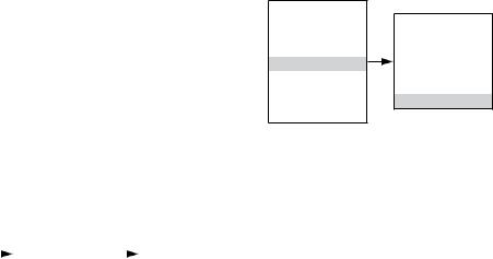
4-20 ma loOp CaliBRATION
Both the input and output current loops of the UD10 are trimmed at the factory. They can also be trimmed in the field for maximum accuracy using the following procedures. If the detector connected to the UD10 is HART enabled, its 4-20 mA output signal can also be trimmed.
When the UD10 is used with a detector that supports HART communication, the output of the detector should be calibrated first.
HART Detector Signal Calibration
Navigate down the menu to Device Test > D/A (Digital to Analog) Trim.
Main Menu |
|
|
|
|
|
|
Process Vars |
|
|
|
|
|
|
Display Status |
|
|
Device Test |
|
|
|
Device Status |
|
|
Self Test |
|
|
D/A Trim |
Display Setup |
|
|
Response Test |
|
|
Zero Trim |
|
|
|||||
Device Setup |
|
|
Loop Test |
|
|
Gain Trim |
Device Cal |
|
|
D/A Trim |
|
|
|
|
|
|
|
|
||
Display Test |
|
|
|
|
|
|
Device Test |
|
|
|
|
|
|
Select Zero Trim. When this screen is entered, a warning message is presented. Select ENTER to continue. When the message “Connect Reference Meter” is presented, install the current meter on the mA line between the detector and UD10. Select ENTER to continue. When the message “Set Input Current to 4mA?” is presented, select ENTER to begin the Zero Trim function. The detector will now set its 4 mA output value. If the value indicated on the current meter is not 4.00 mA, enter the measured value into the UD10 using the Previous and Next switches. The UD10 calculates and corrects for the difference between the actual and entered values. When the current meter value is at the desired 4.00 mA, select ENTER to accept the new zero trim value.
Select Gain Trim. Follow the same procedure for gain/ span calibration.
UD10 Input Trim
When the UD10 is used with a detector that supports HART communication, an automated process can be used to trim the UD10 input. Navigate down the menu to “Input Loop Cal”.
Main Menu
Process Vars
Display Status
Device Status
Display Setup
Device Setup
Device Cal
Display Test
Device Test
Display Setup
Alarm Setting
Mode Select
HART Option
RTC
RS485
Input Loop Cal
Upon entering Input Loop Cal, the UD10 commands the detector to output 4 mA, and then automatically calibrates its own input. The UD10 then commands the detector to output 20 mA and subsequently calibrates its own input.
If a non-HART detector is being used, the Input Loop Cal may be performed with a mA current source or loop calibrator connected to the UD10 Sensor Connector. Follow the loop calibration instructions shown by the UD10 for this procedure.
4.2 |
13 |
95-8661 |
UD10 Output Trim
To calibrate the UD10 output loop, navigate down the menu to Display Test > D/A Trim.
Main Menu |
|
|
|
|
|
|
Process Vars |
|
|
|
|
|
|
Display Status |
|
|
Display Test |
|
|
|
Device Status |
|
|
Self Test |
|
|
D/A Trim |
Display Setup |
|
|
Response Test |
|
|
Zero Trim |
|
|
|||||
Device Setup |
|
|
Loop Test |
|
|
Gain Trim |
Device Cal |
|
|
D/A Trim |
|
|
|
|
|
|
|
|
||
Display Test |
|
|
|
|
|
|
Device Test |
|
|
|
|
|
|
Select Zero Trim. When this screen is entered, a warning message is presented. Select ENTER to continue. When the message “Connect Reference Meter” is presented, install the current meter on the UD10 mA output. Select ENTER to continue. When the message “Set Output Current to 4mA?” is presented, select ENTER to begin the Zero Trim function. The UD10 will now set its 4 mA output value. If the measured value on the current meter is not 4.00 mA, enter the measured value into the UD10 using the Previous and Next switches. The UD10 calculates and corrects for the difference between the actual and entered values. When the current meter value is at the desired 4.00 mA, select ENTER to accept the new zero trim value.
Select Gain Trim. Follow the same procedure for gain/ span calibration.
OptIONAl SystEm TeSTS
The following tests are available for verifying proper operation of various functions of the gas detection system:
–The Self Test, Response Test, and Loop Test are accessed from the “Display Test” screen. (A “Device Test” screen is available for performing the same tests on HART enabled detectors.)
–The Proof Test is performed by applying test gas to the sensor. It is not accessed from the “Display Test” screen and does not inhibit the outputs.
Main Menu
Process Vars
Display Status
Device Status
Display Setup
Device Setup
Device Cal
Display Test
Device Test
Display Test
Self Test
Response Test
Loop Test
D/A Trim
Self-Test
This test commands the UD10 to perform a fully automatic internal test. At the completion of the test, the UD10 will indicate a pass or fail.
Response Test
This test inhibits the UD10’s outputs, thereby providing a means of testing the system by applying gas to the detector without activating any alarms or affecting the output.
note
If the Response Test is not terminated by the operator, the test will automatically time out after ten minutes and the UD10 will return to normal operation.
Loop Test
This test temporarily forces the UD10’s 4-20 mA output to a specific level. This is an easy way to test the output signal of the UD10 for accuracy, to verify the capabilities of the system, and to verify the input signal of a receiver. To perform this test, connect a current meter to the output loop. Navigate to Display Test and select Loop Test, then follow the prompts on the UD10 Screen.
note
If the Loop Test is not terminated by the operator, the test will automatically time out after one minute and the UD10 will return to normal operation.
Proof Test
A Proof Test (bump test) can be performed at any time to verify proper operation and calibration of the system. Since this test does not inhibit the UD10’s outputs, secure any output devices prior to performing the test to prevent unwanted actuation.
HiSTORy
There are two separate histories, one for the display and one for the detector (if available). Both will state the number of hours that the unit has been operating, and the highest and lowest recorded temperature (with time and date stamp).
4.2 |
14 |
95-8661 |

PasswoRD prOTECTION
The UD10 allows the use of a password for restricting changes to configuration parameters and limiting access to safety critical commands. The UD10 is shipped from the factory with the password protection (Write Protect) feature disabled.
The following are locked when Write Protect security is enabled:
Alarm Setting screen – All options except “RST Latch Alarms”
Mode Select screen – All options HART Option – All options
RTC – All options except Displayed Y/N
Output Mode
Display Test screen – All options
To enable the Write Protect feature, navigate to the Write Protect screen.
|
|
|
Display Setup |
|
|
|
Main Menu |
|
|
Alarm Setting |
|
|
|
Process Vars |
|
|
Mode Select |
|
|
|
|
|
HART Option |
|
|
|
|
Display Status |
|
|
|
|
Write Protect |
|
|
|
RTC |
|
|
||
Device Status |
|
|
|
|
Change State |
|
|
|
RS485 |
|
|
||
Display Setup |
|
|
|
|
Change Password |
|
|
|
Input Loop Cal |
|
|
||
Device Setup |
|
|
|
|
Write Protect xxx |
|
|
|
Contrast Contrl |
|
|
||
Device Cal |
|
|
|
|
|
|
|
|
Output Mode |
|
|
|
|
Display Test |
|
|
|
|
|
|
|
|
Backlight Ctrl |
|
|
|
|
|
|
|
|
|
|
|
|
|
|
|
|
|
|
|
|
|
|
|
|
|
|
|
|
Write Protect |
|
|
|
|
|
|
|
|
|
|
Select “Change State” to toggle between Enabled and Disabled.
Select “Change Password” to enter a new password.
“Write Protect” indicates whether password protection is Enabled or Disabled.
The default password is 1*******.
IMportant
Take care not to lose the password. Future changes cannot be made without a password.
DiSplay BaCklighT OpeRATION
The UD10 can be programmed to turn on the backlight feature of the digital display when an alarm or fault occurs or a magnetic switch is activated. Navigate to the Backlight Ctrl screen.
|
|
|
Display Setup |
|
|
|
Main Menu |
|
|
Alarm Setting |
|
|
|
Process Vars |
|
|
Mode Select |
|
|
|
Display Status |
|
|
HART Option |
|
|
|
|
|
|
|
Backlight Ctrl |
||
Device Status |
|
|
RTC |
|
|
|
|
|
|
|
Off |
||
Display Setup |
|
|
RS485 |
|
|
|
|
|
|
|
On |
||
Device Setup |
|
|
Input Loop Cal |
|
|
|
|
|
|
|
Automatic |
||
Device Cal |
|
|
Contrast Contrl |
|
|
|
|
|
|
|
|
||
Display Test |
|
|
Output Mode |
|
|
|
Device Test |
|
|
Backlight Ctrl |
|
|
|
|
|
|
Write Protect |
|
|
|
Off = The backlight is always off.
On = The backlight is always on.
Automatic = Normal operation – Backlight is off Alarm – Backlight flashes on and off Fault – Backlight is on steady
Magnetic Switch – Backlight is on steady
The backlight automatically turns off 10 minutes after the last Magnetic Switch activation.
If the backlight is on following a magnetic switch activation and then an alarm condition occurs, the backlight will remain on steady and not flash until the 10 minute time-out is complete. Then it will begin flashing.
4.2 |
15 |
95-8661 |
Troubleshooting
If a Fault condition is indicated on the UD10 faceplate, the nature of the fault can be determined by using the magnetic tool to navigate to the appropriate Fault screen.
NoTE
Refer to the Menu in the appropriate Appendix of this manual for the path to the proper Fault screen.
Shortcut: From the main display screen, touch the magnet to the “Previous” switch to go directly to the Fault screen.
Example:
For a Display (UD10) related fault:
Main Menu > Display Status > Fault/Status > Fault
For a Device (Sensor) related fault:
Main Menu > Device Status > Fault/Status > Sensor Fault
When the active fault has been identified, refer to the Troubleshooting Tables for a description of the fault and suggested corrective action.
Refer to Table 3 for Display Faults and Table 4 for Device Faults.
Table 3—Troubleshooting Guide - Display Faults
Display Faults |
Description |
Recommended Action |
|
|
|
|
|
|
|
Check sensor wiring. |
|
Input Loop FLT |
Fault in sensor or sensor loop |
Calibrate sensor. |
|
|
|
Ensure that sensor type matches configuration. |
|
|
|
|
|
Output Loop FLT |
Fault in 4-20 mA output loop |
Check 4-20 mA loop wiring for shorts or opens. |
|
|
|
|
|
EE Fault |
Fault in non-volatile memory |
Return to factory. |
|
|
|
|
|
ADC Ref Fault |
ADC reference voltage too high or low |
Return to factory. |
|
|
|
|
|
24V Fault |
Problem in 24 volt power supply or power wiring |
Check power wiring and output voltage of power |
|
supply. |
|||
|
|
||
|
|
|
|
Flash Fault |
FLASH memory Fault |
Return to factory. |
|
|
|
|
|
RAM Fault |
Fault in volatile memory |
Return to factory. |
|
|
|
|
|
WDT Fault |
Watchdog timer is non-functional |
Return to factory. |
|
|
|
|
|
12V Fault |
12 volt internal power supply out of tolerance |
Check power source. |
|
Return to factory. |
|||
|
|
||
|
|
|
|
5V Fault |
5 volt internal power supply out of tolerance |
Check power source. |
|
Return to factory. |
|||
|
|
||
|
|
|
|
3V Fault |
3 volt internal power supply out of tolerance |
Check power source. |
|
Return to factory. |
|||
|
|
||
|
|
|
Note: A fault condition will cause an oxygen detector to generate an alarm output as the decreasing 4-20 mA signal passes through the alarm range.
4.2 |
16 |
95-8661 |
Table 4—Troubleshooting Guide - Device Faults
Device Faults |
Description |
Recommended Action |
|
|
|
|
|
Loop Fault |
Current loop below fault threshold |
Check 4-20 mA loop wiring for shorts or opens. |
|
|
|
|
|
Supply Voltage |
24 volt power supply voltage too low |
Verify proper wiring to the device and correct |
|
Fault |
voltage output from the power supply. |
||
|
|||
|
|
|
|
|
|
This fault can be caused if the calibration is |
|
|
|
allowed to time out. If so, recalibrate. |
|
|
|
Ensure that there is enough gas in the calibration |
|
Calibration Fault |
Bad calibration |
bottle to complete the calibration. |
|
|
|
Ensure that the gas being used for calibration is |
|
|
|
the correct type and concentration. It must match |
|
|
|
the configured setting. |
|
|
|
|
|
Memory Fault |
Self-detected memory fault |
Return to factory. |
|
|
|
|
|
ADC Fault |
Self-detected ADC fault |
Return to factory. |
|
|
|
|
|
Internal Voltage |
Self-detected voltage fault |
Check supply voltage. |
|
Fault |
Return to factory. |
||
|
|||
|
|
|
|
|
|
Device may have been calibrated with background |
|
Zero Drift |
Sensor signal has drifted negative |
gas present. Recalibrate the detector. Purge with |
|
|
|
clean air if needed. |
|
|
|
|
|
Temperature |
Temperature sensor is out of range |
Return to factory. |
|
Sensor Fault |
|||
|
|
||
|
|
|
|
Wrong Sensor |
Wrong sensor type is installed |
Sensor type must match configuration. Change |
|
Type |
sensor or configuration. |
||
|
|||
|
|
|
|
Lamp Fault |
Open or shorted lamp |
Replace lamp. |
|
Return to factory. |
|||
|
|
||
|
|
|
|
Alignment Fault |
Open path alignment problem |
Align the device as specified in the instruction |
|
manual. |
|||
|
|
||
|
|
|
|
Blocked Optic |
Optical path is blocked |
Locate and remove obstruction from the optical |
|
Fault |
path. |
||
|
|||
|
|
|
|
Cal Line Active |
Cal line is active at start-up |
Ensure that the Cal line wiring is not shorted and |
|
the switch is open. |
|||
|
|
||
|
|
|
|
Low Cal Line |
Cal line is shorted. |
Check wiring. |
|
|
|
|
|
|
|
Check sensor wiring. |
|
Sensor Fault |
Self-detected fault with the sensor |
Calibrate sensor. |
|
|
|
Ensure that sensor type matches configuration. |
|
|
|
|
|
Noise Fault* |
Excessive noise on signal |
Check OPECL alignment. |
|
|
|
|
|
Align ADC Fault* |
Alignment ADC saturated |
Check OPECL alignment. |
|
|
|
|
|
Align Fault* |
Alignment fault |
Check OPECL alignment. |
|
|
|
|
|
Align Warning* |
Alignment warning |
Check OPECL alignment. |
|
|
|
|
|
DAC Fault |
DAC fault detected |
Return to factory. |
|
|
|
|
|
General Fault |
Unspecified fault |
Verify correct power wiring and supply voltage. |
|
Consult the factory. |
|||
|
|
||
|
|
|
|
High Fault |
Detector output is higher than specified limit |
Verify correct sensor type and calibration. |
|
|
|
|
|
Low Fault |
Detector output is lower than specified limit |
Verify correct sensor type and calibration. |
|
|
|
|
|
Dirty Optics |
Detector optics are dirty |
Perform the cleaning procedure as described in |
|
the detector manual, then perform calibration. |
|||
|
|
||
|
|
|
|
Start Cal Fault |
Calibration fault |
Verify correct sensor type and calibrate. |
|
|
|
|
|
*OPECL only. |
|
|
4.2 |
17 |
95-8661 |
Table 4—Troubleshooting Guide - Device Faults, Continued
Device Faults |
Description |
Recommended Action |
|
|
|
|
|
|
|
Power may have been interrupted while the device |
|
EE Fault |
Fault in non-volatile memory |
was updating its internal data logs. Recycle |
|
|
|
power. |
|
|
|
|
|
Ref ADC Sat |
Sensor signal level is outside the range of the AD |
Return to factory. |
|
converter |
|||
|
|
||
|
|
|
|
Active ADC Sat |
Sensor signal level is outside the range of the AD |
Return to factory. |
|
converter |
|||
|
|
||
|
|
|
|
24V Fault |
Problem in 24 volt power supply or power wiring |
Check power wiring and output voltage of power |
|
supply. |
|||
|
|
||
|
|
|
|
Flash CRC Fault |
Memory fault |
Return to factory. |
|
|
|
|
|
RAM Fault |
Fault in volatile memory |
Return to factory. |
|
|
|
|
|
Low Voltage |
Power supply voltage outside of limits |
Check power supply voltage. |
|
Return to factory. |
|||
|
|
||
|
|
|
|
Temp Fault |
Temperature sensor fault |
Return to factory. |
|
|
|
|
|
Software Fault |
Internal software fault |
Return to factory. |
|
|
|
|
|
EE Safety Fault |
Internal configuration fault |
Return to factory. |
|
|
|
|
|
|
|
Device may have been calibrated with background |
|
Gas Under Range |
Sensor signal has drifted negative |
gas present. Recalibrate the detector. Purge with |
|
|
|
clean air if needed. |
|
|
|
|
|
Sensor Mismatch |
Wrong sensor type is installed |
Sensor type must match configuration. Change |
|
sensor or configuration. |
|||
|
|
||
|
|
|
|
ADC CNTR Fault |
Internal hardware fault |
Return to factory. |
|
|
|
|
|
3V Fault |
3 volt internal power supply out of tolerance |
Return to factory. |
|
|
|
|
|
Comm Fault |
Communication fault |
Check detector wiring and power supply. |
|
|
|
|
|
GEN Fault |
Unspecified fault |
Verify correct power wiring and supply voltage. |
|
Consult the factory. |
|||
|
|
||
|
|
|
|
12V Fault |
12 volt internal power supply out of tolerance |
Return to factory. |
|
|
|
|
|
5V Fault |
5 volt internal power supply out of tolerance |
Return to factory. |
|
|
|
|
4.2 |
18 |
95-8661 |
Specifications
operating voltAGE—
24 Vdc nominal, operating range is 18 to 30 Vdc. Ripple cannot exceed 0.5 volt P-P.
operating power—
Standard model, with heater and backlight off:
No alarm: |
1.5 watts @ 24 Vdc. |
Alarm: |
3 watts @ 24 Vdc (20 mA current |
|
loop output, and all 3 alarm relays |
|
energized.) |
Backlight on: |
0.5 watt additional. |
Heater on: |
3.5 watts additional. |
CGS model: |
Add 4 watts with CGS interface |
|
board and CGS sensor installed. |
Maximum power in alarm, with heater and backlight on: 7 watts @ 30 Vdc (Standard model) 11 watts @ 30 Vdc (CGS model)
note
Heater turns on when the internal temperature drops below –10°C (default operation). Heater function can be disabled to save power.
note
Appropriate relays will be activated when a fault or alarm occurs.
CURRENT OUTPUT—
Linear isolated 4-20 mA output with HART. 3.8 mA indicates calibrate mode.
3.6 mA or less indicates a fault condition.
Maximum loop resistance is 600 ohms at 18 to 30 Vdc.
CURRENT OUTPUT Response Time—
Toxic gas mode: |
T90 |
≤5 seconds. |
Combustible gas mode: |
T90 |
≤4 seconds. |
Combustible gas - open path mode: T90 |
≤4 seconds. |
|
UD10 with CGS: |
T90 |
<12 seconds. |
Current Output AccuraCy— |
|
|
Toxic gas mode: |
<1% error. |
|
Combustible gas mode: |
<1% error. |
|
Combustible gas - open path mode: ≤0.01 LFL-m. |
||
UD10 with CGS: |
±3% LFL 0-50 range, |
|
|
±5% LFL 51-100 range. |
|
RELAY CONTACTS—
Three Alarm Relays: Form C, 5 amperes at 30 Vdc. Selectable energized/de-energized. Selectable latching or non latching. Refer to Table 1 for range and default settings.
Warning
When in non-latching mode, the control device must latch the alarm output.
One Fault Relay: |
Form C, 5 amperes at 30 Vdc. |
|
Normally energized for no fault |
|
condition with power applied. |
Relay Response Time—
≤ 2 seconds.
Wiring terminals—
14 to 18 AWG wire can be used.
OPERATing temperature—
–55°C to +75°C.
StorAGE TeMPERATURE—
–55°C to +75°C.
HuMidity Range—
5 to 95% RH (Det-Tronics verified).
electro-magnetic compatibility—
EMC Directive 2004/108/EC EN55011 (Emissions) EN50270 (Immunity)
DIMENSIONS—
See Figures 12 and 13.
4.2 |
19 |
95-8661 |

6.48 |
4.7 |
(16.5) |
(11.9) |
|
3.46 |
|
(8.8) |
|
5.2 |
|
(13.2) |
|
5.86 |
|
(14.9) |
11.28 |
|
(28.7) |
|
|
R0.175 |
A2442
Figure 12—Dimensions of UD10 with GT3000 in Inches (Centimeters)
CondUit EntRies— |
WARRANTY— |
|
3/4” NPT or M25. |
12 months from date of installation or 18 months from |
|
|
|
date of shipment, whichever occurs first. |
ENCLOSURE MATERIAL— |
|
|
Epoxy coated aluminum or 316 stainless steel. |
Detector compatibility— |
|
|
|
The UD10 can be used with the Det Tronics gas |
SHIPPInG WEIGHT— |
detectors listed in Table 5. |
|
Aluminum: |
4.15 pounds (1.88 kilograms). |
|
Stainless steel: |
10.5 pounds (4.76 kilograms). |
Unit of Measurement— |
|
|
PPM, % LFL, % V/V, LFL-m, or mg/m3. |
4.2 |
20 |
95-8661 |

4.7
(11.9)
3.46
(8.8)
3.77
(9.6)
1.28
(3.3)
5.86
(14.9)
5.2
(13.2)
2.7
(6.9)
Certification—
For complete approval details, refer to the appropriate Appendix:
FM |
® |
APPROVED |
|
Appendix A – FM
Appendix B – CSA
Appendix C – ATEX
Appendix D – IECEx
Appendix E – INMETRO
SIL Approval - IEC 61508
Certified SIL 2 Capable.
For specific information regarding SIL safety certification, refer to the Model UD10 Safety Reference Manual (form 95-8668).
C2281
Figure 13—Dimensions of Model STB Termination Box in Inches (Centimeters)
Table 5—Gas Detectors Compatible with the UD10
Device |
Toxic1 |
Catalytic |
IR2 |
Instruction |
|
Combustible |
Combustible |
Manual |
|||
|
|
||||
|
|
|
|
|
|
GT3000 |
X |
|
|
95-8616 |
|
|
|
|
|
|
|
PIR9400 |
|
|
X |
95-8440 |
|
|
|
|
|
|
|
PIRECL |
|
|
X |
95-8526 |
|
|
|
|
|
|
|
OPECL |
|
|
X |
95-8556 |
|
|
|
|
|
|
|
CGS |
|
X |
|
90-1041 |
|
|
|
|
|
|
|
505/CGS |
|
X |
|
95-8472 |
|
|
|
|
|
|
|
|
|
|
|
95-8396 |
|
C706X3 |
X |
|
|
95-8411 |
|
|
|
95-8414 |
|||
|
|
|
|
||
|
|
|
|
95-8439 |
|
|
|
|
|
|
|
NTMOS4 |
X |
|
|
95-8604 |
1Hydrogen sulfide, Ammonia, Chlorine, Hydrogen, Oxygen, Carbon Monoxide, and Sulfur Dioxide.
2Methane, Ethane, Ethylene, Propane, and Propylene.
3C7065E Oxygen detector is not supported.
4Hydrogen sulfide only.
4.2 |
21 |
95-8661 |
DEVICE REPAIR AND RETURN
Prior to returning devices, contact the nearest local Detector Electronics office so that a Return Material Identification (RMI) number can be assigned. A written statement describing the malfunction must accompany the returned device or component to assist and expedite finding the root cause of the failure.
Pack the unit properly. Always use sufficient packing material. Where applicable, use an antistatic bag as protection from electrostatic discharge. The RMI number should be clearly marked on the outside of the box.
note
Inadequate packaging that ultimately causes damage to the returned device during shipment will result in a service charge to repair the damage incurred during shipment.
Return all equipment transportation prepaid to the factory in Minneapolis.
NoTE
It is highly recommended that a spare be kept on hand for field replacement to ensure continuous protection.
ORDERING INFORMATion
Sensor module, transmitter module and termination boxes (if used) must be ordered separately.
Refer to the UD10 Model Matrix for ordering details.
aCCESSORIES
Part Number |
Description |
009700-001 |
Magnetic Tool |
103922-001 |
475 Field Communicator |
010268-001 |
Gas Inspector CD |
010204-001 |
W6300G1003 Gas Inspector Connector |
005003-001 |
Lubriplate grease, 1 oz. |
101197-001* |
Stop Plug, 3/4” NPT, AL |
101197-004* |
Stop Plug, 3/4” NPT, SS |
101197-005 |
Stop Plug, M25, AL, IP66 |
101197-003 |
Stop Plug, M25, SS, IP66 |
010816-001 |
Stop Plug, 20PK, 3/4” NPT, AL |
010817-001 |
Stop Plug, 20PK, 3/4” NPT, SS |
010818-001 |
Stop Plug, 20PK, M25, AL, IP66, EXDE |
010819-001 |
Stop Plug, 20PK, M25, SS, IP66, EXDE |
104190-001 |
Stop Plug, M25, AL, INMETRO |
104190-002 |
Stop Plug, 3/4” NPT, AL, INMETRO |
104190-003 |
Stop Plug, M25, SS, INMETRO |
104190-004 |
Stop Plug, 3/4” NPT, SS, INMETRO |
102804-001 |
Reducer, M25 to M20, AL |
102804-003 |
Reducer, M25 to M20, SS |
*NEMA/Type 4X, IP66 rating requires addition of Teflon tape.
ReplaCEmeNT Parts
Part Number Description
010569-001 Electronics Module - Relay/4-20 mA
010550-001 Electronics Module - Foundation Fieldbus
AsSISTANCE
For assistance in ordering a system to meet the needs of a specific application, please contact:
Detector Electronics Corporation 6901 West 110th Street
Minneapolis, Minnesota 55438 USA Operator: (952) 941-5665 or (800) 765-FIRE Customer Service: (952) 946-6491
Fax: (952) 829-8750
Web site: www.det-tronics.com E-mail: det-tronics@det-tronics.com
4.2 |
22 |
95-8661 |
 Loading...