


 Loading...
To navigate through this document, click on the “Bookmarks and Page” button and use the bookmarks to access information.
INSTRUCTIONS
Ultraviolet Flame Detection System
R7404 Controller
C7050 Detector
|
|
7/97 |
Form 95-8242-04 |
Table of Contents
SYSTEM APPLICATION ..................................................... |
1 |
FEATURES ......................................................................... |
2 |
GENERAL APPLICATION INFORMATION ......................... |
2 |
SYSTEM DESCRIPTION ................................................... |
2 |
Detector ......................................................................... |
3 |
Controller ....................................................................... |
3 |
SPECIFICATIONS .............................................................. |
5 |
DETECTOR SENSITIVITY ................................................. |
6 |
SYSTEM SENSITIVITY CONSIDERATIONS ..................... |
8 |
INSTALLATION ................................................................. |
10 |
Wiring Requirements ................................................... |
10 |
Detector Positioning and Density ................................ |
11 |
Mounting the Detector ................................................. |
11 |
Controller ..................................................................... |
13 |
TYPICAL SYSTEM APPLICATIONS ................................ |
17 |
STARTUP PROCEDURE .................................................. |
21 |
CHECKOUT PROCEDURE .............................................. |
21 |
Manual oi Check ......................................................... |
21 |
Detector Count Test ..................................................... |
21 |
Manual Check in Normal Mode ................................... |
22 |
MAINTENANCE ................................................................ |
23 |
TROUBLESHOOTING ...................................................... |
23 |
DEVICE REPAIR AND RETURN ...................................... |
23 |
ORDERING INFORMATION ............................................. |
25 |
Options ........................................................................ |
26 |
Recommended Spare Parts ........................................ |
26 |
INSTRUCTIONS
Ultraviolet Flame Detection System
R7404 Controller
C7050 Detector
SYSTEM APPLICATION
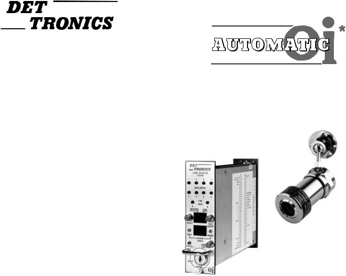
The Det-Tronics model R7404 Controller and C7050 Detector provide fast, reliable flame detection in a wide variety of applications. The microprocessor based controller simultaneously monitors up to 16 C7050 ultraviolet (UV) detectors in up to 8 different zones. The system uses the Automatic Optical Integrity (oi) feature, which provides a continuous check of detector optical surfaces, detector sensitivity, and electronic circuitry of the detector/controller system. Also included is automatic fault identification, which monitors the system for proper operation, and provides a digital display of system status using a numerical code. Other features include individual zone identification and “voting” capability, as well as manual oi testing.
The C7050 Detector responds instantly to the ultraviolet radiation that is emitted by a flame. It is designed for use in hazardous locations and is particularly suitable for use in outdoor applications because it is not affected by wind or rain, and is insensitive to solar radiation. In addition, the detector does not respond to normal artificial light.
Typical applications for Det-Tronics UV detection systems are:
—Wherever highly combustible materials are involved
—Where there is a need for instantaneous response to flame
—Wherever unsupervised areas require automated fire protection
—Where there is a large capital investment to be protected.
*oi is Detector Electronics' Trademark for its patented Optical Integrity Systems, U.S. Patent 3,952,196, United Kingdom Patent 1,534,969, Canada Patent 1,059,598.
Examples of actual installations using the Det-Tronics UV detector in automated fire protection systems include:
Petroleum Products
—Gasoline transport loading terminals
—Offshore drilling and production platforms
—Pipeline pumping stations
—Tank farms
—Refineries
—Marine engine rooms
—Jet engine test cells
Gaseous Fuels
—Butane and propane loading and storage
—Pipeline compressor stations
—Gas gathering facilities
—Pipelines in highly populated areas
—LNG loading, transfer and storage facilities
—Hydrogen and ammonia production and refinery reformers
—Gas turbines
© Detector Electronics Corporation 1997 |
07/97 |
95-8242-04 |
Solid Materials
—Munitions production such as illuminating flare material, TNT, and other propellants
—Powder coating booths
Other Processes
—Paint Spray booths
—Chemical and Petrochemical production
Information on these and a wide variety of applications is available from Detector Electronics.
FEATURES
•Instantaneous response to ultraviolet radiation.
•Detectors operate under adverse weather conditions such as wind, rain, snow, high humidity, and extremes of temperature or pressure.
•Automatic Optical Integrity.
•Adjustable sensitivity and time delay.
•All automatic test functions performed with the system on line.
•Manual oi test capability (in addition to Automatic oi capability).
•Automatic fault identification.
•Individual zone identification with eight voting options.
•Microprocessor control.
•Latching ZONE LEDs identify the zone responding to fire.
•Output circuits can be made latching or non-latching through field adjustment.
•Individual detector output (count rate) can be measured and observed on the digital display.
•Digital display of background UV signals in Test mode.
•Digital display signal output available at field wiring terminals for interfacing with computers or other equipment.
•Detector is Factory Mutual (FM) approved, Canadian Standards Association (CSA) certified, and BASEEFA/CENELEC certified.
such as wind, rain, or extremes of temperature and pressure. The Det-Tronics UV system is also insensitive to the ultraviolet component of solar radiation.
Considering the above, it can be seen that there are fire detection applications where only ultraviolet sensors are suitable. However, success in using an ultraviolet detector is dependent not only on knowing its advantages, but also its limitations. It is important to note that electric arc welding is a source of intense ultraviolet radiation, and care must be taken to ensure that arc welding is not performed in protected areas without securing the system. In addition, UV detectors should not be positioned so that their cone of vision can scan the horizon. Rather, they should be directed down over the designated hazardous area to reduce the likelihood of picking up UV radiation from distant sources.
An important fact regarding radiation detectors of any type is that the radiation must reach the detectors in order for them to respond. Care must be taken to keep obstructions out of the line of view. For an ultraviolet detector, this means that ultraviolet absorbing gases or vapors as well as physical obstructions must not be allowed to come between the detector and the protected hazard. Smoke will absorb ultraviolet radiation, and if accumulations of dense smoke can be expected to precede the presence of flame, then UV detectors that are used in enclosed areas should be mounted on the wall approximately 3 feet (1 meter) from the ceiling where the accumulation of smoke is reduced. Glass and plexiglass windows also significantly attenuate UV radiation and must not be located between the detector and a potential flame source. If the window cannot be eliminated or the detector location changed, contact Detector Electronics for recommendations regarding window materials that will not attenuate UV radiation.
It must be noted that malfunctions can occur in any type of equipment, and although Det-Tronics systems are subjected to rigorous tests before shipment, no way has yet been found to guarantee that every device will always operate perfectly. The highest reliability with regard to response to a fire is achieved when a hazardous area is supervised by more than one detector, and when each detector can independently register an alarm.
GENERAL APPLICATION INFORMATION
In applying any type of sensing device as a fire detector, it is important to know of any conditions that may prevent the device from responding to a fire, and also to know what other sources besides fire will cause the device to respond. A UV detector is useful in fire protection applications because it will provide very fast response to the presence of ultraviolet radiation emitted by a flame. In addition, it is not affected by environmental conditions
SYSTEM DESCRIPTION
The R7404/C7050 UV detection system consists of an R7404 Controller and up to 16 C7050 Detectors.
DETECTOR
The C7050 Detector responds to UV radiation over the range of 1850 to 2450 angstroms. It is insensitive to direct or reflected sunlight and to normal artificial lighting.
2
The output of the detector consists of a series of voltage pulses or “counts.” The frequency of these pulses is directly proportional to the intensity of the radiation being detected and is measured in counts per second (cps).
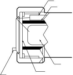
oi
The detector is equipped with the Automatic oi feature (Figure 1). A UV test lamp is mounted in the same enclosure with the UV sensor tube, but they are optically isolated from each other by a cylindrical shield. When the test lamp is actuated by a signal from the controller, it generates a UV test signal that travels out through the viewing window, where it encounters the reflective oi ring and is directed back through the window to the sensor. The controller evaluates the strength of the return signal to determine the relative condition of the detector and its optical surfaces. Since this UV test signal must pass through the same portion of the viewing window as UV radiation generated by a flame, a reliable test of the ability of the detector to “see” a fire is achieved.
The controller continuously executes the automatic oi test, sequentially testing each detector connected to it. If a fault should occur in the system, it is quickly detected and registered on the digital display on the front panel of the controller and the Fault output is de-ener- gized.
Internal Reflection oi
The use of an Internal Reflection oi detector is recommended in applications where corrosive or oily contaminants are present in the atmosphere. This type of environment can cause rapid deterioration of the reflectivity of externally mounted oi rings, resulting in the need for frequent detector maintenance. Since the Internal Reflection detector checks the cleanliness of the viewing window without the use of an external reflective oi ring, faults caused by corrosion or contamination of the ring are eliminated. A fault will be indicated only if the viewing window is actually dirty. It is important to note that the internal reflection system is effective only with oily substances that wet the surface of the window. It does not detect dry contaminants and, therefore, is not practical for powder coating booths or similar applications where various dry contaminants can obscure the vision of the detector.
UV detectors that are currently using the external reflection oi system can easily be converted to Internal Reflection in the field by simply replacing the existing sensor tube module with a DE1888V Internal Reflection oi Tube Module. No calibration or other adjustments are required, and no modifications to the detector enclosure are needed.
Detector Enclosure
The detector is housed in an explosion-proof enclosure that is designed to meet most national and international standards. It is available in various materials to meet the requirements of the environment in which it is used. Materials include anodized aluminum, nickel-plated brass and 316 stainless steel. The aluminum and the nickel-plated brass housings are epoxy coated, making them suitable for use in high saline atmospheres, such as offshore platforms.
The detector is typically mounted on an optional swivel mounting assembly (Model Q9001), which is recommended for ease in installation. Other mounting arrangements are also available, such as a quickconnect front mount for applications involving paint spray or powder coating booths, or for looking inside mixers, kettles, conveyors and other inaccessible areas.
CONTROLLER
The R7404 is designed for use with 24 volt dc power supplies, but will operate from any direct current supply between 10 and 38 volts. The unit will tolerate transients such as those that can occur when fully discharged batteries are placed on charge. When power is present at the R7404 Controller, it is indicated by a continuously energized green LED. All other lights and displays on the R7404 panel are normally off, but may be periodically checked for operation by pressing the LAMP TEST button located directly opposite the POWER light as illustrated in Figure 2. It is not necessary for the controller to be in the TEST mode when this check is performed.
The R7404 Controller incorporates a microprocessor and a programmable-read-only-memory (PROM) to store and implement the permanent program for operating the sys-
UV TEST LAMP
OPTICAL SHIELD
UV DETECTOR
UV SENSOR
|
VIEWING WINDOW |
SNAP-IN oi RING |
C784 |
Figure 1—Detector with oi
3 |
95-8242 |

tem. The main loop of the operating program continuously cycles through the Automatic Optical Integrity test, checking each detector and its wiring. At the same time, the microprocessor can be interrupted by any one of several status changes, such as a fault, a “fire” signal from one of the detection zones, or a change in the setting of the keylock switch. In the event of a status change, the microprocessor will take the appropriate action.
NOTE
The R7404 is available with various optional operating programs (STAR Logic, Remote Surveillance, etc.). This manual covers the operation of the R7404 with the standard program. Always refer to the manual supplied with any special purpose controllers when operating or installing the equipment.
Fire Response
When the controller receives a “fire” signal from any detector in the system, it is compared to the stored information of the program. If the signal frequency is lower than the programmed setting for sensitivity, the lower display on the front panel of the controller responds with a “3” and the upper display identifies the first zone affected. If the signal frequency is greater than the programmed sensitivity setting for a period greater than the preset time delay, the following actions take place:
1.The appropriate solid state zone output(s) is energized. One zone output is available for each of the eight zones.
|
RED LEDS |
|
RED LEDS |
DETECTOR SELECTION |
TEST/ACCEPT |
AMBER LED |
AMBER LED |
GREEN LED |
LAMP TEST |
|
 KEYLOCK SWITCH
E0235
Figure 2—Front Panel of R7404
2.The solid state alarm output is energized. The alarm output is activated when any zone detects a fire.
3.The ZONE display identifies the first responding zone. The DETECTOR display is blank.
4.The SYSTEM STATUS display shows a “6”, indicating fire.
5.One or more ZONE LEDs turn on (blinking), indicating the zone(s) detecting UV radiation.
6.If the selected “voting” criteria has been satisfied, the appropriate Fire Logic output is energized, and the corresponding LED is on.
NOTE
When a fire signal is no longer present, the ZONE LED(s) and the display indication will latch until manually reset (ZONE LED emits steady light). The display latch feature is useful in post-fire analysis as a means of determining fire origin.
The Alarm output is typically used to actuate an external audible alarm when a fire signal is received from one or more detectors. Since these alarms can be disruptive to personnel who are responding to the fire emergency, a means for alarm silencing has been provided. The R7404 is equipped with a TEST/ACCEPT button, which will de-activate the alarm circuit without interrupting the Zone and Fire Logic outputs. The alarm can also be silenced by an optional external silence switch (see “Typical Applications” section).
NOTE
If the system is going to be put out of service for periods of time, use the Test/accept to bypass the alarm contacts instead of shutting down the system. This will provide optimum performance when reconnected.
Digital Displays
The upper digital display on the R7404 panel identifies both the detector and zone involved in any “System Status” occurrence. For example, with the keylock switch in the TEST position, and a “1” digit showing on the lower display, the upper display shows which detector and zone is electrically positioned for a manual oi test.
Voting Logic
The R7404 permits two groups of four zones each to “vote” separately, or eight zones to “vote” together. This means that the controller can be programmed to require more than one detector to be actuated before the Fire Logic A and/or B outputs are energized. The DetTronics “voting” principle allows combinations of detec-
4

tors to fulfill voting requirements, and represents the best balance between reliability of fire detection and freedom from false actuation due to individual detector malfunction.
Fault Identification
The automatic fault identification feature of the R7404 operates much the same as on other Det-Tronics equipment, but has expanded capability. The lower display on the controller panel identifies the probable source or type of fault using a numerical code. A summary of the R7404 system status code is shown in Table 1.
System Reset
The reset function is incorporated in a rotary keylock switch, which has three positions: (1) NORMAL, (2) RESET and (3) TEST. The switch sequence is such that a return to NORMAL from the TEST position can be achieved only by passing through the RESET mode (Figure 2). The reset function may also be performed by an optional external reset switch. Whenever the keylock switch is placed in the RESET or TEST position, the FAULT and INHIBIT LEDs will turn on, and all Zone, Fire Logic, and Alarm outputs will be disabled.
Programming Switches
The circuit board on the left side of the R7404 Controller contains switches for selection of:
1.Detectors connected to the controller
2.System sensitivity
3.Time delay
4.Fire logic and latching/non-latching options.
See “Switch Setting Procedure” in the “Installation” section for a detailed description.
Table 1—System Status Codes
0 — Keylock switch in RESET position, or external Inhibit/Reset is activated.
1 — Keylock switch in TEST position.
2 — Reduced detector sensitivity ( oi fault) or faulty wiring.
3 — Spurious UV detection or over sensitive detector.
4 — Low +290 vdc
(+290 volt detector supply wire may be shorted).
5 — High +290 vdc
(voltage regulation failure in the 290 volt supply).
6 — Fire.
7 — Not used.
8 — Controller in count test mode.
SPECIFICATIONS
SPECTRAL SENSITIVITY RANGE—
The detector responds to UV radiation over the range of 185 to 245 nanometers (1850 to 2450 angstroms).
SYSTEM SENSITIVITY—
Sensitivity for the standard R7404 Controller is field adjustable over a range of 8 through 120 counts per second (cps) in increments of 8 cps. The maximum response distance is achieved at an 8 cps sensitivity setting. For applications involving high background radiation potential, the system can be desensitized by increasing the count rate required to actuate it. The 120 cps setting results in the minimum response distance.
INPUT VOLTAGE—
The R7404 can operate from any voltage in the range of 18 to 38 volts dc.
TEMPERATURE RATING—
Operating: |
|
Standard detector: |
–40°F to +167°F (–40°C to +75°C). |
Controller: |
–40°F to +167°F (–40°C to +75°C). |
Detectors with higher temperature ratings are available.
Storage:
Detector and controller:
–67°F to +167°F (–55°C to +75°C).
HUMIDITY—
0 to 95% RH, non-condensing.
RESPONSE TIME—
Response to a saturating (high intensity) UV source is typically 10 milliseconds for the zone and alarm outputs and 150 milliseconds for the fire logic outputs when sensitivity is set for 8 cps and time delay is set for 0 seconds.
OUTPUT CIRCUIT RATINGS—
Open collector solid state output is rated 100 milliamperes dc at 60 volts dc. Lead monitoring is provided by an internal 100 kilohm resistor from output to ground. External equipment that can generate transients when switching (such as relays) must have a transient suppression device (diode) connected across the coil at the time of installation to safeguard the output transistors against possible damage. See the “Installation” section for details.
POWER CONSUMPTION (Controller and 16 Detectors)—
Standby: |
1.5 watts typical, 1.7 watts maximum. |
Fire: |
15 watts typical, 16.5 watts maximum. |
WIRING REQUIREMENTS—
The detector wiring must be a minimum of 22 gauge with a minimum voltage rating of 600 volts rms. (22 gauge copper wire has a diameter of 0.6439 mm or 0.02535 inch. Its cross section is 0.3255 mm2 or 0.0005 in2. Its
5 |
95-8242 |

resistance is 16.14 ohm/1000 ft. or 53.0 ohm/km.) The R7404 Controller will accommodate up to 16 detectors. The detectors can be located up to 2000 feet (600 meters) from the controller. Shielded cable is required for the “B” (signal) leadwires. As with any field device, shielded cable on all wires provides maximum protection from RFI/EMI sources.
SHIPPING WEIGHT (Approximate)— |
|
|
|
Pounds |
Kilograms |
Controller |
2.5 |
1.12 |
Detector (aluminum) |
1.25 |
0.56 |
(stainless steel or brass) |
2.25 |
1.0 |
DIMENSIONS—
Refer to Figure 3 for dimensions of the controller and Figure 4 for the detector and swivel mounting brackets. Figure 5 shows the dimensions of the Q4004 Mounting Cage. Cages that hold fewer devices are also available.
CONE OF VISION—
The C7050 Detector has a nominal 90 degree cone of vision with the highest sensitivity along its central axis. See Figure 7.
DETECTOR ENCLOSURE MATERIALS—
Models are available in anodized copper-free aluminum, nickel-plated brass, or 316 stainless steel.
CERTIFICATIONS— |
|
|
|
FMRC: |
See Appendix A for details. |
||
CSA: |
Explosion-proof for Class I, Division 1, |
||
|
Groups C and D. |
|
|
|
Dust ignition-proof for Class II, Division 1, |
||
|
Groups E, F, and G. |
|
|
|
Enclosure Type 4 (Indoor and Outdoor |
||
|
Use) |
|
|
CSFM: |
Explosion-proof for Class I, Division 1, |
||
|
Groups B, C and D. |
|
|
|
Dust ignition-proof for Class II, Division 1, |
||
|
Groups E, F, and G. |
|
|
CENELEC: |
EEx d IIB+H2 |
T6 (T |
= –40°C to +77°C) |
|
EEx d IIB+H2 |
amb |
= –40°C to +125°C) |
|
T4 (T |
||
|
|
amb |
|
|
IP66 |
|
|
|
Special Conditions for Safe Use “X”: |
||
|
The fused silica window is liable to be |
||
|
damaged by impact. The detector should |
||
|
be installed in such a manner as to pre- |
||
|
vent the window from receiving mechani- |
||
|
cal damage. |
|
|
Russian |
Performance Verified from –55°C to +75°C |
||
Certification: |
1Ex d IIB T6X (T = –40°C to +77°C) |
||
|
|
amb |
= –40°C to +125°C) |
|
1Ex d IIB T4/H2 X (T |
||
|
|
amb |
|
|
IP66 |
|
|
9.5 (242 MM) |
|
|
|
|
|
|
|
2.0 |
|
|
|
|
|
|
|
|
(50MM) |
||
|
|
|
|
|
|
|
|
|
|
7.0
(177 MM)
F234
Figure 3—Controller Dimensions in Inches (Millimeters)
Q9001H – USE FOR MOUNTING NICKEL/BRASS
AND STAINLESS STEEL C7050 DETECTORS
3/4 INCH NUT USED TO SECURE DETECTOR TO SWIVEL MOUNT
1/2 INCH NUT USED TO ADJUST ELBOW TO DESIRED ANGLE
5-1/4 INCHES
(133 MM)
1-3/8 INCH NUT USED TO ROTATE  SWIVEL/DETECTOR ASSEMBLY TO DESIRED POSITION
MOUNTING BASE |
|
|
|
|
|
|
|
|
|
|
|
|
|
|
|
|
|
|
|
|
|
|
|
|
|
|
|
|
|
|
|
|
|
2-1/2 INCHES |
|
|
|||
|
|
|
|
|
|
|
|
|
|
|
|
|
|
(64 MM) |
|
|
|
B1323 |
|
|
|
|
|
|
|
|
|||||||||||||
2-1/2 (64 MM) DIAMETER |
|
|
|
|
|
|
|||||||||||||
|
|
|
|
|
|
|
|
|
|
|
|
|
|
||||||
|
|
|
|
|
|
|
|
|
|
|
120o ± 2o (2) |
|
|
|
|||||
|
|
|
|
|
|
|
|
|
|
|
|
|
|
|
|
|
|
|
|
|
|
|
|
|
|
|
|
|
|
|
|
|
|
|
|
|
|
|
|
|
|
|
|
|
|
|
|
|
|
|
|
|
|
|
|
|
|
|
|
0.25 (6.4 MM) DIAMETER (3)
2.00 (50.8 MM) DIAMETER
|
OPTIONAL SWIVEL |
|
|
MOUNTING BRACKET |
|
2-1/2 |
(Q9001B, FOR ALUMINUM ONLY) |
|
(64 MM) |
|
|
|
POSITIONING SWIVEL NUT |
|
DETECTOR LOCK NUT |
45o (2) |
|
|
||
5/16 – 18 UNC – 2A |
|
|
CONDUIT OPTIONS: |
TERMINAL CAP |
|
1/2 – 14 NPT |
|
|
3/4 – 14 NPT |
|
|
M20 x 1.5 |
DETECTOR HOUSING |
|
M25 x 1.5 – 6H |
||
|
||
Pg 16 |
|
4-3/4
(121 MM)
2-1/2
(64 MM)
G0121
Figure 4—Detector Dimensions in Inches (Millimeters)
6

PART NUMBER |
CONTROLLER |
|
|
|
|
|
|
|
|
|
|
|
|
|
|
|
|
|
|
005269-XXX |
POSITIONS FOR: |
HT: |
DIM. (A) |
DIM. (B) |
DIM. (C) |
DIM. (D) |
DIM. (E) |
WEIGHT |
|||||||||||
|
FIRE |
GAS |
|
INCH |
MM |
INCH |
MM |
INCH |
MM |
INCH |
MM |
INCH |
MM |
LB |
KG |
||||
|
|
|
|
|
|
|
|
|
|
|
|
|
|
|
|
|
|
|
|
–001 |
8 |
16 |
4U |
19.00 |
482.6 |
18.30 |
464.8 |
17.36 |
440.9 |
4.00 |
101.6 |
6.97 |
177.1 |
9.3 |
4.2 |
||||
–002 |
6 |
12 |
4U |
15.06 |
382.6 |
14.36 |
364.7 |
13.42 |
340.9 |
|
|
|
|
|
|
|
|
7.6 |
3.5 |
|
|
|
|
|
|
|
|
||||||||||||
–003 |
4 |
8 |
4U |
11.13 |
282.6 |
10.43 |
264.9 |
9.49 |
241.1 |
|
|
|
|
|
|
|
|
5.9 |
2.7 |
–004 |
3 |
6 |
4U |
9.16 |
232.7 |
8.46 |
214.9 |
7.52 |
191.0 |
|
|
|
|
|
|
|
|
5.1 |
2.3 |
–005 |
2 |
4 |
4U |
7.19 |
182.7 |
6.49 |
164.9 |
5.55 |
141.0 |
|
|
|
|
|
|
|
|
4.2 |
1.9 |
–006 |
1 |
2 |
4U |
5.22 |
132.6 |
4.52 |
114.8 |
3.58 |
90.9 |
|
|
|
|
|
|
|
|
3.1 |
1.4 |
(A)
(B)
(C)
1.48 (37.59)
(D)
(E)
ALL CONTROLLER CAGES REQUIRE
A MINIMUM OF 10.12 INCHES (257.1 MM)
DEPTH CLEARANCE
B1475
Figure 5—Q4004 Mounting Cage Dimensions in Inches (Millimeters)
|
|
ULTRAVIOLET |
|
|
VISIBLE |
|
|
|
|
|
INFRARED |
|
|
|
|
|
100 |
|
|
|
|
|
|
|
|
|
|
|
|
|
|
|
75 |
|
|
|
|
|
|
|
|
|
|
|
|
|
|
ATMOSPHERIC |
50 |
|
|
|
|
|
|
|
|
|
|
|
|
|
|
TRANSMISSION |
|
|
|
|
|
|
|
|
|
|
|
|
|
|
|
|
|
|
|
|
|
|
|
|
|
|
|
|
|
|
|
|
25 |
|
|
|
|
|
|
|
|
|
|
|
|
|
|
|
0 |
|
|
|
|
|
|
|
|
|
|
|
|
|
|
|
0.1 |
0.2 |
0.3 |
0.4 |
0.5 |
0.6 |
0.7 |
0.8 |
0.9 |
1.0 |
1.5 |
2.0 |
3.0 |
4.0 |
5.0 |
|
|
|
|
|
WAVELENGTH (MICRONS) |
|
|
|
|
|
|||||
ULTRAVIOLET SENSOR RESPONSE |
SOLAR RADIATION REACHING THE EARTH |
A1898 |
Figure 6—Detector Range of Sensitivity
DETECTOR SENSITIVITY
The UV flame detector responds to radiation over wavelengths of 185 to 245 nanometers (1850 to 2450 angstroms). Figure 6 illustrates the range of sensitivity, and compares this range to other forms of radiation. Note that UV radiation reaching the earth from the sun does not extend into the region of sensitivity of the detector. In addition, radiation from normal artificial lighting, such as fluorescent, mercury vapor, and incandescent lamps does not extend into the detector’s spectral range. As a result, the detector is insensitive to these forms of radiation and may be used outdoors or indoors.
NOTE
Some mercury vapor lamps can operate for extended periods with cracked or otherwise damaged envelopes, and will then emit UV radiation in the frequency response range of the detector. Defective mercury vapor lamps should be immediately removed from service.
The UV sensor responds to any radiation that can penetrate its glass envelope and create ion pairs. The glass envelope absorbs most alpha or beta particles, but it permits both gamma and x-rays to pass through. If these rays create ion pairs between the electrodes near the cathode, the normal discharge process will occur and the detector will
7 |
95-8242 |
Loading...