


Instructions
Infrared Hydrocarbon Gas Detector
Open Path Eclipse
Model OPECL
|
|
|
10.1 |
Rev: 12/13 |
95-8556 |
Table of Contents
application............................................................. |
1 |
OPERATION OVERVIEW........................................... |
2 |
Theory of Operation.............................................. |
2 |
Detectable Gases................................................. |
2 |
Standard Output................................................... |
2 |
Optional Relays..................................................... |
2 |
Communication..................................................... |
3 |
Recording Capability............................................. |
3 |
Detection Range................................................... |
3 |
Operation............................................................... |
3 |
Module Identification............................................. |
3 |
Operating Modes.................................................. |
4 |
4-20 mA Current Loop Output.............................. |
4 |
Fault Indication..................................................... |
5 |
Transmitter Lamp Operation................................. |
5 |
Specifications....................................................... |
6 |
Important Safety Notes................................... |
9 |
Installation........................................................... |
9 |
Identification of Vapor(s) to be Detected............... |
9 |
System Location Considerations.......................... |
9 |
Module Mounting Recommendations................. |
11 |
24 VDC Power Supply Requirements................. |
12 |
Wiring Cable Requirements................................ |
12 |
Power Wiring Size and Maximum Length........... |
13 |
Optional Relays................................................... |
13 |
Wiring Procedure................................................ |
14 |
Startup.................................................................. |
17 |
alignment............................................................. |
17 |
Overview............................................................. |
17 |
Basic Alignment Procedure................................. |
17 |
Aperture Kit for Short Range Applications.......... |
20 |
Recommendations for using |
|
the HART Field Communicator........................... |
20 |
Fine Alignment Adjustment using |
|
Partial Beam Block Tool...................................... |
20 |
Gain Level Check................................................ |
22 |
Calibration........................................................... |
23 |
Calibration Overview........................................... |
23 |
Important Calibration Notes................................ |
23 |
Calibration Initiation............................................ |
23 |
Detailed Calibration Procedure using |
|
Magnetic Switch.................................................. |
23 |
Maintenance........................................................ |
23 |
Routine Inspection.............................................. |
23 |
Optics Cleaning.................................................. |
24 |
Protective Caps and Covers................................ |
24 |
Troubleshooting.............................................. |
24 |
Replacing opecl transmitter/ |
|
receiver electronics module..................... |
25 |
Module Replacement Procedure......................... |
25 |
Device Repair and Return.............................. |
26 |
Ordering Information..................................... |
27 |
Alignment Equipment......................................... |
27 |
Accessories........................................................ |
27 |
Spare Parts......................................................... |
27 |
Assistance.......................................................... |
27 |
Appendix A - FM APPROVAL DESCRIPTION............... |
A-1 |
Appendix B - CSA CERTIFICATION DESCRIPTION..... |
B-1 |
Appendix C - ATEX APPROVAL DESCRIPTION........... |
C-1 |
Appendix D - IECEx APPROVAL DESCRIPTION.......... |
D-1 |
Appendix E - Other Approvals............................... |
E-1 |
Appendix F - HART Communication........................ |
F-1 |
appendix G - Control Drawing............................ |
G-1 |
appendix H - EQP Compatible OPECL..................... |
H-1 |
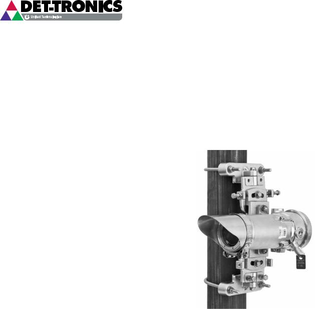
INSTRUCTIONS
Infrared Hydrocarbon Gas Detector
Open Path Eclipse
Model OPECL
Important
Be sure to read and understand the entire instruction manual before installing or operating the gas detection system. This product is intended to provide early warning of the presence of a flammable or explosive gas mixture. Proper device installation, operation, and maintenance is required to ensure safe and effective operation.
application
The Open Path Eclipse Model OPECL is an open path infrared gas detection system that provides continuous monitoring of combustible hydrocarbon gas concentrations in the range of 0 to 5 LFL-meters, over a distance of 5 to 120 meters. Standard system outputs include an electrically isolated/non-isolated 4-20 mA dc current output, with HART communication and RS-485 MODBUS communication. Alarm and fault relays are available as an option. A LON based model (with no analog or relay outputs) is available for use with Eagle Quantum Premier systems.
The system consists of two stainless steel modules
— a transmitter and a receiver, along with mounting fixture hardware. Both modules are powered from an external 24 volt DC supply. The receiver provides the measurement signal outputs, and is furnished with an onboard "status indication" LED and an internal magnetic calibration switch. The transmitter houses dual xenon flashlamps. Both modules are installed at approximately the same elevation and must be aligned to point directly at one another. No direct electrical interconnection between the two modules is required.
The Open Path Eclipse is ideal for use in harsh outdoor environments and is certified explosion-proof for use in Class I, Division 1 and Division 2 hazardous areas. It can be used as a stand-alone detector, or as part of a larger facility protection system using other Det-Tronics equipment such as the Eagle Quantum Premier Fire and Gas Detection/Releasing System.
10.1 |
©Detector Electronics Corporation 2013 |
Rev: 12/13 |
95-8556 |

OPERATION overview
theory of operation
The OPECL transmitter module illuminates a direct linear path ending at the OPECL receiver module. As flammable hydrocarbon gases intersect the light beam between the two modules, certain IR wavelengths are absorbed by the gas, while other IR wavelengths are not. The amount of IR absorption is determined by the concentration of the hydrocarbon gas. A pair of optical detectors and associated electronics located in the receiver module measure the absorption. The change in intensity of the absorbed light (active signal) is measured relative to the intensity of light at a non-absorbed wavelength (reference signal). The microprocessor computes the gas concentration and converts the value into a 4 to 20 milliampere current output signal (digital signal for EQP model), which is then communicated to external control and annunciation systems. No filter wheel motors or other moving parts are utilized in either module.
The output signal is a 4-20 mA signal (digital signal for EQP model), which corresponds to 0-5 LFL-meters. To better understand the concept of LFL-meters, refer to Figure 1, which shows how three gas clouds of different size and concentration would produce the same output of 1 LFL meter by the open path gas detection system.
note
The system must be configured for less than 60% of the full scale measuring range, with consideration to the accepted gas cloud size and concentration.
 1M @ 100% LFL
 2M @ 50% LFL
10M @ 10% LFL
A230B
OPECL OUTPUT EQUALS 1 LFL-M IN ALL THREE SCENARIOS
Figure 1—Detector Response to Three Gas Clouds of Different Size and Concentration
detectable gases
OPECL is capable of detecting most hydrocarbon gases and vapors including methane, ethane, propane, butane, and propylene. Gas type and other operational parameters are selected via digital communications. The factory calibrated setting is methane.
standard output
A 4 to 20 mA current loop corresponding to 0 to 5 LFL-meters is provided for connection to analog input devices such as gas controllers, logic controllers, or distributed control systems (DCS). To convert the mA reading to LFL-meters, use the following formula:
mA Reading –4
X 5 = LFL-Meters
16
The EQP system displays the gas concentration in LFL meters.
optional relays
The Model OPECL can be furnished with a factory installed relay output board that provides two programmable alarm relay outputs and one fault relay output. All relays are sealed and provide form C (NO/NC) contacts. The high and low alarm relays are programmable and can be set for latching or non-latching operation. When the high alarm relay is configured for non-latching operation, the detector must be connected to an auxiliary system that provides the latching function. The low alarm cannot be set above the high alarm threshold. Alarm configuration can be done with the HART or MODBUS interface. The onboard multi-color LED indicates a LOW alarm condition via a flashing red color, and a HIGH alarm condition via a steady red color. The OPECL internal magnetic switch or HART Field Communicator can be used to reset latched alarms. A short-duration magnetic switch activation of 1 second will reset latched alarms. Holding the magnetic switch closed for 2 seconds will start the calibration sequence. The external calibration line will not reset latched alarm relays.
Alarm levels for the EQP model can be set using S3 configuration software.
When the optional relay output board is installed, the OPECL receiver is certified for EEx d operation.
NOTE
Refer to“Alarm Relays” in the Specifications section of this manual for important information regarding alarm relays.
10.1 |
2 |
95-8556 |
communication
The standard OPECL system provides an analog 4-20 mA signal output, with HART and RS-485 MODBUS serial communication from the receiver module. EQP Models communicate with the EQP controller over the LON.
recording capability
Non-volatile memory is provided to save the 10 most recent calibrations, alarm/fault events, and minimum/ maximum operating temperature history. A real time clock is provided to record operating service time and to time stamp events. This information is accessible using HART and MODBUS communication, or S3 software for EQP models.
Detection Range
The standard OPECL system can cover a range of 5 to 120 meters.
Operation
Module Identification
While the OPECL transmitter and receiver modules appear physically identical, each module is labeled as “transmitter” or “receiver” on the enclosure. The physical mounting requirements for both modules are generally identical. However, there are functional and electrical characteristic differences as identified in Table 1.
Table 1—Functional and Electrical Comparison of Transmitter and Receiver
Characteristic |
Transmitter (Tx) |
Receiver (Rx) |
|
|
|
Functional Description |
Contains primary and backup xenon |
Contains opto-electronics, signal processing and |
|
flashlamps, and generates optical |
output drivers, and diagnostic electronics. |
|
energy to enable hydrocarbon |
|
|
detection. |
|
|
|
|
Power Consumption |
5.0 watts nominal @ 24 Vdc. |
6.0 watts nominal @ 24 Vdc (without relays). |
|
5.8 watts peak @ 24 Vdc. |
6.4 watts nominal @ 24 Vdc (with relays). |
|
|
|
Electrical Connections |
2 power connections only. |
From 3-7 connections depending upon specific |
|
(+24 Vdc and –24 Vdc). |
configuration (separate power and signal cables |
|
|
recommended). |
|
|
|
Onboard HART Communication |
N/A |
Connection to handheld HART communicator for |
Port |
|
system setup, commissioning, and diagnostics. |
|
|
|
Onboard LED Indicator |
Indicates normal, fault, and backup |
Indicates normal, alarm, fault, and calibration status. |
|
lamp operation status. |
Green indicates normal operation. Blinking red |
|
Green indicates normal operation. |
indicates low gas alarm condition. |
|
Yellow indicates operation in “back-up |
Steady red indicates high gas alarm condition. |
|
lamp” mode or other fault condition. |
Yellow indicates operation in “back-up lamp” mode |
|
|
or system fault. |
|
|
Calibration status is indicated by a steady red |
|
|
indication after Calibration command. |
|
|
LED operation for fault status is non-latching. LED |
|
|
operation for gas alarms is configurable for latching/ |
|
|
non-latching. |
|
|
|
Magnetic Calibration Switch |
Momentary activation overrides back- |
Momentary activation provides reset function for |
(See Figure 2 for switch location.) |
up lamp fault flash coding sequence, |
latched alarm outputs. Activation for longer than 2 |
|
permitting normal receiver operation |
seconds will initiate zero calibration. |
|
with back-up lamp. |
|
|
|
|
Factory Default Settings |
No programmable options |
Factory calibrated for methane, 0-5 LFL-meters |
|
|
full scale. See Table 2 for receiver factory default |
|
|
settings. HART communication is required to |
|
|
change the factory default settings. |
|
|
|
10.1 |
3 |
95-8556 |

PLACE CALIBRATION MAGNET
HERE TO ACTIVATE INTERNAL
REED SWITCH
B2349
Figure 2—Location of Receiver's Internal Magnetic Switch
Operating Modes
The OPECL has four operating modes: warm-up, normal, alignment and calibrate.
Warm-up
Warm-up mode is entered upon application of 24 Vdc operating power. During warm-up, the 4-20 mA current loop output will indicate warm-up, the indicating LED is yellow, and the alarm outputs are disabled. The warmup mode lasts nominally two minutes after power-up.
Normal
After warm-up mode is completed, the device automatically enters the Normal mode, and all analog and alarm outputs are enabled.
Alignment
The OPECL modules must be properly aligned before normal operation is attained. There are two alignment procedures:
1.Basic Alignment requires the OPECL Alignment Kit.
2.Fine Alignment requires the OPECL Alignment Kit and a handheld HART Communicator.
Table 2—Factory Default Settings
|
Default |
Configurable Options |
|
|
|
Gas Type |
Methane |
Ethane, Propane |
|
|
Butane, Propylene |
|
|
Special |
|
|
|
Measurement Range |
0-5 |
0-2, 0-5 |
(LFL-M) |
|
|
|
|
|
Low AlarmThreshold |
1 |
0.25 to 3 |
(LFL-M) |
|
|
|
|
|
High Alarm Threshold |
2 |
1 to 3 |
(LFL-M) |
|
|
|
|
|
Beam Block Delay |
60 Seconds |
3600 Seconds |
|
|
|
Fault Mode |
OPGD-Rx |
PIR9400, User Defined |
|
|
|
Calibrate
After alignment is completed, zero calibration is required. Span calibration of the OPECL is normally not required; however, the user has the option to verify proper calibration or to perform calibration procedures if necessary. It is recommended that the zero calibration procedure be performed annually. Refer to the "Calibration" section in this manual for details.
4-20 mA Current Loop Output
OPECL provides a linear current loop output that is proportional to the detected gas level. Fault and calibration status are also indicated by this output.
The factory default for full-scale 5 LFL-meters output is 20 mA. MODBUS interfaces also have the ability to calibrate the 4 mA and 20 mA levels.
EQP models use LON communication, and do not have a 4-20 mA output.
10.1 |
4 |
95-8556 |
Fault Indication
Faults and status conditions are indicated using the 4 20 mA analog signal output. Refer to Table 3. Signaling modes include two predefined and one user defined mode. OPGD-Rx mode (default) is available as well as a user defined mode for third party compatibility.
Table 3—Detector Status Conditions Indicated by Current Level
Status |
4-20 mA Level (±0.1) |
|
|
|
|
|
OPGD-Rx |
PIR9400 |
|
(Default) |
|
|
|
|
Normal Gas: –0.35 to 5 LFL-M |
2.88 to 20.0 |
2.88 to 20.0 |
Warmup |
1.0 |
1.0 |
Zero Calibration |
1.0 |
2.2 |
Calibration Fault |
1.0 |
1.6 |
Beam Block |
2.0 |
1.0 |
Tx Lamp Fault* |
3.0 |
2.4 |
Calibrate Active at Startup |
1.0 |
0.6 |
EE Error |
1.0 |
1.2 |
Ref. ADC Saturated |
1.0 |
0.2 |
Active ADC Saturated |
1.0 |
0.4 |
24 VDC Fault |
1.0 |
0.8 |
Zero Drift |
1.0 |
2.4 |
Flash CRC Error |
1.0 |
1.2 |
RAM Error |
1.0 |
1.2 |
Over Range |
20.4 |
20.4 |
|
|
|
*Device is still functional. Gas overrides this indication.
Transmitter LAMP Operation
Dual xenon lamps illuminate the linear detection path from the transmitter to the receiver. Should excessive degradation of the light intensity occur, the transmitter automatically increases the light output of the bulbs. The receiver recognizes this condition by the change in flash pulse coding and responds by initiating a "Tx Lamp Fault" warning signal. Total system operation is maintained, with no loss of sensitivity or detection performance.
In this mode of operation, the following occur:
1.The indicator LED turns yellow on both the transmitter and the receiver.
2.HART and MODBUS communication warn of a “Tx Lamp Fault” condition.
3.The 4-20 mA signal drops from a normal 4 mA to 3.0 mA in OPGD Rx mode (default) or 2.4 mA in PIR9400 mode. The analog output value is overridden if the gas level exceeds 0.5 LFL-meters. All gas alarm signals will occur as normal.
4.The EQP system indicates a trouble condition.
Service should be arranged as soon as possible. A new transmitter module should be installed.
note
The “Tx Lamp Fault” condition indicated by the 4 20 mA output can be acknowledged by applying a magnet to the transmitter module for at least 5 seconds. The coded flash sequence will then return to normal, which causes the 4-20 mA signal at the receiver module to also return to normal. The indicator LED on the receiver will return to green, however, the indicator LED on the transmitter will remain yellow to annunciate the lamp fault condition. This condition will continue until power to the transmitter unit is cycled or the lamps no longer operate.
10.1 |
5 |
95-8556 |
Specifications
Input Voltage (Both Modules)—
24 Vdc nominal. Operating range is 18 to 30 Vdc. Ripple cannot exceed 0.5 volts P-P.
Power Consumption (Per Module)—
Transmitter
5.0 watts nominal @ 24 Vdc, 6.9 watts @ 30 Vdc. 5.8 watts peak @ 24 Vdc, 7.5 watts peak @ 30 Vdc.
Receiver Without Relays
6.0 watts nominal @ 24 Vdc, 7.6 watts nominal @ 30 Vdc.
Receiver With Relays
6.4 watts nominal @ 24 Vdc, 8.0 watts nominal @ 30 Vdc.
TRANSMITTER LAMPS
Two xenon flashlamps, field-replaceable module.
Warmup Time—
1 minute for transmitter. 30 seconds for receiver from power-up when correctly aligned.
Current Output—
Linear 4-20 mA (isolated/non-isolated) rated at 600 ohms maximum loop resistance @ 24 Vdc operating voltage.
RELAY OUTPUTS (Optional)—
Available on Ex d approved models only.
ALARM RELAYS—
Low and High
Form C Type (NO/NC). De-Energized during Normal mode, Energized on Alarm.
Contact Rating: 5 amperes at 30 VDC.
Programmable for Latching or Non-Latching Operation.
Low Alarm: 0.25 to 3 LFL-meters
(default = 1 LFL-meters, Non-latching). High Alarm: 1 to 3 LFL-meters
(default = 2 LFL-meters, Non-latching). Alarm relays are programmable using HART or MODBUS communication.
CAUTION
When the OPECL Gas Detector is used in conjunction with an appropriate certified Control Unit and configured for a non-latching high alarm, the control unit must always latch and require a deliberate manual action to clear a high gas alarm. When used as a stand alone device, the high alarm must always be programmed for latching operation.
FAULT RELAY—
Form C Type (NO/NC). Energized during Normal mode, De-Energized on Fault or loss of power.
Contact Rating: 5 amperes at 30 VDC. Non-Latching Operation only — not programmable.
Visual Status Indicator—
Multi-color LED – Transmitter:
Green = Power on / OK
Yellow = Fault / warmup.
Multi-color LED – Receiver:
Red = Low alarm, high alarm, or calibration Green = Power on / OK
Yellow = Fault / warmup.
alarm relay setpoint range—
Low Alarm: 0.25 to 3 LFL-meters (default = 1) High Alarm: 1 to 3 LFL-meters (default = 2).
Alarm setpoint is programmable using HART or MODBUS communication.
Detection Range—
5 to 120 meters.
calibration—
OPECL systems are span calibrated for methane at the factory. Span calibration in the field is not required.
Zero calibration is accomplished in the field by one of the following methods:
–On-board magnetic reed switch
–MODBUS communication
–HART communication
–LON communication (EQP models only).
response time—
Refer to the appropriate Appendix for details.
10.1 |
6 |
95-8556 |

accuracy—
Refer to the appropriate Appendix for details.
Note
Misalignment will cause the manufacturer stated Accuracy limits to increase, but remain within the limits of EN 50241-1, -2, EN 60079-29-4, and IEC 60079-29-4.
Temperature Range—
Operating: –55°C to +60°C (–67°F to +140°F)
Storage: |
–55°C to +85°C (–67°F to +185°F) |
Hazardous Locations: Refer to the appropriate Appendix for correct ambient temperature range:
Appendix A - FM
Appendix B - CSA
Appendix C - ATEX
Appendix D - IEC
HUMIDITY—
5 to 99% relative humidity; designed for outdoor applications.
operating pressure—
91.5 - 105.5 kPA non-compensated.
Measurement Range—
0-5 LFL-meters.
Interference resistance—
Immune to sun and flare radiation, tested to 800 ±50 W/m2 ≥ 3° to optical axis and common contaminants.
SELF-DIAGNOSTIC TEST—
Fail-Safe operation ensured by performing all critical tests once per second.
Module Housing Material—
316 stainless steel (CF8M).
Conduit Entry Options—
Two entries, 3/4 inch NPT or 25 mm.
HART COMMUNICATION PORT—
An intrinsically safe port is provided on the receiver for connecting a Rosemount/Emerson HART Communicator.
•Maximum separation distance between receiver and communicator is 610 meters.
Optics Protection—
Stainless steel brow provides a degree of protection against windblown dirt and rain. Heated optics mitigate against ice and dew formation.
Wiring—
Field wiring screw terminals are UL/CSA rated for up to 14 AWG shielded wire, and are DIN/VDE rated for 2.5 mm2 wire. Screw terminal required torque range is 3.5– 4.4 lb.-in. (0.4-0.5 N·m). Receiver can be wired using 3 or 4 wires. Transmitter requires two wires (power only).
Certification—
FM |
® |
APPROVED |
|
For complete approval details, refer to the appropriate Appendix:
Appendix A - FM
Appendix B - CSA
Appendix C - ATEX
Appendix D - IECEx
Appendix E - Other Approvals
10.1 |
7 |
95-8556 |

Dimensions—
Module
Length: 11.5 inches (29 cm) Diameter: 3.5 inches (9 cm) nominal
4.5 inches (11 cm) maximum
Mounting Plate
Height: |
14.5 inches (37 cm) |
Width: |
6.5 inches (16 cm) |
Designed to attach to a 4 inch nominal diameter pipe.
Refer to Figure 3A for mounted dimensions and Figure 3B for maximum pan/tilt angles of the mounting plate.
14.5
(36.8)
14.3
(36.3)
7.8
(19.8)
Shipping Weight—
Transmitter or receiver (replacement): 30 pounds (14 kg)
Transmitter and receiver with mounting hardware: 75 pounds (34 kg)
warranty—
2 year limited warranty from date of manufacture.
± 8.0° |
19.0°
7.3
(18.5)
7.8
2251E |
(19.8) |
A2634 |
|
||
Figure 3A—Mounted Dimensions of OPECL in Inches (cm) |
Figure 3B—Maximum Pan/Tilt Angles of Mounting Plate |
|
10.1 |
8 |
95-8556 |
Important Safety Notes
CAUTION
The wiring procedures in this manual are intended to ensure proper functioning of the system under normal conditions. However, because of the many variations in wiring codes and regulations, total compliance to these ordinances cannot be guaranteed. Be certain that all wiring complies with the NEC as well as all local ordinances. If in doubt, consult the authority having jurisdiction before wiring the system. Installation must be done by a properly trained person.
CAUTION
This product has been tested and approved for use in hazardous areas. However, it must be properly installed and used only under the conditions specified within this manual and the specific approval certificates. Any device modification, improper installation, or use in a faulty or incomplete configuration will render warranty and product certifications invalid.
CAUTION
The system contains no user serviceable internal components. Service or repair should never be attempted by the user. Device repair should be performed only by the manufacturer or trained service personnel.
Liabilities
The manufacturer’s warranty for this product is void, and all liability for proper function of the system is irrevocably transferred to the owner or operator in the event that the device is serviced or repaired by personnel not employed or authorized by Detector Electronics Corporation, or if the system is used in a manner not conforming to its intended use.
Caution
Observe precautions for handling electrostatic sensitive devices.
note
The Open Path Eclipse is intended for detection of hydrocarbon vapors only. The device will not detect hydrogen gas.
note
The terminal compartment for OPECL without relays is designed for either an increased safety “e” termination or a flameproof “d” termination of the supply cable. If a flameproof connection is chosen, then an ATEX certified cable entry device must be used. The OPECL with relays requires Ex d cable entry devices only.
Installation
Identification of vapor(s) to be detected
It is necessary to identify the flammable vapor(s) of interest at the job site in order to determine the proper calibration gas setting for OPECL. In addition, the physical and fire hazard properties of the vapor, such as vapor density and flashpoint should be identified and used to assist in selecting the optimum detector mounting locations within the area. The detector must be installed by qualified personnel only, following local electrical equipment installation practices.
System Location considerations
The OPECL system is designed for installation in hazardous industrial areas. Each module is normally installed using a solid vertical steel post or flat surface mounting adapter to support the weight of the module. The modules must be strategically located so that the hydrocarbon vapor(s) to be detected will intersect the light beam generated by the transmitter module. Dispersion characteristics and behavior of the vapor cloud resulting from a gas leak can be difficult to estimate due to the significant number of variables that exist at different applications. Identification of expected gas leakage source(s), leak scenario identification, and onsite leak simulation are the steps generally recommended to provide the most accurate means of identifying optimum system installation locations.
In all cases, the beam path and surrounding area should be kept free of obstructions that could block the infrared beam or hinder the free movement of air within the area. A clear beam path of 20 CM diameter or greater is required. The system is immune to the effects of exposure to both direct and reflected sunlight.
Avoid installation in areas with obstructions such as steam vents and plumes, smoke stacks and chimneys, walkways and personnel areas, splash and sprayed water, parking, loading, cranes, vehicle-related areas such as bus stops, road junctions, and vegetation such as trees, shrubs, grass etc.
Det-Tronics Field Service Engineering group routinely provides jobsite application surveys and analysis for customers, and their services are highly recommended if guidance on optimum installation locations is required. Additional guidance on the positioning of gas detectors for optimum coverage is contained in BS6959 and other national codes. Consult these codes of practice when determining where detectors are to be located.
10.1 |
9 |
95-8556 |
Consideration of the following system location guidelines is also recommended:
LED Visibility
Select a mounting orientation where the Open Path Eclipse status indication LED is visible to personnel within the area.
Module Separation Distance
The transmitter and receiver modules must be installed directly facing each other across the area to be protected. Physical obstructions in the direct line of sight between the modules are not permitted. The overall line of sight distance between the modules must not fall outside the specified operating distance range (refer to “Specifications” for details).
Multiple System Installations
If multiple OPECL systems are to be installed, ensure that each receiver can view only the intended transmitter.
System Mounting Elevation
In all cases, the modules should be installed at the same elevation above grade to ensure that alignment capability and foul weather performance are not compromised. For detection of lighter than air vapors such as methane, installation of modules at approximately 2 meters above grade minimizes typical beam block conditions due to human activities, while enabling satisfactory detection capability. For detection of heavier than air vapors, installation of detectors below the expected leakage source is generally recommended unless nuisance beam blocks will occur at an unacceptable rate. In this case, identification and analysis of application specific conditions should be completed to determine the optimum installation elevation.
Sources of Heavy Contamination
Avoid locations where high levels of contaminants will persistently be blown onto the detector windows. Potential sources of heavy contamination include generator / turbine exhausts, flarestacks, drilling equipment, process vents / chimneys, etc. If sources of heavy contamination cannot be avoided, consider fitting extra shielding and/or providing good access for routine cleaning.
Snow and Ice in Ambients Below –20°C
The heated optics on both modules will melt snow or ice on the windows in ambient temperatures down to approximately –20°C. Below this temperature, snow or ice blown onto the window will not be melted until the ambient temperature rises. If longterm outdoor operation in very cold climates is intended, extra shielding / covers are recommended to prevent accumulation of snow and ice on the windows.
Deluge and Flooding
The modules are rated IP66/IP67 and will not be damaged by occasional deluge or flooding. However, during such an event, the unit will completely lose it’s IR signal and will enter the “Beam-Block / Fault” state. In addition, when the deluge / flooding subsides, there is the possibility that contaminants will be left on the windows. Install the modules away from areas prone to deluge or flooding.
Areas Prone to Subsidence and Settling
Avoid installation of the modules in areas where problems with subsidence, settling or thawing of permafrost can occur or cause significant movement. If such locations cannot be avoided, the foundations of the mounting structure should be engineered to minimize any angular movements between the receiver and transmitter.
Areas Prone to Earthquakes
In the event of an earthquake, there is a chance that the modules will become misaligned with respect to each other. As long as the modules do not suffer from direct mechanical impact damage during an earthquake, they should remain undamaged by such events. After an earthquake, it is recommended that the system alignment be checked. Anti-vibration mounts are unlikely to be of any benefit and are not recommended.
Misalignment by Accidental Impact
Locations where there is a significant likelihood of equipment, personnel or moving objects accidentally knocking the modules out of alignment should be avoided where possible. If such locations cannot be avoided, measures including improved mechanical protection and warning notices should be considered.
10.1 |
10 |
95-8556 |
Module Mounting Recommendations
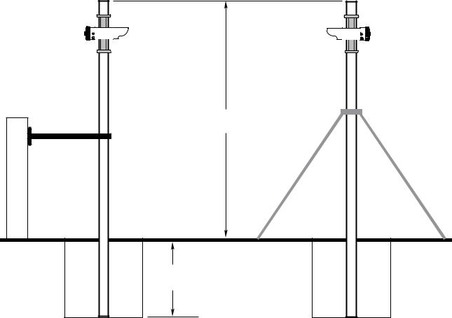
OPECL modules must be affixed to a solid, non-vibrating structure capable of supporting a minimum of 100 lbs (46 kg), located within the system’s rated separation distance.
A building wall, a heavy steel I-beam, or nearly any type of masonry typically provides the most rigid mounting surface available. However, avoid the use of wood structures or supports if the possibility of warping exists.
When using a vertical post, the post must be absolutely stable and without vibration. Square stock pole is recommended. Mounting height should not exceed 3 meters.
The post can be set into the ground or attached to a secure surface. If a post is set into the ground, the portion below grade should be set in concrete at least 1 meter deep.
IMPORTANT
In all cases, consider whether additional bracing or support is needed to ensure the structural integrity of the module installation. See Figure 4. Remember that accurate module alignment is essential for proper performance of an open path gas detection system, and even a small amount of movement can have a detrimental effect on alignment. This is especially true for installations with significant module separation distances.
3 METERS
MAXIMUM HEIGHT
 IMMOVABLE
STRUCTURE
1 METER
OR BELOW FROST LINE
A2501
NOTE: INSTALLATIONS NEAR MAXIMUM HEIGHT TYPICALLY REQUIRE
BRACING TO ENSURE NO MOVEMENT OF THE OPECL DETECTOR.
Figure 4—Example of Bracing Added to Vertical Mounting Poles for Increased Robustness of OPECL Installation
10.1 |
11 |
95-8556 |
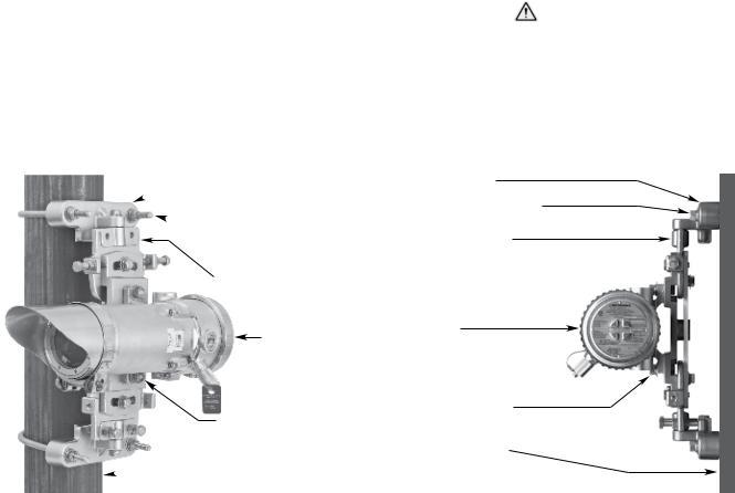
Module mounting options include:
•A vertical post with a nominal outside diameter of 4.5”
(11.43 cm). Acceptable outside diameter range is 4.0 to 5.0 inches. See Figure 5.
•For flat surface mounting, refer to Figure 6.
Mounting Sequence
1.Attach the OPECL module to the pan-tilt mounting plate and tighten the OPECL mounting bolts to 20 lb.-ft. minimum.
2.Install the lower mounting bracket.
3.Place the pan-tilt mounting plate on the lower bracket and install the upper mounting bracket. Tighten the mounting hardware to 20 lb.-ft. minimum. Tighten the alignment bolts/nuts hand tight only.
note
Anti-seize material (provided) must be applied to the U-bolt threads at the time of installation to prevent galling.
24 VDC power SUPPLY requirements
Calculate the total gas detection system power consumption rate in watts from cold start-up. Select a power supply with adequate capability for the calculated load. Ensure that the selected power supply provides regulated and filtered 24 Vdc power for the entire system. If a back-up power system is required,
 MOUNTING BRACKET (2)
 U-BOLT* (2)
PAN-TILT MOUNTING PLATE
OPECL MODULE
OPECL MOUNTING BOLT (2)
 MOUNTING POST
B2305
*APPLY ANTI-SEIZE MATERIAL TO U-BOLT THREADS TO PREVENT GALLING.
Figure 5—OPECL Gas Detector Mounted to Vertical Post
a float-type battery charging system is recommended. If an existing source of 24 Vdc power is being utilized, verify that system requirements are met.
note
If disconnection of power is required, separate disconnect capability must be provided.
Wiring cable requirements
Always use proper cabling type and diameter for input power as well as output signal wiring. 14 to 18 AWG shielded stranded copper wire is recommended. For EQP models, refer to the EQP system manual (95-8533) for specific wiring requirements and recommendations.
Always install a properly sized master power fuse or breaker on the system power circuit.
note
The use of shielded cable in conduit or shielded armored cable is required for ATEX conformance. In applications where the wiring is installed in conduit,dedicated conduit is recommended. Avoid low frequency, high voltage, and non-signaling conductors to prevent nuisance EMI problems.
caution
The use of proper conduit installation techniques, breathers, glands, and seals is required to prevent water ingress and/or maintain the explosion-proof rating.
MOUNTING BRACKET (2)
MOUNTING BOLT (2 PER BRACKET)
PAN-TILT MOUNTING PLATE
OPECL MODULE
OPECL MOUNTING BOLT (2)
FLAT MOUNTING SURFACE
A2306
Figure 6—OPECL Gas Detector Mounted to Flat Surface
10.1 |
12 |
95-8556 |

Power Wiring Size and Maximum Length
1.To ensure proper operation, OPECL power terminals (terminals 1 and 2 for Rx and Tx) and 4-20 mA terminals (terminals 6 and 7 for Rx) must receive 18 Vdc minimum. 24 Vdc is recommended. Terminals 1 and 4, and terminals 2 and 5 on the OPECL Rx are internally connected (see wiring diagrams).
2.Always determine voltage drops that will occur to ensure that 24 Vdc is delivered to the OPECL.
3.Normally, nothing smaller than 18 AWG (1.0 mm2) is recommended by Det-Tronics for OPECL power cabling.
Wire size requirements are dependent upon power supply voltage and wire length.
The maximum distance between the OPECL detector and its power supply is determined by the maximum allowable voltage drop for the power wiring loop. If the voltage drop is exceeded, the device will not operate. To determine the maximum power loop voltage drop, subtract the minimum operating voltage for the device (18 Vdc) from the minimum output voltage of the power supply.
To determine the actual maximum wire length:
1.Divide the maximum allowable voltage drop by the maximum current draw of the OPECL (0.35 A),
2.Divide by the resistance of the wire (ohms/foot value available in wire manufacturer’s specification data sheet),
3.Divide by 2.
For example: Consider an installation using 18 AWG wiring with a power supply providing 24 Vdc.
Power supply voltage = 24 Vdc,
OPECL minimum operating voltage = 18 Vdc
24 – 18 = 6 Vdc
Maximum Voltage Drop = 6
Maximum Current = 0.35 A
Wire Resistance in Ohms/Foot = 0.006523
6 ÷ 0.35 ÷ 0.006523 ÷ 2 = 1314 feet
optional relays
Optional relay contacts are “dry”, meaning that the installer must provide the voltage to the common terminal of the relay output.
AC voltage should not be switched directly using the OPECL relays. The use of an external relay is required if AC voltage must be switched by the OPECL relays.
In order to change alarm relay settings from the factory default settings, it is recommended to utilize a HART Field Communicator. Contact the factory for further assistance.
NOTE
Refer to“Alarm Relays” in the Specifications section of this manual for important information regarding alarm relays.
The relay board must temporarily be removed from the OPECL termination compartment to connect the relay output field wiring cables. After the relay wiring is connected, re-install the relay board using the three captive screws. Refer to Figure 7.
Note: Relays are not available on EQP models.
FACTORY INSTALLED WIRING TO RELAY BOARD (DO NOT REMOVE)
 CAPTIVE SCREWS (3)
A2133 |
RELAY TERMINAL BLOCK |
Figure 7—OPECL Wiring Termination Compartment with Optional Relay Board Removed
10.1 |
13 |
95-8556 |
 Loading...