


|
|
|
|
|
|
|
|
|
|
|
|
|
|
|
|
|
|
|
|
|
|
|
|
|
|
|
Safety Manual |
95-8599 |
|
Eagle Quantum Premier®
SIL 2 Rated Fire & Gas System
|
|
|
|
|
|
|
|
|
|
|
|
|
|
|
|
|
|
|
|
|
|
|
|
|
|
|
|
|
|
|
|
|
|
|
|
|
|
|
|
|
|
|
|
|
|
|
|
|
|
|
|
|
|
|
|
|
|
|
|
|
|
|
|
|
|
|
|
|
|
|
|
|
|
|
|
|
|
|
|
|
|
|
|
|
|
|
|
|
|
|
|
|
|
|
|
|
|
|
|
|
|
|
|
|
|
|
|
|
|
|
|
|
|
|
|
|
|
|
|
|
|
|
|
|
|
|
|
|
|
|
|
|
|
|
|
|
|
|
|
|
|
|
|
|
|
|
|
|
|
|
|
|
|
|
|
|
|
|
|
|
|
|
|
|
|
|
|
|
|
|
|
|
|
|
|
|
|
|
|
|
|
|
|
|
|
|
|
|
|
|
|
|
|
|
|
|
|
|
|
|
|
|
|
|
|
|
|
|
|
|
|
|
|
|
|
|
|
|
|
|
|
|
|
|
|
|
|
|
|
|
|
|
|
|
|
|
|
|
|
|
|
|
|
|
|
|
|
|
|
|
|
|
|
|
|
|
|
|
|
|
|
|
|
|
|
|
|
|
|
|
|
|
|
|
|
|
|
|
|
|
|
|
|
|
|
|
|
|
|
|
|
|
|
|
|
|
|
|
|
|
|
|
|
|
|
|
|
|
|
|
|
|
|
|
|
|
|
|
|
|
|
|
|
|
|
|
|
|
|
|
|
|
|
|
|
|
|
|
|
|
|
|
|
|
|
|
|
|
|
|
|
|
|
|
|
|
|
|
|
|
|
|
|
|
|
|
|
|
|
|
|
|
|
|
|
|
|
|
|
|
|
|
|
|
|
|
|
|
|
|
|
|
|
|
|
|
|
|
|
|
|
|
|
|
|
|
|
|
|
|
|
|
|
|
|
|
|
|
|
|
|
|
|
|
|
|
|
|
|
|
|
|
|
|
|
|
|
|
|
|
|
|
|
|
|
|
|
|
|
|
|
|
|
|
|
|
|
|
|
|
5.1 |
|
|
|
|
|
|
|
Rev: 3/13 |
95-8599 |
|||||||||||||||
|
|
|
|
|
|
|
||||||||||||||||||||
Table Of Contents |
|
INTRODUCTION. . . . . . . . . . . . . . . . . . . . . . . . . . . . . . . . . . . . . . . . . . . |
1 |
Quality Policy Statement. . . . . . . . . . . . . . . . . . . . . . . . . . . . . . . . . . |
1 |
Scope. . . . . . . . . . . . . . . . . . . . . . . . . . . . . . . . . . . . . . . . . . . . . . . . |
. 1 |
Document Structure. . . . . . . . . . . . . . . . . . . . . . . . . . . . . . . . . . . . . |
. 2 |
PRODUCT OVERVIEW. . . . . . . . . . . . . . . . . . . . . . . . . . . . . . . . . . . . . . |
2 |
EQP System. . . . . . . . . . . . . . . . . . . . . . . . . . . . . . . . . . . . . . . . . . . |
. 2 |
EQP Safety System . . . . . . . . . . . . . . . . . . . . . . . . . . . . . . . . . . . . . |
. 2 |
EQP Safety Controllers. . . . . . . . . . . . . . . . . . . . . . . . . . . . . . . . . . . |
5 |
EQP Safety Devices.. . . . . . . . . . . . . . . . . . . . . . . . . . . . . . . . . . . . . |
6 |
EQPSL . . . . . . . . . . . . . . . . . . . . . . . . . . . . . . . . . . . . . . . . . . . . . . . |
. 6 |
X3301-SIL.. . . . . . . . . . . . . . . . . . . . . . . . . . . . . . . . . . . . . . . . . . . . . |
7 |
Model PIRECL-SIL . . . . . . . . . . . . . . . . . . . . . . . . . . . . . . . . . . . . . . |
. 7 |
AIM-SIL Analog Input Module. . . . . . . . . . . . . . . . . . . . . . . . . . . . . . |
7 |
EDIO-SIL Enhanced Digital Input/Output Module . . . . . . . . . . . . . . |
. 7 |
Power Supplies. . . . . . . . . . . . . . . . . . . . . . . . . . . . . . . . . . . . . . . . . |
8 |
S3 Configuration Software. . . . . . . . . . . . . . . . . . . . . . . . . . . . . . . . . |
8 |
PROOF TESTING.. . . . . . . . . . . . . . . . . . . . . . . . . . . . . . . . . . . . . . . . . |
10 |
EDIO Input Channel Proof Test.. .. .. .. .. .. .. .. .. .. .. .. .. .. .. .. .. .. .. .. .. .. .. .. .. .. .. .. 10 |
|
EDIO Output Channel Proof Test. . . . . . . . . . . . . . . . . . . . . . . . . . . |
10 |
AIM Input Channel Proof Test. . . . . . . . . . . . . . . . . . . . . . . . . . . . . |
10 |
X3301 Visual Field Inspection Proof Test. . . . . . . . . . . . . . . . . . . . |
10 |
X3301 Magnetic Oi Proof Test . . . . . . . . . . . . . . . . . . . . . . . . . . . . . |
11 |
PIRECL Visual Field Inspection Proof Test. . . . . . . . . . . . . . . . . . . |
11 |
PIRECL Gas Response Proof Test. . . . . . . . . . . . . . . . . . . . . . . . . |
11 |
EQP User Logic Verification.. . . . . . . . . . . . . . . . . . . . . . . . . . . . . . |
11 |
INSTALLATION.. . . . . . . . . . . . . . . . . . . . . . . . . . . . . . . . . . . . . . . . . . . |
11 |
Commissioning Personnel . . . . . . . . . . . . . . . . . . . . . . . . . . . . . . . . |
11 |
SUITABLE APPLICATIONS. . . . . . . . . . . . . . . . . . . . . . . . . . . . . . . . . . |
11 |
General Application Requirements. . . . . . . . . . . . . . . . . . . . . . . . . |
12 |
APPENDIX A – SUMMARY OF SAFETY RELATED DATA . . . . . . . . . . 16
Appendix B – EQP Controller logic gate table.. . . . . . . . . 19

safety manual
Eagle Quantum Premier®
SIL 2 Rated Fire & Gas System
Note
Where a definition of the term or abbreviation is given in IEC 61508-4 “Definitions and Abbreviations”, the definition from the standard is given first in quotation marks, followed by further explanation if this is necessary.
INTRODUCTION
This Safety Manual describes the actions that must be taken to use the Det-Tronics Eagle Quantum Premier® (EQP) Safety System in safety-related applications.
The actions that are described can be either technical or procedural. For example, a procedural action would be the need to maintain password protection of configuration programs, so that non-approved staff cannot modify these.
This document is limited to those actions that are required to ensure compliance with the relevant safety certifications and standards. Other documents such as Manuals and Data Sheets must be referred to for information outside the scope of this document. These documents can be found on the Det-Tronics website www.det-tronics.com.
The Safety Manual is approved and certified by exida® as part of the overall EQP Safety System. Satisfying the requirements it describes is a necessary part of using the EQP Safety System in safety-related applications.
Failure to complete the actions described in this document would contravene the certification requirements.
Completing the actions described in this document will only satisfy some of the requirements defined by IEC 61508 for safety-related applications.
It will be necessary to satisfy the full requirements of IEC 61508, and for Process Industry applications, the requirements of IEC 61511, in order to use the Det-Tronics EQP Safety System in safety-related applications.
Further, it is the responsibility of the user to ensure that the EQP Safety System is suitable for the chosen application and complies with the appropriate application standards.
QUALITY POLICY STATEMENT
All quality assurance control measures necessary for safety management as specified in IEC 61508 Part 1 have been implemented. The quality management system of Det-Tronics is based on the requirements of EN ISO 9001 and ANSI/ASQC Q9001 through the application of the United Technologies Company Achieving Competitive Excellence (ACE) program. In addition, the Quality Management System complies with the European ATEX Directive requirements per EN 13980, the International Electrotechnical Commission requirements per OD005/V2, and the supervised testing requirements per ISO 17025.
SCOPE
The Det-Tronics EQP Safety System is intended for use as part of a programmable electronic system as defined by IEC 61508. It is suitable for low demand safety functions up to safety integrity level 2 (SIL 2).
The safety critical functions for the EQP Safety System include the following:
–Fire input from X3301 and/or EDIO and/or AIM
–Gas alarm from PIRECL and/or EDIO and/or AIM
–Annunciation/Release from EDIO
–System logic for processing and mapping inputs and outputs.
5.1 |
©Detector Electronics Corporation 2013 |
Rev: 3/13 |
95-8599 |
The safety related functions of the EQP Safety System include the following:
–Trouble annunciation for compromised safety function by de-energizing the Controller’s Trouble relay
–Digital input for lockout of inhibits.
The EQP Safety System employs a 1oo1D (i.e. 1 out of 1 with diagnostics) architecture to achieve SIL 2. EQP Safety Controllers may be used in redundant mode to increase system availability, but this is not required for the safety-related performance of the system.
Configuring and programming the EQP Safety System must be via a software program known as Safety System Software (S3).
In addition to completing the actions specifically related to the EQP Safety System, it is necessary to satisfy the wider requirements of IEC 61508. This includes such elements within the framework of the safety lifecycle, such as hazard and risk analysis and defining the safety instrumented function. This work must be carried out through appropriate and competent Safety Management procedures and staff.
DOCUMENT STRUCTURE
This Safety Manual describes the actions that must be taken to use the Det-Tronics EQP Safety System in safety-related applications. The main sections are as follows:
Introduction
Product Overview gives an overview of the Det-Tronics product range in general and the EQP Safety products in particular.
Proof Testing describes the proof testing that is necessary.
Suitable Applications describes the use of the Det Tronics EQP Safety System in practical applications. Included are failure rate data and PFDavg calculations.
Appendix A provides a summary of the essential data for safety applications for the Det-Tronics EQP Safety System.
Appendix B gives logic instructions and their restrictions for low demand SIL 2 applications.
PRODUCT OVERVIEW
EQP SYSTEM
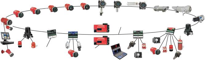
The EQP System (on which the Det-Tronics EQP Safety System is based) was originally developed to meet the requirements of industrial fire and gas detection and mitigation. The system comprises (see Figure 1):
•Input / output modules
•Field devices for fire and gas detection
•Controllers which can be programmed to carry out the control of the fire and gas system
•Power supplies and other miscellaneous hardware
•S3 software which is used to configure the system and to generate the logic programs which will be run by the Controllers
•A proprietary protocol known as Eagle Quantum
Premier Safety Loop (EQPSL), which provides communication between field devices and the Controllers.
NOTE
For additional information regarding set-up and installation of the EQP system, refer to the EQP system manual, form number 95-8533.
EQP SAFETY SYSTEM
The Det-Tronics EQP Safety System uses the following specifically developed components (see Figure 2):
•EQ3XXX – EQP Controller
•EQ3730EDIO – Enhanced Discrete Input/Output
(EDIO) Module
•EQ3710AIM – Analog Input Module
•X3301 – Multispectrum IR Flame Detector
•PIRECL – Infrared Gas Detector
The data required to establish the suitability of the EQP Safety System for safety-related applications is given in Appendix A of this Safety Manual.
EQP Safety System components and standard components can be used together. The non-safety certified components are classed as non-interfering. A list of all the devices available for the EQP system is maintained at www.det-tronics.com and is shown below.
5.1 |
2 |
95-8599 |
|
|
|
|
4. UV/IR Hydrocarbon Flame Detector |
5. |
UV Flame Detector |
8. Hydrocarbon Combustible |
||||||||||
22. Flame Detector with |
|
|
|
|
|
|
|
7. H2S Gas Sensor with Display |
Gas Detector with Display |
||||||||
|
|
3. Single Frequency IR |
|
|
|
|
|
9. Combustible Gas Open Path Detector |
|||||||||
Explosion-Proof |
|
|
Hydrocarbon Flame Detector |
|
|
|
|
|
|
|
|
|
|
||||
Camera |
2. Multispectrum IR |
|
|
|
|
|
|
|
|
|
|
|
|
|
|||
|
|
|
|
6. Toxic Gas Detector with Display |
|
|
|
|
|||||||||
|
Hydrogen Flame Detector |
|
|
|
|
10. Hydrocarbon Combustible |
|||||||||||
1. |
Multispectrum IR |
|
|
|
|
|
|
|
|
|
|
|
|
|
|||
|
Hydrocarbon Flame Detector |
|
|
|
|
|
|
|
|
|
|
|
|
|
Gas Detector |
||
|
19. Signal Audible Module |
|
|
|
|
|
|
|
|
|
14. Local Operating Network/ |
|
12. Discrete Inputs and Outputs Module |
||||
|
|
|
|
|
|
|
|
|
|
Signaling Line Circuit |
|
||||||
|
|
|
18. Relay Output Module |
|
|
|
|
|
|
|
|
|
13. Single-Fire-Hazard Supression Module |
||||
|
|
|
|
17. Analog (4-20 mA) Input Module |
|
|
|
|
|
|
|
|
|
|
|
|
|
21. Surveillance Digital Video |
|
|
|
|
|
|
|
|
|
|
|
|
|
|
|
||
Recorder and Remote Station |
|
|
|
|
16. Redundant Safety System Controllers |
|
|
|
|
|
|
|
|||||
|
|
|
|
|
|
|
|
|
|
|
|
|
|
||||
|
|
|
|
|
|
|
|
|
|
|
|
|
|
|
|
|
11. Combustible Gas Detector |
|
|
|
|
|
|
|
|
|
|
|
|
|
|
|
|
|
|
|
|
|
|
|
|
|
|
|
|
|
|
|
|
|
|
|
|
|
|
|
|
|
|
|
|
|
|
|
|
|
|
|
|
||
|
|
Links to 3rd-Party Control |
|
|
|
|
|
|
|
|
|
|
|
|
|
|
|
|
|
|
|
Interface to ControlNet and Modbus |
|
|
|
|
|
|
|
|
|
|
|||
|
|
|
System or PLC |
|
|
|
|
|
|
|
|
|
|
||||
20. Explosion-Proof |
|
|
|
|
|
|
|
|
|
|
|
|
|
|
|
||
Camera |
|
|
|
|
|
15. Operator Station |
|
|
|
|
|||||||
|
|
|
|
|
|
|
|
and Software |
|
|
|
|
|||||
|
|
|
|
|
|
|
|
|
|
|
|
|
|
|
|
|
|
Figure 1—Components of a Det-Tronics EQP System
Non-Interfering Modules
•EQ2400NE – Network Extender
•EQ2400PLR – Physical Layer Repeater
•EQ3LTM LON Termination Module (Redundant
Controllers Only)
•008981-001 Controller to Controller High Speed Serial
Cable (Redundant Controllers Only)
•EQPSL Network Cables – Refer to cable specification information in the EQP system manual (form 95-8533).
•EQ3700DCIO – Discrete Input/Output Module
•EQ3720RM – Relay Module
•EQ3750 – Addressable Smoke and Heat Module
•X2200UV – Ultraviolet Flame Detector
•X5200UVIR – Ultraviolet/Infrared Flame Detector
•X9800IR – Infrared Flame Detector
•EQ2200UV – Ultraviolet Flame Detector
•EQ2200UVHT – High Temperature Ultraviolet Flame
Detector
•EQ2200UVIR – Ultraviolet/Infrared Flame Detector
•EQ2200DCU – Digital Communication Unit
•EQ2200DCUEX – Discrete Control Unit with Catalytic
Gas Sensor
•EQ2200IDC – Initiating Device Circuit
•EQ2200IDCSC – Initiating Device Circuit Short Circuit
•EQ2500ARM – Agent Release Module
•EQ2500SAM – Signal Audible Module
•EQ2100PSM – Power Supply Monitor
•EQ2220GFM – Ground Fault Monitor
•008056-001 – HART Interface Module
•OPECL – Open Path Eclipse Gas Detector
•FlexVu UD10 Universal Display Module
Configuration Software
• Det-Tronics Safety System Software (S3)
5.1 |
3 |
95-8599 |
EQP Safety System Component Overview
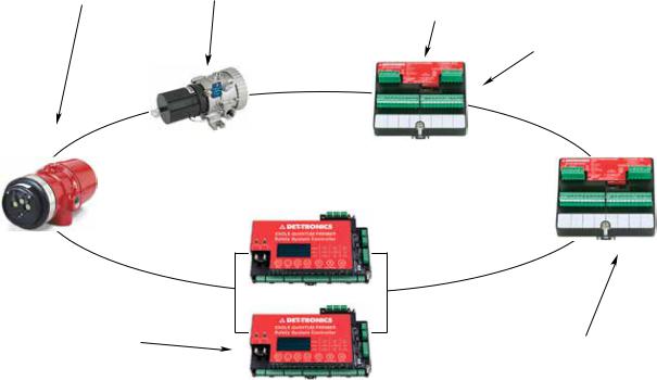
Figure 2 gives an overview of the role that each element of the EQP Safety System has in implementing the safety function.
Safety Certified Product Identification
All safety certified EQP System modules are clearly identified as such on the product label.
X3301 MULTISPECTRUM IR FLAME DETECTOR IS A SINGLE INPUT DEVICE SUITABLE IN LOW DEMAND SIL 2 SAFETY INSTRUMENTED SYSTEMS.
MODEL PIRECL IR COMBUSTIBLE GAS DETECTOR IS A SINGLE INPUT DEVICE SUITABLE IN LOW DEMAND SIL 2 SAFETY INSTRUMENTED SYSTEMS.
EDIO SAFETY MODULE CONFIGURED FOR DIGITAL INPUTS. MONITORS THE INPUTS AND ALSO CHECKS FOR LINE FAULTS. INTERNAL DIAGNOSTICS CHECK THAT THE MODULE IS OPERATING CORRECTLY.
EDIO SAFETY MODULE CONFIGURED FOR DIGITAL OUTPUTS. OBEYS COMMANDS TO SET THE OUTPUTS SENT BY THE CONTROLLER. INTERNAL DIAGNOSTICS CHECK THAT THE MODULE IS OPERATING CORRECTLY. IF A FAULT IS DETECTED, OUTPUTS WILL BE SET TO THEIR SAFE STATE OF HOLD LAST STATE.
EQP SAFETY CONTROLLER – RUNS THE SAFETY APPLICATION PROGRAM AND CARRIES OUT DIAGNOSTIC CHECKS TO ENSURE IT IS OPERATING CORRECTLY. IF A FAULT IS DETECTED, IT WILL BE INDICATED BY DE-ENERGIZING THE TROUBLE RELAY.
D2343
Figure 2—Det-Tronics EQP Safety System Component Overview
AIM SAFETY MODULE MONITORS 4-20 mA ANALOG INPUTS. INTERNAL DIAGNOSTICS CHECK THAT THE MODULE IS OPERATING CORRECTLY.
5.1 |
4 |
95-8599 |
EQP SAFETY CONTROLLERS
The EQP Safety Controllers share a common hardware and software platform with standard EQP Controllers. The SIL rated version of the Controller conducts additional diagnostic checks and annunciates additional fault conditions.
Safety compliance is assured by additional diagnostics, which detect failures and take appropriate action should errors be detected.
If the EQP Safety Controller detects a “dangerous” fault in itself (i.e. one that would prevent the EQP Safety System from carrying out its safety function) it will de energize the trouble relay. The fault causing the Controller’s trouble relay to de-energize must be investigated and corrected within the time period determined by SIF verification calculations for the particular application.
Run Mode
Run Mode is the state in which the Det-Tronics EQP Safety System is acting as a safety-related system and carrying out its safety function. When the system is in this state, it is not possible to make modifications to configuration parameters or control logic.
Program Mode
The system enters Program Mode when configuration parameters are downloaded to the system. The Controller trouble relay is de-energized while in this mode as an indication. When the EQP System is in Program Mode, the user is responsible for maintaining a safe state.
NOTE
When there is a change of configuration, the user is required to perform a validation test of the change.
Safe and Non-interfering Data
An EQP application program can read data from safety related and non-interfering sources. Data from non interfering sources must not be used in logic to block or disable safety-related signals in the safety loop. For example, data coming into the system from a non interfering field device should not be used to block or disable an alarm output, but It could be used to activate a common alarm used by safety-related logic.
Communication with Remote Modbus Devices
EQP Safety Controllers can read or write data to Remote Modbus devices. Any data read from such devices is not safety-related and shall not be used to block or disable safety-related logic.
EQP Controller Inhibit Lockout
Device inhibits allow input and output signals to be blocked to allow the user to perform maintenance and testing without affecting system outputs. Example: If a flame detector is inhibited, a flame can be presented to the detector and the fire alarm will not be registered by the controller. Subsequently, no action will be performed by the controller. Therefore inhibits are classified as a safety related issue. If a device is inhibited, it will no longer perform its safety function. For this reason, there is a global inhibit lockout feature.
Input channel four of the safety controller is designated as the inhibit lockout channel. The channel must be configured as “Inhibit Enabled” via the EQP controller configuration screen in the S3 software. A normally open switch must be wired to channel four to perform the inhibit enable function. When the switch is open, inhibits are not allowed. When the switch is closed, inhibits can be activated from the controller via user configured logic or from the individual device point displays on the S3 software.
When the inhibit lockout switch changes state, it is logged in the EQP controller. Additionally, individual devices are logged when they are put into the inhibit state.
It is the user’s responsibility to create and enforce an appropriate lockout policy for the site.
5.1 |
5 |
95-8599 |
EQP Safety Controller Diagnostic Checks
The EQP Safety Controller automatically carries out a number of diagnostic checks on a continuous basis. A number of other diagnostic tests are also conducted to ensure the integrity of the EQPSL communication network and proper operation of the user’s logic program.
All checks conducted by the Controller are completed at least once an hour. This period is called the diagnostic test interval.
Note
Other devices have different diagnostic test intervals. See EQP Safety Device Diagnostics. Be sure to account for this in calculations.
The certifying authority that has granted the Det Tronics EQP Safety System approval for use in low demand SIL 2 safety-related applications has confirmed the completeness of the diagnostic tests. The user program requires no additional on-line diagnostic tests. Proof testing, which is the responsibility of the user, is discussed in the “Proof Testing” section of this manual.
Redundant EQP Safety Controllers
Using Det-Tronics EQP Safety Controllers in redundant mode will increase their availability, but will have no effect on their ability to perform a safety-related function. The redundant controller system is certified for use as part of a SIL 2 system.
When a second Controller is added for redundancy, the firmware versions must match. Controllers configured for redundant operation operate in either Master or Standby mode. Refer to the EQP system manual (number 95 8533) for more details regarding controller redundancy set-up.
note
Both the master and standby controllers must be SIL rated models. If a SIL rated controller is paired with a standard controller model, a redundancy fault will be indicated.
EQP SAFETY DEVICES
EQP Safety rated field devices share many of the same attributes as standard EQP devices. They have the same physical form factor and are connected to the system in the same manner as standard devices. However, SIL versions of field devices are not directly interchangeable with the standard versions. Each version has a unique ID. Each field device must be configured for the proper type of device or a trouble is annunciated. SIL rated devices differ from the standard modules in that they perform additional software diagnostic checks specifically designed for safety related applications. SIL rated Controllers and EDIOs have red labels for easy identification. A mixture of SIL and non SIL rated field devices can be used on the system at the same time, however, non SIL rated devices shall not block or inhibit the safety function in user logic.
Self detected failures of the diagnostics will result in a fault state where the condition is reported to the controller and annunciated to the user. Depending on the type of fault, the field device may restart and attempt to re-establish communication with the controller.
EQPSL
The EQP controller and associated field devices are connected via the EQPSL communication loop. Only EQP system approved devices can be connected to EQPSL network (closed network). Devices from other manufacturers shall not be connected to the EQPSL. Special test pattern messages are periodically sent end to end on the EQPSL to detect faults in the transceivers and memory buffers.
Extensive diagnostics are implemented in the EQPSL to detect degraded conditions and ensure that reliable communications are available when needed to respond to a demand. This is especially important as Fire and Gas systems are traditionally energize to trip and it is, therefore, unacceptable for them to trip based on loss of power or network communications.
The EQPSL physical network topology is limited to a single loop which starts and ends at the Controller. The system is automatically configured to utilize less than 50% of the available bandwidth in normal operation. The additional bandwidth may be utilized by the system in transient situations involving heavy message traffic. Safety communications were evaluated in terms of probability of failure on demand consistent with an IEC 61508 low demand application.
5.1 |
6 |
95-8599 |
EQP Safety Device Diagnostics
The EQP Safety devices (EDIO/AIM/X3301/Eclipse) automatically carry out a number of diagnostic checks on a continuous basis. All checks are completed at least once every two hours (diagnostic test interval).
Failure of any field device diagnostic will cause the trouble relay on the Controller to open. It is the user’s responsibility to determine what course of action is appropriate for their situation when the Controller’s trouble relay opens.
The internal diagnostic tests carried out by EQP Safety devices are sufficient to meet the requirements for use in a low demand SIL 2 safety function. Proof testing, which is the responsibility of the user, is discussed in the “Proof Testing” section of this manual.
X3301-SIL
The SIL EQP Model X3301 flame detectors are configured with the use of S3 software and the device is safety rated at all available sensitivity settings. The fire alarm status should be used as the safety input signal for user logic. System “Proof Testing” should be conducted after any change in configuration is made.
note
Refer to the X3301 Safety Manual (number 95-8582) for specific requirements and recommendations applicable to the proper installation, operation, and maintenance of all SIL Certified X3301 IR flame detectors.
Model pirecl-SIL
The SIL EQP Model PIRECL combustible gas detectors are configured via S3 software and the device is safety rated. High and low alarm status should be used as the safety input signal for user logic. The floating point gas concentration value is available for information, but is not safety rated and should not be used as part of the safety function. System “Proof Testing” should be conducted after any change in configuration is made.
note
Refer to the Model PIRECL Safety Manual (number 95-8630) for specific requirements and recommendations applicable to the proper installation, operation, and maintenance of all SIL Certified PIRECL IR gas detectors.
AIM-SIL Analog Input Module
The SIL AIM module is configured via S3 software and the device is safety rated. High and low alarm status should be used as the safety input signal for user logic.
The SIL AIM module provides eight channels of configurable analog input. The AIM Module is specially designed to meet the requirements of IEC 61508 and expands the input capability of the Det-Tronics Eagle Quantum Premier System.
Each channel of the AIM safety module is an input that can accept analog devices such as gas detectors. It is the responsibility of the user to select suitable SIL rated devices to connect to the AIM.
The EQP Controller continuously monitors the status of the AIM. Input channels are supervised for out of range signals.
Input Range and Configuration
The user shall enable out-of-range checking, with the out-of-range low value configured to be at least 1mA, and the out-of-range high value to be less than 24 mA and less than or equal to the connected device maximum output minus safety accuracy.
All AIM channels intended for use must be configured and downloaded from the EQP controller, otherwise they will be ignored.
For complete information regarding system overview, installation, operation, specifications, and configuration of the AIM Analog Input Module, refer to the AIM Module specification data sheet 90-1183 and/or the EQP instruction manual number 95-8533.
EDIO-SIL Enhanced Digital Input/Output Module
The SIL EDIO module provides eight channels of configurable digital input or output. The EDIO Module is specially designed to meet the requirements of IEC 61508 and expands the input and output capability of the Det-Tronics Eagle Quantum Premier System. The EQP Controller continuously monitors the status of the EDIO and controls the outputs with EQPSL communications.
Each channel of the EDIO safety module can be configured as an input to accept fire detection devices such as manual alarm stations, or as an output for signaling or releasing. Both input and output circuits can be configured for supervised (line monitoring) or unsupervised operation. Channels are only SIL rated when configured for the supervised mode of operation. Unsupervised channels can be used for non-safety related uses and are considered non-interfering. It is the responsibility of the user to select suitable SIL rated I/O devices to connect to the EDIO.
5.1 |
7 |
95-8599 |
 Loading...