

Page 1
®
TTEECCHHNNIICCIIAANN GGUUIIDDE
E
SSEER
RIIEESS 44000000
UEELL SSYYSSTTEE
FFU
C
C
O
O
M
M
M
M
O
O
M
M
N
N
R
AIILL
R
A
Page 2

Page 3

AATTTTEENNTTIIOONN
TThhiiss bbuulllleettiinn iiss aa gguuiiddeelliinnee ffoorr qquuaalliiffiieedd ppeerrssoonnnneell.. TThhee iinnffoorrmmaattiioonn ccoonnttaaiinneedd iinn tthhiiss
bbuulllleettiinn mmaayy nnoott bbee ccoommpplleettee aanndd iiss ssuubbjjeecctt ttoo cchhaannggee wwiitthhoouutt nnoottiiccee..
Page 4

Page 5

Page 6
Cautions
WORK SAFELY
!
CAUTION:
The service procedures
recommended by Detroit Diesel
Corporation and described in this
Technicians Guide are effective
methods of performing service and
repairs. Some of these procedures
require the use of tools specially
designed for this purpose.
Accordingly, anyone who intends to
use a replacement part, service
procedure or tool which is not
recommended by Detroit Diesel
Corporation must first determine that
neither their safety nor the safe
operation of the engine will be
jeopardized by the replacement part,
service procedure or tool selected.
This Technician’s Guide contains
various work procedures that must
be carefully observed in order to
reduce the risk of personal injury
during service or repair or the
possibility that improper service or
repair may damage the engine or
render it unsafe. It is also important
to understand that these work
procedures are not exhaustive,
because it is impossible for Detroit
Diesel Corporation to warn of all the
possible hazardous consequences
that might result from failure to follow
these instructions.
A service technician can be severely
injured if caught in the pulleys, belts
or rotating parts of an engine that is
accidentally started. To avoid
personal injury, take this precaution
before starting to work on an engine:
Disconnect the battery from the
starting system by removing one or
both of the battery cables
(disconnect negative [ground] cable
first). With the electrical circuit
disrupted, accidental contact with the
starter button will not produce an
engine start.
Follow all lockout procedures as
required.
i
Page 7
SAFETY PRECAUTIONS TO OBSERVE WHEN
WORKING ON THE ENGINE
1. Consider the hazards of the job and
wear protective gear such as safety
glasses, safety shoes, hard hats,
hearing protection, etc. to provide
adequate protection.
2. When using a lifting device, make
sure the lifting device is fastened
securely. Be sure the item to be
lifted does not exceed the capacity of
the lifting device.
3. Always use caution when using
power tools.
4. When using compressed air to clean
a component, such as flushing a
radiator or cleaning an air cleaner
element, use a safe amount of air.
Too much air can rupture or in some
other way damage a component and
create a hazardous situation that can
lead to personal injury. Always wear
adequate eye protection (safety
glasses, safety face shield) when
working with compressed air.
5. To avoid possible personal injury
when working with chemicals, steam
and/or hot water, wear adequate
protective clothing (face shield,
rubber apron, gloves, boots, etc.)
work in a well ventilated area, and
exercise caution.
6. Avoid the use of carbon tetrachloride,
carbon dissolved, methylene, chloride,
perchloroethylene and
trichloroethylene
as cleaning agents because of harmful
vapors they release. Use 1.1.1 –
trichlorethane.
Cautions
However, while less toxic than other
chlorinated solvents, use it with
caution. Be sure the work area is
adequately ventilated and wear
protective gloves, goggles or face
shield and an apron. Follow
chemical manufacturer’s use and
safety recommendations.
Mineral spirits or mineral spirits
based solvents are highly flammable.
They must be stored and used in “No
Smoking” areas away from sparks
and open flames.
7. Do not weld on or near the diesel fuel
tank until it has been thoroughly
emptied and ventilated. Possible
explosion could result if this
precaution is not taken.
8. Failure to inspect parts thoroughly
before installation, failure to install
the proper parts or failure to install
parts properly can result in
component or engine mal-function
and/or damage and may also result in
personal injury.
9. When working on an engine that is
running, accidental contact with the
hot exhaust manifolds or
turbochargers can cause severe
burns. Avoid making contact across
the two terminals of a battery, which
can result in severe arcing.
10. Turbocharger air inlet shields should
be used if operation of the
turbocharger is necessary without
normal piping, to avoid injury.
ii
Page 8
Series 4000 Fuel System Technician Guide
Table of Contents
INTRODUCTION 1
SAFETY 1
DESCRIPTION OF FUEL SYSTEM 3
COMMON RAIL FUEL SYSTEM OPERATION 5
DETROIT DIESEL ELECTRONIC CONTROL (DDECIV) 9
COMPONENT REVIEW (INDEX) 15
• HIGH-PRESSURE FUEL PUMP 17
• LOW-PRESSURE DELIVERY FUEL PUMP 25
• ELECTRONIC UNIT INJECTOR 31
• FUEL RAILS AND LINES 37
• FLOW LIMITER VALVES 53
• C&I FUEL JUNCTION BLOCK AND SECONDARY FILTERS 57
• MARINE SECONDARY FUEL FILTERS 61
• ECM COLD PLATE (S) 63
• FUEL LEAK MONITOR SYSTEM (MARINE) 65
• DDEC SENSORS 67
FUEL SYSTEM PLUMBING REQUIREMENTS 68
DAVCO FUEL PRO FILTERS 70
FUEL SYSTEM PRIMING PROCEDURE 72
FUEL SYSTEM TROUBLE SHOOTING 74
TORQUE SPECIFICATIONS FOR FUEL SYSTEM COMPONENTS 78
SERVICE PUBLICATIONS 80
NOTES
Page
Page 9
Series 4000 Fuel System Technician Guide
INTRODUCTION
The purpose of a properly designed fuel system is to provide clean fuel,
free from air, water or dirt, and to deliver fuel to the engine at correct amounts for
good combustion to provide optimum power, fuel economy and emissions
compliance.
A unique feature of the Series 4000 is the common rail fuel injection system.
This system relies on a single high-pressure fuel pump that provides a continuous
supply of fuel, at injection pressure, to all of the injectors at all times. This common
rail fuel system does not require cam driven unit injectors or injection pumps with
separate cam driven plungers to make fuel pressure for each injector. The unit
injectors in the Series 4000 common rail fuel system do not make fuel pressure.
DDECIV Electronics alone control injector timing, the amount of fuel and
atomization of fuel being supplied from the high-pressure rails. The Common Rail
Fuel System provides the Series 4000 with the most advanced fuel system
technology available today.
The Common Rail Fuel System consists of many unusual components not
found in other diesel fuel systems. Therefore, the Fuel System Technician Guide is
intended to help better understand the Common Rail Fuel System operation and
components as well as provide failure analysis to properly maintain this unique
system for maximum performance.
This manual is applicable to all engine sizes and product applications of the
Series 4000 and is intended to be expanded upon, as additional information
becomes available. It is also a good place for the technician to add helpful notes
on the fuel system for future reference.
SAFETY
Safety is always our first concern. To guard against safety mishaps while
working on the common rail fuel system, there are a couple of areas of caution to
be noted:
The common rail fuel system operates at pressures up to 19.6 KPSI (19,000
PSI). Fuel at this pressure can be very hazardous causing bodily injury or fire if
proper repair procedures are not followed. Fuel under high pressure creates a very
fine spray, which can penetrate the skin or cut! Appropriate safety equipment
should be worn to prevent injury. NEVER ATTEMPT REPAIRS OF HIGHPRESSURE FUEL LEAKS WHILE AN ENGINE IS IN OPERATION!
Under certain conditions the high-pressure fuel lines from the high-pressure
fuel rail to the injectors can become heated from combustion gases. Care should
be taken to prevent the possibility of burns from excessive contact with theses fuel
lines.
Page 1
Page 10

Page 2
Page 11
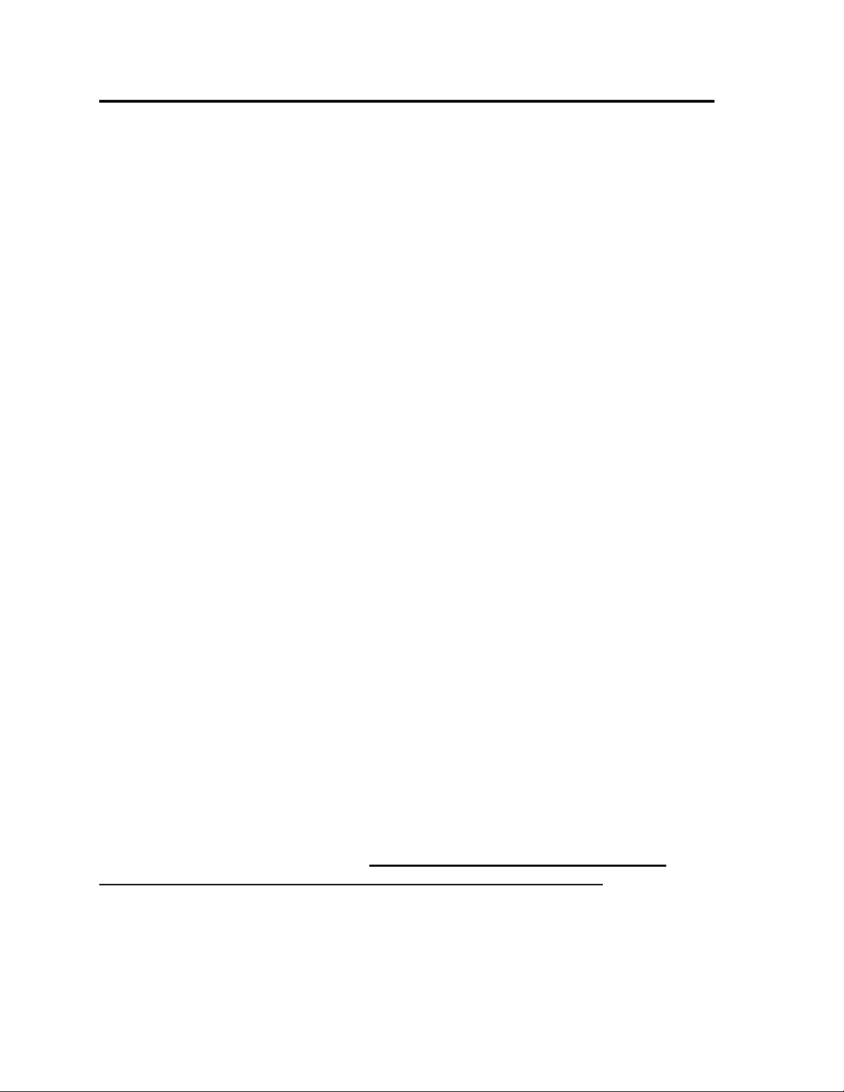
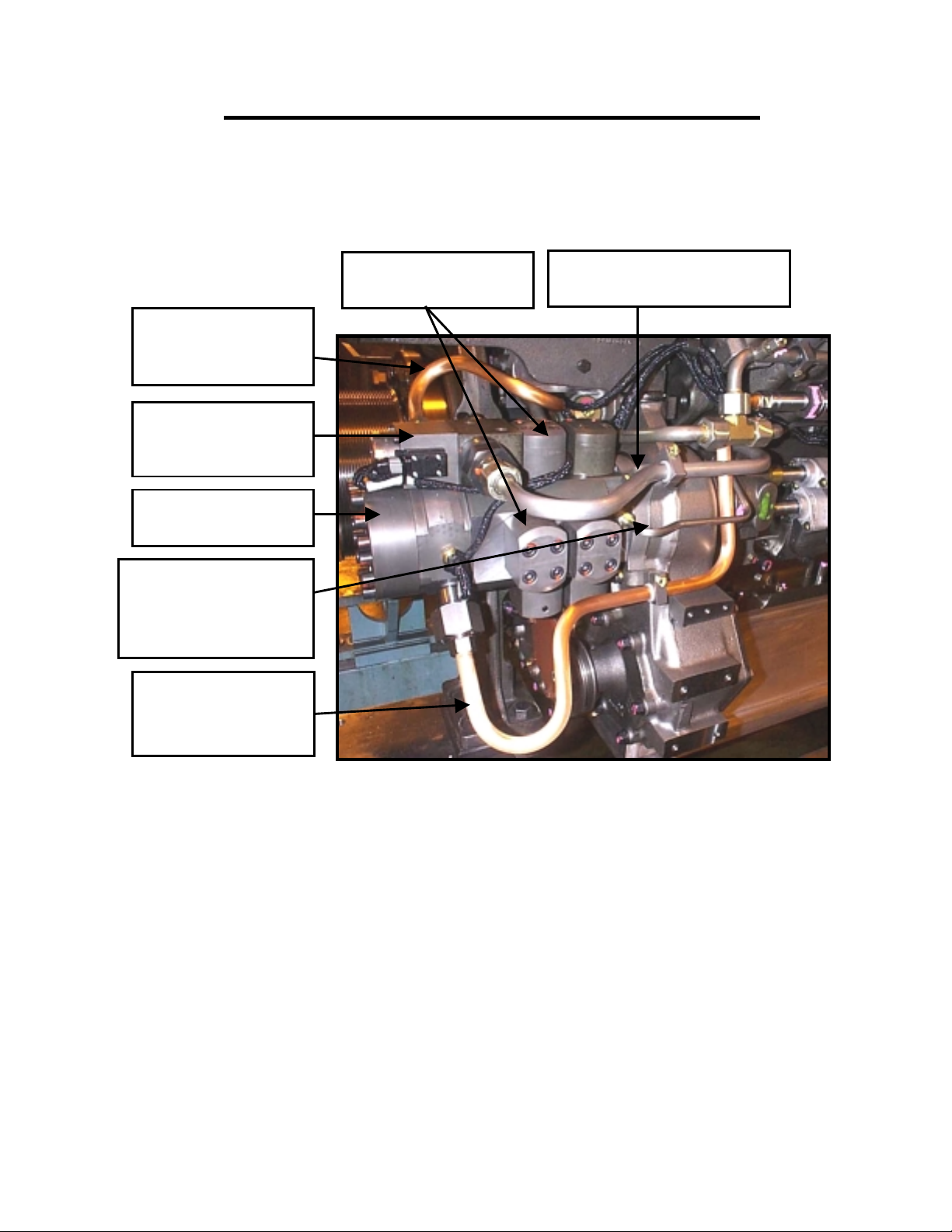
Common Rail Fuel System - A Bank
FUEL RETURN RAIL
Description of Fuel System
HIGH PRESSURE
INJECTOR FUEL
LINE
HIGH-PRESSURE FUEL
LINE TO B BANK RAIL
HIGH-PRESSURE FUEL
PUMP CONTROLLER
SOLENOID
HIGH-PRESSURE
HIGH-
FUEL PUMP
PRESSURE
LOW-PRESSURE FUEL
SUPPLY LINE FROM
FUEL JUNCTION
BLOCK TO HP PUMP
CONTROL SOLENOID
HIGH-PRESSURE
PUMP CONTROL
SOLENOID
Fig. 1
HIGH-PRESSURE FUEL
LINE TO A BANK RAIL
LOW-PRESSURE FUEL DELIVERY PUMP
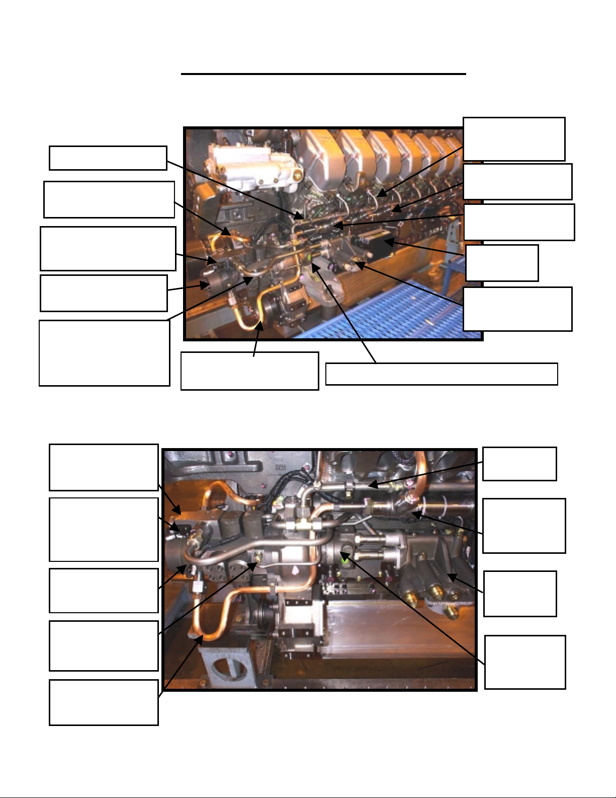
Fuel Delivery System - A Bank
HIGH-PRESSURE
FUEL RAIL
FLOW LIMITER
VALVE LOCATION
ECM COLD
PLATE (S)
FUEL JUNCTION
BLOCK AND
FILTER ADAPTOR
RETURN
FUEL RAIL
DDEC
CONNECTION TO
HIGH-PRSSURE
PUMP CONTROL
LOW-PRESSURE
FUEL SUPPLY TO
HP PUMP
HP PUMP RETURN
FUEL TO FUEL
JUNCTION BLOCK
HIGH-PRESSURE
FUEL LINE TO A
Page 3
BANK RAIL
Fig. 2
HIGHPRESSURE
FUEL RAIL
CONNECTOR
FUEL
JUNCTION
BLOCK
LOWPRESSURE
DELIVERY
FUEL PUMP
Page 12
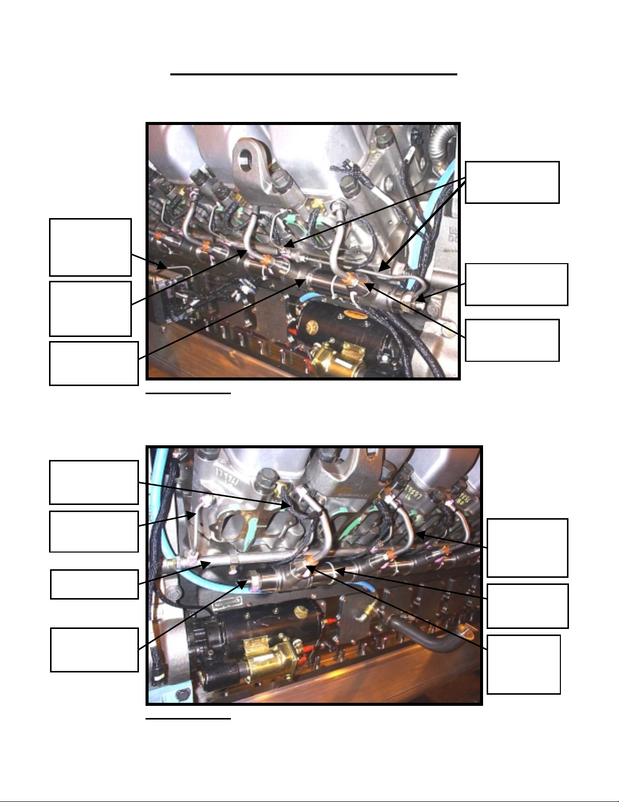
U
V
OC
ECM COLD
PLATE
CROSSOVER LINE
HIGHPRESSURE
INJECTOR
FUEL LINE
HIGHPRESSURE
FUEL RAIL
Description of Fuel System
High-pressure Rail - A Bank
FUEL RETURN
LINES TO FUEL
RET
RN RAIL
HIGH-PRESSURE
RAIL RELIEF
ALVE
FLOW LIMITER
VALVE
L
ATION
Rear of Engine Fig. 3
High-pressure Rail B Bank
DDEC WIRING
HARNESS TO
INJECTOR
INJECTOR
FUEL RETURN
FUEL
HIGHPRESSURE
RAIL END
Rear of Engine Fig. 4
Page 4
HIGHPRESSURE
NJECTOR
I
FUEL LINE
HIGHPRESSURE
FUEL RAIL
FLOW
LIMITER
VALVE
LOCATION
Page 13
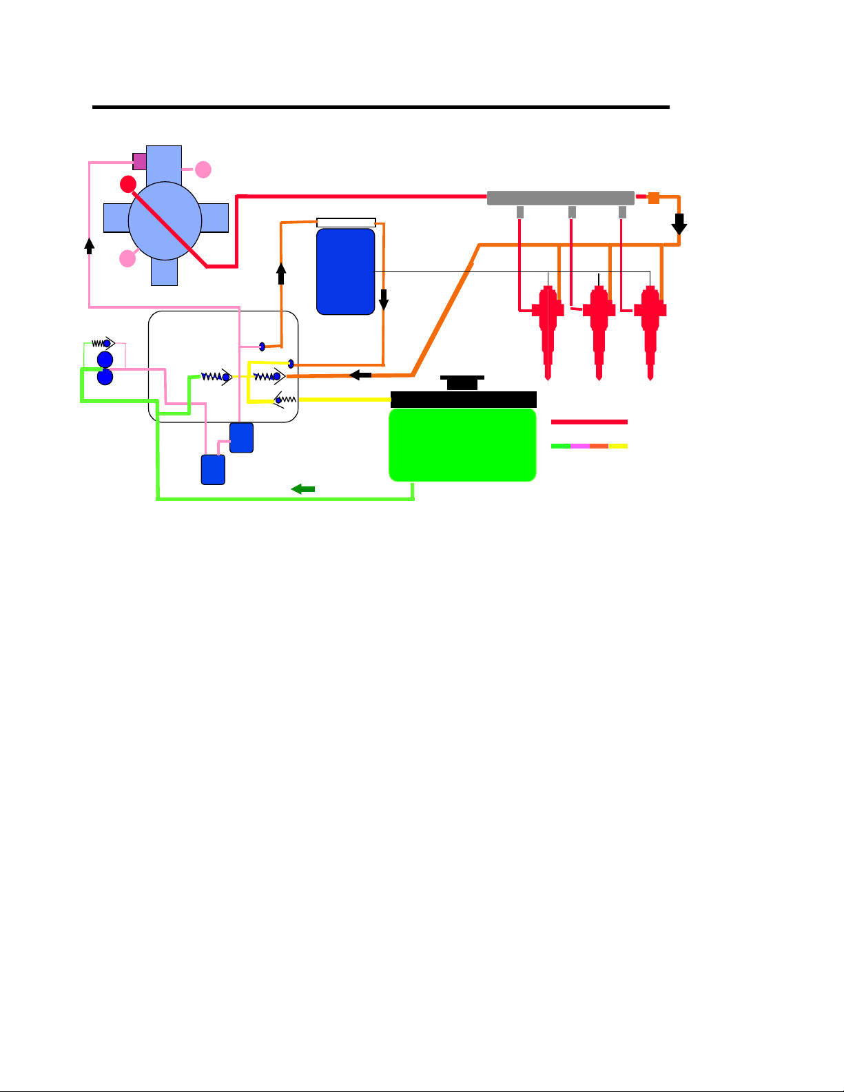
Com m on Rail Fuel System Operation
Limiter Safety
Limiting Safety
Valve 19.6 KPSI
Valve 1350 Bar
HP
LP
Common Rail
6.8 Bar
LT
High
Pressure
Pump
Fuel filter
Housing
1.7 Bar
2.0 Bar
DDEC IV
DDEC IV
ECM
ECM
Flow
Limiter
Injecto rs
.1 Bar
Fuel filters
Pro 40
Fuel Tank
The Common Rail Fuel System used on the Series 4000 is a two-stage fuel
distribution system. Gear driven fuel pumps maintain constant fuel supply
pressure. This pressure is supplied to the common rails then to all injectors.
Constant high-pressure is available regardless of crankshaft position or engine
speed.
The first stage is the fuel transfer side which brings fuel from the fuel tank,
through the filters, and provides low-pressure fuel supply of 65 PSI at idle to 85 PSI
at full load to the second stage high pressure system. Additionally, low-pressure
fuel is sent to the ECM Cold Plates to protect the ECM's from excessive heat (Refer
to page 63). An OEM supplied fuel cooler should be incorporated in the fuel system
to assist the cooling function for the ECM’s. Additionally, low-pressure fuel is used
for cooling and lubrication in the high-pressure fuel pump. However, unlike other
fuel systems, fuel temperature has no affects on engine power or performance due
to the extremely high fuel operating pressure, which prevents the fuel from boiling
and vaporizing.
The high-pressure system receives the low-pressure fuel at the control
regulator and further pressurizes it in the high-pressure pump from (8.3 KPSI at
idle to 17.4 KPSI) for non-low flow injectors and (7.25KPSI at idle to 13.1KPSI) for
low flow injectors at maximum load conditions to the high-pressure rails. (Refer to
page 17). Fuel pressure at Full No-Load averages about 11.4 KPSI. A 19.6 KPSI
safety-relief valve on the A-bank rail protects the fuel system components from
damage due to excessive pressure.
Page 5
H. Pr Line
L. Pr Line
Fig. 5
Page 14
Common Rail Fuel System Operation
High-pressure fuel as received at each injector provides lubrication and
cooling of the injectors while awaiting the DDECIV signal from the ECM’s to the
injector solenoid to start the injection event. Approximately 90% of the fuel
received at the injectors is injected into the engine cylinder for combustion, while
10% of the fuel is returned to the fuel tank under full load conditions.
Washer
Inlet Filter
Retaining Nut
C-E Ring
Fig. 6
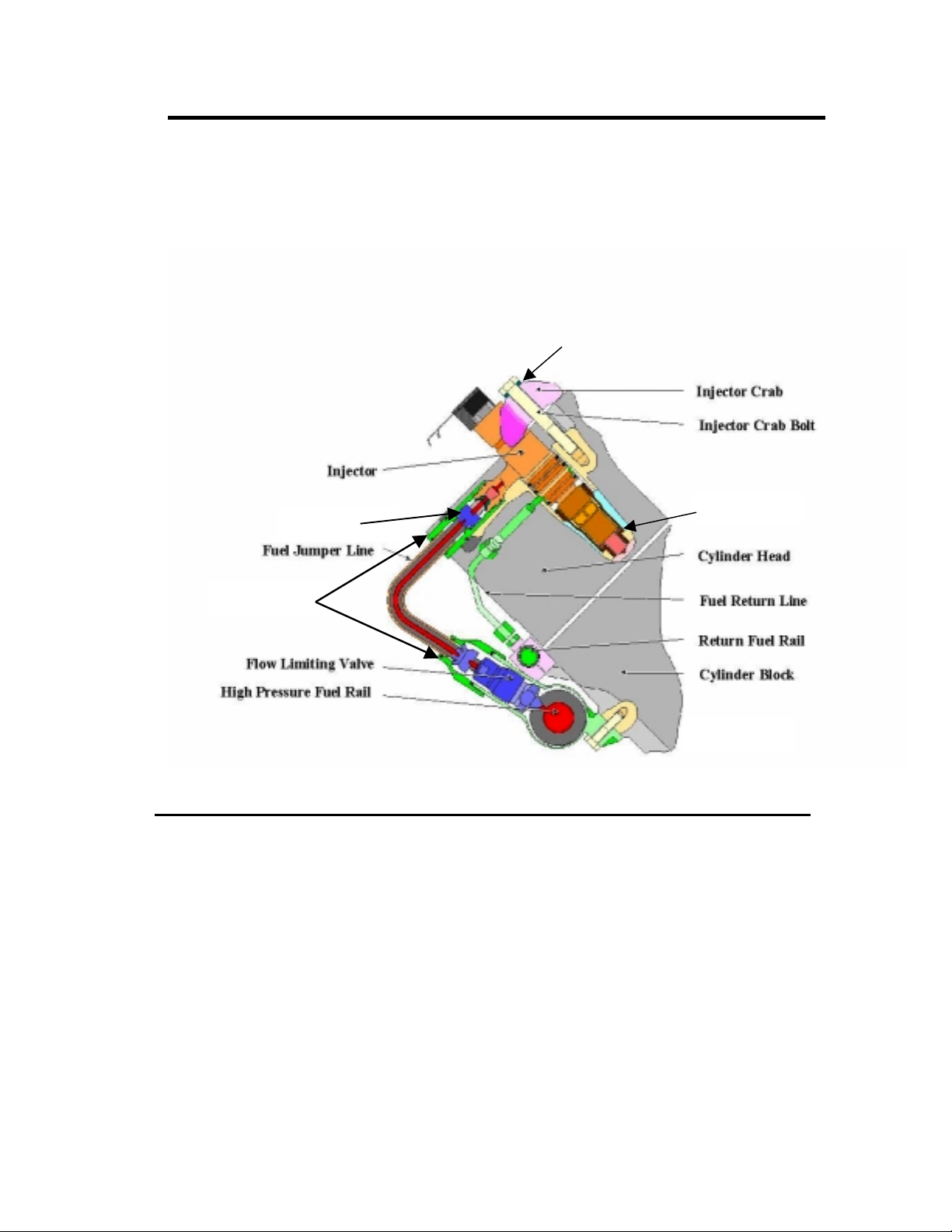
CROSS SECTION VIEW OF FUEL SYSTEM AT CYLINDER HEAD
The high-pressure fuel rails provide continuous pressure at all times to all
injectors within the engine. The high-pressure fuel rail at each cylinder location is a
port, which is fitted with a flow-limiter valve. High-pressure fuel passes from the
stainless steel high-pressure rails through flow limiter valves to the injectors. The
flow limiter valves operate by sensing fuel flow differential, which can shut off the
flow of fuel to prevent excessive over fueling of a cylinder in the event of a faulty
injector (Refer to page 53).
All of the joints from the high-pressure rail to the flow limiter valves to the
injectors are conical shaped metal-to-metal sealing (Refer to page 37).
Page 6
Page 15
Common Rail Fuel System Operation
V
The high-pressure fuel line to the injectors is double walled with an air gap
between the stainless steel inner tube and the outer copper protective tube (Refer
to page 44). This air gap is also a vent from the injector providing early warning of
poor injector C-E Ring sealing. The injector has a vent hole drilled in the body from
below the lower O-ring land out through the injector arm to the high-pressure line
joint surface, which aligns with the air gap in the high-pressure fuel line (Refer to
page 31).
The injector is retained in the cylinder head hole tube by the injector hold
down clamp and retaining bolt. The clamp load provided by this hold down crab
and bolt works with the C-E Ring located at the injector nozzle to provide a
compression seal with the injector hole tube inner surface. The high-pressure
injector fuel line fittings are held in position to the tube by retaining nuts on each
end (Refer to page 44). These retaining nuts have reverse threads, which requires a
special tool for installation.
At the inlet of the injector, recessed in the arm, is an inlet filter screen. This
screen is a safety element intended to trap foreign material, which could find its
way to the injector. The injector assembly has three O-ring seals between the
injector body and the cylinder head to control the flow of the return fuel from the
injector into the cylinder head return passage (Refer to page 31). Unused fuel from
the injector exits the injector through the passage between the second and third Oring land into the return port in the cylinder head. The return fuel then passes
through the external return fuel line from the cylinder head to the return fuel rail
back to the fuel tank.
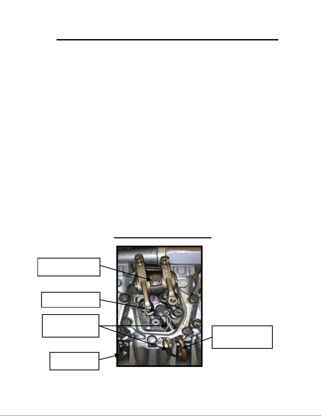
ALVE OPERATING
MECHANISM
ELECTRONIC UNIT
DDEC WIRING
HARNESS TO
INJECTOR
RETURN FUEL
LINE
Cylinder Head View
HIGH-PRESSURE
FUEL LINE TO
INJECTOR
Fig. 7 Injector Installation in Cylinder Head
Page 7
Page 16

Page 8
Page 17
Detroit Diesel Electronic Controls
Flow
Limiter
Rail
Pressure
Sensor
Common Rail
Pressure
Limiting
Valve
Fuel Tank
Injectors
Controlled High
Pressure Pump with
Pre-Supply Pump
Filter
Sensors
MDEC
DDEC IV
OR
DDEC IV
ECM
ECM
DDECI
V
Fig. 8
DDECIV electronics control the beginning of injection or timing of the event
and the duration of the injection event, which determines the amount of fuel being
injected. Timing of the injection event is totally a function of DDECIV and not that
of the camshaft lobe profile as in other fuel systems.
DDECIV sends a signal to the injector solenoid to inject fuel into the
cylinders. To provide this control, DDECIV electronics utilize state of the art
microprocessors to gather information from the engine and its operating
environment to be used in determining the optimum schedule of fuel injection.
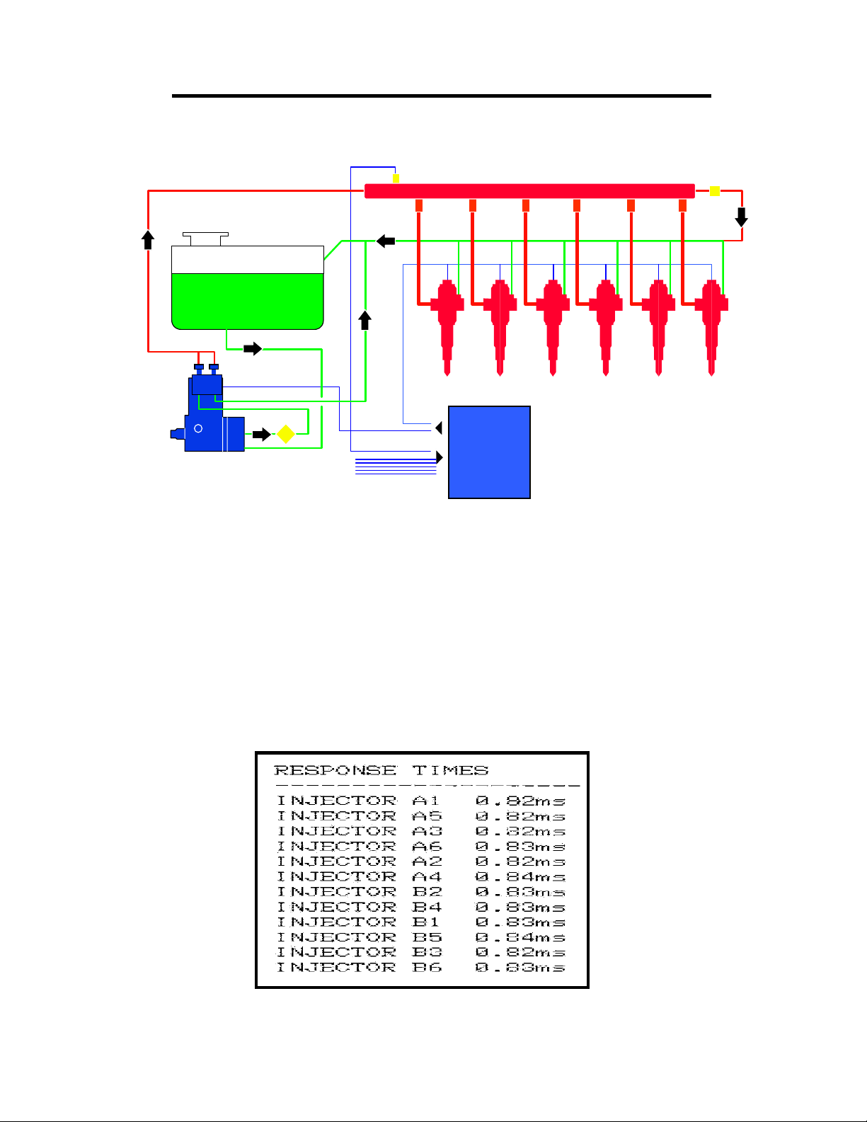
Part of the information gathered is from the fuel system itself. DDECIV receives
feedback for the injector solenoids as to their performance in the form of Response
Times as seen in the DDEC printout shown in Fig. 9.
Fig. 9 Injector Response Times Printout.
Page 9
Page 18
Detroit Diesel Electronic Controls
V
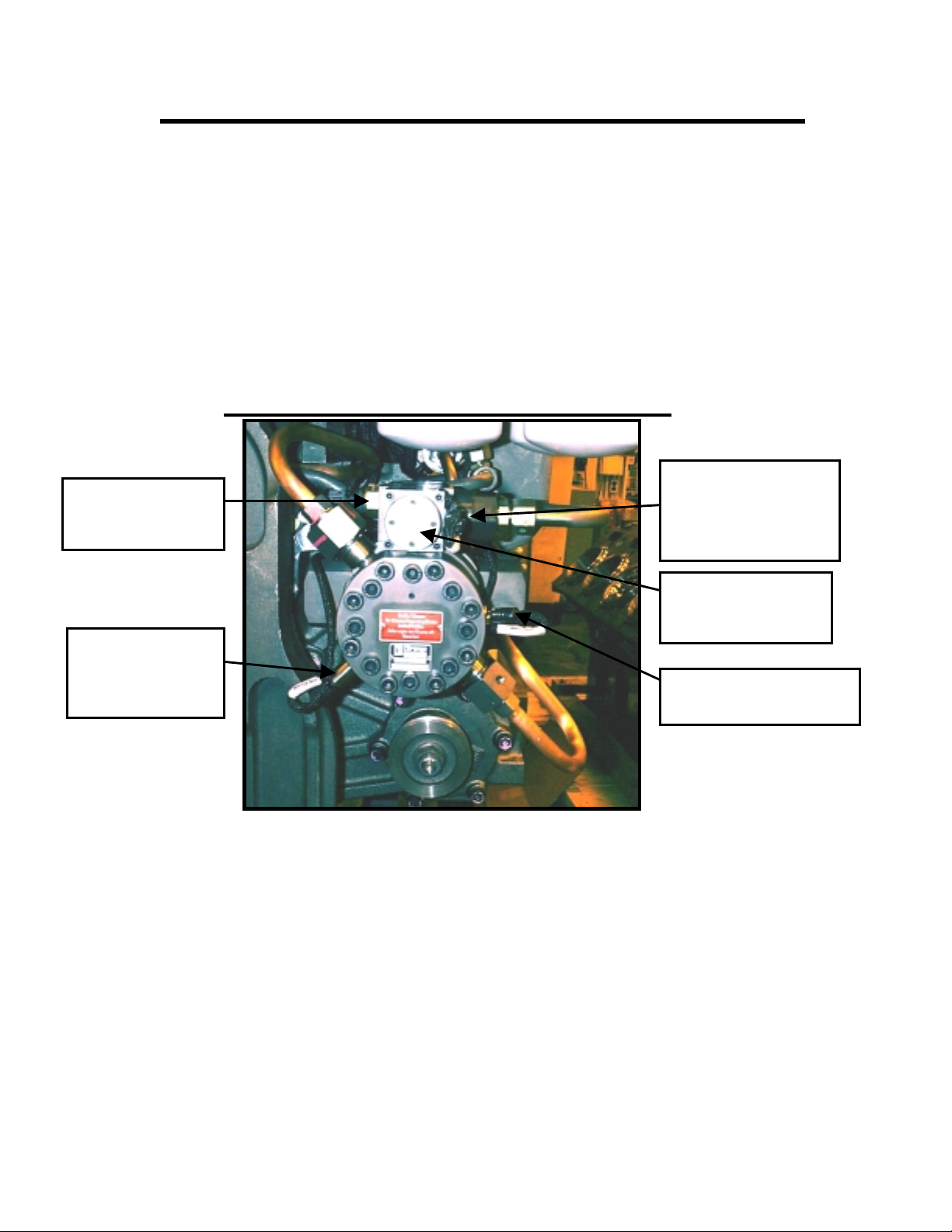
The Common Rail Fuel System consists of several sensors used to evaluate
its own performance. These sensors are; high fuel pressure, low fuel pressure and
fuel temperature, which are located on the high-pressure fuel pump as shown in
Fig. 10.
The low fuel pressure sensor provides information on the availability of lowpressure fuel being supplied to the high-pressure pump. The high fuel pressure
sensor provides information on the fuel pressure within the high-pressure rails
available for injection. The fuel temperature sensor provides information on the
temperature of the fuel being supplied to protect the ECM’s and high-pressure fuel
pump.
HIGH-PRESSURE FUEL PUMP
DDEC HARNESS
LOW-PRESSURE
FUEL PRESSURE
SENSOR
CONNECTION TO
HP PUMPCONTROL
SOLENOID (24-
OLT SUPPLY)
HIGH-PRESSURE
PUMP CONTROL
SOLENOID
HIGH-PRESSURE
FUEL RAIL
PRESSURE
SENSOR
FUEL TEMPERATURE
SENSOR
Fig. 10 High-pressure Pump Sensor Locations.
The high-pressure fuel pump receives low-pressure fuel from the fuel
delivery pump and controls the high-pressure fuel output with the control solenoid,
which receives input from the Master ECM and provides feedback information to
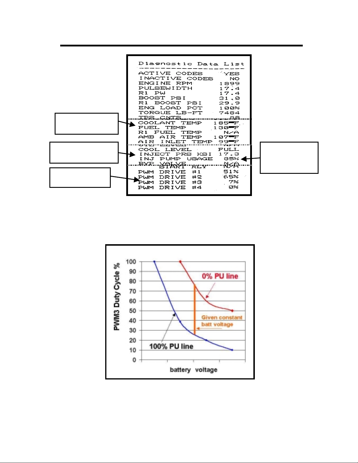
the Master ECM. This input and output can be read with a DDR as PWM3 and
Injection Pump Usage (Refer to Fig. 11).
The normal PWM3 operating range is 8-52%. Injection pump usage operates
between 2% and 98% range. The normal injection pump usage at 100% engine load
is in the 45-65% range at 1900 RPM. The control solenoid operates on 24 Volts DC
with a fuse located in the OEM supplied power circuit.
Page 10
Page 19
Detroit Diesel Electronic Controls
FUEL
TEMPERATURE
INJECTION RAIL
PRESSURE
PWM #3
PERCENTAGE
Fig. 11 Diagnostic Data List Printout.
HIGHPRESSURE
PUMP USAGE
Fig. 12 Relationship Between High-pressure Pump % (Percent) Usage and PWM3.
Page 11
Page 20
Detroit Diesel Electronic Controls
ELECTRONIC PILOT INJECTION (EPI)
Normal fuel injection has long ignition delays resulting in large quantities of
fuel to be injected before the beginning of combustion. With large amounts of fuel
at the beginning of combustion, there is a high rate of cylinder pressure rise, white
smoke from unburned fuel and excessive combustion noise.
DDEC controlled Electronic Pilot Injection (EPI) provides a small quantity of
fuel injection in advance of the normal injection beginning the combustion
process. This is followed by the main quantity of fuel injection to complete
combustion. EPI is a form of indirect injection reducing the ignition delay period
thereby reducing the rate of pressure rise effectively reducing the unburned fuel
and cylinder knock during startup.
Significant reduction in fuel consumption, peak cylinder pressure, rate of
pressure rise and emissions are all achieved with EPI.
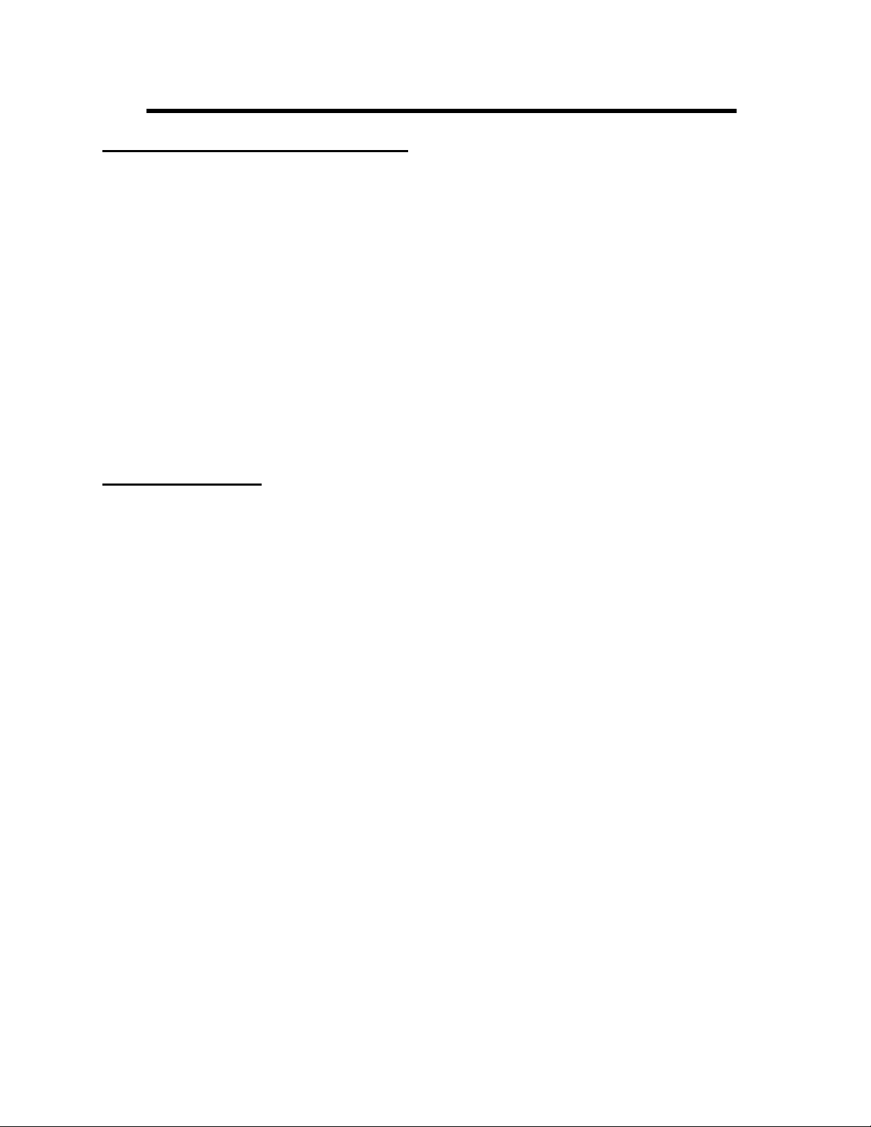
HALF ENGINE IDLE
The half engine idle feature controlled by DDEC enables the engine to
maintain higher cylinder temperature during idle to light load operating conditions.
Half engine idle is activated depending on the percent of load, air intake
temperature and engine coolant temperature. Half engine operation may occur up
to 1900-rpm engine speed.
Half engine operation differs with the 12V4000 from the 16V4000 models on
the 12V, only the master ECM fires the “A” bank cylinders; with the 16V, both
ECM’s control (4) cylinders each for either bank randomly.
Page 12
Page 21
Detroit Diesel Electronic Controls
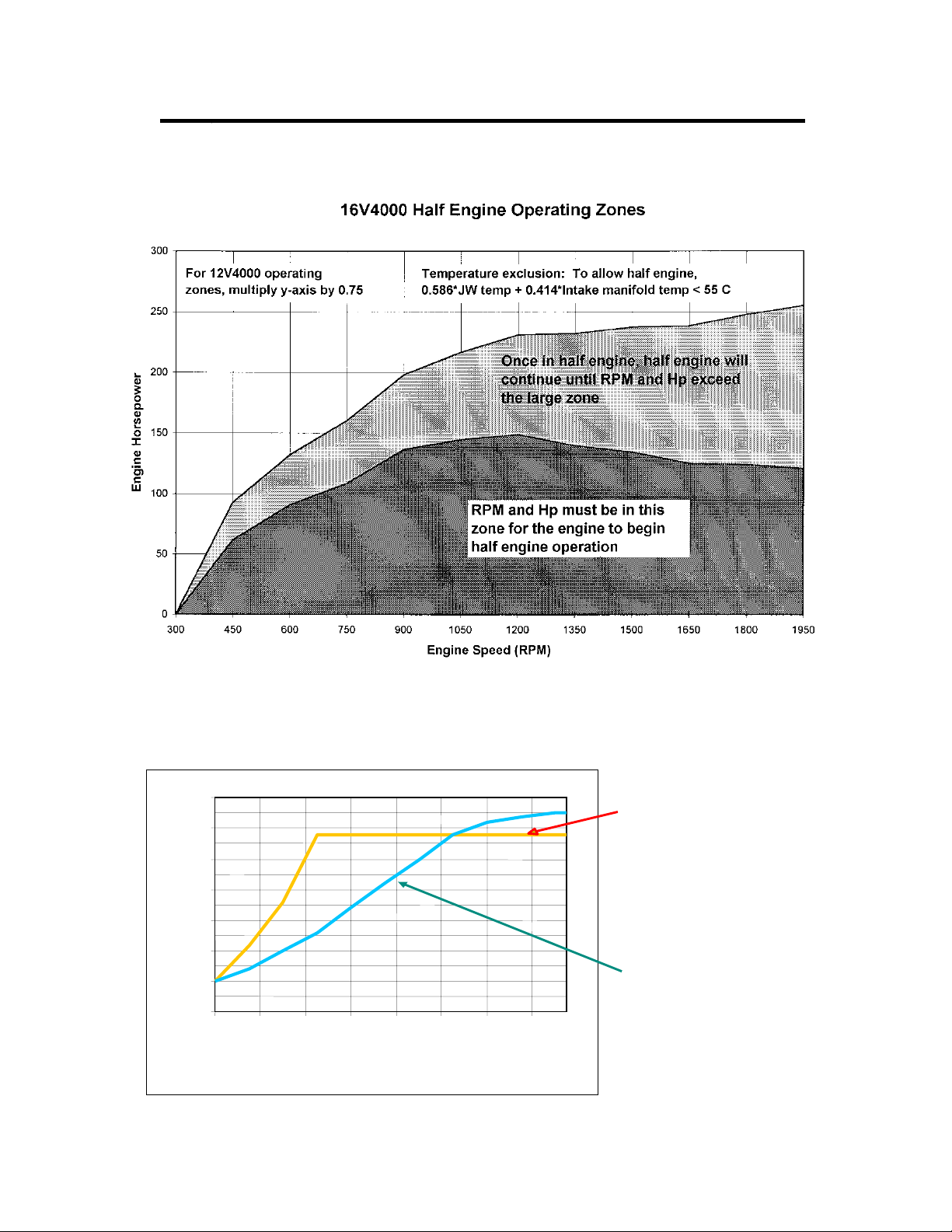
Fig. 13
Series 4000 Low Pressure Fuel Limits
70
60
PSI
50
40
30
20
10
0
450 650 850 1050 1250 1450 1650 1850
Engine Speed
Fuel pressure drop Max
CEL activated
Max Fuel Temperature 140F
CEL activates.
Oil pressure
Fig. 14
Page 13
Page 22

Page14
Page 23
COMPONENT REVIEW INDEX
Page
• HIGH-PRESSURE FUEL PUMP 17
• LOW-PRESSURE FUEL DELIVERY PUMP 25
• ELECTRONIC UNIT INJECTOR 31
• FUEL RAILS AND LINES 37
• FLOW LIMITER VALVES 53
• C&I FUEL JUNCTION BLOCK AND
SECONDARY FUEL FILTERS 57
• MARINE SECONDARY FUEL FILTERS 61
• ECM COLD PLATE (S) 63
• FUEL LEAK MONITOR SYSTEM (MARINE) 65
• DDEC SENSORS 67
Page 15
Page 24

Page 16
Page 25
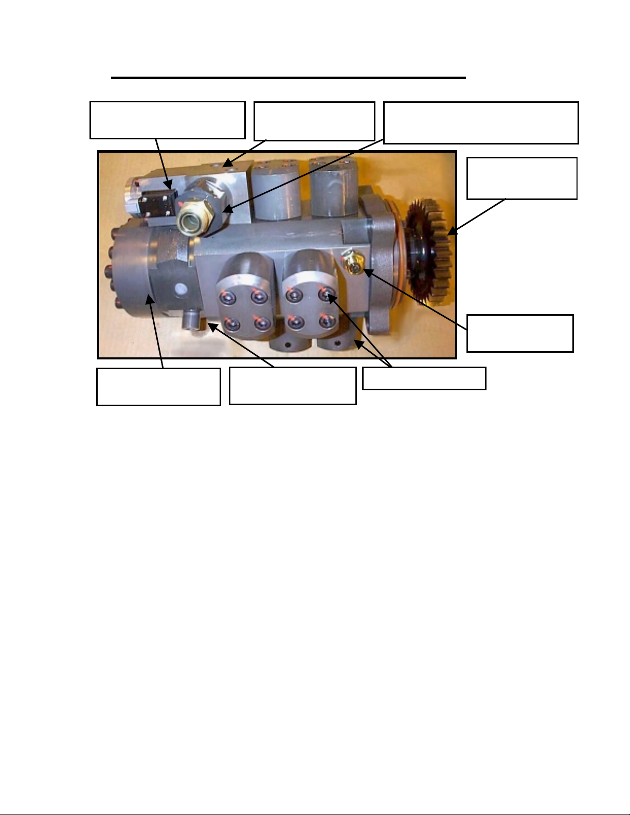
HIGH-PRESSURE FUEL PUMP
SO
The high-pressure fuel pump is mounted on the front side of the gear
case and is driven by the A-bank idler gear. The high-pressure pump utilizes a
break away driven gear, which disengages itself in the event of a pump failure to
prevent engine gear train damage.
HIGH-PRESSURE
RAIL SUPPLY
LINE, B-BANK
HIGH-PRESSURE
PUMP CONTROL
LENOID
HIGH-PRESSURE
PUMP
HIGH-PRESSURE
PUMPING UNITS
LOW-PRESSURE FUEL
SUPPLY LINE
HIGH-PRESSURE
PUMP BODY FUEL
RETURN LINE TO
JUNCTION BLOCK
HIGH-PRESSURE
RAIL SUPPLY
LINE, A-BANK
Fig. 15 High-pressure Fuel Pump Installation.
The high-pressure pump receives filtered low-pressure fuel from the fuel
delivery pump at the control solenoid. The high-pressure pump control solenoid
meters the amount of fuel entry to the high-pressure pump body and pumping
units. The control solenoid is 24 volt operated to close against spring pressure in
the open direction. (See Page 23).
Part of the fuel received by the high-pressure pump passes to the pump
crankcase where it provides lubrication and cooling to the pump camshaft
bearings and ceramic rings. The lubrication and cooling fuel exits the highpressure pump body by a fuel return line to the fuel junction block (See Fig. 15).
Page 17
Page 26
HIGH-PRESSURE FUEL PUMP
24-VOLT POWER
SUPPLY CONNECTOR
HIGH-PRESSURE
ACCUMULATOR
Fig. 16 High-pressure Fuel Pump Assembly
The majority of the fuel entering the high-pressure pump is directed to high
pressure pumping units for pressurization to the required operating pressure.
There are eight pumping units shown in Figure 16, which are operated by the
eccentric camshaft rings and controlled by inlet and outlet check valves. Fuel
enters the pumping unit through the inlet check valve, pressurized by the piston to
the high operating pressure, then exits through the outlet check valve to the
accumulator. There are two high-pressure outlet ports for transferring the
pressurized fuel to both the A-bank and B-bank high-pressure rails.
REGULATOR
VALVE
HIGH-PRESSURE
FUEL OUTLET
Page 18
LOW-PRESSURE FUEL INLET
CHECK VALVE AND FILTER
DRIVEN GEAR
(BR EAK AWAY)
FUEL RETURN
PORT
PUMPING UNITS
Page 27
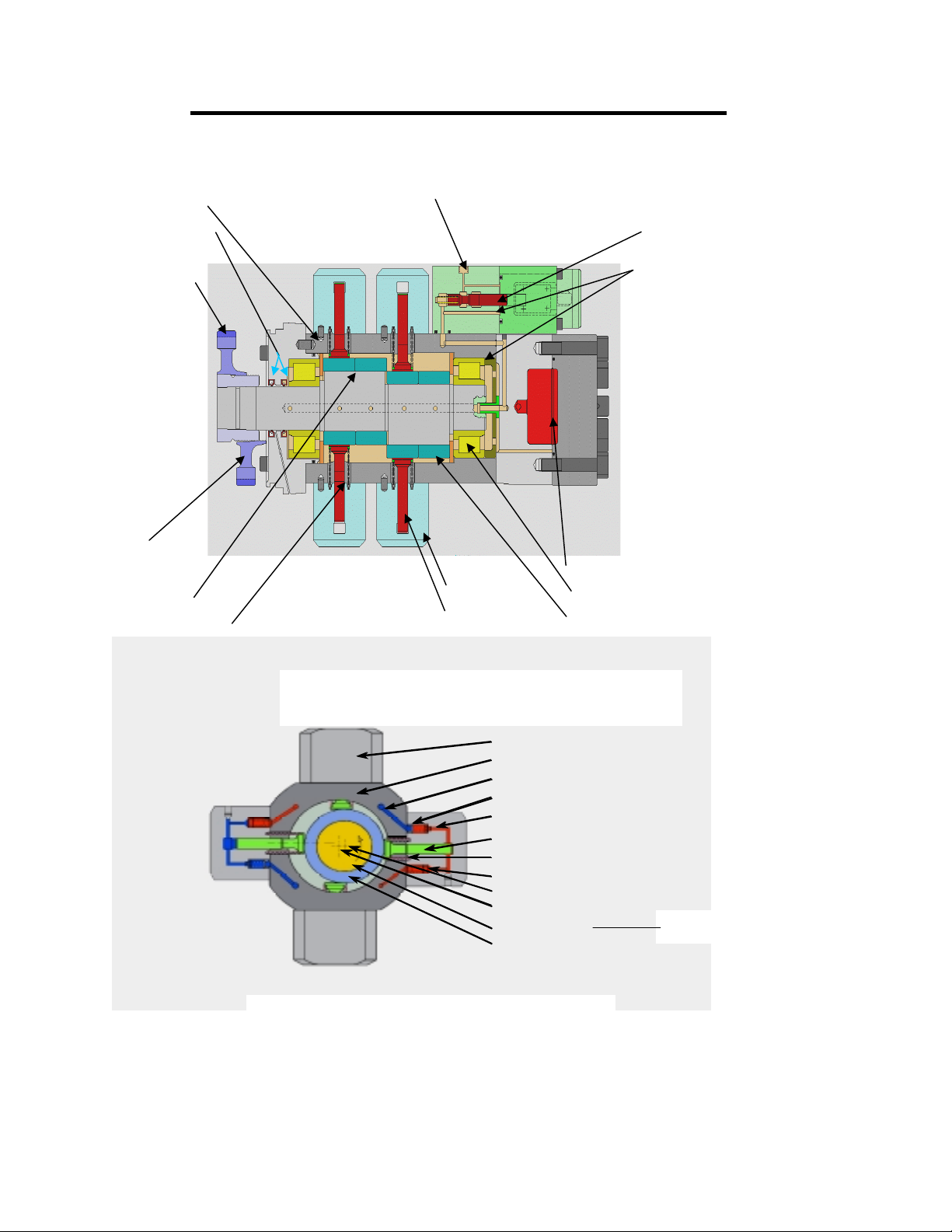
HIGH-PRESSURE FUEL PUMP
CRANKCASE FUEL INLET
SHAFT SEALS
DRIVE GEAR
ENGAGED
HIGH PRESSURE
REGULATOR VALVE
COOLING AND
LUBRICATING FUEL
DRIVE GEAR
DISENGAGED
ECCENTRIC
PISTON SPRING
CYLINDER
PISTON
SIDE CUT AWAY VIEW
CYLINDER
CRANKCASE
SUPPLY FUEL
CHECK VALVE INLET
HIGH PRESSURE FUEL
PISTON
FOLLOWER SPRING
CHECK VALVE OUTLET
CENTER OF CAM
CENTER OF CRANK
CAMSHAFT
CERAMIC BEARING
HIGH PRESSURE ACCUMULATOR
CRANKSHAFT BEARING
CERAMIC BEARINGS
(Fig. 17)
(ECCENTRIC)
END CUT AWAY VIEW
Page 19
(Fig. 18)
Page 28

Page 20
Page 29
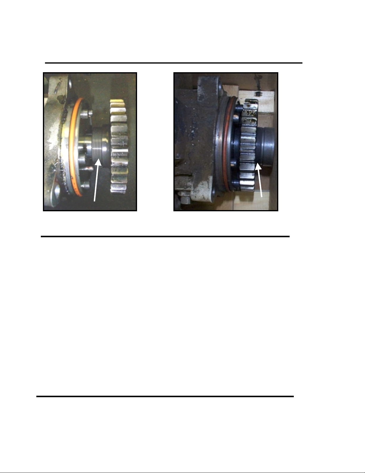
INSPECTION AND ANALYSIS
HIGH-PRESSURE FUEL PUMP
Fig. 19 Normal Gear Position Fig. 20 Disengaged Gear Position
CONDITION:
CAUSE:
restriction, which starved the high-pressure pump causing a lack of
lubrication or cooling condition.
RECOMMENDATION:
fuel system cleaning procedure in Maintenance Section. Evaluate fuel
system for source of low-pressure fuel flow restriction.
REUSE:
NOTICE: Do not disassemble the high-pressure fuel pump for any reason!
Do Not Reuse!
If the pump fails to rotate, replace the pump assembly. All highpressure fuel pumps are to be returned intact as Reliabilt® cores.
High-pressure pump seized, drive gear disengaged.
High-pressure fuel pump bearing failure. Low-pressure fuel flow
Replace High-pressure pump assembly and follow
Page 21
Page 30
INSPECTION AND ANALYSIS
HIGH-PRESSURE FUEL PUMP
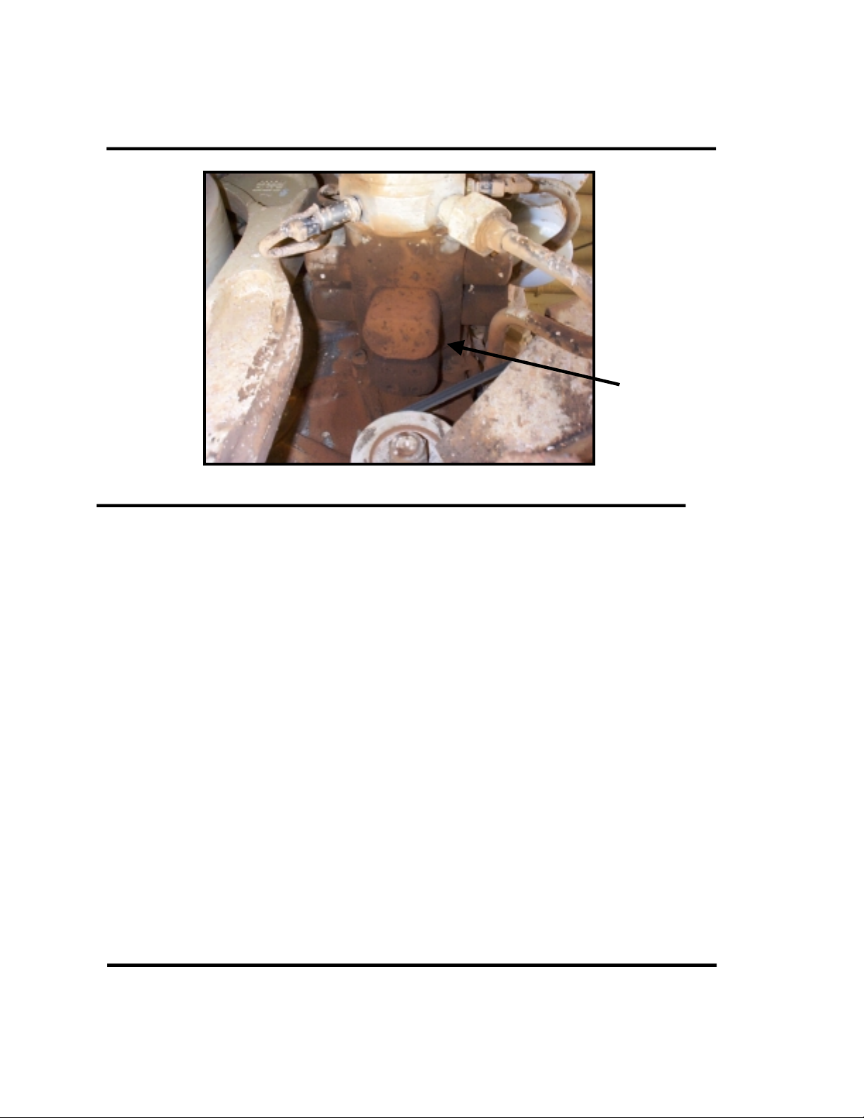
Fig. 21 High-pressure Fuel Pump Leak at Weep hole.
CONDITION:
pump weep hole is acceptable for service. Continuous dripping at the weep
hole would define a leak and require servicing.
CAUTION: Presence of excessive amount of diesel fuel could present a
safety hazard and should be addressed immediately.
CAUSE:
contaminates can contribute to this cause. Excessive fuel temperature or
dry operation of the pump may also result in seal damage.
RECOMMENDATION:
condition and condition of equipment fuel system for con tr ibuting factors.
Review events of dry operation and priming procedures being used.
REUSE:
NOTICE: Do not disassemble the high-pressure fuel pump for any reason!
All high-pressure fuel pumps are to be returned intact as Reliabilt® cores.
Do Not Reuse!
High-pressure pump leak at weep hole. A damp area at the
Pump drive shaft pump body seal leaking. Fuel system
Replace High-pressure pump assembly. Evaluate fuel
Page 22
Page 31

HIGH-PRESSURE FUEL PUMP
V
V
V
V
V
REGULATOR VALVE ASSEMBLY
SOLENOID
SOLENOID
ARMATUR
SOLENOID
COIL
Fig. 22
24-VOLT POWER
SUPPLY CONNECTOR
Low-pressure fuel is received at the control-valve fuel inlet port. The control
valve plunger is spring actuated in the full fuel position when 24-volt power supply
is not present at the solenoid. Depending on the supply voltage received, the
solenoid armature acts against the control valve plunger and spring to move to the
desired fuel inlet flow rate past the control valve determined by DDEC.
CONTROL-
ALVE
CONTROL-VALVE
FUEL INLET PORT
CONTROL
ALVE BODY
CONTROL-
ALVE SPRING
CONTROLVALVE BODY
SOLENOID
ASSEMBLY
Fig. 23
CONTROL-
ALVE
The regulator valve assembly is made up of the solenoid assembly and the controlvalve body assembly, which includes the control valve plunger and control valve
spring. Only the solenoid assembly is serviced separately from the complete
regulator valve assembly.
CONTROL-
ALVE SPRING
Page 23
Page 24
Page 32

Page 33

LOW-PRESSURE FUEL DELIVERY PUMP
LOW-PRESSURE
FUEL PUMP
INLET PIPE
Fig. 24
LOW-PRESSURE
FUEL DELIVERY
PUMP
The low-pressure fuel delivery pump receives fuel from the fuel junction
block through the low-pressure pump inlet pipe. The fuel is then pressurized by
the low-pressure fuel delivery pump to a normal operating pressure range of 64 PSI
to 85 PSI at rated speed. The pressurized fuel is then sent to the fuel junction
block via the low-pressure fuel pump outlet pipe. The fuel junction block directs
the low-pressure fuel through the primary and secondary fuel filter to the supply
line providing low-pressure fuel to the high-pressure fuel pump regulator valve
assembly inlet port.
LOW-PRESSURE
FUEL PUMP
OUTLET PIPE
Page 25
FUEL JUNCTION
BLOCK
Page 34

LOW-PRESSURE FUEL DELIVERY PUMP
case housing and is gear driven from the rear of the A-bank idler gear behind the
high-pressure pump drive. The delivery pump is a gear type mechanical pump
utilizing a drive gear with shaft and a driven gear in a two-piece housing (Fig. 26).
Pressurized fuel is regulated by a pressure regulator valve and spring mounted in
the pump cover (Fig. 25). The maximum pressure is regulated to 105-PSI output.
The body and cover of the fuel pump contain support bearings for the drive and
driven gears (Fig. 27).
PRESSURE
REGULATOR
VALVE
Fig. 25
WEEP HOLE
The low-pressure fuel delivery pump is mounted on the backside of the gear
PUMP DRIVE
DRIVEN GEAR
Fig. 26 Fig. 27
DRIVE GEAR
PUMP COVER SUPPORT BEARINGS
Page 26
Page 35

LOW-PRESSURE FUEL DELIVERY PUMP
V
V
V
There are two seals on the drive gear shaft (Fig. 28). The inner seal is used
to retain fuel in the pump from leaking past the drive sha ft into the engine. The
outer seal prevents engine oil from entering the fuel system through the fuel pump.
There is a small weep hole located in the pump body to allow for drainage and early
warning should either seal begin to leak (Refer to Fig. 25).
SPRING SET
REGULATOR
ALVE SPRING
Fig. 28 Fig. 29
SHAFT SEAL
REGULATOR
ALVE
Page 27
REGULATOR
ALVE BORE
PLUG
18
Page 36

Page 28
Page 37

INSPECTION AND ANALYSIS
LOW-PRESSURE FUEL PUMP
Fig. 30 Low-pressure fuel leak at weep hole.
CONDITION:
pump weep hole is acceptable for service. Continuous dripping at the weep
hole would define a leak and require servicing.
CAUTION: Presence of excessive amount of diesel fuel could present a
safety hazard and should be addressed immediately.
CAUSE:
contaminates can contribute to this cause. Excessive fuel temperature or
dry operation of the pump may also result in seal damage.
RECOMMENDATION:
condition and condition of equipment fuel system for con tr ibuting factors.
Review events of dry operation and priming procedures being used.
REUSE:
NOTICE: Do not disassemble the Low-pressure fuel pump for any reason!
If the pump fails to rotate, replace the pump assembly. All Low-
pressure fuel pumps are to be returned intact as Reliabilt® cores.
Low-pressure pump leak at weep hole. A damp area at the
Pump drive shaft pump body seal leaking. Fuel system
Replace Low-pressure pump assembly. Evaluate fuel
Do Not Reuse!
Page 29
Page 38

Page 30
Page 39

ELECTRONIC UNIT INJECTOR
Solenoid
Control Valve
Control Unit
O-RINGS
High Pressure Fuel
Inte rmed ia te V a lv e
Body
Filter
Vent
Sleeve
Rod
Fuel Return
Needle Valve
Nut
Nozzle
Fig. 31 Injector Assembly (Cutaway)
The Electronic Unit Injector delivers the fuel input into each cylinder.
The unit injector receives high-pressure fuel continuously from the highpressure rails. The unit injector does not need to make pressure, therefore,
there is no camshaft driven mechanism requiring adjustment or tune-up. The
amount of fuel and timing is controlled by DDECIV.
DDECIV controls the fuel flow in the injector by sending a signal to the
injector solenoid. The control valve is spring loaded in the closed position
and opens when the solenoid is energized. Each injector has its own
calibration code, which is factory determined and stamped on the injector
identification plate (Fig. 32 and Fig. 33). The calibration code can be any
number from 00 to 99 (Fig. 34). The calibration code is entered into DDECIV
with the DDR reader or DDDL, so that DDECIV can balance each injector for
uniform fuel output and performance.
Page 31
Page 40

ELECTRONIC UNIT INJECTOR
INJECTOR
INJECTOR NAME
PLATE WITH
CALIBRATION CODE
Fig. 32 Fig 33 Fig. 34
The energized solenoid lifts the control valve, which hydraulically
permits the rod to rise and the needle to lift from its seat. This action allows
fuel to flow from the injector tip into the combustion chamber. To end
fueling the solenoid is de-energized, allowing the control valve to fall against
the control unit, which causes hydraulic pressure to build above the rod
forcing it and the needle downward until the needle closes against its seat.
About 10% of the fuel, which entered the unit injector is used for
lubrication and cooling, exits the injector through the fuel return port. The
fuel return port is located between the second and third o-ring lands on the
injector body (Fig. 35). The return fuel exits the injector from the fuel return
port to a port in the cylinder head to the return fuel line to the return
manifold.
INJECTOR
ASSEMBLY
RETURN
FUEL PORT
INJECTOR
HOLE TUBE
(CUT AWAY)
C-E RING
Page 32
INJECTOR HOLD DOWN
BOLT AND WASHER
INJECTOR HOLD
DOWN CLAMP
CYLINDER HEAD
COOLANT PASSAGE
Fig. 35
Page 41

INSPECTION AND ANALYSIS
ELECTRONIC UNIT INJECTOR
O-RINGS
FUEL
RETURN
PORT
Fig. 36 NEW Fig. 37 HEAVY CARBONED FROM
FAILED C-E RING
CONDITION:
Injector damaged from compression and carbon. O-ring
damage can occur from combustion heat, which could result in return fuel
leaking past the o-rings into the engine oil or compression entering the return
fuel.
CAUSE:
Leaking C-E Ring. May be defective C-E Ring or a loose or broken
hold down bolt.
RECOMMENDATION:
Inspect injector hole tube for damage. Replace Injector
Assembly with new C-E Ring and o-rings. Insure proper hold down bolt
torque is used.
REUSE:
Do Not Reuse!
Page 33
Page 42

INSPECTION AND ANALYSIS
(
INJECTOR C-E RING
CARBON BUILD-UP
C-E RING
COPPER)
C-E RING (FORMER
STYLE STEEL)
Fig. 38 NORMAL
LEAKING COMBUSTION
Fig. 39 (FORMER STYLE TWO PIECE)
CONDITION
injector body and injector hole tube. Carbon will also in injector vent
passage and high-pressure fuel line. Injector O-rings may be burnt and
damaged. Injector hole tube may also be damaged from combustion gases.
CAUSE:
down bolt or defective C-E Ring.
RECOMMENDATION:
Inspect hold-down bolt and clamp. Replace if needed. Replace Injector hole
tube.
REUSE:
or high pressure fuel line. Replace both as the vent passage is plugged with
carbon.
Page 34
: C-E Ring leaking combustion causing carbon build-up on
Improper hold-down clamp bolt torque or missing washer on hold-
Replace Injector assembly, C-E Ring and O-rings.
If carbon is present in high-pressure fuel line, do not reuse injector
Page 43

INSPECTION AND ANALYSIS
CYLINDER HEAD FUEL INJECTOR TUBE
O-RING OVERHEATED
Fig. 40 Fig. 41 Fig. 42
NORMAL OPERATION OPERATION WITH C-E RING
WITH C-E RING OMITTED
SE AT AR EA
CONDITION:
Build-up in the tube and coolant leak from overheated injector tube o-ring.
CAUSE:
RECOMMENDATION:
area. Severe carbon buildup will require the replacement of the tube and orings. Clean thoroughly, insure C-E Ring seat area is flat and free of carbon.
REUSE:
are used when injector is installed.
Page 35
Combustion leaking into injector tube area causing carbon
C-E Ring was omitted during injector installation.
Inspect for signs of erosion inside tube area at seat
Replace injector tube if C-E ring has failed. Insure new C-E Rings
Page 44

INSPECTION AND ANALYSIS
FUEL INJECTOR HOLD-DOWN CLAMP & BOLT
BOLT HEAD
SE AT AR EA
ON HOLDDOWN CLAMP
BROKEN
HOLD-DOWN
BOLT
NORMAL
Fig. 43 Injector Hold-down Bolt Failure
CONDITION: Broken hold-down bolt.
CAUSE: Excessive torque during installation.
RECOMMENDATION: Replace bolt and add new hardened washer. Follow proper
torque specifications shown in the Torque Specifications section.
REUSE: Do not reuse! Inspect hold-down clamp bolt head seat area for signs of
fretting. If fretting is present, replace bolt even if bolt is not broken. Fretting is a
sign of the bolt working from possible being stretched, which could result in a
broken bolt and loss of clamp load on the injector. Replace the hold-down clamp if
it is severely fretted.
Page 36
Page 45

FUEL RAILS AND LINES
Fig. 44 Common Rail Fuel System
The rails of the Common Rail Fuel System include the high-pressure and the
low-pressure return rails. The high-pressure rails are of stainless steel
construction with port locations for each fuel limiter valve seat (Fig. 45). The front
of the high-pressure rails has fittings to accept a high-pressure fuel line. The rear
of the high-pressure rail is fitted with a safety relief valve assembly on the A-bank
or a plug assembly on the B-bank. The safety relief valve spills pressure at 19.6
KPSI to the A-bank return rail. The two low-pressure return rails accept the
injector return fuel from each cylinder head.
LOW-PRESSURE
RETURN RAIL
HIGH-PRESSURE
FUEL RAIL
Page 37
HIGH-PRESSURE
RAIL ADAP T E R
HIGH-PRESSURE
RAIL FLOW
LIMITER VALVE
SEAT
Fig. 45 View of High-pressure Rail Limiter Valve Seat.
Page 46

Page 38
Page 47

INSPECTION AND AN ALYSIS
HIGH-PRESSURE RAILS
Fig. 46 Fig. 47
LIMITER
VALVE SEAT
AREA
Fig. 48 Fig. 49
USED AND CORRODED
CONDITION:
CAUSE:
RECOMMENDATION:
Externally Corroded and Dirty.
Normal Operation.
Completely disassemble and clean. Sand rails so rail
CLEANED FOR REUSE
connector can be easily removed. Inspect seating areas for fuel limiter
valves and repair if needed. Follow repair procedures found in the
maintenance section.
REUSE:
Reuse if all sealing surfaces are in good condition.
Page 39
Page 48

INSPECTION AND ANALYSIS
HIGH-PRESSURE RAIL CONNECTOR
Fig. 50 NEW Fig. 51 USED, CORRODED
CONNECTOR
THREADS
DAMAGED
DURING ENGINE
DRAIN
Fig. 52 Protective Sleeve
(Marine & Hydro Frac Only!)
CONDITION:
Fig. 53
Corroded and Dirty. Damage form improper protection during
engine disassembly.
CAUSE:
Normal Operation. Damaged threads are from not using protective
caps when the fuel lines are removed.
RECOMMENDATION:
Clean and inspect for cracks or damaged high-pressure
fuel line connector threads.
REUSE:
Reuse if no damage is found. Do not attempt repair of connector
threads!
Page 40
Page 49

INSPECTION AND ANALYSIS
HIGH-PRESSURE RAIL RELIEF VALVE AND PLUG
Fig. 54 High-pressure Rail Plug
High Pressure Rail Relief Valve
Note: Do not disassemble Pressure Relief Valve! For Reference only!
Fig. 55 Fig. 56
CONDITION: Leaking fuel past seating surfaces.
CAUSE: Debris or cracks present on seating surfaces.
RECOMMENDATION: Inspect for damage to seating surfaces or presence of
debris.
DO NOT DISASSEMBLE THE PRESSURE RELIEF VALVE, AS IT CANNOT BE
READJUSTED WITHOUT SPECIAL TOOLS!
REUSE: Reuse unless found damaged or cracked.
Page 41
Page 50

Page 42
Page 51

HIGH PRESSURE FUEL LINE
Fig. 57 High-pressure Fuel Line System
HIGH-PRESSURE
LINE TO A-BANK
RAIL.
HIGH-PRESSURE
LINE TO B-BANK
RAIL
FUEL LEAK
DETECTION
LINE PORT
Fig.58 High-pressure line connector Fig. 59 High-pressure line from rails to
injectors
All the high-pressure fuel lines are designed to carry the fluctuating highpressures of this system by utilizing a unique double walled construction. This
double walled construction consists of a stainless steel inner wall with a copper
protective outer wall forming an air vent passage between them.
Care should be taken at anytime the high-pressure fuel line is removed from
an injector as breaking the torque on the outer retaining nuts will also loosen the
inner retaining nuts and could cause improper seating if not properly retorqued
before re-installation. Care must be taken to protect these sealing surfaces at any
time the high-pressure lines or flow-Limiter valves are removed as damage to these
sealing surfaces can result in a high-pressure fuel leaks.
Page 43
Page 52

HIGH PRESSURE FUEL LINE
(
HIGH-PRESSURE
OUTER WALL
(COPPER)
FUEL LEAK BACK
PASSAGES
Fig. 60 High-pressure fuel line construction (cross-section view).
FUEL PASSAGE
INNER WALL
STAINLESS STEEL)
Fig. 61 High-pressure fuel line construction (cutaway).
Check the counterclockwise turning collar ring after loosening of the union nut by
screwing completely backwards to the end of the tread and torquing to 10Nm using
DDC special tool J-45252.
UNION NUT
Fig. 62 High-pressure fuel line collar ring adjustment.
Page 44
COLLAR RING
SPECIAL TOOL
J-45252
Page 53

INSPECTION AND ANALYSIS
HIGH-PRESSURE FUEL LINES PUMP TO RAILS
Fig. 63 High-pressure Fuel Leak at the Connector.
CONDITION: Fuel line leaking at high-pressure fuel line connector from highpressure fuel pump to high-pressure fuel rail.
CAUSE: Debris, crack or damaged seat or improper adjustment of internal
collar ring at either connector on the ends of fuel line causing an improper
stack-up condition.
RECOMMENDATION:
Inspect for debris presence in connection, clean as required.
Check internal collar ring for proper adjustment and torque, correct.
Inspect all seat surfaces for damage or fretting, replace fuel line if
found.
REUSE: Reuse unless sealing surfaces are found damaged.
Page 45
Page 54

INSPECTION AND ANALYSIS
HIGH-PRESSURE FUEL LINES
INJECTOR TO RAILS
Fig.64 High-pressure Fuel Leak at the High-pressure Rail. Fig. 65
CONDITION: Fuel line leaking at high-pressure fuel line from injector to
high-pressure fuel rail.
CAUSE: Debris (carbon) or damaged seat connections at three possible
locations (Fuel line to injector, Fuel line to fuel limiter valve, limiter valve to
fuel rail) or improper adjustment of internal collar ring at either connector on
the ends of fuel line causing an improper stack-up condition.
RECOMMENDATION:
Inspect for debris (carbon) presence in connection, clean as required.
Check internal collar ring for proper adjustment and torque, correct.
Inspect all seat surfaces for damage or fretting, replace fuel line if
found.
REUSE: Reuse unless sealing surfaces are found damaged.
Page 46
Page 55

INSPECTION AND ANALYSIS
HIGH PRESSURE FUEL LINE TO INJECTORS
Fig. 66 Fig. 67
CARBON BUILD UP
BETWEEN THE INNER
AND OUTER TUBE
Fig. 68 NORMAL Fig. 69 OVERHEATED & CARBONED FROM
LEAKING C-E RING
CONDITION:
Fuel Line overheated and carbon filled between inner and outer
Fig. 70
tube. Refer to cut away to see carbon build up between tubes.
CAUSE:
Leaking or omitted Injector C-E Ring, improper hold down bolt
torque or defective C-E Ring.
RECOMMENDATION: Replace High Pressure Fuel Line, Injector and C-E
Ring. Under normal conditions, Clean, inspect sealing areas for damage,
replace o-rings, and tighten internal nuts before reuse.
REUSE:
Do Not Reuse! Cleaning is not possible.
Page 47
Page 48
Page 56

Page 57

RETURN RAILS AND LINES
RETURN FUEL
RAILS AND LINES
RETURN FUEL LINE
FROM RETURN RAIL
TO CYLINDER HEAD
RETURN
FUEL RAIL
Fig.71 Low-pressure Fuel Rails Fig. 72 Low-pressure Injector Fuel Return Line
The return fuel rails are located on each bank of the Series 4000 attached to the
cylinder block above the high-pressure rails. The return fuel rails provide a
common collection of all returned fuel from the injectors and the A-bank highpressure rail relief valve. (See Fig. 73) The return fuel rails are constructed of steel
with O-ring seals at each connection point. The return fuel lines from each
cylinder head have a flair type metal to metal joint at the re turn fuel rail fittings.
Fig. 73 High-pressure Fuel Rail Pressure Regulator Return Fuel Line.
Page 49
Page 58

Page 50
Page 59

INSPECTION AND ANALYSIS
RETURN FUEL LINES
BENT
Fig. 74 Fig. 75
BENT
CRACK
Fig. 76 Fig. 77
CONDITION: Bent, cracked or damaged return fuel lines.
CAUSE: Improper installation, lack of proper support or mishandling after
removal.
RECOMMENDATION: Inspect return fuel lines for signs of external damage
such as impact, electrical shorts or fretting. Bent or cracked fuel lines are
indications of being forced into position or over tightened during installation.
Sealing surfaces of the return fuel lines should be inspected for nicks,
scratches or cracks. Proper care should be taken in handling and storing to
prevent damage. Replace any found damaged.
REUSE: DO NOT REUSE!
Page 51
Page 60

Page 52
Page 61

FLOW- LIMITER VALVE
No Fuel t o
Injector
Fuel to
Injector
Fuel Volume
Limit
Spring
Valve
High Pressure
Fuel
Rail
Valve Open Valve Closed
There are flow-limiter valves for each injector to prevent over fueling of the
cylinder should something happen to an injector. The flow-limiter valves are
located on each bank between the injector high-pressure fuel lines and the highpressure fuel rail. These valves sense fuel flow and will shut off the flow of fuel to
the injector if the flow rate exceeds the spring tension of the flow-limiter valve.
This is normally 1.5 times the normal injector fueling rate.
Fig. 78
Fig. 79 FLOW-LIMITER VALVE DISASSEMBLED
The flow limiter valves consist of spring and a valve, which floats in the fuel
flow until the flow exceeds that of the spring, thereby causing the valve to close on
the seat of the body. The fuel inlet from the high-pressure rail is tapered to accept
the cone shaped nozzle of the flow-limiter valve. The outlet of the flow-limiter valve
also is cone shaped to accept the injector high-pressure fuel line. The conditions
of this cone shaped sealing areas are very important in the prevention of fuel leaks.
Anytime the injector high-pressure lines are removed; care should be taken to
protect all the sealing surfaces of the flow-limiter valve, high-pressure rail and the
injector high-pressure fuel line.
Page 53
Page 62

Page 54
Page 63

INSPECTION AND ANALYSIS
FLOW-LIMITER VALVE
Fig. 80 Fig. 81 Fig. 82
NORMAL OVERHEATED & CAR- CORRODED FROM WATER
BONED FROM LEAKING
C-E RING
CONDITION: Overheated or corroded.
CAUSE: Overheated from leaking C-E Ring or corroded from exposure to
water.
RECOMMENDATION: Normal condition, Inspect sealing surfaces for
damage. Overheated or corroded conditions replace flow-limiter valve
assembly.
REUSE: Reuse normal condition only! Replace if damaged sealing
surfaces.
Page 55
Page 56
Page 64

Page 65

C&I FUEL JUNCTION BLOCK AND
SECONDARY FUEL FILTERS
LOW-PRESSURE
FUEL DELIVERY
PUMP
LOW-PRESSURE
FUEL PUMP
CONNECTING PIPES
TO FUEL JUNCTION
BLOCK
FUEL JUNCTION
BLOCK
SECONDARY FUEL
FILTER ADAPTER
SECONDARY FUEL
FILTER ELEMENTS
and controls the direction of flow to the low-pressure fuel pump, filters and ECM
cold plate(s). The fuel junction block also accepts the return fuel from the highpressure pump. There are three check valves located in the fuel junction block to
aid in directing the fuel flow. See the fuel flow diagram in Fig. 86.
adapter, which accepts two spin-on 5-micron cartridge type fuel filters. Refer to
Fig. 87or exploded view of the fuel junction block and secondary fuel filter adapter
assembly.
Fig. 83 Fuel Junction Block and Secondary Fuel Filters.
The fuel junction block receives unfiltered fuel from the equipment fuel tank
Attached to the bottom of the fuel junction block is the secondary fuel filter
Page 57
Page 66

FUEL JUNCTION BLOCK
LOW-PRESSURE
PUMP INLET AND
OUTLET PORTS
HIGH-PRESSURE
PUMP INLET AND
OUTLET PORTS
FUEL FILTER
ADAPTER
MOUNTING PAD
CYLINDER BLOCK
ACCESS COVER
MOUNT FLANGE
Fig. 84 Fuel Junction Block without Filter Adapter.
HIGH-PRESSURE
PUMP FUEL
RETURN
LOW-PRESSURE
FUEL PUMP
CONNECTIONS
SECONDARY
FUEL FILTER
ADAPTER
Fig. 85 Fuel Junction Block Engine Fuel Line Connections.
Page 58
ECM COLD
PLATE FUEL
ECM COLD
PLATE FUEL
SUPPLY
Page 67

FUEL JUNCTION BLOCK
)(
LP Pump
Fuel Pro
/
Fuel Primer
X
)(
om Tank
Fr
1.1 bar
0.1 bar
To Tank
Fig. 86 Fuel Junction Block Fuel Flow Schematic (C&I).
(Note: Refer to Fuel System Plumbing for other applications.)
Filters
X
2 bar
Cold Plate
HP Pump
Vent
Cold Plate
Injector Spill
Check Valve
(2 Bar/ 29 PSI)
Check Valve
(0.1 Bar/ 1.4 PSI)
Fig. 87 Fuel Junction Block Assembly with Check Valve Locations
Page 59
Check Valve
(1.1 Bar/ 16 PSI)
Page 68

Page 60
Page 69

MARINE SECONDARY FUEL FILTERS
FUEL OUT
TO HIGHPRESSURE
PUMP
CONNECTION
PORT FOR
FUEL PRIMING
DUPLEX
DIVERTER
VALVE
FUEL FILTER
ELEMENTS
Fig. 88 Marine Secondary Fuel Filter Installation.
Marine engine applications utilize a different secondary fuel filter installation then
found on the C&I models. The marine secondary fuel filter is located on the front of
the engine mounted on a support bracket. The marine secondary fuel filter
incorporates a duplex diverter valve and a port to connect a fuel line to a fuel
priming pump. The duplex diverter valve permits switching filters for servi cing of
the fuel filters during engine operation.
Page 61
Page 62
Page 70

Page 71

ECM COLD PLATE (S)
FUEL CROSSOVER TUBE
BETWEEN COLD PLATES
COLD PLATE
JUNCTION BLOCK
ECM COLD PLATES
FUEL SUPPLY
FROM FUEL
JUNCTION BLOCK
ECM MOUNT BOLTS
Fig. 89
The ECM cold plate(s) provide protective cooling to the ECM(s) to remove
heat generated within the ECM(s). Also the ECM cold plate(s) act as a thermal
barrier to protect the ECM(s) from external heat sources.
The ECM(s) and cold plate(s) are located on the "A" bank of the cylinder
block between the intake manifold and the oil pan bolt rail. For an 8V4000, a single
ECM is mounted between the ECM cold plate and the cylinder block cover plate.
The 12V4000 and 16V4000 both have two ECM’s sandwiched between two ECM
cold plates connected by a fuel crossover tube, which are then mounted to cylinder
block cover plate.
The ECM cold plate(s) are made up of two aluminum plates assembled with
directional baffles to allow fuel flow between them. At one end is a junction block
made of 30% reinforced polyester, molded around brass fittings to receive the fuel
inlet and outlet fittings (refer to Fig. 91). The ECM cold plate(s) receive cooling
filtered low-pressure inlet fuel from the fuel junction block. On duel ECM
configurations, fuel passes through the inner ECM cold plate first and then
transfers via the fuel crossover tube to the outer ECM cold plate before returning
back to the fuel junction block. The return fuel is then returned back to the
equipment fuel tank.
Page 63
ECM (S)
FUEL RETURN TO FUEL
JUNCTION BLOCK
Page 72

ECM COLD PLATE (S)
Fig. 90 Cold Plates Mounted on ECM’s
RECEIVER ECM
COLD PLATE
JUNCTION BLOCK
MASTER ECM
COLD PLATE
JUNCTION BLOCK
COLD PLATE
JUNCTION
BLOCK
Fig. 91 Cold Plate Assembly
Fig. 92 Cold Plate Fuel Flow
Page 64
COLD PLATE
MOUNT SCREW
LOCATIONS TO
ECM
COLD PLATE
JUNCTION BLOCK
INLET PORT
COLD PLATE
JUNCTION BLOCK
OUTLET PORT
Page 73

FUEL LEAK MONITOR SYSTEM (MARINE)
FUEL COOLER
FUEL IN FROM
TRANSFER
PUMP
MDEC
CONTROLS
SECONDARY
FUEL FILTERS
Fig. 93 Marine Fuel System (MDEC Controls)
Marine applications have a high-pressure line leak monitoring system installed to
detect the occurrence of high-pressure fuel leaking at the high-pressure fuel pump
connectors (“A” and “B” bank). The leak monitor sensor is connected to the
electronic controls of the engine (MDEC or DDEC) and will provide an alarm if a
leak is detected. Two types of leak monitor junction blocks are used depending on
the electronic controls and fuel coolers used on the engine. (Fig. 94 and Fig. 95)
HIGH-PRESSURE
PUMP CONNECTOR
“A” BANK
FUEL
COOLER
FUEL OUT
TO FILTER
FUEL
COOLER
FUEL LEAK
MONITOR
SYSTEM
HIGHPRESSURE
PUMP FUEL
RETURN LINE
HIGH-PRESSURE
LEAK RETURN
LINE TO
JUNCTION BLOCK
Fig. 94 Fuel Leak Monitor System (MDEC Controls)
FUEL
MONITOR
SENSOR
FUEL
MONITOR
JUNCTION
BLOCK
Page 65
Page 74

FUEL LEAK MONITOR SYSTEM (MARINE)
TO FUEL
COOLER
HIGH-PRESSURE
LEAK RETURN LINE
TO JUNCTION BLOCK
HIGH-PRESSURE
LEAK RETURN LINE
TO “B” BANK
CONNECTOR
HIGH-PRESSURE
PUMP CONNECTOR
“B” BANK
Fig. 95 Fuel Leak Monitor System (DDEC Controls)
HIGH-PRESSURE
LINE TO “A”
BANK FUEL RAIL
FUEL RETURN
FROM RETURN
RAILS
HIGH-PRESSURE
PUMP FUEL
RETURN LINE
FUEL JUNCTION
BLOCK
HIGH-PRESSURE
PUMP CONNECTOR
“B” BANK
HIGH-PRESSURE
LEAK RETURN LINE
TO “B” BANK
CONNECTOR
Fig. 96 Fuel Leak Monitor Return Line “A” Bank Fig. 97 Fuel Leak Monitor Sensor
(Both MDEC or DDEC Controls) in junction block
Page 66
Page 75

DDEC SENSORS
Fig. 98 DDEC Sensor and Wire Identification Chart.
The common rail fuel system for the Series 4000 contains three sensors, the highpressure fuel pressure sensor (See Fig. 99), low-pressure fuel pressure sensor
(See Fig. 101) and a fuel temperature sensor (See Fig. 100). Refer to the Detroit
Diesel Electronic Controls section Fig. 10 for sensor locations. Additionally, a leak
monitor sensor utilized for marine applications (See Fig. 102).
Page 67
Page 76

DDEC SENSORS
Fig. 99 High-pressure Fuel Sensor (Cutaway View) Fig. 100 Fuel Temperature
Sensor
The fuel temperature sensor is not located in the fuel inlet, but instead in the highpressure pump it self. Therefore, the fuel temperature will assist in warning of
impending pump failures.
DIN CONNECTOR
Fig. 101 Low-pressure Fuel Sensors Fig. 102 Leak Monitor Sensor
PACKARD
CONNECTOR
Page 68
Page 77

FUEL SYSTEM PLUMBING REQUIREMENTS
Fig. 103 Fuel System Plumbing Schematic
Care should be taken not to exceed the maximum fuel pump suction limits of 6 in.
Hg (0.2 bar) for a clean system or 12 in. Hg (0.4 bar) for a dirty system. The
maximum restriction for the fuel return line to the fuel tank is 15 in. Hg (0.5 bar).
Page 68
Page 78

FUEL SYSTEM PLUMBING REQUIREMENTS
Fuel coolers are installed on engines to reduce the temperature of the fuel being
returned from the engine to the fuel tank. Such a cooler can be installed in the fuel
system between the fuel junction block and the fuel tank. Fuel coolers are effective
and can lower fuel tank temperatures by as much as 20° F (11°C).
Fuel coolers are required for construction and industrial applications were ambient
air temperatures exceed 95°F (35.0°C). Excessive fuel temperature can adversely
affect the high-pressure fuel pump and ECM’s. The maximum allowable fuel inlet
temperature is 140°F (60°C). DDEC activates a check engine light at 179.6°F (82
°C).
Fuel supply hoses must be SAE number 16 (25mm I.D.) or larger. The fuel return
hoses must be SAE number 12 (18mm I.D.) or larger. Route hoses at least 12 in.
away from all exhaust components and do not route against sharp edges or in an
area where the hose may rub or vibrate against vehicle parts.
Page 69
Page 79

DAVCO FUEL FILTERS
Fig. 104 Fuel Pro 40 Fuel/Water Separator with Filter
FUEL FILTER ADAPTER
MARKINGS
Fig. 105 C&I Fuel Junction Block Off-engine Fuel Line Connection Identification
Page 70
Page 80

DAVCO FUEL FILTERS
Fig. 105 Marine Sea Pro 600 Fuel/Water Separator with Filter
Page 71
Page 81

FUEL SYSTEM PRIMING PROCEDURE
DO NOT PRESSURIZE
THIS PORT
FUEL PRIMING
PORT
Fig. 106 Fuel Junction Block Fuel Priming Port Location
PRIMING PROCEDURE
1. Open the vehicle fuel supply and return valves, if applicable.
2. Connect an external pressurized fuel supply (0.5 to 2.0 bar pressure) to the
priming port shown in Fig. .
NOTICE: Do not skip step 3. Do not try to bleed air at another location.
Severe damage to the high-pressure fuel pump will occur if it is not full of fuel at
engine start-up.
Fig. 107 Fuel System Vent Valve Fig. 108 Vent Valve with Quick
Coupling and Hose Connected
Page 72
Page 82

FUEL SYSTEM PRIMING PROCEDURE
Fig. 109 High-pressure Pump Fuel Return Line Fitting
3. Connect a hose with quick disconnect coupling P/N PD 243 to the vent valve
located on the body of the high-pressure fuel pump. (See Fig.107and
Fig.108) Place the open end of the hose in a container to catch fuel
discharge. On older units, loosen the fitting of the return fuel line on the
high-pressure fuel pump to allow air to bleed out of the pump crankcase.
(See Fig.109) When fuel flows without air bubbles present, disconnect the
quick coupling or tighten the return line fitting.
4. Disconnect the priming fuel supply.
5. Crank the engine in 20-second intervals, up to four times.
6. If the engine did not start, repeat the steps beginning with step 2.
7. After three attempts and the engine still did not start, loosen the highpressure fuel lines from the injectors at cylinder locations A1 and B1, at the
high-pressure fuel rails. Repeat the steps beginning with step 2.
8. Tighten the high-pressure line at cylinder A1 and B1 at the high-pressure fuel
rail connectors. Torque to 100 Nm + 10 Nm (74 l b . ft + 7.4 lb. ft).
Page 73
Page 83

FUEL SYSTEM TROUBLE SHOOTING
To help determine the root cause of the fuel system problem, A complete DDEC data list or DDDL should be taken at the following three steady state points:
1. Idle, while the code is active
2. Full power, rated speed
3. Rated speed, no load
The data list must contain the following parameters:
- Engine S/N
- 6N4D
- Injection control pressure
- Fuel rail pump utilization
- Fuel delivery pressure
- Engine RPM
- Fuel temperature
- Percent engine load
- Battery voltage
- PWM3 output
The high-pressure fuel pump is directly affected by the availability of low-
pressure fuel being supplied. The lack of sufficient low-pressure fuel supply will
result in the control solenoid PWM3 demand signal being raised above normal
range and the pump usage exceeding 97 percent. Excessive high-pressure pump
usage above 97 percent will cause a PWM3 DDEC Code above normal range and
eventual failure of the high-pressure pump.
Hard Starting
Probable Causes Check Corrective Action
No fuel supply Fuel supply Replenish Bad seat at the high-
pressure rail relief valve
High-pressure rail relief
valve
Clean or replace as
needed
Engine Fires Erratically After Starting
Probable Causes Check Corrective Action
Fuel system is not vented Does engine fire steady
after short period
Fuel injector faulty Injector wiring, unit
injector solenoid, ECM’s
Open system vent
Replace injector, wiring
harness or ECM’s as
required
Page 74
Page 84

FUEL SYSTEM TROUBLE SHOOTING
Engine Does Not Reach Full-Load Speed
Probable Causes Check Corrective Action
Fuel Injectors faulty Injectors, wiring harness,
ECM’s
High-pressure fuel pump insufficient pressure
Check fuel supply
Check battery voltage to
controller
Replace as needed
Replenish
Correct cause for low
battery voltage
Engine Speed Not Steady
Probable Causes Check Corrective Action
Fuel Injectors faulty Injectors, wiring harness,
ECM’s
High-pressure fuel pump controller faulty
Excessive fuel inlet restriction
Check battery voltage to
controller
Plugged fuel filters
Incorrectly plumbed
remote fuel filters
Replace as needed
Correct cause for low
battery voltage
Replace controller
Replace filters
Correct remote fuel filter
plumbing
Code 63, PWM 3 Above Normal Range
Probable Causes Check Corrective Action
No battery voltage on 440 circuit to high-pressure pump controller
Short in ECM DDEC Codes Replace ECM Controller faulty Replace controller Restricted or low fuel
supply
High-pressure pump If low-pressure fuel
Page 75
Available battery voltage
Wiring harness and
connectors
Fuel Supply
Fuel Filters and lines for
obstruction
supply OK, disconnect
24-Volt power supply
Replace batteries
Repair or replace wiring
harness or connectors
Replenish
Replace filters
Repair fuel lines
Injection pressure does
not change, replace highpressure pump
Page 85

FUEL SYSTEM TROUBLE SHOOTING
Code 63, PWM 3 Below Normal Range
Probable Causes Check Corrective Action
440 Not on it’s own battery post
Controller faulty Replace controller
Wiring harness Repair wiring harness or
connectors
Fuel Leaks at Injector
Probable Causes Check Corrective Action
Fuel in oil Injector O-rings Replace O-rings Injector O-ring Leaking C-E ring leaking Replace C-E ring and O-
rings.
Loose fuel line Fuel line torque Retorque
Fuel line connector
internal nut adjustment
Connector internal nut
torque
Retorque
Fuel Leaks at Fuel Rail
Probable Causes Check Corrective Action
Fuel line connector internal nut adjustment
Limiter valve seat at highpressure fuel rail
Connector internal nut
torque
Limiter valve seat Repair seat or replace
Retorque
high-pressure fuel rail
Fuel Pressure Too High
Probable Causes Check Corrective Action
High-pressure fuel sensor faulty
High-pressure fuel pump controller faulty
Page 76
DDEC code
DDEC fuel pressure
reading
Check battery voltage to
controller
Replace sensor
Low battery voltage
Replace controller
Page 86

FUEL SYSTEM TROUBLE SHOOTING
High-pressure Fuel Pump Leaking at Weep Hole
Probable Causes Check Corrective Action
High-pressure pump leaking fuel
High-pressure pump leaking oil
Fuel temperature
Contaminated fuel
High-pressure pump
crankcase seal
Crankcase pressure
High-pressure pump drive
seal
Correct cause of high fuel
temperature
Clean fuel system and
replace contaminated fuel
Replace high-pressure
pump
Correct cause of high
crankcase pressure
Replace high-pressure
pump
Low Fuel Pressure
Probable Causes Check Corrective Action
Fuel level too low Fuel Supply Replenish
Fuel supply blocked Shut off valve in system Open
Fuel line leaking Seals and torque of
fittings
Fuel filter plugged Secondary and remote
filters
Fuel delivery pump faulty Fuel delivery pump and
drive
High-pressure fuel
pressure sensor faulty
High-pressure fuel pump controller faulty
High-pressure rail relief valve leaking
High-pressure fuel pump generating insufficient pressure
Page 77
DDEC codes Replace
Check battery voltage to
controller
Fuel return from relief
valve
DDEC fuel pressure
reading
Seal, replace if needed
Tighten fittings
Replace filters
Replace as needed
Correct cause for low
battery voltage
Clean or replace relief
valve as needed
Replace high-pressure
pump
Page 87

TORQUE SPECIFICATIONS
FOR FUEL SYSTEM COMPONENTS
DESCRIPTION SIZE CAT. USAGE DESCRIPTION TORQUE
(Nm)
BOLT M3 A INJECTOR TERMINAL 1.4 - 2.0
BOLT, CLASS 10.9
(P/N 5249902101)
METAL TO METAL CONE
SEAL
METAL TO METAL CONE
SEAL
FUEL LINE M24 X 1.5 C NUT, HP FUEL LINES
FUEL LINE M40 X 1.5 C NUT, HP FUEL LINES
FUEL LINE M42 X 1.5 A FUEL RAIL NUT 550 - 605
FUEL LINE C NUT, HP FUEL LINES
SENSOR M18 X 1.5 A FUEL MONITOR – MARINE 25 – 28
CATEGORY (CAT.) DESCRIPTIONS
A - LOAD WITHIN DESIGN CAPABILITY.
PROCESS VERIFICATION CONTROLLED BY CORRECT TOOLING.
VERIFIC ATION - TO MINIMUM TORQUE VALUE.
C - LOAD REQUIRED SENSITIVE TO BOTH LOW & HIGH VALUES.
PROCESS CONTROLLED BY SPECIAL TORQUE EQUIPMENT OR
PROCESS
VERIFIC ATION - TO GIVEN RANGE OF TORQUE VALUES.
F - JOINT SENSITIVE TO TORQUE SEQUENCE. SEE ENGINE BUILD
INSTRUCTIONS.
NOTE: TORQUE SPECIFICATION DOES NOT APPLY TO HOT ENGINES.
RECHECK OF TORQUE AT ROOM TEMPERATURE TO BE NOT LESS THAN 90
PERCENT OF MINIMUM ASSEMBLY VALUE.
Page 78
M12 A INJECTOR HOLD DOWN
CLAMP
M14 X 1.5 A HIGH PRESSURE FUEL
SENSOR
M16 X 1.5 A LOW PRESSURE FUEL RAIL
END CAP
(REFERENCE CATEGORY F)*
(REFERENCE CATEGORY F)*
(HP PUMP TO RAILS)
(REFERENCE CATEGORY F)*
115 - 125
30 - 40
30 - 33
100 -
110*
100 -
110*
100-110
Page 88

Page 79
Page 89

SERVICE INFORMATION
TECHNICAL SERVICE LETTERS
• NO.: 01 TS – 28 May 1, 2001
Addition of an Injector Hold-down Bolt Washer with Revised Torque
• NO.: 00 TS – 24 June 6, 2000
Injector Response Time (IRT) Long Codes
SERVICE INFORMATION BULLETINS
• 1-4000-99 February 1999
Injector Seal Installation Improvement
• 5-4000-99 August 1999
Fuel System Cleaning After High-pressure Pump Failure
• 6-4000-99 October 1999
New Floating Style Fuel Tubes Replace Brazed Fuel Tubes
• 3-4000-00 January 2000
Release of Low-pressure Fuel Tube Support
• 9-4000-00 March 2000
Model Year 2000 Emissions Requirements
• 20-4000-00 December 2000
Improved Injector C-E Ring Released
• 9-4000-01 May 2001
Improved Low-pressure Fuel Plumbing System
MTU SERVICE INFORMATION BULLETINS
• 4000-99/0028
HP Fuel Lines, Tightening of Thrust Rings after Disassembly
18SP INSTALLATION INSTRUCTIONS
• 18SP503
Installation of DIN Common Rail Fuel Pressure Sensor
Page 80
Page 90

Page 81
Page 91

NO.: 01 TS - 28
May 1, 2001
TO: All Detroit Diesel Distributors - Worldwide
FROM: S-4000 Technical Service Department
ATTN: General Service Manager
SUBJECT: Addition of an Injector Hold-down Bolt Washer with Revised Torque
To improve the injector clamp retention, Detroit Diesel released for production a hardened
injector hold-down bolt washer P/N 23509483 effective with Series 4000 engine serial numbers
(12V) 5262000340 and (16V) 5272000713.
Fig. 1) Cut-away showing injector installation with hardened washer installed.
Additionally, the torque for the injector hold-down bolt has been revised from 100-110 N-m to
115- 125 N-m (85-92 ft-lbs.).
At any time injectors are serviced, include the new hardened washer and revised torque
specification during re-installation of the injector.
With these changes and the use of the most current C-E ring (P/N 23540260), the need to
retorque the injector hold-down bolts during the 50-Hour Inspection is no longer required.
Floyd Pemberton
S-4000 Technical Service Department
World Headquarters - 13400 Outer Drive, West / Detroit, Michigan 48239-4001 / Telephone: 313-592-5000
An Equal Opportunity Employer
Page 92

Page 93

http://192.135.85.10/readonly/distribs_only/htms/00TS-24-5-06282000.htm
5/25/01
00 TS-24
Injector Response Time (IRT) long codes have a greater tendency for occurrence in certain cylinders as a result of increased electrical
ground wire, which runs back to battery,
To further help with response time problems and noisy injector operation, a third ground wire can be installed for the receiver power
Use one of the spare wires in the engine power harness to run 150 R #3 from pin B on the 5 pin receiver power harness connector to
pin S on the 16 pin Duetsch connector. This will equalize the power harness resistance for both ECM's and provide additional
Additionally, LeTourneau and Unit Rig installations will have pin S unused and plugged. These two OEMs would need to modify the
wire installed on the OEM side of the
wire will need to be installed from the
Repower installations should be rewired to take advantage of the additional ground. All repowers must have the correct size wire on
Updating former injectors to low flow style injectors P/N 23526589 and re-calibrating the ECM's (Reference Service Information Bulletin
June 6, 2000
TO: All Detroit Diesel Distributors - Worldwide
FROM: S-4000 Technical Service Department
ATTN: General Service Manager
SUBJECT: Injector Response Time (IRT) Long Codes
Applications: All Construction, Industrial and Generator Applications.
resistance being detected. This resistance can occur in the OEM power harness, injector harnesses or in the injector solenoids themselves.
To reduce the possibility of Injector Response Time long codes; Detroit Diesel has released the following improvements:
1. Engine Power Harness - 3rd receiver ground wire.
All applications have pin S of the 16-pin power harness connector populated with a 12 AWGground (just like the other #150 ground wires). All three have pin S labeled as wire 954.
harness.
protection against IRT codes on the receiver ECM.
harnesses for a 3rd 150 R wire. Units in the field would have to have an additional #12 AWGDuetsch power connector back to battery ground.
For Generator applications without the 16 pin power harness connector, an additional #12 AWGpin B of the 5 pin receiver power harness connector back to battery ground.
the power harness.
2. New equal resistance injector harnesses have been released in March (Refer to Service Information Bulletin 11-4000-00).
(12V- A bank) P/N 23540167, (12V- B bank) P/N 23540166
(16V- A bank) P/N 23540165, (16V- B bank) P/N 23540164
3.
9-4000-00), will reduce the DDEC sensitivity to Injector Response Times.
AUTHOR: Floyd Pemberton
AUTHOR'S TITLE: S-4000 Technical Service Department
Page 94

NUMBER: 1-4000-99 S.M. REF.: Information Only ENGINE: 4000 DATE: February 1999
SUBJECT:INJECTOR SEAL INSTALLATION IMPROVEMENT
INTRODUCTION
The fuel injector CE-ring assembly on Series 4000™ engines must be installed in the correct position to
provide reliable service.
DETAILS AND REASON
The current fuel injector CE-ring assembly 5240160419 replaces former CE-ring seal 0000160119. This CEring assembly must be mounted on the fuel injector with the flat side placed towards the spray tip nut. Correct
positioning of the injector CE-ring assembly insures proper sealing of the fuel injector into the cylinder head,
preventing oil leakage past the fuel injector into the cylinder bore. To aid installation of the CE-ring assembly,
apply a small amount of grease to the injector body.
ADDITIONAL SERVICE INFORMATION
Additional service information will be available in the Detroit Diesel Series 4000 Service Manual, 6SE4000,
which is currently in process. This manual will include the injector information.
Page 95

Detroit Diesel®, Detroit Diesel and Spinning Arrows Design® are registered trademarks of Detroit Diesel Corporation. Series 4000™ is a trademark of
Detroit Diesel Corporation.
© Copyright 1999 Detroit Diesel Corporation. All rights reserved. Printed in U.S.A.
Page 96

NUMBER: 5-4000-99 S.M. REF.: Information Only ENGINE: 4000 DATE: August 1999
SUBJECT: FUEL SYSTEM CLEANING AFTER HIGH-PRESSURE PUMP FAILURE
INTRODUCTION
Detroit Diesel has released a cleaning procedure for the U. S.-manufactured Series 4000™ engine fuel system to
be completed after a high-pressure fuel pump has failed. This condition requires that the entire fuel system be
thoroughly cleaned of ceramic particles to prevent further damage to the fuel system components.
DETAILS AND REASON
Detroit Diesel has released a cleaning procedure for the U. S.-manufactured Series 4000 engine high-pressure
fuel system in the event a high-pressure fuel pump fails. Should the idler gear be disengaged from the pump
shaft, this would indicate that the ceramic bearing has failed. If a bearing fails, the shaft of the high-pressure
pump will seize and will not rotate. If this condition is experienced, the following cleaning procedure must be
performed to prevent further damage to the fuel system components.
NOTICE:
Failure to clean the fuel system of ALL ceramic particles will result in the contamination
failure of the fuel system components.
To avoid personal injury when blow drying, wear adequate eye protection (safety
glasses or face plate) and do not exceed 276 kPa (40 psi ) air pressure.
Cleaning Procedure: High-Pressure System
1. Remove the high-pressure fuel pump assembly from the engine.
2. Remove all high-pressure fuel lines from the high-pressure pump to the fuel rails and from the rails to the
fuel injectors. Flush all lines with clean solvent or diesel fuel and blow clean with shop air.
3. With the injectors still installed in the cylinder heads, inspect the high-pressure inlet for debris build-up at the
inlet filter; if debris is evident, replace the injectors.
4. Remove, disassemble and clean all fuel flow limiter valves.
5. Remove the regulator from the “A” bank high-pressure fuel rail and the plug from the end of the “B” rail.
Page 97

Clean both high-pressure fuel rails with clean solvent or diesel fuel and blow clean with shop air. Disassemble
and clean the “A” bank rail pressure regulator. See Figure 1.
6. Reassemble following the service manual procedures and torque specifications.
1. High Pressure Fuel Rail 3. Fuel Line
2. Pressure Regulator
Figure 1 ‘A’ Bank Fuel Rail
Cleaning Procedure: Low-Pressure System
1. Replace the low-pressure fuel transfer pump.
2. Remove the secondary fuel filter and fuel junction block assembly. Remove all filters, plugs and regulators
from the junction block. Flush and blow out all passages.
3. Inspect for cleaness, as this is the critical area for particle build-up.
4. Reassemble following service manual procedures and torque specifications.
ADDITIONAL SERVICE INFORMATION
Additional service information is available in the Detroit Diesel Series 4000 Maintenance Manual, 6SE4000 .
Page 98

NOTE:
Service manuals are available from authorized Detroit Diesel distributors.
Page 99

Detroit Diesel®, Detroit Diesel with Spinning Arrows Design® are registered trademarks of Detroit Diesel Corporation. Series 4000™ is a trademark of
Detroit Diesel Corporation.
© Copyright 1999 Detroit Diesel Corporation. All rights reserved. Printed in U.S.A.
Page 100

NUMBER:6–4000–99S.M.REF.:InformationOnly ENGINE:4000 DATE:October1999
SUBJECT:NEWFLOATINGSTYLEFUELTUBESREPLACEBRAZEDFUELTUBES
INTRODUCTION
Improvedfloatingstylefueltubeshavereplacedtheformerbrazedtubesbetweenthelowpressurefuel
pumpandthefueljunctionblockonallU.S.-manufacturedSeries4000
™
engines.Thischangetook
effectwithunitserialnumbers5242000020(8Vengines),5262000199(12Vengines),and5272000443
(16Vengines).
DETAILSANDREASON
Theformerrigid,brazedtubesconnectingthelowpressurefuelpumpwiththefueljunctionblockhave
beenreplacedbyfloatingtubeswithO-ringsealsatbothends.TheformerbrazedtubeshadO-ring
sealsatthefueljunctionblockonly.SeeFigure1.
1.Brazed Joint 2.FuelPump
Figure1FormerRigidFuelTubes
 Loading...